michigan aeronautical science association liquid bi ...€¦ · michigan aeronautical science...
TRANSCRIPT
1
Michigan Aeronautical Science Association
Michigan Aeronautical Science Association Liquid Bi-
Propellant Rocket
Team 37 Project Technical Report for the 2018 IREC
Cameron Buccellato, Benjamin Corson, Ethen Daniels, Alexander Davenport, Madhav Goli,
Rohan Kapoor, Devin Salbert, Daniel Shafer, Nicholas Sterenberg, Randall Ticknor
Michigan Aeronautical Science Association, Ann Arbor, MI, 48109
The design of an experimental sounding rocket with the purpose of transporting an 8.8-
lbm payload to an altitude of 10 000 ft using an SRAD liquid engine is presented. This
rocket, named “Laika”, has an SRAD wound carbon fiber airframe, and is propelled by an
SRAD liquid bi-propellant engine, “Spitfire”, with an impulse of 10 800 Ns of impulse and a
peak thrust of 850 lbf. The rocket stands 11 ft tall and has a total takeoff mass of 87.5 lbm. It
uses a dual bay parachute configuration, which is controlled by dual redundant commercial
flight computers. The rocket’s primary payload is designed to investigate combustion in high
and low acceleration environments. This payload is composed of an accelerometer, ignitor,
and cotton balls, and will ignite at set accelerations and will be recorded on camera. The
rocket will also carry an experimental SRAD flight computer, which will log flight data.
Nomenclature
AGL = Above Ground Level
ATLO = Assembly, Test, and Launch Operations
Isp = Specific Impulse
L* = Characteristic chamber length
OF = Oxidizer to Fuel mass ratio
SF = Safety Factor
2
Michigan Aeronautical Science Association
1) Introduction
Laika is an experimental rocket designed and built by the Michigan Aeronautical Science Association (MASA),
a high powered student rocketry club based out of the University of Michigan in Ann Arbor. MASA has competed
in IREC for the last five years. The team is composed of approximately 45 undergraduate students and is split into
four main sub teams: propulsion, production, airframe, and avionics. Propulsion is responsible for developing and
testing of our SRAD liquid engine. Production is responsible for reviewing engineering drawings and machining
components. Airframe is responsible for designing, building, and testing the rocket’s airframe and parachutes.
Avionics is responsible for the data collection instrumentation used during static fire testing and for developing
flight electronics.
The team’s leadership is split into two main divisions: administrative and technical. Administrative leadership is
comprised of a president, vice president, business lead, treasurer, and safety officer. The technical leadership
includes chief engineer, propulsion lead, airframe lead, avionics lead, ATLO lead, production lead and payload lead.
During the school year, technical leads conduct meetings and design sessions, and keep their respective sub
teams on track with short- and long-term goals. For example, the propulsion lead may break his/her team down into
a group working on regenerative cooling research and a group on combustion chamber design. Every month, the
team is brought together in a general meeting where progress is shared between each sub team and group.
Each year, MASA’s goal is to design, build, and fly a newly developed rocket. This year, the team has built two
rockets; one for the 10 000 ft SRAD category, and one as an exhibition two-stage flight to 240 000 ft. Presented
herein is the design, build, and test methodology used for our 10 000 ft SRAD rocket, Laika.
2) System Architecture Overview
A. Top Level System Summary
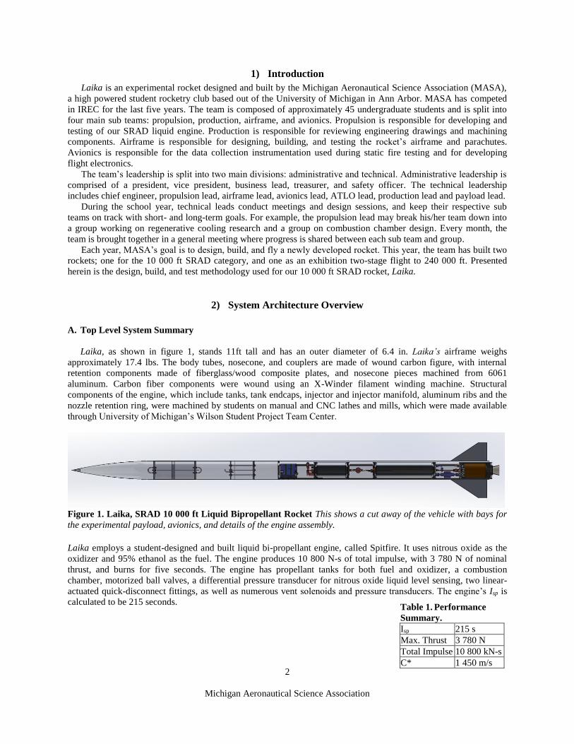
Laika, as shown in figure 1, stands 11ft tall and has an outer diameter of 6.4 in. Laika’s airframe weighs
approximately 17.4 lbs. The body tubes, nosecone, and couplers are made of wound carbon figure, with internal
retention components made of fiberglass/wood composite plates, and nosecone pieces machined from 6061
aluminum. Carbon fiber components were wound using an X-Winder filament winding machine. Structural
components of the engine, which include tanks, tank endcaps, injector and injector manifold, aluminum ribs and the
nozzle retention ring, were machined by students on manual and CNC lathes and mills, which were made available
through University of Michigan’s Wilson Student Project Team Center.
Laika employs a student-designed and built liquid bi-propellant engine, called Spitfire. It uses nitrous oxide as the
oxidizer and 95% ethanol as the fuel. The engine produces 10 800 N-s of total impulse, with 3 780 N of nominal
thrust, and burns for five seconds. The engine has propellant tanks for both fuel and oxidizer, a combustion
chamber, motorized ball valves, a differential pressure transducer for nitrous oxide liquid level sensing, two linear-
actuated quick-disconnect fittings, as well as numerous vent solenoids and pressure transducers. The engine’s Isp is
calculated to be 215 seconds.
Table 1. Performance
Summary.
Isp 215 s
Max. Thrust 3 780 N
Total Impulse 10 800 kN-s
C* 1 450 m/s
Figure 1. Laika, SRAD 10 000 ft Liquid Bipropellant Rocket This shows a cut away of the vehicle with bays for
the experimental payload, avionics, and details of the engine assembly.

3
Michigan Aeronautical Science Association
Figure 3: 3D Cross Section of
Nozzle Assembly
Figure 2: Thrust Data from 3 s Static Fire
B. Propulsion
1. Performance
The vehicle is propelled by a nitrous oxide and ethanol liquid bi-propellant engine which produces a maximum
thrust of 850 lbf. Engine performance was characterized by a series of three static hot fire tests. An extensive
characterization is provided in Appendix A and a summary of performance metrics is given in Table 1. Figure 2
shows thrust data collected during a five-second burn at a student built test site at the University of Michigan.
2. Propellant Systems
The fuel tank, oxidizer tank, and propellant plumbing
sections sit above the combustion chamber in a rigid assembly
bolted together with aluminum ribs. Between the chamber,
oxidizer tank, and fuel tank, there are two 8-inch tall plumbing
bays which house the propellant feed lines, motorized main
propellant valves, pressure transducers, and vent valves. The
fuel tank sits above the oxidizer tank, with a continuous,
unbroken fuel tube running into and through the oxidizer tank.
The tank tubes are made of Al 6061-T6, and the four tank end
caps are made of Al 7075. These components are student
machined and are designed to operate at 800 psi, with a 2.0
design SF, and have been hydrostatic tested to a 1.5 SF.
Nitrous oxide was selected as an oxidizer due to its
relative safety and high vapor pressure at typical ambient
temperatures, permitting self-pressurization. The engine was
designed to use 5.8 L of nitrous oxide in a 6.4 L tank, for a
mass of 4.4 kg. The oxidizer temperature was chosen as a
balance between oxidizer density at colder temperatures and
higher vapor pressure at higher temperatures. At the goal
temperature of 70˚ F, the nitrous oxide generates 750 psi of
vapor pressure.
Ethyl alcohol (ethanol) was chosen as the fuel due to high Isp, accessibility, and its documented performance in
other liquid propulsion systems. The fuel tank contains 1.43 L of 95% denatured ethanol and 2.16 L of nitrogen gas
at a nominal pressure of 750 psi. The N2 serves to force the fuel through the main fuel line to the injector.
3. Combustion Chamber
The combustion chamber is made from Al 6061-T6 and has a phenolic
impregnated cardboard liner to serve as an ablative. The nominal operating
pressure of the combustion chamber is 400 psi and the aluminum wall was
designed for a SF of 4 under room temperature conditions. This high SF
was used due to the temperature dependence of yield strength and has been
experimentally proven to be reliable. An L* of 85 was chosen to avoid
combustion related efficiency losses.
The nozzle consists of a superfine graphite converging section and
throat with a 304-stainless steel diverging section. Graphite was selected
due to its superior thermal properties and relative ease of manufacturing
when compared to similar materials. The steel diverging section is used to
hold the graphite in place and was designed using experimental thermal
results from the previous year’s hybrid engine nozzle. A 3D cross section of
the nozzle assembly is provided in Figure 3.
4. Injector
The injector is composed of two element styles with 16 unlike-impinging elements and 8 like-impinging oxidizer
elements. This combination of element styles was used to achieve the desired OF ratio of 4. The hole geometry for
the oxidizer elements is based off experimental data from the previous year’s hybrid engine and the methods
discussed in Ref. 1 to avoid feed-coupled instability and provide adequate mass distribution and mixing. Redundant
4
Michigan Aeronautical Science Association
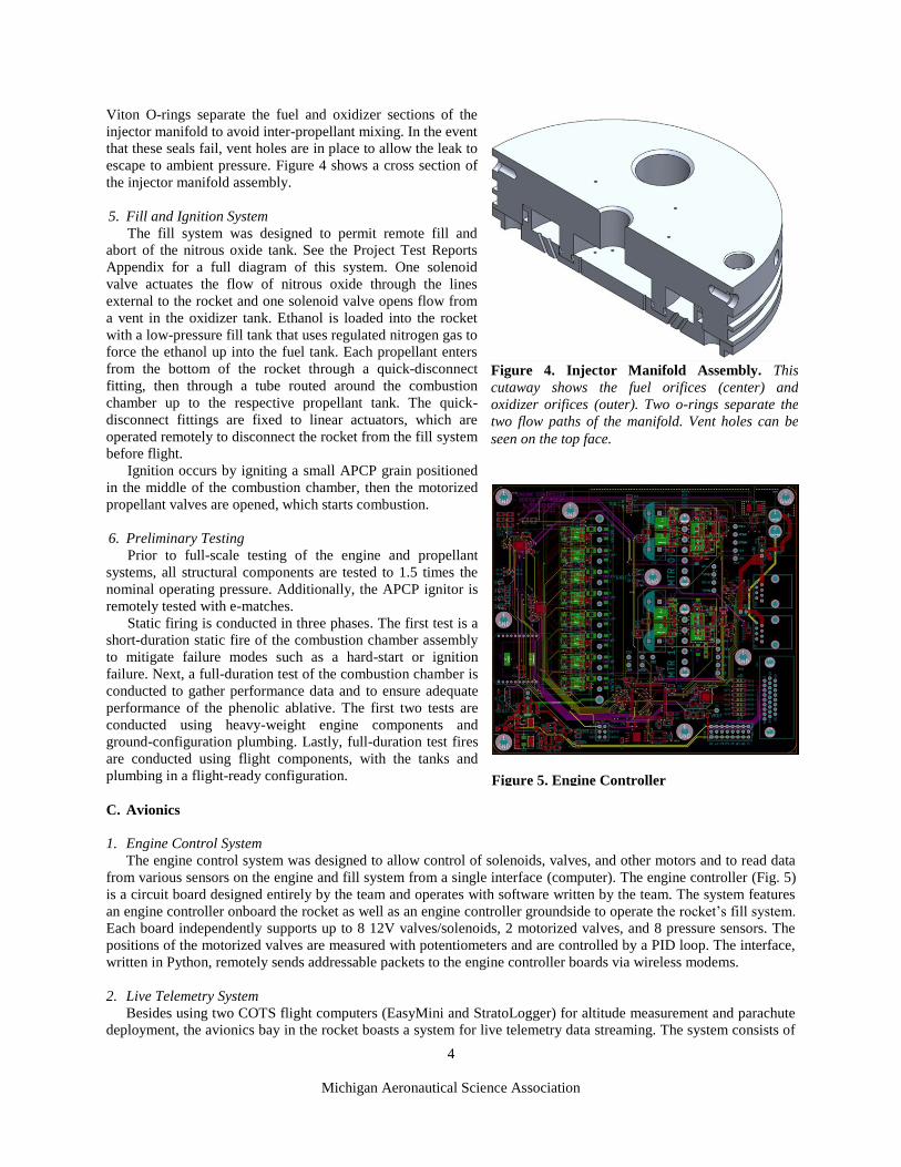
Viton O-rings separate the fuel and oxidizer sections of the
injector manifold to avoid inter-propellant mixing. In the event
that these seals fail, vent holes are in place to allow the leak to
escape to ambient pressure. Figure 4 shows a cross section of
the injector manifold assembly.
5. Fill and Ignition System
The fill system was designed to permit remote fill and
abort of the nitrous oxide tank. See the Project Test Reports
Appendix for a full diagram of this system. One solenoid
valve actuates the flow of nitrous oxide through the lines
external to the rocket and one solenoid valve opens flow from
a vent in the oxidizer tank. Ethanol is loaded into the rocket
with a low-pressure fill tank that uses regulated nitrogen gas to
force the ethanol up into the fuel tank. Each propellant enters
from the bottom of the rocket through a quick-disconnect
fitting, then through a tube routed around the combustion
chamber up to the respective propellant tank. The quick-
disconnect fittings are fixed to linear actuators, which are
operated remotely to disconnect the rocket from the fill system
before flight.
Ignition occurs by igniting a small APCP grain positioned
in the middle of the combustion chamber, then the motorized
propellant valves are opened, which starts combustion.
6. Preliminary Testing
Prior to full-scale testing of the engine and propellant
systems, all structural components are tested to 1.5 times the
nominal operating pressure. Additionally, the APCP ignitor is
remotely tested with e-matches.
Static firing is conducted in three phases. The first test is a
short-duration static fire of the combustion chamber assembly
to mitigate failure modes such as a hard-start or ignition
failure. Next, a full-duration test of the combustion chamber is
conducted to gather performance data and to ensure adequate
performance of the phenolic ablative. The first two tests are
conducted using heavy-weight engine components and
ground-configuration plumbing. Lastly, full-duration test fires
are conducted using flight components, with the tanks and
plumbing in a flight-ready configuration.
C. Avionics
1. Engine Control System
The engine control system was designed to allow control of solenoids, valves, and other motors and to read data
from various sensors on the engine and fill system from a single interface (computer). The engine controller (Fig. 5)
is a circuit board designed entirely by the team and operates with software written by the team. The system features
an engine controller onboard the rocket as well as an engine controller groundside to operate the rocket’s fill system.
Each board independently supports up to 8 12V valves/solenoids, 2 motorized valves, and 8 pressure sensors. The
positions of the motorized valves are measured with potentiometers and are controlled by a PID loop. The interface,
written in Python, remotely sends addressable packets to the engine controller boards via wireless modems.
2. Live Telemetry System
Besides using two COTS flight computers (EasyMini and StratoLogger) for altitude measurement and parachute
deployment, the avionics bay in the rocket boasts a system for live telemetry data streaming. The system consists of
Figure 4. Injector Manifold Assembly. This
cutaway shows the fuel orifices (center) and
oxidizer orifices (outer). Two o-rings separate the
two flow paths of the manifold. Vent holes can be
seen on the top face.
Figure 5. Engine Controller

5
Michigan Aeronautical Science Association
two circuit boards designed by the team. The board within the rocket has the following sensors: a barometer, an
accelerometer, 6 gyroscopes, and GPS. The board transmits telemetry data from these sensors to a receiving board
on the ground, which in turn displays the data to a connected computer. The onboard flight computer simultaneously
saves the flight data at a higher frequency to onboard flash. For redundancy, the avionics bay also holds a COTS
BigRedBee BeeLine GPS, which transmits the rocket’s coordinates.
D. Airframe
1. Performance
Performance simulations were run using Open Rocket, a free software by Sampo Niskanen. The simulations were
run using Spaceport America launch conditions, including an ambient temperature of 80°F, an altitude of 4596 ft
MSL, and wind speeds of 8 mph.1 Simulation results are shown in figures 4 and 5. Key performance characteristics
are as follows:
Altitude at Apogee: 8959 ft
Off-the rail velocity: 96.3 ft/s (Assuming 17 ft launch rail)
Maximum Mach number: 0.66
Thrust-to-weight ratio: 9.8
Max Q: 29.3 kPa (3.77s after ignition at 1650 ft AGL)
2. Nosecone Design
Laika uses an ogive nosecone profile with a fineness ratio of 3.9. An ogive nosecone was chosen since it is easier
to manufacture precisely than other slightly more optimal designs. The fineness ratio was optimized by running
multiple Open Rocket simulations to find the ratio that maximized altitude. Internally, the nosecone integrates an
adjustable ballast system and the drogue parachute bay. The removable nosecone tip is held on by a 3/8 -16 threaded
rod, which threads into the the aluminum nosecone tip and nosecone bulkhead. Various amounts of cast iron plates
can be threaded into any location on the rod and retained using nuts, which allows adjustment of Laika’s CG
location to set an appropriate stability margin as well as fine tune the rockets apogee. The nosecone is retained on
the avionics coupler with 4 4-40 shear pins, which shear at apogee to deploy the drogue.
3. Body Design
Laika’s body tubes are built from five layers of filament wound 12K carbon fiber tow and Huntsman Araldite LY
1568 / Aradur 3492 epoxy, an aerospace-grade heat cure
epoxy. The body tubes have an inner diameter of 6.25 in,
and an outer diameter of 6.45 in, resulting from an
approximately 0.1 in thickness of five layers of carbon
fiber. External aerodynamics of the body tubes are
optimized by maintaining the smoothest surface finish
possible, achieved through sanding, painting, and
polishing. The body tubes are broken into four sections:
nosecone/drogue parachute bay, main parachute recovery
section, upper motor section, and lower motor section.
The main recovery section contains the rocket’s main
parachutes, and is connected using the payload coupler
to the motor section. The motor section holds the motor
and the fins. Laika’s couplers are built using 5 layers of
filament wound carbon fiber, with an outer diameter of
6.25 in. This allows them to slide snugly inside the body
tubes. The payload coupler is approximately 12 in long
(two body diameters) to minimize bending, and are held
to the body tubes using 4 8-32 screws. The avionics
coupler is mounted with the same hardware, and is 16 in long with a 4 in vent band through which the flight
computers measure barometric pressure to track altitude.
Figure 6. Fiberglass Fin Dimensions

6
Michigan Aeronautical Science Association
4. Fin Design
The fins on Laika were designed to provide sufficient statics stability while minimizing drag. In order to archive
the desired static stability the fins had to be large enough to pull the rockets center of pressure (Cp) to at least one
and a half body tube diameters behind the center of gravity. The fins were designed as clipped deltas to ease
construction and reduce the risk of a fin hitting first on recovery and breaking. Figure 6 shows the dimensions of the
fins. The fins were made from ⅛ inch G10 fiberglass sheet and attached to the body with structural fillets made from
filled epoxy. Two layers of fiberglass cloth were laminated over the fins in a process known as tip-to-tip to further
reinforce them.
Flutter analysis was performed on the fins using the Barrowman 3D method. The divergence velocity was found
to be 1.58 Mach and the flutter velocity was found to be 2.15 Mach, both values are significantly above the rocket
velocity.
5. Structural Integration
Structural integration of Laika was designed in several sections - drogue recovery section/nosecone, avionics bay,
main recovery section, payload bay, and motor integration.
The drogue recovery section is contained within the
nosecone and houses Laika’s drogue parachute and
associated shock cords and chute nomex parachute
protectors. There is a bulkhead at the top of the nosecone
that secures the nosecone tip. The shock cord attaches to a
U-bolt mounted to this bulkhead. The other end attaches to a
forward bulkhead attached to the avionics coupler. The
nosecone is attached to the avionics coupler with 4 4-40
nylon shear pins, allowing the nosecone to separate and the
parachute to deploy at apogee.
The avionics bay is a coupler with bulkheads on both
ends, allowing it to conveniently connect the main recovery
section and the nosecone. Both bulkheads are connected by
a pair of 3/8 -16 aluminum threaded rods, which support the
shock load of parachute deployment and hold the rocket
body to the parachutes. A plywood board is mounted on
these threaded rods with metal brackets, and secured with
nuts on both ends. The avionics components are mounted to
this board using appropriate screws.
The main recovery section is an empty tube containing
Laika’s main parachute and associated shock cords and
chute nomex parachute protectors. There are bulkheads on
both ends of the recovery bay, attached to the bottom of the
avionics coupler and the top of the payload coupler, to take
recovery loads. The top of the recovery tube is attached to
the avionics coupler with 4 4-40 nylon shear pins allowing
the rocket to separate and the parachute deploy at apogee.
The payload, an 8.8 lb rectangular prism, is contained in
the payload bay which also acts as a coupler joining the
main recovery section to the motor section using 8-32
screws.
Motor retention is based on secure hard-points along ribs
running along the motor and thrust plates at the base. There
are three T - shaped thrust plates at the base of the rocket
which transfer the thrust to the airframe. The motor is
attached to 6061 Aluminum ribs that run along the sides,
and secured to these ribs are threaded bumpers that align with holes in the airframe. The bumpers ensure the motor
is centered throughout the airframe, and provide negative retention for the motor stack. The motor is secured to the
airframe with 3 8-32 screws in 4 locations along the length of the motor section.
Figure 7. Simulated Altitude Over Time The above
result was obtained using OpenRocket
Figure 8. Simulated Velocity Over Time The above
result was obtained using OpenRocket
7
Michigan Aeronautical Science Association
6. Rail Guides
1515 rail guides were placed midway between fins to avoid interference with the rail. One rail pin is placed 2 in
from the base of the rocket and the other was placed 7 ft above that forward of the center of mass. Both rail guides
are fastened to the body using manufacturer-supplied screws and nuts.
E. Recovery
1. Drogue Parachute Design
The drogue parachute is released at apogee to limit rocket descent velocity to comply with IREC regulations,
maintain a reasonable descent velocity while minimizing drift, and orient the main rocket body for main parachute
deployment. It is constructed using 1.2 oz ripstop nylon, a material chosen due to its relatively low cost, high tensile
strength, high melting point, and optimal permeability. The drogue parachute is circular, and has a diameter of 4 ft
with a spill hole diameter of 4 in. Using OpenRocket simulations and the dry mass of Laika, a descent velocity of
approximately 85 ft/s was calculated. The body tube and nosecone are suspended from the drogue parachute through
a network of shroud lines and shock cords. There are 8 Kevlar shroud lines, connected by a quick link to a 50 ft
length of 1 in tubular nylon shock cord that attaches to 3/8 in U-bolts attached to the nosecone bulkhead and forward
avionics bulkhead. Line connections are made using quick links to streamline assembly and replacement of damaged
lines.
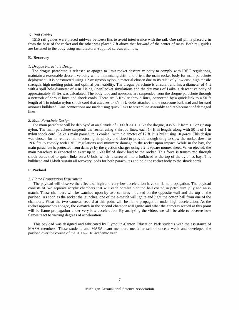
2. Main Parachute Design
The main parachute will be deployed at an altitude of 1000 ft AGL. Like the drogue, it is built from 1.2 oz ripstop
nylon. The main parachute suspends the rocket using 8 shroud lines, each 14 ft in length, along with 50 ft of 1 in
nylon shock cord. Laika’s main parachute is conical, with a diameter of 17 ft. It is built using 10 gores. This design
was chosen for its relative manufacturing simplicity and sized to provide enough drag to slow the rocket down to
19.6 ft/s to comply with IREC regulations and minimize damage to the rocket upon impact. While in the bay, the
main parachute is protected from damage by the ejection charges using a 2 ft square nomex sheet. When ejected, the
main parachute is expected to exert up to 1600 lbf of shock load to the rocket. This force is transmitted through
shock cords tied to quick links on a U-bolt, which is screwed into a bulkhead at the top of the avionics bay. This
bulkhead and U-bolt sustain all recovery loads for both parachutes and hold the rocket body to the shock cords.
F. Payload
1. Flame Propagation Experiment
The payload will observe the effects of high and very low acceleration have on flame propagation. The payload
consists of two separate acrylic chambers that will each contain a cotton ball coated in petroleum jelly and an e-
match. These chambers will be watched upon by two cameras mounted on the opposite wall and the top of the
payload. As soon as the rocket the launches, one of the e-match will ignite and light the cotton ball from one of the
chambers. What the two cameras record at this point will be flame propagation under high acceleration. As the
rocket approaches apogee, the e-match in the second chamber will ignite and what the cameras record at this point
will be flame propagation under very low acceleration. By analyzing the video, we will be able to observe how
flames react to varying degrees of acceleration.
This payload was designed and fabricated by Plymouth-Canton Education Park students with the assistance of
MASA members. These students and MASA team members met after school once a week and developed the
payload over the course of the 2017-2018 academic year.

8
Michigan Aeronautical Science Association
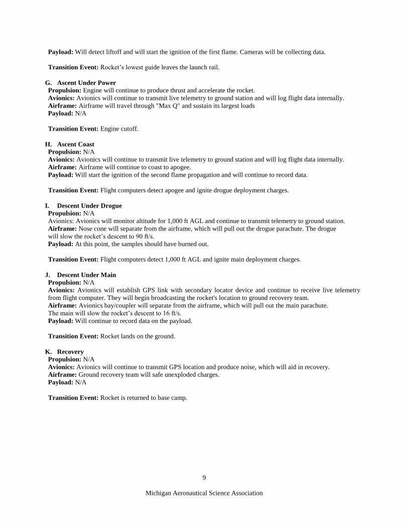
3) Mission Concept of Operations Overview
This section outlines the mission phases of a nominal flight. Subsystem performance during each of
these phases are also provided. A designation of N/A implies that the subsystem is either inactive during this
period.
A. Assembly Propulsion: N/A
Avionics: N/A
Airframe: N/A
Payload: N/A
Transition Event: Rocket construction and inspection are complete and Laika is ready to be carried to the pad.
B. Pad Setup Propulsion: Support systems will be assembled and connected to the fill system. Rocket will be loaded onto the rail.
Avionics: Pad systems will be set up. Wireless link to flight computer and engine controller will be established.
Avionics will be safed at this stage.
Airframe: Laika’s weight will be fully supported by the lowest rail guide.
Payload: Cameras will be turned on at the point recording data
Transition Event: Rocket is set up on the pad and all non-essential personnel are outside the safety perimeter.
C. Fuel Fill Propulsion: Unpressurized ethanol will be loaded into the rocket by ground crew.
Avionics: N/A
Airframe: N/A
Payload: Will continue to collect data from a camera. No ignition inside of the payload has occurred yet.
Transition Event: Rocket is filled with fuel and all personnel are outside the safety perimeter.
D. Oxidizer Fill Propulsion: Rocket will be loaded with nitrous oxide and fuel tank will be pressurized to flight pressure with
nitrogen. Fill lines will be decoupled and separation will be tested. This process is controlled by ground crew outside
the safety perimeter.
Avionics: Ground avionics will facilitate nitrous oxide loading.
Airframe: Airframe will bare increased weight.
Payload: N/A
Transition Event: Rocket is fully fueled and ready for flight.
E. Ignition Propulsion: Ignition command will be sent to the custom ignition device and main valves will be commanded to
open, which will trigger the engine's startup. Chamber pressure and thrust climb to nominal values.
Avionics: Avionics will control igniter and valves.
Airframe: Will begin to bear thrust loads.
Payload: N/A
Transition Event: Engine thrust overcomes a thrust to weight ratio of 1 and the airframe begins to
lift off the rail.
F. Liftoff Propulsion: Engine will continue to build thrust.
Avionics: COTS flight computers will detect liftoff and begin logging data.
Airframe: Airframe will begin lifting off it’s support block and will be guided by the launch rail. At the
point the lowest guide leaves the rail, the Laika will be traveling at 107 ft/s.
9
Michigan Aeronautical Science Association
Payload: Will detect liftoff and will start the ignition of the first flame. Cameras will be collecting data.
Transition Event: Rocket’s lowest guide leaves the launch rail.
G. Ascent Under Power Propulsion: Engine will continue to produce thrust and accelerate the rocket.
Avionics: Avionics will continue to transmit live telemetry to ground station and will log flight data internally.
Airframe: Airframe will travel through "Max Q" and sustain its largest loads
Payload: N/A
Transition Event: Engine cutoff.
H. Ascent Coast Propulsion: N/A
Avionics: Avionics will continue to transmit live telemetry to ground station and will log flight data internally.
Airframe: Airframe will continue to coast to apogee.
Payload: Will start the ignition of the second flame propagation and will continue to record data.
Transition Event: Flight computers detect apogee and ignite drogue deployment charges.
I. Descent Under Drogue Propulsion: N/A
Avionics: Avionics will monitor altitude for 1,000 ft AGL and continue to transmit telemetry to ground station.
Airframe: Nose cone will separate from the airframe, which will pull out the drogue parachute. The drogue
will slow the rocket’s descent to 90 ft/s.
Payload: At this point, the samples should have burned out.
Transition Event: Flight computers detect 1,000 ft AGL and ignite main deployment charges.
J. Descent Under Main Propulsion: N/A
Avionics: Avionics will establish GPS link with secondary locator device and continue to receive live telemetry
from flight computer. They will begin broadcasting the rocket's location to ground recovery team.
Airframe: Avionics bay/coupler will separate from the airframe, which will pull out the main parachute.
The main will slow the rocket’s descent to 16 ft/s.
Payload: Will continue to record data on the payload.
Transition Event: Rocket lands on the ground.
K. Recovery Propulsion: N/A
Avionics: Avionics will continue to transmit GPS location and produce noise, which will aid in recovery.
Airframe: Ground recovery team will safe unexploded charges.
Payload: N/A
Transition Event: Rocket is returned to base camp.
10
Michigan Aeronautical Science Association
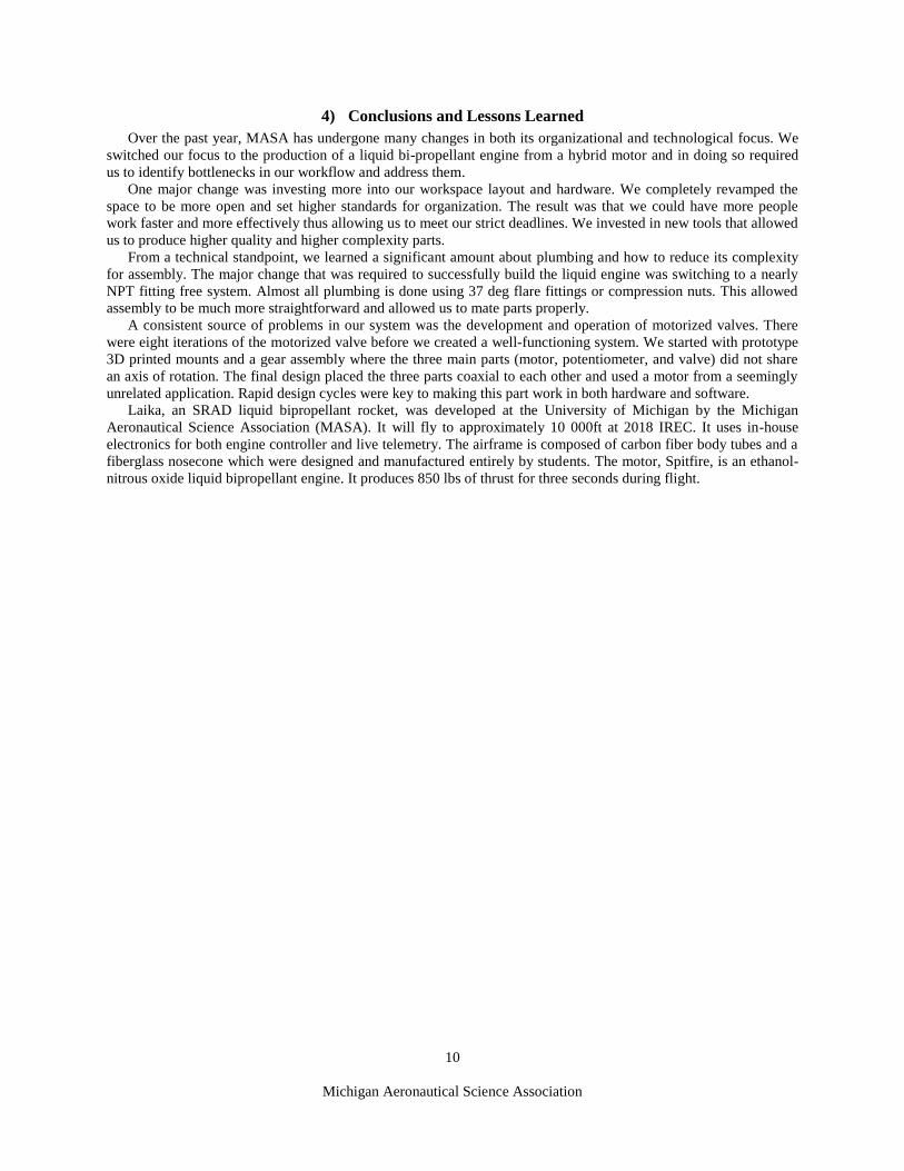
4) Conclusions and Lessons Learned
Over the past year, MASA has undergone many changes in both its organizational and technological focus. We
switched our focus to the production of a liquid bi-propellant engine from a hybrid motor and in doing so required
us to identify bottlenecks in our workflow and address them.
One major change was investing more into our workspace layout and hardware. We completely revamped the
space to be more open and set higher standards for organization. The result was that we could have more people
work faster and more effectively thus allowing us to meet our strict deadlines. We invested in new tools that allowed
us to produce higher quality and higher complexity parts.
From a technical standpoint, we learned a significant amount about plumbing and how to reduce its complexity
for assembly. The major change that was required to successfully build the liquid engine was switching to a nearly
NPT fitting free system. Almost all plumbing is done using 37 deg flare fittings or compression nuts. This allowed
assembly to be much more straightforward and allowed us to mate parts properly.
A consistent source of problems in our system was the development and operation of motorized valves. There
were eight iterations of the motorized valve before we created a well-functioning system. We started with prototype
3D printed mounts and a gear assembly where the three main parts (motor, potentiometer, and valve) did not share
an axis of rotation. The final design placed the three parts coaxial to each other and used a motor from a seemingly
unrelated application. Rapid design cycles were key to making this part work in both hardware and software.
Laika, an SRAD liquid bipropellant rocket, was developed at the University of Michigan by the Michigan
Aeronautical Science Association (MASA). It will fly to approximately 10 000ft at 2018 IREC. It uses in-house
electronics for both engine controller and live telemetry. The airframe is composed of carbon fiber body tubes and a
fiberglass nosecone which were designed and manufactured entirely by students. The motor, Spitfire, is an ethanol-
nitrous oxide liquid bipropellant engine. It produces 850 lbs of thrust for three seconds during flight.

11
Michigan Aeronautical Science Association
Appendix A: System Weights, Measures and Performance Data
See attached progress report.
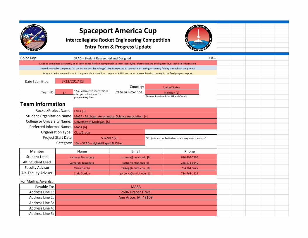
Spaceport America CupIntercollegiate Rocket Engineering Competition
Entry Form & Progress Update
Color Key SRAD = Student Researched and Designed v18.1
Must be completed accurately at all time. These fields mostly pertain to team identifying information and the highest-level technical information.
Should always be completed "to the team's best knowledge" , but is expected to vary with increasing accuracy / fidelity throughout the project.
May not be known until later in the project but should be completed ASAP, and must be completed accurately in the final progress report.
Date Submitted: 3/23/2017 [1]Country: United States
Team ID: 37 * You will receive your Team ID after you submit your 1st project entry form.
State or Province: Michigan [2]State or Province is for US and Canada
Team InformationRocket/Project Name: Laika [3]
Student Organization Name MASA - Michigan Aeronautical Science Association [4]College or University Name: University of Michigan [5]
Preferred Informal Name: MASA [6]Organization Type: Club/GroupProject Start Date 7/1/2017 [7] *Projects are not limited on how many years they take*
Category: 10k – SRAD – Hybrid/Liquid & Other
Member Name Email PhoneStudent Lead Nicholas Sterenberg [email protected] [8] 616-402-7196
Alt. Student Lead Cameron Buccellato [email protected] [9] 248-978-9640
Faculty Advisor Mirko Gamba [email protected] [10] 734 764 6675
Alt. Faculty Adviser Chris Gordon [email protected] [11] 734-763-1224
For Mailing Awards:Payable To: MASA
Address Line 1: 2606 Draper DriveAddress Line 2: Ann Arbor, MI 48109Address Line 3:Address Line 4:Address Line 5:
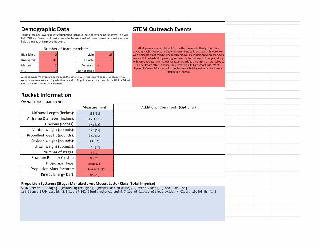
Demographic Data STEM Outreach EventsThis is all members working with your project including those not attending the event. This will help ESRA and Spaceport America promote the event and get more sponsorships and grants to help the teams and improve the event.
MASA provides various benefits to the the community through outreach programs such as Aerospace Day where members build and launch Estes rockets with elementary and middle school students, Design Immersion where members work with hundreds of Engineering freshmen in the first week of the year, along with participating at afterschool events and Math/Science nights at local schools.
Our outreach efforts also include partnering with high school students at Plymouth Canton Educational Park to design and build a payload to be flown at
competition this year.
Number of team membersHigh School 0 Male 29
Undergrad 31 Female 4
Masters 2 Veterans no
PhD 0 NAR or Tripoli 1
Just a reminder the you are not required to have a NAR, Tripoli member on your team. If your country has an equivelant organization to NAR or Tripoli, you can cant them in the NAR or Tripoli box. CAR from Canada is an example.
Rocket InformationOverall rocket parameters:
Measurement Additional Comments (Optional)Airframe Length (inches): 132 [12]
Airframe Diameter (inches): 6.45 OD [13]
Fin-span (inches): 19.5 [14]
Vehicle weight (pounds): 66.5 [15]
Propellent weight (pounds): 12.2 [16]
Payload weight (pounds): 8.8 [17]
Liftoff weight (pounds): 87.5 [18]
Number of stages: 1 [19]
Strap-on Booster Cluster: No [20]
Propulsion Type: Liquid [21]
Propulsion Manufacturer: Student-built [22]
Kinetic Energy Dart: No [23]
Propulsion Systems: (Stage: Manufacturer, Motor, Letter Class, Total Impulse)SRAD Format - [Stage]: [Motor/Engine Type], [Propellant mixture], [Letter Class], [Total Impulse]1st Stage: SRAD Liquid, 2.5 lbs of 95% liquid ethanol and 9.7 lbs of liquid nitrous oxide, N Class, 10,800 Ns [24]

SRAD Format - [Stage]: [Motor/Engine Type], [Propellant mixture], [Letter Class], [Total Impulse]1st Stage: SRAD Liquid, 2.5 lbs of 95% liquid ethanol and 9.7 lbs of liquid nitrous oxide, N Class, 10,800 Ns [24]
Total Impulse of all Motors: 10,800 [25] (Ns)
Predicted Flight Data and AnalysisThe following stats should be calculated using rocket trajectory software or by hand.Pro Tip: Reference the Barrowman Equations, know what they are, and know how to use them.
Measurement Additional Comments (Optional)
Launch Rail:ESRA Provide Rail
[26]Rail Length (feet): 17 [27]
Liftoff Thrust-Weight Ratio: 9.8 ~850 lbs of thrust, ~87 lbs launch massLaunch Rail Departure Velocity (feet/second): 96
Minimum Static Margin During Boost: 3.72 *Between rail departure and burnoutMaximum Acceleration (G): 8.83 Maximum thrust is ~0.1 seconds after liftoff
Maximum Velocity (feet/second): 768
Target Apogee (feet AGL): 10K [28]
Predicted Apogee (feet AGL): 8,952
Payload InformationPayload Description:
The Payload will attempt to observe the effects of combustion under both high and low acceleration by using high speed cameras to catch the events. We plan to compare our results with the same test run on the ground under
nominal conditions. We will be lighting two seperate cotton balls in their own compartments at takeoff where the combustion will experience high acceleration. We also will be lighting another two seperate cotton balls in their own
compartments at apogee where the combustion will experience microgravity.
Recovery Information
The rocket recovers in three sections attached by nylon cords. These sections are the nose cone, avonics bay, and main body tube. The drouge chute is made from ripsto nylon, has a diameter of 24in inches, and is deployed by
barometric detection of apogee. The main chute is made from ripsto nylon, has a diameter of 6.5 feet, and is deployed by barometric detection of 1000ft using the stratologger and easymini flight computers. All events have a
primary and back-up charge
Planned Tests * Please keep briefDate Type Description Status Comments
10/28/17 Ground Partial-duration liquid engine test Successful Tanks and plumbing not in flight config.11/12/17 Ground Full-duration liquid engine test Successful Tanks and plumbing not in flight config.
3/17/18 Ground Full-duration test w/ flight tanks Successful Tanks and plumbing IN flight config.5/12/18 Ground Final pre-flight engine test Successful Engine and tanks ready for flight

5/16/18 Ground Engine-to-airframe integration test TBD Physical fit between engine and airframe
5/29/18 Ground Engine fill and drain, full rocket assembly TBD
Fill/drain tanks with nitrous and water in a fully assembled rocket
Ground Seperation Tests TBD standard deployment test4/7/18 In-FlightTest of recovery and avionics using solid test platformTBDUsing solid to 10k. Testing live telemetry downlink from custom flight computer

Any other pertinent information:
The liquid engine, tanks, and all associated plumbing is in its final configuration for flight. This configuration was tested in a successful hotfire on 3/17/18. We plan to hotfire at least once more after modifications are made to the
nitrous and ethanol fill system.
The liquid engine, tanks, and all associated plumbing is in its final configuration for flight. This configuration was tested in a successful hotfire on 3/17/18. We plan to hotfire at least once more after modifications are made to the
nitrous and ethanol fill system.
End of File
12
Michigan Aeronautical Science Association
Appendix B: Project Tests Reports
A. SRAD Propulsion System Testing
Throughout the 2017-2018 school year, Spitfire was static fired a total of 3 times, in addition to 2 static fires
with a smaller development engine. These tests provided valuable data regarding the performance of the engine and
potential problems with procedures involving setup, propellant fill, and avionics. The first 3 static fires were
conducted in the fall of 2017 with a smaller proof-of-concept engine. These tests validated the combustion chamber,
injector, ignition, fill procedure, and motorized valve design. Preliminary problems such as unreliable motorized
valves and ignition were identified and subsequently fixed in the 2 static fires of this small engine.
Shortly after the successful development engine tests, the team progressed to developing flight hardware and
ground support equipment. This hardware was tested in 3 static fires, with the last static fire being an engine stack
test comprised of flight propellant tanks, motorized valves, fill system, quick disconnect actuators, and fill
procedures.
Below is a picture of our most recent static fire setup. It is a full engine stack test to collect data for final flight
simulations. Below the engine stack is the thrust stand, which is comprised of an assembly to bolt onto the
combustion chamber, a flame trench which redirects exhaust horizontally, and water cooling to prevent the flame
trench from burning through. There are numerous sensors attached to the engine during a normal test. There are 5
pressure transducers monitoring the pressure of the propellant tanks, fuel and oxidizer injector manifolds, and
combustion chamber. To collect thrust data, 4 load cells are placed under the combustion chamber. These sensors
connect to a DAQ, which sits directly outside the bunker, in addition to the engine controller which collects low
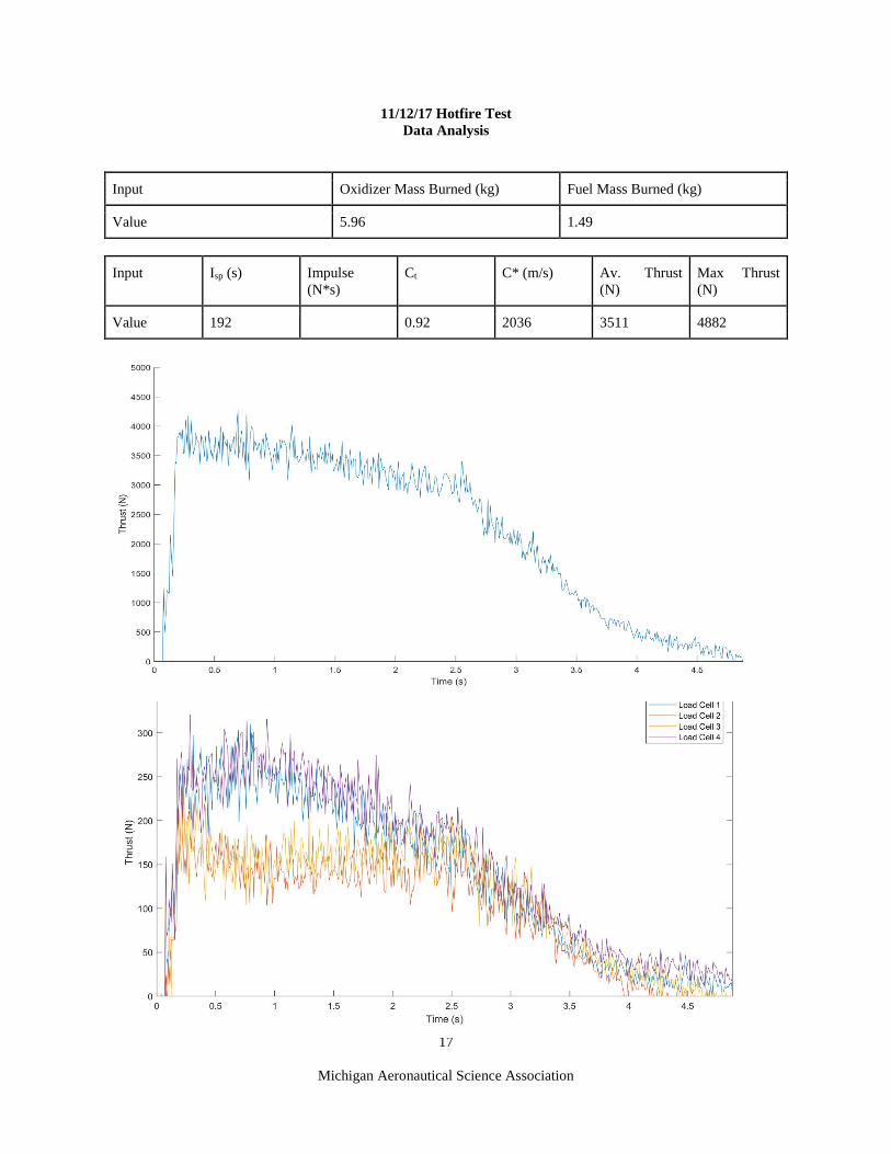
speed data. Attached next are the performance metrics of the 3 static fires of the liquid engine.
Figure 9. Static Fire Test Setup
13
Michigan Aeronautical Science Association
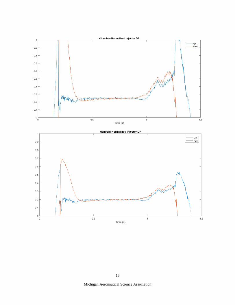
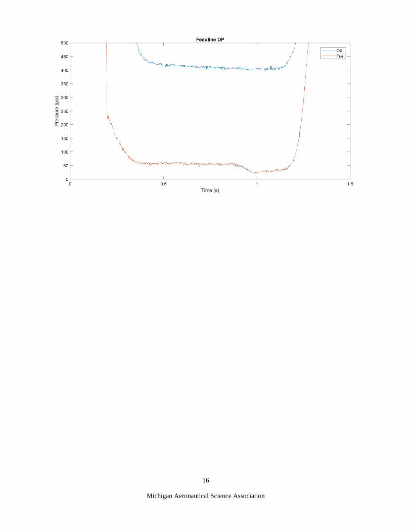
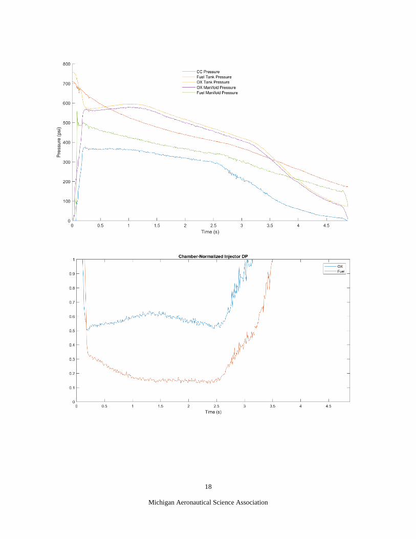
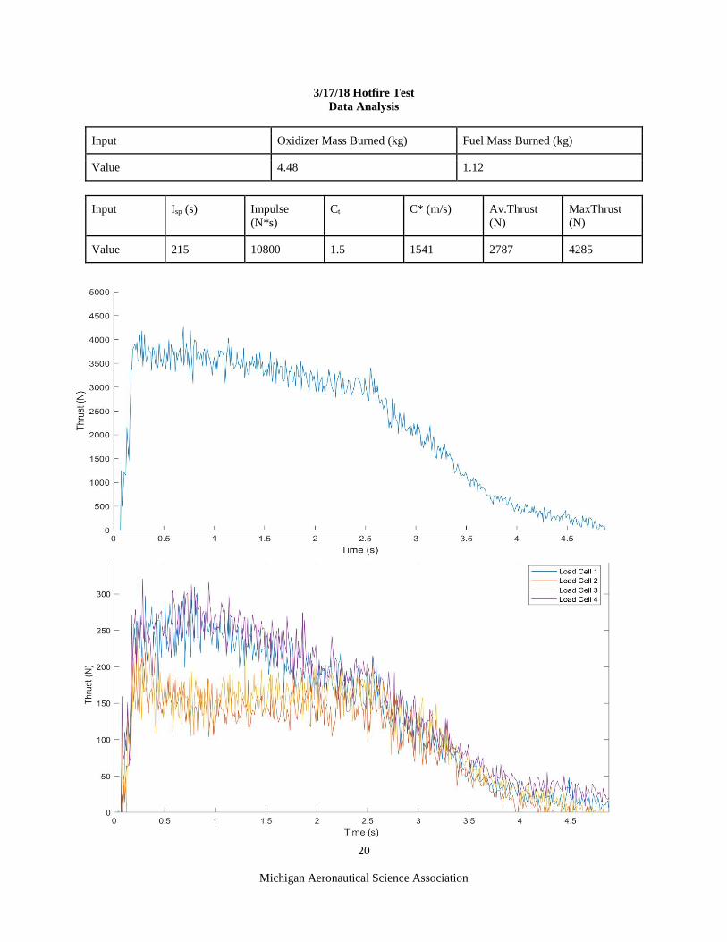
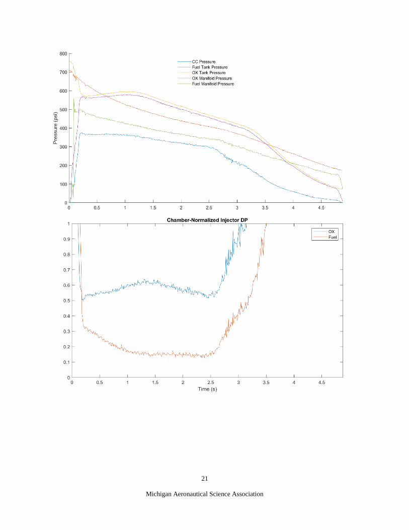
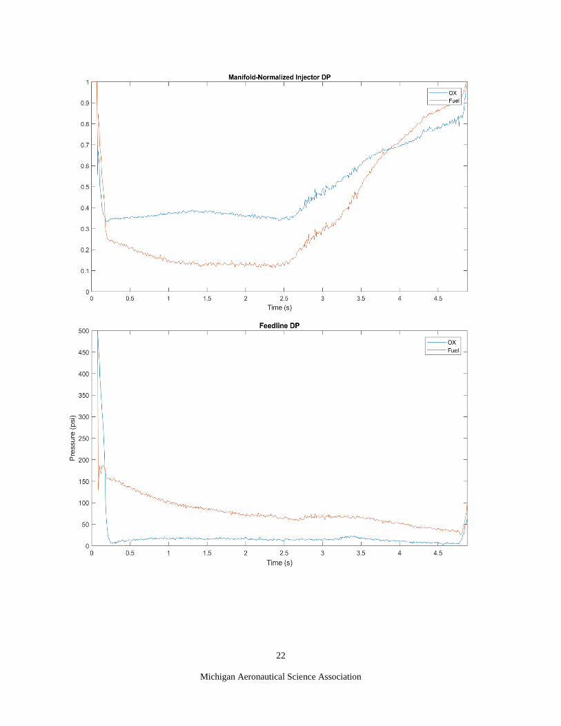
Below is the test data from the 3 most recent static fires of Spitfire, an SRAD liquid engine. The figures, in this
order, describe the overall thrust, individual thrust recorded from load cells, pressures in pressure vessels and
important components, pressure drop across the injector orifices normalized by the injector manifold pressure and
chamber pressure for both oxidizer and fuel, and pressure drop across the feedlines from tank to injector in both
oxidizer and fuel lines
10/28/17 Hotfire Test
Data Analysis
Input Oxidizer Mass Burned (kg) Fuel Mass Burned (kg)
Value 1.48 0.37
Input Isp (s) Impulse
(N*s)
Ct C* (m/s) Av. Thrust
(N)
Max Thrust
(N)
Value 218 0.98 2049 3986 4285
14
Michigan Aeronautical Science Association
15
Michigan Aeronautical Science Association
16
Michigan Aeronautical Science Association
17
Michigan Aeronautical Science Association
11/12/17 Hotfire Test
Data Analysis
Input Oxidizer Mass Burned (kg) Fuel Mass Burned (kg)
Value 5.96 1.49
Input Isp (s) Impulse
(N*s)
Ct C* (m/s) Av. Thrust
(N)
Max Thrust
(N)
Value 192 0.92 2036 3511 4882
18
Michigan Aeronautical Science Association

19
Michigan Aeronautical Science Association
20
Michigan Aeronautical Science Association
3/17/18 Hotfire Test
Data Analysis
Input Oxidizer Mass Burned (kg) Fuel Mass Burned (kg)
Value 4.48 1.12
Input Isp (s) Impulse
(N*s)
Ct C* (m/s) Av.Thrust
(N)
MaxThrust
(N)
Value 215 10800 1.5 1541 2787 4285
21
Michigan Aeronautical Science Association
22
Michigan Aeronautical Science Association

23
Michigan Aeronautical Science Association
B. SRAD Pressure Vessel Testing
All systems which will operate at an elevated pressure are hydro-statically pressure tested to at least 1.5x
MEOP. For the oxidizer tank, fuel tank, this value is 1200 psi. The chamber was pressure tested to 1200 psi.
Pressure testing is accomplished using a Rice Hydro hand pump, which has a maximum operating pressure of 2000
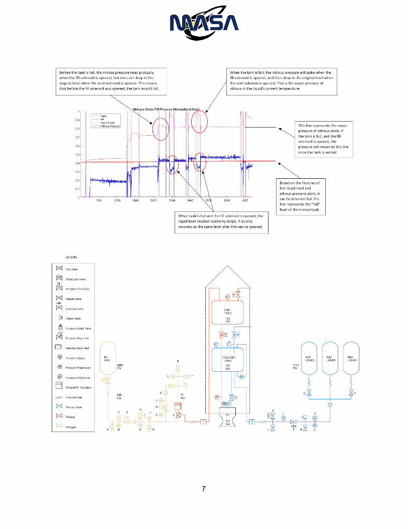
psi. Below is the P&ID diagram of Laika.
C. Recovery Testing
Laika’s recovery system was tested by ground separation tests. This method is used to determine
the size of the blackpowder charges required to consistently separate the nosecone and release the drogue
parachute. These tests yielded a charge size of 5 g of 4F black powder for the main parachute, excluding the
mass of the e-match and charge packaging. A secondary charge with 6.5 grams of black powder will also be
flown as backup incase the first charge fails to separate the rocket. The drogue bay will use a 3.5-gram black
powder charge with a 4.5-gram redundant charge.
1. Flight Avionics
Two flight computers will be used for redundancy, both of which are mounted in the avionics bay. The
primary flight computer is a Easy-Mini, and the secondary flight computer is a PerfectFlite Stratologger CF. Two
different flight computers were specifically chosen to avoid any failure mode that may be specific to a certain flight
Figure 10. Plumbing and Instrumentation Diagram

24
Michigan Aeronautical Science Association
computer. The primary flight computer is set to fire its separation charge at apogee, and its main parachute charge at
1 000 ft AGL. The secondary flight computer is set to fire its separation charge at delay of 2 seconds after apogee,
and its main parachute charge at 800 ft AGL. These delays ensure that sufficient time has passed so that charges in
too quick succession do not damage any recovery components, but are close enough together to minimize any
harmful effects to the recovery sequence.
Also, onboard the rocket is a custom board flight computer for high speed data logging. This PCB was
designed by MASA’s avionics team to help characterize the forces incurred during parachute deployment.
Commercial flight computers generally record acceleration at too low a rate to resolve the impulsive forces of
parachute deployment. This custom flight computer will record accelerometer data at close to 1 KHz. The flight
computer was also designed to be able to deploy the rocket’s parachutes, however, minimal testing has been done on
this system and it will not be used in the 2018 Spaceport America Cup flight. All the commercial flight computer
circuits and procedures are designed to minimize the chances of a premature charge detonation. Until installation in
the rocket, ejection charges will have their leads shorted. After installation, the flight computer power lines are
passed through a magnetic switch. Until the rocket is on the pad, the switches remain off, preventing any potential
power spikes that could set off the charges. When on the pad and ready for launch, the flight computers are armed
by passing a magnet near the magnetic switches, turning on the power to the flight computers.
Figure 11. Redundant Recovery Avionics Wiring Diagram

25
Michigan Aeronautical Science Association
D. Live Telemetry Testing
The live telemetry system built by the team utilizes two printed circuit boards. The first board, which flies
on the rocket, has a barometer, accelerometer, 6 gyroscopes, and GPS. During flight, this board simultaneously
records data to onboard flash and transmits to another board on the ground. The ground-side board transmits data to
a laptop to be displayed.
To test this system, it was flown on a rocket powered by a M motor to an altitude of 10,000+ feet. The two
boards remained in radio contact throughout the entire flight and descent. The team was able to see the rocket’s
maximum altitude live, use the system’s transmitted position to recover the rocket, and recover the saved data from
the circuit board within the rocket. This flight was essential to validate that the system would perform optimally
under the circumstances of high velocity and high altitude. The only major change to the system post-test was to add
a switch between rocket-side circuit board and its battery, so that the battery wouldn’t be depleted during rocket
integration.

26
Michigan Aeronautical Science Association
Appendix C: Hazard Analysis
See attached hazard analysis.
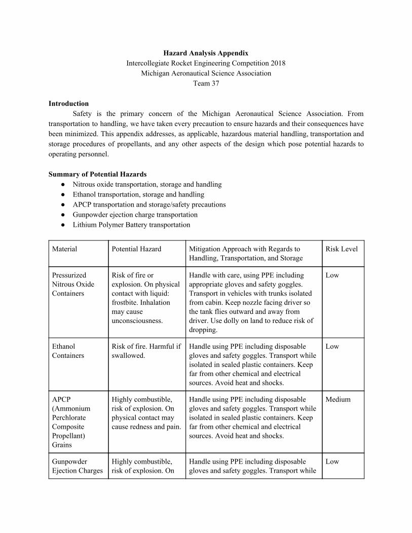
Hazard Analysis Appendix Intercollegiate Rocket Engineering Competition 2018
Michigan Aeronautical Science Association Team 37
Introduction
Safety is the primary concern of the Michigan Aeronautical Science Association. From transportation to handling, we have taken every precaution to ensure hazards and their consequences have been minimized. This appendix addresses, as applicable, hazardous material handling, transportation and storage procedures of propellants, and any other aspects of the design which pose potential hazards to operating personnel.
Summary of Potential Hazards
● Nitrous oxide transportation, storage and handling ● Ethanol transportation, storage and handling ● APCP transportation and storage/safety precautions ● Gunpowder ejection charge transportation ● Lithium Polymer Battery transportation
Material Potential Hazard Mitigation Approach with Regards to Handling, Transportation, and Storage
Risk Level
Pressurized Nitrous Oxide Containers
Risk of fire or explosion. On physical contact with liquid: frostbite. Inhalation may cause unconsciousness.
Handle with care, using PPE including appropriate gloves and safety goggles. Transport in vehicles with trunks isolated from cabin. Keep nozzle facing driver so the tank flies outward and away from driver. Use dolly on land to reduce risk of dropping.
Low
Ethanol Containers
Risk of fire. Harmful if swallowed.
Handle using PPE including disposable gloves and safety goggles. Transport while isolated in sealed plastic containers. Keep far from other chemical and electrical sources. Avoid heat and shocks.
Low
APCP (Ammonium Perchlorate Composite Propellant) Grains
Highly combustible, risk of explosion. On physical contact may cause redness and pain.
Handle using PPE including disposable gloves and safety goggles. Transport while isolated in sealed plastic containers. Keep far from other chemical and electrical sources. Avoid heat and shocks.
Medium
Gunpowder Ejection Charges
Highly combustible, risk of explosion. On
Handle using PPE including disposable gloves and safety goggles. Transport while
Low

physical contact may cause redness and pain.
isolated in sealed plastic containers. Keep far from other chemical and electrical sources. Avoid heat and shocks.
Lithium Polymer Battery
On physical contact may cause redness and pain.
Store in dark, cool location in Lithium Polymer safe transport bag. Avoid heat.
Low

27
Michigan Aeronautical Science Association
Appendix D: Risk Assessment
See attached risk assessment matrix.

IREC 2018 - Liquid 10k Category, Risk Analysis/Mitigation Michigan Aeronautical Science Association
Phase of Flight System Hazard Possible Cause Preventative Measures Mitigation Approach Risk of Mishap and Rationale
Likelihood of Injury After Mitigation
Assembly Avionics
Recovery system deploys on the ground
Flight computer malfunction; Ejection charge wire malfunction
Do not arm flight computers until on the pad; Shunt all ejection charges and frequently check for continuity
Handle ejection charges with proper PPE; Evacuate the vicinity and contact the proper launch site personnel
Low, recovery system avionics are tested extensively before integrated with ejection charges
Medium
Pad Setup
Propulsion
Propellant Leak Improper sealing of plumbing
Snoop tests, air pressure testing
If large leak, drain and retighten all joints.
High, small leaks tend to occasionally happen
Low
Main Valve Opening Failure
Engine controller malfunction, unresponsive motor
Redundant mechanical system, multiple tests
Use redundant mechanical system
Low, has been repeatedly tested
Solenoid Opening Failure
Unresponsive solenoid
Redundant mechanical system, multiple tests
Use redundant mechanical system
Low, commercial solenoid Low
Quick disconnect failed to detatch
Mechanical failure, unresponsive linear actuator
Redundant mechanical system, multiple tests
Use redundant mechanical system
Low, extensive testing of system
Low
On pad pressure failure
Extremely high pressure in tanks
Hydrostatic testing and air pressure testing. Designed with a safety factor of 2. Safe distance from rocket required.
Drain nitrous, do not approach.
Low, all hardware has been tested extensively
Medium
Airframe
Rocket falls from rail
Improper integration with launch rail; Rail pin breaks from rocket
Roles are defined for who attaches rocket to rail, as to avoid confusion and mishaps; Conduct structural tests to ensure rail pins can withstand the weight of the entire rocket
With roles preventing confusion, everyone can focus on the rocket and not be distracted; Have everyone back up from the rocket and inspect area for hazardous debris; Carefully approach rocket with permission from the RSO
Low, the team has practice loading rockets onto rails and testing rail pins
Low
Ignition Propulsion
Hang fire Ignition wires separating from e-matches or short circuit
Continuity checks of ignition system; Use COTS motor and ignition system
Ensure all personnel are a safe distance from the pad, as specified by the RSO; Follow all range safety protocol before approaching the rocket; Wear proper PPE
Low, system has been tested repeatedly without failure
Low
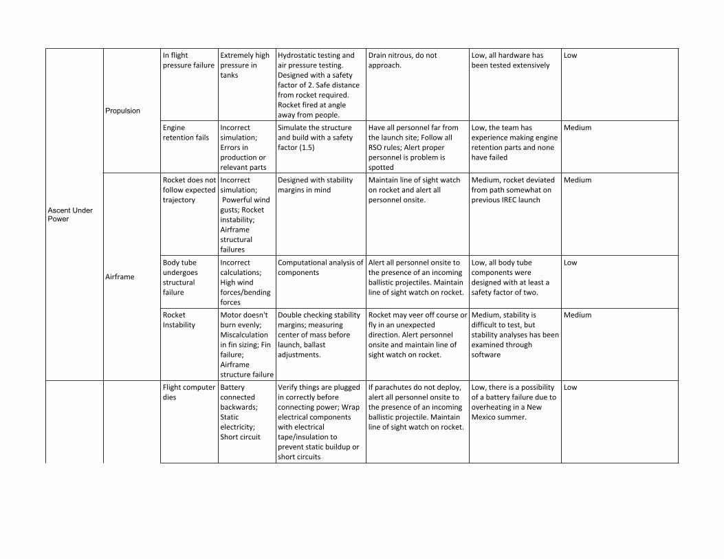
Ascent Under Power
Propulsion
In flight pressure failure
Extremely high pressure in tanks
Hydrostatic testing and air pressure testing. Designed with a safety factor of 2. Safe distance from rocket required. Rocket fired at angle away from people.
Drain nitrous, do not approach.
Low, all hardware has been tested extensively
Low
Engine retention fails
Incorrect simulation; Errors in production or relevant parts
Simulate the structure and build with a safety factor (1.5)
Have all personnel far from the launch site; Follow all RSO rules; Alert proper personnel is problem is spotted
Low, the team has experience making engine retention parts and none have failed
Medium
Airframe
Rocket does not follow expected trajectory
Incorrect simulation; Powerful wind gusts; Rocket instability; Airframe structural failures
Designed with stability margins in mind
Maintain line of sight watch on rocket and alert all personnel onsite.
Medium, rocket deviated from path somewhat on previous IREC launch
Medium
Body tube undergoes structural failure
Incorrect calculations; High wind forces/bending forces
Computational analysis of components
Alert all personnel onsite to the presence of an incoming ballistic projectiles. Maintain line of sight watch on rocket.
Low, all body tube components were designed with at least a safety factor of two.
Low
Rocket Instability
Motor doesn't burn evenly; Miscalculation in fin sizing; Fin failure; Airframe structure failure
Double checking stability margins; measuring center of mass before launch, ballast adjustments.
Rocket may veer off course or fly in an unexpected direction. Alert personnel onsite and maintain line of sight watch on rocket.
Medium, stability is difficult to test, but stability analyses has been examined through software
Medium
Decent under drogue/main
Avionics
Flight computer dies
Battery connected backwards; Static electricity; Short circuit
Verify things are plugged in correctly before connecting power; Wrap electrical components with electrical tape/insulation to prevent static buildup or short circuits
If parachutes do not deploy, alert all personnel onsite to the presence of an incoming ballistic projectile. Maintain line of sight watch on rocket.
Low, there is a possibility of a battery failure due to overheating in a New Mexico summer.
Low
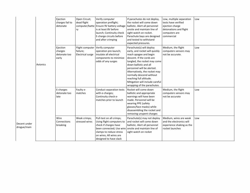
Decent under drogue/main
Avionics
Ejection charges fail to detonate
Open Circuit; dead flight computer/battery
Verify computer operation preflight; Ensure 9V battery voltage is at least 8V before launch; Continuity check E-charge circuits before and after crimping
If parachutes do not deploy, the rocket will come down ballistic. Alert all personnel onsite and maintain line of sight watch on rocket. Parachute bays are designed and tested to withstand expected pressures.
Low, multiple separation tests have verified ejection charge detonations and flight computers are commercial
Low
Ejection charges detonate too early
Flight computer failure; Electrical surge
Verify computer operation pre-launch; insulate all electrical components to minimize odds of any surges
Parachute(s) will deploy early, and rocket will quickly reach apogee and begin descent. If the cords are tangled, the rocket may come down ballistic and all personnel will be alerted. Alternatively, the rocket may normally descend without reaching full altitude. Mitigation will include careful wrapping of the parachutes.
Medium, the flight computers sensors may not be accurate.
Low
E-charges detonate too late
Faulty e-matches
Conduct separation tests with e-charges; Continuity check e-matches prior to launch
Rocket will come down ballistic and appropriate warnings will have been made. Personnel will be wearing PPE (safety glasses/face masks) while disassembling the rocket and removing unspent charges
Medium, the flight computers sensors may not be accurate
Low
Wire Connections breaking
Weak crimps; stressed wires
Pull-test on all crimps; Using flight computers to check if charges have been connected; Use wire clamps to reduce stress on wires; All wires are designed to have slack
Parachute(s) may not deploy and rocket will come down ballistic. Alert all personnel onsite and maintain line of sight watch on rocket
Medium, wires are weak and the electronics will experience shaking as the rocket launches
Low

Decent under drogue/main
Airframe
Drogue separation or main deployment fails
Any avionics issues/ejection charge issues (see avionics); Too strong connection on separation couplers; Inadequate gunpowder in ejection charge
Conducted separation tests
Rocket will come down ballistic and appropriate warnings will have been made. Maintain line of sight watch on rocket.
Medium, inability to test actual conditions of separation
Low
Seam failure on main parachute or drogue
Excessive loads on parachute; flawed stitches on parachute
Drogue deployment test; Calculation maximum load on parachute with safety factor of at least 2
If either parachute fails, rocket may come down ballistic. Alert all personnel onsite and maintain line of sight watch on rocket
Low, the load on the parachute is being spread out over all of the seams and each seam was designed with a safety factor of at least 2.
Low
Main parachute fails to unfurl
Parachute snags inside tube; Poor separation
Parachute wrapped inside deployment bag to help prevent snagging; Parachute properly folded and packed prior to launch, validated through ground tests.
Rocket may come down ballistic. Alert all personnel onsite and maintain line of sight watch on rocket
Low, ground test has validated this
Low
Main parachute tangles after deployment
Parachute folded improperly
Parachute is carefully folded prior to launch, validated through ground tests
Rocket may come down ballistic. Alert all personnel onsite and maintain line of sight watch on rocket
Medium, high number of lines leads to higher probability of tangling
Low
Main parachute deploys at apogee and drifts
Flight computer malfunction with early ejection charge ignition; Recovery system structural failure
Ground recovery tests Ensure launch is permitted at safe time by RSO. Maintain line of sight of rocket
Medium, recovery systems can be difficult to fully test in flight conditions on the ground
Low

28
Michigan Aeronautical Science Association
Appendix E: Assembly, Preflight, and Launch Checklists
See attached checklists.

Laika Launch SOP Michigan Aeronautical Science Association
IREC 2018, June 19-23 10K SRAD Liquid Launch Last Update: 5/18/2018
NOTE: RSO HAS FINAL SAY ON ALL MATTERS Purpose: Ground crew procedures at pad, fill, launch, and recovery Avionics Ground Station Set-Up
❏ Pad GSE Set-up
❏ Bring pad toolbox. Double check that you have arming keys (3/32 allen key) and adjustable wrenches.
❏ Place fuel tower and tank stand near the rail. Use flex hoses to judge distances. ❏ Make the following hose connections and turn valves to the following positions:
❏ Connect the fuel QD hose to the fuel tower ❏ Connect the tank stand nitrogen hose to the fuel tower ❏ Close all four needle valves on the tank stand panel (A,N, I, and K) ❏ Close the two ball valves on the tank stand panel (O and P) ❏ Fully open the pressure regulator on the fuel tower by turning clockwise (W) ❏ Close the 3-way ball valve on the fuel tower by turning the arrow to the “left”
position (Y) ❏ Close the needle valve on the fuel fill tower (U) ❏ Close the funnel ball valve on the top of the fuel fill tower (R) ❏ Close the vent ball valve on the top of the fuel fill tower (T)
❏ Place the closed nitrous oxide and nitrogen gas tanks into the following positions: ❏ One nitrous oxide tank into the middle slot and chain it down ❏ One nitrogen gas tank into the left slot and chain it down
❏ Make the following hose connections: ❏ Connect the nitrous tank GCA fitting to the middle CGA hose, do NOT open the
tank valve ❏ Connect the nitrogen gas tank GCA fitting to the tank stand CGA hose, do NOT
open the tank valve ❏ Connect transducer and valve harnesses to ground engine controller. ❏ Plug in and boot up engine controller. ❏ Set up wireless system and establish connection with mission control.
1
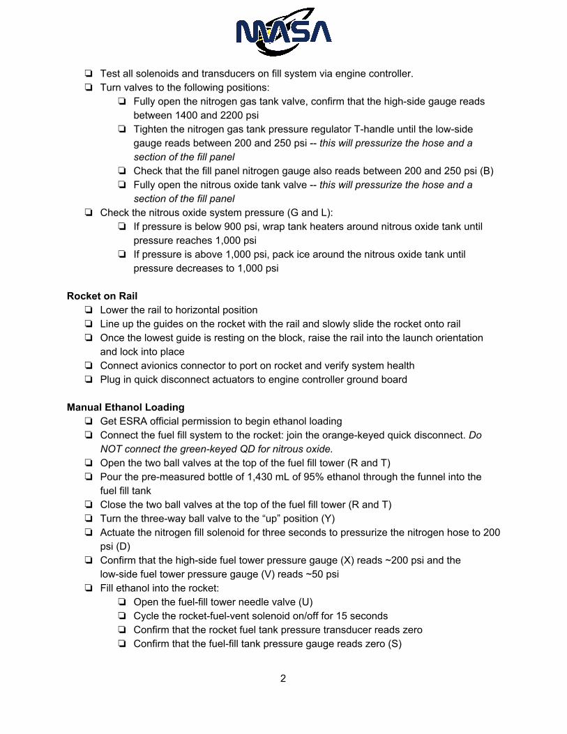
❏ Test all solenoids and transducers on fill system via engine controller. ❏ Turn valves to the following positions:
❏ Fully open the nitrogen gas tank valve, confirm that the high-side gauge reads between 1400 and 2200 psi
❏ Tighten the nitrogen gas tank pressure regulator T-handle until the low-side gauge reads between 200 and 250 psi -- this will pressurize the hose and a section of the fill panel
❏ Check that the fill panel nitrogen gauge also reads between 200 and 250 psi (B) ❏ Fully open the nitrous oxide tank valve -- this will pressurize the hose and a
section of the fill panel ❏ Check the nitrous oxide system pressure (G and L):
❏ If pressure is below 900 psi, wrap tank heaters around nitrous oxide tank until pressure reaches 1,000 psi
❏ If pressure is above 1,000 psi, pack ice around the nitrous oxide tank until pressure decreases to 1,000 psi
Rocket on Rail
❏ Lower the rail to horizontal position ❏ Line up the guides on the rocket with the rail and slowly slide the rocket onto rail ❏ Once the lowest guide is resting on the block, raise the rail into the launch orientation
and lock into place ❏ Connect avionics connector to port on rocket and verify system health ❏ Plug in quick disconnect actuators to engine controller ground board
Manual Ethanol Loading
❏ Get ESRA official permission to begin ethanol loading ❏ Connect the fuel fill system to the rocket: join the orange-keyed quick disconnect. Do
NOT connect the green-keyed QD for nitrous oxide. ❏ Open the two ball valves at the top of the fuel fill tower (R and T) ❏ Pour the pre-measured bottle of 1,430 mL of 95% ethanol through the funnel into the
fuel fill tank ❏ Close the two ball valves at the top of the fuel fill tower (R and T) ❏ Turn the three-way ball valve to the “up” position (Y) ❏ Actuate the nitrogen fill solenoid for three seconds to pressurize the nitrogen hose to 200
psi (D) ❏ Confirm that the high-side fuel tower pressure gauge (X) reads ~200 psi and the
low-side fuel tower pressure gauge (V) reads ~50 psi ❏ Fill ethanol into the rocket:
❏ Open the fuel-fill tower needle valve (U) ❏ Cycle the rocket-fuel-vent solenoid on/off for 15 seconds ❏ Confirm that the rocket fuel tank pressure transducer reads zero ❏ Confirm that the fuel-fill tank pressure gauge reads zero (S)
2
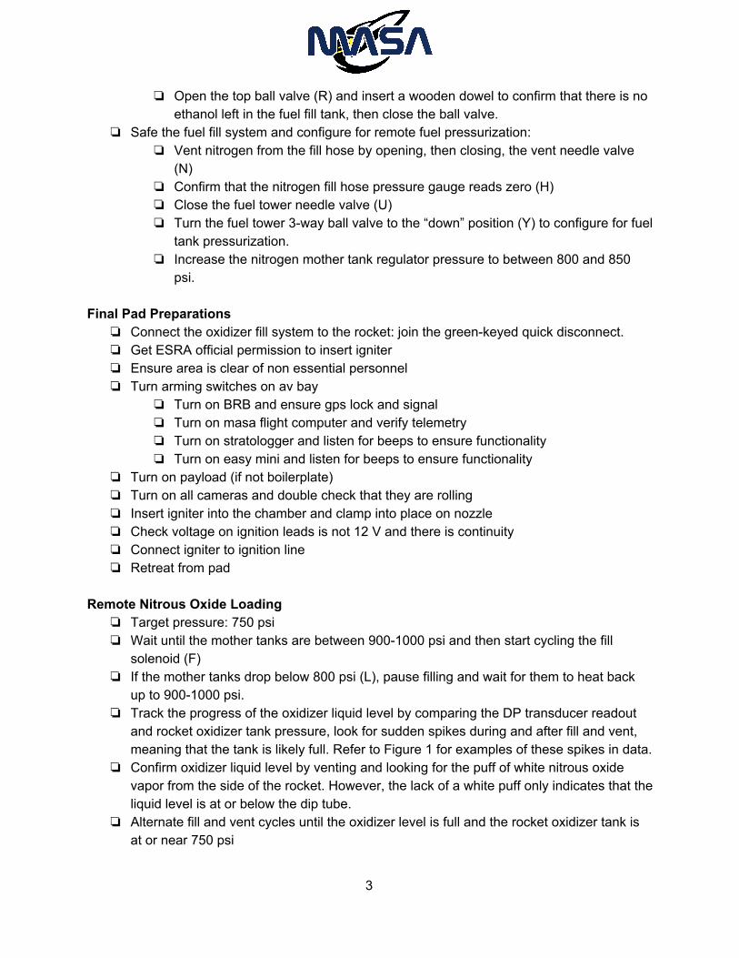
❏ Open the top ball valve (R) and insert a wooden dowel to confirm that there is no ethanol left in the fuel fill tank, then close the ball valve.
❏ Safe the fuel fill system and configure for remote fuel pressurization: ❏ Vent nitrogen from the fill hose by opening, then closing, the vent needle valve
(N) ❏ Confirm that the nitrogen fill hose pressure gauge reads zero (H) ❏ Close the fuel tower needle valve (U) ❏ Turn the fuel tower 3-way ball valve to the “down” position (Y) to configure for fuel
tank pressurization. ❏ Increase the nitrogen mother tank regulator pressure to between 800 and 850
psi. Final Pad Preparations
❏ Connect the oxidizer fill system to the rocket: join the green-keyed quick disconnect. ❏ Get ESRA official permission to insert igniter ❏ Ensure area is clear of non essential personnel ❏ Turn arming switches on av bay
❏ Turn on BRB and ensure gps lock and signal ❏ Turn on masa flight computer and verify telemetry ❏ Turn on stratologger and listen for beeps to ensure functionality ❏ Turn on easy mini and listen for beeps to ensure functionality
❏ Turn on payload (if not boilerplate) ❏ Turn on all cameras and double check that they are rolling ❏ Insert igniter into the chamber and clamp into place on nozzle ❏ Check voltage on ignition leads is not 12 V and there is continuity ❏ Connect igniter to ignition line ❏ Retreat from pad
Remote Nitrous Oxide Loading
❏ Target pressure: 750 psi ❏ Wait until the mother tanks are between 900-1000 psi and then start cycling the fill
solenoid (F) ❏ If the mother tanks drop below 800 psi (L), pause filling and wait for them to heat back
up to 900-1000 psi. ❏ Track the progress of the oxidizer liquid level by comparing the DP transducer readout
and rocket oxidizer tank pressure, look for sudden spikes during and after fill and vent, meaning that the tank is likely full. Refer to Figure 1 for examples of these spikes in data.
❏ Confirm oxidizer liquid level by venting and looking for the puff of white nitrous oxide vapor from the side of the rocket. However, the lack of a white puff only indicates that the liquid level is at or below the dip tube.
❏ Alternate fill and vent cycles until the oxidizer level is full and the rocket oxidizer tank is at or near 750 psi
3

Remote Fuel Pressurization ❏ Target pressure: 750 psi ❏ Cycle on/off the nitrogen fill solenoid (D) until the pressure reaches 750 psi. ❏ If the pressure is filled above 750 psi, open the fuel tank vent solenoid to decrease
pressure. Terminal Sequence
❏ Disconnect QDs (Fuel then Ox) ❏ Confirm visually that QDs have separated ❏ Confirm by venting that the QDs have been separated:
❏ Actuate the nitrogen fill hose vent solenoid for 5 seconds (M) ❏ The nitrogen fill hose pressure transducer (Q) should read near 0 psi ❏ The rocket fuel tank pressure should read unchanged ❏ Actuate the nitrous oxide fill hose vent solenoid for 5 seconds (E) ❏ The nitrous oxide fill hose pressure transducer (J) should read much lower than
700 psi, but not necessarily zero ❏ The rocket oxidizer tank pressure should read unchanged
❏ Set engine controller telemrates ❏ Confirm telemetry and GPS lock from Big Red Bee ❏ Confirm telemetry link with flight computer and GPS lock ❏ Wipe flight computer flash ❏ Start logging
Poll for Launch
❏ Airframe ❏ Avionics ❏ Propulsion ❏ Safety ❏ Chief ❏ ATLO
IGNITION
❏ RSO Launch Approval ❏ Check the sky for aircraft ❏ Arm engine controller ❏ Begin audible countdown ❏ Punch it, Sternie!
Post-Flight/Recovery
❏ Following liftoff, disarm engine controller ❏ Obtain location of rocket from telemetry and line-of site information ❏ Obtain official approval to proceed to landing site
4
❏ Bring cell phones (verizon), water, radios, tracking equipment, PPE (safety glasses, facemask), lipo batteries, arming key (3/32 allen key), ⅛ allen key
❏ Approach rocket carefully using appropriate PPE (safety glasses, facemask) ❏ Ensure no charges remain in recovery bays ❏ Ensure no propellants are left in tanks ❏ Carefully return rocket to base camp
5
7
MASA Liquid Engine Assembly SOP
Last Update: 3/9/18 Purpose: Pre-test assembly and post-test disassembly of the liquid engine Combustion Chamber
❏ Insert retention ring into chamber with thick section pointed inward ❏ Insert nozzle bolts, aluminum standoffs on inside, and nut, and tighten (leave bolts
reserved for connecting nitrous and fuel fill lines) ❏ Grease o-ring (039 on flight nozzle) and fit onto graphite insert. Then push insert into
steel carrier. ❏ Grease two o-rings (247 or 248) and fit onto graphite to chamber o-ring grooves ❏ Slide nozzle assembly into chamber and push until seated on retention ring. ❏ Cut phenolic liner to length (7.81 in) and grease exterior surface. Slide into chamber.
Ensure that phenolic is seated properly in grooves. ❏ Grease inner and outer manifold o-rings (030 and 033 respectively) and place into inner
sealing grooves. Place o-ring (K238) in outer ox-path groove. Be sure to use krytox grease for this step.
❏ Insert injector, tighten with injector bolts. Be careful not to unseat o-rings. Check that transducer hole in endcap and injector are aligned.
❏ Grease two o-rings (246) and put onto chamber endcap. ❏ Insert injector endcap assembly into chamber, aligning markings on endcap with
chamber, insert and tighten chamber bolts, (leave bolts reserved for connecting nitrous and fuel fill lines). The hole where the chamber pressure transducer is connected should be excluded.
❏ Double check all bolt tightnesses ❏ Attach chamber transducer to standoff then attach standoff to chamber end-cap. Teflon
both threads. ❏ Attach ox manifold transducer. Be sure to Teflon threads. ❏ Attach fuel manifold fitting to endcap using 906 o-ring to seal ❏ Attach ox pipe fitting to ox manifold using 910 o-ring to seal
Ox Tank
❏ All grease used in these steps must be krytox ❏ Grease two o-rings (246) and place over ox tank top endcap. ❏ Insert endcap into tank while being careful not to knick o-rings. Use 24 shoulder bolts to
secure endcap. ❏ Grease two o-rings (248) and place over ox tank bottom endcap. ❏ Insert endcap into tank while being careful not to knick o-rings. Use 24 shoulder bolts to
secure endcap. Start with bolts closest to ⅞ in port. ❏ Double check tightness on all bolts
❏ Attach center fuel pipe pass through to top and bottom endcaps. Ensure fittings are tefloned.
❏ Tighten down pass through fuel pipe fittings on both ends ❏ Attach ox pipe fitting to bottom of endcap using 910 o-rings ❏ Attach ox fill pipe and DP fittings to bottom endcap with 906 o-rings
Fuel Tank
❏ Grease two o-rings (246) and place over fuel tank top endcap ❏ Insert endcap into tank while being careful not to knick o-rings. Use 24 shoulder bolts to
secure endcap. ❏ Grease two o-rings (246) and place over fuel tank bottom endcap ❏ Insert endcap into tank while being careful not to knick o-rings. Use 24 shoulder bolts to
secure endcap. ❏ Double check tightness on all bolts ❏ Attach Swagelok fitting to bottom center hole of fuel tank. ❏ Attach fuel tank pressure transducer to top of fuel tank. Use teflon on the threads. ❏ Attach a 4 and a 6 AN fitting to two other ports on top of tank. Use 906 o-rings to seal.
Ox Bay
❏ Attach t-fitting to fuel manifold fitting. Ensure copper flare seal is used ❏ Attach short pipes to ox valve ❏ Attach valve assembly to ox tank but only lightly tighten. Ensure copper seal is used ❏ Bring through pipe and ox pipe into contact with respective chamber ports ensure both
connections have copper flare seals. Do not tighten fully only light hand tightening. ❏ Attach all 3 ox bay ribs at 120 degree intervals demarcated by sharpie marks on tanks.
Ribs will be numbered to denote position. Ensure ribs align up on ox and fuel bays. ❏ Rotate valve into correct orientation and tighten ox tank side fitting fully ❏ Tighten down chamber side ox and fuel pipe fittings. ❏ Attach 1600 PSI pressure transducer to rotational fitting. Ensure threads are tefloned. ❏ Cap rotational fitting. Ensure copper flare seal is used. ❏ Attach fuel manifold transducer assembly to t-fitting. Ensure copper flare seal is used.
Ensure transducer position is satisfactory. ❏ Ensure that wires are run to the correct position; particularly the potentiometer circular
connector. ❏ Attach NPT to pipe adapters on each side of DP sensor. ❏ Attach orientation pipe to dp sensor. And then attach orientation pipe to ox tank dp
fitting. Ensure sensor positioning is satisfactory. Fuel Bay
❏ Connect fuel valve to bottom of fuel tank
❏ Use ribs to align fuel and ox tanks and keep proper distance. Bring fuel through pipe up to valve and ensure proper length. Use swagelok fitting on valve to connect pipe to valve.
❏ Check measurement on dip tube then insert dip tube to appropriate depth in tank and lock it into place in diptube pass through fitting.
❏ Attach T-fitting to top of dip tube. One side should be ⅛ NPT, the other should be a swagelok nut.
❏ On swagelok side of T-fitting, attached U-shaped pipe for pressure relief valve. ❏ Attach the pressure relief valve to the end of the U-shaped pipe ❏ Teflon NPT threads on T-fitting and then attach vent solenoid to said fitting. Ensure
directionality is correct. Top Bay
❏ Connect npt External Pipe Runs
❏ Dp pipe ❏ Fuel pipe ❏ Ox pipe

Payload Assembly SOP: Acrylic Chambers
❏ Start with the 3.5”x3.5” piece and the insert the 3.5”x6” into the slots that go across on the length of the 3.5”x3.5” piece.
❏ Then take the 1.75”x6” piece and insert it perpendicular to both of the pieces so that its ridges fit into the slots that exist on both of the other pieces.
❏ Once the edges are aligned and the pieces are perpendicular to one another, apply the acrylic glue into the gap to secure them in place.
❏ Then place the last 3.5”x1.75” piece on top of the pieces, fitting it into place. Make sure the big holes line up with the bottom. Glue as well.
Cameras
❏ Screw a 2-56 bolt through both of camera mounts attaching them to one of 2-56 holes in the smallest metal piece and the one of the 2-56 holes in the bigger metal piece.
❏ Make sure the cameras are charged and have SD cards and then mount the cameras Metal Box
❏ Assemble the boxes with 5 of the sides, leaving one off one of front pieces (bigger pieces with no tapped holes)
❏ Make sure the holes in the top and bottom are aligned with how the acrylic holes will placed (read ahead to see how the holes will be aligned.
Electronics
❏ Velcro the electronic breakout board and the batteries to the bottom of the box out of the way of the thru holes (opposite side of the camera mounted on the smaller metal piece) DO NOT CONNECT THE BATTERY YET
Acrylic Chamber
❏ Place the acrylic into the box with the chambers facing outwards, on the opposite side of the camera
Metal Box
❏ Make sure the holes and on the bottom are aligned with the holes in the acrylic. ❏ Place an ematch and a petroleum jelly coated cotton ball in each of the acrylic chambers
(DO NOT CONNECT THE E-MATCHES YET) ❏ Place the front back onto the box and screw on. DO NOT FORCE THE SCREWS SO
YOU DO NOT BREAK THE ACRYLIC. Get the Payload weighted at this time
Metal Box
❏ Fit the threaded rods through the box stopping before the acrylic to put a nut on and then a nut on after the acrylic, sandwiching the acrylic at every point where the threaded rod crosses the acrylic.
❏ Connect the e-matches to the breakout board and place the heads on top of the cotton balls.
❏ Before you finish, lay the box on its side. Turn the cameras on and then plug in the battery. FROM NOW, MAKE SURE THE PAYLOAD STAYS ON ITS SIDE AND MAKE SURE YOU KNOW WHICH SIDE IS UP (THE SIDE WITH CAMERA OPPOSITE OF THE ELECTRONICS)
29
Michigan Aeronautical Science Association
Appendix F: Engineering Drawings
Attached are the engineering drawings which define the subsections of Laika. Below is the organization of
the documents and how they relate to the overall assembly. The following list of drawings is the order in which
they appear in Appendix F.
Rocket assembly
Fin
Fin can assembly
Nose cone assembly
Payload bay assembly
Payload front
Payload side
Payload bottom
Engine controller schematics
Propulsion stack assembly
Combustion chamber assembly
Injector plate
Oxidizer tank tube
Fuel tank tube
Combustion chamber tube
Oxidizer tank bottom endcap
Oxidizer tank top endcap
Fuel tank top endcap
Fuel tank bottom endcap
Chamber endcap manifold
Graphite nozzle section
Steel nozzle section
Nozzle retention ring
136.93
A A
B B
2
2
1
1
DO NOT SCALE DRAWING
LaikaSHEET 1 OF 1
UNLESS OTHERWISE SPECIFIED:
SCALE 1:30 WEIGHT:
REVDWG. NO.
ASIZE
TITLE:
NAME DATE
COMMENTS:
Q.A.
MFG APPR.
ENG APPR.
CHECKED
DRAWN
FINISH
MATERIAL
INTERPRET GEOMETRICTOLERANCING PER:
DIMENSIONS ARE IN INCHESTOLERANCES:FRACTIONALANGULAR: MACH BEND TWO PLACE DECIMAL THREE PLACE DECIMAL
APPLICATION
USED ONNEXT ASSY
PROPRIETARY AND CONFIDENTIALTHE INFORMATION CONTAINED IN THISDRAWING IS THE SOLE PROPERTY OF<INSERT COMPANY NAME HERE>. ANY REPRODUCTION IN PART OR AS A WHOLEWITHOUT THE WRITTEN PERMISSION OF<INSERT COMPANY NAME HERE> IS PROHIBITED.

12.24
6.25
11.37
3.00
9.50
.19
A A
B B
2
2
1
1
DO NOT SCALE DRAWING
finSHEET 1 OF 1
UNLESS OTHERWISE SPECIFIED:
SCALE: 1:4 WEIGHT:
REVDWG. NO.
ASIZE
TITLE:
NAME DATE
COMMENTS:
Q.A.
MFG APPR.
ENG APPR.
CHECKED
DRAWN
FINISH
MATERIAL
INTERPRET GEOMETRICTOLERANCING PER:
DIMENSIONS ARE IN INCHESTOLERANCES:FRACTIONALANGULAR: MACH BEND TWO PLACE DECIMAL THREE PLACE DECIMAL
APPLICATION
USED ONNEXT ASSY
PROPRIETARY AND CONFIDENTIALTHE INFORMATION CONTAINED IN THISDRAWING IS THE SOLE PROPERTY OF<INSERT COMPANY NAME HERE>. ANY REPRODUCTION IN PART OR AS A WHOLEWITHOUT THE WRITTEN PERMISSION OF<INSERT COMPANY NAME HERE> IS PROHIBITED.

78.00
6.35
12.24
A A
B B
2
2
1
1
DO NOT SCALE DRAWING
Motor SectionSHEET 1 OF 1
UNLESS OTHERWISE SPECIFIED:
SCALE: 1:18 WEIGHT:
REVDWG. NO.
ASIZE
TITLE:
NAME DATE
COMMENTS:
Q.A.
MFG APPR.
ENG APPR.
CHECKED
DRAWN
FINISH
MATERIAL
INTERPRET GEOMETRICTOLERANCING PER:
DIMENSIONS ARE IN INCHESTOLERANCES:FRACTIONALANGULAR: MACH BEND TWO PLACE DECIMAL THREE PLACE DECIMAL
APPLICATION
USED ONNEXT ASSY
PROPRIETARY AND CONFIDENTIALTHE INFORMATION CONTAINED IN THISDRAWING IS THE SOLE PROPERTY OF<INSERT COMPANY NAME HERE>. ANY REPRODUCTION IN PART OR AS A WHOLEWITHOUT THE WRITTEN PERMISSION OF<INSERT COMPANY NAME HERE> IS PROHIBITED.
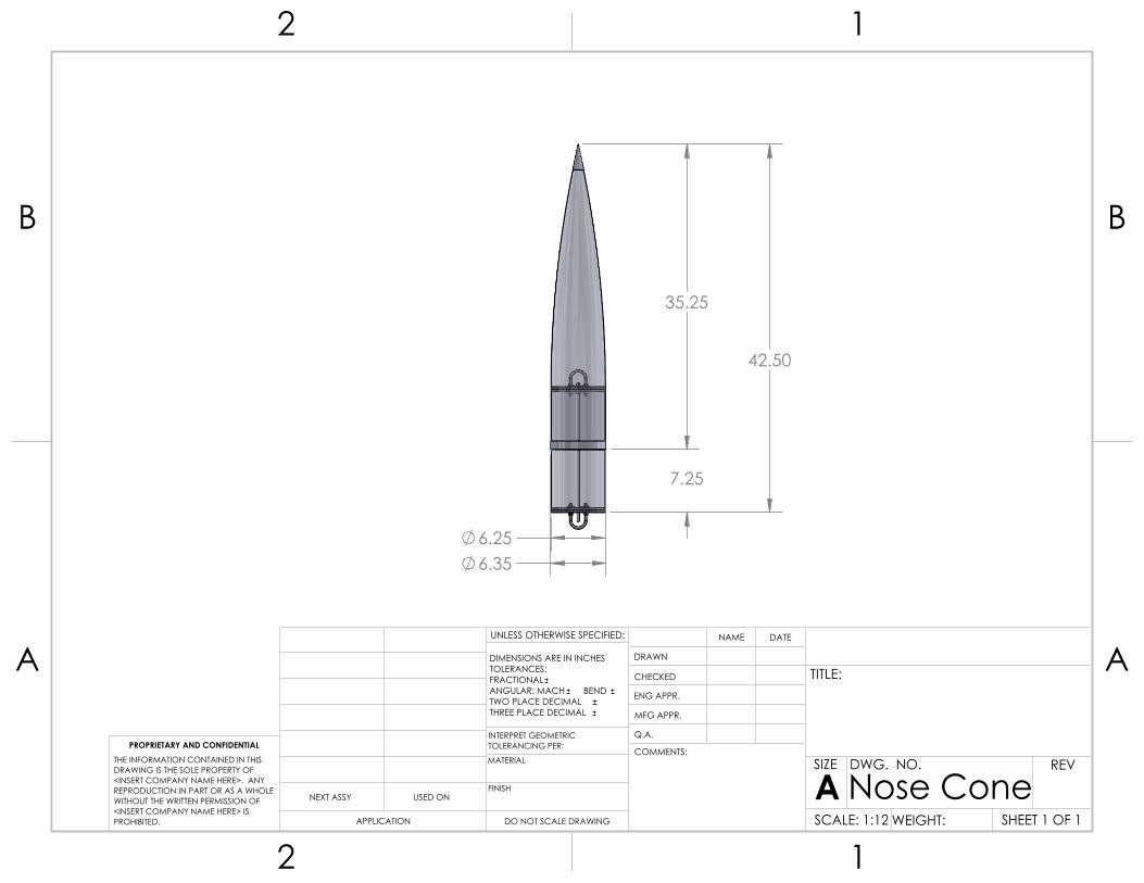
42.50
35.25
7.25
6.25 6.35
A A
B B
2
2
1
1
DO NOT SCALE DRAWING
Nose ConeSHEET 1 OF 1
UNLESS OTHERWISE SPECIFIED:
SCALE: 1:12 WEIGHT:
REVDWG. NO.
ASIZE
TITLE:
NAME DATE
COMMENTS:
Q.A.
MFG APPR.
ENG APPR.
CHECKED
DRAWN
FINISH
MATERIAL
INTERPRET GEOMETRICTOLERANCING PER:
DIMENSIONS ARE IN INCHESTOLERANCES:FRACTIONALANGULAR: MACH BEND TWO PLACE DECIMAL THREE PLACE DECIMAL
APPLICATION
USED ONNEXT ASSY
PROPRIETARY AND CONFIDENTIALTHE INFORMATION CONTAINED IN THISDRAWING IS THE SOLE PROPERTY OF<INSERT COMPANY NAME HERE>. ANY REPRODUCTION IN PART OR AS A WHOLEWITHOUT THE WRITTEN PERMISSION OF<INSERT COMPANY NAME HERE> IS PROHIBITED.

6.25
13.25
A A
B B
2
2
1
1
DO NOT SCALE DRAWING
payloadSHEET 1 OF 1
UNLESS OTHERWISE SPECIFIED:
SCALE: 1:8 WEIGHT:
REVDWG. NO.
ASIZE
TITLE:
NAME DATE
COMMENTS:
Q.A.
MFG APPR.
ENG APPR.
CHECKED
DRAWN
FINISH
MATERIAL
INTERPRET GEOMETRICTOLERANCING PER:
DIMENSIONS ARE IN INCHESTOLERANCES:FRACTIONALANGULAR: MACH BEND TWO PLACE DECIMAL THREE PLACE DECIMAL
APPLICATION
USED ONNEXT ASSY
PROPRIETARY AND CONFIDENTIALTHE INFORMATION CONTAINED IN THISDRAWING IS THE SOLE PROPERTY OF<INSERT COMPANY NAME HERE>. ANY REPRODUCTION IN PART OR AS A WHOLEWITHOUT THE WRITTEN PERMISSION OF<INSERT COMPANY NAME HERE> IS PROHIBITED.
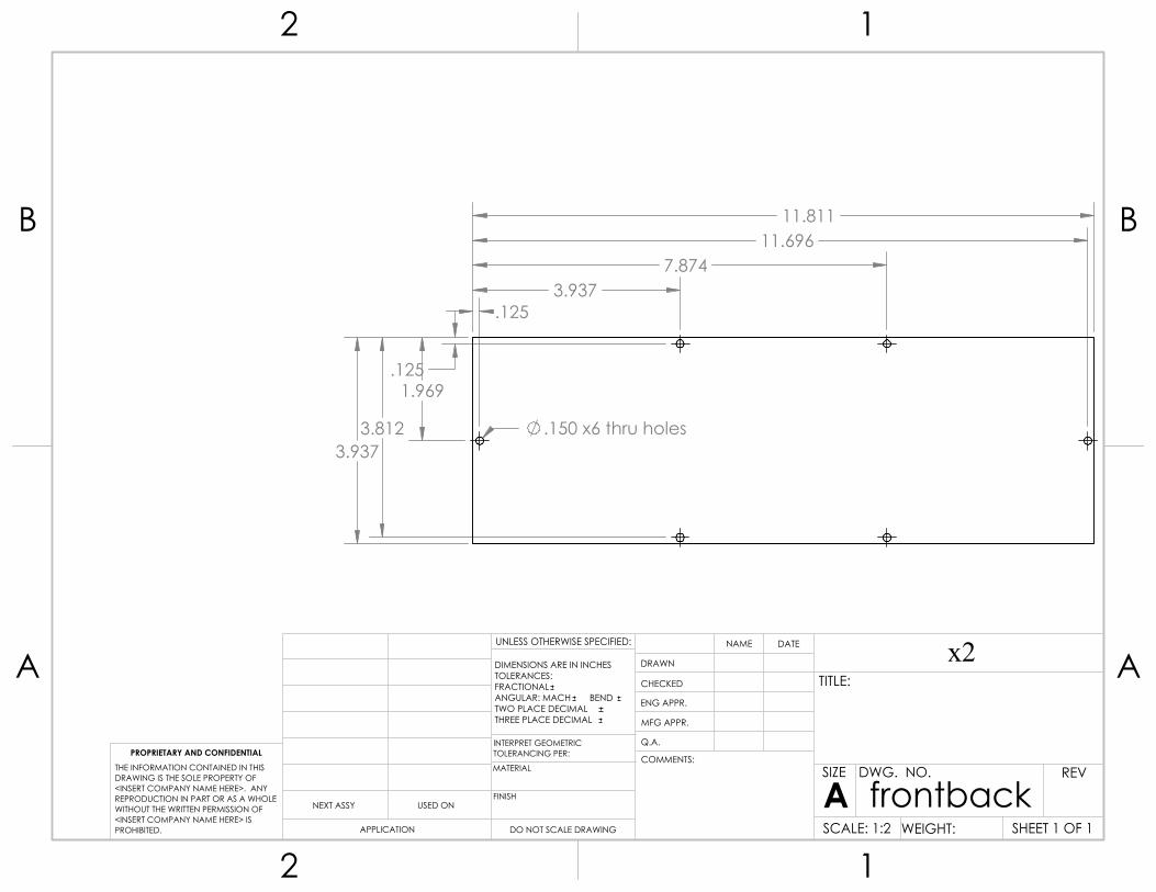
1.969 .125
.150 x6 thru holes
3.937 7.874
.125
11.696
3.812 3.937
11.811
A A
B B
2
2
1
1
DO NOT SCALE DRAWING
frontbackSHEET 1 OF 1
UNLESS OTHERWISE SPECIFIED:
SCALE: 1:2 WEIGHT:
REVDWG. NO.
ASIZE
TITLE:
x2NAME DATE
COMMENTS:
Q.A.
MFG APPR.
ENG APPR.
CHECKED
DRAWN
FINISH
MATERIAL
INTERPRET GEOMETRICTOLERANCING PER:
DIMENSIONS ARE IN INCHESTOLERANCES:FRACTIONALANGULAR: MACH BEND TWO PLACE DECIMAL THREE PLACE DECIMAL
APPLICATION
USED ONNEXT ASSY
PROPRIETARY AND CONFIDENTIALTHE INFORMATION CONTAINED IN THISDRAWING IS THE SOLE PROPERTY OF<INSERT COMPANY NAME HERE>. ANY REPRODUCTION IN PART OR AS A WHOLEWITHOUT THE WRITTEN PERMISSION OF<INSERT COMPANY NAME HERE> IS PROHIBITED.
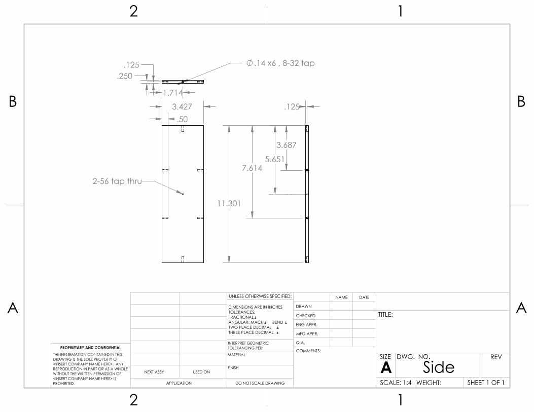
3.427 .50
2-56 tap thru
.125
1.714
.14 x6 , 8-32 tap .250
3.687
7.614
.125
11.301
5.651
A A
B B
2
2
1
1
DO NOT SCALE DRAWING
SideSHEET 1 OF 1
UNLESS OTHERWISE SPECIFIED:
SCALE: 1:4 WEIGHT:
REVDWG. NO.
ASIZE
TITLE:
NAME DATE
COMMENTS:
Q.A.
MFG APPR.
ENG APPR.
CHECKED
DRAWN
FINISH
MATERIAL
INTERPRET GEOMETRICTOLERANCING PER:
DIMENSIONS ARE IN INCHESTOLERANCES:FRACTIONALANGULAR: MACH BEND TWO PLACE DECIMAL THREE PLACE DECIMAL
APPLICATION
USED ONNEXT ASSY
PROPRIETARY AND CONFIDENTIALTHE INFORMATION CONTAINED IN THISDRAWING IS THE SOLE PROPERTY OF<INSERT COMPANY NAME HERE>. ANY REPRODUCTION IN PART OR AS A WHOLEWITHOUT THE WRITTEN PERMISSION OF<INSERT COMPANY NAME HERE> IS PROHIBITED.
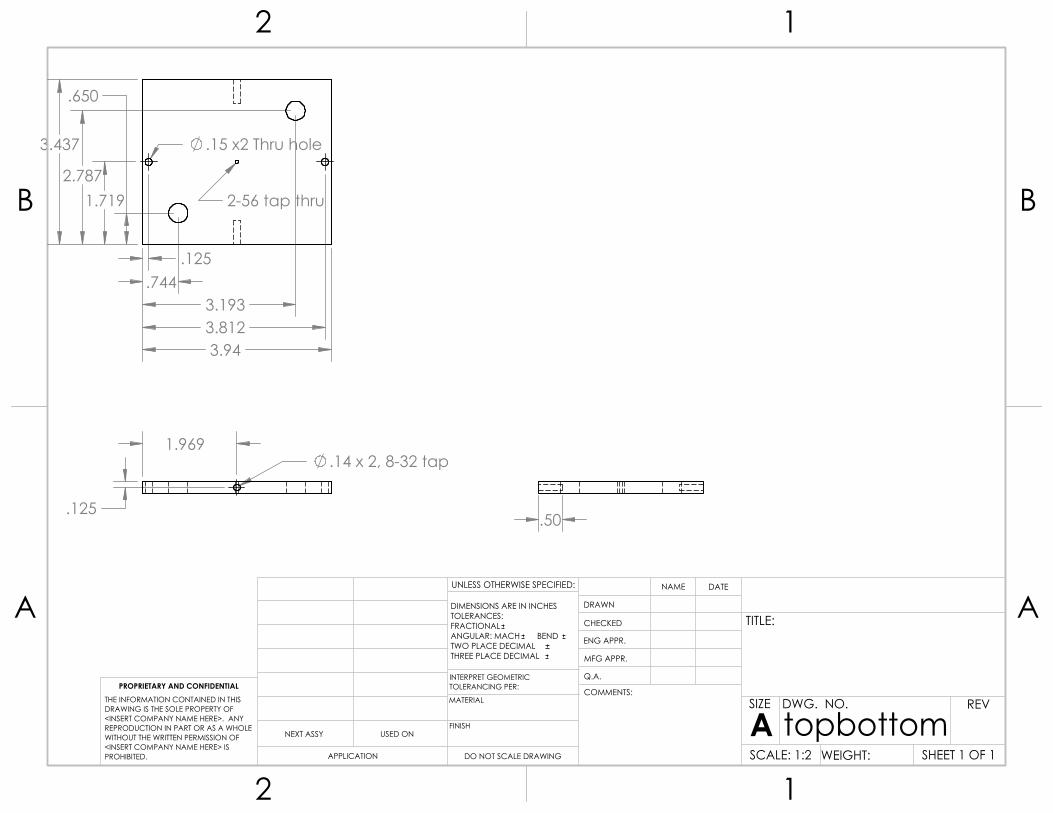
1.969 .14 x 2, 8-32 tap
.125
.15 x2 Thru hole
.125
3.812
1.719
3.437
.744
.650
3.193
2.787
3.94
2-56 tap thru
.50
A A
B B
2
2
1
1
DO NOT SCALE DRAWING
topbottomSHEET 1 OF 1
UNLESS OTHERWISE SPECIFIED:
SCALE: 1:2 WEIGHT:
REVDWG. NO.
ASIZE
TITLE:
NAME DATE
COMMENTS:
Q.A.
MFG APPR.
ENG APPR.
CHECKED
DRAWN
FINISH
MATERIAL
INTERPRET GEOMETRICTOLERANCING PER:
DIMENSIONS ARE IN INCHESTOLERANCES:FRACTIONALANGULAR: MACH BEND TWO PLACE DECIMAL THREE PLACE DECIMAL
APPLICATION
USED ONNEXT ASSY
PROPRIETARY AND CONFIDENTIALTHE INFORMATION CONTAINED IN THISDRAWING IS THE SOLE PROPERTY OF<INSERT COMPANY NAME HERE>. ANY REPRODUCTION IN PART OR AS A WHOLEWITHOUT THE WRITTEN PERMISSION OF<INSERT COMPANY NAME HERE> IS PROHIBITED.

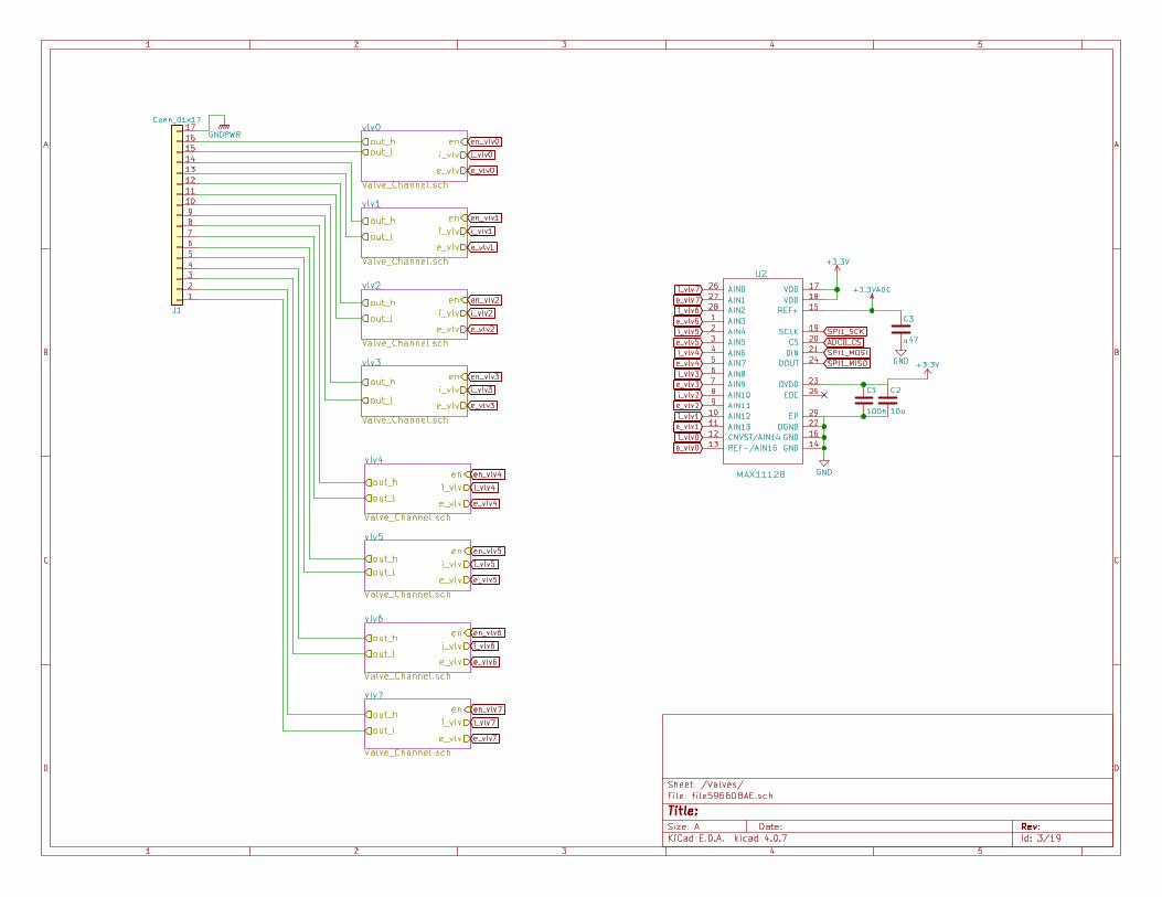


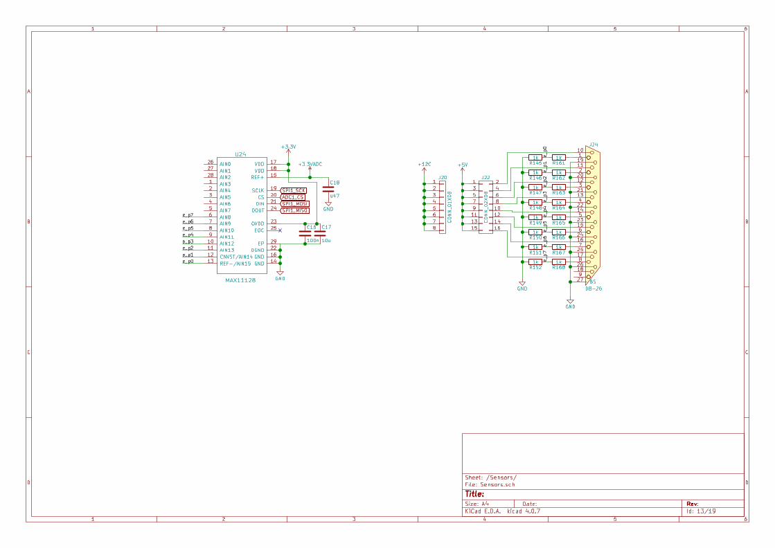


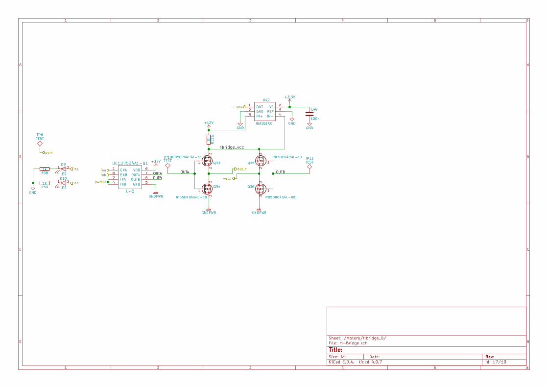

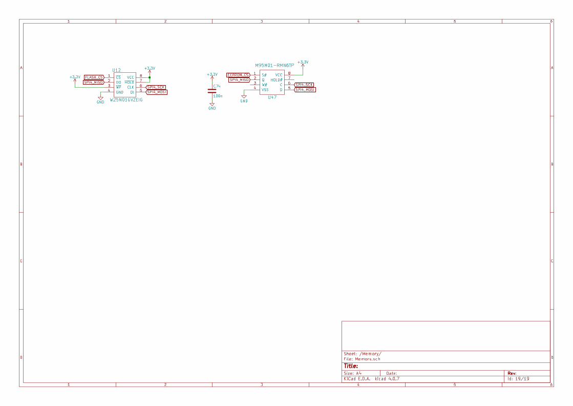

66.40
5.45
12.20 21.50 13.67
BB
SECTION B-BSCALE 1 : 5
A A
B B
4
4
3
3
2
2
1
1
Propulsion Stack
XXXSHEET 1 OF 1
X.X.XXX.XXX
UNLESS OTHERWISE SPECIFIED:
SCALE: 1:20
REVDWG. NO.
TITLE:NAME DATE
DESIGNER SIGN-OFF
DRAWNDIMENSIONS ARE IN INCHESTOLERANCES:
C
PRODUCTION SIGN-OFF
X.XXX
X.XXX
X.X.XX
X.X.XX
WEIGHT: XXX
SOLIDWORKS Educational Product. For Instructional Use Only.

13.
67
B
B
5.50
3.23
7.4
4 SECTION B-BSCALE 1 : 2.5
A A
B B
4
4
3
3
2
2
1
1
ALUMINUM XXXX
Combustion Chamber Assembly
XXXSHEET 1 OF 1
X.X.XXX.XXX
UNLESS OTHERWISE SPECIFIED:
SCALE: 1:5
REVDWG. NO.
TITLE:NAME DATE
DESIGNER SIGN-OFF
DRAWNDIMENSIONS ARE IN INCHESTOLERANCES:
X
PRODUCTION SIGN-OFF
X.XXX
X.XXX
X.X.XX
X.X.XX
WEIGHT: XXX
SOLIDWORKS Educational Product. For Instructional Use Only.
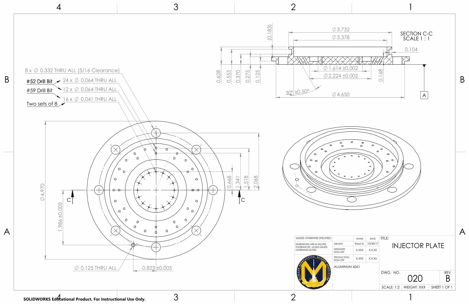
1.9
86 ±
0.00
5
0.823 ±0.005
1.5
18
2.0
68
8 x 0.332 THRU ALL (5/16 Clearance)
24 x 0.064 THRU ALL
4.
970
0.125 THRU ALL
0.6
68
16 x 0.041 THRU ALL
1.3
41
12 x 0.064 THRU ALL
CC
#52 Drill Bit#52 Drill Bit
#59 Drill Bit
Two sets of 8
3.732
0.104
3.378
0.1
25
0.2
75
0.3
70
0.5
53
0.6
28
30° ±0.50° 4.650
0.1
68
(0.1
83)
1.614 ±0.002 2.224 ±0.002
SECTION C-CSCALE 1 : 1
A
A A
B B
4
4
3
3
2
2
1
1
ALUMINUM 6061
INJECTOR PLATE
020SHEET 1 OF 1
10/30/17Keon K.
UNLESS OTHERWISE SPECIFIED:
SCALE: 1:2
REVDWG. NO.
TITLE:NAME DATE
DESIGNER SIGN-OFF
DRAWNDIMENSIONS ARE IN INCHESTOLERANCES: 0.003 UNLESSOTHERWISE NOTED
B
PRODUCTION SIGN-OFF
X.XXX
X.XXX
X.X.XX
X.X.XX
WEIGHT: XXX
SOLIDWORKS Educational Product. For Instructional Use Only.
(21.
50)
24X 0.250 ++
0.0040.001
F
F
BOLT PATTERNS ON TOP/BOTTOmMUST BE ALIGNED WITH EACH OTHER(TRY YOUR BEST)
BOLT PATTERNS ON TOP/BOTTOmMUST BE ALIGNED WITH EACH OTHER(TRY YOUR BEST)
( 5.450)
( 5.230)
5.00 STK
0.12
0.23
0.
25
1.0
0 1
.00
0.5
0 M
IN
0 0.50 MIN
20.50
SECTION F-FSCALE 1 : 2
A A
B B
4
4
3
3
2
2
1
1
ALUMINUM 6061-T6
Ox Tank Tube
032SHEET 1 OF 1
1/16/18Rory H.
UNLESS OTHERWISE SPECIFIED:
SCALE: 1:10
REVDWG. NO.
TITLE:NAME DATE
DESIGNER SIGN-OFF
DRAWNDIMENSIONS ARE IN INCHESTOLERANCES: +/- 0.01 UNLESSOTHERWISE SPECIFIED
C
PRODUCTION SIGN-OFF
X.XXX
X.XXX
X.X.XX
X.X.XX
WEIGHT: XXX
SOLIDWORKS Educational Product. For Instructional Use Only.

(12.
20)
( 5.450)
24X 0.250 ++
0.0040.001
B
B
BOLT PATTERNS ON TOP/BOTTOMMUST BE ALIGNED WITH EACH OTHERBOLT PATTERNS ON TOP/BOTTOMMUST BE ALIGNED WITH EACH OTHER
5.00 STK
( 5.450)
( 5.230)
0.225 + 0.0050.000
0.115 + 0.0050.000
0.5
0 M
IN
0 0.50 MIN
11.20
SECTION B-BSCALE 1 : 2
A A
B B
4
4
3
3
2
2
1
1
ALUMINUM 6061-T6
Fuel Tank Tube
033SHEET 1 OF 1
1/16/18Rory H.
UNLESS OTHERWISE SPECIFIED:
SCALE: 1:5
REVDWG. NO.
TITLE:NAME DATE
DESIGNER SIGN-OFF
DRAWNDIMENSIONS ARE IN INCHESTOLERANCES: +/- 0.01 UNLESSOTHERWISE NOTED
C
PRODUCTION SIGN-OFF
X.XXX
X.XXX
X.X.XX
X.X.XX
WEIGHT: XXX
SOLIDWORKS Educational Product. For Instructional Use Only.
(11.
27)
( 5.50)
24X 0.250 ++
0.0040.001
B
B
BOLT PATTERNS ON TOP/BOTTOMMUST BE ALIGNED WITH EACH OTHERBOLT PATTERNS ON TOP/BOTTOMMUST BE ALIGNED WITH EACH OTHER
( 5.500)
( 5.320)
5.00 STK
0.250 + 0.0050.000
0.160 + 0.0050.000
0.50 MIN
0 0.50 MIN
10.27
SECTION B-BSCALE 1 : 2
A A
B B
4
4
3
3
2
2
1
1
ALUMINUM 6061-T6
Chamber Tube
034SHEET 1 OF 1
1/16/18Rory H.
UNLESS OTHERWISE SPECIFIED:
SCALE: 1:5
REVDWG. NO.
TITLE:NAME DATE
DESIGNER SIGN-OFF
DRAWNDIMENSIONS ARE IN INCHESTOLERANCES: +/- 0.01 UNLESSOTHERWISE NOTED
C
PRODUCTION SIGN-OFF
X.XXX
X.XXX
X.X.XX
X.X.XX
WEIGHT: XXX
SOLIDWORKS Educational Product. For Instructional Use Only.
7/8-14 UNF THRU ALL
A
1/4 NPT THRU ALLB
9/16-18 UNF THRU ALLC
1.479 ±0.005 1.50 ±0.01
1.2
5 ±0
.01
THRU ALL9/16-18 UNF I
GG
0.3
57
0.6
91 ±
0.00
5
1.1
66
3.990 ±0.005 4.610
4.982 -0.0000.006
D
H
SECTION G-GSCALE 1 : 1
10-32 UNF 0.5500.250 0.270
x24
0.3
20
(0.0
80)
0.18
3 F
0.2
63
0.5
26
0.104E
TOLERANCES: 0.003DETAIL H
SCALE 3 : 1A A
B B
4
4
3
3
2
2
1
1
ALUMINUM 7075
Liquid Ox TankBottom Endcap
037SHEET 1 OF 1
1/7/2018Keon K.
UNLESS OTHERWISE SPECIFIED:
SCALE: 1:2
REVDWG. NO.
TITLE:NAME DATE
DESIGNER SIGN-OFF
DRAWNDIMENSIONS ARE IN INCHESTOLERANCES: 0.007 UNLESSOTHERWISE NOTED
C
PRODUCTION SIGN-OFF
X.XXX
X.XXX
X.X.XX
X.X.XX
WEIGHT: XXX
SOLIDWORKS Educational Product. For Instructional Use Only.
10-32 UNF 0.550 0.250 0.270
x24 ♦A
0.2
50
J
J
K
1.2
50
1.4
79
THRU ALL1/4 NPT ♦B
THRU ALL1/8 NPT ♦H
THRU ALL1/4 NPT ♦C
THRU ALL9/16-18 UNF J
1.250
4.586
3.500
0.3
12
0.6
46 + -0.
003
0.00
5 ♦G
4.982 -0.0000.006
I
1.0
66
SECTION J-JSCALE 1 : 1
0.2
83
0.5
66
0.103 ♦F
0.1
83 ♦
D
DETAIL VIEW K:TOLERANCES: 0.003
A A
B B
4
4
3
3
2
2
1
1
MATERIAL: Al 7075
OX TANK TOP ENDCAP
038SHEET 1 OF 1
10.3.17ethend
UNLESS OTHERWISE SPECIFIED:
SCALE: 1:1
REVDWG. NO.
TITLE:NAME DATE
DESIGNER SIGN-OFF
DRAWNDIMENSIONS ARE IN INCHESTOLERANCES: +/- 0.007
C
PRODUCTION SIGN-OFF
X.XXX
X.XXX
X.X.XX
X.X.XX
WEIGHT: XXX
SOLIDWORKS Educational Product. For Instructional Use Only.
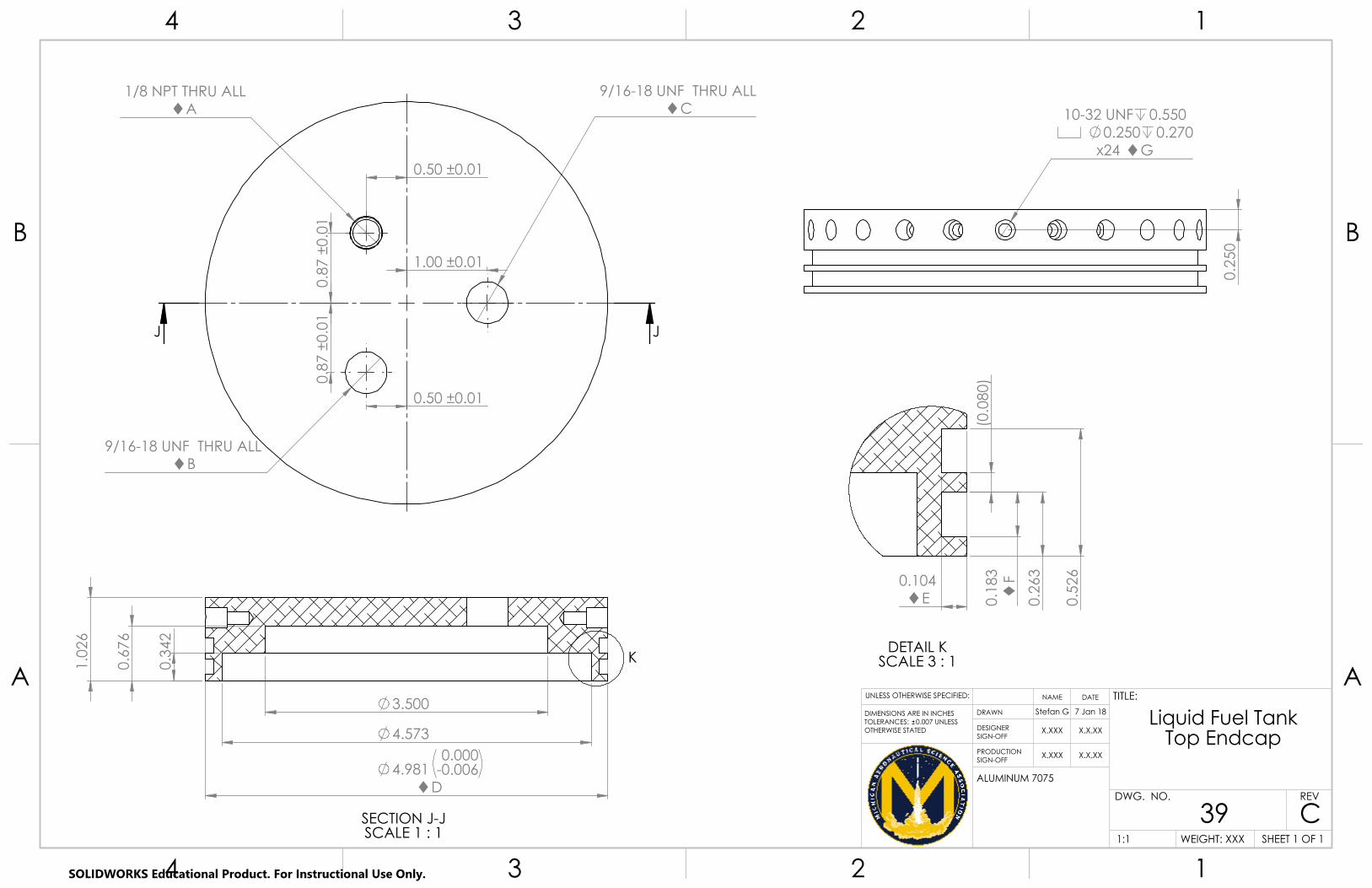
1/8 NPT THRU ALLA
0.50 ±0.01
0.8
7 ±0
.01
9/16-18 UNF THRU ALLB
9/16-18 UNF THRU ALLC
0.8
7 ±0
.01
0.50 ±0.01
1.00 ±0.01
JJ
3.500
4.573
4.981 -0.0000.006
D
1.0
26
0.6
76
0.3
42
K
SECTION J-JSCALE 1 : 1
0.104E 0.
183 F
0.2
63
0.5
26
(0.0
80)
DETAIL KSCALE 3 : 1
10-32 UNF 0.5500.250 0.270
x24 G
0.2
50
A A
B B
4
4
3
3
2
2
1
1
ALUMINUM 7075
Liquid Fuel TankTop Endcap
39SHEET 1 OF 1
7 Jan 18Stefan G
UNLESS OTHERWISE SPECIFIED:
1:1
REVDWG. NO.
TITLE:NAME DATE
DESIGNER SIGN-OFF
DRAWNDIMENSIONS ARE IN INCHESTOLERANCES: 0.007 UNLESSOTHERWISE STATED
C
PRODUCTION SIGN-OFF
X.XXX
X.XXX
X.X.XX
X.X.XX
WEIGHT: XXX
SOLIDWORKS Educational Product. For Instructional Use Only.
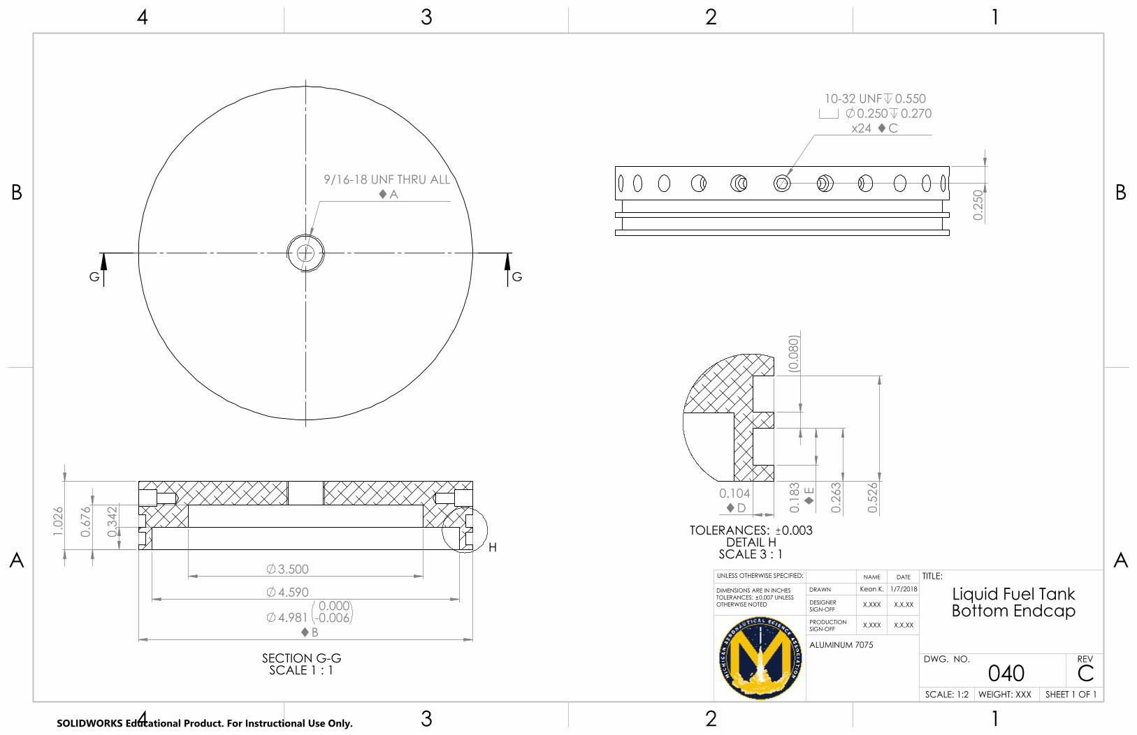
9/16-18 UNF THRU ALLA
GG
3.500
4.590
4.981 -0.0000.006
B
1.0
26
0.6
76
0.3
42
H
SECTION G-GSCALE 1 : 1
0.104D 0.
183 E
0.2
63
0.5
26
(0.0
80)
TOLERANCES: 0.003DETAIL H
SCALE 3 : 1
10-32 UNF 0.5500.250 0.270
x24 C
0.2
50
A A
B B
4
4
3
3
2
2
1
1
ALUMINUM 7075
Liquid Fuel TankBottom Endcap
040SHEET 1 OF 1
1/7/2018Keon K.
UNLESS OTHERWISE SPECIFIED:
SCALE: 1:2
REVDWG. NO.
TITLE:NAME DATE
DESIGNER SIGN-OFF
DRAWNDIMENSIONS ARE IN INCHESTOLERANCES: 0.007 UNLESSOTHERWISE NOTED
C
PRODUCTION SIGN-OFF
X.XXX
X.XXX
X.X.XX
X.X.XX
WEIGHT: XXX
SOLIDWORKS Educational Product. For Instructional Use Only.

1.479
7/8-14 UNF 0.681A
4.990B
AJAJ
Drill and Tap This Hole from This Face
Tap "THRU ALL"holes from this face
1.2
16 ±
0.00
5
0.53
5 G0.
160 F 1.620
C
2.212D
3.742E
AL AM
SECTION AJ-AJSCALE 1 : 1
A
0.049H 0.
085 I
0.1
35
DETAIL ALSCALE 2 : 1
0.104J 0.
183 K
0.2
63
0.5
21
DETAIL AMSCALE 2 : 1
1.54 ±0.01
1/8 NPT THRU ALLL
8x 5/16-24 UNF 0.550M
2.068 ±0.005
2.1
49 ±
0.00
7
1/8 NPT THRU ALLN
0.9
57 ±
0.00
7
7 x 0.041 THRU ALLO
9/16-18 UNF THRU ALLP
A A
B B
4
4
3
3
2
2
1
1
Aluminum 7075
CHAMBER ENDCAP
041SHEET 1 OF 2
1/8/2018Keon K
UNLESS OTHERWISE SPECIFIED:
SCALE: 1:1
REVDWG. NO.
TITLE:NAME DATE
DESIGNER SIGN-OFF
DRAWNDIMENSIONS ARE IN INCHESTOLERANCES: +/- 0.003 UNLESSOTHERWISE NOTED
C
PRODUCTION SIGN-OFF
X.XXX
X.XXX
X.X.XX
X.X.XX
WEIGHT: XXX
SOLIDWORKS Educational Product. For Instructional Use Only.
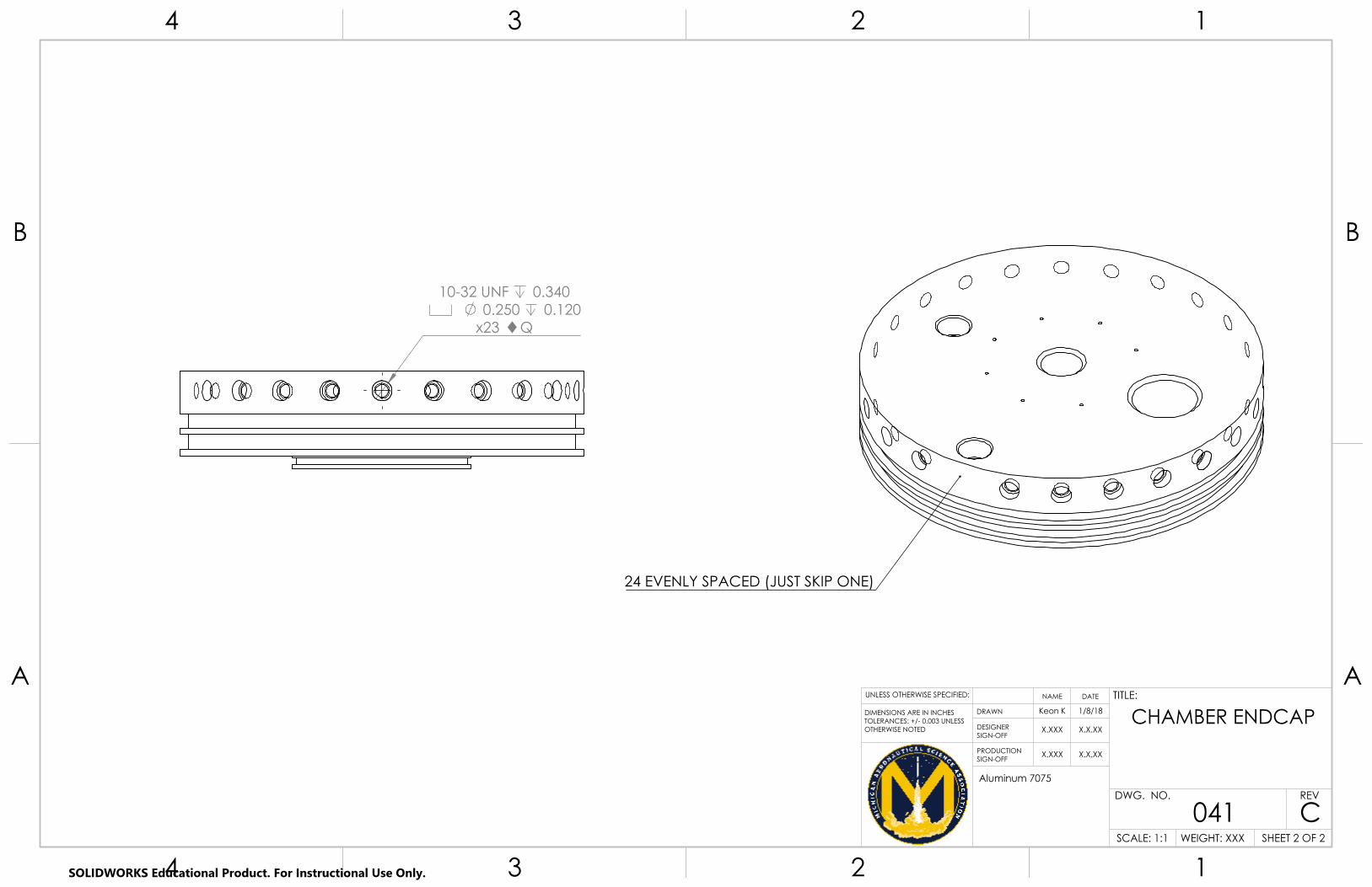
10-32 UNF 0.340 0.250 0.120
x23 Q
24 EVENLY SPACED (JUST SKIP ONE)
A A
B B
4
4
3
3
2
2
1
1
Aluminum 7075
CHAMBER ENDCAP
041SHEET 2 OF 2
1/8/18Keon K
UNLESS OTHERWISE SPECIFIED:
SCALE: 1:1
REVDWG. NO.
TITLE:NAME DATE
DESIGNER SIGN-OFF
DRAWNDIMENSIONS ARE IN INCHESTOLERANCES: +/- 0.003 UNLESSOTHERWISE NOTED
C
PRODUCTION SIGN-OFF
X.XXX
X.XXX
X.X.XX
X.X.XX
WEIGHT: XXX
SOLIDWORKS Educational Product. For Instructional Use Only.

4.980 4.650
2.873 -0.0000.003
R0.100
2.3
24
0.9
50
1.0
50
0.2
50
J
J
K
L
0.9
94
R0.700
2.000 1.467
4.440 2.229 0
.514
24.923°
1.1
76
1.1
48
15°
throat 1.419 SECTION J-JSCALE 1 : 1
0.3
42
0.7
74
1.0
24
0.1
82
0.1
82
0.104
0.104
DETAIL KTOLERANCE 0.003 0
.687
0.1
87 + 0.
005
0.00
0
0.110 -0.0000.003
DETAIL L
A A
B B
4
4
3
3
2
2
1
1
SUPERFINE GRAPHITE
15DEG_GRAPHITE_SECTION
046SHEET 1 OF 1
1/12/2018ethend
UNLESS OTHERWISE SPECIFIED:
SCALE: 1:1
REVDWG. NO.
TITLE:NAME DATE
DESIGNER SIGN-OFF
DRAWNDIMENSIONS ARE IN INCHESTOLERANCES: +/- 0.005
C
PRODUCTION SIGN-OFF
X.XXX
X.XXX
X.X.XX
X.X.XX
WEIGHT: XXX
SOLIDWORKS Educational Product. For Instructional Use Only.

2.0
16
2.1
38
2.6
53
R0.500
3.0
79
3.2
28
3.3
28
R0.100
3.476
2.546
3.125
3.215 3.869
4.980 4.690
2.740
13°
5°
J
J
L
3.226
2.000
2.2
88
2.875 + 0.0050.000
3.145
0.1
35
15°
SECTION J-JSCALE 1 : 1
20°
DETAIL LSCALE 2 : 1
A A
B B
4
4
3
3
2
2
1
1
304 SS
15DEG_STEEL_SECTION
047SHEET 1 OF 1
1/12/18ethend
UNLESS OTHERWISE SPECIFIED:
SCALE: 1:1
REVDWG. NO.
TITLE:NAME DATE
DESIGNER SIGN-OFF
DRAWNDIMENSIONS ARE IN INCHESTOLERANCES: +/- 0.005
C
PRODUCTION SIGN-OFF
X.XXX
X.XXX
X.X.XX
X.X.XX
WEIGHT: XXX
SOLIDWORKS Educational Product. For Instructional Use Only.
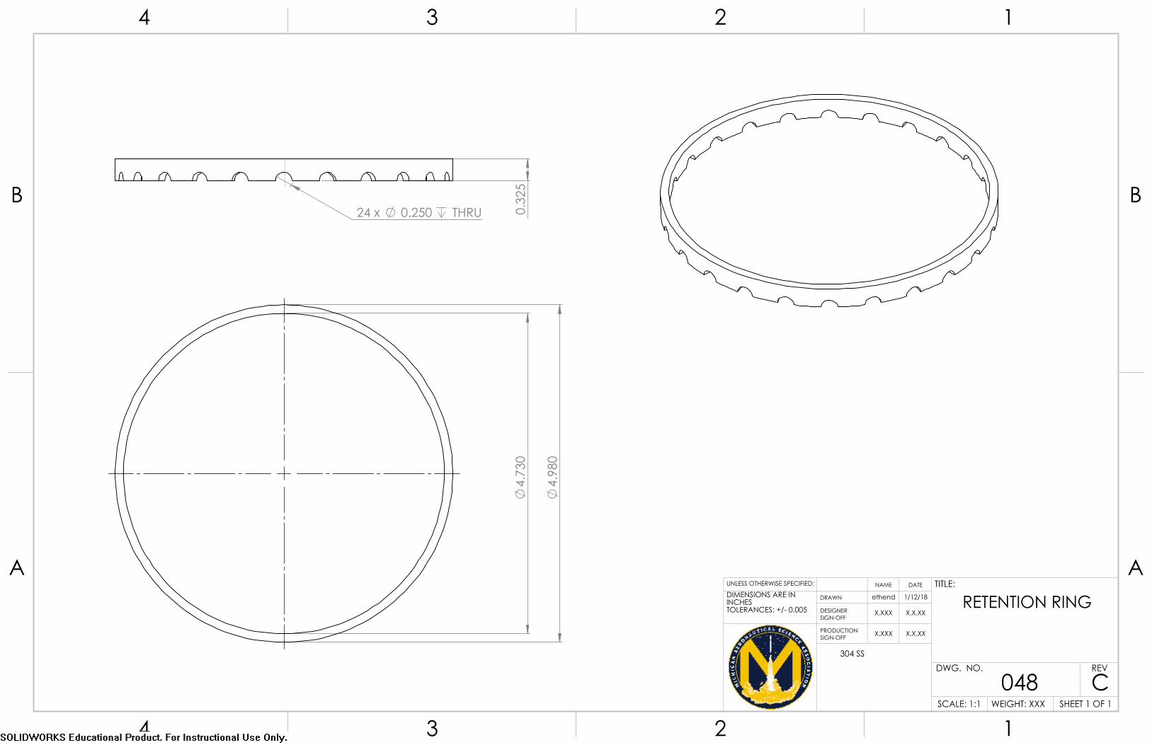
24 x 0.250 THRU 0.3
25
4.
980
4.
730
A A
B B
4
4
3
3
2
2
1
1
304 SS
RETENTION RING
048SHEET 1 OF 1
1/12/18ethend
UNLESS OTHERWISE SPECIFIED:
SCALE: 1:1
REVDWG. NO.
TITLE:NAME DATE
DESIGNER SIGN-OFF
DRAWNDIMENSIONS ARE IN INCHESTOLERANCES: +/- 0.005
C
PRODUCTION SIGN-OFF
X.XXX
X.XXX
X.X.XX
X.X.XX
WEIGHT: XXX
30
Michigan Aeronautical Science Association
Acknowledgments
The development of this project required substantial financial and organizational support. The team would like to
thank The University of Michigan College of Engineering and The Aerospace Engineering Department for their
continued support. Further, we would like to acknowledge the technical support provided the following individuals.
Professor Mirko Gamba, Faculty Advisor (University of Michigan Department of Aerospace Engineering)
Bill Fox, Wilson Student Team Project Center
Brian Kulwik, Blue Origin (Former Propulsion Lead)
Brandon Wright, Blue Origin
Ryan Crompton, Blue Origin
Chris Chartier, University of Michigan Department of Aerospace Engineering
Nick Julius, Manager (Wilson Student Team Project Center)
Chris Gordon, Director (Wilson Student Team Project Center)
The OrbitalATK Michigan recruitment team
Lastly, we would like to thank our sponsors, without them we could not pursue and achieve the success we’ve
had over the course of this project.
University of Michigan College of Engineering
University of Michigan Aerospace Engineering Department
University of Michigan Electrical and Computer Engineering
Advance Circuits
Saturn Electronics Corporation
Airborne Systems
Raytheon, Monster
Boeing
SECO
Huntsman
GraphiteStore
MiSUMi
OrbitalATK
Blue Origin
References 1Gill, G. S., and Nurick, W. H. , “Liquid Rocket Engine Injectors,” NASA SP-8089, 1976.