michigan department of transportation m … · 2 introduction in 1971, the m dot began to install...
TRANSCRIPT

MICHIGAN DEPARTMENT OF TRANSPORTATIONM�DOT
INSPECTION AND REPAIR OF HIGH-MAST LUMINAIRES (HML)
Michael C. Isola, P.E.R. L. McCrum
Research and Technology SectionMaterials and Technology Division
Research Project 91 TI-1594Research Report No. R-1342
Michigan Transportation CommissionBarton W. LaBelle, Chairman;
Richard T. White, Vice-Chairman;Robert M. Andrews, Jack L. GingrassJohn C. Kennedy, Betty Jean Awrey
Robert A. Welke, DirectorLansing, August 1996

ACTION PLAN
1. Engineering Operations Committee
A. Approve Report
2. Maintenance Division
A. Inspect all HML statewide every two years using the Procedure for theInspection of High-mast Luminaires as published by the Materials and TechnologyDivision (Included in Appendix C).
B. Remove grout that is located under the base plate of HML so thatadequate air circulation can be provided to the inside of the pole.
3. Design Division
A. Adhere to the following recommendations regarding the design andplacement of high-mast luminaire structures:
1. Tack welds used on anchor bolt nuts must no longer be used.
2. Grout under the base plate of HML must no longer be used.
3. Take the necessary steps in the geometric design of a roadway to avoidplacing HML in a ditchline. High-mast luminaires should be placed at least 10 m (33ft) from the roadway to minimize the amount of salt spray reaching the pole. Thisshould not be a problem since the required clear zone is usually equal to or greater thanthis distance.
4. Traffic and Safety Division
A. Take the necessary steps in the geometric design of a roadway to avoidplacing HML in a ditchline. High-mast luminaires should be placed at least 10 m (33ft) from the roadway to minimize the amount of salt spray reaching the pole. Thisshould not be a problem since the required clear zone is equal to or greater than thisdistance.

2
INTRODUCTION
In 1971, the M�DOT began to install high-mast lighting systems at high trafficvolume interchanges and major bridges in an effort to improve nighttime visibility.High-mast lighting systems, commonly called high-mast luminaires (HML), providea wide spread uniform distribution of light better defining interchange geometryresulting in improved capacity and reduced number of accidents. High-mast luminairesare 24.4 to 30.5 m (80 to 100 ft) tall lighting structures assembled by telescoping ortransversely welding three to four individual sections. The cross-section of the polesare normally circular or 12-sided. Each HML pole is topped with a fixture ringcontaining four to eight individual lighting heads. The M�DOT maintains a populationof 338 HML at 37 locations statewide (as of 1994) with over 71% of these installationsin the Metro district. The 224 HML erected before 1981 were fabricated using A-588weathering steel while the 103 HML erected after 1981 were fabricated using A-572galvanized steel.
In late 1991, the Structural Research Unit initiated a project with the objectiveof determining the overall condition of Michigan’s high-mast luminaire structures.Two hundred twenty-four of M�DOT's high-mast luminaire structures were made ofA-588 weathering steel now ranging in age from 10 to 20 years old. This factor,combined with reports from the Maryland Department of Transportation concerningcorrosion and cracking of their A-588 weathering steel HML poles, provided the basisfor initiating this technical investigation. Subsequent reports from the states of Indianaand Illinois documenting their experiences with corrosion and cracking of A-588weathering steel HML poles prompted the unit to refine and intensify its inspection.
1992 INSPECTION RESULTS
In 1992, the Structural Research Unit inspected a representative number ofHML. This involved an extensive physical inspection of one HML per interchange anda visual inspection of every fifth HML. If any problems were discovered, every polein the interchange was given visual inspections. We feel this procedure worked wellto discover problem areas with our limited manpower. The inspections focused onseveral characteristics and problem areas. A complete summary of these areas is listedin Tables 1 through 5, which document all the locations, characteristics, and problemareas encountered during the inspection process. The following is a general overviewof the tabulated information:
Table 1: A list of locations, job numbers, manufacturers and specific poleinformation throughout the state (last updated on 02/28/93).
Table 2: A summary of twelve sided high-mast luminaire characteristics.
Table 3: A summary of twelve sided high-mast luminaire problems thatwere documented in the field.

3
Table 4: A summary of Union Metal (circular) high-mast luminairecharacteristics.
Table 5: A summary of Union Metal high-mast luminaire problems.
PROBLEM AREAS
Five problem areas were noted during the Structural Research Unit inspections:
1. Cracks in the longitudinal weld:
It was found that 19 of 71 (27%) A-588 HML fabricated by the Union MetalCorporation have cracks in the longitudinal weld. One crack was found in thelongitudinal weld away from the telescoping end. The crack, shown in Figure 1, was430 mm (17 inches) long. Since we could not confidently locate the crack tip with adye penetrant test or ultrasonic test, the pole was removed. Eighteen of the cracks arelocated in the weld at the telescoping joint. Each telescoping joint ranges between 600mm and 900 mm (2 and 3 feet), depending on the height of the structure. Cracks werefound at the first and/or second telescoping joint and were between 24 mm and 432mm (1 and 12 inches) in length (See Figure 2). A repair procedure was developed forthe 18 defective Union Metal HML and is discussed in detail later in this report.
The crack extensions are believed to be the result of stress corrosion cracking(SCC). Stress corrosion cracks occur when the existing stress intensity factor is greaterthan the materials SCC threshold stress intensity factor and a suitable with a corrosivemedian is present, a moist chloride environment in the case. The stress intensity factoris a measure of the magnitude of the elastic-stress field for a given applied stress, crackshape, size, orientation, and structural configuration. Tensile stresses are created byresidual stresses, which result from the manufacturing process. Additional stress isapplied by radial pressure in the telescoping joint from the weight of the pole and windloads.
2. Non-full penetration weld in the telescoping joint area:
Partial penetration welds in the telescoping joint area were found at 16interchanges (146 HML) where full penetration welds are currently specified.Telescoping joint weld areas are currently required to have a 100 percent (full)penetration weld according to the M�DOT specifications and the 1985 AASHTOStandard Specifications for Structural Supports for Highway Signs, Luminaires andTraffic Signals. This problem was found with all 71 Union Metal HML as well as theother 75, A-588 weathering steel and A-572 galvanized steel, 12-sided structures thatwere produced by other manufacturers. Partial penetration welds were detected byultrasonically testing a representative sample of HML at each interchange in thetelescoping joint weld area. Partial penetration welding can contribute to increasedlocal stresses and stress intensity factors in these critical areas, increasing theprobability of cracking as discussed in problem area (1) above.
4
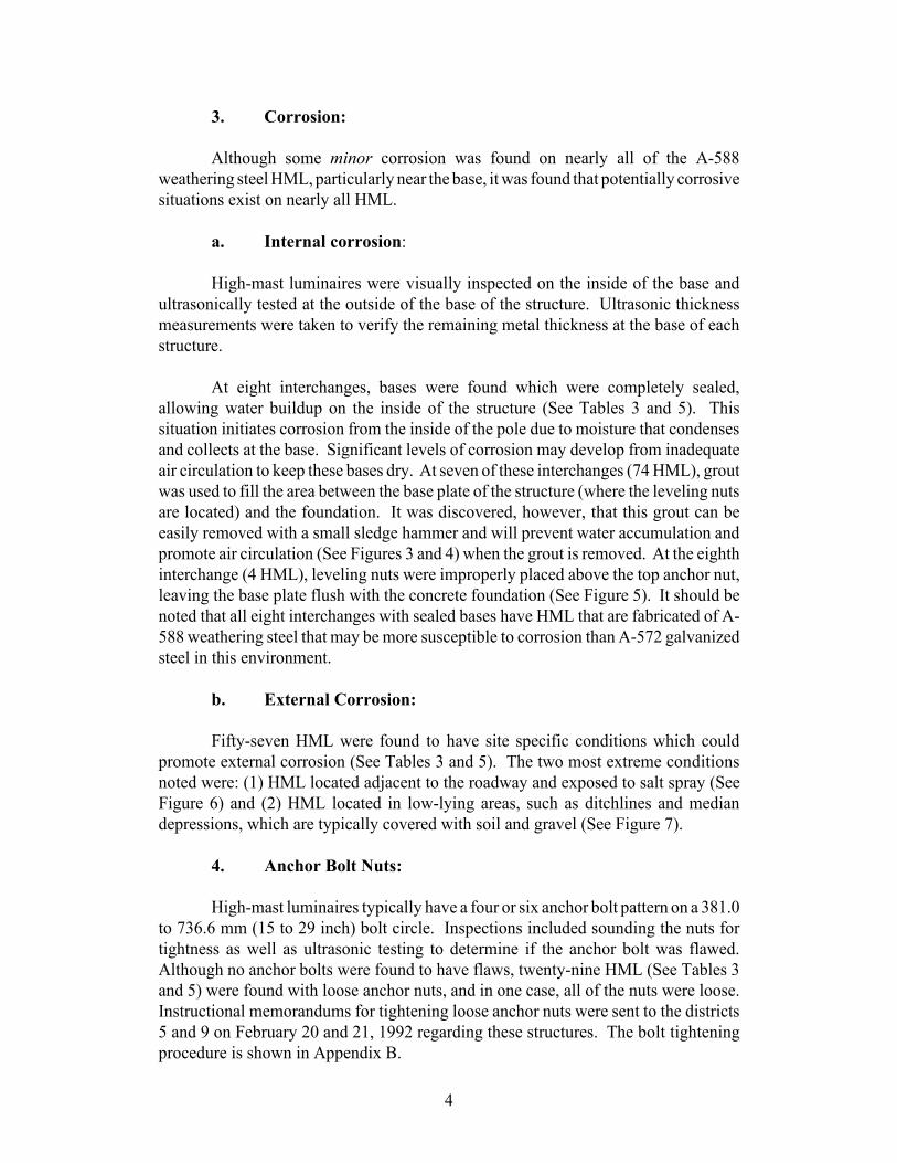
3. Corrosion:
Although some minor corrosion was found on nearly all of the A-588weathering steel HML, particularly near the base, it was found that potentially corrosivesituations exist on nearly all HML.
a. Internal corrosion:
High-mast luminaires were visually inspected on the inside of the base andultrasonically tested at the outside of the base of the structure. Ultrasonic thicknessmeasurements were taken to verify the remaining metal thickness at the base of eachstructure.
At eight interchanges, bases were found which were completely sealed,allowing water buildup on the inside of the structure (See Tables 3 and 5). Thissituation initiates corrosion from the inside of the pole due to moisture that condensesand collects at the base. Significant levels of corrosion may develop from inadequateair circulation to keep these bases dry. At seven of these interchanges (74 HML), groutwas used to fill the area between the base plate of the structure (where the leveling nutsare located) and the foundation. It was discovered, however, that this grout can beeasily removed with a small sledge hammer and will prevent water accumulation andpromote air circulation (See Figures 3 and 4) when the grout is removed. At the eighthinterchange (4 HML), leveling nuts were improperly placed above the top anchor nut,leaving the base plate flush with the concrete foundation (See Figure 5). It should benoted that all eight interchanges with sealed bases have HML that are fabricated of A-588 weathering steel that may be more susceptible to corrosion than A-572 galvanizedsteel in this environment.
b. External Corrosion:
Fifty-seven HML were found to have site specific conditions which couldpromote external corrosion (See Tables 3 and 5). The two most extreme conditionsnoted were: (1) HML located adjacent to the roadway and exposed to salt spray (SeeFigure 6) and (2) HML located in low-lying areas, such as ditchlines and mediandepressions, which are typically covered with soil and gravel (See Figure 7).
4. Anchor Bolt Nuts:
High-mast luminaires typically have a four or six anchor bolt pattern on a 381.0to 736.6 mm (15 to 29 inch) bolt circle. Inspections included sounding the nuts fortightness as well as ultrasonic testing to determine if the anchor bolt was flawed.Although no anchor bolts were found to have flaws, twenty-nine HML (See Tables 3and 5) were found with loose anchor nuts, and in one case, all of the nuts were loose.Instructional memorandums for tightening loose anchor nuts were sent to the districts5 and 9 on February 20 and 21, 1992 regarding these structures. The bolt tighteningprocedure is shown in Appendix B.

5
Tack-welded anchor bolt nuts, for the purpose of locking the nut to the anchor
rod and base, were also found on most of the HML (see Figure 8; Tables 3 and 5).Tack welds create high stress concentrations between the anchor nut and base andeventually break loose, therefore, tack welds must no longer be used.
5. Bending:
Although nearly all HML inspected did exhibit some minor bending creatingout-of-vertical alignment (typically 0.30 to 0.61 meters (1 to 2 feet) near the top of thepole, four HML were found to have bending in excess of 1.22 meters (4 feet) (SeeFigure 9). These structures were the first installed by M�DOT and have a significantlysmaller cross-section at the top of the structure than the remaining HML population.This bending is not critical at this time, however, these HML may be more susceptibleto weld cracks due to high tensile stress in the telescoping joint areas and should beclosely monitored.
1994 INSPECTION RESULTS
In 1994, M&T’s Structural Services Unit also performed an inspection of allHML in Michigan. Their inspection centered on the base of the HML and highlightedmany of the problem areas found during the Structural Research Unit's inspection in1992.
The Structural Services Unit inspection revealed the following areas of concern:
1. Gaps between the leveling nut and high-mast luminaire base plate.
2. Loose leveling and top nuts. Several nuts were found to be loose andmanual tightening was conducted in each case. However, some nuts would not turn.
3. Anchor bolts out of plumb.
4. Anchor bolts not fully engaged into nut, leaving the bolt’s top below thetop surface of the nut.
5. Washers missing.
6. Nuts and washers tack welded to the base plate (many tack welds werecracked).
7. Rodent screens missing or badly damaged.
8. Grout under the base plate inhibiting inspection of leveling nuts andholding moisture.
6
9. Anchor bolts and nuts were noted with little or no galvanizingremaining.
These findings were sent to the Maintenance Division's Statewide OperationsEngineer on August 24, 1994, (see Appendix A).
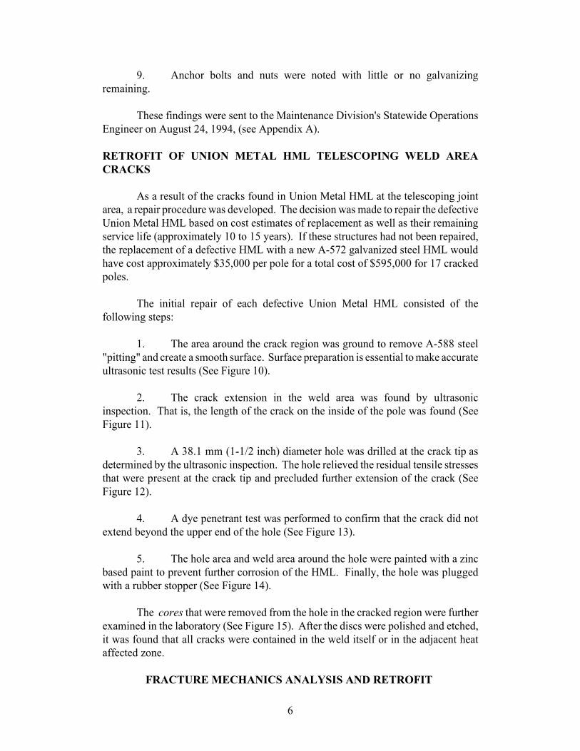
RETROFIT OF UNION METAL HML TELESCOPING WELD AREACRACKS
As a result of the cracks found in Union Metal HML at the telescoping jointarea, a repair procedure was developed. The decision was made to repair the defectiveUnion Metal HML based on cost estimates of replacement as well as their remainingservice life (approximately 10 to 15 years). If these structures had not been repaired,the replacement of a defective HML with a new A-572 galvanized steel HML wouldhave cost approximately $35,000 per pole for a total cost of $595,000 for 17 crackedpoles.
The initial repair of each defective Union Metal HML consisted of thefollowing steps:
1. The area around the crack region was ground to remove A-588 steel"pitting" and create a smooth surface. Surface preparation is essential to make accurateultrasonic test results (See Figure 10).
2. The crack extension in the weld area was found by ultrasonicinspection. That is, the length of the crack on the inside of the pole was found (SeeFigure 11).
3. A 38.1 mm (1-1/2 inch) diameter hole was drilled at the crack tip asdetermined by the ultrasonic inspection. The hole relieved the residual tensile stressesthat were present at the crack tip and precluded further extension of the crack (SeeFigure 12).
4. A dye penetrant test was performed to confirm that the crack did notextend beyond the upper end of the hole (See Figure 13).
5. The hole area and weld area around the hole were painted with a zincbased paint to prevent further corrosion of the HML. Finally, the hole was pluggedwith a rubber stopper (See Figure 14).
The cores that were removed from the hole in the cracked region were furtherexamined in the laboratory (See Figure 15). After the discs were polished and etched,it was found that all cracks were contained in the weld itself or in the adjacent heataffected zone.
FRACTURE MECHANICS ANALYSIS AND RETROFIT
7
METHODOLOGY
Fracture Mechanics Summary
The cracking is apparently the result of major defects in the longitudinal weldscombined with a high residual stress field that allows stress corrosion cracking (SCC)to occur. Such cracking is not normally a problem for weathering steels since the stressnecessary for initiation do not normally occur. Stress studies performed by the IllinoisDepartment of transportation indicate that the material used in making some of thepoles was cold worked to the point that higher than normal residual stresses have beenleft adjacent to the weld area. This in turn allows smaller defects (than would otherwisehave been the case) to create the effectively greater stress intensity factors necessaryfor SCC.
The stress intensity factor necessary for SCC is of roughly the same magnitudeas that necessary for unstable crack growth in weathering steel sections that are mostsusceptible to fracture (i.e., thicker sections with higher constraint, more dynamicloading rates, etc). Understandably there was some concern about the potential forunstable fracture of our own structures.
We decided to provide clamps to go around the poles at the cracked areas tocompensate for the material lost. This action would also reduce the stress in theblunted crack tip area since the tensile force applied with the clamps imposes acompensating compressive field in the underlying pole material. The stress reductionwill reduce the stress intensity at the repaired crack tip and, therefore, the likelihood offuture cracking. The clamps also effectively reduce the seriousness of any reoccurrenceof cracking by effectively changing the existing edge cracks to a configuration morelike a center or through thickness crack. A center crack requires roughly twice thecrack extension, at the same stress level, to achieve the same stress intensity factor asan edge crack. This means that any reoccurrence of cracking, must progress almosttwice as far before possessing the same possible danger (from a fracture mechanicsviewpoint) as the original cracks. Fracture mechanics and existing field experiencesuggest that a crack on a repaired lap joint might grow up to as much as 305 mm (12inches) (beyond the repair clamps) before becoming a potential fracture risk.
Collar Design and Installation
The Structural Research Unit designed a 100 mm (4 inch) wide by 6 mm (0.25inch) thick collar that wrapped around the area of the crack to replace lost crosssection, as well as, reduce the stress intensity in the area of the blunted crack. Thecollar was constructed of A-588 weathering steel to maintain compatibility with theexisting structure and help eliminate the need for future maintenance. The collar’s 25mm (1 inch) diameter A325 Type 3 bolts and high strength connection lugs allowed usto tighten the bolts to 133 kN (30,000 pounds), thus applying a circumferential or hoopstress of approximately 207 Mpa (30 ksi) into the pole. This load was chosen becauseit provides a desired amount of compressive stress across the crack, minimizes the

8
future corrosion between the collar and HML, and still allows reserve capacity for anywind loads. The A325 Type 3 Bolts used were first strength tested in a 10° and 20°wedge test according to ASTM F606 then additional bolts were calibrated in askidmore for the desired tension. We positioned the bolts perpendicular to the cracksurface as near as possible (see Figures 16 and 17).
All eighteen of the defective Union Metal HML were repaired by the StructuralResearch Unit. Tension in bolts of several initial installations were checked and foundto be sustaining the desired load. Site specific information for each repair is listed inTable 6.
CONCLUSIONS
Because of the problems shown in this report and resulting repairs, aninspection program has been developed to ensure the integrity of both the repaired andunrepaired HML for their remaining service life. An inspection procedure wasdeveloped and is shown in Appendix C. The procedure details the necessary steps thatmust be taken to prevent or recognize future problems with the HML population. Tohelp provide consistent inspections, an evaluation form is also provided in AppendixD.
RECOMMENDATIONS
Based on the inspection of these poles, we recommend the following:
1. Maintenance Division
A. Inspect all HML statewide every two years using the Procedurefor the Inspection of High-mast Luminaires as published by the Materials andTechnology Division (Included in Appendix C).
B. Remove grout that is located under the base plate of HML sothat adequate air circulation can be provided to the inside of the pole.
2. Design Division
A. Adhere to the following recommendations regarding the designand placement of high-mast luminaire structures:
1. Tack welds used on anchor bolt nuts must no longer be used.
2. Grout under the base plate of HML must no longer be used.
3. Take the necessary steps in the geometric design of a roadwayto avoid placing HML in a ditch line. High-mast luminaires should be placed at least10 m (33 ft) from the roadway to minimize the amount of salt spray reaching the pole.
9
This should not be a problem since the required clear zone is usually equal to or greaterthan this distance.
3. Traffic and Safety Division
A. Take the necessary steps in the geometric design of a roadwayto avoid placing HML in a ditch line. High-mast luminaires should be placed at least10 m (33 ft) from the roadway to minimize the amount of salt spray reaching the pole.This should not be a problem since the required clear zone is equal to or greater thanthis distance.

TABLES

FIGURES

APPENDIX A

APPENDIX B

31
HIGH-MAST LUMINAIRE ANCHOR BOLT TIGHTENING PROCEDURE
The tightening shall be accomplished using a multiple pass procedure,including separate passes for snugging and tightening. Full tightening shall not be doneall at one time. No more than one nut shall be removed at any one time. Anchor boltsmust have full thread engagement on the nut to accomplish the tightening. Any boltsthat do not have full thread engagement on the nut shall be tightened to a snug tightcondition only.
Procedure:
1. Determine the anchor bolt diameter and the number of threads per inchto compute the thread pitch.
2. Lightly wire brush the exposed threads to remove grit and debris thatwould interfere with removal of the nut.
3. All top nuts and leveling nuts (bottom nuts) shall be brought to a snugtight condition before removing the first nut. Some nuts are tack welded to the baseplate. Remove the tack weld by grinding and avoid damaging the base plate and nut.Spray the ground surface with cold galvanizing after the tightening operation iscomplete. A snug tight condition is defined as the tightness attained by the full effortof a person using a wrench with a length equal to 14 times the diameter of the anchorbolt. The full effort required to achieve a snug tight condition, must be applied as closeto the end of the wrench as possible. Pull firmly, by leaning back and using your entirebody weight (brace your feet to prevent slipping) on the end of the wrench until the nutstops rotating. Check tightness with repeated passes. Use a minimum wrench lengthof 450 mm (18 inches).
4. Remove the top nut and washer of one bolt (some structures will nothave washers). If a washer is missing under the top nut, install new flat washeraccording to the material type stated in step 5. Wire brush off any additional grit ordebris on the anchor bolt. (See Table 1 for maximum torque values).
5. Generously apply beeswax or the equivalent to the top nut bearing faceand the top nut internal threads prior to replacement on the anchor bolt. Tighten the topnut to a snug tight condition as defined in step 3 above. If any gaps exist between thetop nut and the base plate, a beveled washer shall be added between the nut washer andthe base plate to eliminate the gap. If the structure is galvanized steel, the beveledwasher shall be stainless steel Type 304. If the structure is A588 weathering steel, thebeveled washer shall be made from material according to ASTM F436 Type 3.
6. Repeat steps 4 and 5 until all bolts and nuts have been lubricated andtightened to a snug tight condition. The sequence of snugging shall be such that the

32
opposite side nut, to the extent possible, shall be subsequently tightened until all thenuts in the pass have been snugged.
7. Check to make sure all of the leveling nuts are in contact with the baseafter all the top nuts have been snug tightened. If any gap exists between any levelingnut and the base plate, bring the nut into full bearing with the base plate. This mayrequire the removal of a rodent screen. If a rodent screen does exist, it must bereinstalled after the tightening procedure is complete and reattached with galvanizedsteel ties.
8. Mark each nut and anchor bolt combination with a felt pen in order tovisually verify the proper amount of rotation needed.
9. Using a hydraulic wrench, rotate all top nuts an additional portion of aturn in accordance with Table 1. The total additional turning of the nuts shall beaccomplished by tightening all nuts in two separate passes of equal incremental turns(i.e., 1/16 or 1/12 turn each pass). The sequence of nut tightening in each pass shall besuch that the opposite side nut, to the extent possible, shall be subsequently tighteneduntil all the nuts in that pass have been turned. There shall be no rotation of theleveling nut during top nut tightening. See Table 1 for maximum permissible torquevalues.
TABLE 1 (English Unit Bolts Shown Only)
Bolt Diameterinch
Thread Pitch Total TurnRequired
*MaximumPermissible Torque
(ft/lb)
*MaximumPermissible Torque(N*M) Joules
1 -8 UN 1/3 500 680
1 -8 UNC 1/3 500 680
1 1/4 -8 UN 1/3 900 1220
1 1/4 -7 UNC 1/3 900 1220
1 1/2 -8 UN 1/3 1600 2170
1 1/2 -6 UNC 1/6 1600 2170
1 3/4 -8 UN 1/3 2600 3530
1 3/4 -5 UNC 1/6 2600 3530
2 -8 UN 1/3 4000 5420
2 -4 1/2 UNC 1/6 4000 5420
2 1/2 -8 UN 1/3 7800 10580
2 1/2 -4 UNC 1/6 7800 10580

33
*This is the maximum permissible torque to be applied for nut removal and nuttightening. Maximum torque is established in order to prevent anchor bolt and/or nutdamage from occurring. If this maximum torque is reached before the nut is removedor is fully tightened, record this information and omit this particular anchor bolt fromthe remaining tightening process.

APPENDIX C

35
MICHIGAN DEPARTMENT OF TRANSPORTATIONMATERIALS AND TECHNOLOGY DIVISION
PROCEDURE FOR THE INSPECTION OF HIGH-MAST LUMINAIRES
Establish Structure Location: Location information should include district number,MDOT structure inventory number, county name, route number, control section, anddescription of structure location using visible reference (ramps, overpasses,intersections, buildings) to facilitate future inspections. Also, reference to stationingor mile markers should be used if available. Structures must be stenciled withinventory number for future reference.
General Structure Inspection: Record the condition of the galvanized coating on thestructure. Many structures are A588 without coating. In all cases, note the generalcondition (heavy corrosive areas, bleed rust, etc.) of the structure. Inspect the conditionof any visible welds (base plate to upright, hand hole, longitudinal seam welds, etc.).Count the number of sections that make up the high-mast luminaire and visuallyexamine the longitudinal welded lap splice and/or transverse splice welds withbinoculars. Most of the HML are 20 to 30 meters (60 to 100 feet) tall and have at leastone lap splice. Some poles have collars retrofitted over the splice; visually inspect thecondition of the collars with binoculars. Also inspect for cracks in the longitudinalweld directly above the collars. Record any tilt or lean the high-mast luminaire mayhave (north, south, east, or west and approximate horizontal distance of tilt from centerof concrete foundation).
All of the above information must be recorded on the inspection form with anyadditional comments noted.
Inspection of the Pole at the Base Plate: The portion of the pole from the base plateup 75 mm (3 inches) shall be ultrasonically inspected for corrosion losses. Theindividual performing the ultrasonic testing (UT) must be certified at ASNT LEVELII, on recommended practice No. SNT-TC-1A.
To determine the nominal thickness of the pole, average 4 thickness measurements inthe pole 400 mm (16 inches) up from the base plate (follow the procedure below).
To inspect for corrosion loss in the pole, grind the perimeter of the pole from the baseplate up 75 mm (3 inches) being sure to remove all corrosion. Care must be taken toprevent gouging of the base plate during the grinding process. Only grind the poleenough to remove any corrosion and smooth the surface. Some small pits will remainvisible after grinding which should not affect the UT inspection.
The inspection may be done using either of the following methods. (1) an ultrasonicinspection unit calibrated to a 25 mm (1 inch) screen and using a 5 Hz, 13 mm (1/2inch) diameter, straight beam probe. Calibration is done using DSC block and a stepblock. (2) an ultrasonic thickness gage.

36
Care must be taken to insure that the backer ring inside of the pole is not included inthe thickness measured. Standard straight beam probe techniques shall be used duringthe inspection process.
The average thickness and minimum thickness will be recorded on the inspection form.
Inspection of Base: Determine the bolt pattern for the anchor base. With a plastic tie,attach a plastic tag to the number one bolt (this can be any bolt if not already tagged).This tag should be placed between the base plate and the concrete foundation tied to theanchor bolt. Using a permanent marker, mark the corresponding bolt numbers on thevertical support in a clockwise pattern from the number one or tagged anchor bolt forfuture reference. Measure and record the anchor bolt diameter. Look for missing ordamaged anchor bolts or nuts (gouges, corrosion, etc.). Note any bolt ends that havebeen bent to align with the holes in the base plate or anchor bolts that are not plumb.Note any bolt ends that are lower than the top of the top nut. If the bolt is lower thanone or two threads, measure the depth and mark it on the inspection form in the boxcorresponding to the bolt number. Note any nuts that are tack welded to the base plate.Visually inspect any welds in the base (gussets, vertical support to base plateconnection), looking for cracks or unusual welds. Also, note any damage (corrosion,cracks, gouges, dents) to the base, gussets, and vertical support.
Inspect the condition of the concrete foundation, noting any spalling, cracks, andgeneral deterioration.
Using a 750 gram (24 ounce) ball-peen hammer, hit the side of both, the top nuts andleveling nuts and hit the top of the bolts. This is done to check for loose nuts (levelingand top) and/or cracked or broken bolts. If the nuts are tight, there is a sharp ringingsound; if the nuts are loose, there is a dull sound. Check all nuts (leveling and top) onall bolts before proceeding with tightening of the loose nuts. Inspection of leveling nutand washer may require the removal of a rodent screen between the base plate and thefoundation. Rodent screens are steel mesh wrapped around the base plate with the endswire tied together. After removing the rodent screen, visually check for any gapsbetween the leveling nut and the base plate. Physically grasp the washer and try tomove it to determine the leveling nut tightness. If the leveling nut is loose, tighten itafter tightening the corresponding top nut. If the leveling nuts and washers have beeninspected, tag the number one bolt, as stated above, and reinstall the rodent screen tyingthe ends together with new galvanized tie wire. Be sure the rodent screen is securelyin place and tightly tied at the ends.
Tightening either of the anchor bolts nuts (leveling or top) can be done using anappropriately sized spud wrench, spanner wrench or socket wrench. A 1 to 1.2 meter(maximum 1.2 meter length) (3 ft to 4 ft) (maximum of 4 ft length) pipe is added to thewrench to increase leverage. The nut is tightened until no further movement takesplace. Any broken rods should be easily identified as both the nut and the bolt willcontinue to twist with little applied torque. If only the nut rotates under the applied
37
torque, complete the tightening and resound the side of the nut and the bolt with thehammer. Note all the nuts that require tightening on the inspection form.
Ultrasonic Inspection: The individual performing the UT must be certified at ASNTLEVEL II, on recommended practice No. SNT-TC-1A.
Grind all anchor bolt ends flat (perpendicular to the shank of the bolt), being sure toremove all galvanizing, paint, dirt, and debris. Because deep 2 mm (1/16 inch) orgreater surface imperfections (gouges, cuts) can affect the UT results, make the groundsurface as smooth as possible. Some bolts have been marked with an X for use asbench marks. It is not necessary to grind the bolt until the indentions are completelyremoved, as these are usually shallow and should not affect the UT inspection. Onlygrind the bolt a sufficient amount to remove any paint or rust and smooth the surface.There are some bolt ends that have extreme slant and cannot be ground to a flat,perpendicular surface. Note any bolts that have this problem on the inspection form.At some future date, these bolts should be corrected with a flat, perpendicular surfaceto allow for inspection.
Calibrate the ultrasonic unit for straight beam probe method using a 250 mm (10 inch)screen with a 25 mm (1 inch) diameter straight beam probe. The probe is placed on a25 mm (1 inch) thick calibration block (DSC block or section of anchor bolt), and theindications on the screen are adjusted so that a reflection is positioned at each inchmark. Next, place the probe on a 230 mm (9 inch) long test bar that has a 3 mm (1/8inch) deep saw cut at a set distance 80 to 100 mm (3 to 4 inches) from the end in thethreaded portion of the rod. Peak the back reflection from the 3 mm (1/8 inch) deepsaw cut until the indication is at 50% or 80% of screen height. The dB reading isrecorded to establish the REFERENCE LEVEL. The SCANNING LEVEL is set byadding 14 to 30 dB over the reference level. Calibration should be checked at eachlocation before inspecting any bolts.
Apply couplant (glycerin) to the ends of the bolts. Ultrasonically test the anchor boltsusing a circular motion inspection pattern and record the results. When scanning theanchor bolts, there should be no indications on the CRT screen between the Main Bang(zero depth) and the end of the screen 250 mm (10 inches) depth. Any indication thatis displayed after the Main Bang is a possible flaw. Record the depth of thediscontinuity observed and the amount of dB required to bring the indication to theREFERENCE LEVEL on screen. This is recorded as the INDICATION RATING.
After the inspection is complete, wipe off all the couplant (glycerin), then wash off boltend with water and follow with an ethanol rinse. Allow the surface to dry thoroughlyand spray the bolt end with cold galvanizing or zinc-rich paint.
Reporting Procedure: All written reports (obtain form #1018 for High-MastLuminaire Inspection from MDOT’s M&T Division) shall be legible, accurate, anddetailed. These documents will be used as evidence of work performed (pay item).Payment for work will not be made if data gathered is illegible or undecipherable.

38
Any unusual or potentially dangerous findings shall be reported immediately to theMichigan Department of Transportation, Materials and Technology Division at 517-322-5709 or 517-322-1235.
Safety: High-mast luminaire inspections and related work (hammering and grinding)shall follow MIOSHA safety standards (use of safety apparel and equipment safetyguards). Safety apparel and equipment (hard hats, leather gloves, safety glasses, safetyshoes, safety vest) shall be worn by all workers.
Equipment Tool List:
� Complete ultrasonic unit with straight beam probe� Portable generator to operate ultrasonic unit and grinder� 30 mm (100 foot) electric power cord� 750 gram (24 ounce) ball-peen hammer� 1.2 m (4 ft) level� Container of couplant (glycerin)� Box of rags for cleaning� Cans of cold galvanizing or zinc-rich paint� L-head grinder with grinding disks� 20 liter (5 gallon) gas can, must be safety type� 4 m (12 ft) tape measure� Round point shovel� Wrenches (spud, spanner, or socket) and 1.2 m (4 ft) pipe extension� Report forms: #1018 for High-Mast Luminaire Inspection� Binoculars� Stencil pad with numbers and letters� Black and white spray paint

APPENDIX D