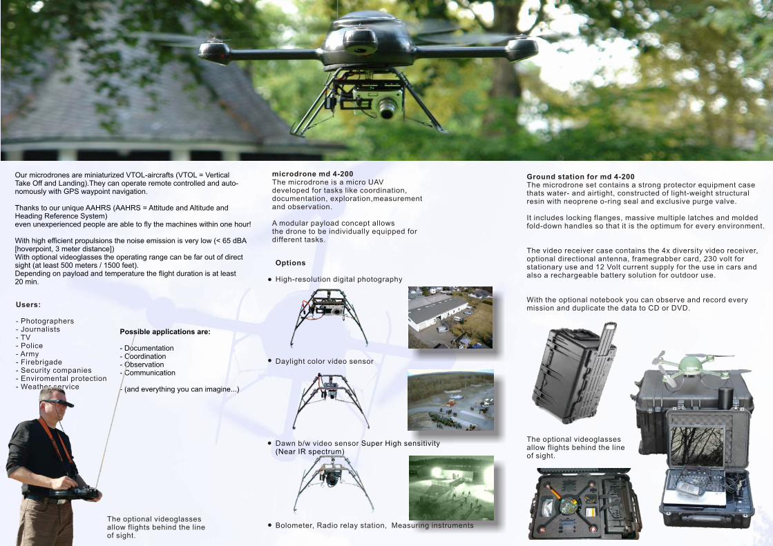
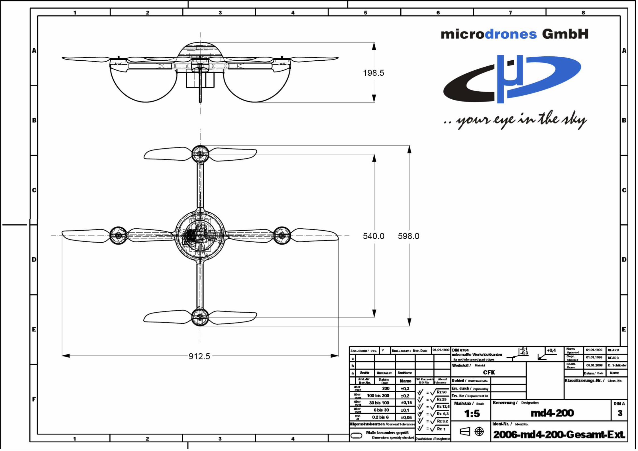
micro drone flyer md4-200
DESCRIPTION
Flyer from the new wave in New World Order technologies recently instituted by the U.K. Police http://www.microdrones.com/TRANSCRIPT


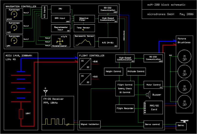
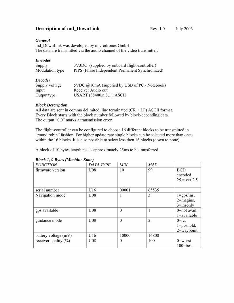
Description of md_DownLink Rev. 1.0 July 2006 General md_DownLink was developed by microdrones GmbH. The data are transmitted via the audio channel of the video transmitter. Encoder Supply 3V3DC (supplied by onboard flight-controller) Modulation type PIPS (Phase Independent Permanent Synchronized) Decoder Supply voltage 5VDC @10mA (supplied by USB of PC / Notebook) Input Receiver Audio out Output type USART (38400,n,8,1), ASCII Block Description All data are sent in comma delimited, line terminated (CR + LF) ASCII format. Every Block starts with the block number followed by block-depending data. The output “0,0” marks a transmission error. The flight-controller can be configured to choose 16 different blocks to be transmitted in “round robin” fashion. For higher update rate single blocks can be selected more than once within the 16 blocks. It is also possible to select less then 16 blocks (down to none). A block of 10 bytes length needs approximately 25ms to be transferred. Block 1, 9 Bytes (Machine State) FUNCTION DATA TYPE MIN MAX firmware version U08 10 99 BCD
encoded 25 = ver 2.5
serial number U16 00001 65535 Navigation mode U08 1 3 1=gps/ins,
2=magins, 3=insonly
gps available U08 0 1 0=not avail., 1=available
guidance mode U08 0 2 0=rc, 1=poshold, 2=waypoint
battery voltage (mV) U16 10000 16800 receiver quality (%) U08 0 100 0=worst
100=best

Block 2, 13 Bytes (RC-Values) FUNCTION DATA TYPE MIN MAX rc throttle value S08 -100 100 rc pitch value S08 -100 100 rc roll value S08 -100 100 rc yaw value S08 -100 100 rc aux1 value S08 -100 100 rc aux2 value S08 -100 100 rc s1 value S08 -100 100 rc s2 value S08 -100 100 rc s3 value S08 -100 100 rc alternate throttle S08 -100 100 rc alternate pitch S08 -100 100 rc alternate roll S08 -100 100 rc alternate yaw S08 -100 100 Block 3, 4 Bytes (Motors) FUNCTION DATA TYPE MIN MAX front motor value U08 0 255 left motor value U08 0 255 rear motor value U08 0 255 right motor value U08 0 255 Block 4, 10 Bytes (Times) FUNCTION DATA TYPE MIN MAX operating time (s) float 0 10000.0 time since
power up gps itow (ms) U32 0 604800000 GPS Time
of Week flight time (s) U16 0 65535 Block 5, 16 Bytes (GPS-Position) FUNCTION DATA TYPE MIN MAX gps pos ecef x (cm) S32 -1000000000 +1000000000 gps pos ecef y (cm) S32 -1000000000 +1000000000 gps pos ecef z (cm) S32 -1000000000 +1000000000 gps pos accuracy (m) float 0.0 999999.0 Block 6, 16 Bytes (GPS-Speed) FUNCTION DATA TYPE MIN MAX gps velo north (m/s) float -100.0 +100.0 gps velo east (m/s) float -100.0 +100.0 gps velo down (m/s) float -100.0 +100.0 gps speed accuracy (m/s) float 0.0 999999.0
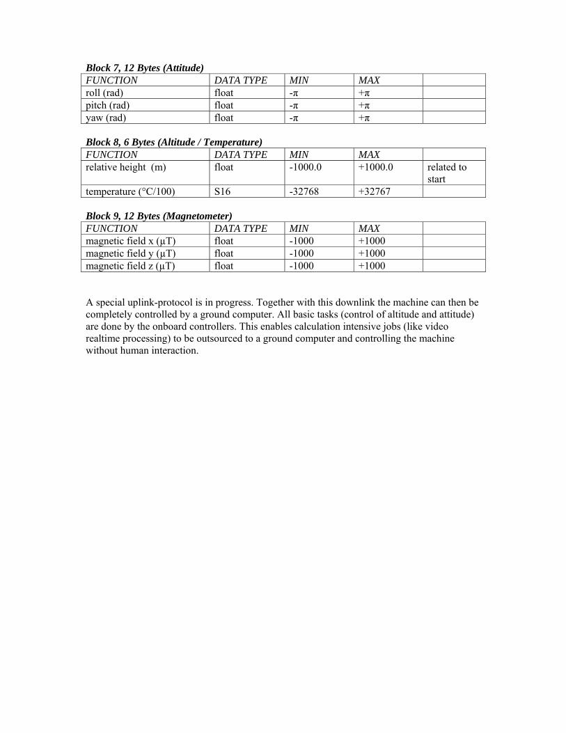
Block 7, 12 Bytes (Attitude) FUNCTION DATA TYPE MIN MAX roll (rad) float -π +π pitch (rad) float -π +π yaw (rad) float -π +π Block 8, 6 Bytes (Altitude / Temperature) FUNCTION DATA TYPE MIN MAX relative height (m) float -1000.0 +1000.0 related to
start temperature (°C/100) S16 -32768 +32767 Block 9, 12 Bytes (Magnetometer) FUNCTION DATA TYPE MIN MAX magnetic field x (µT) float -1000 +1000 magnetic field y (µT) float -1000 +1000 magnetic field z (µT) float -1000 +1000 A special uplink-protocol is in progress. Together with this downlink the machine can then be completely controlled by a ground computer. All basic tasks (control of altitude and attitude) are done by the onboard controllers. This enables calculation intensive jobs (like video realtime processing) to be outsourced to a ground computer and controlling the machine without human interaction.