micro machining of injection mold inserts for fluidic channel of polymeric biochips
TRANSCRIPT

Sensors 2007, 7, 1643-1654
sensors ISSN 1424-8220 © 2007 by MDPI
www.mdpi.org/sensors
Full Research Paper
Micro Machining of Injection Mold Inserts for Fluidic Channel of Polymeric Biochips
Woo-Chul Jung 1, Young-Moo Heo 1, Gil-Sang Yoon 1, Kwang-Ho Shin 1, Sung-Ho Chang 1, Gun-Hee Kim 2 and Myeong-Woo Cho 2,*
1 Precision Molds & Dies Team, Incheon R&D Center, KITECH, Incheon 406-840, Korea
E-mail: bogus2@ kitech.re.kr; [email protected]; [email protected]; [email protected];
2 Department of Mechanical Engineering, Inha University, Incheon 402-751, Korea
E-mail: [email protected]; [email protected]
* Author to whom correspondence should be addressed.
Received: 11 June 2007 / Accepted: 24 August 2007 / Published: 27 August 2007
Abstract: Recently, the polymeric micro-fluidic biochip, often called LOC (lab-on-a-chip),
has been focused as a cheap, rapid and simplified method to replace the existing
biochemical laboratory works. It becomes possible to form miniaturized lab functionalities
on a chip with the development of MEMS technologies. The micro-fluidic chips contain
many micro-channels for the flow of sample and reagents, mixing, and detection tasks.
Typical substrate materials for the chip are glass and polymers. Typical techniques for
micro-fluidic chip fabrication are utilizing various micro pattern forming methods, such as
wet-etching, micro-contact printing, and hot-embossing, micro injection molding, LIGA,
and micro powder blasting processes, etc. In this study, to establish the basis of the micro
pattern fabrication and mass production of polymeric micro-fluidic chips using injection
molding process, micro machining method was applied to form micro-channels on the
LOC molds. In the research, a series of machining experiments using micro end-mills were
performed to determine optimum machining conditions to improve surface roughness and
shape accuracy of designed simplified micro-channels. Obtained conditions were used to
machine required mold inserts for micro-channels using micro end-mills. Test injection
processes using machined molds and COC polymer were performed, and then the results
were investigated.
Keywords: Biochip; lab-on-a-chip; micro machining; injection molding; mold inserts.

Sensors 2007, 7
1644
1. Introduction
Recently, with the development of MEMS (micro electro-mechanical system) technologies,
conventional biotechnological analytical processes can be rapidly performed using miniaturized
biochips. Typical biochips can be categorized into two groups; micro-array and micro-fluidic chips.
The micro-array has an array of miniaturized test sites on a chip. The number of micro-arrays varies
from a hundred to a few thousand; and the typical size of the test sites ranges from 10 to 500µm.
Because the micro-fluidic chip can perform multiple tasks in a typical biochemical analysis laboratory,
such as mixing, reaction, separation, and detection, etc., it is often called as LOC (lab-on-a-chip) or
µTAS (micro total analysis system).[1,2] Advantages of the LOC are; (1) required time for analysis is
much shorter, (2) very small amount of specimen and reagent are required, (3) low cost, high analysis
accuracy, low contamination, and easy to use, etc. Thus, the micro-fluidic chips have been focused as a
leading technology in related fields.[3-6] Unlike the micro-array, the micro-fluidic chip contains many
micro-channels to connect the unit tasks for consecutive processing steps.[1] The continuous flow of
input test samples and reagents through the micro-channels can make the analytical process to be
performed on a chip by minimizing sample contamination and processing time. Typical substrate
materials for micro-fluidic chip fabrication are glasses (such as fused silica glass, etc.) or polymers
(such as PDMS (polydimethyl siloxane), PMMA (polymethyl metacrylate), COC (cyclic olefin
copolymer) etc.). The substrates for micro-fluidic chips should be biocompatible since most of they are
used for biological analysis. Besides, various material properties such as mechanical strength, porosity,
and hydrophobicity, etc., are required for real application. Fabrication procedures of such substrate
depend on the used material and complexity of the chip. Typical technique for micro-fluidic chip
fabrication is based on the soft lithography, such as wet-etching, micro-contact printing, and hot-
embossing, micro injection molding, etc.[2-5] Also, LIGA and micro powder blasting processes are
applied to form required micro-channels on the biochips.[7] Several studies were performed to
replicate microchips using metal mold masters which were prepared by CNC micro-milling processes.
[8-11] In the studies, brass [7] and aluminum masters [9-11] with micro-channels were machined to
replicate PMMA and thermosetting resin by hot embossing.
In this study, to establish the basis of the micro pattern fabrication and mass production of
polymeric micro-fluidic chips using injection molding process, micro machining method was applied
to form micro-channels on the LOC molds. As a first step, simplified micro-channels were designed
based on existing research results. Then, a series of machining experiments using micro end-mills were
performed to determine optimum machining conditions to improve better surface roughness and shape
accuracy. Obtained conditions were used to machine required mold inserts for micro-channels using
micro end-mills of 400µm diameter. Finally, test injection processes using machined molds and COC
polymer were performed, and the results were investigated. As the results, it can be observed that the
required micro-fluidic chips can be obtained using injection molding process.
2. Design of a Sample Biochip with Micro-channels
Figure 1 shows a sample of the LOC designed by the MicroSystems and BioMEMS Lab at
University of Cincinnati.[3] As can be seen in the figure, there are many micro-channels for the

Sensors 2007, 7
1645
required biochemical processes. Thus, for the experiments of this research, a simplified biochip with
micro-channels was designed based on the existing research results as illustrated in Figure 2. The
designed biochip is composed of an upper plate C and a bottom plate D (Figure 2(a)). By closing the
upper plate, square-type micro channels (width=100µm and depth=100µm) can be formed between the
plates (Figure 2(b)). As shown in the Figure 2(c), A1 and A2 are the inlet ports for the reagent and test
sample; B is the sensing port of the reaction result. The micro-channel is formed between the ports A
and B for sufficient mixing of the reagent and test sample. It is designed to have 90mm of total flow
distance and 70mm of detection length for 700nl resolution.
Multiple reagents, matrix solution inlets LIF detection point
Specific functional column
Pressure gas inlets
On-chip target
Column packing inlet
Multiple reagents, matrix solution inlets LIF detection point
Specific functional column
Pressure gas inlets
On-chip target
Column packing inlet
Inlets for different reagent solutionsSample solution inlet
Inlets for different reagent solutionsSample solution inlet
(a) Conceptual drawing. (b) Photograph.
Figure 1. A disposable lab-on-a-chip device with a specific bead packed column for MALDI-MS.[3]
(a) Biochip. (b) Cross-sectional view. (c) Top view.
Figure 2. Designed simplified micro-fluidic channels for experiments.
3. Machining Experiments Using Micro End-mills
3.1. Experimental Setup
Experimental setup for the micro-channel machining is shown in Figure 3. Figure 3(a) shows the 3-
axis micro stage; resolution of each linear carriage is 0.1µm, and maximum rotational speed of main
spindle is 100,000rpm. Generally, the micro end-milling process requires much higher specific energy
than the traditional cutting processes since the tool diameter is very small. In many cases, such high
specific cutting energy consumption causes higher cutting heat, shorter tool life and serious burr
formation, etc. Thus, an oil mist supplier and a suction unit are attached to the system for more

Sensors 2007, 7
1646
effective machining of micro-channel with higher accuracy and better surface roughness. One of the
used micro end-mill is shown in Figure 3(b); its diameter=200µm, length of cutter=400µm and helix
angle=15degree. Generally, micro end-mills are made with WC (tungsten carbide), and have lower
aspect ratio than traditional end-mill to compensate its low rigidity. Also, NAK80, which is a
precipitation or age-hardened mold steel with a uniform through hardness of approximately 40 HRC,
was chosen as the test workpiece material.
(a) 3-axis micro machining stage. (b) Micro end-mill (diameter=200µm).
Figure 3. Experimental setup for the micro machining of mold inserts.
3.2. Experiments for Surface Roughness Improvement
Surface roughness of the machined micro-channel is an important factor to determine the liquid fluidity in the channel. Since the conventional finishing processes, such as polishing, lapping, etc., are almost impossible for micro-channel fabrication, it is very important to decide optimum machining conditions based on the required experimental results. Thus, as a first step of this research, the relationship between the machining condition and surface roughness was investigated through a series of experiments.
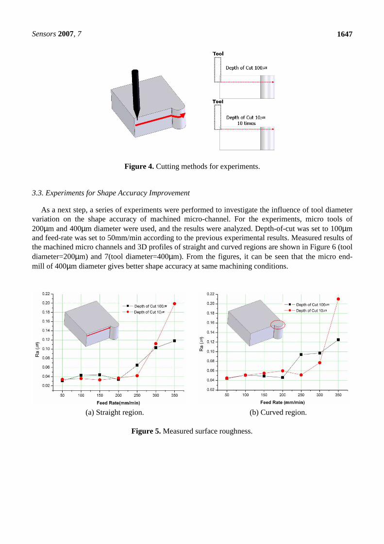
Since the micro-channels for the biochips have straight and curved regions, a test specimen was designed to have both regions with same curvature as shown in Figure 4. The specimen was cut by two methods at constant spindle speed of 17,000rpm and by changing the feed-rates as follows; (a) 1 pass cutting, depth-of-cut was 100µm, (b) 10 times of step cutting, depth-of-cut for each step was 10µm. Measured results of the surface roughness are shown in Figure 5(a) and (b) for straight and curved region, respectively. The best results were observed when the depth-of-cut was 100µm and feed-rate was 50mm/min for both of the straight (Ra=31nm) and curved (Ra=44nm) regions.
Sensors 2007, 7
1647
Figure 4. Cutting methods for experiments.
3.3. Experiments for Shape Accuracy Improvement
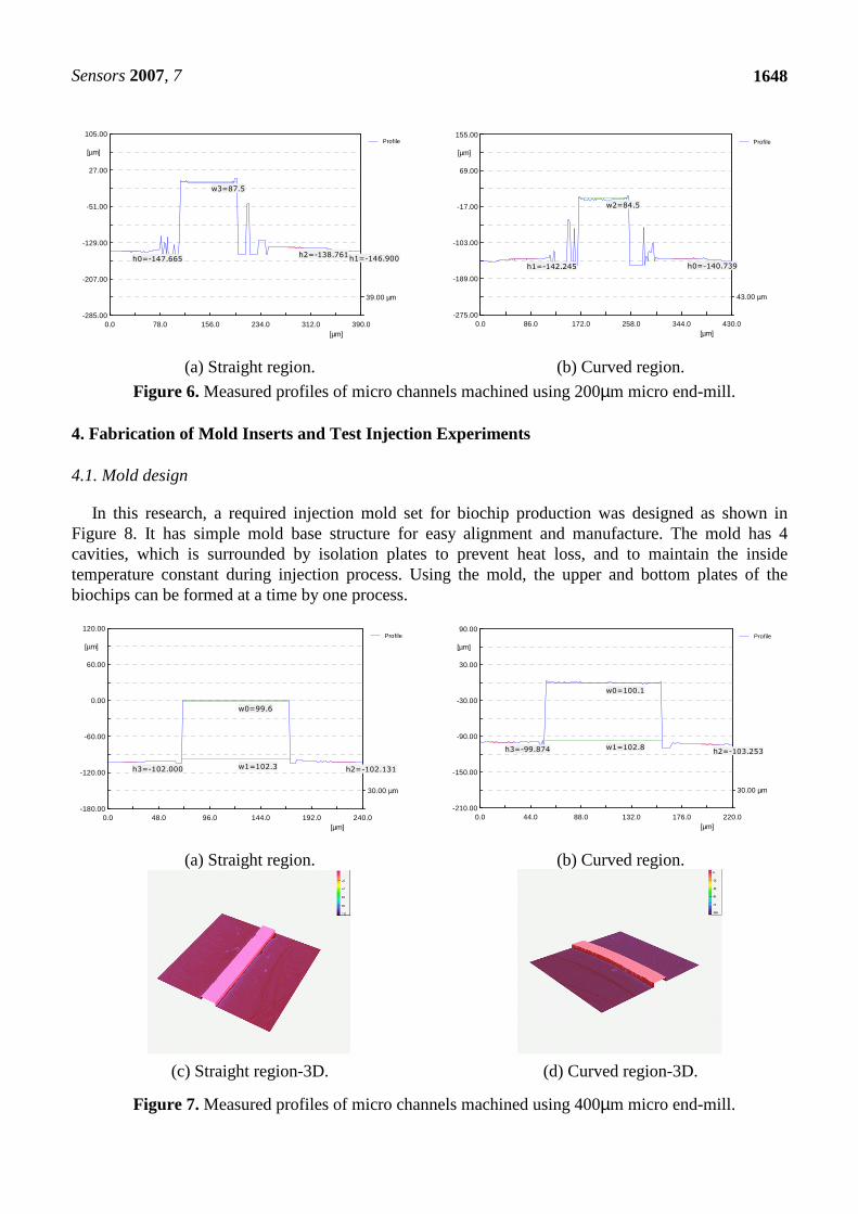
As a next step, a series of experiments were performed to investigate the influence of tool diameter variation on the shape accuracy of machined micro-channel. For the experiments, micro tools of 200µm and 400µm diameter were used, and the results were analyzed. Depth-of-cut was set to 100µm and feed-rate was set to 50mm/min according to the previous experimental results. Measured results of the machined micro channels and 3D profiles of straight and curved regions are shown in Figure 6 (tool diameter=200µm) and 7(tool diameter=400µm). From the figures, it can be seen that the micro end-mill of 400µm diameter gives better shape accuracy at same machining conditions.
(a) Straight region. (b) Curved region.
Figure 5. Measured surface roughness.
Sensors 2007, 7
1648
0.0 78.0 156.0 234.0 312.0 390.0[µm]
39.00 µm
-285.00
-207.00
-129.00
-51.00
27.00
105.00
[µm]
Profile
h0=-147.665 h1=-146.900h2=-138.761
w3=87.5
0.0 86.0 172.0 258.0 344.0 430.0[µm]
43.00 µm
-275.00
-189.00
-103.00
-17.00
69.00
155.00
[µm]
Profile
h0=-140.739h1=-142.245
w2=84.5
(a) Straight region. (b) Curved region.
Figure 6. Measured profiles of micro channels machined using 200µm micro end-mill.
4. Fabrication of Mold Inserts and Test Injection Experiments
4.1. Mold design
In this research, a required injection mold set for biochip production was designed as shown in Figure 8. It has simple mold base structure for easy alignment and manufacture. The mold has 4 cavities, which is surrounded by isolation plates to prevent heat loss, and to maintain the inside temperature constant during injection process. Using the mold, the upper and bottom plates of the biochips can be formed at a time by one process.
0.0 48.0 96.0 144.0 192.0 240.0[µm]
30.00 µm
-180.00
-120.00
-60.00
0.00
60.00
120.00
[µm]
Profile
w0=99.6
w1=102.3 h2=-102.131h3=-102.000
0.0 44.0 88.0 132.0 176.0 220.0[µm]
30.00 µm
-210.00
-150.00
-90.00
-30.00
30.00
90.00
[µm]
Profile
w0=100.1
w1=102.8h2=-103.253h3=-99.874
(a) Straight region. (b) Curved region.
(c) Straight region-3D. (d) Curved region-3D.
Figure 7. Measured profiles of micro channels machined using 400µm micro end-mill.

Sensors 2007, 7
1649
(a) Bottom part. (b) Upper part.
Figure 8. Designed injection mold set.
Table 1. Applied conditions for core machining.
Feed-rate 50mm/min RPM 17,000
Depth-of-cut 100µm Tool Union 400µm
Side depth-of-cut 10µm Machine DMU 100T
4.2. Mold Fabrication for Biochips
Based on the previous experimental results, the optimum conditions for core machining to form micro channel were determined as shown in Table 1. SKD11 was used for inject pin and guide bush manufacture; and NAK80 was used for mold cavity and cores for micro channel forming. Figure 9(a) shows the mirror-finished bottom plate core for micro-channel machining. Figure 9(b) and (c) show the machined core, and (d) shows the assembled mold set for the test injection experiments. As shown in figure, 4 cavities are assembled in a mold set.
(a) Bottom plate core after mirror-finishing. (b) Machined core by micro end-milling.
(c) Micro-fluidic channel on the core. (d) Assembled mold set for test injection.
Figure 9. Manufactured core and injection mold.

Sensors 2007, 7
1650
4.3. Injection Molding Characteristics of COC
The materials used for test injection process were COC (cyclic olefin copolymer), which have good
material properties, such as high transparency, low double refraction, low absorptive property, and
biocompatibility, etc. To investigate the injection characteristics using the developed molds, two types
of COC resins (Topas 5013S-04 and 8007S-04) were used. Thermal properties of COC and their
viscosity characteristics are shown in Table 2 and Figure 10.
Table 2. Thermal properties of COC
COC 5013S-04 8007S-04
Melt temperature 260°C 230°C
Glass transition temperature 136°C 80°C
Viscosity index (MPI data) VI(260)0058 VI(260)0091
(a) Topas5013S-04 (b) Topas8007S-04
Figure 10. Viscosity characteristics of COC resins.
Table 3. Injection conditions for test injection.
No.
Polymer Temp.(°C) Injection
Pressure
(kgf/㎠)
Flow
Rate
(㎤/sec)
No.
Polymer Temp.(°C) Injection
Pressure
(kgf/㎠)
Flow
Rate
(㎤/sec) 5013S-04 8007S-04 5013S-04 8007S-04
1
270 250
1263
23 15
280 260
1768 41.4
2 33.2 16
2273
23
3 41.4 17 33.2
4
1768
23 18 41.4
5 33.2 19
290 270
1263
23
6 41.4 20 33.2
7
2273
23 21 41.4
8 33.2 22
1768
23
9 41.4 23 33.2
10
280 260
1263
23 24 41.4
11 33.2 25
2273
23
12 41.4 26 33.2
13 1768
23 27 41.4
14 33.2

Sensors 2007, 7
1651
To investigate the filling characteristics of the polymers into the micro channels in injection
processes, a micro rib feature was designed and machined as shown in Figure 11. Applied injection
conditions are listed in Table 3, and the results are shown in Figure 12 and 13. Figure 14 and 15 show
the measured results of the micro rib filling experiments.
WWWW
HHHHAAAABBBB
CCCCDDDD
W=50W=50W=50W=50㎛㎛㎛㎛
H=500H=500H=500H=500㎛㎛㎛㎛
W=100W=100W=100W=100㎛㎛㎛㎛
H=1000H=1000H=1000H=1000㎛㎛㎛㎛
W=150W=150W=150W=150㎛㎛㎛㎛
H=1500H=1500H=1500H=1500㎛㎛㎛㎛
W=200W=200W=200W=200㎛㎛㎛㎛
H=2000H=2000H=2000H=2000㎛㎛㎛㎛ Figure 11. Micro rib feature for test injection experiments.
(a) W=50µm (b) W=100µm (c) W=150µm (d) W=200µm
Figure 12. Test injection results using Topas5013S-04.
(a) W=50µm (b) W=100µm (c) W=150µm (d) W=200µm
Figure 13. Test injection results using Topas8007S-04.
(a) W=50µm (b) W=100, 150, 200µm
Figure 14. Measured results of the filling experiments for Topas5013S-04.

Sensors 2007, 7
1652
(a) W=50µm (b) W=100, 150, 200µm
Figure 15. Measured results of the filling experiment for Topas8007S-04.
From the figures, it can be observed that Topas8007S-04 has better micro filling characteristics,
especially when W=50µm, than Topas5013S-04.
4.4. Test Injection of Sample Bipchips
Test injection process using the fabricated mold set is shown in Figure 16(a), and the injected
samples of biochip are shown in Figure 16(b). From the figures, it can be seen that the micro-channels
are formed on the polymer plates successfully.
(a) Mold set for test injection. (b) Test injected biochips.
Figure 16. Test injection process and samples of polymeric LOC.
5. Conclusions
In this study, injection mold inserts for micro-channel forming on the biochip were manufactured
using micro end-mills. Micro rib filling experiments were performed to evaluate the characteristics of
polymers. And, test injection process was performed using the fabricated inserts and mold set. From
the results of this study, it can be shown that the method can be applied for the mass production of
biochips. The results of this study can be summarized as follows:
(1) In micro end-milling process, the best surface roughness could be obtained at depth-of-cut was
100µm and feed-rate was 50m/min. Under the condition, surface roughness of Ra=31nm was obtained
for the straight regions, and Ra=44nm for curved regions.

Sensors 2007, 7
1653
(2) When tool diameter was 400µm, better shape accuracy of the micro-channel could be obtained than
the 200µm diameter tool.
(3) The mold inserts for micro-channel forming was machined based on the experimental data.
(4) In micro rib filling experiments, Topas8007S-04 showed better filling characteristics than
Topas5013S-04.
(5) Test injection process was performed successfully. Thus, it can be shown that the applied method
can be a way for the mass production of biochips.
(6) To form more precise micro channel patterns using injection molding process for biochip
production, more extended studied such as tool deflection compensation, micro-fluidics analysis for the
given polymers, etc. are needed as the future works.
Acknowledgements
This research was supported by 2010 Renovation Plan of Fundamental Manufacturing Technology
(Strategic Project) from Korea Institute of Industrial Technology.
References and Notes
1. Song, S.; Lee, K.Y. Polymers for Microfluidic Chips. Macromolecular Research 2006, 14, 121-
128.
2. Reyes, D. R.; Iossifidis, D.; Auroux, P.A.; Manz, A. Micro Total Analysis System. 1. Introduction,
Theory and Technology. Analytical Chemistry 2002, 74, 2623-2636.
3. Ahn, C.H. Appication of Micro Molding Technology to BioMEMS Components and Systems
2006, University of Cincinnati, Internal technical report to KITECH, Korea,
4. Blattert C. Separation of Blood Cells and Plasma in Microchannel Bend Structures. Proceedings
of µTAS 2004, 1, 483–485.
5. Michael, J. H. DNA Micro Array Technology: Devices, Systems and Applications. Annual Review
of Biomedical Engineering 2002, 4, 129-153.
6. Kurian, K. M.; Watson, C. J.; Wylie, A. H. DNA Chip Technology. Journal of Pathology 1999,
187, 267-271.
7. Jakeway, S. C.; de Mello, A. J.; Russell, E. L. Miniaturized Total Analysis Systems for Biological
Analysis. Analytical Chemistry 2000, 66, 525-539.
8. Hupert, M.L.; Guy, W.J.; Llopis, S.D.; Shadpour, H.; Rani, S.; Nikitopoulos, D.E.; Soper, S.A.
Evaluation of micromilled metal mold masters for the replication of microchip electrophoresis
devices. Microfluidics and Nanofluidics 2007, 3, 1-11.
9. Mecomber, J.S.; Stalcup, A.M.; Hurd, D.; Halsall, H.B.; Heineman, W.R.; Seliskar, C.J.;
Wehmeyer, K.R.; Limbach, P.A., Analytical Performance of Polymer-Based Microfluidic Devices
Fabricated By Computer Numerical Controlled Machining. Analytical Chemistry 2006, 78, 936-
941.
10. Mecomber, J.S.; Hurd, D.; Limbach, P.A., Enhanced machining of micro-scale features in
microchip molding masters by CNC milling. Int. J. of Machine Tools and Manufacture 2005, 45,
1542-1550.

Sensors 2007, 7
1654
11. Zhao, D.S.; Roy, B.; McCormick, M.T.; Kuhr, W.G.; Brazill, S.A. Rapid fabrication of a
poly(dimethylsiloxane) microfluidic capillary gel electrophoresis system utilizing high precision
machining, Lab on a Chip 2003, 3, 93-99.
© 2007 by MDPI (http://www.mdpi.org). Reproduction is permitted for noncommercial purposes.