micro optics in applied spectroscopy - … · comes from the fact that a reliable sensor needs to...
TRANSCRIPT

MICRO OPTICS IN APPLIED SPECTROSCOPY
Matthieu Lacolle1, Ib-Rune Johansen1, Thor Bakke1, Håkon Sagberg2
1Microsystems and Nanotechnology , SINTEF ICT, Oslo, Norway 2GasSecure, Oslo, Norway
Abstract — We present the design and implemen-
tation of different types of specialized spectrometers based on optical diffractive filters and that are well suited for gas sensing. The optical filter is the central component in the sensor and integrates into a single surface hologram the functions of lenses, beam-splitters and optical filters. It is also possible to switch between several filter transmissions without the need for complicated or precise mechanical control. Thanks to this design, the sensors do not need frequent recalibration or maintenance. In addition, the simplicity of the system makes it well suited for a wide range of applications either the requirements are a low production cost or robust-ness to harsh industrial environment. In the follow-ing we present three types of optical diffractive filters and give examples where the devices have been industrialized, mainly for gas spectroscopy.
Keywords : Diffractive optics, wavelength filtering
devices I - Introduction Stable and robust gas sensors with a minimum need
for maintenance and recalibration are needed for online continuous measurements. Gas sensors based on Infra Red (IR) spectrometry are considered as the most reliable gas sensors and are often the preferred choice for demanding applications like hydrocarbon gas leak-age detection in the petroleum industry. A challenge comes from the fact that a reliable sensor needs to be able to compensate for changes in detector and source response, as well as changes in the optical measurement path.
A gas sensor can be implemented with a spectrome-ter measuring the spectral absorption of a gas. There exist different types of spectrometers that have been miniaturized and can be produced at low cost. An example is grating spectrometers with detector arrays [1]. Unfortunately, detector arrays will, especially when sensitive to NIR or IR wavelengths, suffer from drift in the pixel response. In practice, such a spectrometer would require a calibration procedure prior to each measurement. An alternative is to use a single source and a single detector and scan the grating. But this requires precise mechanical control of the grating position, which is costly and not well suited to industrial environments subject to vibrations and where moving parts are prohibited.
A number of clever solutions have been developed during the last three decades to avoid the use of moving parts such as a scanning grating and to compensate for
drift in the system. These solutions involve two sources, two detectors, two filters, two beam splitters and several lenses, forming a doubly compensated system. The drawback is a relatively high cost due to the number of components and a low optical efficiency due to the use of several beam splitters.
New ideas in diffractive design have made possible the implementation of optical sensors with all the necessary functionalities, based on a low cost diffractive optical filter, a single source and in most cases a single detector. There is no requirement for frequent recalibra-tion of the system or a complicated scanning mecha-nism. This is achieved by integrating the functions of lenses, beam-splitters and optical filters into a single surface hologram or diffractive optical element, which results in a simple spectrometer arrangement, shown in Figure 1. In the following, we will present three differ-ent types of diffractive optical sensors for use in CO2, CO and hydrocarbon detection. The three designs differ mainly by the way they switch between different filter transmissions.
Figure 1: An optical sensor with a diffractive element that integrates several optical functions. Here measuring transmis-sion through a gas.
II – The HoloChip technology The HoloChip design utilizes both the dispersing
and the focusing abilities of Fresnel zone plates. The standard grating and collimating optics of a scanning spectrometer are replaced by a dispersing and focusing element [2]. An inherent scanning reference is obtained by splitting and focusing dispersed light at e.g. four points, as illustrated in Figure 2. Each of these four points will now contain only the preselected wavelength band and these wavelength bands can be scanned over the detector by mechanically tilting the HoloChip element. The spectral content of light reaching the detector as the HoloChip is scanned can been seen in Figure 3.

Figure 2: The HoloChip is designed to focus, disperse and split the light, here at four locations in the detection area.
Figure 3: Spectral content of the light reaching the detector as the HoloChip is scanned.
The scanning mechanism does not need to be accu-rate, as the signal detected on the detector is not contin-uous but consists of several tops corresponding to the different wavelength bands programmed in the Holo-Chip. A simple way to implement a scanning mecha-nism is to mount the HoloChip onto a steel spring and driving the spring back and forth with a small magnet and a coil, as shown in Figure 4. This simple design makes possible the implementation of low cost and robust dedicated spectrometers.
Figure 4: The scanning mechanism of the HoloChip.
Depending on the application and production volume, several fabrication methods for the HoloChip can be used. For high volume, a master can be produce either by electroplating of a polymer profile created by elec-tron beam lithography or alternatively by micromachin-ing of a silicon wafer. Replica of the master can then be fabricated by injection moulding with equipment similar
to those used for the production of standard compact discs. This way a HoloChip can be produce at a price below 1€. An example is shown in Figure 5. For smaller scale production it is possible to etch the HoloChip directly on silicon wafers with standard photolithogra-phy and dry ion etching. A four level HoloChip etched in silicon is shown in Figure 6. This fabrication method also offer the advantage of resulting in a sensor that is extra robust for temperature variation (silicon thermal expansion coefficient is low). Instead of mounting the HoloChip with a separate spring, the spring for the scanning mechanism can also be produced at the same time as the HoloChip by injection moulding or silicon micromachining.
Figure 5: A HoloChip fabricated by injection moulding and mounted on a steel spring.
Figure 6: Surface profile of a HoloChip etched in silicon.
In one application, we have implemented a sensor for carbon dioxide (CO2) measurement. CO2 absorbs in the spectral region around 4.3 µm. Our sensor uses a single optical path from the source, via the scanning HoloChip, and onto a single detector. By measuring on the absorp-tion wavelength, as well as on both sides of this, any drift in the source, detector and path can be compen-sated for. CO2 sensors for ventilation control (see Figure 7) have been industrialized by OptoSense AS and they now guarantee a CO2 accuracy of better than 30 ppm in the 600-1200 ppm concentration range as well as a long term drift of less than 4 ppm per year. In another appli-cation that does not imply gas sensing, TOMRA Sys-tems has industrialized the HoloChip technology for use in plastic sorting and recycling, using a different design with five different wavelength bands in NIR. A recy-

cling centre for automated sorting of plastic packages is shown in Figure 8.
Figure 7: A sensor based on the HoloChip for CO2 measure-ment in ventilation control systems.
Figure 8: A TOMRA automated recycling centre that uses the HoloChip for the sorting of plastic packages.
III - Two-state micromechanical diffractive filter A two-state optical micromechanical filter for gas
sensing has been developed [3,4]. This filter includes the functionalities of focusing, dispersing and band-pass filtering into a single diffractive element, which can be seen in Figure 9. These abilities are shared with the HoloChip. But at the difference of the HoloChip, no scanning mechanism is necessary at all, this function being integrated into the electrostatically actuated silicon micromechanical structure fabricated with the hologram at the chip level. This makes the device well suited for very demanding applications where moving parts are completely prohibited.
Figure 9: A two-state micro mechanical diffractive filter in its package.
The two-state micromechanical filter consists of an off-axis part of a diffractive lens. The diffraction pattern is etched at the surface of silicon beams. Every second beam is attached to a frame suspended by springs, and that can be moved down by a quarter of a wavelength by electrostatic actuation, as illustrated in Figure 10. The total size of the filter is 5 x 5 mm, consisting of a matrix of 8 x 8 frames of the types shown in Figure 10.
Figure 10: Wight Light Interferometry picture of a microme-chanical frame that has been moved down. The diffraction pattern on top of the beams is not resolved in this picture.
When the filter is not actuated, a single wavelength band is generated at the absorption lines of the relevant gas. Actuating the device gives rise to a sideband on each side of the target wavelength, as shown in Figure 11. By alternating the control voltage, the filter is alternating between a target filter (solid line) and a split reference filter (dashed line).
Figure 11: The filter is alternating between a target filter (solid line) and a split reference filter (dashed line).
The filter can be actuated by 20 V, and can be oper-ated at several kHz. This is a great advantage compared to other sensors, since the 1/f-noise can be totally eliminated by high frequency operation. In one configu-ration for the measurement of pentane (violet curve in Figure 11), the filter was operated at 800 Hz, with a 1 mm PbSe detector, a 900 K source and a 1 meter optical path length , giving a detection limit of 0.1 ppm. The sensor accuracy was however limited by long term drift and temperature drift to around 10 ppm.
This two-state micromechanical filter is being used in a sensor monitoring hydrocarbons in a car carrier ship. In this application, hydrocarbons produced when loading and unloading the ship, as well as outgassing from material or potential leakage might pose a health
or safety issusensor is comsection IV ofin Figure 12measured gaventilation of
The two-trialized by wireless infrapictured in Fthe low powtime that havthis type of s
Figure 12: A cinstallation on
Figure 13: A wGasSecure AS
IV - Higtection
Carbon m
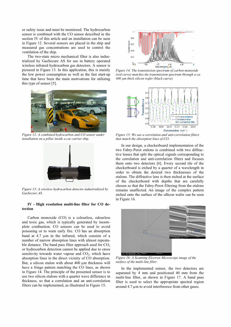
and toxic gaplete combupoisoning orband at 4.7 number of nable distance. or hydrocarbsensitivity toabsorption liBut, a siliconhave a fringein Figure 14.use two silicothickness, sofilters can be
ue and must bmbined with thf this article a. Several sensas concentratif the ship. -state micro mGasSecure Aared hydrocar
Figure 13. In twer consumpti
ve been the msensor [5].
combined hydron a pillar inside
wireless hydrocS.
gh resolution
monoxide (COas, which is tustion. CO ser to warn earlm in the i
arrow absorptThe band pas
bon detection cowards water nes in the dirn etalon withe pattern mat. The principlon etalons wito that a corree implemented
e monitored. he CO sensorand an installasors are placeions are used
mechanical filtAS for use in rbon gas detecthis applicatioon as well asmain motivati
ocarbon and COe a car carrier s
carbon detector
multi-line fi
O) is a coloutypically geneensors can bely fire. CO hinfrared, whiction lines withss filter approacannot be appvapour and C
rect vicinity oh about 400 ching the COle of the preseth a quarter w
elation and and, as illustrated
The hydrocarbr described in ation can be sd in the ship d to control
ter is also indbattery opera
ctors. A sensoon, this is mais the fast startions for utiliz
O sensor under ship.
r industrialized
ilter for CO
urless, odourlerated by incoe used to av
has an absorptch consists oh almost repeaach used for Cplied due to crCO2, which hf CO absorptim thickness w
O lines, as shoented sensor i
wave differencn anti-correlatd in Figure 15
bon the
seen and the
dus-ated or is inly t-up zing
r
by
de-
less om-void tion of a ata-CO2 ross
have ion. will own s to e in tion
5.
Figure (red cu400 µm
Figure that ma
In two Ftive lethe cothem ocheckeorder etalonof thechosenremainetchedin Figu
Figure surface
In separamulti-filter iaround
14: The transmurve) matches thm thick silicon w
15: We use a catch the absorp
our design, a abry-Perot eta
enses that splitorrelation andonto two deteerboard is etcto obtain th
s. The diffrace checkerboan so that the Fns unaffectedd onto the surfure 16.
16: A Scanninge of the multi-lin
the implemeated by 4 mmline filter, asis used to sed 4.7 m to av
mission spectrumhe transmissionwafer (black cur
correlation and tion lines of CO
checkerboardalons is combt the optical si
d anti-correlatiectors [6]. Evhed by a quar
he desired twtive lens is the
ard with depFabry-Perot fil. An image oface of the sil
g Electron Micrne filter.
ented sensor, m and positio
shown in Fielect the apprvoid interferen
m of carbon mon spectrum throrve).
d anti-correlatioO.
d implementatbined with twignals corresption filters anvery second tarter of a wavwo thicknesseen etched at th
pths that are ltering from tof the complelicon wafer ca
roscope image
the two detoned 40 mm igure 17. A bropriate spectnce from othe
onoxide ugh a ca.
on filters
tion of the wo diffrac-ponding to nd focuses tile of the
velength in es of the he surface
carefully the etalons ex pattern an be seen
of the
ectors are from the
band pass ral region r gases.

Figure 17: A checkerboard of combined Fabry-Perot and diffractive lens focuses light filtered by the correlation and anti-correlation filters onto two detectors.
It could have been possible to use a single detector and a scanning mechanism to shift between the correla-tion and anti-correlation filters, similarly to the Holo-Chip described in section II. But in our application moving parts were prohibited. Therefore, a method to compensate for the drift between the two detectors had to be developed: The multi-line filter needs to be tem-perature stabilized to force the correlation lines to overlap with the CO lines, due to the thermo optical effect in silicon that makes the optical cavity length change with temperature. The periodic filter transmis-sion generated by the multi-line filter can be tuned one period by changing the temperature around 25 C. By tuning the temperature around 12.5 C, the correlation and the anti correlation lines shift from one to the other detector. This can be used to compensate for long term drift caused by change in detector response over time.
The multi-line filter has been industrialized for CO detection on board car carrier ship. 8 sensors with 1 meter optical path length have been tested for several months and show detection limits better than 10 ppm and little or no long term drift. The CO sensors are combined with hydrocarbon detectors based on the two-state micromechanical filter described in section III, and an installation can be seen in Figure 12.
V – Conclusion We have developed three different types of diffrac-
tive filters that combine the optical functions of focus-ing lenses, beam splitters and spectral filters onto the same surface hologram.
The HoloChip is a surface hologram performing a filtering at several programmed wavelength bands. The filter switches between the different wavelength bands by scanning the HoloChip, but no accurate position control of the HoloChip is necessary. The simplicity of the system made possible the fabrication of low cost sensors for CO2 monitoring or for plastic sorting.
In the two state micromechanical filter we have re-placed the scanning mechanism by an electrostatic actuation of silicon structures microfabricated at the same time as the surface hologram. This makes a very robust system without moving parts that is well suited for gas measurement in harsh industrial environment. The filter has been industrialized for hydrocarbon detection.
Finally, a multi-line filter was fabricated for the de-tection of CO. Two filter transmissions matching the CO absorption lines are implemented by combining the Fabry-Perot effect in a silicon etalon and a diffractive lens for beam splitting and focusing of the light. The filter has no moving parts and two detectors are used. The drift is compensated by controlling the temperature of the silicon filter. The filter has been industrialized to monitor CO aboard car carrier ships.
Acknowledgement This work was partly funded by ESA under the ES-
TEC contract number 20684/07/NL/PA, the Research Council of Norway and Innovation Norway. The au-thors would like to thank the staff of the SINTEF MiNaLab for substantial support in the fabrication and testing of these devices.
References [1] http://sales.hamamatsu.com/en/products/solid-state-
division/mini-spectrometers.php [2] O. Løvhaugen, I. R. Johansen, K. A. H. Bakke, S.
Nicolas, Journal of Modern Optics, Vol. 51, No.14, pp. 2203-2222, 2004.
[3] T. Bakke, H. Sagberg, J. O. Grepstad, M. Lacolle, A.
K. Herbjørnrød, G. U. Jensen, and I. R. Johansen, Optical MEMS and Nanophotonics, 2009 IEEE/LEOS, Florida, pp. 61-62, 2009.
[4] http://www.esa.int/SPECIALS/Technology/¨ SEMWFPIK97G_0.html [5] H. Sagberg, B. Fismen, N. Aakvaag, L. Borgen, P.
Nordbryhn, K. Sandven, J. Tschudi, K. A. Bakke and I.R. Johansen, 2012 OSA Optics & Photonics Congress, Monterey, California, 2012.
[6] H. Sagberg, I. R. Johansen, H. Rogne, and O.
Løvhaugen, EOS Topical Meeting on Diffractive Optics 2005, Warsaw, pp. 82-83, 2005.