microcontroller based speedo meter cum odometer
TRANSCRIPT
1 INTRODUCTION
[1] It is an digital speedometer-odometer which can be installed with a bike
[2] Digital speedometer are found only in luxury cars and high-end motor bikes
[3] The circuit uses an AT89C2051 Microcontroller a 162 LCD display4N35
optocoupler24C02 EPROM
[4] It is better alternative to the mechanical speedometer amp even beginner with minskill
level
2 WHAT IS MICROCONTROLLER
it is a small computer on a single integrated circuit containing a processor core memory
and programmable inputoutput peripherals program memory in the form of ferroelectric
ram nor flash or otp romis also often included on chip as well as a typically small amount
of ram microcontrollers are designed for embedded applications in contrast to
the microprocessors used in personal computers or other general purpose applications
microcontrollers are used in automatically controlled products and devices such as
automobile engine control systems implantable medical devices remote controls office
machines appliances power tools toys and other embedded systems by reducing the size and
cost compared to a design that uses a separate microprocessor memory and inputoutput
devices microcontrollers make it economical to digitally control even more devices and
processes mixed signal microcontrollers are common integrating analog components needed to
control non-digital electronic systems
[1]
3 DESCRIPTION-
31 Microcontroller Basics-
Any electric appliance that stores measures displays information or calculates comprise
of a microcontroller chip inside it The basic structure of a microcontroller comprise of-
311 CPU ndash
Microcontrollers brain is named as CPU CPU is the device which is employed to fetch
data decode it and at the end complete the assigned task successfully With the help of CPU all
the components of microcontroller is connected into a single system Instruction fetched by the
programmable memory is decoded by the CPU
312 Memory ndash
In a microcontroller memory chip works same as microprocessor Memory chip stores
all programs amp data Microcontrollers are built with certain amount of ROM or RAM (EPROM
EEPROM etc) or flash memory for the storage of program source codes
313 Inputoutput ports ndash
IO ports are basically employed to interface or drive different appliances such as-
printers LCDrsquos LEDrsquos etc
[2]
314 Serial Ports ndash
These ports give serial interfaces amid microcontroller amp various other peripherals such
as parallel port
315 Timers ndash
A microcontroller may be in-built with one or more timer or counters The timers amp
counters control all counting amp timing operations within a microcontroller Timers are employed
to count external pulses The main operations performed by timersrsquo are- pulse generations clock
functions frequency measuring modulations making oscillations etc
3151 ADC (Analog to digital converter) ndash
ADC is employed to convert analog signals to digital ones The input signals need to be
analog for ADC The digital signal production can be employed for different digital applications
(such as- measurement gadgets)
3152 DAC (digital to analog converter) ndash
This converter executes opposite functions that ADC perform This device is generally
employed to supervise analog appliances like- DC motors etc
3153 Interpret Control-
This controller is employed for giving delayed control for a working program The interpret can
be internal or external
[3]
3154 Special Functioning Block ndash
Some special microcontrollers manufactured for special appliances like- space systems
robots etc comprise of this special function block This special block has additional ports so as
to carry out some special operations
32 Microcontroller Applications
Microcontrollers are intended for embedded devices in comparison to the micro-
processors which are used in PCs or other all-purpose devices Microcontrollers are employed in
automatically managed inventions and appliances like- power tools implantable medical
devices automobile engine control systems office machines remote controls appliances toys
and many more embedded systems By dipping the size and expenditure in comparison to a
design that make use of a different micro-processor IO devices and memory micro-controllers
formulate it inexpensive to digitally control more amp more appliances and operations Mixed
signal micro-controllers are general putting together analog constituents required controlling
non-digital electronic structures
33 Application of Microcontroller in Day to Day Life Devices
Light sensing amp controlling devices
Temperature sensing and controlling devices
Fire detection amp safety devices
Industrial instrumentation devices
Process control devices
[4]
34 Application of Microcontroller in Industrial Control Devices
Industrial instrumentation devices
Process control devices
35 Application of Microcontroller in Metering amp Measurement Devices
Volt Meter
Measuring revolving objects
Current meter
Hand-held metering systems
4 What Is speedometer
speedometer or a speed meter is a gauge that measures and displays the
instantaneous speed of a vehicle now universally fitted tomotor vehicles they started to be
available as options in the 1900s and as standard equipment from about 1910
onwards[1]
speedometers for other vehicles have specific names and use other means of sensing
speed for a boat this is a pit log for an aircraft this is an airspeed indicator
5 What Is odometer or odograph
it is an instrument that indicates distance traveled by a vehicle such as a bicycle or
automobile the device may be electronic mechanical or a combination of the two the word
derives from the greek words hodoacutes (path or gateway) andmeacutetron (measure) in countries
where imperial units or us customary units are used it is sometimes called
a mileometer or milometer or colloquially a tripometer
[5]
6 COMPONENTS
61 Semiconductors-
IC1 - 7805 5V regulator
IC2 - AT89C2051 microcontroller
IC3 - 4N35 optocoupler
IC4 - 24C02 EEPROM
D1 - 1N4007 rectifier diode
LED1 - 5mm light-emitting diode
62 Resistors (all frac14-watt plusmn5 carbon)
RESISTORS RATING
R1 82-kilo-ohm
R2-R6 10-kilo-ohm
R7 330-ohm
R8 1-kilo-ohm
R9 47-ohm
VR1 47-kilo-ohm
[6]
63 preset Capacitors-
CAPACITOR RATING
C1 1000microF 25V electrolytic
C2 100microF 16V electrolytic
C3 01microF ceramic
C4 C5 33pF ceramic
C6 10microF 16V
TABLE 2-CAPACITOR RATING
64 electrolytic Miscellaneous-
CON1 - 2-pin SIP male connector
S1 S2 - SPST lsquoonrsquolsquooffrsquo switch
S3 - Reed switch
LCD1 - 16x2 EL1602 LCD module
XTAL1 - 12MHz crystal
[7]
Fig 1-SPEEDOMETER CUM ODOMETER
7 CIRCUIT DESCRIPTION
The circuit of the microcontroller-based digital speedometer-cum-odometer is shown in
Fig 1 The functions of various components used in the circuit are described below
71 Microcontroller-
A 20 -pin AT89C2051 microcontroller from Atmel is used here because of its low pin
count affordability and compatibility with CISC-based 8051 family All the available pins of the
microcontroller are utilized in the project This microcontroller features 2 kB of Flash 128 bytes
of RAM 15 input output (IO) lines two 16-bit timerscounters a five-vector two level interrupt
architecture a full-duplex serial port a precision analogue comparator on-chip oscillator and
clock circuitry
[8]
72 LCD module-
To display the speed and distance traveled we have used a 16x2 alpha numeric LCD
based on HD44780
Every device hooked up to the bus has its own unique address no matter whether it is an
MCU LCD driver memory or ASIC Each of these chips can act as a receiver andor
transmitter depending on the functionality Obviously an LCD driver is only a receiver while a
memory or IO chip can be both transmitter and receiver
The I2C bus is a multi-master bus This means that more than one IC capable of initiating
a data transfer can be connected to it The I2C protocol specification states that the IC that
initiates a data transfer on the bus is considered the bus master Bus masters are generally
microcontrollers Consequently all the other ICs are regarded as bus slaves at that instant
Letrsquos assume that the MCU wants to send data to one of its slaves First the MCU will
issue a START condition This acts as an lsquoattentionrsquo signal to all of the connected devices All
ICs on the bus will listen to the bus for incoming data Then the MCU sends the address of the
device it wants to access along with an indication whether the access is a lsquoreadrsquo or lsquowritersquo
operation Having received the address all ICs will compare it with their own address If it
doesnrsquot match they simply wait until the bus is released by the stop condition If the address
matches the chip will produce a response called lsquoacknowledgersquo signal We have used write
operation in this project
[9]
Fig 2 Circuit Diagram
[10]
73 Speed sensor-
For this project we make use of a simple home-made speed transducer The rotation of
the wheel is sensed by the combined action of a reed switch and a magnet fixed on the wheel
The sensor sends a pulse to the microcontroller each time a revolution is made
Speed sensors are machines used to detect the speed of an object usually a transport
vehicle They include
Wheel speed sensors
Speedometers
Pitometer logs
Pitot tubes
Airspeed indicators
Piezo sensors (eg in a road surface)
LIDAR
Ground speed radar
Doppler radar
ANPR (where vehicles are timed over a fixed distance)
Laser surface velocimeters for moving surfaces
74 Optocoupler-
An optocoupler is used to counter the effects of bouncing when the contact of reed
switch is closed
[11]
741 FEATURES OF OPTOCOUPLER-
bull Isolation test voltage 5000 VRMS
bull Interfaces with common logic families
bull Input-output coupling capacitance lt 05 pF
bull Industry standard dual-in-line 6 pin package
bull Compliant to RoHS directive 200295EC and in accordance to WEEE 200296EC
742 Applications Of Optocoupler-
AC mains detection
Reed relay driving
Switch mode power supply feedback
Telephone ring detection
Logic ground isolation
Logic coupling with high frequency noise rejection
[12]
75 Power supply-
The power supply periodically stored in the EEPROM and the previous reading is
retrieved from the EEPROM each time the bike is started
for various parts of the circuit is drawn from the vehiclersquos 12V battery after reducing it to 5V
using a three Once the MCU receives the acknowledge signal it can start transmitting or
receiving data In our case the MCU will transmit data When all is done the MCU will issue
the stop condition This signals that the bus has been released and that the connected ICs may
expect another transmission to start any moment
We have several states on the bus start address acknowledge data and stop These are
all unique conditions on the bus In our project the microcontroller is the master and the serial
EEPROM is the slave The readings are -terminal voltage
[13]
8 COMPONENT DESCRIPTION-
81 IC2 AT89C2051-
The AT89C2051 is a low-voltage high-performance CMOS 8-bit microcomputer with
2K bytes of Flash programmable and erasable read-only memory (PEROM) The device is
manufactured using Atmelrsquos high-density nonvolatile memory technology and is compatible
with the industry-standard MCS-51 instruction set By combining a versatile 8-bit CPU with
Flash on a monolithic chip the Atmel AT89C2051 is a power- ful microcomputer which
provides a highly-flexible and cost-effective solution to many embedded control applications
The AT89C2051 provides the following standard features 2K bytes of Flash 128
bytes of RAM 15 IO lines two 16-bit timercounters a five vector two-level interrupt
architecture a full duplex serial port a precision analog comparator on-chip oscillator and clock
circuitry In addition the AT89C2051 is designed with static logic for opera- tion down to zero
frequency and supports two software selectable power saving modes The Idle Mode stops
the CPU while allowing the RAM timercounters serial port and interrupt system to continue
functioning The power-down mode saves the RAM contents but freezes the oscillator disabling
all other chip functions until the next hardware reset
[14]
811 Pin configuration-
Fig 3- Block diagram of IC2 AT89C2051
[15]
82 IC17805-
Ic 7805 is a 5v voltage regulator that restricts the voltage output to 5v and draws 5v
regulated lower supply it comes with provision to add heatsink
The maximum value for input to the voltage regulator is 35v it can provide a constant
steady voltage flow of 5v for higher voltage input till the threshold limit of 35v if the voltage is
near to 75v then it does not produce any heat and hence no need for heatsink if the voltage input
is more then excess electricity is liberated as heat from 7805
It regulates a steady output of 5v if the input voltage is in rage of 72v to 35v hence to
avoid power loss try to maintain the input to 72v in some circuitry voltage fluctuation is fatal
(for eg microcontroller) for such situation to ensure constant voltage ic 7805 voltage
regulator is used for more information on specifications of7805 voltage regulator please refer
the data sheet here (ic 7805 voltage regulator data sheet)
Ic 7805 is a series of 78xx voltage regulators itrsquos a standard from the name the last two
digits 05 denotes the amount of voltage that it regulates hence a 7805 would regulate 5v and
7806 would regulate 6v and so on
Fig 4- IC 7805
[16]
83 IC3 4N35 Optocoupler
It is an optocoupler is used to counter the effects of bouncing when the contact of reed
switch is closed Each optocoupler consists of gallium arsenide infrared LED and a silicon NPN
phototransistor
831 FEATURES OF OPTOCOUPLER-
bull Isolation test voltage 5000 VRMS
bull Interfaces with common logic families
bull Input-output coupling capacitance lt 05 pF
bull Industry standard dual-in-line 6 pin package
bull Compliant to RoHS directive 200295EC and in accordance to WEEE 200296EC
832 APPLICATIONS OF OPTOCOUPLER-
AC mains detection
Reed relay driving
Switch mode power supply feedback
Telephone ring detection
Logic ground isolation
[17]
Logic coupling with high frequency noise rejection
833 Optocouplerphoto transistor output with base connection-
15
Normalized to
CT
R
VCE = 10 V IF = 10 mA TA = 25 degC
CTRCE(sat) VCE = 04 V
- N
orm
aliz
ed 10
TA = 85 degC
05
NC
TR
NCTR(SAT)
NCTR
00
01 1 10 100
i4n25_05 IF - LED Current (mA)
35
(mA
) 30
Curr
ent
25
50 degC
20
- C
olle
cto
r
15 70 degC
25 degC
85 degC
10
5
CE
I
0
0 10 20 30 40 50 60
i4n25_06 IF - LED Current (mA)
[18]
(n
A)
105
104
Em
itte
r 103
102
Colle
cto
r
VCE = 10 V
101
100
Typical
-
ICE
O 10- 1
10
- 2
- 20 0 20 40 60 80 100
i4n25_07 Tamb- Ambient Temperature (degC)
15
cb Normalized to
VCB = 93 V
IF = 10 mA TA = 25 degC
CT
R
- N
orm
aliz
ed 10
05
cb
25 degC
NC
TR 50 degC
70 degC
00
01 1 10 100
i4n25_08 IF - LED Current (mA)
[19]
10
Photo
curr
ent
Normalized to
IF = 10 mA TA = 25 degC
1
Norm
aliz
ed
01
Nib TA = - 20 degC
Nib TA = 20 degC
Nib TA = 50 degC
001
Nib TA = 70 degC
01 1 10 100
i4n25_09 IF - LED Current (mA)
12 70 degC
FE
10
h
25 degC
Norm
aliz
ed
- 20 degC
08 Normalized to
IB = 20 microA VCE = 10 V
-
TA = 25 degC
FE
06
Nh
04
1 10 100 1000
i4n25_10 Ib - Base Current (microA)
[20]
84 LCD 162 EL102-
The most commonly used Character based LCDs are based on Hitachis HD44780
controller or other which are compatible with HD44580 In this tutorial we will discuss about
character based LCDs their interfacing with various microcontrollers various interfaces (8-bit4-
bit) programming special stuff and tricks you can do with these simple looking LCDs which
can give a new look to your application
Fig 5- LCD DISPLAY
841 Pin Description
The most commonly used LCDs found in the market today are 1 Line 2 Line or 4 Line LCDs
which have only 1 controller and support at most of 80 charachers whereas LCDs supporting
more than 80 characters make use of 2 HD44780 controllers
Most LCDs with 1 controller has 14 Pins and LCDs with 2 controller has 16 Pins (two pins are
extra in both for back-light LED connections) Pin description is shown in the table below
Pin No Name Description
1 VSS Power supply (GND)
2 VCC Power supply (+5V)
3 VEE Contrast adjust
Pin No Name Description
4 RS 0 = Instruction input
1 = Data input
5 RW 0 = Write to LCD module
1 = Read from LCD module
6 EN Enable signal
7 D0 Data bus line 0 (LSB)
8 D1 Data bus line 1
9 D2 Data bus line 2
10 D3 Data bus line 3
11 D4 Data bus line 4
12 D5 Data bus line 5
13 D6 Data bus line 6
14 D7 Data bus line zzzzzzzzzzzzz
Table 3 Character LCD pins with 1 Controller
Pin No Name Description
1 D7 Data bus line 7 (MSB)
2 D6 Data bus line 6
3 D5 Data bus line 5
4 D4 Data bus line 4
5 D3 Data bus line 3
6 D2 Data bus line 2
7 D1 Data bus line 1
8 D0 Data bus line 0 (LSB)
9 EN1 Enable signal for row 0 and 1 (1stcontroller)
10 RW 0 = Write to LCD module
1 = Read from LCD module
11 RS 0 = Instruction input
1 = Data input
12 VEE Contrast adjust
Pin No Name Description
13 VSS Power supply (GND)
14 VCC Power supply (+5V)
15 EN2 Enable signal for row 2 and 3 (2nd
controller)
16 NC Not Connected
TABLE 4 - Character LCD pins with 2 Controller
[23]
85 Light-emitting diode
A light-emitting diode (LED) (pronounced) is a semiconductor light source LEDs are
used as indicator lamps in many devices and are increasingly used for lighting Introduced as a
practical electronic component in 1962 early LEDs emitted low-intensity red light but modern
versions are available across the visible ultraviolet and infrared wavelengths with very high
brightness
Fig 6-LEDS
The LED is based on the semiconductor diode When a diode is forward biased (switched
on) electrons are able to recombine with holes within the device releasing energy in the form of
photons
This effect is called electroluminescence and the color of the light (corresponding to the
energy of the photon) is determined by the energy gap of the semiconductor
An LED is usually small in area (less than 1 mm2) and integrated optical components are
used to shape its radiation pattern and assist in reflection LEDs present many advantages over
incandescent light sources including lower energy consumption longer lifetime improved
robustness smaller size faster switching and greater durability and reliability However they
are relatively expensive and require more precise current and heat management than traditional
light sources Current LED products for general lighting are more expensive to buy than
fluorescent lamp sources of comparable output
[24]
They also enjoy use in applications as diverse as replacements for traditional light
sources in aviation lighting automotive lighting (particularly indicators) and in traffic signals
The compact size of LEDs has allowed new text and video displays and sensors to be developed
while their high switching rates are useful in advanced communications technology Infrared
LEDs are also used in the remote control units of many commercial products including
televisions DVD players and other domestic appliances
86 CAPACITORS
A capacitor (formerly known as condenser) is a passive electronic component consisting
of a pair of conductors separated by a dielectric (insulator) When a potential difference (voltage)
exists across the conductors an electric field is present in the dielectric This field stores energy
and produces a mechanical force between the conductors The effect is greatest when there is a
narrow separation between large areas of conductor hence capacitor conductors are often called
plates
An ideal capacitor is characterized by a single constant value capacitance which is
measured in farads This is the ratio of the electric charge on each conductor to the potential
difference between them In practice the dielectric between the plates passes a small amount of
leakage current The conductors and leads introduce an equivalent series resistance and the
dielectric has an electric field strength limit resulting in a breakdown voltage
Capacitors are widely used in electronic circuits to block direct current while allowing
alternating current to pass to filter out interference to smooth the output of power supplies and
for many other purposes They are used in resonant circuits in radio frequency equipment to
select particular frequencies from a signal with many frequencies
[25]
Fig 7-CAPACITORS
861 Function
Capacitors store electric charge They are used with resistors in timing circuits because it
takes time for a capacitor to fill with charge They are used to smooth varying DC supplies by
acting as a reservoir of charge They are also used in filter circuits because capacitors easily pass
AC (changing) signals but they block DC (constant) signals
862 Capacitance
This is a measure of a capacitors ability to store charge A large capacitance means that
more charge can be stored Capacitance is measured in farads symbol F However 1F is very
large so prefixes are used to show the smaller values
[26]
Three prefixes (multipliers) are used micro (micro) n (nano) and p (pico)
micro means 10-6 (millionth) so 1000000microF = 1F
n means 10-9 (thousand-millionth) so 1000nF = 1microF
p means 10-12 (million-millionth) so 1000pF = 1nF
Capacitor values can be very difficult to find because there are many types of capacitor with
different labeling systems
There are many types of capacitor but they can be split into two groups polarised and
unpolarised Each group has its own circuit symbol
Polarised capacitors (large values 1microF +)
Examples
Capacitor symble
[27]
863 Electrolytic Capacitors
Electrolytic capacitors are polarised and they must be connected
the correct way round at least one of their leads will be marked + or -
They are not damaged by heat when soldering
There are two designs of electrolytic capacitors axial where the
leads are attached to each end (220microF in picture) and radial where both
leads are at the same end (10microF in picture) Radial capacitors tend to be a little smaller and they
stand upright on the circuit board
It is easy to find the value of electrolytic capacitors because they are clearly printed with
their capacitance and voltage rating The voltage rating can be quite low (6V for example) and it
should always be checked when selecting an electrolytic capacitor
If the project parts list does not specify a voltage choose a capacitor with a rating which
is greater than the projects power supply voltage 25V is a sensible minimum most battery
circuits
[28]
864 Variable capacitors
Fig 8- Variable Capacitor
Variable capacitors are mostly used in radio tuning circuits and they are sometimes called
tuning capacitors They have very small capacitance values typically between 100pF and 500pF
(100pF = 00001microF) The type illustrated usually has trimmers built in (for making small
adjustments - see below) as well as the main variable capacitor
Many variable capacitors have very short spindles which are not suitable for the standard
knobs used for variable resistors and rotary switches It would be wise to check that a suitable
knob is available before ordering a variable capacitor
Variable capacitors are not normally used in timing circuits because their capacitance is
too small to be practical and the range of values available is very limited Instead timing circuits
use a fixed capacitor and a variable resistor if it is necessary to vary the time period
[29]
865 Trimmer capacitors
Fig 9-Trimmer Capacitor Symbol
Trimmer capacitors (trimmers) are miniature variable capacitorsThey are
designed to be mounted directly onto the circuit board and adjusted only when the circuit is built
A small screwdriver or similar tool is required to adjust trimmers
The process of adjusting them requires patience because the presence of your hand and
the tool will slightly change the capacitance of the circuit in the region of the trimmer
Trimmer capacitors are only available with very small capacitances normally less than
100pF It is impossible to reduce their capacitance to zero so they are usually specified by their
minimum and maximum values for example 2-10Pf are the capacitor equivalent of presets
which are miniature variable resistors
[30]
87 RESISTORS
A resistor is a two-terminal electronic component that produces a voltage across its
terminals that is proportional to the electric current passing through it in accordance with Ohms
law
V = IR
Resistors are elements of electrical networks and electronic circuits and are ubiquitous in
most electronic equipment Practical resistors can be made of various compounds and films as
well as resistance wire (wire made of a high-resistivity alloy such as nickelchrome)
The primary characteristics of a resistor are the resistance the tolerance maximum
working voltage and the power rating Other characteristics include temperature coefficient
noise and inductance Less well-known is critical resistance the value below which power
dissipation limits the maximum permitted current flow and above which the limit is applied
voltage Critical resistance is determined by the design materials and dimensions of the resistor
Resistors can be integrated into hybrid and printed circuits as well as integrated circuits
Size and position of leads (or terminals) are relevant to equipment designers resistors must be
physically large enough not to overheat when dissipating their power
[31]
Fig 10- RESISTORS
871 Units
The ohm (symbol Ω) is the SI unit of electrical resistance named after Georg Simon Ohm
Commonly used multiples and submultiples in electrical and electronic usage are the milliohm
(1x10minus3) kilohm (1x10³) and megohm (1x10⁶)
872 Theory of operation
Ohms law-
The behavior of an ideal resistor is dictated by the relationship specified in Ohms law
Ohms law states that the voltage (V) across a resistor is proportional to the current (I)
through it where the constant of proportionality is the resistance (R)
[32]
Equivalently Ohms law can be stated
This formulation of Ohms law states that when a voltage (V) is maintained across a
resistance (R) a current (I) will flow through the resistance
This formulation is often used in practice For example if V is 12 volts and R is 400
ohms a current of 12 400 = 003 amperes will flow through the resistance R
Fixed and Variable Resistors
There are two kinds of resistors FIXED and VARIABLE The fixed resistor will have
one value and will never change (other than through temperature age etc) The resistors shown
in A and B of figure 1-29are classed as fixed resistors
The tapped resistor illustrated in B has several fixed taps and makes more than one
resistance value available The sliding contact resistor shown in C has an adjustable collar that
can be moved to tap off any resistance within the ohmic value range of the resistor
There are two types of variable resistors one called a POTENTIOMETER and the other
a RHEOSTAT (see views D and E of fig 1-29)An example of the potentiometer is the volume
control on your radio and an example of the rheostat is the dimmer control for the dash lights in
an automobile
There is a slight difference between them Rheostats usually have two connections one
fixed and the other moveable Any variable resistor can properly be called a rheostat The
potentiometer always has three connections two fixed and one moveable Generally the rheostat
has a limited range of values and A high current-handling capability
[33]
The potentiometer has a wide range of values but it usually has a limited current-
handling capability Potentiometers are always connected as voltage dividers
Fig 11-VARIABLE RESISTORS
These are miniature versions of the standard variable resistor They are designed to be
mounted directly onto the circuit board and adjusted only when the circuit is built For example
to set the frequency of an alarm tone or the sensitivity of a light-sensitive circuit
A small screwdriver or similar tool is required to adjust presets Presets are much
cheaper than standard variable resistors so they are sometimes used in projects where a standard
variable resistor would normally be used Multi turn presets are used where very precise
adjustments must be made The screw must be turned many times (10+) to move the slider from
one end of the track to the other giving very fine control
[34]
88 TRANSFORMER
881 INTRODUCTION
A transformer is a device that transfers electrical energy from one circuit to another
through inductively coupled conductorsmdashthe transformers coils A varying current in the first or
primary winding creates a varying magnetic flux in the transformers core and thus a varying
magnetic field through the secondary winding This varying magnetic field induces a varying
electromotive force (EMF) or voltage in the secondary winding This effect is called mutual
induction
If a load is connected to the secondary an electric current will flow in the secondary
winding and electrical energy will be transferred from the primary circuit through the
transformer to the load In an ideal transformer the induced voltage in the secondary winding
(VS) is in proportion to the primary voltage (VP) and is given by the ratio of the number of turns
in the secondary (NS) to the number of turns in the primary (NP) as follows
By appropriate selection of the ratio of turns a transformer thus allows an alternating
current (AC) voltage to be stepped up by making NS greater than NP or stepped down by
making NS less than NP In the vast majority of transformers the windings are coils wound
around a ferromagnetic core air-core transformers being a notable exception
Transformers range in size from a thumbnail-sized coupling transformer hidden inside a
stage microphone to huge units weighing hundreds of tons used to interconnect portions of
power grids All operate with the same basic principles although the range of designs is wide
While new technologies have eliminated the need for transformers in some electronic circuits
transformers are still found in nearly all electronic devices designed for household (mains)
voltage Transformers are essential for high voltage power transmission which makes long
distance transmission economically practical
[35]
882 Basic principles
The transformer is based on two principles firstly that an electric current can produce a
magnetic field (electromagnetism) and secondly that a changing magnetic field within a coil of
wire induces a voltage across the ends of the coil (electromagnetic induction)
Changing the current in the primary coil changes the magnetic flux that is developed The
changing magnetic flux induces a voltage in the secondary coil
Fig 12- TRANSFORMER
883 An ideal transformer
An ideal transformer is shown in the adjacent figure Current passing through the primary
coil creates a magnetic field The primary and secondary coils are wrapped around a core of very
high magnetic permeability such as iron so that most of the magnetic flux passes through both
the primary and secondary coils
884 Induction law
The voltage induced across the secondary coil may be calculated from Faradays law of
induction which states that
[36]
where VS is the instantaneous voltage NS is the number of turns in the secondary coil
and Φ equals the magnetic flux through one turn of the coil If the turns of the coil are oriented
perpendicular to the magnetic field lines the flux is the product of the magnetic flux density B
and the area A through which it cuts
The area is constant being equal to the cross-sectional area of the transformer core
whereas the magnetic field varies with time according to the excitation of the primary Since the
same magnetic flux passes through both the primary and secondary coils in an ideal transformer
the instantaneous voltage across the primary winding equals
Taking the ratio of the two equations for VS and VP gives the basic equation for
stepping up or stepping down the voltage
885 Ideal power equation
The ideal transformer as a circuit element
[37]
If the secondary coil is attached to a load that allows current to flow electrical power is
transmitted from the primary circuit to the secondary circuit Ideally the transformer is perfectly
efficient all the incoming energy is transformed from the primary circuit to the magnetic field
and into the secondary circuit If this condition is met the incoming electric power must equal
the outgoing power
P incoming = IPVP = P outgoing = ISVS
giving the ideal transformer equation
Transformers normally have high efficiency so this formula is a reasonable approximation
If the voltage is increased then the current is decreased by the same factor The
impedance in one circuit is transformed by the square of the turnrsquos ratio For example if an
impedance ZS is attached across the terminals of the secondary coil it appears to the primary
circuit to have an impedance of This relationship is reciprocal so that the impedance ZP
of the primary circuit appears to the secondary to be
886 Operation of transformers
The simplified description above neglects several practical factors in particular the
primary current required to establish a magnetic field in the core and the contribution to the field
due to current in the secondary circuit
Models of an ideal transformer typically assume a core of negligible reluctance with two
windings of zero resistance When a voltage is applied to the primary winding a small current
flows driving flux around the magnetic circuit of the core
[38]
The current required to create the flux is termed the magnetizing current since the ideal
core has been assumed to have near-zero reluctance the magnetizing current is negligible
although still required to create the magnetic field
The changing magnetic field induces an electromotive force (EMF) across each winding
Since the ideal windings have no impedance they have no associated voltage drop and so the
voltages VP and VS measured at the terminals of the transformer are equal to the corresponding
EMFs
The primary EMF acting as it does in opposition to the primary voltage is sometimes
termed the back EMF This is due to Lenzs law which states that the induction of EMF would
always be such that it will oppose development of any such change in magnetic field
887 Practical considerations
Leakage flux
The ideal transformer model assumes that all flux generated by the primary winding links
all the turns of every winding including itself In practice some flux traverses paths that take it
outside the windings
Such flux is termed leakage flux and results in leakage inductance in series with the
mutually coupled transformer windings
[39]
Leakage results in energy being alternately stored in and discharged from the magnetic
fields with each cycle of the power supply
It is not directly a power loss (see Stray losses below) but results in inferior voltage
regulation causing the secondary voltage to fail to be directly proportional to the primary
particularly under heavy load Transformers are therefore normally designed to have very low
leakage inductance
However in some applications leakage can be a desirable property and long magnetic
paths air gaps or magnetic bypass shunts may be deliberately introduced to a transformers
design to limit the short-circuit current it will supply Leaky transformers may be used to supply
loads that exhibit negative resistance such as electric arcs mercury vapor lamps and neon signs
or for safely handling loads that become periodically short-circuited such as electric arc welders
Air gaps are also used to keep a transformer from saturating especially audio-frequency
transformers in circuits that have a direct current flowing through the windings Leakage
inductance is also helpful when transformers are operated in parallel
It can be shown that if the per-unit inductance of two transformers is the same (a
typical value is 5) they will automatically split power correctly (eg 500 KVA units in
parallel with 1000 KVA unit the larger one will carry twice the current)
888 Voltage transformers
Voltage transformers (VTs) or potential transformers (PTs) are another type of
instrument transformer used for metering and protection in high-voltage circuits They are
designed to present negligible load to the supply being measured and to have a precise voltage
ratio to accurately step down high voltages so that metering and protective relay equipment can
be operated at a lower potential
[40]
Typically the secondary of a voltage transformer is rated for 69 or 120 Volts at rated
primary voltage to match the input ratings of protection relays
Fig 13- VOLTAGE TRANSFORMER
The transformer winding high-voltage connection points are typically labeled as H1 H2
(sometimes H0 if it is internally grounded) and X1 X2 and sometimes an X3 tap may be
present Sometimes a second isolated winding (Y1 Y2 Y3) may also be available on the same
voltage transformer The high side (primary) may be connected phase to ground or phase to
phase The low side (secondary) is usually phase to ground
The terminal identifications (H1 X1 Y1 etc) are often referred to as polarity This
applies to current transformers as well At any instant terminals with the same suffix numeral
have the same polarity and phase Correct identification of terminals and wiring is essential for
proper operation of metering and protection relays
[41]
While VTs were formerly used for all voltages greater than 240V primary modern
meters eliminate the need VTs for most secondary service voltages VTs are typically used in
circuits where the system voltage level is above 600 V Modern meters eliminate the need of
VTs since the voltage remains constant and it is measured in the incoming supply
Transformer + Rectifier
The varying DC output is suitable for lamps heaters and standard motors It is not
suitable for electronic circuits unless they include a smoothing capacitor Types
Auto transformer Poly-phase transformers Leakage transformers resonant transformers
Audio transformers Instrument transformers
89 VOLTAGE REGULATOR-
A voltage regulator is designed to automatically maintain a constant voltage level A
voltage regulator may be a simple feed-forward design or may include negative
feedback control loops
[42]
It may use an electromechanical mechanism or electronic components Depending on
the design it may be used to regulate one or more AC or DC voltages
Electronic voltage regulators are found in devices such as computer power supplies where
they stabilize the DC voltages used by the processor and other elements In
automobile alternators and central power station generator plants voltage regulators control the
output of the plant In an electric power distribution system voltage regulators may be installed
at a substation or along distribution lines so that all customers receive steady voltage independent
of how much power is drawn from the line
891 MEASURES OF REGULATOR QUANTITY-
load regulation is the change in output voltage for a given change in load current (for
example typically 15 mV maximum 100 mV for load currents between 5 mA and 14 A at
some specified temperature and input voltage)
line regulation or input regulation is the degree to which output voltage changes with input
(supply) voltage changes - as a ratio of output to input change (for example typically
13 mVV) or the output voltage change over the entire specified input voltage range (for
example plus or minus 2 for input voltages between 90 V and 260 V 50-60 Hz)
Other important parameters are
Temperature coefficient of the output voltage is the change with temperature (perhaps
averaged over a given temperature range)
[43]
Initial accuracy of a voltage regulator (or simply the voltage accuracy) reflects the error in
output voltage for a fixed regulator without taking into account temperature or aging effects
on output accuracy
Dropout voltage is the minimum difference between input voltage and output voltage for
which the regulator can still supply the specified current A low drop-out (LDO) regulator is
designed to work well even with an input supply of only a volt or so above the output
voltage The input-output differential at which the voltage regulator will no longer maintain
regulation is the dropout voltage Further reduction in input voltage will result in reduced
output voltage This value is dependent on load current and junction temperature
Absolute maximum ratings are defined for regulator components specifying the continuous
and peak output currents that may be used (sometimes internally limited) the maximum
input voltage maximum power dissipation at a given temperature etc
Output noise (thermal white noise) and output dynamic impedance may be specified as
graphs versus frequency while output ripple noise (mains hum or switch-mode hash
noise) may be given as peak-to-peak or RMS voltages or in terms of their spectra
[44]
Quiescent current in a regulator circuit is the current drawn internally not available to the
load normally measured as the input current while no load is connected (and hence a source
of inefficiency some linear regulators are surprisingly more efficient at very low current
loads than switch-mode designs because of this)
Transient response is the reaction of a regulator when a (sudden) change of the load current
(called the load transient) or input voltage (called the line transient) occurs Some regulators
will tend to oscillate or have a slow response time which in some cases might lead to
undesired results This value is different from the regulation parameters as that is the stable
situation definition The transient response shows the behaviour of the regulator on a change
This data is usually provided in the technical documentation of a regulator and is also
dependent on output capacitance
Mirror-image insertion protection means that a regulator is designed for use when a voltage
usually not higher than the maximum input voltage of the regulator is applied to its output
pin while its input terminal is at a low voltage volt-free or grounded Some regulators can
continuously withstand this situation others might only manage it for a limited time such as
60 seconds as usually specified in the datasheet This situation can occur when a three
terminal regulator is incorrectly mounted for example on a PCB with the output terminal
connected to the unregulated DC input and the input connected to the load Mirror-image
insertion protection is also important when a regulator circuit is used in battery charging
circuits when external power fails or is not turned on and the output terminal remains at
battery voltage
[45]
892 ELECTRONIC VOLTAGE REGULATOR-
A simple voltage regulator can be made from a resistor in series with a diode (or series of
diodes) Due to the logarithmic shape of diode V-I curves the voltage across the diode changes
only slightly due to changes in current drawn or changes in the input When precise voltage
control and efficiency are not important this design may work fine
Feedback voltage regulators operate by comparing the actual output voltage to some
fixed reference voltage Any difference is amplified and used to control the regulation element in
such a way as to reduce the voltage error This forms a negative feedback control loop
increasing the open-loop gain tends to increase regulation accuracy but reduce stability
(Stability is avoidance of oscillation or ringing during step changes) There will also be a trade-
off between stability and the speed of the response to changes If the output voltage is too low
(perhaps due to input voltage reducing or load current increasing) the regulation element is
commanded up to a point to produce a higher output voltagendashby dropping less of the input
voltage (for linear series regulators and buck switching regulators) or to draw input current for
longer periods (boost-type switching regulators) if the output voltage is too high the regulation
element will normally be commanded to produce a lower voltage However many regulators
have over-current protection so that they will entirely stop sourcing current (or limit the current
in some way) if the output current is too high and some regulators may also shut down if the
input voltage is outside a given range (see also crowbar circuits)
[46]
893 ELECTRO MECHANICAL REGULATORS-
Fig 14- Circuit design for a simple electromechanical voltage regulator
Fig 15-A voltage stabilizer using electromechanical relays for switching
Fig 16-Graph of voltage output on a time scale
[47]
In electromechanical regulators voltage regulation is easily accomplished by coiling the
sensing wire to make an electromagnet The magnetic field produced by the current attracts a
moving ferrous core held back under spring tension or gravitational pull As voltage increases so
does the current strengthening the magnetic field produced by the coil and pulling the core
towards the field The magnet is physically connected to a mechanical power switch which
opens as the magnet moves into the field As voltage decreases so does the current releasing
spring tension or the weight of the core and causing it to retract This closes the switch and
allows the power to flow once more
If the mechanical regulator design is sensitive to small voltage fluctuations the motion of
the solenoid core can be used to move a selector switch across a range of resistances or
transformer windings to gradually step the output voltage up or down or to rotate the position of
a moving-coil AC regulator
Early automobile generators and alternators had a mechanical voltage regulator using
one two or three relays and variousresistors to stabilize the generators output at slightly more
than 6 or 12 V independent of the engines rpm or the varying load on the vehicles electrical
system Essentially the relay(s) employed pulse width modulation to regulate the output of the
generator controlling the field current reaching the generator (or alternator) and in this way
controlling the output voltage produced
The regulators used for DC generators (but not alternators) also disconnect the generator
when it was not producing electricity thereby preventing the battery from discharging back into
the generator and attempting to run it as a motor The rectifier diodes in an alternator
automatically perform this function so that a specific relay is not required this appreciably
simplified the regulator design
More modern designs now use solid state technology (transistors) to perform the same
function that the relays perform in electromechanical regulators
[48]
Electromechanical regulators are used for mains voltage stabilisation mdash see AC voltage
stabilizers below
894 AUTOMATIC VOLTAGE REGULATOR-
Fig 17-Voltage regulator for generators
To control the output of generators (as seen in ships and power stations or on oil rigs
greenhouses and emergency power systems) automatic voltage regulators are used This is an
active system While the basic principle is the same the system itself is more complex An
automatic voltage regulator (or AVR for short) consist of several components such as diodes
capacitors resistors and potentiometers or even microcontrollers all placed on a circuit board
This is then mounted near the generator and connected with several wires to measure and adjust
the generator
How an AVR works In the first place the AVR monitors the output voltage and controls
the input voltage for the exciter of the generator By increasing or decreasing the generator
control voltage the output voltage of the generator increases or decreases accordingly
[49]
The AVR calculates how much voltage has to be sent to the exciter numerous times a
second therefore stabilizing the output voltage to a predetermined setpoint When two or more
generators are powering the same system (parallel operation) the AVR receives information from
more generators to match all output
9 SOFTWARE-
The lsquoInit_EEPROMrsquo and lsquoSpeedorsquo source codes of this project are written in Assembly
language These are compiled using an open-source ASEM-51 assembler to generate the
Init_EEPROMhex and Speedohex files The hex files are burnt into the microcontroller chip
Two internal timers of the microcontroller are configured as 8-bit counters to count the number
of pulses generated by the speed sensor One timer is used to measure the distance and the other
for speed calculation A software delay of one second is generated after the speed counter is
triggered The speed count value is obtained from the counter registers To speed up the process
a look-up data table is stored in the ROM that helps the microcontroller to convert the number of
pulses into the corresponding speed values
The program flow-chart is shown in Fig 2 The lsquodistancersquo counter is incremented every
100 metres The wheel has to make 53 revolutions to achieve this The distance counter is loaded
with an initial value of 203 (255-53+1) and is incremented on each revolution After 53 counts
the timer overflows and generates an interrupt to notify the microcontroller that 100 metres are
covered In the interrupt service routine the microcontroller updates the corresponding lsquoDS1rsquo
distance variable Instead of saving distance variables after each cycle the microcontroller saves
these readings when the vehicle is at halt (speed is 000 kmhour) In other words when the
vehicle is stopped at traffic signals or before the ignition key is turned off the last reading is
saved to the EEPROM The same reading again retrieved from the EEPROM when the bike is
turned on next time and the readings are updated for each trip
[50]
91 Program can be used-
includeat89x52h
includelcdh
includelt24cxxcgt
unsigned char val=0x00
unsigned int distance=0speed=0cal=0
unsigned char km=0t=0
void timer0(void) interrupt 1
t++
distance=distance+100
if(distance==1000)
km=km+1
t=0
distance=0
[51]
void one_sec()
unsigned int ij
for(i=0ilt120i++)
for(j=0jlt1271j++)
void display(int num)
unsigned char tuf
t=num10
num=num10
[52]
u=num10
num=num10
f=num10
lcd_data(0+f)
lcd_data(0+u)
lcd_data(0+t)
void bintoascii(unsigned char value)
unsigned char xd1d2d3abc
x=value10
d1=value10
d2=x10
d3=x10
a=0x30|d1
b=0x30|d2
c=0x30|d3
lcd_data( )
[53]
lcd_data(c)
lcd_data(b)
lcd_data(a)
lcd_com(0xc0)
lcd_puts(KM )
display(km)
lcd_puts( MT )
display(distance)
void main()
unsigned char c=0d=0
T1=1
T0=1
TMOD=0x66
TH0=206
TL0=206
TH1=0
[54]
TL1=0
TR0=1
P1=0xFF
IE=0x82
RW24XX(ampc 1 1 0xA1 M2404)
RW24XX(ampd 1 4 0xA1 M2404)
t=d
km=c
distance=t100
c=0d=0
lcd_init()
lcd_com(0x01)
lcd_com(0x0C)
lcd_com(0x80)
while(1)
TR0=1
val=TL0
[55]
TL1=0
TR1=1
one_sec()
speed=TL1
TR1=0
cal=(speed7)
lcd_com(0x80)
lcd_puts(Speed )
display(cal)
lcd_com(0x89)
lcd_data( )
bintoascii(val)
if(speed==0)
c=km
d=t
RW24XX(ampc 1 1 0xA0 M2404)
RW24XX(ampd 1 4 0xA0 M2404)
[56]
if(P1_4==0)
while(P1_4=1)
c=0
RW24XX(ampc 2 1 0xA0 M2404)
[57]
Fig 18- Flow Chart
[58]
10 CONSTRUCTION-
The reed switch and a magnet need to be fixed on the front wheel of the motor bike
(Hero Hondarsquos Splendor)
A small circular magnet(about 2 cm in diametre) normally used in speakers of small
toys can be used Fix the magnet to the cen- tral drum of the wheel just below the spokes
connected to the drum Secure the magnet using hot glue or Araldite For fixing the reed switch
a PVC pipe contraption needs to be made so that the magnet and reed switch are aligned as
shown in Fig 3 The materials required to build the con- traption are shown in Fig 4 Cut a
32cm diameter PVC pipe measuring 152 cm in length perpendicularly into two halves Use
only one half of the PVC pipe Mount and secure the reed switch using Araldite and cable ties on
the plastic handle (normally used in emergency lights) Once it dries up solder two wires to the
two opposite end leads of the reed switch Fix the plastic handle on the half cut PVC pipe using
screws Now place the pipe on the front shock-absorber fork such that reed switch faces to-
wards the magnet Connect a multimeter set in continuity mode to the two wires coming from
the reed switch Rotate the wheel slowly and see whether the reed switch closes when the magnet
passes across it If it does the multimeter will give a continuity beep
When the magnet moves away from the reed switch the beep will stop indicating that
the reed switch is open Make a few trials to find the optimal position for mounting and fixing
the PVC pipe such that the reed switch works smoothly Mark the location on the front shock-ab-
sorber fork
Now you can fix the PVC pipe contraption to the shock-ab- sorber fork us- ing hot glue
as shown in Fig 5 Use liberal amount of hot glue to secure it to the pipe Care- fully route the
two wires up to the bikersquos handle bar using cable ties to secure the wire This com- pletes the
sensor mounting part The main cir- cuit and the LCD module can be housed in suit- able plastic
en- closures which are readily avail- able in electronic projects shops
[59]
These enclosures should have precut slot for easy mounting of the LCD pan- el If such
boxes are not available you can use the plastic boxes of electronic chokes by suitably re- moving
some portions for the LCD panel Power sup- ply can be taken either directly from the bikersquos
12V battery or tapped from the console which houses horn head- light and indicator light
switches For this you need to remove the switch console and identify positive wire and ground
wire using a mul- timeter When carrying out this step remember to turn the ignition key to lsquoonrsquo
position Solder a 60cm two-core wire to the positive and negative terminals inside the switch
console The advantage of taking supply from the switch console is that the ignition key controls
the power supply to the main unit without having a separate on-off switch An actual-size
single-side PCB layout of the microcontroller-based speedometer-cum-odometer is shown in Fig
16 and its component layout in Fig 17
Fig 19-Component layout for PCB
11 TESTING-
After all the components are soldered on the PCB program the microcon- troller with
Init_EEPROMhex file and place the microcontroller in a 20-pin IC base and switch on the
circuit In the first line of the LCD lsquoINIT_EEPROMrsquo appears After five seconds lsquo000000rsquo is
displayed in the second line This process erases any previous data and sets the initial readings in
the EEPROM to zero Now switch off the supply and program the microcontroller with
lsquospeedohexrsquo main file After pro- gramming place the microcontroller back in the circuit and
switch on the supply The LCD will show lsquoKms 000000rsquo in the first line and lsquoSpeed- KmsHr
000rsquo in the second line Now the unit is ready to mount on your bike Connect the two wires
coming from the reed switch and the power supply wires to the main unit Mount the unit at the
centre of the bikersquos handle bar on top of the lsquoUrsquo clamps that secure the handle bar to the chassis
You can use cable ties to accomplish this Mounting arrange- ment of the unit is shown in Fig 6
Now start the bike take a test ride and if connections are correct the speed and the distance will
be displayed on the LCD
[61]
A protective cover like polythene can be used for the main unit on rainy days EFY note
The source codes for this article have been included in this monthrsquos EFY-CD
111 Calculations-
You first need to know the radius of the bikersquos front wheel The calculations here are
based on Hero Hondarsquos Splendor model The radius of the front wheel is 30 cm (This can vary
with the
brand or model) Circumference of the wheel= 2πr (where lsquorrsquo is in cm) = 2times314times30 = 1884 cm
or 1884 meters
1111 Speed-
Letrsquos assume that in 1 second the wheel completes one revolution In other words in one
second the bike has covered 188 metres Therefore the speed in kmhour Ntimes188times36001000 =
Ntimes6784 or Ntimes68 where lsquoNrsquo is the number of revolutions per second lsquo68rsquo is a constant and
only lsquoNrsquo varies for example if lsquoNrsquo is 5 the speed equals 5x68= 34 kmhour
1112 Distance-
The odometer is updated every 100 metres To cover 100 metres the wheel is required to
make approximately 53 revolutions (100188) The microcontroller takes care of the tasks of
revolutions counting speed calculation conversion and display of results
[62]
12 FEATURES-
[1] Digital read out
[2] Speed displayed in kmhr
[3] Distance travelled displayed in km
[4] Readings saved in non volatile memory
[5] Realibility due to use of the microcontroller
[6] No mechanical wear amp tear
[7] Home-brewed speed transducer or sensor
[8] Self reset to zero after completion of 999999km
[9] Easy to built amp fix on the bike
[63]
13 APPLICATION-
[1] It is in luxury cars and motor bike
[2] It is used to measured speed of the motor bike
[3] It measures speed amp quantity of fuel
[4] It is used to counting revolution and speed calculation of cars
[5] It is for conversion of speed and display results
Fig 20- APPLICATION
[64]
14 CONCLUSION-
Considering the total requirement and need of society as well as according to cost
analysis and project profitability statement it is concluded that the project Microcontroller based
speedometer-cum-odometer is technically viable financially feasible and suitable for speed
measurement
[65]
15REFERENCES
[1] B Ravindranath M Chander Power System Protection and Switchgear NEW AGE
INTERNATIONAL PUBLISHERS 2nd
edition 2011 pp31-39148-153255-385
[2] A Chakrabarti M L Soni A Text Book ON POWER SYSTEM ENGINEERING
Dhanpat Rai amp CO 2nd
edition 2010 pp539-578579-616617-632
[3] B L Theraja A K Theraja A Text Book ON ELECTRICAL MACHINES S CHAND
PUBLICATION 1st edition 2005 pp1243-1312
[4] Ashfaq Hussain ELECTRICAL MACHINES DHANPAT RAI ampCO 2nd
edition
2005pp307-416
[5] V K Mehta Rohit Mehta Principles of ELECTRICAL MACHINES S CHAND
PUBLICATION 1st edition 2002 pp313-377
[6] J B Gupta THEORY amp PERFORMANCE of ELECTRICAL MACHINES S K
KATARIA amp SONS 14th
edition 2006 pp359-439
[7] Yang ES ―Fundamentals of Semiconductor Devices chap 1 McGraw Hill Book
Company New York 1978
[8] wwwgooglecom
[9] wwwieeeorg
[10] Wikipedia- httpsenwikipediaorgwikiElectronic_component
[11] All Electronics- wwwallelectronicscom
[12] wwwelectrical4ucom
[13] wwwelectricalengineeringschoolsorg
[14] EFY- httpswwwelectronicsforucom
[15] wwwelectrical-engineering-portalcom
[16] wwwrealworldengineeringorg
[66]
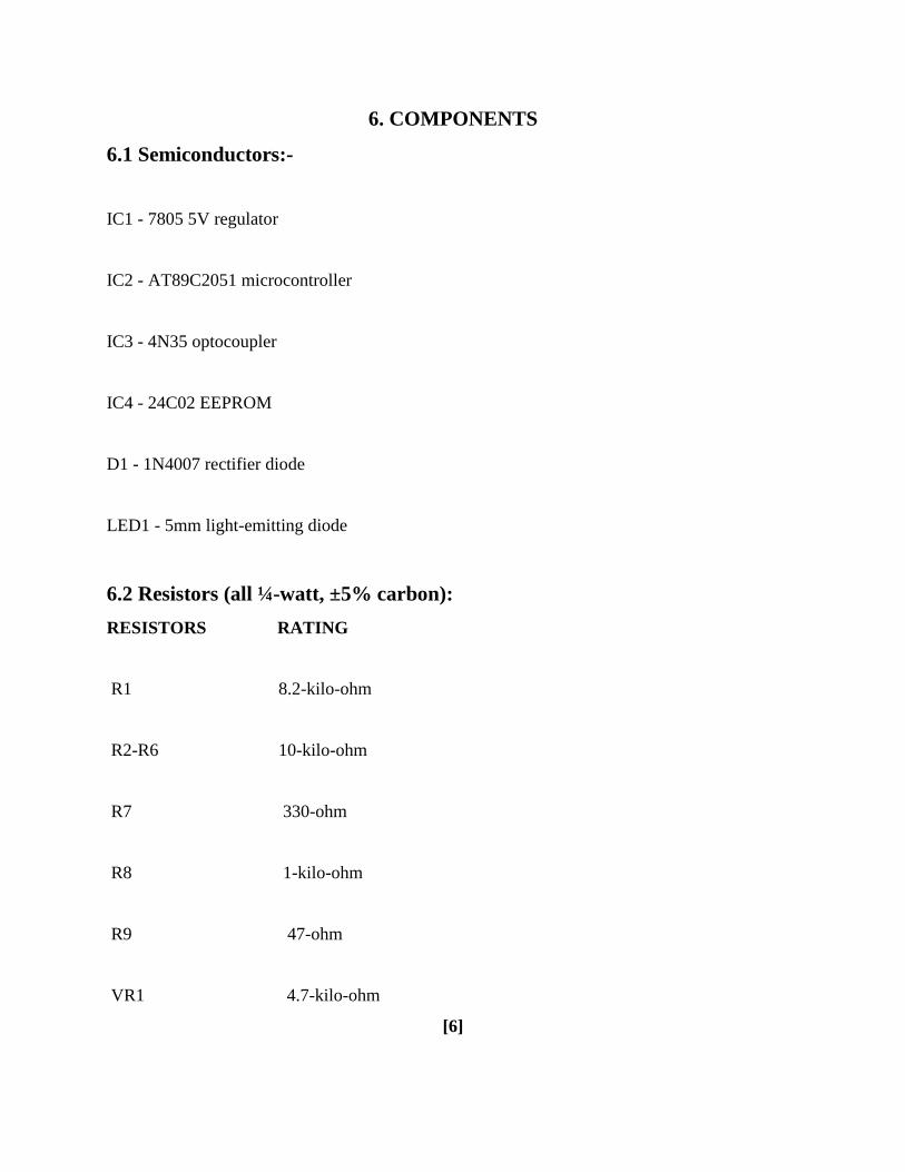
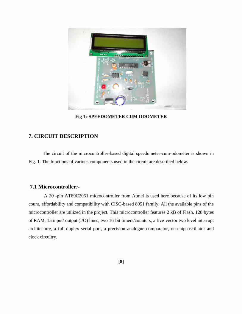
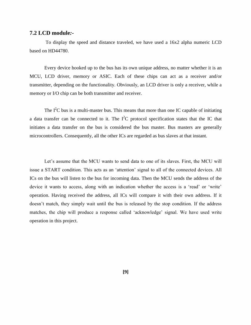
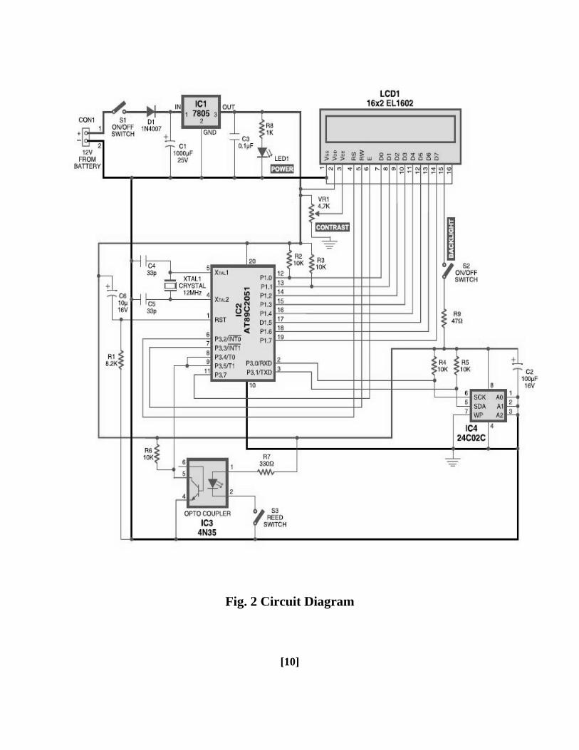
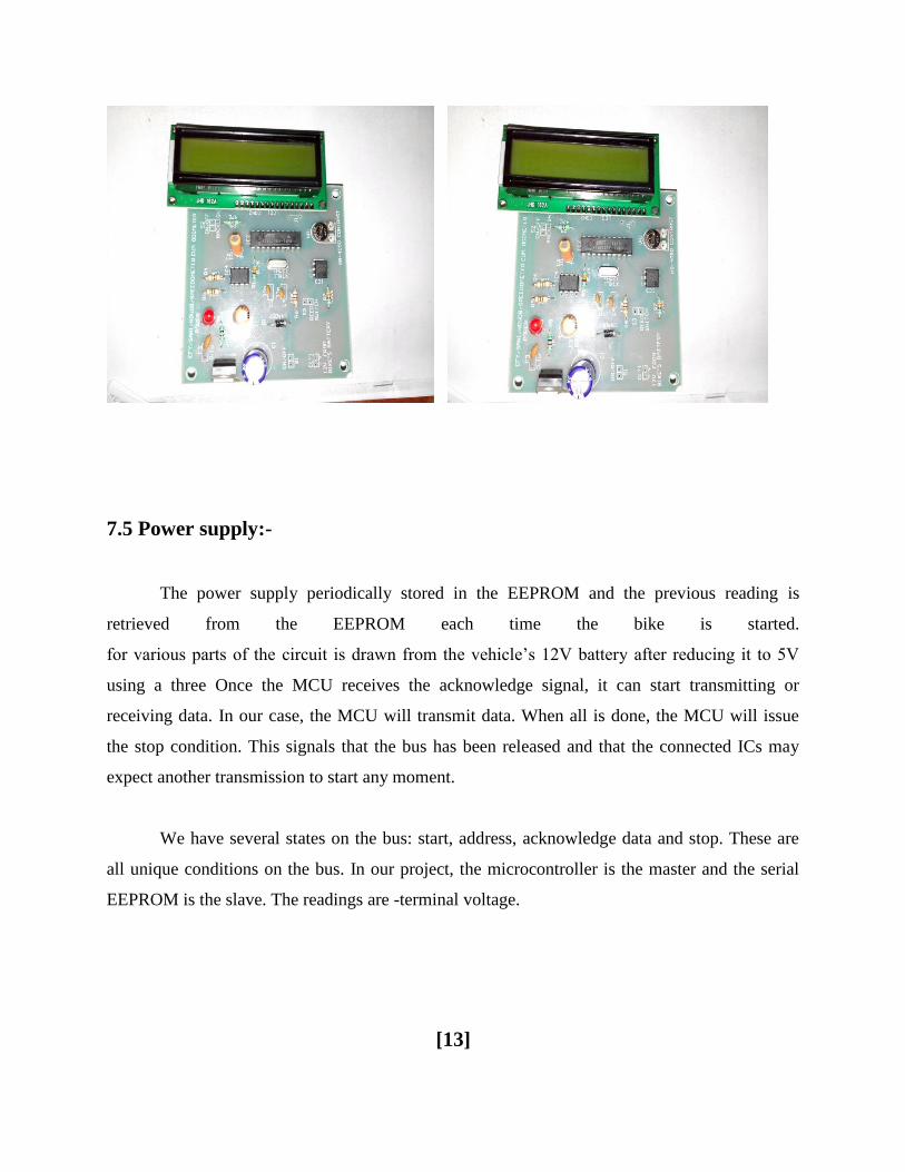
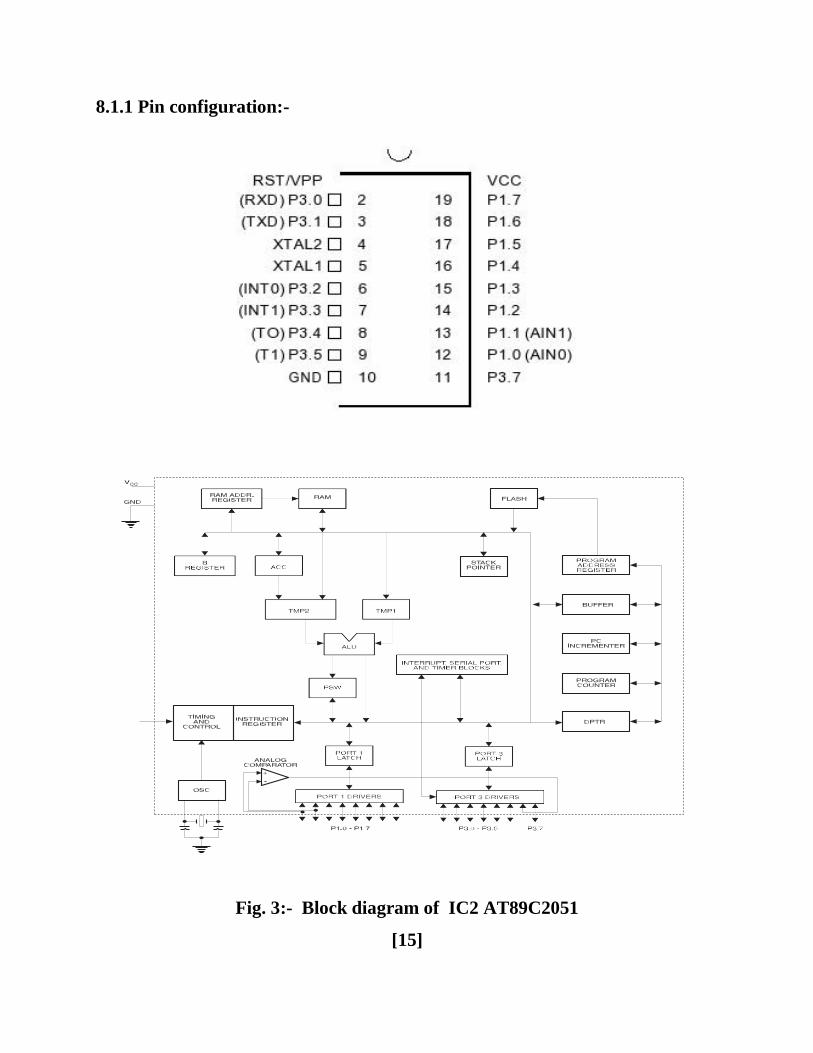
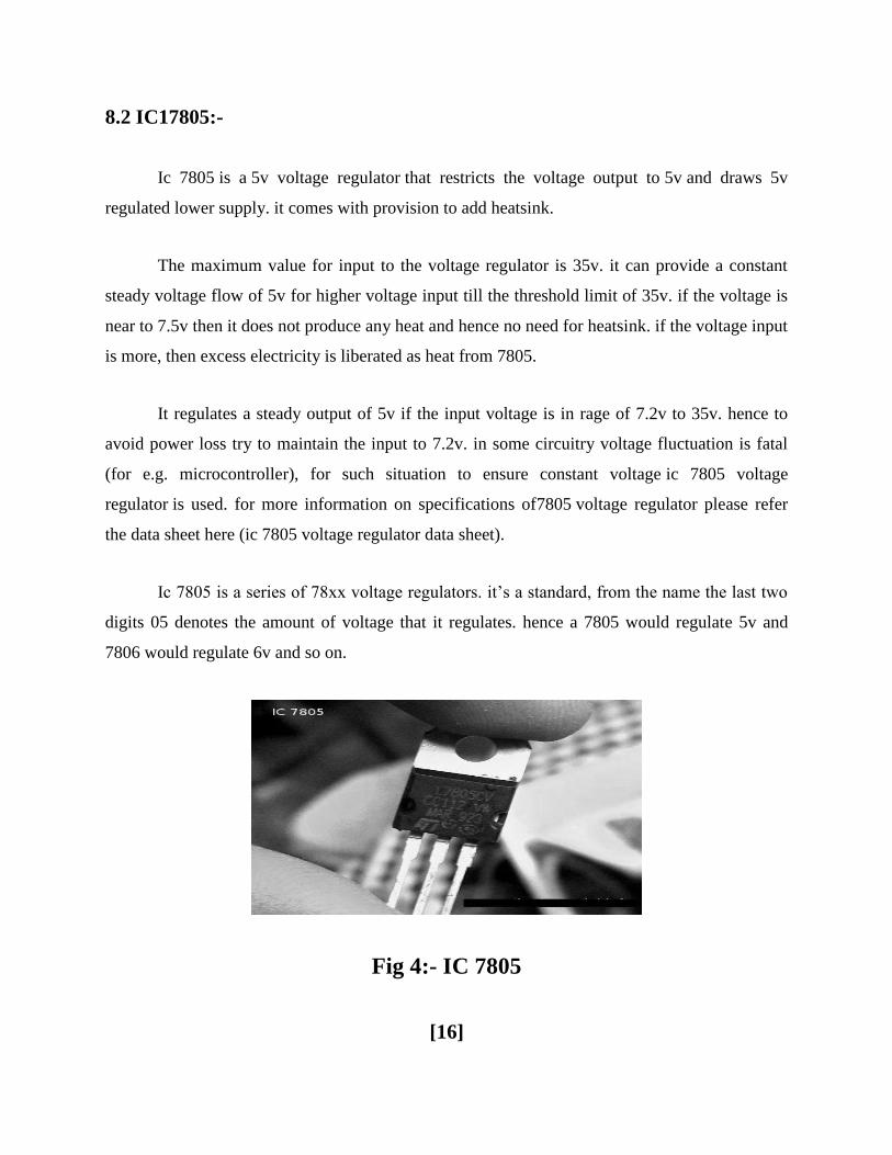
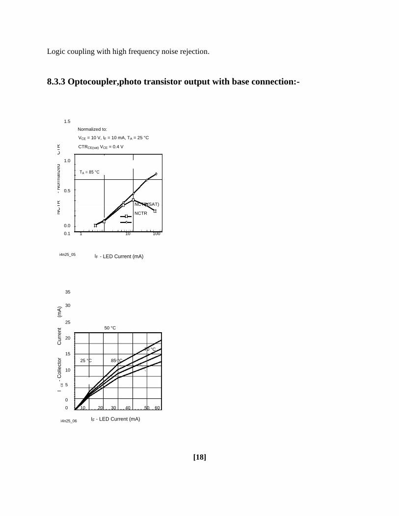
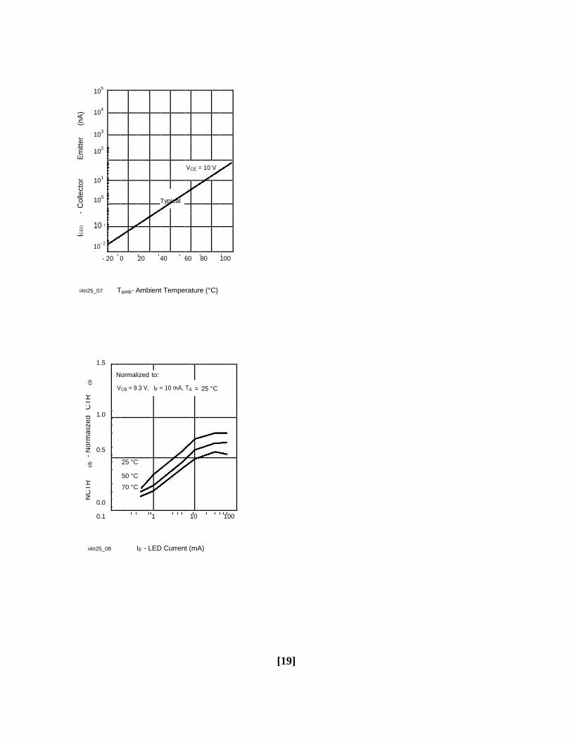
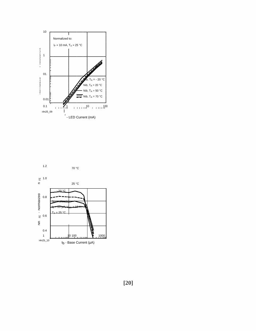
10
Photo
curr
ent
Normalized to
IF = 10 mA TA = 25 degC
1
Norm
aliz
ed
01
Nib TA = - 20 degC
Nib TA = 20 degC
Nib TA = 50 degC
001
Nib TA = 70 degC
01 1 10 100
i4n25_09 IF - LED Current (mA)
12 70 degC
FE
10
h
25 degC
Norm
aliz
ed
- 20 degC
08 Normalized to
IB = 20 microA VCE = 10 V
-
TA = 25 degC
FE
06
Nh
04
1 10 100 1000
i4n25_10 Ib - Base Current (microA)
[20]
84 LCD 162 EL102-
The most commonly used Character based LCDs are based on Hitachis HD44780
controller or other which are compatible with HD44580 In this tutorial we will discuss about
character based LCDs their interfacing with various microcontrollers various interfaces (8-bit4-
bit) programming special stuff and tricks you can do with these simple looking LCDs which
can give a new look to your application
Fig 5- LCD DISPLAY
841 Pin Description
The most commonly used LCDs found in the market today are 1 Line 2 Line or 4 Line LCDs
which have only 1 controller and support at most of 80 charachers whereas LCDs supporting
more than 80 characters make use of 2 HD44780 controllers
Most LCDs with 1 controller has 14 Pins and LCDs with 2 controller has 16 Pins (two pins are
extra in both for back-light LED connections) Pin description is shown in the table below
Pin No Name Description
1 VSS Power supply (GND)
2 VCC Power supply (+5V)
3 VEE Contrast adjust
Pin No Name Description
4 RS 0 = Instruction input
1 = Data input
5 RW 0 = Write to LCD module
1 = Read from LCD module
6 EN Enable signal
7 D0 Data bus line 0 (LSB)
8 D1 Data bus line 1
9 D2 Data bus line 2
10 D3 Data bus line 3
11 D4 Data bus line 4
12 D5 Data bus line 5
13 D6 Data bus line 6
14 D7 Data bus line zzzzzzzzzzzzz
Table 3 Character LCD pins with 1 Controller
Pin No Name Description
1 D7 Data bus line 7 (MSB)
2 D6 Data bus line 6
3 D5 Data bus line 5
4 D4 Data bus line 4
5 D3 Data bus line 3
6 D2 Data bus line 2
7 D1 Data bus line 1
8 D0 Data bus line 0 (LSB)
9 EN1 Enable signal for row 0 and 1 (1stcontroller)
10 RW 0 = Write to LCD module
1 = Read from LCD module
11 RS 0 = Instruction input
1 = Data input
12 VEE Contrast adjust
Pin No Name Description
13 VSS Power supply (GND)
14 VCC Power supply (+5V)
15 EN2 Enable signal for row 2 and 3 (2nd
controller)
16 NC Not Connected
TABLE 4 - Character LCD pins with 2 Controller
[23]
85 Light-emitting diode
A light-emitting diode (LED) (pronounced) is a semiconductor light source LEDs are
used as indicator lamps in many devices and are increasingly used for lighting Introduced as a
practical electronic component in 1962 early LEDs emitted low-intensity red light but modern
versions are available across the visible ultraviolet and infrared wavelengths with very high
brightness
Fig 6-LEDS
The LED is based on the semiconductor diode When a diode is forward biased (switched
on) electrons are able to recombine with holes within the device releasing energy in the form of
photons
This effect is called electroluminescence and the color of the light (corresponding to the
energy of the photon) is determined by the energy gap of the semiconductor
An LED is usually small in area (less than 1 mm2) and integrated optical components are
used to shape its radiation pattern and assist in reflection LEDs present many advantages over
incandescent light sources including lower energy consumption longer lifetime improved
robustness smaller size faster switching and greater durability and reliability However they
are relatively expensive and require more precise current and heat management than traditional
light sources Current LED products for general lighting are more expensive to buy than
fluorescent lamp sources of comparable output
[24]
They also enjoy use in applications as diverse as replacements for traditional light
sources in aviation lighting automotive lighting (particularly indicators) and in traffic signals
The compact size of LEDs has allowed new text and video displays and sensors to be developed
while their high switching rates are useful in advanced communications technology Infrared
LEDs are also used in the remote control units of many commercial products including
televisions DVD players and other domestic appliances
86 CAPACITORS
A capacitor (formerly known as condenser) is a passive electronic component consisting
of a pair of conductors separated by a dielectric (insulator) When a potential difference (voltage)
exists across the conductors an electric field is present in the dielectric This field stores energy
and produces a mechanical force between the conductors The effect is greatest when there is a
narrow separation between large areas of conductor hence capacitor conductors are often called
plates
An ideal capacitor is characterized by a single constant value capacitance which is
measured in farads This is the ratio of the electric charge on each conductor to the potential
difference between them In practice the dielectric between the plates passes a small amount of
leakage current The conductors and leads introduce an equivalent series resistance and the
dielectric has an electric field strength limit resulting in a breakdown voltage
Capacitors are widely used in electronic circuits to block direct current while allowing
alternating current to pass to filter out interference to smooth the output of power supplies and
for many other purposes They are used in resonant circuits in radio frequency equipment to
select particular frequencies from a signal with many frequencies
[25]
Fig 7-CAPACITORS
861 Function
Capacitors store electric charge They are used with resistors in timing circuits because it
takes time for a capacitor to fill with charge They are used to smooth varying DC supplies by
acting as a reservoir of charge They are also used in filter circuits because capacitors easily pass
AC (changing) signals but they block DC (constant) signals
862 Capacitance
This is a measure of a capacitors ability to store charge A large capacitance means that
more charge can be stored Capacitance is measured in farads symbol F However 1F is very
large so prefixes are used to show the smaller values
[26]
Three prefixes (multipliers) are used micro (micro) n (nano) and p (pico)
micro means 10-6 (millionth) so 1000000microF = 1F
n means 10-9 (thousand-millionth) so 1000nF = 1microF
p means 10-12 (million-millionth) so 1000pF = 1nF
Capacitor values can be very difficult to find because there are many types of capacitor with
different labeling systems
There are many types of capacitor but they can be split into two groups polarised and
unpolarised Each group has its own circuit symbol
Polarised capacitors (large values 1microF +)
Examples
Capacitor symble
[27]
863 Electrolytic Capacitors
Electrolytic capacitors are polarised and they must be connected
the correct way round at least one of their leads will be marked + or -
They are not damaged by heat when soldering
There are two designs of electrolytic capacitors axial where the
leads are attached to each end (220microF in picture) and radial where both
leads are at the same end (10microF in picture) Radial capacitors tend to be a little smaller and they
stand upright on the circuit board
It is easy to find the value of electrolytic capacitors because they are clearly printed with
their capacitance and voltage rating The voltage rating can be quite low (6V for example) and it
should always be checked when selecting an electrolytic capacitor
If the project parts list does not specify a voltage choose a capacitor with a rating which
is greater than the projects power supply voltage 25V is a sensible minimum most battery
circuits
[28]
864 Variable capacitors
Fig 8- Variable Capacitor
Variable capacitors are mostly used in radio tuning circuits and they are sometimes called
tuning capacitors They have very small capacitance values typically between 100pF and 500pF
(100pF = 00001microF) The type illustrated usually has trimmers built in (for making small
adjustments - see below) as well as the main variable capacitor
Many variable capacitors have very short spindles which are not suitable for the standard
knobs used for variable resistors and rotary switches It would be wise to check that a suitable
knob is available before ordering a variable capacitor
Variable capacitors are not normally used in timing circuits because their capacitance is
too small to be practical and the range of values available is very limited Instead timing circuits
use a fixed capacitor and a variable resistor if it is necessary to vary the time period
[29]
865 Trimmer capacitors
Fig 9-Trimmer Capacitor Symbol
Trimmer capacitors (trimmers) are miniature variable capacitorsThey are
designed to be mounted directly onto the circuit board and adjusted only when the circuit is built
A small screwdriver or similar tool is required to adjust trimmers
The process of adjusting them requires patience because the presence of your hand and
the tool will slightly change the capacitance of the circuit in the region of the trimmer
Trimmer capacitors are only available with very small capacitances normally less than
100pF It is impossible to reduce their capacitance to zero so they are usually specified by their
minimum and maximum values for example 2-10Pf are the capacitor equivalent of presets
which are miniature variable resistors
[30]
87 RESISTORS
A resistor is a two-terminal electronic component that produces a voltage across its
terminals that is proportional to the electric current passing through it in accordance with Ohms
law
V = IR
Resistors are elements of electrical networks and electronic circuits and are ubiquitous in
most electronic equipment Practical resistors can be made of various compounds and films as
well as resistance wire (wire made of a high-resistivity alloy such as nickelchrome)
The primary characteristics of a resistor are the resistance the tolerance maximum
working voltage and the power rating Other characteristics include temperature coefficient
noise and inductance Less well-known is critical resistance the value below which power
dissipation limits the maximum permitted current flow and above which the limit is applied
voltage Critical resistance is determined by the design materials and dimensions of the resistor
Resistors can be integrated into hybrid and printed circuits as well as integrated circuits
Size and position of leads (or terminals) are relevant to equipment designers resistors must be
physically large enough not to overheat when dissipating their power
[31]
Fig 10- RESISTORS
871 Units
The ohm (symbol Ω) is the SI unit of electrical resistance named after Georg Simon Ohm
Commonly used multiples and submultiples in electrical and electronic usage are the milliohm
(1x10minus3) kilohm (1x10³) and megohm (1x10⁶)
872 Theory of operation
Ohms law-
The behavior of an ideal resistor is dictated by the relationship specified in Ohms law
Ohms law states that the voltage (V) across a resistor is proportional to the current (I)
through it where the constant of proportionality is the resistance (R)
[32]
Equivalently Ohms law can be stated
This formulation of Ohms law states that when a voltage (V) is maintained across a
resistance (R) a current (I) will flow through the resistance
This formulation is often used in practice For example if V is 12 volts and R is 400
ohms a current of 12 400 = 003 amperes will flow through the resistance R
Fixed and Variable Resistors
There are two kinds of resistors FIXED and VARIABLE The fixed resistor will have
one value and will never change (other than through temperature age etc) The resistors shown
in A and B of figure 1-29are classed as fixed resistors
The tapped resistor illustrated in B has several fixed taps and makes more than one
resistance value available The sliding contact resistor shown in C has an adjustable collar that
can be moved to tap off any resistance within the ohmic value range of the resistor
There are two types of variable resistors one called a POTENTIOMETER and the other
a RHEOSTAT (see views D and E of fig 1-29)An example of the potentiometer is the volume
control on your radio and an example of the rheostat is the dimmer control for the dash lights in
an automobile
There is a slight difference between them Rheostats usually have two connections one
fixed and the other moveable Any variable resistor can properly be called a rheostat The
potentiometer always has three connections two fixed and one moveable Generally the rheostat
has a limited range of values and A high current-handling capability
[33]
The potentiometer has a wide range of values but it usually has a limited current-
handling capability Potentiometers are always connected as voltage dividers
Fig 11-VARIABLE RESISTORS
These are miniature versions of the standard variable resistor They are designed to be
mounted directly onto the circuit board and adjusted only when the circuit is built For example
to set the frequency of an alarm tone or the sensitivity of a light-sensitive circuit
A small screwdriver or similar tool is required to adjust presets Presets are much
cheaper than standard variable resistors so they are sometimes used in projects where a standard
variable resistor would normally be used Multi turn presets are used where very precise
adjustments must be made The screw must be turned many times (10+) to move the slider from
one end of the track to the other giving very fine control
[34]
88 TRANSFORMER
881 INTRODUCTION
A transformer is a device that transfers electrical energy from one circuit to another
through inductively coupled conductorsmdashthe transformers coils A varying current in the first or
primary winding creates a varying magnetic flux in the transformers core and thus a varying
magnetic field through the secondary winding This varying magnetic field induces a varying
electromotive force (EMF) or voltage in the secondary winding This effect is called mutual
induction
If a load is connected to the secondary an electric current will flow in the secondary
winding and electrical energy will be transferred from the primary circuit through the
transformer to the load In an ideal transformer the induced voltage in the secondary winding
(VS) is in proportion to the primary voltage (VP) and is given by the ratio of the number of turns
in the secondary (NS) to the number of turns in the primary (NP) as follows
By appropriate selection of the ratio of turns a transformer thus allows an alternating
current (AC) voltage to be stepped up by making NS greater than NP or stepped down by
making NS less than NP In the vast majority of transformers the windings are coils wound
around a ferromagnetic core air-core transformers being a notable exception
Transformers range in size from a thumbnail-sized coupling transformer hidden inside a
stage microphone to huge units weighing hundreds of tons used to interconnect portions of
power grids All operate with the same basic principles although the range of designs is wide
While new technologies have eliminated the need for transformers in some electronic circuits
transformers are still found in nearly all electronic devices designed for household (mains)
voltage Transformers are essential for high voltage power transmission which makes long
distance transmission economically practical
[35]
882 Basic principles
The transformer is based on two principles firstly that an electric current can produce a
magnetic field (electromagnetism) and secondly that a changing magnetic field within a coil of
wire induces a voltage across the ends of the coil (electromagnetic induction)
Changing the current in the primary coil changes the magnetic flux that is developed The
changing magnetic flux induces a voltage in the secondary coil
Fig 12- TRANSFORMER
883 An ideal transformer
An ideal transformer is shown in the adjacent figure Current passing through the primary
coil creates a magnetic field The primary and secondary coils are wrapped around a core of very
high magnetic permeability such as iron so that most of the magnetic flux passes through both
the primary and secondary coils
884 Induction law
The voltage induced across the secondary coil may be calculated from Faradays law of
induction which states that
[36]
where VS is the instantaneous voltage NS is the number of turns in the secondary coil
and Φ equals the magnetic flux through one turn of the coil If the turns of the coil are oriented
perpendicular to the magnetic field lines the flux is the product of the magnetic flux density B
and the area A through which it cuts
The area is constant being equal to the cross-sectional area of the transformer core
whereas the magnetic field varies with time according to the excitation of the primary Since the
same magnetic flux passes through both the primary and secondary coils in an ideal transformer
the instantaneous voltage across the primary winding equals
Taking the ratio of the two equations for VS and VP gives the basic equation for
stepping up or stepping down the voltage
885 Ideal power equation
The ideal transformer as a circuit element
[37]
If the secondary coil is attached to a load that allows current to flow electrical power is
transmitted from the primary circuit to the secondary circuit Ideally the transformer is perfectly
efficient all the incoming energy is transformed from the primary circuit to the magnetic field
and into the secondary circuit If this condition is met the incoming electric power must equal
the outgoing power
P incoming = IPVP = P outgoing = ISVS
giving the ideal transformer equation
Transformers normally have high efficiency so this formula is a reasonable approximation
If the voltage is increased then the current is decreased by the same factor The
impedance in one circuit is transformed by the square of the turnrsquos ratio For example if an
impedance ZS is attached across the terminals of the secondary coil it appears to the primary
circuit to have an impedance of This relationship is reciprocal so that the impedance ZP
of the primary circuit appears to the secondary to be
886 Operation of transformers
The simplified description above neglects several practical factors in particular the
primary current required to establish a magnetic field in the core and the contribution to the field
due to current in the secondary circuit
Models of an ideal transformer typically assume a core of negligible reluctance with two
windings of zero resistance When a voltage is applied to the primary winding a small current
flows driving flux around the magnetic circuit of the core
[38]
The current required to create the flux is termed the magnetizing current since the ideal
core has been assumed to have near-zero reluctance the magnetizing current is negligible
although still required to create the magnetic field
The changing magnetic field induces an electromotive force (EMF) across each winding
Since the ideal windings have no impedance they have no associated voltage drop and so the
voltages VP and VS measured at the terminals of the transformer are equal to the corresponding
EMFs
The primary EMF acting as it does in opposition to the primary voltage is sometimes
termed the back EMF This is due to Lenzs law which states that the induction of EMF would
always be such that it will oppose development of any such change in magnetic field
887 Practical considerations
Leakage flux
The ideal transformer model assumes that all flux generated by the primary winding links
all the turns of every winding including itself In practice some flux traverses paths that take it
outside the windings
Such flux is termed leakage flux and results in leakage inductance in series with the
mutually coupled transformer windings
[39]
Leakage results in energy being alternately stored in and discharged from the magnetic
fields with each cycle of the power supply
It is not directly a power loss (see Stray losses below) but results in inferior voltage
regulation causing the secondary voltage to fail to be directly proportional to the primary
particularly under heavy load Transformers are therefore normally designed to have very low
leakage inductance
However in some applications leakage can be a desirable property and long magnetic
paths air gaps or magnetic bypass shunts may be deliberately introduced to a transformers
design to limit the short-circuit current it will supply Leaky transformers may be used to supply
loads that exhibit negative resistance such as electric arcs mercury vapor lamps and neon signs
or for safely handling loads that become periodically short-circuited such as electric arc welders
Air gaps are also used to keep a transformer from saturating especially audio-frequency
transformers in circuits that have a direct current flowing through the windings Leakage
inductance is also helpful when transformers are operated in parallel
It can be shown that if the per-unit inductance of two transformers is the same (a
typical value is 5) they will automatically split power correctly (eg 500 KVA units in
parallel with 1000 KVA unit the larger one will carry twice the current)
888 Voltage transformers
Voltage transformers (VTs) or potential transformers (PTs) are another type of
instrument transformer used for metering and protection in high-voltage circuits They are
designed to present negligible load to the supply being measured and to have a precise voltage
ratio to accurately step down high voltages so that metering and protective relay equipment can
be operated at a lower potential
[40]
Typically the secondary of a voltage transformer is rated for 69 or 120 Volts at rated
primary voltage to match the input ratings of protection relays
Fig 13- VOLTAGE TRANSFORMER
The transformer winding high-voltage connection points are typically labeled as H1 H2
(sometimes H0 if it is internally grounded) and X1 X2 and sometimes an X3 tap may be
present Sometimes a second isolated winding (Y1 Y2 Y3) may also be available on the same
voltage transformer The high side (primary) may be connected phase to ground or phase to
phase The low side (secondary) is usually phase to ground
The terminal identifications (H1 X1 Y1 etc) are often referred to as polarity This
applies to current transformers as well At any instant terminals with the same suffix numeral
have the same polarity and phase Correct identification of terminals and wiring is essential for
proper operation of metering and protection relays
[41]
While VTs were formerly used for all voltages greater than 240V primary modern
meters eliminate the need VTs for most secondary service voltages VTs are typically used in
circuits where the system voltage level is above 600 V Modern meters eliminate the need of
VTs since the voltage remains constant and it is measured in the incoming supply
Transformer + Rectifier
The varying DC output is suitable for lamps heaters and standard motors It is not
suitable for electronic circuits unless they include a smoothing capacitor Types
Auto transformer Poly-phase transformers Leakage transformers resonant transformers
Audio transformers Instrument transformers
89 VOLTAGE REGULATOR-
A voltage regulator is designed to automatically maintain a constant voltage level A
voltage regulator may be a simple feed-forward design or may include negative
feedback control loops
[42]
It may use an electromechanical mechanism or electronic components Depending on
the design it may be used to regulate one or more AC or DC voltages
Electronic voltage regulators are found in devices such as computer power supplies where
they stabilize the DC voltages used by the processor and other elements In
automobile alternators and central power station generator plants voltage regulators control the
output of the plant In an electric power distribution system voltage regulators may be installed
at a substation or along distribution lines so that all customers receive steady voltage independent
of how much power is drawn from the line
891 MEASURES OF REGULATOR QUANTITY-
load regulation is the change in output voltage for a given change in load current (for
example typically 15 mV maximum 100 mV for load currents between 5 mA and 14 A at
some specified temperature and input voltage)
line regulation or input regulation is the degree to which output voltage changes with input
(supply) voltage changes - as a ratio of output to input change (for example typically
13 mVV) or the output voltage change over the entire specified input voltage range (for
example plus or minus 2 for input voltages between 90 V and 260 V 50-60 Hz)
Other important parameters are
Temperature coefficient of the output voltage is the change with temperature (perhaps
averaged over a given temperature range)
[43]
Initial accuracy of a voltage regulator (or simply the voltage accuracy) reflects the error in
output voltage for a fixed regulator without taking into account temperature or aging effects
on output accuracy
Dropout voltage is the minimum difference between input voltage and output voltage for
which the regulator can still supply the specified current A low drop-out (LDO) regulator is
designed to work well even with an input supply of only a volt or so above the output
voltage The input-output differential at which the voltage regulator will no longer maintain
regulation is the dropout voltage Further reduction in input voltage will result in reduced
output voltage This value is dependent on load current and junction temperature
Absolute maximum ratings are defined for regulator components specifying the continuous
and peak output currents that may be used (sometimes internally limited) the maximum
input voltage maximum power dissipation at a given temperature etc
Output noise (thermal white noise) and output dynamic impedance may be specified as
graphs versus frequency while output ripple noise (mains hum or switch-mode hash
noise) may be given as peak-to-peak or RMS voltages or in terms of their spectra
[44]
Quiescent current in a regulator circuit is the current drawn internally not available to the
load normally measured as the input current while no load is connected (and hence a source
of inefficiency some linear regulators are surprisingly more efficient at very low current
loads than switch-mode designs because of this)
Transient response is the reaction of a regulator when a (sudden) change of the load current
(called the load transient) or input voltage (called the line transient) occurs Some regulators
will tend to oscillate or have a slow response time which in some cases might lead to
undesired results This value is different from the regulation parameters as that is the stable
situation definition The transient response shows the behaviour of the regulator on a change
This data is usually provided in the technical documentation of a regulator and is also
dependent on output capacitance
Mirror-image insertion protection means that a regulator is designed for use when a voltage
usually not higher than the maximum input voltage of the regulator is applied to its output
pin while its input terminal is at a low voltage volt-free or grounded Some regulators can
continuously withstand this situation others might only manage it for a limited time such as
60 seconds as usually specified in the datasheet This situation can occur when a three
terminal regulator is incorrectly mounted for example on a PCB with the output terminal
connected to the unregulated DC input and the input connected to the load Mirror-image
insertion protection is also important when a regulator circuit is used in battery charging
circuits when external power fails or is not turned on and the output terminal remains at
battery voltage
[45]
892 ELECTRONIC VOLTAGE REGULATOR-
A simple voltage regulator can be made from a resistor in series with a diode (or series of
diodes) Due to the logarithmic shape of diode V-I curves the voltage across the diode changes
only slightly due to changes in current drawn or changes in the input When precise voltage
control and efficiency are not important this design may work fine
Feedback voltage regulators operate by comparing the actual output voltage to some
fixed reference voltage Any difference is amplified and used to control the regulation element in
such a way as to reduce the voltage error This forms a negative feedback control loop
increasing the open-loop gain tends to increase regulation accuracy but reduce stability
(Stability is avoidance of oscillation or ringing during step changes) There will also be a trade-
off between stability and the speed of the response to changes If the output voltage is too low
(perhaps due to input voltage reducing or load current increasing) the regulation element is
commanded up to a point to produce a higher output voltagendashby dropping less of the input
voltage (for linear series regulators and buck switching regulators) or to draw input current for
longer periods (boost-type switching regulators) if the output voltage is too high the regulation
element will normally be commanded to produce a lower voltage However many regulators
have over-current protection so that they will entirely stop sourcing current (or limit the current
in some way) if the output current is too high and some regulators may also shut down if the
input voltage is outside a given range (see also crowbar circuits)
[46]
893 ELECTRO MECHANICAL REGULATORS-
Fig 14- Circuit design for a simple electromechanical voltage regulator
Fig 15-A voltage stabilizer using electromechanical relays for switching
Fig 16-Graph of voltage output on a time scale
[47]
In electromechanical regulators voltage regulation is easily accomplished by coiling the
sensing wire to make an electromagnet The magnetic field produced by the current attracts a
moving ferrous core held back under spring tension or gravitational pull As voltage increases so
does the current strengthening the magnetic field produced by the coil and pulling the core
towards the field The magnet is physically connected to a mechanical power switch which
opens as the magnet moves into the field As voltage decreases so does the current releasing
spring tension or the weight of the core and causing it to retract This closes the switch and
allows the power to flow once more
If the mechanical regulator design is sensitive to small voltage fluctuations the motion of
the solenoid core can be used to move a selector switch across a range of resistances or
transformer windings to gradually step the output voltage up or down or to rotate the position of
a moving-coil AC regulator
Early automobile generators and alternators had a mechanical voltage regulator using
one two or three relays and variousresistors to stabilize the generators output at slightly more
than 6 or 12 V independent of the engines rpm or the varying load on the vehicles electrical
system Essentially the relay(s) employed pulse width modulation to regulate the output of the
generator controlling the field current reaching the generator (or alternator) and in this way
controlling the output voltage produced
The regulators used for DC generators (but not alternators) also disconnect the generator
when it was not producing electricity thereby preventing the battery from discharging back into
the generator and attempting to run it as a motor The rectifier diodes in an alternator
automatically perform this function so that a specific relay is not required this appreciably
simplified the regulator design
More modern designs now use solid state technology (transistors) to perform the same
function that the relays perform in electromechanical regulators
[48]
Electromechanical regulators are used for mains voltage stabilisation mdash see AC voltage
stabilizers below
894 AUTOMATIC VOLTAGE REGULATOR-
Fig 17-Voltage regulator for generators
To control the output of generators (as seen in ships and power stations or on oil rigs
greenhouses and emergency power systems) automatic voltage regulators are used This is an
active system While the basic principle is the same the system itself is more complex An
automatic voltage regulator (or AVR for short) consist of several components such as diodes
capacitors resistors and potentiometers or even microcontrollers all placed on a circuit board
This is then mounted near the generator and connected with several wires to measure and adjust
the generator
How an AVR works In the first place the AVR monitors the output voltage and controls
the input voltage for the exciter of the generator By increasing or decreasing the generator
control voltage the output voltage of the generator increases or decreases accordingly
[49]
The AVR calculates how much voltage has to be sent to the exciter numerous times a
second therefore stabilizing the output voltage to a predetermined setpoint When two or more
generators are powering the same system (parallel operation) the AVR receives information from
more generators to match all output
9 SOFTWARE-
The lsquoInit_EEPROMrsquo and lsquoSpeedorsquo source codes of this project are written in Assembly
language These are compiled using an open-source ASEM-51 assembler to generate the
Init_EEPROMhex and Speedohex files The hex files are burnt into the microcontroller chip
Two internal timers of the microcontroller are configured as 8-bit counters to count the number
of pulses generated by the speed sensor One timer is used to measure the distance and the other
for speed calculation A software delay of one second is generated after the speed counter is
triggered The speed count value is obtained from the counter registers To speed up the process
a look-up data table is stored in the ROM that helps the microcontroller to convert the number of
pulses into the corresponding speed values
The program flow-chart is shown in Fig 2 The lsquodistancersquo counter is incremented every
100 metres The wheel has to make 53 revolutions to achieve this The distance counter is loaded
with an initial value of 203 (255-53+1) and is incremented on each revolution After 53 counts
the timer overflows and generates an interrupt to notify the microcontroller that 100 metres are
covered In the interrupt service routine the microcontroller updates the corresponding lsquoDS1rsquo
distance variable Instead of saving distance variables after each cycle the microcontroller saves
these readings when the vehicle is at halt (speed is 000 kmhour) In other words when the
vehicle is stopped at traffic signals or before the ignition key is turned off the last reading is
saved to the EEPROM The same reading again retrieved from the EEPROM when the bike is
turned on next time and the readings are updated for each trip
[50]
91 Program can be used-
includeat89x52h
includelcdh
includelt24cxxcgt
unsigned char val=0x00
unsigned int distance=0speed=0cal=0
unsigned char km=0t=0
void timer0(void) interrupt 1
t++
distance=distance+100
if(distance==1000)
km=km+1
t=0
distance=0
[51]
void one_sec()
unsigned int ij
for(i=0ilt120i++)
for(j=0jlt1271j++)
void display(int num)
unsigned char tuf
t=num10
num=num10
[52]
u=num10
num=num10
f=num10
lcd_data(0+f)
lcd_data(0+u)
lcd_data(0+t)
void bintoascii(unsigned char value)
unsigned char xd1d2d3abc
x=value10
d1=value10
d2=x10
d3=x10
a=0x30|d1
b=0x30|d2
c=0x30|d3
lcd_data( )
[53]
lcd_data(c)
lcd_data(b)
lcd_data(a)
lcd_com(0xc0)
lcd_puts(KM )
display(km)
lcd_puts( MT )
display(distance)
void main()
unsigned char c=0d=0
T1=1
T0=1
TMOD=0x66
TH0=206
TL0=206
TH1=0
[54]
TL1=0
TR0=1
P1=0xFF
IE=0x82
RW24XX(ampc 1 1 0xA1 M2404)
RW24XX(ampd 1 4 0xA1 M2404)
t=d
km=c
distance=t100
c=0d=0
lcd_init()
lcd_com(0x01)
lcd_com(0x0C)
lcd_com(0x80)
while(1)
TR0=1
val=TL0
[55]
TL1=0
TR1=1
one_sec()
speed=TL1
TR1=0
cal=(speed7)
lcd_com(0x80)
lcd_puts(Speed )
display(cal)
lcd_com(0x89)
lcd_data( )
bintoascii(val)
if(speed==0)
c=km
d=t
RW24XX(ampc 1 1 0xA0 M2404)
RW24XX(ampd 1 4 0xA0 M2404)
[56]
if(P1_4==0)
while(P1_4=1)
c=0
RW24XX(ampc 2 1 0xA0 M2404)
[57]
Fig 18- Flow Chart
[58]
10 CONSTRUCTION-
The reed switch and a magnet need to be fixed on the front wheel of the motor bike
(Hero Hondarsquos Splendor)
A small circular magnet(about 2 cm in diametre) normally used in speakers of small
toys can be used Fix the magnet to the cen- tral drum of the wheel just below the spokes
connected to the drum Secure the magnet using hot glue or Araldite For fixing the reed switch
a PVC pipe contraption needs to be made so that the magnet and reed switch are aligned as
shown in Fig 3 The materials required to build the con- traption are shown in Fig 4 Cut a
32cm diameter PVC pipe measuring 152 cm in length perpendicularly into two halves Use
only one half of the PVC pipe Mount and secure the reed switch using Araldite and cable ties on
the plastic handle (normally used in emergency lights) Once it dries up solder two wires to the
two opposite end leads of the reed switch Fix the plastic handle on the half cut PVC pipe using
screws Now place the pipe on the front shock-absorber fork such that reed switch faces to-
wards the magnet Connect a multimeter set in continuity mode to the two wires coming from
the reed switch Rotate the wheel slowly and see whether the reed switch closes when the magnet
passes across it If it does the multimeter will give a continuity beep
When the magnet moves away from the reed switch the beep will stop indicating that
the reed switch is open Make a few trials to find the optimal position for mounting and fixing
the PVC pipe such that the reed switch works smoothly Mark the location on the front shock-ab-
sorber fork
Now you can fix the PVC pipe contraption to the shock-ab- sorber fork us- ing hot glue
as shown in Fig 5 Use liberal amount of hot glue to secure it to the pipe Care- fully route the
two wires up to the bikersquos handle bar using cable ties to secure the wire This com- pletes the
sensor mounting part The main cir- cuit and the LCD module can be housed in suit- able plastic
en- closures which are readily avail- able in electronic projects shops
[59]
These enclosures should have precut slot for easy mounting of the LCD pan- el If such
boxes are not available you can use the plastic boxes of electronic chokes by suitably re- moving
some portions for the LCD panel Power sup- ply can be taken either directly from the bikersquos
12V battery or tapped from the console which houses horn head- light and indicator light
switches For this you need to remove the switch console and identify positive wire and ground
wire using a mul- timeter When carrying out this step remember to turn the ignition key to lsquoonrsquo
position Solder a 60cm two-core wire to the positive and negative terminals inside the switch
console The advantage of taking supply from the switch console is that the ignition key controls
the power supply to the main unit without having a separate on-off switch An actual-size
single-side PCB layout of the microcontroller-based speedometer-cum-odometer is shown in Fig
16 and its component layout in Fig 17
Fig 19-Component layout for PCB
11 TESTING-
After all the components are soldered on the PCB program the microcon- troller with
Init_EEPROMhex file and place the microcontroller in a 20-pin IC base and switch on the
circuit In the first line of the LCD lsquoINIT_EEPROMrsquo appears After five seconds lsquo000000rsquo is
displayed in the second line This process erases any previous data and sets the initial readings in
the EEPROM to zero Now switch off the supply and program the microcontroller with
lsquospeedohexrsquo main file After pro- gramming place the microcontroller back in the circuit and
switch on the supply The LCD will show lsquoKms 000000rsquo in the first line and lsquoSpeed- KmsHr
000rsquo in the second line Now the unit is ready to mount on your bike Connect the two wires
coming from the reed switch and the power supply wires to the main unit Mount the unit at the
centre of the bikersquos handle bar on top of the lsquoUrsquo clamps that secure the handle bar to the chassis
You can use cable ties to accomplish this Mounting arrange- ment of the unit is shown in Fig 6
Now start the bike take a test ride and if connections are correct the speed and the distance will
be displayed on the LCD
[61]
A protective cover like polythene can be used for the main unit on rainy days EFY note
The source codes for this article have been included in this monthrsquos EFY-CD
111 Calculations-
You first need to know the radius of the bikersquos front wheel The calculations here are
based on Hero Hondarsquos Splendor model The radius of the front wheel is 30 cm (This can vary
with the
brand or model) Circumference of the wheel= 2πr (where lsquorrsquo is in cm) = 2times314times30 = 1884 cm
or 1884 meters
1111 Speed-
Letrsquos assume that in 1 second the wheel completes one revolution In other words in one
second the bike has covered 188 metres Therefore the speed in kmhour Ntimes188times36001000 =
Ntimes6784 or Ntimes68 where lsquoNrsquo is the number of revolutions per second lsquo68rsquo is a constant and
only lsquoNrsquo varies for example if lsquoNrsquo is 5 the speed equals 5x68= 34 kmhour
1112 Distance-
The odometer is updated every 100 metres To cover 100 metres the wheel is required to
make approximately 53 revolutions (100188) The microcontroller takes care of the tasks of
revolutions counting speed calculation conversion and display of results
[62]
12 FEATURES-
[1] Digital read out
[2] Speed displayed in kmhr
[3] Distance travelled displayed in km
[4] Readings saved in non volatile memory
[5] Realibility due to use of the microcontroller
[6] No mechanical wear amp tear
[7] Home-brewed speed transducer or sensor
[8] Self reset to zero after completion of 999999km
[9] Easy to built amp fix on the bike
[63]
13 APPLICATION-
[1] It is in luxury cars and motor bike
[2] It is used to measured speed of the motor bike
[3] It measures speed amp quantity of fuel
[4] It is used to counting revolution and speed calculation of cars
[5] It is for conversion of speed and display results
Fig 20- APPLICATION
[64]
14 CONCLUSION-
Considering the total requirement and need of society as well as according to cost
analysis and project profitability statement it is concluded that the project Microcontroller based
speedometer-cum-odometer is technically viable financially feasible and suitable for speed
measurement
[65]
15REFERENCES
[1] B Ravindranath M Chander Power System Protection and Switchgear NEW AGE
INTERNATIONAL PUBLISHERS 2nd
edition 2011 pp31-39148-153255-385
[2] A Chakrabarti M L Soni A Text Book ON POWER SYSTEM ENGINEERING
Dhanpat Rai amp CO 2nd
edition 2010 pp539-578579-616617-632
[3] B L Theraja A K Theraja A Text Book ON ELECTRICAL MACHINES S CHAND
PUBLICATION 1st edition 2005 pp1243-1312
[4] Ashfaq Hussain ELECTRICAL MACHINES DHANPAT RAI ampCO 2nd
edition
2005pp307-416
[5] V K Mehta Rohit Mehta Principles of ELECTRICAL MACHINES S CHAND
PUBLICATION 1st edition 2002 pp313-377
[6] J B Gupta THEORY amp PERFORMANCE of ELECTRICAL MACHINES S K
KATARIA amp SONS 14th
edition 2006 pp359-439
[7] Yang ES ―Fundamentals of Semiconductor Devices chap 1 McGraw Hill Book
Company New York 1978
[8] wwwgooglecom
[9] wwwieeeorg
[10] Wikipedia- httpsenwikipediaorgwikiElectronic_component
[11] All Electronics- wwwallelectronicscom
[12] wwwelectrical4ucom
[13] wwwelectricalengineeringschoolsorg
[14] EFY- httpswwwelectronicsforucom
[15] wwwelectrical-engineering-portalcom
[16] wwwrealworldengineeringorg
[66]
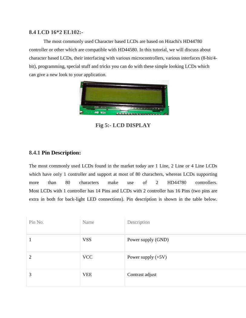
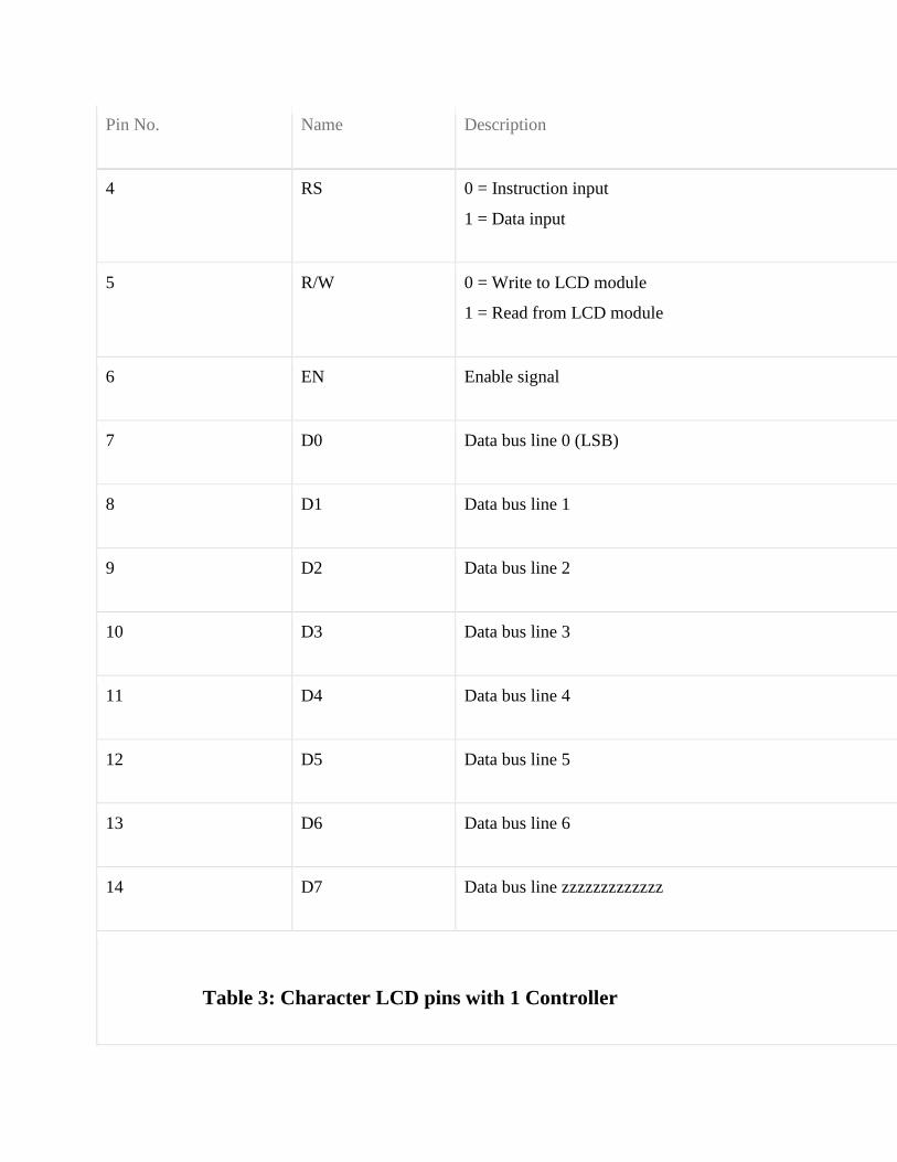
Pin No Name Description
4 RS 0 = Instruction input
1 = Data input
5 RW 0 = Write to LCD module
1 = Read from LCD module
6 EN Enable signal
7 D0 Data bus line 0 (LSB)
8 D1 Data bus line 1
9 D2 Data bus line 2
10 D3 Data bus line 3
11 D4 Data bus line 4
12 D5 Data bus line 5
13 D6 Data bus line 6
14 D7 Data bus line zzzzzzzzzzzzz
Table 3 Character LCD pins with 1 Controller
Pin No Name Description
1 D7 Data bus line 7 (MSB)
2 D6 Data bus line 6
3 D5 Data bus line 5
4 D4 Data bus line 4
5 D3 Data bus line 3
6 D2 Data bus line 2
7 D1 Data bus line 1
8 D0 Data bus line 0 (LSB)
9 EN1 Enable signal for row 0 and 1 (1stcontroller)
10 RW 0 = Write to LCD module
1 = Read from LCD module
11 RS 0 = Instruction input
1 = Data input
12 VEE Contrast adjust
Pin No Name Description
13 VSS Power supply (GND)
14 VCC Power supply (+5V)
15 EN2 Enable signal for row 2 and 3 (2nd
controller)
16 NC Not Connected
TABLE 4 - Character LCD pins with 2 Controller
[23]
85 Light-emitting diode
A light-emitting diode (LED) (pronounced) is a semiconductor light source LEDs are
used as indicator lamps in many devices and are increasingly used for lighting Introduced as a
practical electronic component in 1962 early LEDs emitted low-intensity red light but modern
versions are available across the visible ultraviolet and infrared wavelengths with very high
brightness
Fig 6-LEDS
The LED is based on the semiconductor diode When a diode is forward biased (switched
on) electrons are able to recombine with holes within the device releasing energy in the form of
photons
This effect is called electroluminescence and the color of the light (corresponding to the
energy of the photon) is determined by the energy gap of the semiconductor
An LED is usually small in area (less than 1 mm2) and integrated optical components are
used to shape its radiation pattern and assist in reflection LEDs present many advantages over
incandescent light sources including lower energy consumption longer lifetime improved
robustness smaller size faster switching and greater durability and reliability However they
are relatively expensive and require more precise current and heat management than traditional
light sources Current LED products for general lighting are more expensive to buy than
fluorescent lamp sources of comparable output
[24]
They also enjoy use in applications as diverse as replacements for traditional light
sources in aviation lighting automotive lighting (particularly indicators) and in traffic signals
The compact size of LEDs has allowed new text and video displays and sensors to be developed
while their high switching rates are useful in advanced communications technology Infrared
LEDs are also used in the remote control units of many commercial products including
televisions DVD players and other domestic appliances
86 CAPACITORS
A capacitor (formerly known as condenser) is a passive electronic component consisting
of a pair of conductors separated by a dielectric (insulator) When a potential difference (voltage)
exists across the conductors an electric field is present in the dielectric This field stores energy
and produces a mechanical force between the conductors The effect is greatest when there is a
narrow separation between large areas of conductor hence capacitor conductors are often called
plates
An ideal capacitor is characterized by a single constant value capacitance which is
measured in farads This is the ratio of the electric charge on each conductor to the potential
difference between them In practice the dielectric between the plates passes a small amount of
leakage current The conductors and leads introduce an equivalent series resistance and the
dielectric has an electric field strength limit resulting in a breakdown voltage
Capacitors are widely used in electronic circuits to block direct current while allowing
alternating current to pass to filter out interference to smooth the output of power supplies and
for many other purposes They are used in resonant circuits in radio frequency equipment to
select particular frequencies from a signal with many frequencies
[25]
Fig 7-CAPACITORS
861 Function
Capacitors store electric charge They are used with resistors in timing circuits because it
takes time for a capacitor to fill with charge They are used to smooth varying DC supplies by
acting as a reservoir of charge They are also used in filter circuits because capacitors easily pass
AC (changing) signals but they block DC (constant) signals
862 Capacitance
This is a measure of a capacitors ability to store charge A large capacitance means that
more charge can be stored Capacitance is measured in farads symbol F However 1F is very
large so prefixes are used to show the smaller values
[26]
Three prefixes (multipliers) are used micro (micro) n (nano) and p (pico)
micro means 10-6 (millionth) so 1000000microF = 1F
n means 10-9 (thousand-millionth) so 1000nF = 1microF
p means 10-12 (million-millionth) so 1000pF = 1nF
Capacitor values can be very difficult to find because there are many types of capacitor with
different labeling systems
There are many types of capacitor but they can be split into two groups polarised and
unpolarised Each group has its own circuit symbol
Polarised capacitors (large values 1microF +)
Examples
Capacitor symble
[27]
863 Electrolytic Capacitors
Electrolytic capacitors are polarised and they must be connected
the correct way round at least one of their leads will be marked + or -
They are not damaged by heat when soldering
There are two designs of electrolytic capacitors axial where the
leads are attached to each end (220microF in picture) and radial where both
leads are at the same end (10microF in picture) Radial capacitors tend to be a little smaller and they
stand upright on the circuit board
It is easy to find the value of electrolytic capacitors because they are clearly printed with
their capacitance and voltage rating The voltage rating can be quite low (6V for example) and it
should always be checked when selecting an electrolytic capacitor
If the project parts list does not specify a voltage choose a capacitor with a rating which
is greater than the projects power supply voltage 25V is a sensible minimum most battery
circuits
[28]
864 Variable capacitors
Fig 8- Variable Capacitor
Variable capacitors are mostly used in radio tuning circuits and they are sometimes called
tuning capacitors They have very small capacitance values typically between 100pF and 500pF
(100pF = 00001microF) The type illustrated usually has trimmers built in (for making small
adjustments - see below) as well as the main variable capacitor
Many variable capacitors have very short spindles which are not suitable for the standard
knobs used for variable resistors and rotary switches It would be wise to check that a suitable
knob is available before ordering a variable capacitor
Variable capacitors are not normally used in timing circuits because their capacitance is
too small to be practical and the range of values available is very limited Instead timing circuits
use a fixed capacitor and a variable resistor if it is necessary to vary the time period
[29]
865 Trimmer capacitors
Fig 9-Trimmer Capacitor Symbol
Trimmer capacitors (trimmers) are miniature variable capacitorsThey are
designed to be mounted directly onto the circuit board and adjusted only when the circuit is built
A small screwdriver or similar tool is required to adjust trimmers
The process of adjusting them requires patience because the presence of your hand and
the tool will slightly change the capacitance of the circuit in the region of the trimmer
Trimmer capacitors are only available with very small capacitances normally less than
100pF It is impossible to reduce their capacitance to zero so they are usually specified by their
minimum and maximum values for example 2-10Pf are the capacitor equivalent of presets
which are miniature variable resistors
[30]
87 RESISTORS
A resistor is a two-terminal electronic component that produces a voltage across its
terminals that is proportional to the electric current passing through it in accordance with Ohms
law
V = IR
Resistors are elements of electrical networks and electronic circuits and are ubiquitous in
most electronic equipment Practical resistors can be made of various compounds and films as
well as resistance wire (wire made of a high-resistivity alloy such as nickelchrome)
The primary characteristics of a resistor are the resistance the tolerance maximum
working voltage and the power rating Other characteristics include temperature coefficient
noise and inductance Less well-known is critical resistance the value below which power
dissipation limits the maximum permitted current flow and above which the limit is applied
voltage Critical resistance is determined by the design materials and dimensions of the resistor
Resistors can be integrated into hybrid and printed circuits as well as integrated circuits
Size and position of leads (or terminals) are relevant to equipment designers resistors must be
physically large enough not to overheat when dissipating their power
[31]
Fig 10- RESISTORS
871 Units
The ohm (symbol Ω) is the SI unit of electrical resistance named after Georg Simon Ohm
Commonly used multiples and submultiples in electrical and electronic usage are the milliohm
(1x10minus3) kilohm (1x10³) and megohm (1x10⁶)
872 Theory of operation
Ohms law-
The behavior of an ideal resistor is dictated by the relationship specified in Ohms law
Ohms law states that the voltage (V) across a resistor is proportional to the current (I)
through it where the constant of proportionality is the resistance (R)
[32]
Equivalently Ohms law can be stated
This formulation of Ohms law states that when a voltage (V) is maintained across a
resistance (R) a current (I) will flow through the resistance
This formulation is often used in practice For example if V is 12 volts and R is 400
ohms a current of 12 400 = 003 amperes will flow through the resistance R
Fixed and Variable Resistors
There are two kinds of resistors FIXED and VARIABLE The fixed resistor will have
one value and will never change (other than through temperature age etc) The resistors shown
in A and B of figure 1-29are classed as fixed resistors
The tapped resistor illustrated in B has several fixed taps and makes more than one
resistance value available The sliding contact resistor shown in C has an adjustable collar that
can be moved to tap off any resistance within the ohmic value range of the resistor
There are two types of variable resistors one called a POTENTIOMETER and the other
a RHEOSTAT (see views D and E of fig 1-29)An example of the potentiometer is the volume
control on your radio and an example of the rheostat is the dimmer control for the dash lights in
an automobile
There is a slight difference between them Rheostats usually have two connections one
fixed and the other moveable Any variable resistor can properly be called a rheostat The
potentiometer always has three connections two fixed and one moveable Generally the rheostat
has a limited range of values and A high current-handling capability
[33]
The potentiometer has a wide range of values but it usually has a limited current-
handling capability Potentiometers are always connected as voltage dividers
Fig 11-VARIABLE RESISTORS
These are miniature versions of the standard variable resistor They are designed to be
mounted directly onto the circuit board and adjusted only when the circuit is built For example
to set the frequency of an alarm tone or the sensitivity of a light-sensitive circuit
A small screwdriver or similar tool is required to adjust presets Presets are much
cheaper than standard variable resistors so they are sometimes used in projects where a standard
variable resistor would normally be used Multi turn presets are used where very precise
adjustments must be made The screw must be turned many times (10+) to move the slider from
one end of the track to the other giving very fine control
[34]
88 TRANSFORMER
881 INTRODUCTION
A transformer is a device that transfers electrical energy from one circuit to another
through inductively coupled conductorsmdashthe transformers coils A varying current in the first or
primary winding creates a varying magnetic flux in the transformers core and thus a varying
magnetic field through the secondary winding This varying magnetic field induces a varying
electromotive force (EMF) or voltage in the secondary winding This effect is called mutual
induction
If a load is connected to the secondary an electric current will flow in the secondary
winding and electrical energy will be transferred from the primary circuit through the
transformer to the load In an ideal transformer the induced voltage in the secondary winding
(VS) is in proportion to the primary voltage (VP) and is given by the ratio of the number of turns
in the secondary (NS) to the number of turns in the primary (NP) as follows
By appropriate selection of the ratio of turns a transformer thus allows an alternating
current (AC) voltage to be stepped up by making NS greater than NP or stepped down by
making NS less than NP In the vast majority of transformers the windings are coils wound
around a ferromagnetic core air-core transformers being a notable exception
Transformers range in size from a thumbnail-sized coupling transformer hidden inside a
stage microphone to huge units weighing hundreds of tons used to interconnect portions of
power grids All operate with the same basic principles although the range of designs is wide
While new technologies have eliminated the need for transformers in some electronic circuits
transformers are still found in nearly all electronic devices designed for household (mains)
voltage Transformers are essential for high voltage power transmission which makes long
distance transmission economically practical
[35]
882 Basic principles
The transformer is based on two principles firstly that an electric current can produce a
magnetic field (electromagnetism) and secondly that a changing magnetic field within a coil of
wire induces a voltage across the ends of the coil (electromagnetic induction)
Changing the current in the primary coil changes the magnetic flux that is developed The
changing magnetic flux induces a voltage in the secondary coil
Fig 12- TRANSFORMER
883 An ideal transformer
An ideal transformer is shown in the adjacent figure Current passing through the primary
coil creates a magnetic field The primary and secondary coils are wrapped around a core of very
high magnetic permeability such as iron so that most of the magnetic flux passes through both
the primary and secondary coils
884 Induction law
The voltage induced across the secondary coil may be calculated from Faradays law of
induction which states that
[36]
where VS is the instantaneous voltage NS is the number of turns in the secondary coil
and Φ equals the magnetic flux through one turn of the coil If the turns of the coil are oriented
perpendicular to the magnetic field lines the flux is the product of the magnetic flux density B
and the area A through which it cuts
The area is constant being equal to the cross-sectional area of the transformer core
whereas the magnetic field varies with time according to the excitation of the primary Since the
same magnetic flux passes through both the primary and secondary coils in an ideal transformer
the instantaneous voltage across the primary winding equals
Taking the ratio of the two equations for VS and VP gives the basic equation for
stepping up or stepping down the voltage
885 Ideal power equation
The ideal transformer as a circuit element
[37]
If the secondary coil is attached to a load that allows current to flow electrical power is
transmitted from the primary circuit to the secondary circuit Ideally the transformer is perfectly
efficient all the incoming energy is transformed from the primary circuit to the magnetic field
and into the secondary circuit If this condition is met the incoming electric power must equal
the outgoing power
P incoming = IPVP = P outgoing = ISVS
giving the ideal transformer equation
Transformers normally have high efficiency so this formula is a reasonable approximation
If the voltage is increased then the current is decreased by the same factor The
impedance in one circuit is transformed by the square of the turnrsquos ratio For example if an
impedance ZS is attached across the terminals of the secondary coil it appears to the primary
circuit to have an impedance of This relationship is reciprocal so that the impedance ZP
of the primary circuit appears to the secondary to be
886 Operation of transformers
The simplified description above neglects several practical factors in particular the
primary current required to establish a magnetic field in the core and the contribution to the field
due to current in the secondary circuit
Models of an ideal transformer typically assume a core of negligible reluctance with two
windings of zero resistance When a voltage is applied to the primary winding a small current
flows driving flux around the magnetic circuit of the core
[38]
The current required to create the flux is termed the magnetizing current since the ideal
core has been assumed to have near-zero reluctance the magnetizing current is negligible
although still required to create the magnetic field
The changing magnetic field induces an electromotive force (EMF) across each winding
Since the ideal windings have no impedance they have no associated voltage drop and so the
voltages VP and VS measured at the terminals of the transformer are equal to the corresponding
EMFs
The primary EMF acting as it does in opposition to the primary voltage is sometimes
termed the back EMF This is due to Lenzs law which states that the induction of EMF would
always be such that it will oppose development of any such change in magnetic field
887 Practical considerations
Leakage flux
The ideal transformer model assumes that all flux generated by the primary winding links
all the turns of every winding including itself In practice some flux traverses paths that take it
outside the windings
Such flux is termed leakage flux and results in leakage inductance in series with the
mutually coupled transformer windings
[39]
Leakage results in energy being alternately stored in and discharged from the magnetic
fields with each cycle of the power supply
It is not directly a power loss (see Stray losses below) but results in inferior voltage
regulation causing the secondary voltage to fail to be directly proportional to the primary
particularly under heavy load Transformers are therefore normally designed to have very low
leakage inductance
However in some applications leakage can be a desirable property and long magnetic
paths air gaps or magnetic bypass shunts may be deliberately introduced to a transformers
design to limit the short-circuit current it will supply Leaky transformers may be used to supply
loads that exhibit negative resistance such as electric arcs mercury vapor lamps and neon signs
or for safely handling loads that become periodically short-circuited such as electric arc welders
Air gaps are also used to keep a transformer from saturating especially audio-frequency
transformers in circuits that have a direct current flowing through the windings Leakage
inductance is also helpful when transformers are operated in parallel
It can be shown that if the per-unit inductance of two transformers is the same (a
typical value is 5) they will automatically split power correctly (eg 500 KVA units in
parallel with 1000 KVA unit the larger one will carry twice the current)
888 Voltage transformers
Voltage transformers (VTs) or potential transformers (PTs) are another type of
instrument transformer used for metering and protection in high-voltage circuits They are
designed to present negligible load to the supply being measured and to have a precise voltage
ratio to accurately step down high voltages so that metering and protective relay equipment can
be operated at a lower potential
[40]
Typically the secondary of a voltage transformer is rated for 69 or 120 Volts at rated
primary voltage to match the input ratings of protection relays
Fig 13- VOLTAGE TRANSFORMER
The transformer winding high-voltage connection points are typically labeled as H1 H2
(sometimes H0 if it is internally grounded) and X1 X2 and sometimes an X3 tap may be
present Sometimes a second isolated winding (Y1 Y2 Y3) may also be available on the same
voltage transformer The high side (primary) may be connected phase to ground or phase to
phase The low side (secondary) is usually phase to ground
The terminal identifications (H1 X1 Y1 etc) are often referred to as polarity This
applies to current transformers as well At any instant terminals with the same suffix numeral
have the same polarity and phase Correct identification of terminals and wiring is essential for
proper operation of metering and protection relays
[41]
While VTs were formerly used for all voltages greater than 240V primary modern
meters eliminate the need VTs for most secondary service voltages VTs are typically used in
circuits where the system voltage level is above 600 V Modern meters eliminate the need of
VTs since the voltage remains constant and it is measured in the incoming supply
Transformer + Rectifier
The varying DC output is suitable for lamps heaters and standard motors It is not
suitable for electronic circuits unless they include a smoothing capacitor Types
Auto transformer Poly-phase transformers Leakage transformers resonant transformers
Audio transformers Instrument transformers
89 VOLTAGE REGULATOR-
A voltage regulator is designed to automatically maintain a constant voltage level A
voltage regulator may be a simple feed-forward design or may include negative
feedback control loops
[42]
It may use an electromechanical mechanism or electronic components Depending on
the design it may be used to regulate one or more AC or DC voltages
Electronic voltage regulators are found in devices such as computer power supplies where
they stabilize the DC voltages used by the processor and other elements In
automobile alternators and central power station generator plants voltage regulators control the
output of the plant In an electric power distribution system voltage regulators may be installed
at a substation or along distribution lines so that all customers receive steady voltage independent
of how much power is drawn from the line
891 MEASURES OF REGULATOR QUANTITY-
load regulation is the change in output voltage for a given change in load current (for
example typically 15 mV maximum 100 mV for load currents between 5 mA and 14 A at
some specified temperature and input voltage)
line regulation or input regulation is the degree to which output voltage changes with input
(supply) voltage changes - as a ratio of output to input change (for example typically
13 mVV) or the output voltage change over the entire specified input voltage range (for
example plus or minus 2 for input voltages between 90 V and 260 V 50-60 Hz)
Other important parameters are
Temperature coefficient of the output voltage is the change with temperature (perhaps
averaged over a given temperature range)
[43]
Initial accuracy of a voltage regulator (or simply the voltage accuracy) reflects the error in
output voltage for a fixed regulator without taking into account temperature or aging effects
on output accuracy
Dropout voltage is the minimum difference between input voltage and output voltage for
which the regulator can still supply the specified current A low drop-out (LDO) regulator is
designed to work well even with an input supply of only a volt or so above the output
voltage The input-output differential at which the voltage regulator will no longer maintain
regulation is the dropout voltage Further reduction in input voltage will result in reduced
output voltage This value is dependent on load current and junction temperature
Absolute maximum ratings are defined for regulator components specifying the continuous
and peak output currents that may be used (sometimes internally limited) the maximum
input voltage maximum power dissipation at a given temperature etc
Output noise (thermal white noise) and output dynamic impedance may be specified as
graphs versus frequency while output ripple noise (mains hum or switch-mode hash
noise) may be given as peak-to-peak or RMS voltages or in terms of their spectra
[44]
Quiescent current in a regulator circuit is the current drawn internally not available to the
load normally measured as the input current while no load is connected (and hence a source
of inefficiency some linear regulators are surprisingly more efficient at very low current
loads than switch-mode designs because of this)
Transient response is the reaction of a regulator when a (sudden) change of the load current
(called the load transient) or input voltage (called the line transient) occurs Some regulators
will tend to oscillate or have a slow response time which in some cases might lead to
undesired results This value is different from the regulation parameters as that is the stable
situation definition The transient response shows the behaviour of the regulator on a change
This data is usually provided in the technical documentation of a regulator and is also
dependent on output capacitance
Mirror-image insertion protection means that a regulator is designed for use when a voltage
usually not higher than the maximum input voltage of the regulator is applied to its output
pin while its input terminal is at a low voltage volt-free or grounded Some regulators can
continuously withstand this situation others might only manage it for a limited time such as
60 seconds as usually specified in the datasheet This situation can occur when a three
terminal regulator is incorrectly mounted for example on a PCB with the output terminal
connected to the unregulated DC input and the input connected to the load Mirror-image
insertion protection is also important when a regulator circuit is used in battery charging
circuits when external power fails or is not turned on and the output terminal remains at
battery voltage
[45]
892 ELECTRONIC VOLTAGE REGULATOR-
A simple voltage regulator can be made from a resistor in series with a diode (or series of
diodes) Due to the logarithmic shape of diode V-I curves the voltage across the diode changes
only slightly due to changes in current drawn or changes in the input When precise voltage
control and efficiency are not important this design may work fine
Feedback voltage regulators operate by comparing the actual output voltage to some
fixed reference voltage Any difference is amplified and used to control the regulation element in
such a way as to reduce the voltage error This forms a negative feedback control loop
increasing the open-loop gain tends to increase regulation accuracy but reduce stability
(Stability is avoidance of oscillation or ringing during step changes) There will also be a trade-
off between stability and the speed of the response to changes If the output voltage is too low
(perhaps due to input voltage reducing or load current increasing) the regulation element is
commanded up to a point to produce a higher output voltagendashby dropping less of the input
voltage (for linear series regulators and buck switching regulators) or to draw input current for
longer periods (boost-type switching regulators) if the output voltage is too high the regulation
element will normally be commanded to produce a lower voltage However many regulators
have over-current protection so that they will entirely stop sourcing current (or limit the current
in some way) if the output current is too high and some regulators may also shut down if the
input voltage is outside a given range (see also crowbar circuits)
[46]
893 ELECTRO MECHANICAL REGULATORS-
Fig 14- Circuit design for a simple electromechanical voltage regulator
Fig 15-A voltage stabilizer using electromechanical relays for switching
Fig 16-Graph of voltage output on a time scale
[47]
In electromechanical regulators voltage regulation is easily accomplished by coiling the
sensing wire to make an electromagnet The magnetic field produced by the current attracts a
moving ferrous core held back under spring tension or gravitational pull As voltage increases so
does the current strengthening the magnetic field produced by the coil and pulling the core
towards the field The magnet is physically connected to a mechanical power switch which
opens as the magnet moves into the field As voltage decreases so does the current releasing
spring tension or the weight of the core and causing it to retract This closes the switch and
allows the power to flow once more
If the mechanical regulator design is sensitive to small voltage fluctuations the motion of
the solenoid core can be used to move a selector switch across a range of resistances or
transformer windings to gradually step the output voltage up or down or to rotate the position of
a moving-coil AC regulator
Early automobile generators and alternators had a mechanical voltage regulator using
one two or three relays and variousresistors to stabilize the generators output at slightly more
than 6 or 12 V independent of the engines rpm or the varying load on the vehicles electrical
system Essentially the relay(s) employed pulse width modulation to regulate the output of the
generator controlling the field current reaching the generator (or alternator) and in this way
controlling the output voltage produced
The regulators used for DC generators (but not alternators) also disconnect the generator
when it was not producing electricity thereby preventing the battery from discharging back into
the generator and attempting to run it as a motor The rectifier diodes in an alternator
automatically perform this function so that a specific relay is not required this appreciably
simplified the regulator design
More modern designs now use solid state technology (transistors) to perform the same
function that the relays perform in electromechanical regulators
[48]
Electromechanical regulators are used for mains voltage stabilisation mdash see AC voltage
stabilizers below
894 AUTOMATIC VOLTAGE REGULATOR-
Fig 17-Voltage regulator for generators
To control the output of generators (as seen in ships and power stations or on oil rigs
greenhouses and emergency power systems) automatic voltage regulators are used This is an
active system While the basic principle is the same the system itself is more complex An
automatic voltage regulator (or AVR for short) consist of several components such as diodes
capacitors resistors and potentiometers or even microcontrollers all placed on a circuit board
This is then mounted near the generator and connected with several wires to measure and adjust
the generator
How an AVR works In the first place the AVR monitors the output voltage and controls
the input voltage for the exciter of the generator By increasing or decreasing the generator
control voltage the output voltage of the generator increases or decreases accordingly
[49]
The AVR calculates how much voltage has to be sent to the exciter numerous times a
second therefore stabilizing the output voltage to a predetermined setpoint When two or more
generators are powering the same system (parallel operation) the AVR receives information from
more generators to match all output
9 SOFTWARE-
The lsquoInit_EEPROMrsquo and lsquoSpeedorsquo source codes of this project are written in Assembly
language These are compiled using an open-source ASEM-51 assembler to generate the
Init_EEPROMhex and Speedohex files The hex files are burnt into the microcontroller chip
Two internal timers of the microcontroller are configured as 8-bit counters to count the number
of pulses generated by the speed sensor One timer is used to measure the distance and the other
for speed calculation A software delay of one second is generated after the speed counter is
triggered The speed count value is obtained from the counter registers To speed up the process
a look-up data table is stored in the ROM that helps the microcontroller to convert the number of
pulses into the corresponding speed values
The program flow-chart is shown in Fig 2 The lsquodistancersquo counter is incremented every
100 metres The wheel has to make 53 revolutions to achieve this The distance counter is loaded
with an initial value of 203 (255-53+1) and is incremented on each revolution After 53 counts
the timer overflows and generates an interrupt to notify the microcontroller that 100 metres are
covered In the interrupt service routine the microcontroller updates the corresponding lsquoDS1rsquo
distance variable Instead of saving distance variables after each cycle the microcontroller saves
these readings when the vehicle is at halt (speed is 000 kmhour) In other words when the
vehicle is stopped at traffic signals or before the ignition key is turned off the last reading is
saved to the EEPROM The same reading again retrieved from the EEPROM when the bike is
turned on next time and the readings are updated for each trip
[50]
91 Program can be used-
includeat89x52h
includelcdh
includelt24cxxcgt
unsigned char val=0x00
unsigned int distance=0speed=0cal=0
unsigned char km=0t=0
void timer0(void) interrupt 1
t++
distance=distance+100
if(distance==1000)
km=km+1
t=0
distance=0
[51]
void one_sec()
unsigned int ij
for(i=0ilt120i++)
for(j=0jlt1271j++)
void display(int num)
unsigned char tuf
t=num10
num=num10
[52]
u=num10
num=num10
f=num10
lcd_data(0+f)
lcd_data(0+u)
lcd_data(0+t)
void bintoascii(unsigned char value)
unsigned char xd1d2d3abc
x=value10
d1=value10
d2=x10
d3=x10
a=0x30|d1
b=0x30|d2
c=0x30|d3
lcd_data( )
[53]
lcd_data(c)
lcd_data(b)
lcd_data(a)
lcd_com(0xc0)
lcd_puts(KM )
display(km)
lcd_puts( MT )
display(distance)
void main()
unsigned char c=0d=0
T1=1
T0=1
TMOD=0x66
TH0=206
TL0=206
TH1=0
[54]
TL1=0
TR0=1
P1=0xFF
IE=0x82
RW24XX(ampc 1 1 0xA1 M2404)
RW24XX(ampd 1 4 0xA1 M2404)
t=d
km=c
distance=t100
c=0d=0
lcd_init()
lcd_com(0x01)
lcd_com(0x0C)
lcd_com(0x80)
while(1)
TR0=1
val=TL0
[55]
TL1=0
TR1=1
one_sec()
speed=TL1
TR1=0
cal=(speed7)
lcd_com(0x80)
lcd_puts(Speed )
display(cal)
lcd_com(0x89)
lcd_data( )
bintoascii(val)
if(speed==0)
c=km
d=t
RW24XX(ampc 1 1 0xA0 M2404)
RW24XX(ampd 1 4 0xA0 M2404)
[56]
if(P1_4==0)
while(P1_4=1)
c=0
RW24XX(ampc 2 1 0xA0 M2404)
[57]
Fig 18- Flow Chart
[58]
10 CONSTRUCTION-
The reed switch and a magnet need to be fixed on the front wheel of the motor bike
(Hero Hondarsquos Splendor)
A small circular magnet(about 2 cm in diametre) normally used in speakers of small
toys can be used Fix the magnet to the cen- tral drum of the wheel just below the spokes
connected to the drum Secure the magnet using hot glue or Araldite For fixing the reed switch
a PVC pipe contraption needs to be made so that the magnet and reed switch are aligned as
shown in Fig 3 The materials required to build the con- traption are shown in Fig 4 Cut a
32cm diameter PVC pipe measuring 152 cm in length perpendicularly into two halves Use
only one half of the PVC pipe Mount and secure the reed switch using Araldite and cable ties on
the plastic handle (normally used in emergency lights) Once it dries up solder two wires to the
two opposite end leads of the reed switch Fix the plastic handle on the half cut PVC pipe using
screws Now place the pipe on the front shock-absorber fork such that reed switch faces to-
wards the magnet Connect a multimeter set in continuity mode to the two wires coming from
the reed switch Rotate the wheel slowly and see whether the reed switch closes when the magnet
passes across it If it does the multimeter will give a continuity beep
When the magnet moves away from the reed switch the beep will stop indicating that
the reed switch is open Make a few trials to find the optimal position for mounting and fixing
the PVC pipe such that the reed switch works smoothly Mark the location on the front shock-ab-
sorber fork
Now you can fix the PVC pipe contraption to the shock-ab- sorber fork us- ing hot glue
as shown in Fig 5 Use liberal amount of hot glue to secure it to the pipe Care- fully route the
two wires up to the bikersquos handle bar using cable ties to secure the wire This com- pletes the
sensor mounting part The main cir- cuit and the LCD module can be housed in suit- able plastic
en- closures which are readily avail- able in electronic projects shops
[59]
These enclosures should have precut slot for easy mounting of the LCD pan- el If such
boxes are not available you can use the plastic boxes of electronic chokes by suitably re- moving
some portions for the LCD panel Power sup- ply can be taken either directly from the bikersquos
12V battery or tapped from the console which houses horn head- light and indicator light
switches For this you need to remove the switch console and identify positive wire and ground
wire using a mul- timeter When carrying out this step remember to turn the ignition key to lsquoonrsquo
position Solder a 60cm two-core wire to the positive and negative terminals inside the switch
console The advantage of taking supply from the switch console is that the ignition key controls
the power supply to the main unit without having a separate on-off switch An actual-size
single-side PCB layout of the microcontroller-based speedometer-cum-odometer is shown in Fig
16 and its component layout in Fig 17
Fig 19-Component layout for PCB
11 TESTING-
After all the components are soldered on the PCB program the microcon- troller with
Init_EEPROMhex file and place the microcontroller in a 20-pin IC base and switch on the
circuit In the first line of the LCD lsquoINIT_EEPROMrsquo appears After five seconds lsquo000000rsquo is
displayed in the second line This process erases any previous data and sets the initial readings in
the EEPROM to zero Now switch off the supply and program the microcontroller with
lsquospeedohexrsquo main file After pro- gramming place the microcontroller back in the circuit and
switch on the supply The LCD will show lsquoKms 000000rsquo in the first line and lsquoSpeed- KmsHr
000rsquo in the second line Now the unit is ready to mount on your bike Connect the two wires
coming from the reed switch and the power supply wires to the main unit Mount the unit at the
centre of the bikersquos handle bar on top of the lsquoUrsquo clamps that secure the handle bar to the chassis
You can use cable ties to accomplish this Mounting arrange- ment of the unit is shown in Fig 6
Now start the bike take a test ride and if connections are correct the speed and the distance will
be displayed on the LCD
[61]
A protective cover like polythene can be used for the main unit on rainy days EFY note
The source codes for this article have been included in this monthrsquos EFY-CD
111 Calculations-
You first need to know the radius of the bikersquos front wheel The calculations here are
based on Hero Hondarsquos Splendor model The radius of the front wheel is 30 cm (This can vary
with the
brand or model) Circumference of the wheel= 2πr (where lsquorrsquo is in cm) = 2times314times30 = 1884 cm
or 1884 meters
1111 Speed-
Letrsquos assume that in 1 second the wheel completes one revolution In other words in one
second the bike has covered 188 metres Therefore the speed in kmhour Ntimes188times36001000 =
Ntimes6784 or Ntimes68 where lsquoNrsquo is the number of revolutions per second lsquo68rsquo is a constant and
only lsquoNrsquo varies for example if lsquoNrsquo is 5 the speed equals 5x68= 34 kmhour
1112 Distance-
The odometer is updated every 100 metres To cover 100 metres the wheel is required to
make approximately 53 revolutions (100188) The microcontroller takes care of the tasks of
revolutions counting speed calculation conversion and display of results
[62]
12 FEATURES-
[1] Digital read out
[2] Speed displayed in kmhr
[3] Distance travelled displayed in km
[4] Readings saved in non volatile memory
[5] Realibility due to use of the microcontroller
[6] No mechanical wear amp tear
[7] Home-brewed speed transducer or sensor
[8] Self reset to zero after completion of 999999km
[9] Easy to built amp fix on the bike
[63]
13 APPLICATION-
[1] It is in luxury cars and motor bike
[2] It is used to measured speed of the motor bike
[3] It measures speed amp quantity of fuel
[4] It is used to counting revolution and speed calculation of cars
[5] It is for conversion of speed and display results
Fig 20- APPLICATION
[64]
14 CONCLUSION-
Considering the total requirement and need of society as well as according to cost
analysis and project profitability statement it is concluded that the project Microcontroller based
speedometer-cum-odometer is technically viable financially feasible and suitable for speed
measurement
[65]
15REFERENCES
[1] B Ravindranath M Chander Power System Protection and Switchgear NEW AGE
INTERNATIONAL PUBLISHERS 2nd
edition 2011 pp31-39148-153255-385
[2] A Chakrabarti M L Soni A Text Book ON POWER SYSTEM ENGINEERING
Dhanpat Rai amp CO 2nd
edition 2010 pp539-578579-616617-632
[3] B L Theraja A K Theraja A Text Book ON ELECTRICAL MACHINES S CHAND
PUBLICATION 1st edition 2005 pp1243-1312
[4] Ashfaq Hussain ELECTRICAL MACHINES DHANPAT RAI ampCO 2nd
edition
2005pp307-416
[5] V K Mehta Rohit Mehta Principles of ELECTRICAL MACHINES S CHAND
PUBLICATION 1st edition 2002 pp313-377
[6] J B Gupta THEORY amp PERFORMANCE of ELECTRICAL MACHINES S K
KATARIA amp SONS 14th
edition 2006 pp359-439
[7] Yang ES ―Fundamentals of Semiconductor Devices chap 1 McGraw Hill Book
Company New York 1978
[8] wwwgooglecom
[9] wwwieeeorg
[10] Wikipedia- httpsenwikipediaorgwikiElectronic_component
[11] All Electronics- wwwallelectronicscom
[12] wwwelectrical4ucom
[13] wwwelectricalengineeringschoolsorg
[14] EFY- httpswwwelectronicsforucom
[15] wwwelectrical-engineering-portalcom
[16] wwwrealworldengineeringorg
[66]
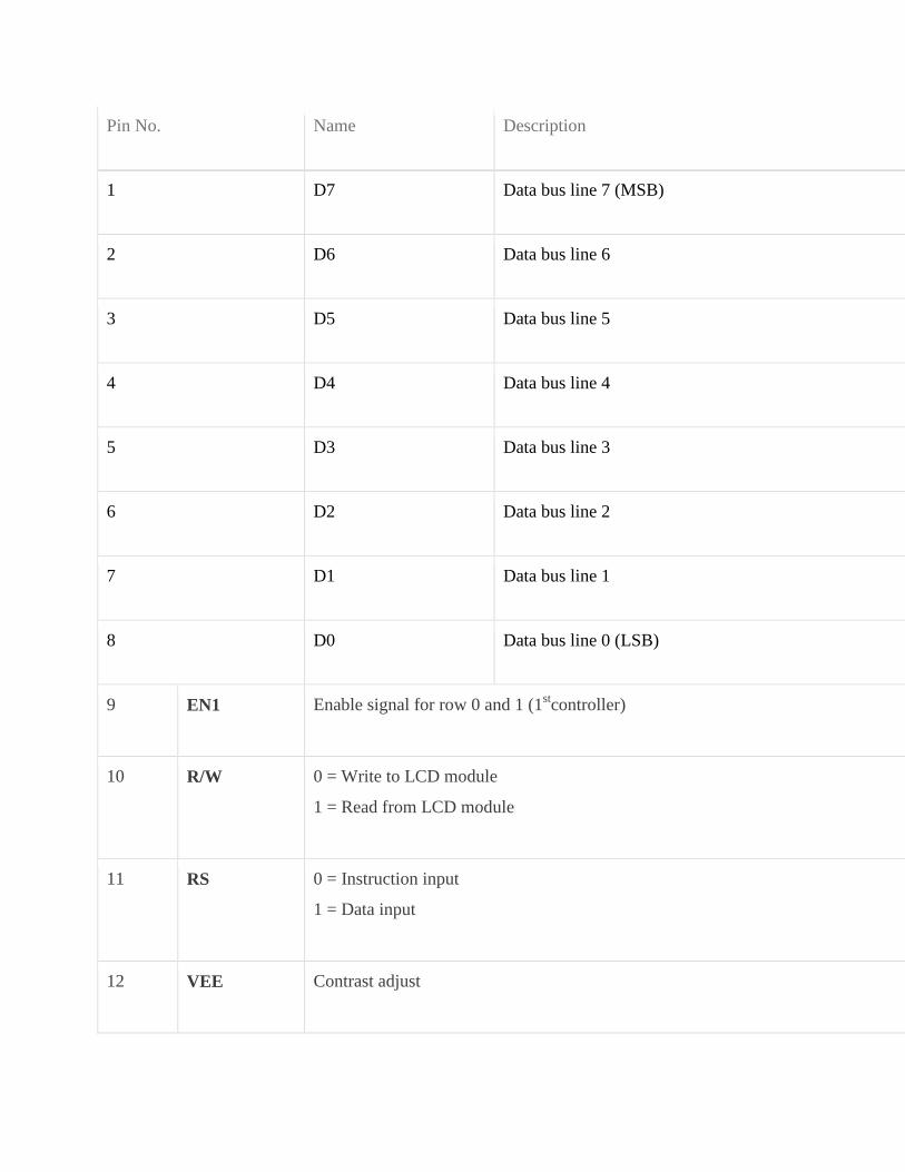
Pin No Name Description
1 D7 Data bus line 7 (MSB)
2 D6 Data bus line 6
3 D5 Data bus line 5
4 D4 Data bus line 4
5 D3 Data bus line 3
6 D2 Data bus line 2
7 D1 Data bus line 1
8 D0 Data bus line 0 (LSB)
9 EN1 Enable signal for row 0 and 1 (1stcontroller)
10 RW 0 = Write to LCD module
1 = Read from LCD module
11 RS 0 = Instruction input
1 = Data input
12 VEE Contrast adjust
Pin No Name Description
13 VSS Power supply (GND)
14 VCC Power supply (+5V)
15 EN2 Enable signal for row 2 and 3 (2nd
controller)
16 NC Not Connected
TABLE 4 - Character LCD pins with 2 Controller
[23]
85 Light-emitting diode
A light-emitting diode (LED) (pronounced) is a semiconductor light source LEDs are
used as indicator lamps in many devices and are increasingly used for lighting Introduced as a
practical electronic component in 1962 early LEDs emitted low-intensity red light but modern
versions are available across the visible ultraviolet and infrared wavelengths with very high
brightness
Fig 6-LEDS
The LED is based on the semiconductor diode When a diode is forward biased (switched
on) electrons are able to recombine with holes within the device releasing energy in the form of
photons
This effect is called electroluminescence and the color of the light (corresponding to the
energy of the photon) is determined by the energy gap of the semiconductor
An LED is usually small in area (less than 1 mm2) and integrated optical components are
used to shape its radiation pattern and assist in reflection LEDs present many advantages over
incandescent light sources including lower energy consumption longer lifetime improved
robustness smaller size faster switching and greater durability and reliability However they
are relatively expensive and require more precise current and heat management than traditional
light sources Current LED products for general lighting are more expensive to buy than
fluorescent lamp sources of comparable output
[24]
They also enjoy use in applications as diverse as replacements for traditional light
sources in aviation lighting automotive lighting (particularly indicators) and in traffic signals
The compact size of LEDs has allowed new text and video displays and sensors to be developed
while their high switching rates are useful in advanced communications technology Infrared
LEDs are also used in the remote control units of many commercial products including
televisions DVD players and other domestic appliances
86 CAPACITORS
A capacitor (formerly known as condenser) is a passive electronic component consisting
of a pair of conductors separated by a dielectric (insulator) When a potential difference (voltage)
exists across the conductors an electric field is present in the dielectric This field stores energy
and produces a mechanical force between the conductors The effect is greatest when there is a
narrow separation between large areas of conductor hence capacitor conductors are often called
plates
An ideal capacitor is characterized by a single constant value capacitance which is
measured in farads This is the ratio of the electric charge on each conductor to the potential
difference between them In practice the dielectric between the plates passes a small amount of
leakage current The conductors and leads introduce an equivalent series resistance and the
dielectric has an electric field strength limit resulting in a breakdown voltage
Capacitors are widely used in electronic circuits to block direct current while allowing
alternating current to pass to filter out interference to smooth the output of power supplies and
for many other purposes They are used in resonant circuits in radio frequency equipment to
select particular frequencies from a signal with many frequencies
[25]
Fig 7-CAPACITORS
861 Function
Capacitors store electric charge They are used with resistors in timing circuits because it
takes time for a capacitor to fill with charge They are used to smooth varying DC supplies by
acting as a reservoir of charge They are also used in filter circuits because capacitors easily pass
AC (changing) signals but they block DC (constant) signals
862 Capacitance
This is a measure of a capacitors ability to store charge A large capacitance means that
more charge can be stored Capacitance is measured in farads symbol F However 1F is very
large so prefixes are used to show the smaller values
[26]
Three prefixes (multipliers) are used micro (micro) n (nano) and p (pico)
micro means 10-6 (millionth) so 1000000microF = 1F
n means 10-9 (thousand-millionth) so 1000nF = 1microF
p means 10-12 (million-millionth) so 1000pF = 1nF
Capacitor values can be very difficult to find because there are many types of capacitor with
different labeling systems
There are many types of capacitor but they can be split into two groups polarised and
unpolarised Each group has its own circuit symbol
Polarised capacitors (large values 1microF +)
Examples
Capacitor symble
[27]
863 Electrolytic Capacitors
Electrolytic capacitors are polarised and they must be connected
the correct way round at least one of their leads will be marked + or -
They are not damaged by heat when soldering
There are two designs of electrolytic capacitors axial where the
leads are attached to each end (220microF in picture) and radial where both
leads are at the same end (10microF in picture) Radial capacitors tend to be a little smaller and they
stand upright on the circuit board
It is easy to find the value of electrolytic capacitors because they are clearly printed with
their capacitance and voltage rating The voltage rating can be quite low (6V for example) and it
should always be checked when selecting an electrolytic capacitor
If the project parts list does not specify a voltage choose a capacitor with a rating which
is greater than the projects power supply voltage 25V is a sensible minimum most battery
circuits
[28]
864 Variable capacitors
Fig 8- Variable Capacitor
Variable capacitors are mostly used in radio tuning circuits and they are sometimes called
tuning capacitors They have very small capacitance values typically between 100pF and 500pF
(100pF = 00001microF) The type illustrated usually has trimmers built in (for making small
adjustments - see below) as well as the main variable capacitor
Many variable capacitors have very short spindles which are not suitable for the standard
knobs used for variable resistors and rotary switches It would be wise to check that a suitable
knob is available before ordering a variable capacitor
Variable capacitors are not normally used in timing circuits because their capacitance is
too small to be practical and the range of values available is very limited Instead timing circuits
use a fixed capacitor and a variable resistor if it is necessary to vary the time period
[29]
865 Trimmer capacitors
Fig 9-Trimmer Capacitor Symbol
Trimmer capacitors (trimmers) are miniature variable capacitorsThey are
designed to be mounted directly onto the circuit board and adjusted only when the circuit is built
A small screwdriver or similar tool is required to adjust trimmers
The process of adjusting them requires patience because the presence of your hand and
the tool will slightly change the capacitance of the circuit in the region of the trimmer
Trimmer capacitors are only available with very small capacitances normally less than
100pF It is impossible to reduce their capacitance to zero so they are usually specified by their
minimum and maximum values for example 2-10Pf are the capacitor equivalent of presets
which are miniature variable resistors
[30]
87 RESISTORS
A resistor is a two-terminal electronic component that produces a voltage across its
terminals that is proportional to the electric current passing through it in accordance with Ohms
law
V = IR
Resistors are elements of electrical networks and electronic circuits and are ubiquitous in
most electronic equipment Practical resistors can be made of various compounds and films as
well as resistance wire (wire made of a high-resistivity alloy such as nickelchrome)
The primary characteristics of a resistor are the resistance the tolerance maximum
working voltage and the power rating Other characteristics include temperature coefficient
noise and inductance Less well-known is critical resistance the value below which power
dissipation limits the maximum permitted current flow and above which the limit is applied
voltage Critical resistance is determined by the design materials and dimensions of the resistor
Resistors can be integrated into hybrid and printed circuits as well as integrated circuits
Size and position of leads (or terminals) are relevant to equipment designers resistors must be
physically large enough not to overheat when dissipating their power
[31]
Fig 10- RESISTORS
871 Units
The ohm (symbol Ω) is the SI unit of electrical resistance named after Georg Simon Ohm
Commonly used multiples and submultiples in electrical and electronic usage are the milliohm
(1x10minus3) kilohm (1x10³) and megohm (1x10⁶)
872 Theory of operation
Ohms law-
The behavior of an ideal resistor is dictated by the relationship specified in Ohms law
Ohms law states that the voltage (V) across a resistor is proportional to the current (I)
through it where the constant of proportionality is the resistance (R)
[32]
Equivalently Ohms law can be stated
This formulation of Ohms law states that when a voltage (V) is maintained across a
resistance (R) a current (I) will flow through the resistance
This formulation is often used in practice For example if V is 12 volts and R is 400
ohms a current of 12 400 = 003 amperes will flow through the resistance R
Fixed and Variable Resistors
There are two kinds of resistors FIXED and VARIABLE The fixed resistor will have
one value and will never change (other than through temperature age etc) The resistors shown
in A and B of figure 1-29are classed as fixed resistors
The tapped resistor illustrated in B has several fixed taps and makes more than one
resistance value available The sliding contact resistor shown in C has an adjustable collar that
can be moved to tap off any resistance within the ohmic value range of the resistor
There are two types of variable resistors one called a POTENTIOMETER and the other
a RHEOSTAT (see views D and E of fig 1-29)An example of the potentiometer is the volume
control on your radio and an example of the rheostat is the dimmer control for the dash lights in
an automobile
There is a slight difference between them Rheostats usually have two connections one
fixed and the other moveable Any variable resistor can properly be called a rheostat The
potentiometer always has three connections two fixed and one moveable Generally the rheostat
has a limited range of values and A high current-handling capability
[33]
The potentiometer has a wide range of values but it usually has a limited current-
handling capability Potentiometers are always connected as voltage dividers
Fig 11-VARIABLE RESISTORS
These are miniature versions of the standard variable resistor They are designed to be
mounted directly onto the circuit board and adjusted only when the circuit is built For example
to set the frequency of an alarm tone or the sensitivity of a light-sensitive circuit
A small screwdriver or similar tool is required to adjust presets Presets are much
cheaper than standard variable resistors so they are sometimes used in projects where a standard
variable resistor would normally be used Multi turn presets are used where very precise
adjustments must be made The screw must be turned many times (10+) to move the slider from
one end of the track to the other giving very fine control
[34]
88 TRANSFORMER
881 INTRODUCTION
A transformer is a device that transfers electrical energy from one circuit to another
through inductively coupled conductorsmdashthe transformers coils A varying current in the first or
primary winding creates a varying magnetic flux in the transformers core and thus a varying
magnetic field through the secondary winding This varying magnetic field induces a varying
electromotive force (EMF) or voltage in the secondary winding This effect is called mutual
induction
If a load is connected to the secondary an electric current will flow in the secondary
winding and electrical energy will be transferred from the primary circuit through the
transformer to the load In an ideal transformer the induced voltage in the secondary winding
(VS) is in proportion to the primary voltage (VP) and is given by the ratio of the number of turns
in the secondary (NS) to the number of turns in the primary (NP) as follows
By appropriate selection of the ratio of turns a transformer thus allows an alternating
current (AC) voltage to be stepped up by making NS greater than NP or stepped down by
making NS less than NP In the vast majority of transformers the windings are coils wound
around a ferromagnetic core air-core transformers being a notable exception
Transformers range in size from a thumbnail-sized coupling transformer hidden inside a
stage microphone to huge units weighing hundreds of tons used to interconnect portions of
power grids All operate with the same basic principles although the range of designs is wide
While new technologies have eliminated the need for transformers in some electronic circuits
transformers are still found in nearly all electronic devices designed for household (mains)
voltage Transformers are essential for high voltage power transmission which makes long
distance transmission economically practical
[35]
882 Basic principles
The transformer is based on two principles firstly that an electric current can produce a
magnetic field (electromagnetism) and secondly that a changing magnetic field within a coil of
wire induces a voltage across the ends of the coil (electromagnetic induction)
Changing the current in the primary coil changes the magnetic flux that is developed The
changing magnetic flux induces a voltage in the secondary coil
Fig 12- TRANSFORMER
883 An ideal transformer
An ideal transformer is shown in the adjacent figure Current passing through the primary
coil creates a magnetic field The primary and secondary coils are wrapped around a core of very
high magnetic permeability such as iron so that most of the magnetic flux passes through both
the primary and secondary coils
884 Induction law
The voltage induced across the secondary coil may be calculated from Faradays law of
induction which states that
[36]
where VS is the instantaneous voltage NS is the number of turns in the secondary coil
and Φ equals the magnetic flux through one turn of the coil If the turns of the coil are oriented
perpendicular to the magnetic field lines the flux is the product of the magnetic flux density B
and the area A through which it cuts
The area is constant being equal to the cross-sectional area of the transformer core
whereas the magnetic field varies with time according to the excitation of the primary Since the
same magnetic flux passes through both the primary and secondary coils in an ideal transformer
the instantaneous voltage across the primary winding equals
Taking the ratio of the two equations for VS and VP gives the basic equation for
stepping up or stepping down the voltage
885 Ideal power equation
The ideal transformer as a circuit element
[37]
If the secondary coil is attached to a load that allows current to flow electrical power is
transmitted from the primary circuit to the secondary circuit Ideally the transformer is perfectly
efficient all the incoming energy is transformed from the primary circuit to the magnetic field
and into the secondary circuit If this condition is met the incoming electric power must equal
the outgoing power
P incoming = IPVP = P outgoing = ISVS
giving the ideal transformer equation
Transformers normally have high efficiency so this formula is a reasonable approximation
If the voltage is increased then the current is decreased by the same factor The
impedance in one circuit is transformed by the square of the turnrsquos ratio For example if an
impedance ZS is attached across the terminals of the secondary coil it appears to the primary
circuit to have an impedance of This relationship is reciprocal so that the impedance ZP
of the primary circuit appears to the secondary to be
886 Operation of transformers
The simplified description above neglects several practical factors in particular the
primary current required to establish a magnetic field in the core and the contribution to the field
due to current in the secondary circuit
Models of an ideal transformer typically assume a core of negligible reluctance with two
windings of zero resistance When a voltage is applied to the primary winding a small current
flows driving flux around the magnetic circuit of the core
[38]
The current required to create the flux is termed the magnetizing current since the ideal
core has been assumed to have near-zero reluctance the magnetizing current is negligible
although still required to create the magnetic field
The changing magnetic field induces an electromotive force (EMF) across each winding
Since the ideal windings have no impedance they have no associated voltage drop and so the
voltages VP and VS measured at the terminals of the transformer are equal to the corresponding
EMFs
The primary EMF acting as it does in opposition to the primary voltage is sometimes
termed the back EMF This is due to Lenzs law which states that the induction of EMF would
always be such that it will oppose development of any such change in magnetic field
887 Practical considerations
Leakage flux
The ideal transformer model assumes that all flux generated by the primary winding links
all the turns of every winding including itself In practice some flux traverses paths that take it
outside the windings
Such flux is termed leakage flux and results in leakage inductance in series with the
mutually coupled transformer windings
[39]
Leakage results in energy being alternately stored in and discharged from the magnetic
fields with each cycle of the power supply
It is not directly a power loss (see Stray losses below) but results in inferior voltage
regulation causing the secondary voltage to fail to be directly proportional to the primary
particularly under heavy load Transformers are therefore normally designed to have very low
leakage inductance
However in some applications leakage can be a desirable property and long magnetic
paths air gaps or magnetic bypass shunts may be deliberately introduced to a transformers
design to limit the short-circuit current it will supply Leaky transformers may be used to supply
loads that exhibit negative resistance such as electric arcs mercury vapor lamps and neon signs
or for safely handling loads that become periodically short-circuited such as electric arc welders
Air gaps are also used to keep a transformer from saturating especially audio-frequency
transformers in circuits that have a direct current flowing through the windings Leakage
inductance is also helpful when transformers are operated in parallel
It can be shown that if the per-unit inductance of two transformers is the same (a
typical value is 5) they will automatically split power correctly (eg 500 KVA units in
parallel with 1000 KVA unit the larger one will carry twice the current)
888 Voltage transformers
Voltage transformers (VTs) or potential transformers (PTs) are another type of
instrument transformer used for metering and protection in high-voltage circuits They are
designed to present negligible load to the supply being measured and to have a precise voltage
ratio to accurately step down high voltages so that metering and protective relay equipment can
be operated at a lower potential
[40]
Typically the secondary of a voltage transformer is rated for 69 or 120 Volts at rated
primary voltage to match the input ratings of protection relays
Fig 13- VOLTAGE TRANSFORMER
The transformer winding high-voltage connection points are typically labeled as H1 H2
(sometimes H0 if it is internally grounded) and X1 X2 and sometimes an X3 tap may be
present Sometimes a second isolated winding (Y1 Y2 Y3) may also be available on the same
voltage transformer The high side (primary) may be connected phase to ground or phase to
phase The low side (secondary) is usually phase to ground
The terminal identifications (H1 X1 Y1 etc) are often referred to as polarity This
applies to current transformers as well At any instant terminals with the same suffix numeral
have the same polarity and phase Correct identification of terminals and wiring is essential for
proper operation of metering and protection relays
[41]
While VTs were formerly used for all voltages greater than 240V primary modern
meters eliminate the need VTs for most secondary service voltages VTs are typically used in
circuits where the system voltage level is above 600 V Modern meters eliminate the need of
VTs since the voltage remains constant and it is measured in the incoming supply
Transformer + Rectifier
The varying DC output is suitable for lamps heaters and standard motors It is not
suitable for electronic circuits unless they include a smoothing capacitor Types
Auto transformer Poly-phase transformers Leakage transformers resonant transformers
Audio transformers Instrument transformers
89 VOLTAGE REGULATOR-
A voltage regulator is designed to automatically maintain a constant voltage level A
voltage regulator may be a simple feed-forward design or may include negative
feedback control loops
[42]
It may use an electromechanical mechanism or electronic components Depending on
the design it may be used to regulate one or more AC or DC voltages
Electronic voltage regulators are found in devices such as computer power supplies where
they stabilize the DC voltages used by the processor and other elements In
automobile alternators and central power station generator plants voltage regulators control the
output of the plant In an electric power distribution system voltage regulators may be installed
at a substation or along distribution lines so that all customers receive steady voltage independent
of how much power is drawn from the line
891 MEASURES OF REGULATOR QUANTITY-
load regulation is the change in output voltage for a given change in load current (for
example typically 15 mV maximum 100 mV for load currents between 5 mA and 14 A at
some specified temperature and input voltage)
line regulation or input regulation is the degree to which output voltage changes with input
(supply) voltage changes - as a ratio of output to input change (for example typically
13 mVV) or the output voltage change over the entire specified input voltage range (for
example plus or minus 2 for input voltages between 90 V and 260 V 50-60 Hz)
Other important parameters are
Temperature coefficient of the output voltage is the change with temperature (perhaps
averaged over a given temperature range)
[43]
Initial accuracy of a voltage regulator (or simply the voltage accuracy) reflects the error in
output voltage for a fixed regulator without taking into account temperature or aging effects
on output accuracy
Dropout voltage is the minimum difference between input voltage and output voltage for
which the regulator can still supply the specified current A low drop-out (LDO) regulator is
designed to work well even with an input supply of only a volt or so above the output
voltage The input-output differential at which the voltage regulator will no longer maintain
regulation is the dropout voltage Further reduction in input voltage will result in reduced
output voltage This value is dependent on load current and junction temperature
Absolute maximum ratings are defined for regulator components specifying the continuous
and peak output currents that may be used (sometimes internally limited) the maximum
input voltage maximum power dissipation at a given temperature etc
Output noise (thermal white noise) and output dynamic impedance may be specified as
graphs versus frequency while output ripple noise (mains hum or switch-mode hash
noise) may be given as peak-to-peak or RMS voltages or in terms of their spectra
[44]
Quiescent current in a regulator circuit is the current drawn internally not available to the
load normally measured as the input current while no load is connected (and hence a source
of inefficiency some linear regulators are surprisingly more efficient at very low current
loads than switch-mode designs because of this)
Transient response is the reaction of a regulator when a (sudden) change of the load current
(called the load transient) or input voltage (called the line transient) occurs Some regulators
will tend to oscillate or have a slow response time which in some cases might lead to
undesired results This value is different from the regulation parameters as that is the stable
situation definition The transient response shows the behaviour of the regulator on a change
This data is usually provided in the technical documentation of a regulator and is also
dependent on output capacitance
Mirror-image insertion protection means that a regulator is designed for use when a voltage
usually not higher than the maximum input voltage of the regulator is applied to its output
pin while its input terminal is at a low voltage volt-free or grounded Some regulators can
continuously withstand this situation others might only manage it for a limited time such as
60 seconds as usually specified in the datasheet This situation can occur when a three
terminal regulator is incorrectly mounted for example on a PCB with the output terminal
connected to the unregulated DC input and the input connected to the load Mirror-image
insertion protection is also important when a regulator circuit is used in battery charging
circuits when external power fails or is not turned on and the output terminal remains at
battery voltage
[45]
892 ELECTRONIC VOLTAGE REGULATOR-
A simple voltage regulator can be made from a resistor in series with a diode (or series of
diodes) Due to the logarithmic shape of diode V-I curves the voltage across the diode changes
only slightly due to changes in current drawn or changes in the input When precise voltage
control and efficiency are not important this design may work fine
Feedback voltage regulators operate by comparing the actual output voltage to some
fixed reference voltage Any difference is amplified and used to control the regulation element in
such a way as to reduce the voltage error This forms a negative feedback control loop
increasing the open-loop gain tends to increase regulation accuracy but reduce stability
(Stability is avoidance of oscillation or ringing during step changes) There will also be a trade-
off between stability and the speed of the response to changes If the output voltage is too low
(perhaps due to input voltage reducing or load current increasing) the regulation element is
commanded up to a point to produce a higher output voltagendashby dropping less of the input
voltage (for linear series regulators and buck switching regulators) or to draw input current for
longer periods (boost-type switching regulators) if the output voltage is too high the regulation
element will normally be commanded to produce a lower voltage However many regulators
have over-current protection so that they will entirely stop sourcing current (or limit the current
in some way) if the output current is too high and some regulators may also shut down if the
input voltage is outside a given range (see also crowbar circuits)
[46]
893 ELECTRO MECHANICAL REGULATORS-
Fig 14- Circuit design for a simple electromechanical voltage regulator
Fig 15-A voltage stabilizer using electromechanical relays for switching
Fig 16-Graph of voltage output on a time scale
[47]
In electromechanical regulators voltage regulation is easily accomplished by coiling the
sensing wire to make an electromagnet The magnetic field produced by the current attracts a
moving ferrous core held back under spring tension or gravitational pull As voltage increases so
does the current strengthening the magnetic field produced by the coil and pulling the core
towards the field The magnet is physically connected to a mechanical power switch which
opens as the magnet moves into the field As voltage decreases so does the current releasing
spring tension or the weight of the core and causing it to retract This closes the switch and
allows the power to flow once more
If the mechanical regulator design is sensitive to small voltage fluctuations the motion of
the solenoid core can be used to move a selector switch across a range of resistances or
transformer windings to gradually step the output voltage up or down or to rotate the position of
a moving-coil AC regulator
Early automobile generators and alternators had a mechanical voltage regulator using
one two or three relays and variousresistors to stabilize the generators output at slightly more
than 6 or 12 V independent of the engines rpm or the varying load on the vehicles electrical
system Essentially the relay(s) employed pulse width modulation to regulate the output of the
generator controlling the field current reaching the generator (or alternator) and in this way
controlling the output voltage produced
The regulators used for DC generators (but not alternators) also disconnect the generator
when it was not producing electricity thereby preventing the battery from discharging back into
the generator and attempting to run it as a motor The rectifier diodes in an alternator
automatically perform this function so that a specific relay is not required this appreciably
simplified the regulator design
More modern designs now use solid state technology (transistors) to perform the same
function that the relays perform in electromechanical regulators
[48]
Electromechanical regulators are used for mains voltage stabilisation mdash see AC voltage
stabilizers below
894 AUTOMATIC VOLTAGE REGULATOR-
Fig 17-Voltage regulator for generators
To control the output of generators (as seen in ships and power stations or on oil rigs
greenhouses and emergency power systems) automatic voltage regulators are used This is an
active system While the basic principle is the same the system itself is more complex An
automatic voltage regulator (or AVR for short) consist of several components such as diodes
capacitors resistors and potentiometers or even microcontrollers all placed on a circuit board
This is then mounted near the generator and connected with several wires to measure and adjust
the generator
How an AVR works In the first place the AVR monitors the output voltage and controls
the input voltage for the exciter of the generator By increasing or decreasing the generator
control voltage the output voltage of the generator increases or decreases accordingly
[49]
The AVR calculates how much voltage has to be sent to the exciter numerous times a
second therefore stabilizing the output voltage to a predetermined setpoint When two or more
generators are powering the same system (parallel operation) the AVR receives information from
more generators to match all output
9 SOFTWARE-
The lsquoInit_EEPROMrsquo and lsquoSpeedorsquo source codes of this project are written in Assembly
language These are compiled using an open-source ASEM-51 assembler to generate the
Init_EEPROMhex and Speedohex files The hex files are burnt into the microcontroller chip
Two internal timers of the microcontroller are configured as 8-bit counters to count the number
of pulses generated by the speed sensor One timer is used to measure the distance and the other
for speed calculation A software delay of one second is generated after the speed counter is
triggered The speed count value is obtained from the counter registers To speed up the process
a look-up data table is stored in the ROM that helps the microcontroller to convert the number of
pulses into the corresponding speed values
The program flow-chart is shown in Fig 2 The lsquodistancersquo counter is incremented every
100 metres The wheel has to make 53 revolutions to achieve this The distance counter is loaded
with an initial value of 203 (255-53+1) and is incremented on each revolution After 53 counts
the timer overflows and generates an interrupt to notify the microcontroller that 100 metres are
covered In the interrupt service routine the microcontroller updates the corresponding lsquoDS1rsquo
distance variable Instead of saving distance variables after each cycle the microcontroller saves
these readings when the vehicle is at halt (speed is 000 kmhour) In other words when the
vehicle is stopped at traffic signals or before the ignition key is turned off the last reading is
saved to the EEPROM The same reading again retrieved from the EEPROM when the bike is
turned on next time and the readings are updated for each trip
[50]
91 Program can be used-
includeat89x52h
includelcdh
includelt24cxxcgt
unsigned char val=0x00
unsigned int distance=0speed=0cal=0
unsigned char km=0t=0
void timer0(void) interrupt 1
t++
distance=distance+100
if(distance==1000)
km=km+1
t=0
distance=0
[51]
void one_sec()
unsigned int ij
for(i=0ilt120i++)
for(j=0jlt1271j++)
void display(int num)
unsigned char tuf
t=num10
num=num10
[52]
u=num10
num=num10
f=num10
lcd_data(0+f)
lcd_data(0+u)
lcd_data(0+t)
void bintoascii(unsigned char value)
unsigned char xd1d2d3abc
x=value10
d1=value10
d2=x10
d3=x10
a=0x30|d1
b=0x30|d2
c=0x30|d3
lcd_data( )
[53]
lcd_data(c)
lcd_data(b)
lcd_data(a)
lcd_com(0xc0)
lcd_puts(KM )
display(km)
lcd_puts( MT )
display(distance)
void main()
unsigned char c=0d=0
T1=1
T0=1
TMOD=0x66
TH0=206
TL0=206
TH1=0
[54]
TL1=0
TR0=1
P1=0xFF
IE=0x82
RW24XX(ampc 1 1 0xA1 M2404)
RW24XX(ampd 1 4 0xA1 M2404)
t=d
km=c
distance=t100
c=0d=0
lcd_init()
lcd_com(0x01)
lcd_com(0x0C)
lcd_com(0x80)
while(1)
TR0=1
val=TL0
[55]
TL1=0
TR1=1
one_sec()
speed=TL1
TR1=0
cal=(speed7)
lcd_com(0x80)
lcd_puts(Speed )
display(cal)
lcd_com(0x89)
lcd_data( )
bintoascii(val)
if(speed==0)
c=km
d=t
RW24XX(ampc 1 1 0xA0 M2404)
RW24XX(ampd 1 4 0xA0 M2404)
[56]
if(P1_4==0)
while(P1_4=1)
c=0
RW24XX(ampc 2 1 0xA0 M2404)
[57]
Fig 18- Flow Chart
[58]
10 CONSTRUCTION-
The reed switch and a magnet need to be fixed on the front wheel of the motor bike
(Hero Hondarsquos Splendor)
A small circular magnet(about 2 cm in diametre) normally used in speakers of small
toys can be used Fix the magnet to the cen- tral drum of the wheel just below the spokes
connected to the drum Secure the magnet using hot glue or Araldite For fixing the reed switch
a PVC pipe contraption needs to be made so that the magnet and reed switch are aligned as
shown in Fig 3 The materials required to build the con- traption are shown in Fig 4 Cut a
32cm diameter PVC pipe measuring 152 cm in length perpendicularly into two halves Use
only one half of the PVC pipe Mount and secure the reed switch using Araldite and cable ties on
the plastic handle (normally used in emergency lights) Once it dries up solder two wires to the
two opposite end leads of the reed switch Fix the plastic handle on the half cut PVC pipe using
screws Now place the pipe on the front shock-absorber fork such that reed switch faces to-
wards the magnet Connect a multimeter set in continuity mode to the two wires coming from
the reed switch Rotate the wheel slowly and see whether the reed switch closes when the magnet
passes across it If it does the multimeter will give a continuity beep
When the magnet moves away from the reed switch the beep will stop indicating that
the reed switch is open Make a few trials to find the optimal position for mounting and fixing
the PVC pipe such that the reed switch works smoothly Mark the location on the front shock-ab-
sorber fork
Now you can fix the PVC pipe contraption to the shock-ab- sorber fork us- ing hot glue
as shown in Fig 5 Use liberal amount of hot glue to secure it to the pipe Care- fully route the
two wires up to the bikersquos handle bar using cable ties to secure the wire This com- pletes the
sensor mounting part The main cir- cuit and the LCD module can be housed in suit- able plastic
en- closures which are readily avail- able in electronic projects shops
[59]
These enclosures should have precut slot for easy mounting of the LCD pan- el If such
boxes are not available you can use the plastic boxes of electronic chokes by suitably re- moving
some portions for the LCD panel Power sup- ply can be taken either directly from the bikersquos
12V battery or tapped from the console which houses horn head- light and indicator light
switches For this you need to remove the switch console and identify positive wire and ground
wire using a mul- timeter When carrying out this step remember to turn the ignition key to lsquoonrsquo
position Solder a 60cm two-core wire to the positive and negative terminals inside the switch
console The advantage of taking supply from the switch console is that the ignition key controls
the power supply to the main unit without having a separate on-off switch An actual-size
single-side PCB layout of the microcontroller-based speedometer-cum-odometer is shown in Fig
16 and its component layout in Fig 17
Fig 19-Component layout for PCB
11 TESTING-
After all the components are soldered on the PCB program the microcon- troller with
Init_EEPROMhex file and place the microcontroller in a 20-pin IC base and switch on the
circuit In the first line of the LCD lsquoINIT_EEPROMrsquo appears After five seconds lsquo000000rsquo is
displayed in the second line This process erases any previous data and sets the initial readings in
the EEPROM to zero Now switch off the supply and program the microcontroller with
lsquospeedohexrsquo main file After pro- gramming place the microcontroller back in the circuit and
switch on the supply The LCD will show lsquoKms 000000rsquo in the first line and lsquoSpeed- KmsHr
000rsquo in the second line Now the unit is ready to mount on your bike Connect the two wires
coming from the reed switch and the power supply wires to the main unit Mount the unit at the
centre of the bikersquos handle bar on top of the lsquoUrsquo clamps that secure the handle bar to the chassis
You can use cable ties to accomplish this Mounting arrange- ment of the unit is shown in Fig 6
Now start the bike take a test ride and if connections are correct the speed and the distance will
be displayed on the LCD
[61]
A protective cover like polythene can be used for the main unit on rainy days EFY note
The source codes for this article have been included in this monthrsquos EFY-CD
111 Calculations-
You first need to know the radius of the bikersquos front wheel The calculations here are
based on Hero Hondarsquos Splendor model The radius of the front wheel is 30 cm (This can vary
with the
brand or model) Circumference of the wheel= 2πr (where lsquorrsquo is in cm) = 2times314times30 = 1884 cm
or 1884 meters
1111 Speed-
Letrsquos assume that in 1 second the wheel completes one revolution In other words in one
second the bike has covered 188 metres Therefore the speed in kmhour Ntimes188times36001000 =
Ntimes6784 or Ntimes68 where lsquoNrsquo is the number of revolutions per second lsquo68rsquo is a constant and
only lsquoNrsquo varies for example if lsquoNrsquo is 5 the speed equals 5x68= 34 kmhour
1112 Distance-
The odometer is updated every 100 metres To cover 100 metres the wheel is required to
make approximately 53 revolutions (100188) The microcontroller takes care of the tasks of
revolutions counting speed calculation conversion and display of results
[62]
12 FEATURES-
[1] Digital read out
[2] Speed displayed in kmhr
[3] Distance travelled displayed in km
[4] Readings saved in non volatile memory
[5] Realibility due to use of the microcontroller
[6] No mechanical wear amp tear
[7] Home-brewed speed transducer or sensor
[8] Self reset to zero after completion of 999999km
[9] Easy to built amp fix on the bike
[63]
13 APPLICATION-
[1] It is in luxury cars and motor bike
[2] It is used to measured speed of the motor bike
[3] It measures speed amp quantity of fuel
[4] It is used to counting revolution and speed calculation of cars
[5] It is for conversion of speed and display results
Fig 20- APPLICATION
[64]
14 CONCLUSION-
Considering the total requirement and need of society as well as according to cost
analysis and project profitability statement it is concluded that the project Microcontroller based
speedometer-cum-odometer is technically viable financially feasible and suitable for speed
measurement
[65]
15REFERENCES
[1] B Ravindranath M Chander Power System Protection and Switchgear NEW AGE
INTERNATIONAL PUBLISHERS 2nd
edition 2011 pp31-39148-153255-385
[2] A Chakrabarti M L Soni A Text Book ON POWER SYSTEM ENGINEERING
Dhanpat Rai amp CO 2nd
edition 2010 pp539-578579-616617-632
[3] B L Theraja A K Theraja A Text Book ON ELECTRICAL MACHINES S CHAND
PUBLICATION 1st edition 2005 pp1243-1312
[4] Ashfaq Hussain ELECTRICAL MACHINES DHANPAT RAI ampCO 2nd
edition
2005pp307-416
[5] V K Mehta Rohit Mehta Principles of ELECTRICAL MACHINES S CHAND
PUBLICATION 1st edition 2002 pp313-377
[6] J B Gupta THEORY amp PERFORMANCE of ELECTRICAL MACHINES S K
KATARIA amp SONS 14th
edition 2006 pp359-439
[7] Yang ES ―Fundamentals of Semiconductor Devices chap 1 McGraw Hill Book
Company New York 1978
[8] wwwgooglecom
[9] wwwieeeorg
[10] Wikipedia- httpsenwikipediaorgwikiElectronic_component
[11] All Electronics- wwwallelectronicscom
[12] wwwelectrical4ucom
[13] wwwelectricalengineeringschoolsorg
[14] EFY- httpswwwelectronicsforucom
[15] wwwelectrical-engineering-portalcom
[16] wwwrealworldengineeringorg
[66]
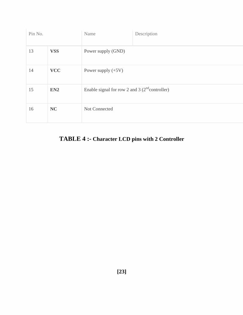
Pin No Name Description
13 VSS Power supply (GND)
14 VCC Power supply (+5V)
15 EN2 Enable signal for row 2 and 3 (2nd
controller)
16 NC Not Connected
TABLE 4 - Character LCD pins with 2 Controller
[23]
85 Light-emitting diode
A light-emitting diode (LED) (pronounced) is a semiconductor light source LEDs are
used as indicator lamps in many devices and are increasingly used for lighting Introduced as a
practical electronic component in 1962 early LEDs emitted low-intensity red light but modern
versions are available across the visible ultraviolet and infrared wavelengths with very high
brightness
Fig 6-LEDS
The LED is based on the semiconductor diode When a diode is forward biased (switched
on) electrons are able to recombine with holes within the device releasing energy in the form of
photons
This effect is called electroluminescence and the color of the light (corresponding to the
energy of the photon) is determined by the energy gap of the semiconductor
An LED is usually small in area (less than 1 mm2) and integrated optical components are
used to shape its radiation pattern and assist in reflection LEDs present many advantages over
incandescent light sources including lower energy consumption longer lifetime improved
robustness smaller size faster switching and greater durability and reliability However they
are relatively expensive and require more precise current and heat management than traditional
light sources Current LED products for general lighting are more expensive to buy than
fluorescent lamp sources of comparable output
[24]
They also enjoy use in applications as diverse as replacements for traditional light
sources in aviation lighting automotive lighting (particularly indicators) and in traffic signals
The compact size of LEDs has allowed new text and video displays and sensors to be developed
while their high switching rates are useful in advanced communications technology Infrared
LEDs are also used in the remote control units of many commercial products including
televisions DVD players and other domestic appliances
86 CAPACITORS
A capacitor (formerly known as condenser) is a passive electronic component consisting
of a pair of conductors separated by a dielectric (insulator) When a potential difference (voltage)
exists across the conductors an electric field is present in the dielectric This field stores energy
and produces a mechanical force between the conductors The effect is greatest when there is a
narrow separation between large areas of conductor hence capacitor conductors are often called
plates
An ideal capacitor is characterized by a single constant value capacitance which is
measured in farads This is the ratio of the electric charge on each conductor to the potential
difference between them In practice the dielectric between the plates passes a small amount of
leakage current The conductors and leads introduce an equivalent series resistance and the
dielectric has an electric field strength limit resulting in a breakdown voltage
Capacitors are widely used in electronic circuits to block direct current while allowing
alternating current to pass to filter out interference to smooth the output of power supplies and
for many other purposes They are used in resonant circuits in radio frequency equipment to
select particular frequencies from a signal with many frequencies
[25]
Fig 7-CAPACITORS
861 Function
Capacitors store electric charge They are used with resistors in timing circuits because it
takes time for a capacitor to fill with charge They are used to smooth varying DC supplies by
acting as a reservoir of charge They are also used in filter circuits because capacitors easily pass
AC (changing) signals but they block DC (constant) signals
862 Capacitance
This is a measure of a capacitors ability to store charge A large capacitance means that
more charge can be stored Capacitance is measured in farads symbol F However 1F is very
large so prefixes are used to show the smaller values
[26]
Three prefixes (multipliers) are used micro (micro) n (nano) and p (pico)
micro means 10-6 (millionth) so 1000000microF = 1F
n means 10-9 (thousand-millionth) so 1000nF = 1microF
p means 10-12 (million-millionth) so 1000pF = 1nF
Capacitor values can be very difficult to find because there are many types of capacitor with
different labeling systems
There are many types of capacitor but they can be split into two groups polarised and
unpolarised Each group has its own circuit symbol
Polarised capacitors (large values 1microF +)
Examples
Capacitor symble
[27]
863 Electrolytic Capacitors
Electrolytic capacitors are polarised and they must be connected
the correct way round at least one of their leads will be marked + or -
They are not damaged by heat when soldering
There are two designs of electrolytic capacitors axial where the
leads are attached to each end (220microF in picture) and radial where both
leads are at the same end (10microF in picture) Radial capacitors tend to be a little smaller and they
stand upright on the circuit board
It is easy to find the value of electrolytic capacitors because they are clearly printed with
their capacitance and voltage rating The voltage rating can be quite low (6V for example) and it
should always be checked when selecting an electrolytic capacitor
If the project parts list does not specify a voltage choose a capacitor with a rating which
is greater than the projects power supply voltage 25V is a sensible minimum most battery
circuits
[28]
864 Variable capacitors
Fig 8- Variable Capacitor
Variable capacitors are mostly used in radio tuning circuits and they are sometimes called
tuning capacitors They have very small capacitance values typically between 100pF and 500pF
(100pF = 00001microF) The type illustrated usually has trimmers built in (for making small
adjustments - see below) as well as the main variable capacitor
Many variable capacitors have very short spindles which are not suitable for the standard
knobs used for variable resistors and rotary switches It would be wise to check that a suitable
knob is available before ordering a variable capacitor
Variable capacitors are not normally used in timing circuits because their capacitance is
too small to be practical and the range of values available is very limited Instead timing circuits
use a fixed capacitor and a variable resistor if it is necessary to vary the time period
[29]
865 Trimmer capacitors
Fig 9-Trimmer Capacitor Symbol
Trimmer capacitors (trimmers) are miniature variable capacitorsThey are
designed to be mounted directly onto the circuit board and adjusted only when the circuit is built
A small screwdriver or similar tool is required to adjust trimmers
The process of adjusting them requires patience because the presence of your hand and
the tool will slightly change the capacitance of the circuit in the region of the trimmer
Trimmer capacitors are only available with very small capacitances normally less than
100pF It is impossible to reduce their capacitance to zero so they are usually specified by their
minimum and maximum values for example 2-10Pf are the capacitor equivalent of presets
which are miniature variable resistors
[30]
87 RESISTORS
A resistor is a two-terminal electronic component that produces a voltage across its
terminals that is proportional to the electric current passing through it in accordance with Ohms
law
V = IR
Resistors are elements of electrical networks and electronic circuits and are ubiquitous in
most electronic equipment Practical resistors can be made of various compounds and films as
well as resistance wire (wire made of a high-resistivity alloy such as nickelchrome)
The primary characteristics of a resistor are the resistance the tolerance maximum
working voltage and the power rating Other characteristics include temperature coefficient
noise and inductance Less well-known is critical resistance the value below which power
dissipation limits the maximum permitted current flow and above which the limit is applied
voltage Critical resistance is determined by the design materials and dimensions of the resistor
Resistors can be integrated into hybrid and printed circuits as well as integrated circuits
Size and position of leads (or terminals) are relevant to equipment designers resistors must be
physically large enough not to overheat when dissipating their power
[31]
Fig 10- RESISTORS
871 Units
The ohm (symbol Ω) is the SI unit of electrical resistance named after Georg Simon Ohm
Commonly used multiples and submultiples in electrical and electronic usage are the milliohm
(1x10minus3) kilohm (1x10³) and megohm (1x10⁶)
872 Theory of operation
Ohms law-
The behavior of an ideal resistor is dictated by the relationship specified in Ohms law
Ohms law states that the voltage (V) across a resistor is proportional to the current (I)
through it where the constant of proportionality is the resistance (R)
[32]
Equivalently Ohms law can be stated
This formulation of Ohms law states that when a voltage (V) is maintained across a
resistance (R) a current (I) will flow through the resistance
This formulation is often used in practice For example if V is 12 volts and R is 400
ohms a current of 12 400 = 003 amperes will flow through the resistance R
Fixed and Variable Resistors
There are two kinds of resistors FIXED and VARIABLE The fixed resistor will have
one value and will never change (other than through temperature age etc) The resistors shown
in A and B of figure 1-29are classed as fixed resistors
The tapped resistor illustrated in B has several fixed taps and makes more than one
resistance value available The sliding contact resistor shown in C has an adjustable collar that
can be moved to tap off any resistance within the ohmic value range of the resistor
There are two types of variable resistors one called a POTENTIOMETER and the other
a RHEOSTAT (see views D and E of fig 1-29)An example of the potentiometer is the volume
control on your radio and an example of the rheostat is the dimmer control for the dash lights in
an automobile
There is a slight difference between them Rheostats usually have two connections one
fixed and the other moveable Any variable resistor can properly be called a rheostat The
potentiometer always has three connections two fixed and one moveable Generally the rheostat
has a limited range of values and A high current-handling capability
[33]
The potentiometer has a wide range of values but it usually has a limited current-
handling capability Potentiometers are always connected as voltage dividers
Fig 11-VARIABLE RESISTORS
These are miniature versions of the standard variable resistor They are designed to be
mounted directly onto the circuit board and adjusted only when the circuit is built For example
to set the frequency of an alarm tone or the sensitivity of a light-sensitive circuit
A small screwdriver or similar tool is required to adjust presets Presets are much
cheaper than standard variable resistors so they are sometimes used in projects where a standard
variable resistor would normally be used Multi turn presets are used where very precise
adjustments must be made The screw must be turned many times (10+) to move the slider from
one end of the track to the other giving very fine control
[34]
88 TRANSFORMER
881 INTRODUCTION
A transformer is a device that transfers electrical energy from one circuit to another
through inductively coupled conductorsmdashthe transformers coils A varying current in the first or
primary winding creates a varying magnetic flux in the transformers core and thus a varying
magnetic field through the secondary winding This varying magnetic field induces a varying
electromotive force (EMF) or voltage in the secondary winding This effect is called mutual
induction
If a load is connected to the secondary an electric current will flow in the secondary
winding and electrical energy will be transferred from the primary circuit through the
transformer to the load In an ideal transformer the induced voltage in the secondary winding
(VS) is in proportion to the primary voltage (VP) and is given by the ratio of the number of turns
in the secondary (NS) to the number of turns in the primary (NP) as follows
By appropriate selection of the ratio of turns a transformer thus allows an alternating
current (AC) voltage to be stepped up by making NS greater than NP or stepped down by
making NS less than NP In the vast majority of transformers the windings are coils wound
around a ferromagnetic core air-core transformers being a notable exception
Transformers range in size from a thumbnail-sized coupling transformer hidden inside a
stage microphone to huge units weighing hundreds of tons used to interconnect portions of
power grids All operate with the same basic principles although the range of designs is wide
While new technologies have eliminated the need for transformers in some electronic circuits
transformers are still found in nearly all electronic devices designed for household (mains)
voltage Transformers are essential for high voltage power transmission which makes long
distance transmission economically practical
[35]
882 Basic principles
The transformer is based on two principles firstly that an electric current can produce a
magnetic field (electromagnetism) and secondly that a changing magnetic field within a coil of
wire induces a voltage across the ends of the coil (electromagnetic induction)
Changing the current in the primary coil changes the magnetic flux that is developed The
changing magnetic flux induces a voltage in the secondary coil
Fig 12- TRANSFORMER
883 An ideal transformer
An ideal transformer is shown in the adjacent figure Current passing through the primary
coil creates a magnetic field The primary and secondary coils are wrapped around a core of very
high magnetic permeability such as iron so that most of the magnetic flux passes through both
the primary and secondary coils
884 Induction law
The voltage induced across the secondary coil may be calculated from Faradays law of
induction which states that
[36]
where VS is the instantaneous voltage NS is the number of turns in the secondary coil
and Φ equals the magnetic flux through one turn of the coil If the turns of the coil are oriented
perpendicular to the magnetic field lines the flux is the product of the magnetic flux density B
and the area A through which it cuts
The area is constant being equal to the cross-sectional area of the transformer core
whereas the magnetic field varies with time according to the excitation of the primary Since the
same magnetic flux passes through both the primary and secondary coils in an ideal transformer
the instantaneous voltage across the primary winding equals
Taking the ratio of the two equations for VS and VP gives the basic equation for
stepping up or stepping down the voltage
885 Ideal power equation
The ideal transformer as a circuit element
[37]
If the secondary coil is attached to a load that allows current to flow electrical power is
transmitted from the primary circuit to the secondary circuit Ideally the transformer is perfectly
efficient all the incoming energy is transformed from the primary circuit to the magnetic field
and into the secondary circuit If this condition is met the incoming electric power must equal
the outgoing power
P incoming = IPVP = P outgoing = ISVS
giving the ideal transformer equation
Transformers normally have high efficiency so this formula is a reasonable approximation
If the voltage is increased then the current is decreased by the same factor The
impedance in one circuit is transformed by the square of the turnrsquos ratio For example if an
impedance ZS is attached across the terminals of the secondary coil it appears to the primary
circuit to have an impedance of This relationship is reciprocal so that the impedance ZP
of the primary circuit appears to the secondary to be
886 Operation of transformers
The simplified description above neglects several practical factors in particular the
primary current required to establish a magnetic field in the core and the contribution to the field
due to current in the secondary circuit
Models of an ideal transformer typically assume a core of negligible reluctance with two
windings of zero resistance When a voltage is applied to the primary winding a small current
flows driving flux around the magnetic circuit of the core
[38]
The current required to create the flux is termed the magnetizing current since the ideal
core has been assumed to have near-zero reluctance the magnetizing current is negligible
although still required to create the magnetic field
The changing magnetic field induces an electromotive force (EMF) across each winding
Since the ideal windings have no impedance they have no associated voltage drop and so the
voltages VP and VS measured at the terminals of the transformer are equal to the corresponding
EMFs
The primary EMF acting as it does in opposition to the primary voltage is sometimes
termed the back EMF This is due to Lenzs law which states that the induction of EMF would
always be such that it will oppose development of any such change in magnetic field
887 Practical considerations
Leakage flux
The ideal transformer model assumes that all flux generated by the primary winding links
all the turns of every winding including itself In practice some flux traverses paths that take it
outside the windings
Such flux is termed leakage flux and results in leakage inductance in series with the
mutually coupled transformer windings
[39]
Leakage results in energy being alternately stored in and discharged from the magnetic
fields with each cycle of the power supply
It is not directly a power loss (see Stray losses below) but results in inferior voltage
regulation causing the secondary voltage to fail to be directly proportional to the primary
particularly under heavy load Transformers are therefore normally designed to have very low
leakage inductance
However in some applications leakage can be a desirable property and long magnetic
paths air gaps or magnetic bypass shunts may be deliberately introduced to a transformers
design to limit the short-circuit current it will supply Leaky transformers may be used to supply
loads that exhibit negative resistance such as electric arcs mercury vapor lamps and neon signs
or for safely handling loads that become periodically short-circuited such as electric arc welders
Air gaps are also used to keep a transformer from saturating especially audio-frequency
transformers in circuits that have a direct current flowing through the windings Leakage
inductance is also helpful when transformers are operated in parallel
It can be shown that if the per-unit inductance of two transformers is the same (a
typical value is 5) they will automatically split power correctly (eg 500 KVA units in
parallel with 1000 KVA unit the larger one will carry twice the current)
888 Voltage transformers
Voltage transformers (VTs) or potential transformers (PTs) are another type of
instrument transformer used for metering and protection in high-voltage circuits They are
designed to present negligible load to the supply being measured and to have a precise voltage
ratio to accurately step down high voltages so that metering and protective relay equipment can
be operated at a lower potential
[40]
Typically the secondary of a voltage transformer is rated for 69 or 120 Volts at rated
primary voltage to match the input ratings of protection relays
Fig 13- VOLTAGE TRANSFORMER
The transformer winding high-voltage connection points are typically labeled as H1 H2
(sometimes H0 if it is internally grounded) and X1 X2 and sometimes an X3 tap may be
present Sometimes a second isolated winding (Y1 Y2 Y3) may also be available on the same
voltage transformer The high side (primary) may be connected phase to ground or phase to
phase The low side (secondary) is usually phase to ground
The terminal identifications (H1 X1 Y1 etc) are often referred to as polarity This
applies to current transformers as well At any instant terminals with the same suffix numeral
have the same polarity and phase Correct identification of terminals and wiring is essential for
proper operation of metering and protection relays
[41]
While VTs were formerly used for all voltages greater than 240V primary modern
meters eliminate the need VTs for most secondary service voltages VTs are typically used in
circuits where the system voltage level is above 600 V Modern meters eliminate the need of
VTs since the voltage remains constant and it is measured in the incoming supply
Transformer + Rectifier
The varying DC output is suitable for lamps heaters and standard motors It is not
suitable for electronic circuits unless they include a smoothing capacitor Types
Auto transformer Poly-phase transformers Leakage transformers resonant transformers
Audio transformers Instrument transformers
89 VOLTAGE REGULATOR-
A voltage regulator is designed to automatically maintain a constant voltage level A
voltage regulator may be a simple feed-forward design or may include negative
feedback control loops
[42]
It may use an electromechanical mechanism or electronic components Depending on
the design it may be used to regulate one or more AC or DC voltages
Electronic voltage regulators are found in devices such as computer power supplies where
they stabilize the DC voltages used by the processor and other elements In
automobile alternators and central power station generator plants voltage regulators control the
output of the plant In an electric power distribution system voltage regulators may be installed
at a substation or along distribution lines so that all customers receive steady voltage independent
of how much power is drawn from the line
891 MEASURES OF REGULATOR QUANTITY-
load regulation is the change in output voltage for a given change in load current (for
example typically 15 mV maximum 100 mV for load currents between 5 mA and 14 A at
some specified temperature and input voltage)
line regulation or input regulation is the degree to which output voltage changes with input
(supply) voltage changes - as a ratio of output to input change (for example typically
13 mVV) or the output voltage change over the entire specified input voltage range (for
example plus or minus 2 for input voltages between 90 V and 260 V 50-60 Hz)
Other important parameters are
Temperature coefficient of the output voltage is the change with temperature (perhaps
averaged over a given temperature range)
[43]
Initial accuracy of a voltage regulator (or simply the voltage accuracy) reflects the error in
output voltage for a fixed regulator without taking into account temperature or aging effects
on output accuracy
Dropout voltage is the minimum difference between input voltage and output voltage for
which the regulator can still supply the specified current A low drop-out (LDO) regulator is
designed to work well even with an input supply of only a volt or so above the output
voltage The input-output differential at which the voltage regulator will no longer maintain
regulation is the dropout voltage Further reduction in input voltage will result in reduced
output voltage This value is dependent on load current and junction temperature
Absolute maximum ratings are defined for regulator components specifying the continuous
and peak output currents that may be used (sometimes internally limited) the maximum
input voltage maximum power dissipation at a given temperature etc
Output noise (thermal white noise) and output dynamic impedance may be specified as
graphs versus frequency while output ripple noise (mains hum or switch-mode hash
noise) may be given as peak-to-peak or RMS voltages or in terms of their spectra
[44]
Quiescent current in a regulator circuit is the current drawn internally not available to the
load normally measured as the input current while no load is connected (and hence a source
of inefficiency some linear regulators are surprisingly more efficient at very low current
loads than switch-mode designs because of this)
Transient response is the reaction of a regulator when a (sudden) change of the load current
(called the load transient) or input voltage (called the line transient) occurs Some regulators
will tend to oscillate or have a slow response time which in some cases might lead to
undesired results This value is different from the regulation parameters as that is the stable
situation definition The transient response shows the behaviour of the regulator on a change
This data is usually provided in the technical documentation of a regulator and is also
dependent on output capacitance
Mirror-image insertion protection means that a regulator is designed for use when a voltage
usually not higher than the maximum input voltage of the regulator is applied to its output
pin while its input terminal is at a low voltage volt-free or grounded Some regulators can
continuously withstand this situation others might only manage it for a limited time such as
60 seconds as usually specified in the datasheet This situation can occur when a three
terminal regulator is incorrectly mounted for example on a PCB with the output terminal
connected to the unregulated DC input and the input connected to the load Mirror-image
insertion protection is also important when a regulator circuit is used in battery charging
circuits when external power fails or is not turned on and the output terminal remains at
battery voltage
[45]
892 ELECTRONIC VOLTAGE REGULATOR-
A simple voltage regulator can be made from a resistor in series with a diode (or series of
diodes) Due to the logarithmic shape of diode V-I curves the voltage across the diode changes
only slightly due to changes in current drawn or changes in the input When precise voltage
control and efficiency are not important this design may work fine
Feedback voltage regulators operate by comparing the actual output voltage to some
fixed reference voltage Any difference is amplified and used to control the regulation element in
such a way as to reduce the voltage error This forms a negative feedback control loop
increasing the open-loop gain tends to increase regulation accuracy but reduce stability
(Stability is avoidance of oscillation or ringing during step changes) There will also be a trade-
off between stability and the speed of the response to changes If the output voltage is too low
(perhaps due to input voltage reducing or load current increasing) the regulation element is
commanded up to a point to produce a higher output voltagendashby dropping less of the input
voltage (for linear series regulators and buck switching regulators) or to draw input current for
longer periods (boost-type switching regulators) if the output voltage is too high the regulation
element will normally be commanded to produce a lower voltage However many regulators
have over-current protection so that they will entirely stop sourcing current (or limit the current
in some way) if the output current is too high and some regulators may also shut down if the
input voltage is outside a given range (see also crowbar circuits)
[46]
893 ELECTRO MECHANICAL REGULATORS-
Fig 14- Circuit design for a simple electromechanical voltage regulator
Fig 15-A voltage stabilizer using electromechanical relays for switching
Fig 16-Graph of voltage output on a time scale
[47]
In electromechanical regulators voltage regulation is easily accomplished by coiling the
sensing wire to make an electromagnet The magnetic field produced by the current attracts a
moving ferrous core held back under spring tension or gravitational pull As voltage increases so
does the current strengthening the magnetic field produced by the coil and pulling the core
towards the field The magnet is physically connected to a mechanical power switch which
opens as the magnet moves into the field As voltage decreases so does the current releasing
spring tension or the weight of the core and causing it to retract This closes the switch and
allows the power to flow once more
If the mechanical regulator design is sensitive to small voltage fluctuations the motion of
the solenoid core can be used to move a selector switch across a range of resistances or
transformer windings to gradually step the output voltage up or down or to rotate the position of
a moving-coil AC regulator
Early automobile generators and alternators had a mechanical voltage regulator using
one two or three relays and variousresistors to stabilize the generators output at slightly more
than 6 or 12 V independent of the engines rpm or the varying load on the vehicles electrical
system Essentially the relay(s) employed pulse width modulation to regulate the output of the
generator controlling the field current reaching the generator (or alternator) and in this way
controlling the output voltage produced
The regulators used for DC generators (but not alternators) also disconnect the generator
when it was not producing electricity thereby preventing the battery from discharging back into
the generator and attempting to run it as a motor The rectifier diodes in an alternator
automatically perform this function so that a specific relay is not required this appreciably
simplified the regulator design
More modern designs now use solid state technology (transistors) to perform the same
function that the relays perform in electromechanical regulators
[48]
Electromechanical regulators are used for mains voltage stabilisation mdash see AC voltage
stabilizers below
894 AUTOMATIC VOLTAGE REGULATOR-
Fig 17-Voltage regulator for generators
To control the output of generators (as seen in ships and power stations or on oil rigs
greenhouses and emergency power systems) automatic voltage regulators are used This is an
active system While the basic principle is the same the system itself is more complex An
automatic voltage regulator (or AVR for short) consist of several components such as diodes
capacitors resistors and potentiometers or even microcontrollers all placed on a circuit board
This is then mounted near the generator and connected with several wires to measure and adjust
the generator
How an AVR works In the first place the AVR monitors the output voltage and controls
the input voltage for the exciter of the generator By increasing or decreasing the generator
control voltage the output voltage of the generator increases or decreases accordingly
[49]
The AVR calculates how much voltage has to be sent to the exciter numerous times a
second therefore stabilizing the output voltage to a predetermined setpoint When two or more
generators are powering the same system (parallel operation) the AVR receives information from
more generators to match all output
9 SOFTWARE-
The lsquoInit_EEPROMrsquo and lsquoSpeedorsquo source codes of this project are written in Assembly
language These are compiled using an open-source ASEM-51 assembler to generate the
Init_EEPROMhex and Speedohex files The hex files are burnt into the microcontroller chip
Two internal timers of the microcontroller are configured as 8-bit counters to count the number
of pulses generated by the speed sensor One timer is used to measure the distance and the other
for speed calculation A software delay of one second is generated after the speed counter is
triggered The speed count value is obtained from the counter registers To speed up the process
a look-up data table is stored in the ROM that helps the microcontroller to convert the number of
pulses into the corresponding speed values
The program flow-chart is shown in Fig 2 The lsquodistancersquo counter is incremented every
100 metres The wheel has to make 53 revolutions to achieve this The distance counter is loaded
with an initial value of 203 (255-53+1) and is incremented on each revolution After 53 counts
the timer overflows and generates an interrupt to notify the microcontroller that 100 metres are
covered In the interrupt service routine the microcontroller updates the corresponding lsquoDS1rsquo
distance variable Instead of saving distance variables after each cycle the microcontroller saves
these readings when the vehicle is at halt (speed is 000 kmhour) In other words when the
vehicle is stopped at traffic signals or before the ignition key is turned off the last reading is
saved to the EEPROM The same reading again retrieved from the EEPROM when the bike is
turned on next time and the readings are updated for each trip
[50]
91 Program can be used-
includeat89x52h
includelcdh
includelt24cxxcgt
unsigned char val=0x00
unsigned int distance=0speed=0cal=0
unsigned char km=0t=0
void timer0(void) interrupt 1
t++
distance=distance+100
if(distance==1000)
km=km+1
t=0
distance=0
[51]
void one_sec()
unsigned int ij
for(i=0ilt120i++)
for(j=0jlt1271j++)
void display(int num)
unsigned char tuf
t=num10
num=num10
[52]
u=num10
num=num10
f=num10
lcd_data(0+f)
lcd_data(0+u)
lcd_data(0+t)
void bintoascii(unsigned char value)
unsigned char xd1d2d3abc
x=value10
d1=value10
d2=x10
d3=x10
a=0x30|d1
b=0x30|d2
c=0x30|d3
lcd_data( )
[53]
lcd_data(c)
lcd_data(b)
lcd_data(a)
lcd_com(0xc0)
lcd_puts(KM )
display(km)
lcd_puts( MT )
display(distance)
void main()
unsigned char c=0d=0
T1=1
T0=1
TMOD=0x66
TH0=206
TL0=206
TH1=0
[54]
TL1=0
TR0=1
P1=0xFF
IE=0x82
RW24XX(ampc 1 1 0xA1 M2404)
RW24XX(ampd 1 4 0xA1 M2404)
t=d
km=c
distance=t100
c=0d=0
lcd_init()
lcd_com(0x01)
lcd_com(0x0C)
lcd_com(0x80)
while(1)
TR0=1
val=TL0
[55]
TL1=0
TR1=1
one_sec()
speed=TL1
TR1=0
cal=(speed7)
lcd_com(0x80)
lcd_puts(Speed )
display(cal)
lcd_com(0x89)
lcd_data( )
bintoascii(val)
if(speed==0)
c=km
d=t
RW24XX(ampc 1 1 0xA0 M2404)
RW24XX(ampd 1 4 0xA0 M2404)
[56]
if(P1_4==0)
while(P1_4=1)
c=0
RW24XX(ampc 2 1 0xA0 M2404)
[57]
Fig 18- Flow Chart
[58]
10 CONSTRUCTION-
The reed switch and a magnet need to be fixed on the front wheel of the motor bike
(Hero Hondarsquos Splendor)
A small circular magnet(about 2 cm in diametre) normally used in speakers of small
toys can be used Fix the magnet to the cen- tral drum of the wheel just below the spokes
connected to the drum Secure the magnet using hot glue or Araldite For fixing the reed switch
a PVC pipe contraption needs to be made so that the magnet and reed switch are aligned as
shown in Fig 3 The materials required to build the con- traption are shown in Fig 4 Cut a
32cm diameter PVC pipe measuring 152 cm in length perpendicularly into two halves Use
only one half of the PVC pipe Mount and secure the reed switch using Araldite and cable ties on
the plastic handle (normally used in emergency lights) Once it dries up solder two wires to the
two opposite end leads of the reed switch Fix the plastic handle on the half cut PVC pipe using
screws Now place the pipe on the front shock-absorber fork such that reed switch faces to-
wards the magnet Connect a multimeter set in continuity mode to the two wires coming from
the reed switch Rotate the wheel slowly and see whether the reed switch closes when the magnet
passes across it If it does the multimeter will give a continuity beep
When the magnet moves away from the reed switch the beep will stop indicating that
the reed switch is open Make a few trials to find the optimal position for mounting and fixing
the PVC pipe such that the reed switch works smoothly Mark the location on the front shock-ab-
sorber fork
Now you can fix the PVC pipe contraption to the shock-ab- sorber fork us- ing hot glue
as shown in Fig 5 Use liberal amount of hot glue to secure it to the pipe Care- fully route the
two wires up to the bikersquos handle bar using cable ties to secure the wire This com- pletes the
sensor mounting part The main cir- cuit and the LCD module can be housed in suit- able plastic
en- closures which are readily avail- able in electronic projects shops
[59]
These enclosures should have precut slot for easy mounting of the LCD pan- el If such
boxes are not available you can use the plastic boxes of electronic chokes by suitably re- moving
some portions for the LCD panel Power sup- ply can be taken either directly from the bikersquos
12V battery or tapped from the console which houses horn head- light and indicator light
switches For this you need to remove the switch console and identify positive wire and ground
wire using a mul- timeter When carrying out this step remember to turn the ignition key to lsquoonrsquo
position Solder a 60cm two-core wire to the positive and negative terminals inside the switch
console The advantage of taking supply from the switch console is that the ignition key controls
the power supply to the main unit without having a separate on-off switch An actual-size
single-side PCB layout of the microcontroller-based speedometer-cum-odometer is shown in Fig
16 and its component layout in Fig 17
Fig 19-Component layout for PCB
11 TESTING-
After all the components are soldered on the PCB program the microcon- troller with
Init_EEPROMhex file and place the microcontroller in a 20-pin IC base and switch on the
circuit In the first line of the LCD lsquoINIT_EEPROMrsquo appears After five seconds lsquo000000rsquo is
displayed in the second line This process erases any previous data and sets the initial readings in
the EEPROM to zero Now switch off the supply and program the microcontroller with
lsquospeedohexrsquo main file After pro- gramming place the microcontroller back in the circuit and
switch on the supply The LCD will show lsquoKms 000000rsquo in the first line and lsquoSpeed- KmsHr
000rsquo in the second line Now the unit is ready to mount on your bike Connect the two wires
coming from the reed switch and the power supply wires to the main unit Mount the unit at the
centre of the bikersquos handle bar on top of the lsquoUrsquo clamps that secure the handle bar to the chassis
You can use cable ties to accomplish this Mounting arrange- ment of the unit is shown in Fig 6
Now start the bike take a test ride and if connections are correct the speed and the distance will
be displayed on the LCD
[61]
A protective cover like polythene can be used for the main unit on rainy days EFY note
The source codes for this article have been included in this monthrsquos EFY-CD
111 Calculations-
You first need to know the radius of the bikersquos front wheel The calculations here are
based on Hero Hondarsquos Splendor model The radius of the front wheel is 30 cm (This can vary
with the
brand or model) Circumference of the wheel= 2πr (where lsquorrsquo is in cm) = 2times314times30 = 1884 cm
or 1884 meters
1111 Speed-
Letrsquos assume that in 1 second the wheel completes one revolution In other words in one
second the bike has covered 188 metres Therefore the speed in kmhour Ntimes188times36001000 =
Ntimes6784 or Ntimes68 where lsquoNrsquo is the number of revolutions per second lsquo68rsquo is a constant and
only lsquoNrsquo varies for example if lsquoNrsquo is 5 the speed equals 5x68= 34 kmhour
1112 Distance-
The odometer is updated every 100 metres To cover 100 metres the wheel is required to
make approximately 53 revolutions (100188) The microcontroller takes care of the tasks of
revolutions counting speed calculation conversion and display of results
[62]
12 FEATURES-
[1] Digital read out
[2] Speed displayed in kmhr
[3] Distance travelled displayed in km
[4] Readings saved in non volatile memory
[5] Realibility due to use of the microcontroller
[6] No mechanical wear amp tear
[7] Home-brewed speed transducer or sensor
[8] Self reset to zero after completion of 999999km
[9] Easy to built amp fix on the bike
[63]
13 APPLICATION-
[1] It is in luxury cars and motor bike
[2] It is used to measured speed of the motor bike
[3] It measures speed amp quantity of fuel
[4] It is used to counting revolution and speed calculation of cars
[5] It is for conversion of speed and display results
Fig 20- APPLICATION
[64]
14 CONCLUSION-
Considering the total requirement and need of society as well as according to cost
analysis and project profitability statement it is concluded that the project Microcontroller based
speedometer-cum-odometer is technically viable financially feasible and suitable for speed
measurement
[65]
15REFERENCES
[1] B Ravindranath M Chander Power System Protection and Switchgear NEW AGE
INTERNATIONAL PUBLISHERS 2nd
edition 2011 pp31-39148-153255-385
[2] A Chakrabarti M L Soni A Text Book ON POWER SYSTEM ENGINEERING
Dhanpat Rai amp CO 2nd
edition 2010 pp539-578579-616617-632
[3] B L Theraja A K Theraja A Text Book ON ELECTRICAL MACHINES S CHAND
PUBLICATION 1st edition 2005 pp1243-1312
[4] Ashfaq Hussain ELECTRICAL MACHINES DHANPAT RAI ampCO 2nd
edition
2005pp307-416
[5] V K Mehta Rohit Mehta Principles of ELECTRICAL MACHINES S CHAND
PUBLICATION 1st edition 2002 pp313-377
[6] J B Gupta THEORY amp PERFORMANCE of ELECTRICAL MACHINES S K
KATARIA amp SONS 14th
edition 2006 pp359-439
[7] Yang ES ―Fundamentals of Semiconductor Devices chap 1 McGraw Hill Book
Company New York 1978
[8] wwwgooglecom
[9] wwwieeeorg
[10] Wikipedia- httpsenwikipediaorgwikiElectronic_component
[11] All Electronics- wwwallelectronicscom
[12] wwwelectrical4ucom
[13] wwwelectricalengineeringschoolsorg
[14] EFY- httpswwwelectronicsforucom
[15] wwwelectrical-engineering-portalcom
[16] wwwrealworldengineeringorg
[66]
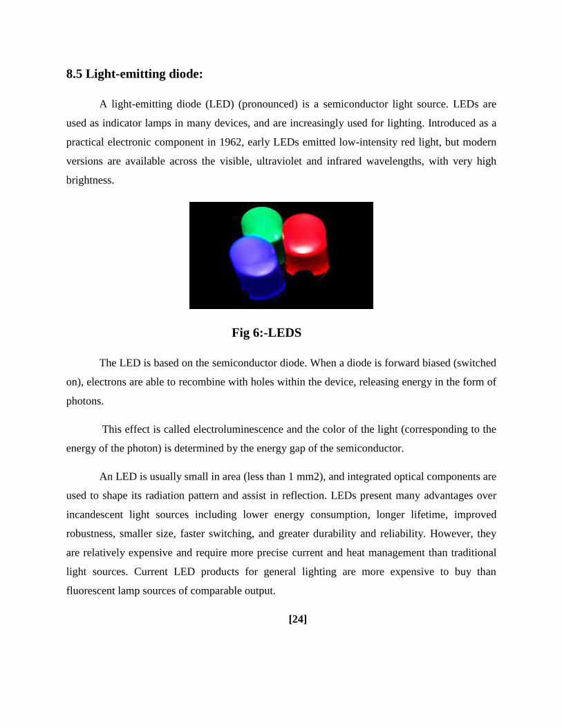
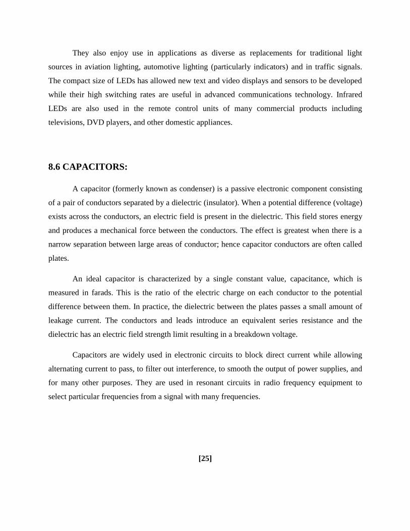
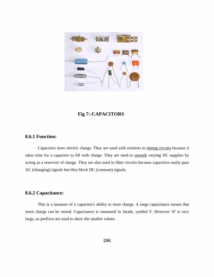
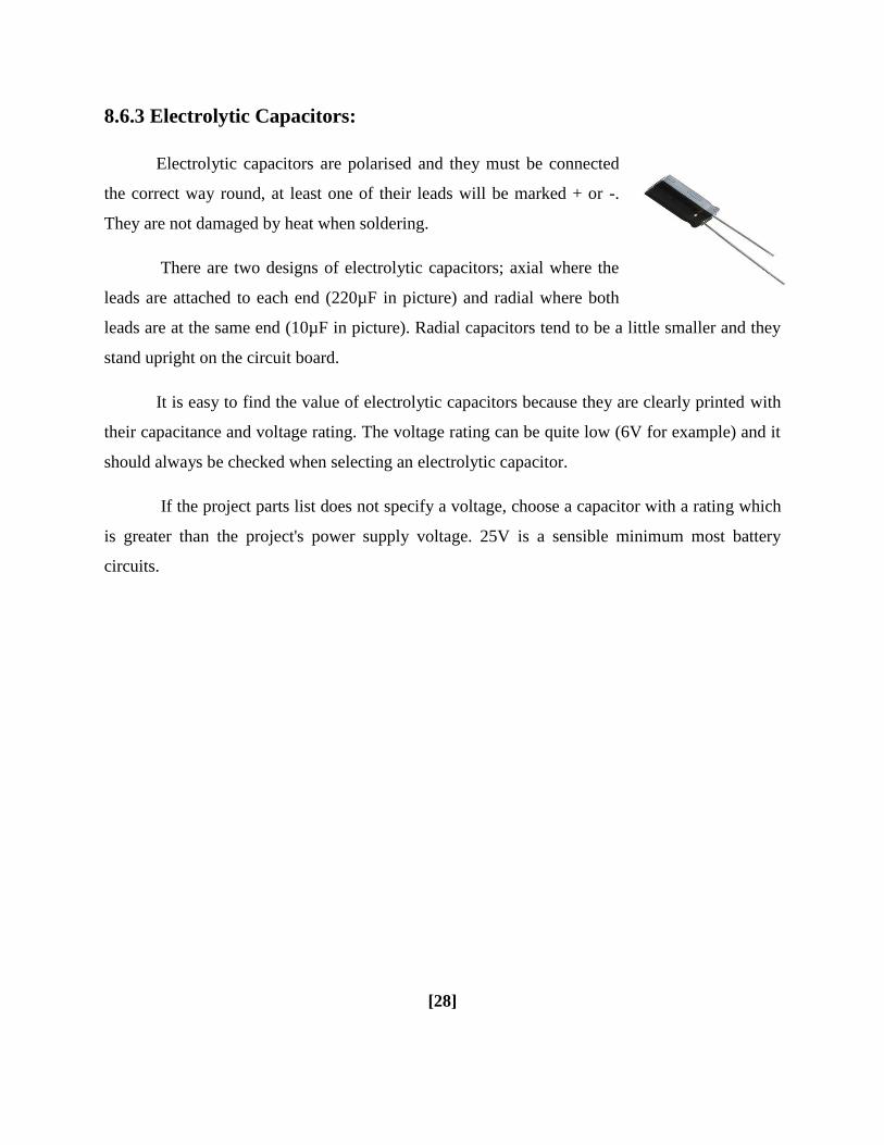
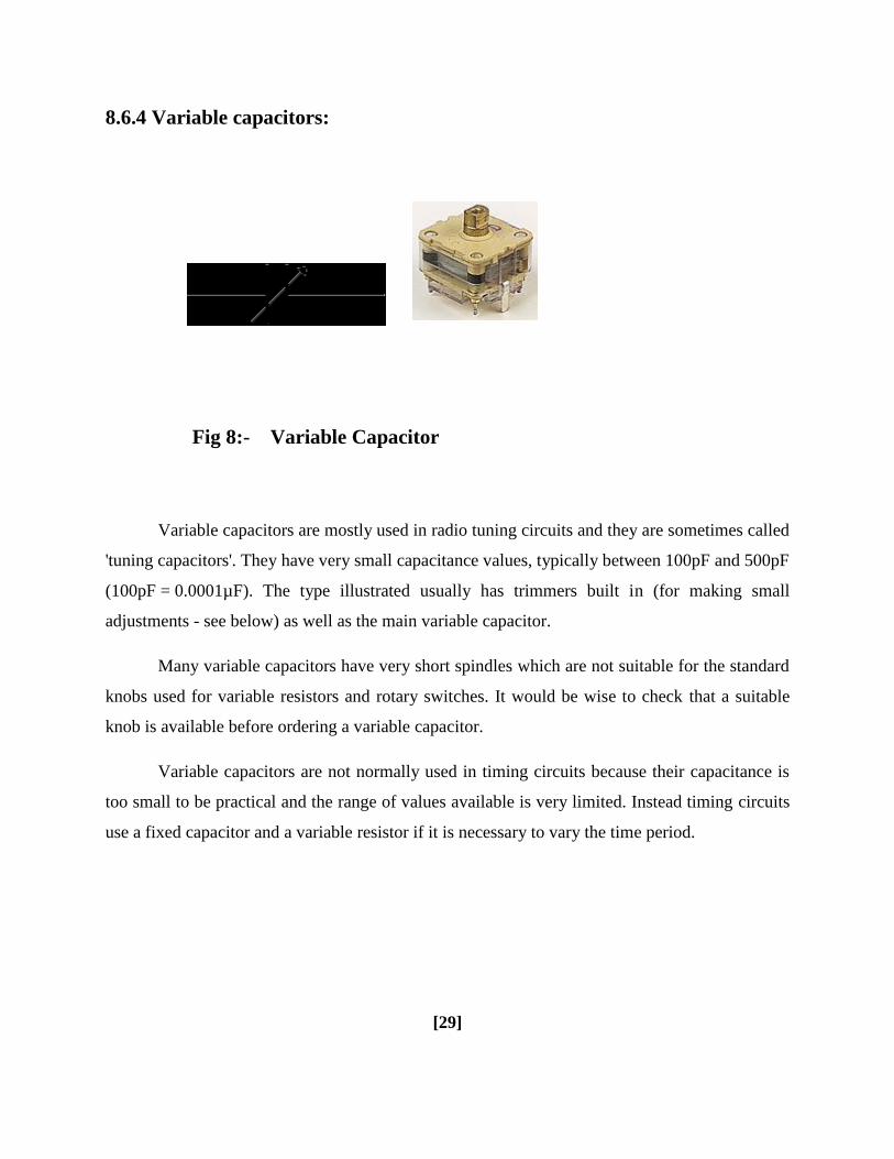
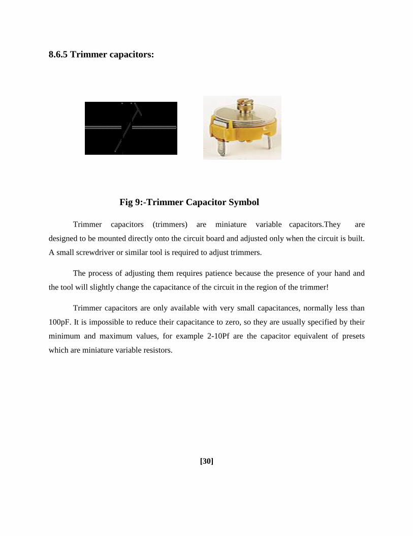
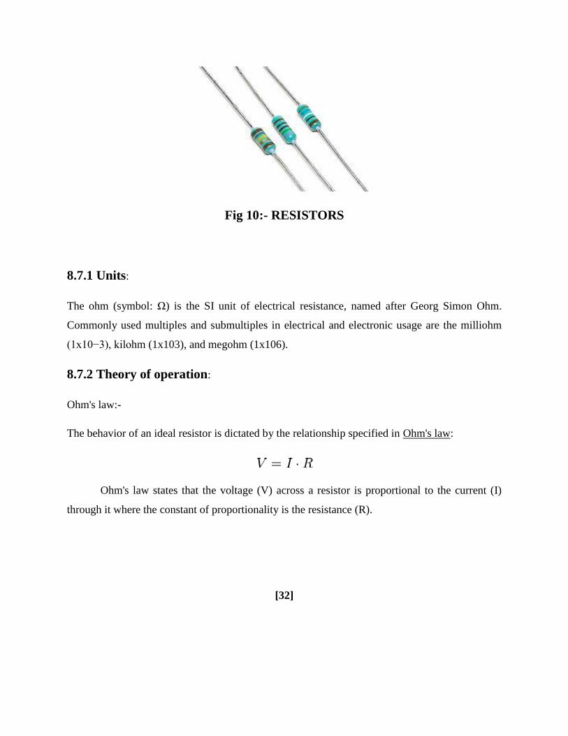
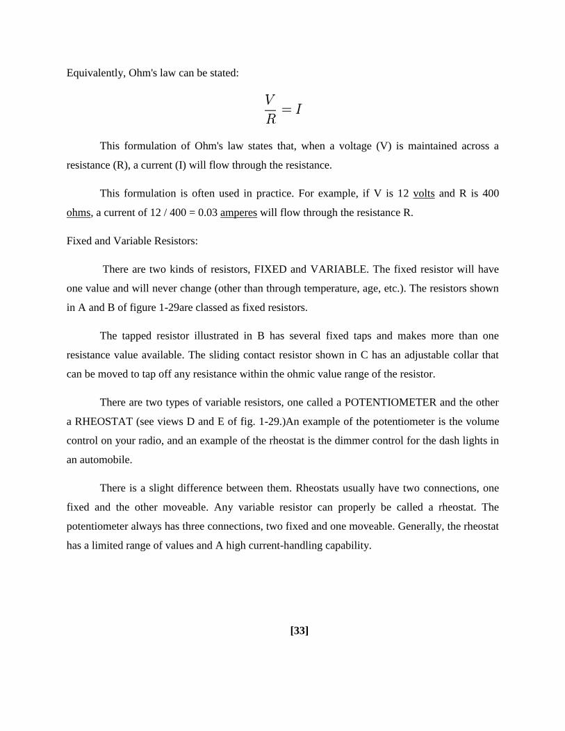
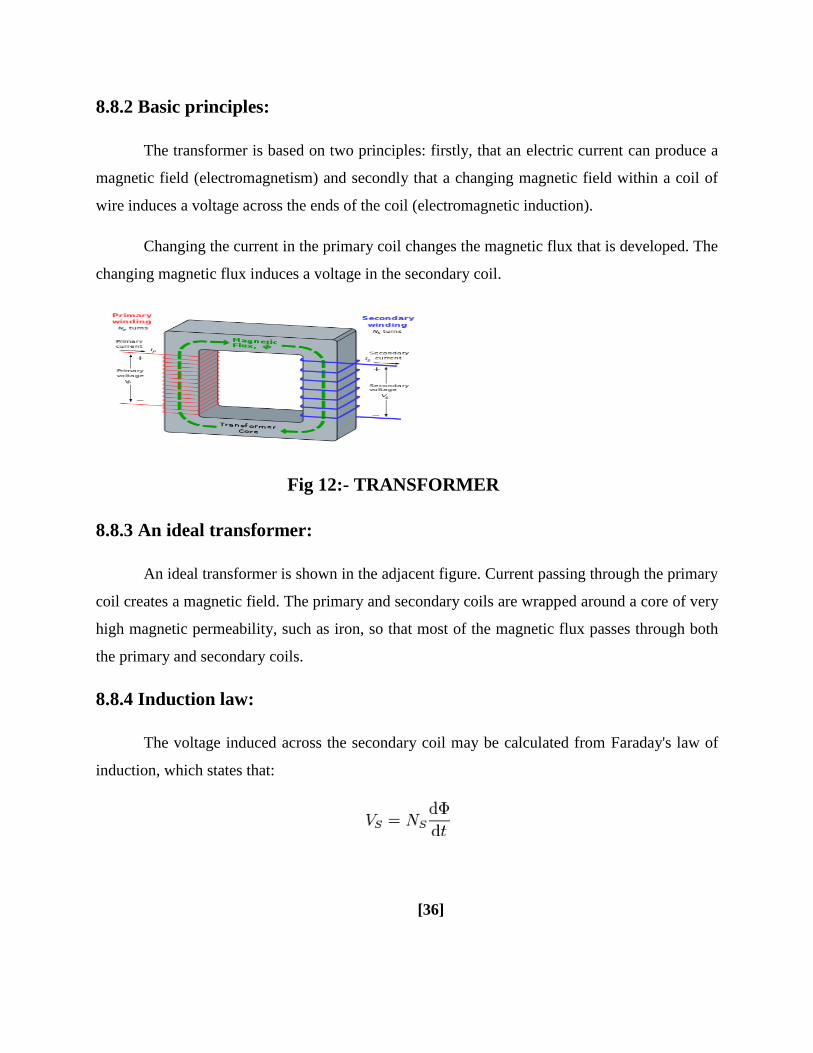
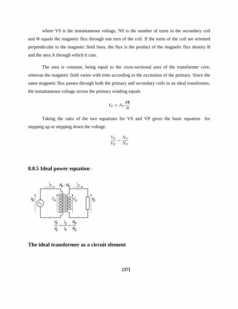
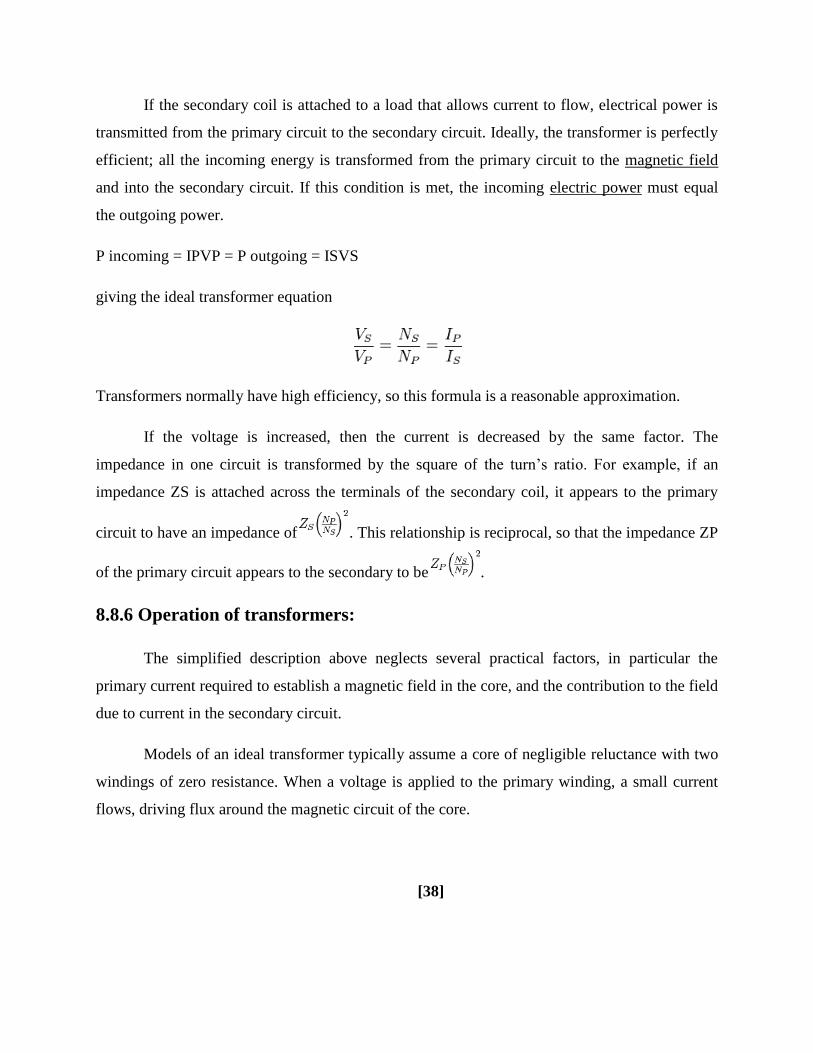
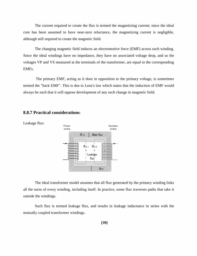
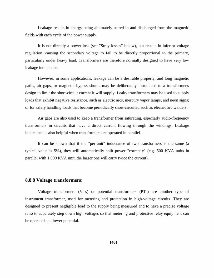
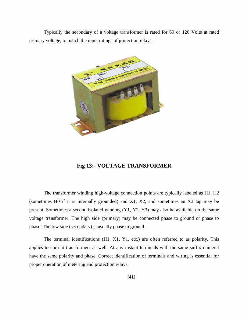
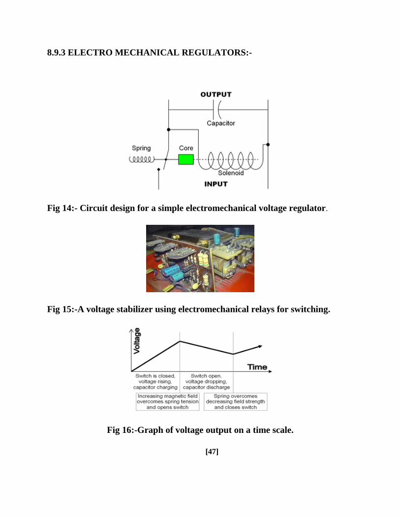
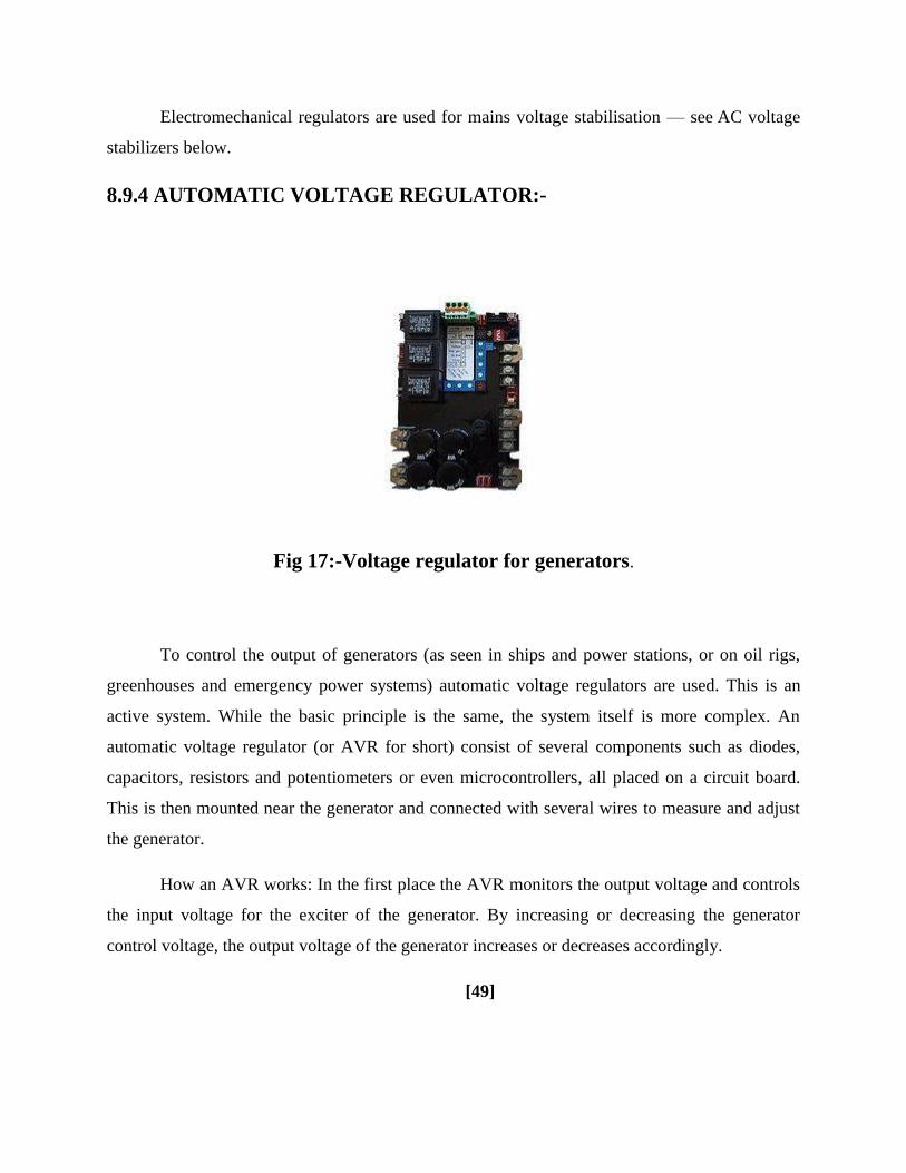
TL1=0
TR0=1
P1=0xFF
IE=0x82
RW24XX(ampc 1 1 0xA1 M2404)
RW24XX(ampd 1 4 0xA1 M2404)
t=d
km=c
distance=t100
c=0d=0
lcd_init()
lcd_com(0x01)
lcd_com(0x0C)
lcd_com(0x80)
while(1)
TR0=1
val=TL0
[55]
TL1=0
TR1=1
one_sec()
speed=TL1
TR1=0
cal=(speed7)
lcd_com(0x80)
lcd_puts(Speed )
display(cal)
lcd_com(0x89)
lcd_data( )
bintoascii(val)
if(speed==0)
c=km
d=t
RW24XX(ampc 1 1 0xA0 M2404)
RW24XX(ampd 1 4 0xA0 M2404)
[56]
if(P1_4==0)
while(P1_4=1)
c=0
RW24XX(ampc 2 1 0xA0 M2404)
[57]
Fig 18- Flow Chart
[58]
10 CONSTRUCTION-
The reed switch and a magnet need to be fixed on the front wheel of the motor bike
(Hero Hondarsquos Splendor)
A small circular magnet(about 2 cm in diametre) normally used in speakers of small
toys can be used Fix the magnet to the cen- tral drum of the wheel just below the spokes
connected to the drum Secure the magnet using hot glue or Araldite For fixing the reed switch
a PVC pipe contraption needs to be made so that the magnet and reed switch are aligned as
shown in Fig 3 The materials required to build the con- traption are shown in Fig 4 Cut a
32cm diameter PVC pipe measuring 152 cm in length perpendicularly into two halves Use
only one half of the PVC pipe Mount and secure the reed switch using Araldite and cable ties on
the plastic handle (normally used in emergency lights) Once it dries up solder two wires to the
two opposite end leads of the reed switch Fix the plastic handle on the half cut PVC pipe using
screws Now place the pipe on the front shock-absorber fork such that reed switch faces to-
wards the magnet Connect a multimeter set in continuity mode to the two wires coming from
the reed switch Rotate the wheel slowly and see whether the reed switch closes when the magnet
passes across it If it does the multimeter will give a continuity beep
When the magnet moves away from the reed switch the beep will stop indicating that
the reed switch is open Make a few trials to find the optimal position for mounting and fixing
the PVC pipe such that the reed switch works smoothly Mark the location on the front shock-ab-
sorber fork
Now you can fix the PVC pipe contraption to the shock-ab- sorber fork us- ing hot glue
as shown in Fig 5 Use liberal amount of hot glue to secure it to the pipe Care- fully route the
two wires up to the bikersquos handle bar using cable ties to secure the wire This com- pletes the
sensor mounting part The main cir- cuit and the LCD module can be housed in suit- able plastic
en- closures which are readily avail- able in electronic projects shops
[59]
These enclosures should have precut slot for easy mounting of the LCD pan- el If such
boxes are not available you can use the plastic boxes of electronic chokes by suitably re- moving
some portions for the LCD panel Power sup- ply can be taken either directly from the bikersquos
12V battery or tapped from the console which houses horn head- light and indicator light
switches For this you need to remove the switch console and identify positive wire and ground
wire using a mul- timeter When carrying out this step remember to turn the ignition key to lsquoonrsquo
position Solder a 60cm two-core wire to the positive and negative terminals inside the switch
console The advantage of taking supply from the switch console is that the ignition key controls
the power supply to the main unit without having a separate on-off switch An actual-size
single-side PCB layout of the microcontroller-based speedometer-cum-odometer is shown in Fig
16 and its component layout in Fig 17
Fig 19-Component layout for PCB
11 TESTING-
After all the components are soldered on the PCB program the microcon- troller with
Init_EEPROMhex file and place the microcontroller in a 20-pin IC base and switch on the
circuit In the first line of the LCD lsquoINIT_EEPROMrsquo appears After five seconds lsquo000000rsquo is
displayed in the second line This process erases any previous data and sets the initial readings in
the EEPROM to zero Now switch off the supply and program the microcontroller with
lsquospeedohexrsquo main file After pro- gramming place the microcontroller back in the circuit and
switch on the supply The LCD will show lsquoKms 000000rsquo in the first line and lsquoSpeed- KmsHr
000rsquo in the second line Now the unit is ready to mount on your bike Connect the two wires
coming from the reed switch and the power supply wires to the main unit Mount the unit at the
centre of the bikersquos handle bar on top of the lsquoUrsquo clamps that secure the handle bar to the chassis
You can use cable ties to accomplish this Mounting arrange- ment of the unit is shown in Fig 6
Now start the bike take a test ride and if connections are correct the speed and the distance will
be displayed on the LCD
[61]
A protective cover like polythene can be used for the main unit on rainy days EFY note
The source codes for this article have been included in this monthrsquos EFY-CD
111 Calculations-
You first need to know the radius of the bikersquos front wheel The calculations here are
based on Hero Hondarsquos Splendor model The radius of the front wheel is 30 cm (This can vary
with the
brand or model) Circumference of the wheel= 2πr (where lsquorrsquo is in cm) = 2times314times30 = 1884 cm
or 1884 meters
1111 Speed-
Letrsquos assume that in 1 second the wheel completes one revolution In other words in one
second the bike has covered 188 metres Therefore the speed in kmhour Ntimes188times36001000 =
Ntimes6784 or Ntimes68 where lsquoNrsquo is the number of revolutions per second lsquo68rsquo is a constant and
only lsquoNrsquo varies for example if lsquoNrsquo is 5 the speed equals 5x68= 34 kmhour
1112 Distance-
The odometer is updated every 100 metres To cover 100 metres the wheel is required to
make approximately 53 revolutions (100188) The microcontroller takes care of the tasks of
revolutions counting speed calculation conversion and display of results
[62]
12 FEATURES-
[1] Digital read out
[2] Speed displayed in kmhr
[3] Distance travelled displayed in km
[4] Readings saved in non volatile memory
[5] Realibility due to use of the microcontroller
[6] No mechanical wear amp tear
[7] Home-brewed speed transducer or sensor
[8] Self reset to zero after completion of 999999km
[9] Easy to built amp fix on the bike
[63]
13 APPLICATION-
[1] It is in luxury cars and motor bike
[2] It is used to measured speed of the motor bike
[3] It measures speed amp quantity of fuel
[4] It is used to counting revolution and speed calculation of cars
[5] It is for conversion of speed and display results
Fig 20- APPLICATION
[64]
14 CONCLUSION-
Considering the total requirement and need of society as well as according to cost
analysis and project profitability statement it is concluded that the project Microcontroller based
speedometer-cum-odometer is technically viable financially feasible and suitable for speed
measurement
[65]
15REFERENCES
[1] B Ravindranath M Chander Power System Protection and Switchgear NEW AGE
INTERNATIONAL PUBLISHERS 2nd
edition 2011 pp31-39148-153255-385
[2] A Chakrabarti M L Soni A Text Book ON POWER SYSTEM ENGINEERING
Dhanpat Rai amp CO 2nd
edition 2010 pp539-578579-616617-632
[3] B L Theraja A K Theraja A Text Book ON ELECTRICAL MACHINES S CHAND
PUBLICATION 1st edition 2005 pp1243-1312
[4] Ashfaq Hussain ELECTRICAL MACHINES DHANPAT RAI ampCO 2nd
edition
2005pp307-416
[5] V K Mehta Rohit Mehta Principles of ELECTRICAL MACHINES S CHAND
PUBLICATION 1st edition 2002 pp313-377
[6] J B Gupta THEORY amp PERFORMANCE of ELECTRICAL MACHINES S K
KATARIA amp SONS 14th
edition 2006 pp359-439
[7] Yang ES ―Fundamentals of Semiconductor Devices chap 1 McGraw Hill Book
Company New York 1978
[8] wwwgooglecom
[9] wwwieeeorg
[10] Wikipedia- httpsenwikipediaorgwikiElectronic_component
[11] All Electronics- wwwallelectronicscom
[12] wwwelectrical4ucom
[13] wwwelectricalengineeringschoolsorg
[14] EFY- httpswwwelectronicsforucom
[15] wwwelectrical-engineering-portalcom
[16] wwwrealworldengineeringorg
[66]
TL1=0
TR1=1
one_sec()
speed=TL1
TR1=0
cal=(speed7)
lcd_com(0x80)
lcd_puts(Speed )
display(cal)
lcd_com(0x89)
lcd_data( )
bintoascii(val)
if(speed==0)
c=km
d=t
RW24XX(ampc 1 1 0xA0 M2404)
RW24XX(ampd 1 4 0xA0 M2404)
[56]
if(P1_4==0)
while(P1_4=1)
c=0
RW24XX(ampc 2 1 0xA0 M2404)
[57]
Fig 18- Flow Chart
[58]
10 CONSTRUCTION-
The reed switch and a magnet need to be fixed on the front wheel of the motor bike
(Hero Hondarsquos Splendor)
A small circular magnet(about 2 cm in diametre) normally used in speakers of small
toys can be used Fix the magnet to the cen- tral drum of the wheel just below the spokes
connected to the drum Secure the magnet using hot glue or Araldite For fixing the reed switch
a PVC pipe contraption needs to be made so that the magnet and reed switch are aligned as
shown in Fig 3 The materials required to build the con- traption are shown in Fig 4 Cut a
32cm diameter PVC pipe measuring 152 cm in length perpendicularly into two halves Use
only one half of the PVC pipe Mount and secure the reed switch using Araldite and cable ties on
the plastic handle (normally used in emergency lights) Once it dries up solder two wires to the
two opposite end leads of the reed switch Fix the plastic handle on the half cut PVC pipe using
screws Now place the pipe on the front shock-absorber fork such that reed switch faces to-
wards the magnet Connect a multimeter set in continuity mode to the two wires coming from
the reed switch Rotate the wheel slowly and see whether the reed switch closes when the magnet
passes across it If it does the multimeter will give a continuity beep
When the magnet moves away from the reed switch the beep will stop indicating that
the reed switch is open Make a few trials to find the optimal position for mounting and fixing
the PVC pipe such that the reed switch works smoothly Mark the location on the front shock-ab-
sorber fork
Now you can fix the PVC pipe contraption to the shock-ab- sorber fork us- ing hot glue
as shown in Fig 5 Use liberal amount of hot glue to secure it to the pipe Care- fully route the
two wires up to the bikersquos handle bar using cable ties to secure the wire This com- pletes the
sensor mounting part The main cir- cuit and the LCD module can be housed in suit- able plastic
en- closures which are readily avail- able in electronic projects shops
[59]
These enclosures should have precut slot for easy mounting of the LCD pan- el If such
boxes are not available you can use the plastic boxes of electronic chokes by suitably re- moving
some portions for the LCD panel Power sup- ply can be taken either directly from the bikersquos
12V battery or tapped from the console which houses horn head- light and indicator light
switches For this you need to remove the switch console and identify positive wire and ground
wire using a mul- timeter When carrying out this step remember to turn the ignition key to lsquoonrsquo
position Solder a 60cm two-core wire to the positive and negative terminals inside the switch
console The advantage of taking supply from the switch console is that the ignition key controls
the power supply to the main unit without having a separate on-off switch An actual-size
single-side PCB layout of the microcontroller-based speedometer-cum-odometer is shown in Fig
16 and its component layout in Fig 17
Fig 19-Component layout for PCB
11 TESTING-
After all the components are soldered on the PCB program the microcon- troller with
Init_EEPROMhex file and place the microcontroller in a 20-pin IC base and switch on the
circuit In the first line of the LCD lsquoINIT_EEPROMrsquo appears After five seconds lsquo000000rsquo is
displayed in the second line This process erases any previous data and sets the initial readings in
the EEPROM to zero Now switch off the supply and program the microcontroller with
lsquospeedohexrsquo main file After pro- gramming place the microcontroller back in the circuit and
switch on the supply The LCD will show lsquoKms 000000rsquo in the first line and lsquoSpeed- KmsHr
000rsquo in the second line Now the unit is ready to mount on your bike Connect the two wires
coming from the reed switch and the power supply wires to the main unit Mount the unit at the
centre of the bikersquos handle bar on top of the lsquoUrsquo clamps that secure the handle bar to the chassis
You can use cable ties to accomplish this Mounting arrange- ment of the unit is shown in Fig 6
Now start the bike take a test ride and if connections are correct the speed and the distance will
be displayed on the LCD
[61]
A protective cover like polythene can be used for the main unit on rainy days EFY note
The source codes for this article have been included in this monthrsquos EFY-CD
111 Calculations-
You first need to know the radius of the bikersquos front wheel The calculations here are
based on Hero Hondarsquos Splendor model The radius of the front wheel is 30 cm (This can vary
with the
brand or model) Circumference of the wheel= 2πr (where lsquorrsquo is in cm) = 2times314times30 = 1884 cm
or 1884 meters
1111 Speed-
Letrsquos assume that in 1 second the wheel completes one revolution In other words in one
second the bike has covered 188 metres Therefore the speed in kmhour Ntimes188times36001000 =
Ntimes6784 or Ntimes68 where lsquoNrsquo is the number of revolutions per second lsquo68rsquo is a constant and
only lsquoNrsquo varies for example if lsquoNrsquo is 5 the speed equals 5x68= 34 kmhour
1112 Distance-
The odometer is updated every 100 metres To cover 100 metres the wheel is required to
make approximately 53 revolutions (100188) The microcontroller takes care of the tasks of
revolutions counting speed calculation conversion and display of results
[62]
12 FEATURES-
[1] Digital read out
[2] Speed displayed in kmhr
[3] Distance travelled displayed in km
[4] Readings saved in non volatile memory
[5] Realibility due to use of the microcontroller
[6] No mechanical wear amp tear
[7] Home-brewed speed transducer or sensor
[8] Self reset to zero after completion of 999999km
[9] Easy to built amp fix on the bike
[63]
13 APPLICATION-
[1] It is in luxury cars and motor bike
[2] It is used to measured speed of the motor bike
[3] It measures speed amp quantity of fuel
[4] It is used to counting revolution and speed calculation of cars
[5] It is for conversion of speed and display results
Fig 20- APPLICATION
[64]
14 CONCLUSION-
Considering the total requirement and need of society as well as according to cost
analysis and project profitability statement it is concluded that the project Microcontroller based
speedometer-cum-odometer is technically viable financially feasible and suitable for speed
measurement
[65]
15REFERENCES
[1] B Ravindranath M Chander Power System Protection and Switchgear NEW AGE
INTERNATIONAL PUBLISHERS 2nd
edition 2011 pp31-39148-153255-385
[2] A Chakrabarti M L Soni A Text Book ON POWER SYSTEM ENGINEERING
Dhanpat Rai amp CO 2nd
edition 2010 pp539-578579-616617-632
[3] B L Theraja A K Theraja A Text Book ON ELECTRICAL MACHINES S CHAND
PUBLICATION 1st edition 2005 pp1243-1312
[4] Ashfaq Hussain ELECTRICAL MACHINES DHANPAT RAI ampCO 2nd
edition
2005pp307-416
[5] V K Mehta Rohit Mehta Principles of ELECTRICAL MACHINES S CHAND
PUBLICATION 1st edition 2002 pp313-377
[6] J B Gupta THEORY amp PERFORMANCE of ELECTRICAL MACHINES S K
KATARIA amp SONS 14th
edition 2006 pp359-439
[7] Yang ES ―Fundamentals of Semiconductor Devices chap 1 McGraw Hill Book
Company New York 1978
[8] wwwgooglecom
[9] wwwieeeorg
[10] Wikipedia- httpsenwikipediaorgwikiElectronic_component
[11] All Electronics- wwwallelectronicscom
[12] wwwelectrical4ucom
[13] wwwelectricalengineeringschoolsorg
[14] EFY- httpswwwelectronicsforucom
[15] wwwelectrical-engineering-portalcom
[16] wwwrealworldengineeringorg
[66]
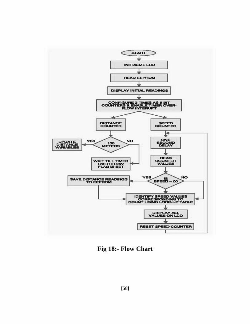
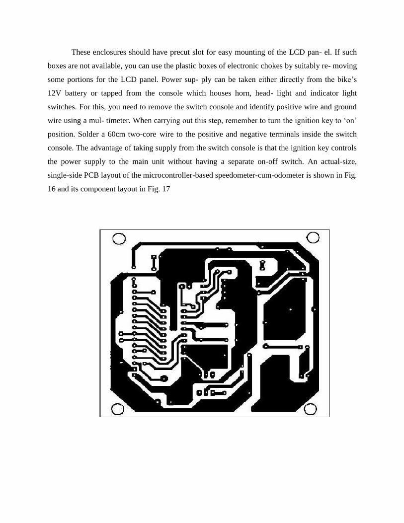
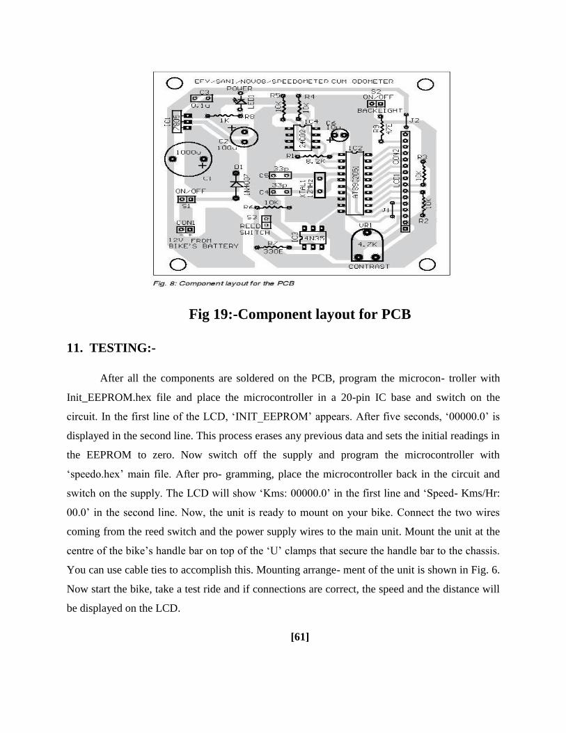
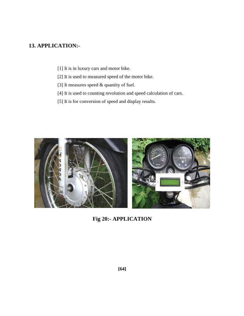