microcontroller based temperature … cost/temperature sensing.pdf · microcontroller-based room...
TRANSCRIPT

MICROCONTROLLER
BASED
TEMPERATURE SENSING
AND CONTROL
SYSTEM

Academic Information
“To Be Done by Student”

Acknowledgement
“To Be Done by Student”
Introduction
Monitoring the temperature of a room is a critical task to ensure the
performance of the server is not disturbed by excessive room
temperature or in corporate office or exceed of limit increasing
rapidly. In this project, we designed and implemented a
microcontroller-based room temperature monitoring system using
Atmel ATmega8 microcontroller and National Semiconductor's
LM35D temperature sensor. The system is equipped with alarm when
temperature goes beyond threshold alarm rings and relay board to
control electronic equipment. The experiment results show that our
system works as expected. The system raises an alarm and when the
room temperature is above threshold, which is 30°C. A Relay will be
ON at 51°C and above.
Working
The working of microcontroller based temperature sensing and
alarming system is totally based on ADC conversion. In this we are
going to use LM35 temperature sensor that is used for temperature
sensing and microcontroller ATMEGA8 for controlling part. In this
project we decide a threshold value for temperature above which
buzzer creates a sound but the intensity of buzzer is low at 30 degree
and its intensity increases after every 5 degree and it will be
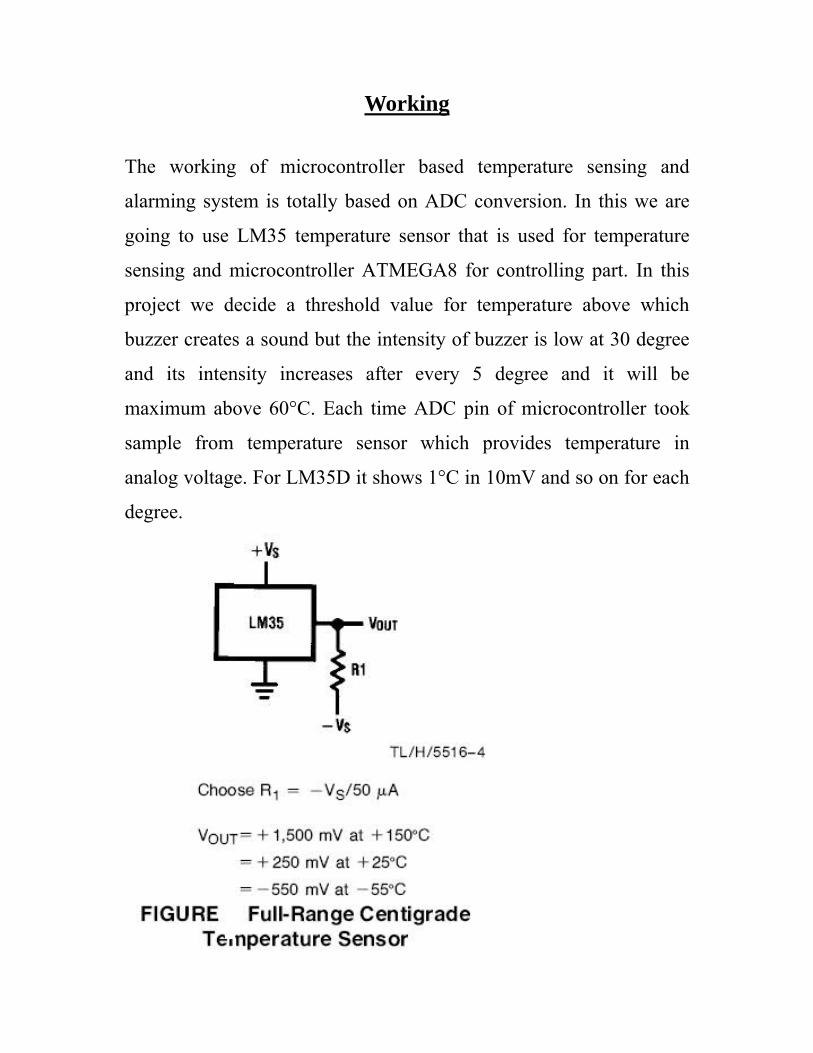
maximum above 60°C. Each time ADC pin of microcontroller took
sample from temperature sensor which provides temperature in
analog voltage. For LM35D it shows 1°C in 10mV and so on for each
degree.
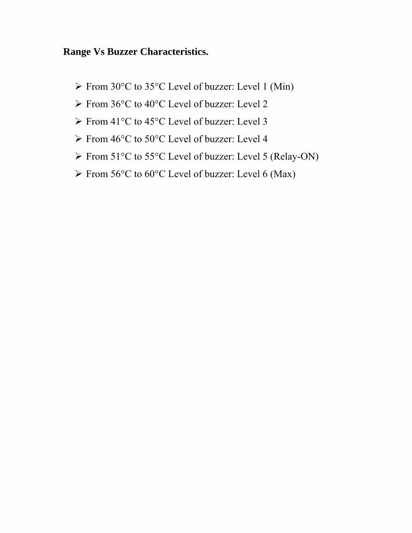
Range Vs Buzzer Characteristics.
From 30°C to 35°C Level of buzzer: Level 1 (Min)
From 36°C to 40°C Level of buzzer: Level 2
From 41°C to 45°C Level of buzzer: Level 3
From 46°C to 50°C Level of buzzer: Level 4
From 51°C to 55°C Level of buzzer: Level 5 (Relay-ON)
From 56°C to 60°C Level of buzzer: Level 6 (Max)

Circuit & Component Description
Temperature (LM-35D)
The LM35 series are precision integrated-circuit temperature devices
with an output voltage linearly-proportional to the Centigrade
temperature. The LM35 device has an advantage over linear
temperature sensors calibrated in Kelvin, as the user is not required to
subtract a large constant voltage from the output to obtain convenient
Centigrade scaling. The LM35 device does not require any external
calibration or trimming to provide typical accuracies of ±¼°C at room
temperature and ±¾°C over a full −55°C to 150°C temperature range.
Lower cost is assured by trimming and calibration at the wafer level.
The low-output impedance, linear output, and precise inherent
calibration of the LM35 device makes interfacing to readout or

control circuitry especially easy. The device is used with single power
supplies, or with plus and minus supplies. As the LM35 device draws
only 60 μA from the supply, it has very low self-heating of less than
0.1°C in still air. The LM35 - An Integrated Circuit Temperature
Sensor
• You can measure temperature more accurately than a using a
thermostat.
• The sensor circuitry is sealed and not subject to oxidation, etc.
• The LM35 generates a higher output voltage than thermocouples
and may not require that the output voltage be amplified.
Working of LM35
o It has an output voltage that is proportional to the Celsius
temperature.
o The scale factor is .01V/oC
o The LM35 does not require any external calibration or
trimming and maintains an accuracy of +/-0.4 oC at room
temperature and +/- 0.8 oC over a range of 0 oC to +100 oC.
o Another important characteristic of the LM35DZ is that it
draws only 60 micro amps from its supply and possesses a
low self-heating capability. The sensor self-heating causes
less than 0.1 oC temperature rise in still air.
The LM35 comes in many different packages, including the
following.

• TO-92 plastic transistor-like package,
• T0-46 metal can transistor-like package
• 8-lead surface mount SO-8 small outline package
o Here is a photo of the LM 35 test on a circuit board.
The white wire in the photo goes to the power
supply.
Both the resistor and the black wire go to ground.
The output voltage is measured from the middle pin
to ground.

Microcontroller (Atmega-8A)
Features
• High-performance, Low-power 8-bit Microcontroller
• Advanced RISC Architecture
Most Single-clock Cycle Execution
32 x 8 General Purpose Working Registers
Fully Static Operation
Up to 16MIPS Throughput at 16MHz
On-chip 2-cycle Multiplier
• High Endurance Non-volatile Memory segments
8KBytes of In-System Flash program memory
512Bytes EEPROM

1KByte Internal SRAM
Write/Erase Cycles: 10,000 Flash/100,000 EEPROM
Data retention: 20 years at 85 Deg C/100 years at 25 Deg C
Optional Boot Code Section with Independent Lock Bits
• In-System Programming by On-chip Boot Program
• True Read-While-Write Operation
Programming Lock for Software Security
• Atmel QTouch library support
Capacitive touch buttons, sliders and wheels
Atmel QTouch and QMatrix acquisition
Up to 64 sense channels
• Peripheral Features
Two 8-bit Timer/Counters
One 16-bit Timer/Counter
Real Time Counter with Separate Oscillator
Three PWM Channels
• Eight Channels 10-bit Accuracy
6-channel ADC in PDIP package
• Six Channels 10-bit Accuracy
Byte-oriented Two-wire Serial Interface
Programmable Serial USART
Master/Slave SPI Serial Interface
Programmable Watchdog Timer with Separate On-chip Oscillator
On-chip Analog Comparator

• Special Microcontroller Features
Power-on Reset and Programmable Brown-out Detection
Internal Calibrated RC Oscillator
External and Internal Interrupt Sources
Five Sleep Modes
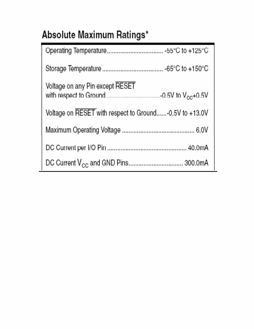
• Operating Voltages
2.7 - 5.5V
0 - 16MHz
Atmega-8 PDIP Pin Diagram
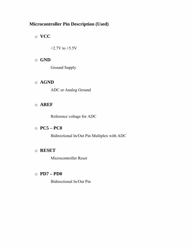
Microcontroller Pin Description (Used)
o VCC
+2.7V to +5.5V
o GND Ground Supply
o AGND ADC or Analog Ground
o AREF
Reference voltage for ADC
o PC5 – PC0 Bidirectional In/Out Pin Multiplex with ADC
o RESET Microcontroller Reset
o PD7 – PD0 Bidirectional In/Out Pin

Now a
relays
are ope
electro
carried
operati
applica
a days mo
for their
erated bo
omagnet a
d out with
ing princi
ations. M
ost of the
effective
oth electri
and also a
h the hel
iples for i
ost of the
R
e high end
e working
ically and
a set of co
lp of the
its workin
e devices
Relay
d industri
g. Relays
d mechan
ontacts. T
electrom
ng. But th
have the
ial applic
s are simp
ically. Re
The switc
magnet. Th
hey differ
applicati
cation dev
ple switch
elays con
ching mec
here are
r accordin
on of rela
vices hav
hes whic
nsist of a
chanism i
also othe
ng to thei
ays.
ve
ch
n
is
er
ir

The m
power
where
applica
played
main oper
signal ca
only one
ation of r
d an impo
ation of
an be use
e signal c
relays star
ortant rol
a relay c
d to cont
can be u
rted durin
e in swit
comes in
trol a circ
sed to co
ng the inv
tching ca
n places w
cuit. It is
ontrol a l
vention o
alls in tel
where on
also used
lot of cir
of telepho
ephone e
nly a low
d in place
rcuits. Th
ones. The
exchanges
w-
es
he
ey
s.

They were also used in long distance telegraphy. They were used to
switch the signal coming from one source to another destination.
After the invention of computers they were also used to perform
Boolean and other logical operations. The high end applications of
relays require high power to be driven by electric motors and so on.
Such relays are called contactors.

ULN2
contain
A Darl
003 is a
ns seven o
lington pa
high volt
open coll
air is an a
ULN-20
tage and
lector Dar
arrangeme
003 Driv
high cur
rlington p
ent of two
ver
rrent Darl
pairs with
o bipolar
lington ar
h common
transistor
rray IC. I
n emitters
rs.
It
s.
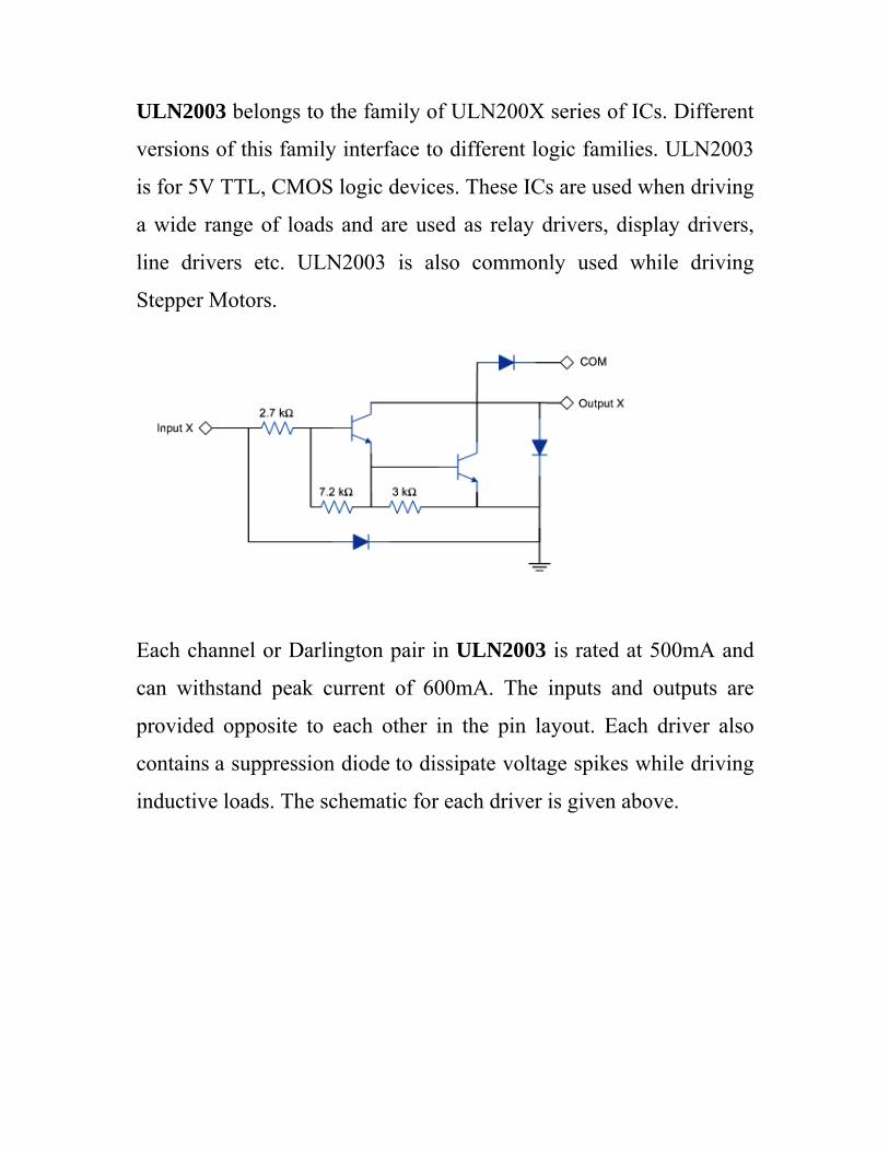
ULN2003 belongs to the family of ULN200X series of ICs. Different
versions of this family interface to different logic families. ULN2003
is for 5V TTL, CMOS logic devices. These ICs are used when driving
a wide range of loads and are used as relay drivers, display drivers,
line drivers etc. ULN2003 is also commonly used while driving
Stepper Motors.
Each channel or Darlington pair in ULN2003 is rated at 500mA and
can withstand peak current of 600mA. The inputs and outputs are
provided opposite to each other in the pin layout. Each driver also
contains a suppression diode to dissipate voltage spikes while driving
inductive loads. The schematic for each driver is given above.

Power Supply Section
Power supply is a reference to a source of electrical power. A device
or system that supplies electrical or other types of energy to an output
load or group of loads is called a power supply unit or PSU. The term
is most commonly applied to electrical energy supplies, less often to
mechanical ones, and rarely to others.
Here in our application we need a 5v DC power supply for all
electronics involved in the project. This requires step down
transformer, rectifier, voltage regulator, and filter circuit for
generation of 5v DC power. A brief description of all the components
is given as follows:
Circuit Diagram for power supply

Transformer
A transformer is a device that transfers electrical energy from one
circuit to another through inductively coupled conductors — the
transformer's coils or "windings". Except for air-core transformers,
the conductors are commonly wound around a single iron-rich core,
or around separate but magnetically-coupled cores. A varying current
in the first or "primary" winding creates a varying magnetic field in
the core (or cores) of the transformer. This varying magnetic field
induces a varying electromotive force (EMF) or "voltage" in the
"secondary" winding. This effect is called mutual induction.
If a load is connected to the secondary circuit, electric charge will
flow in the secondary winding of the transformer and transfer energy
from the primary circuit to the load connected in the secondary
circuit.
The secondary induced voltage VS, of an ideal transformer, is scaled
from the primary VP by a factor equal to the ratio of the number of
turns of wire in their respective windings:

By appropriate selection of the numbers of turns, a transformer thus
allows an alternating voltage to be stepped up — by making NS more
than NP — or stepped down, by making it
Bridge Rectifier
A bridge rectifier makes use of four diodes in a bridge arrangement to
achieve full-wave rectification. This is a widely used configuration,
both with individual diodes wired as shown and with single
component bridges where the diode bridge is wired internally.

Diode
A diod
through
semico
diode i
one dir
here.
A
C
D
fr
D
This sy
meanin
Curren
de is a s
h it in o
onductor
is specifi
rection. S
A diode c
Current) to
Diodes c
frequencie
Diodes ca
ymbol
ng of the
nt flows
semicond
only one
device, i
cally mad
Some wa
an be use
o DC (Di
can be
es.
an be use
is use
symbol is
from
ductor de
e directio
it does no
de to allo
ys in wh
ed as a re
irect Curr
used to
ed as an
d to indic
s (Ano
the ano
evice whi
on. Altho
ot operat
ow curren
hich the d
ectifier th
rent) for a
separat
on/off sw
cate a dio
ode)
ode side
ich allow
ough a tr
te the wa
nt to flow
diode can
at conver
a power s
e the s
witch tha
ode in a ci
(Cathod
e to th
ws curren
ransistor
ay a diod
w through
n be used
rts AC (A
upply dev
signal fr
at control
ircuit dia
de).
he catho
nt to flow
is also
de does. A
h it in onl
are liste
Alternatin
vice.
om radi
ls curren
gram. Th
ode side
w
a
A
ly
ed
ng
io
nt.
he
e.

Althou
differe
followi
Light e
The
This ty
forwar
ugh all dio
nt types
ing devic
emitting
circuit
ype of di
rd directio
odes oper
suited t
ces are be
diode
symbol
iode emit
on. (Forw
rate with
to differe
st used fo
is
ts light w
ward biase
the same
ent appli
or the app
when curr
ed)
e general
ications.
plications
rent flow
principle
For exa
noted.
ws through
e, there ar
ample, th
h it in th
re
he
.
he
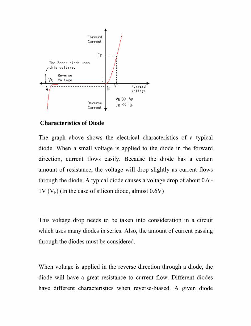
Characteristics of Diode
The graph above shows the electrical characteristics of a typical
diode. When a small voltage is applied to the diode in the forward
direction, current flows easily. Because the diode has a certain
amount of resistance, the voltage will drop slightly as current flows
through the diode. A typical diode causes a voltage drop of about 0.6 -
1V (VF) (In the case of silicon diode, almost 0.6V)
This voltage drop needs to be taken into consideration in a circuit
which uses many diodes in series. Also, the amount of current passing
through the diodes must be considered.
When voltage is applied in the reverse direction through a diode, the
diode will have a great resistance to current flow. Different diodes
have different characteristics when reverse-biased. A given diode

should be selected depending on how it will be used in the circuit.
The current that will flow through a diode biased in the reverse
direction will vary from several mA to just µA, which is very small.
The limiting voltages and currents permissible must be considered on
a case by case basis. For example, when using diodes for rectification,
part of the time they will be required to withstand a reverse voltage. If
the diodes are not chosen carefully, they will break down.
Regulator (lm7805)
It is a three pin IC used as a voltage regulator. It converts unregulated
DC current into regulated DC current.
Normally we get fixed output by connecting the voltage regulator at
the output of the filtered DC (see in above diagram). It can also be
used in circuits to get a low DC voltage from a high DC voltage (for
example we use 7805 to get 5V from 12V). There are two types of
voltage regulators 1. Fixed voltage regulators (78xx, 79xx) 2.
Variable voltage regulators (LM317) In fixed voltage regulators there
is another classification 1. +ve voltage regulators 2. -ve voltage
regulators POSITIVE VOLTAGE REGULATORS This include 78xx
voltage regulators. The most commonly used ones are 7805 and 7812.
7805 gives fixed 5V DC voltage if input voltage is in (7.5V, 20V).
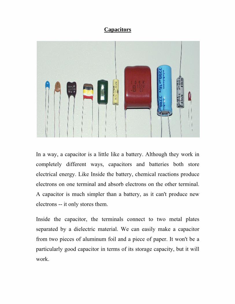
Capacitors
In a way, a capacitor is a little like a battery. Although they work in
completely different ways, capacitors and batteries both store
electrical energy. Like Inside the battery, chemical reactions produce
electrons on one terminal and absorb electrons on the other terminal.
A capacitor is much simpler than a battery, as it can't produce new
electrons -- it only stores them.
Inside the capacitor, the terminals connect to two metal plates
separated by a dielectric material. We can easily make a capacitor
from two pieces of aluminum foil and a piece of paper. It won't be a
particularly good capacitor in terms of its storage capacity, but it will
work.

The dielectric can be any non-conductive substance. However, for
practical applications, specific materials are used that best suit the
capacitor's function. The dielectric dictates what kind of capacitor it is
and for what it is best suited. Depending on the size and type of
dielectric, some capacitors are better for high frequency uses, while
some are better for high voltage applications. Capacitors serve any
purpose, from the smallest plastic capacitor in your calculator, to an
ultra capacitor that can power a commuter bus. NASA uses glass
capacitors to help wake up the space shuttle's circuitry and help
deploy space probes. Here are some of the various types of capacitors.
• Air - Often used in radio tuning circuits
• Mylar - Most commonly used for timer circuits
• Glass - Good for high voltage applications
• Ceramic - Used for high frequency purposes like antennas
• Super capacitor – Powers Electric & Hybrid Cars

Electri
particle
electric
them.
crystal
playgro
fixed
electric
puts u
Plastic
same c
long, r
city flow
es inside
city well
In metal
line stru
ound). A
in place
city with
up relativ
are entir
crystalline
epetitive
ws through
e atoms
are ones
ls, for ex
ucture (a
Although m
, some
them. Th
vely little
rely differ
e structur
chains ca
Re
h a mater
Broadly
s that allo
xample,
a bit lik
most of t
can swa
hat's why
resistan
rent. Alth
re. Their
alled poly
sistor
rial carrie
y speakin
ow electr
the atom
ke a me
the electr
arm throu
metals ar
ce to ele
hough oft
molecule
ymers) are
d by elec
ng, mater
rons to fl
ms are lo
etal clim
rons insid
ugh the
re good c
ectrons f
en solid,
es (which
e bonded
ctrons, tin
rials tha
flow freel
cked into
mbing fra
de these
structure
conductor
flowing th
they don
h are typi
together
ny charge
at conduc
ly throug
o a solid
ame in
atoms ar
e carryin
rs: a meta
hrough i
't have th
ically ver
in such a
ed
ct
gh
d,
a
re
ng
al
t.
he
ry
a
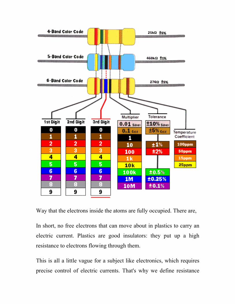
Way that the electrons inside the atoms are fully occupied. There are,
In short, no free electrons that can move about in plastics to carry an
electric current. Plastics are good insulators: they put up a high
resistance to electrons flowing through them.
This is all a little vague for a subject like electronics, which requires
precise control of electric currents. That's why we define resistance
more precisely as the voltage in volts required making a current of 1
amp flow through a circuit. If it takes 500 volts to make 1 amp flow,
the resistance is 500 ohms (written 500 Ω). The relationship written
out as a mathematical equation:
V = I × R
This is known as Ohm's Law. Figure above shows color coding of
resistor.
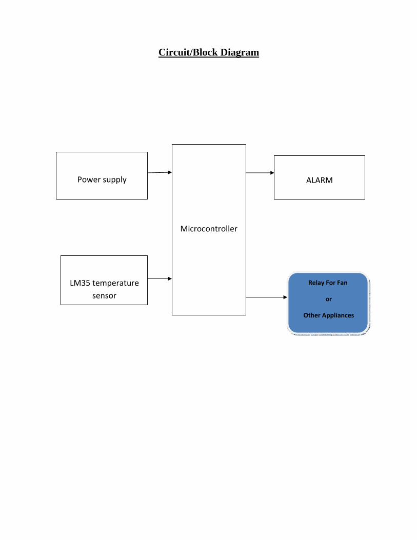
Circuit/Block Diagram
Microcontroller
Power supply
ALARM
LM35 temperature sensor
Relay For Fan
or
Other Appliances

Software Requirement
Cross Compiler : AVR Studio 6.0
Atmel Studio 6 is the integrated development platform (IDP) for
developing and debugging Atmel ARM Cortex-M and Atmel AVR
microcontroller (MCU) based applications. The Atmel Studio 6 IDP
gives you a seamless and easy-to-use environment to write, build and
debug your applications written in C/C++ or assembly code.
Atmel Studio 6 is free of charge and is integrated with the Atmel
Software Framework (ASF)—a large library of free source code with
1,600 ARM and AVR project examples. ASF strengthens the IDP by
providing, in the same environment, access to ready-to-use code that
minimizes much of the low-level design required for projects. Use the
IDP for our wide variety of AVR and ARM Cortex-M processor-
based MCUs, including our broadened portfolio of Atmel SAM3
ARM Cortex-M3 and M4 Flash devices.
Atmel Studio 6.2 is now available, adding advanced debugging
features such as Data and Interrupt Trace, improved RTOS
integration, and better ability to debug code that has been optimized.
With the introduction of Atmel Gallery and Atmel Spaces, Atmel
Studio 6 further simplifies embedded MCU designs to reduce
development time and cost. Atmel Gallery is an online apps store for

development tools and embedded software. Atmel Spaces is a cloud-
based collaborative development workspace allowing you to host
software and hardware projects targeting Atmel MCUs.
In summary, standard integrated development environments (IDEs)
are suited for creating new software for an MCU project. By contrast,
the Atmel Studio 6 IDP also:
• Facilitates reuse of existing software and, by doing so, enables
design differentiation.
• Supports the product development process with easy access to
integrated tools and software extensions through Atmel Gallery.
• Reduces time to market by providing advanced features, an
extensible software eco-system, and powerful debug integration.
Programming Language : Embedded C
Looking around, we find ourselves to be surrounded by various types
of embedded system. Be it a digital camera or a mobile phone or a
washing machine, all of them has some kind of processor functioning
inside it. Associated with each processor is the embedded software. If
hardware forms the body of an embedded system, embedded
processor acts as the brain, and embedded software forms its soul. It
is the embedded software which primarily governs the functioning of
embedded systems.

During infancy years of microprocessor based systems, programs
were developed using assemblers and fused into the EPROMs. There
used to be no mechanism to find what the program was doing. LEDs,
switches, etc. were used to check correct execution of the program.
Some ‘very fortunate’ developers had In-circuit Simulators (ICEs),
but they were too costly and were not quite reliable as well.
As time progressed, use of microprocessor-specific assembly-only as
the programming language reduced and embedded systems moved
onto C as the embedded programming language of choice. C is the
most widely used programming language for embedded
processors/controllers. Assembly is also used but mainly to
implement those portions of the code where very high timing
accuracy, code size efficiency, etc. are prime requirements.
Initially C was developed by Kernighan and Ritchie to fit into the
space of 8K and to write (portable) operating systems. Originally it
was implemented on UNIX operating systems. As it was intended for
operating systems development, it can manipulate memory addresses.
Also, it allowed programmers to write very compact codes. This has
given it the reputation as the language of choice for hackers too.
Result
The system detect the level of temperature in the room if it exceeds
the safety level then activate the audio alarm which includes Buzzer
to alert the user at or out of room in abnormal condition and to take
the necessary action. It also set a relay output at more than 50 Degree.
We found that sensor has a high sensitivity and fast response time.
The sensor’s output is an analog resistance but need to design divider
in case of we need output at low level.

Conclusion
In this project, we have designed and implemented a microcontroller-
based system for monitoring room temperature. We utilized Atmel
AVR ATmega8 microcontroller and LM35D temperature sensor.
Based on the testing results, the system works according to our
predefined specification. This system can be used to help the
administrator to monitor room temperature and control electronic
appliances in real-time using alarming system, in case the
administrator in not inside the room.
References
1. “AVR and embedded system” by Mazidi and Mazidi
2. All datasheets from www.datasheetcatalog.com
3. About ATMEGA8 from www.atmel.com
4. And www.triindia.co.in