microcontroller: power, dc characteristics, i2c interfaceamarjeet/...power_dc-char_i2c.pdf ·...
TRANSCRIPT

Microcontroller: Power, DC Characteristics, I2C Interface
Presented by Nipun Batra
February 2, 2013

Analog Sensors - Temperature
2
AD22103 temperature sensor by Analog Devices Temperature coefficient of 28 mV/oC Output proportional to T*VS Temperature span: 0 - 100 oC Price - $1.65 Transfer function: VOUT = (VS/3.3) X [0.25 + 0.028 X TA]

3
TSL250R light sensor by TAOS (Texas Advanced Optical Solutions, spinoff of TI)
Consists of photodiode and an integrated amplifier Converts light intensity to a voltage Typical responsivity: 137 mV/(uW/cm2) at
wavelength of 635 nm Typical current consumption: 1 mA Maximum output voltage for a supply of 5V ~ 4V
Loose resolution if we connect directly to 5V ADC What is the solution?
Analog Sensors - Light
4
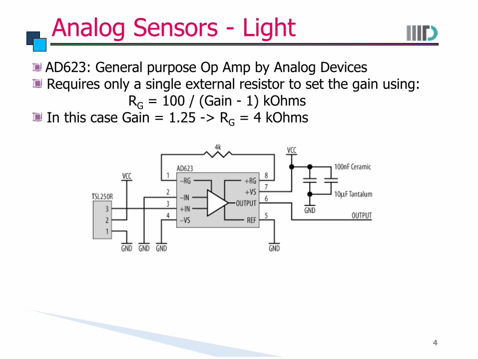
AD623: General purpose Op Amp by Analog Devices Requires only a single external resistor to set the gain using:
RG = 100 / (Gain - 1) kOhms In this case Gain = 1.25 -> RG = 4 kOhms
Analog Sensors - Light

Analog Sensor - Accelerometer
5
ADXL150 single-axis accelerometer by Analog Devices Use for measuring gentle vibrations to violent physical shocks
such as car-crash On-chip signal conditioning and amplification Output proportional to both the acceleration and supply
voltage: VOUT = VS/2 - (sensitivity * VS/5 * acceleration) Typical value of sensitivity = 38.0

Voltage Regulators
6
Converts a range of input DC voltage to a fixed output DC voltage Used to provide a constant supply voltage within a system Removes noise and provides isolation from external supply voltage
Why constant supply voltage?
Many devices operate on fixed voltage Need to know the supply voltage for ADC to decide the sampled value
Primarily 3 types of voltage regulators: Linear regulator: Produce lower voltage than supply voltage Switching regulator: Step-up/step-down or invert the voltage Charge pumps: Step-up/step-down/invert but with limited current
drive capability
Conversion process is not 100% efficient: Current used for regulator itself is called quiescent current

LM78xx Regulators
7
Most commonly used voltage regulators Manufactured by several vendors: Fairchild, ST Microelectronics Part number denotes the output voltage
LM7805 - 5 V output LM7812 - 12 V output
Typical output current of 1 A Quiescent current between 5 and 8 mA
Decoupling capacitors (typically in the range 10 uF and 47 uF are used at input and output)
For negative voltages, use LM79xx regulators
MAX603 Regulators
8
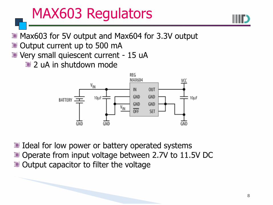
Max603 for 5V output and Max604 for 3.3V output Output current up to 500 mA Very small quiescent current - 15 uA
2 uA in shutdown mode
Ideal for low power or battery operated systems Operate from input voltage between 2.7V to 11.5V DC Output capacitor to filter the voltage

MAX1615 Regulators
9
Micropower Linear Regulators Only supply 30 mA of output current Maximum of 8 uA of Quiscent current
Less than 1 uA of shutdown current
Use this as power source for modules within the embedded system - shutdown the modules when not in use
Operate from input voltage between 4V to 28V DC 5/3 pin determines the output voltage - 1 implies 5V output

Decoupling Capacitors
10
Capacitors used to separate (decouple) one part of electrical circuit from another
Connect them to the input supply for each device on board Provides a path to the ground for any noise present in the power
supply Also act as a source of transient current required when the device
must switch its outputs or internal state Some devices have in-built decoupling capacitors to save on-board
space Look into the datasheet to decide when you should put external
decoupling capacitor

Pull up/down Resistors
11
Used in logic circuits to ensure that a line is set at expected voltage levels if external devices are disconnected (or if no active devices are connected on the line)
Why use a resistor? What value should be a resistor?

12
AVR32: DC Characteristics
Absolute maximum ratings (AVR32)
Found in the Section “Electrical Characteristics” in the datasheet Stresses beyond “Absolute Maximum Ratings” may cause
permanent damage to the device and hence should be avoided

13
Common DC Characteristics

14
Common DC Characteristics
VDDCORE represents core operating voltage Max value of VIL denotes highest value where the pin is guaranteed
to be read as 0 Min value of VIH denotes lowest value where the pin is guaranteed
to be read as 1 When a pin is output high, it will be the source of current
Some devices may have an upper limit on total aggregate current as well on a group of pins e.g. Sum of all IOH for ports C0-C5, D0-D4, ADC7, RESET should not exceed 150 mA (ATmega)
When a pin is output low, it will sink current Negative value since the current is going in Similar to IOH, some devices have upper limit on aggregate IOL
as well e.g. sum of IOL on ports C0-C5, ADC6, ADC7 should not exceed 100 mA (ATmega)
Value of pull up resistors based upon the current ratings

15
Regulator Characteristics
Internal voltage regulator Can supply voltage to other devices on board
With limited current capabilities Decoupling requirements also typically specified ADC voltage input range also specified

16
Caution While Interconnecting
Threshold for logic high and logic low vary across devices For an input device to recognize the signal as high or low, the
output device must provide the signal appropriately Interfacing AT25DF641 Flash with ATMEGA328P
Absolute Maximum Ratings
Operating Range
17
Caution While Interconnecting
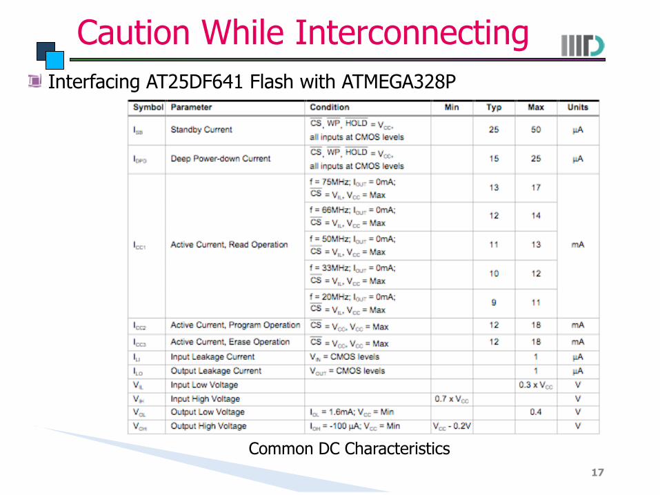
Interfacing AT25DF641 Flash with ATMEGA328P
Common DC Characteristics

Inter-Integrated Circuit (I2C)
18
One of the most common ways to interconnect devices within embedded systems
In existence for more than 20 years, invented by Phillips Data rate - 100 kbps (standard mode) 400 kbps (fast mode) Two wire interface: SDA (Serial Data) and SCL (Serial Clock) Bus is bidirectional Devices may be attached/detached without affecting other devices

Inter-Integrated Circuit (I2C)
19
Both SDA and SCL are pulled up to a positive supply Bus remains high when not in use
A device using the bus drives the line high/low as appropriate Each device connected to I2C bus has unique address and can act as
either transmitter (master), receiver (slave) or both
Multi-master bus: More than one device may assume the role of master: In case of conflict, only one continues and rest abort
I2C transaction begins with SDA going low followed by SCL: indicates that a packet transmission is commencing
While SCL is low, SDA transitions (high or low) for the first valid data byte (“START” condition)

I2C: Data Transmission
20
For each transmitted bit, it becomes valid on SDA while SCL is low The bit is sampled on the rising edge of SCL and must remain valid until
the falling edge of SCL SDA transitions to the next bit before SCL goes high once more
The transaction completes by SCL returning high (inactive) followed by SDA (“STOP” condition)

I2C: Acknowledgement
21
Any number of bytes may be transferred in an I2C packet Most significant bit transmitted first If receiver is unable to receive, it aborts by pulling SCL low
Each byte transmitted must be acknowledged by the receiver After transmission of 8th bit, receiver acknowledges by pulling
SDA low Master generates a clock pulse on SCL to transfer/latch the
acknowledgement bit
So how should a master select a slave device?

I2C Packet
22
Since each device has unique address, data transmission starts with address bits followed by data
7 bits of address: 16 reserved address – What is the maximum number of devices supported?
Followed by direction bit: 0 implies write cycle, 1 implies read cycle
Also supports extended 10-bit addressing mode Two bytes for addressing 7-bit devices ignore the transaction
I2C: Key Observations
23
Only two lines required: SDA, SCL Same line for read/write
Only one operation can be performed at a time Multiple devices can be connected on the same line
A particular device selected based on the address transmitted on the data line
Additional overhead in case of point to point link More than one master device allowed
Acknowledgement mechanism to confirm receipt of data Typical transfer speed of around 100 KHz

xMega: Two Wire Interface (TWI)
24
xMega (and in general devices) support TWI that is compatible to I2C

Connecting EEPROM over I2C
25
Atmel AT24C32: 32 KB EEPROM Organized as 4096 words of 8 bits each
1 million write cycles Simple functions for interface: EEOpen(); EEWriteByte(unsigned int
address uint8_t data); EEReadByte(unsigned int address)
What are R1, R2 and R3 typically called?

Connecting APDS-9300 Light Sensor
26
Used for light sensing in Mobile Computing Wing Can not be used for hostel deployments (projects) since I2C does
not run on long distances Datasheet will be uploaded on the course website Characteristics:
I2C interface for communication Photodiode senses the light (visible and infrared); on-chip ADC
converts it into 16-bit digital value that is transferred over I2C Low Active Power (2.6 mW) with power down mode

APDS-9300: Block Diagram
27
Configurable slave address, selected by ADDR SEL

APDS-9300: Timing Diagram
28
Sending a control command to APDS

APDS-9300: Timing Diagram
29
Receiving light data from APDS-9300

APDS-9300: Register Set
30
Provides a set of user configurable registers written/read using I2C
What did you learn today?
31
On a small sheet of paper, give me a short (2-3 sentences) description of what you learned today
You can use it to give any broad comments on the class as well