micrologix 1000 programmable controllers - … · micrologix 1000 programmable controllers (catalog...
TRANSCRIPT

MicroLogix 1000 Programmable Controllers
(Catalog Numbers 1761-L16AWA, -L16BWA, -L32AWA, -L32BWA,-L16BBB, -L16BWB, -L32BBB, -L32BWB, -L32AAA)
Installation Instructions
Publication 1761-5.1 November 1996Copyright 1996 Allen-Bradley Company, Inc. Printed in USA
PN 40072-001-01(G)Supersedes Publication 1761–5.1 – June 1996
192 mm(7.55 in.)
112 mm(4.41 in.)
80 mm(3.15 in.)
72 mm(2.83 in.)
120 mm(4.72 in.) 133 mm
(5.24 in.) 200 mm(7.87 in.)
125 mm(4.92 in.)
20141
1761�L16BWA
1761�L16AWA 1761�L32AWA1761�L32BWA
Use this template to install your controller. For moreinformation about your controller, refer to the firstpage of your native language section.
Servez�vous de ce gabarit pour installer votre auto�mate. Reportez�vous à la première page de la sec�tion en français pour de plus amples informationsconcernant votre automate.
Installieren Sie die Steuerung mit Hilfe dieser Scha�blone. Weitere Informationen über die Steuerungbefinden sich auf der ersten Seite des in deutscherSprache abgefaßten Abschnitts.
Usate questa maschera per installare il controllore.Per ulteriori informazioni sul controllore, fate riferi�mento alla prima pagina della sezione nella vostralingua.
Use esta plantilla para instalar su controlador. Paraobtener más información sobre su controlador, consulte la primera página de la sección en su idioma nativo.
1761�L16BBB 1761�L16BWB1761�L32BBB1761�L32BWB
1761�L32AAA
MicroLogix is a trademark of Allen-Bradley Company, Inc.

1
MicroLogix 1000 Programmable Controllers(Catalog Numbers 1761-L16AWA, -L16BWA, -L32AWA,
-L32BWA, -L16BBB, -L16BWB, -L32BBB, -L32BWB,
-L32AAA)
Installation Instructions
Overview
Install your controller using these installation instructions. The only tools yourequire are a Flat head or Phillips head screwdriver and drill.
Catalog Number Detail
The catalog number for the controller is composed of the following:
1761�L16AWA
Bulletin Number
Base Unit
Unit I/O Count:16 or 32
Input Signal:A = 120V acB = 24V dc
Power Supply:A = 120/240V acB = 24V dc
Output Type:W = RelayB = 24V dc MOSFET and 2 relays
A = 120/240V ac triac and 2 relays
Installation Instructions
MicroLogix 1000 Programmable
Controllers
2
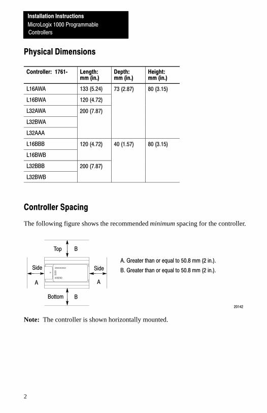
Physical Dimensions
Controller: 1761� Length:mm (in.)
Depth:mm (in.)
Height:mm (in.)
L16AWA 133 (5.24) 73 (2.87) 80 (3.15)
L16BWA 120 (4.72)
( ) ( )
L32AWA 200 (7.87)
L32BWA
( )
L32AAA
L16BBB 120 (4.72) 40 (1.57) 80 (3.15)
L16BWB
( ) ( ) ( )
L32BBB 200 (7.87)
L32BWB
( )
Controller Spacing
The following figure shows the recommended minimum spacing for the controller.
20142
B
A
A. Greater than or equal to 50.8 mm (2 in.).
B. Greater than or equal to 50.8 mm (2 in.).
B
A
Top
Bottom
SideSide
Note: The controller is shown horizontally mounted.

Installation Instructions
MicroLogix 1000 Programmable
Controllers
3
Mounting Your Controller Horizontally
The controller should be mounted horizontally within an enclosure using either theDIN rail or mounting screw option. Use the mounting template from the front ofthis document to help you space and mount the controller properly.
!ATTENTION: Be careful of metal chips when drilling mounting holesfor your controller. Drilled fragments that fall into the controller couldcause damage. Do not drill holes above a mounted controller if theprotective wrap is removed.
Using a DIN Rail
To install your controller on the DIN rail:1. Mount your DIN rail. (Make sure that the
placement of the controller on the DIN railmeets the recommended spacingrequirements. Refer to the mountingtemplate from the front of this document.)
3. While pressing the controller against therail, snap the controller into position.
4. Leave the protective wrap attached until youare finished wiring the controller.
2. Hook the top slot over the DIN rail.
20146
Side View
DIN Rail
Protective Wrap
MountingTemplate
To remove your controller from the DIN rail:
2. Holding the controller, pry downward onthe latch until the controller is releasedfrom the DIN rail.
1. Place a screwdriver in the DIN rail latch atthe bottom of the controller.
Side View
DIN Rail
20147
Installation Instructions
MicroLogix 1000 Programmable
Controllers
4
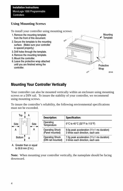
Using Mounting Screws
To install your controller using mounting screws:
2. Secure the template to the mountingsurface. (Make sure your controlleris spaced properly.)
1. Remove the mounting templatefrom the front of this document.
5. Mount the controller.
20145
4. Remove the mounting template.3. Drill holes through the template.
6. Leave the protective wrap attacheduntil you are finished wiring thecontroller.
MountingTemplate
ProtectiveWrap
Mounting Your Controller Vertically
Your controller can also be mounted vertically within an enclosure using mountingscrews or a DIN rail. To insure the stability of your controller, we recommendusing mounting screws.
To insure the controller’s reliability, the following environmental specificationsmust not be exceeded.
Description: Specification:
OperatingTemperature
0°C to 45°C (32°F to 113°F)
Operating Shock (Panel mounted)
9.0g peak acceleration (11±1 ms duration)3 times each direction, each axis
Operating Shock (DIN rail mounted)
7.0g peak acceleration (11±1 ms duration) 3 times each direction, each axis
Note: When mounting your controller vertically, the nameplate should be facingdownward.
A
A
A
A
Top
Bottom
SideSide
A. Greater than or equal to 50.8 mm (2 in.).
Installation Instructions
MicroLogix 1000 Programmable
Controllers
5
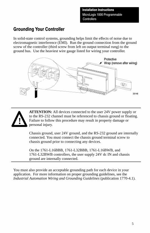
Grounding Your Controller
In solid-state control systems, grounding helps limit the effects of noise due toelectromagnetic interference (EMI). Run the ground connection from the groundscrew of the controller (third screw from left on output terminal rung) to theground bus. Use the heaviest wire gauge listed for wiring your controller.
20148
ProtectiveWrap (remove after wiring)
!ATTENTION: All devices connected to the user 24V power supply orto the RS-232 channel must be referenced to chassis ground or floating.Failure to follow this procedure may result in property damage orpersonal injury.
Chassis ground, user 24V ground, and the RS-232 ground are internallyconnected. You must connect the chassis ground terminal screw tochassis ground prior to connecting any devices.
On the 1761-L16BBB, 1761-L32BBB, 1761-L16BWB, and1761-L32BWB controllers, the user supply 24V dc IN and chassisground are internally connected.
You must also provide an acceptable grounding path for each device in yourapplication. For more information on proper grounding guidelines, see theIndustrial Automation Wiring and Grounding Guidelines (publication 1770-4.1).

Installation Instructions
MicroLogix 1000 Programmable
Controllers
6
Sinking and Sourcing
Type: Definition:
Sinking InputThe input energizes when high�level voltage is applied to theinput terminal (active high).
Sourcing InputThe input energizes when low�level voltage is applied to the inputterminal (active low).
Wiring Your Controller
Wire Type: Wire Size: (2 wire maximum per terminal screw)
Solid #14 to #22 AWG
Stranded #16 to #22 AWG
Important: The diameter of the terminal screw head is 5.5 mm (0.220 in.). Theinput and output terminals of the MicroLogix 1000 controller aredesigned for the following spade lugs:
Call�out Dimension
C 6.35 mm (0.250 in.)
E 10.95 mm (0.431 in.) maximum
L 14.63 mm (0.576 in.) maximum
W 6.35 mm (0.250 in.)
X 3.56 mm (0.140 in.)
C+X 9.91 mm (0.390 in.) maximum
We recommend using either of these AMP spade lugs: part number53120-1, if using 22–16 AWG, or part number 53123-1, if using16–14 AWG.
Installation Instructions
MicroLogix 1000 Programmable
Controllers
7
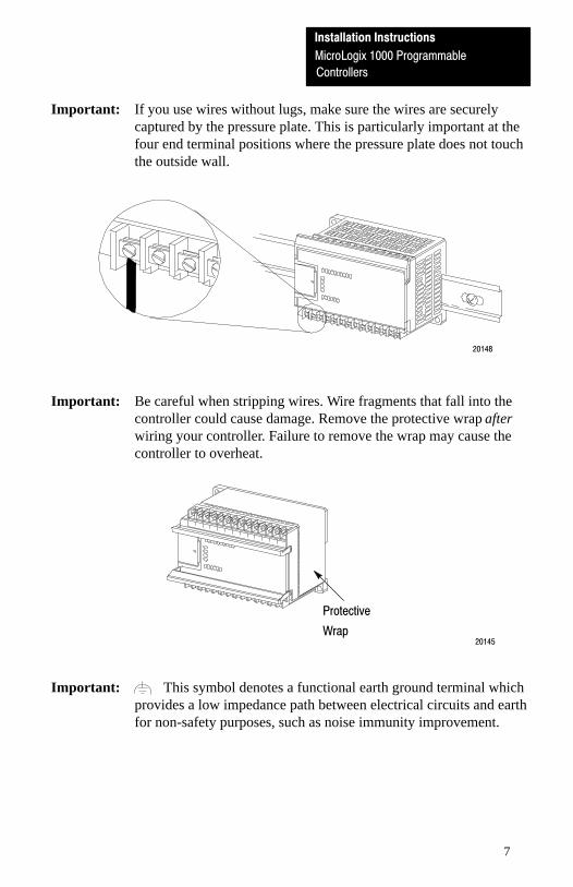
Important: If you use wires without lugs, make sure the wires are securelycaptured by the pressure plate. This is particularly important at thefour end terminal positions where the pressure plate does not touchthe outside wall.
20148
Important: Be careful when stripping wires. Wire fragments that fall into thecontroller could cause damage. Remove the protective wrap afterwiring your controller. Failure to remove the wrap may cause thecontroller to overheat.
20145
Protective
Wrap
Important: This symbol denotes a functional earth ground terminal whichprovides a low impedance path between electrical circuits and earthfor non-safety purposes, such as noise immunity improvement.

Installation Instructions
MicroLogix 1000 Programmable
Controllers
8
General Specifications
Description: Specification: 1761�L
16AWA 16BWA 32AWA 32BWA 32AAA 16BBB 16BWB 32BBB 32BWB
Memory Size andType
1 K EEPROM (approximately 737 instruction words: 437 data words)
Power SupplyVoltage
85-264V ac 20.4-26.4V dc
PowerSupply
120V ac 12 VA 19 VA 16 VA 24 VA 16 VA Not ApplicableSupplyUsage 240V ac 18 VA 26 VA 22 VA 30 VA 22 VAUsage
24V dc Not Applicable 5 VA 5 VA 7 VA 7 VA
24V dc SensorPower (V dc at mA)
NotApplicable
200 mA NotApplicable
200 mA Not Applicable
Max CapacitiveLoad (User 24V dc)
NotApplicable
200 µF NotApplicable
200 µF
Power Cycles 50,000 minimum
Operating Temp. 0° C to 55° C (32° F to 131° F) for horizontal mounting0° C to 45° C (32° F to 113° F) for vertical mounting
Storage Temp. -40° C to 85° C (-40° F to 185° F)
Operating Humidity 5 to 95% noncondensing
Vibration Operating: 5 Hz to 2k Hz, 0.381 mm (0.015 in.) peak to peak/2.5g panel mounted,➀ 1hr per axis
Non�operating: 5 Hz to 2k Hz, 0.762 mm (0.030 in.) peak to peak/5g, 1hr per axis
Shock Operating: 10g peak acceleration (7.5g DIN rail mounted)➁ (11±1 ms duration) 3 times each
direction, each axis
Non�operating: 20g peak acceleration (11±1 ms duration), 3 times each direction, each axis
AgencyCertification
• CSA certified• UL listed• CE marked for all applicable directives. (Refer to the MicroLogix� 1000 Programmable
Controllers User Manual [publication number 1761�6.3] for more information regardingcompliance to European Union directives.)
Terminal ScrewTorque
0.9 N�m maximum (8.0 in.�lbs)
ElectrostaticDischarge
IEC801�2 @ 8K V
RadiatedSusceptibility
IEC801�3 @ 10 V/m, 27 MHz - 1000 MHz except for 3V/m, 87 MHz - 108 MHz, 174 MHz - 230 MHz, and 470 MHz - 790 MHz
Fast Transient IEC801�4 @ 2K V Power Supply, 1K V I/O
Isolation 1500V ac
➀ DIN rail mounted controller is 1g.
➁ Relays are derated an additional 2.5g on 32 pt. controllers.
9
Automates programmables MicroLogixTM 1000(Réf. 1761–L16AWA, –L16BWA, –L32AWA, –L32BWA,
–L16BBB, –L16BWB, –L32BBB, –L32BWB, –L32AAA)
Instructions d’installation
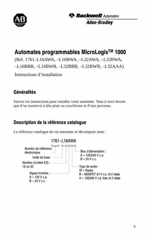
Généralités
Suivez ces instructions pour installer votre automate. Vous n’avez besoin que d’un tournevis à tête plate ou cruciforme et d’une perceuse.
Description de la référence catalogue
La référence catalogue de cet automate se décompose ainsi :
1761-L16AWA
Numéro de référence électronique
Unité de base
Nombre d'unités E/S :16 ou 32
Signal d'entrée :A = 120 V c.a.B = 24 V c.c.
Bloc d'alimentation :A = 120/240 V c.a.B = 24 V c.c.
Type de sortie :W = RelaisB = MOSFET 24 V c.c. et 2 relaisA = 120/240 V c.a. triac et 2 relais
Automates programmablesMicroLogix� 1000
Instructions d'installationInstructions d'installation
Automates programmables
MicroLogix 1000
10
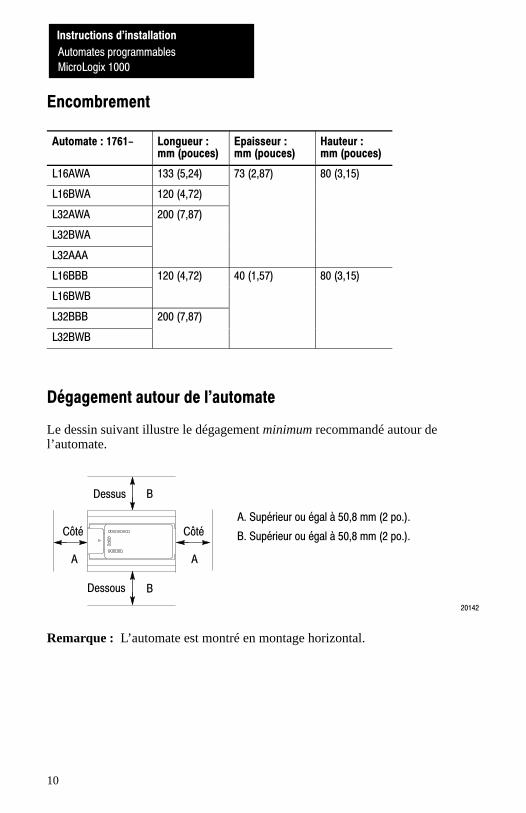
Encombrement
Automate : 1761- Longueur :mm (pouces)
Epaisseur :mm (pouces)
Hauteur :mm (pouces)
L16AWA 133 (5,24) 73 (2,87) 80 (3,15)
L16BWA 120 (4,72)
L32AWA 200 (7,87)
L32BWA
L32AAA
L16BBB 120 (4,72) 40 (1,57) 80 (3,15)
L16BWB
L32BBB 200 (7,87)
L32BWB
Dégagement autour de l'automate
Le dessin suivant illustre le dégagement minimum recommandé autour del’automate.
20142
B
A
A. Supérieur ou égal à 50,8 mm (2 po.).
B. Supérieur ou égal à 50,8 mm (2 po.).
B
A
Dessus
Dessous
CôtéCôté
Remarque : L’automate est montré en montage horizontal.
Instructions d'installation
Automates programmables
MicroLogix 1000
Instructions d'installation
Automates programmables
MicroLogix 1000
11
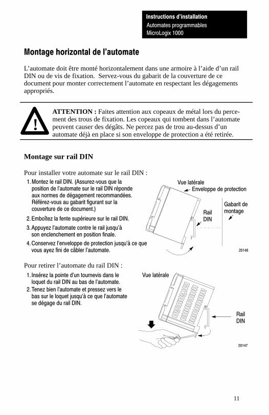
Montage horizontal de l'automate
L’automate doit être monté horizontalement dans une armoire à l’aide d’un railDIN ou de vis de fixation. Servez-vous du gabarit de la couverture de cedocument pour monter correctement l’automate en respectant les dégagementsappropriés.
!ATTENTION : Faites attention aux copeaux de métal lors du perce-ment des trous de fixation. Les copeaux qui tombent dans l’automatepeuvent causer des dégâts. Ne percez pas de trou au-dessus d’unautomate déjà en place si son enveloppe de protection a été retirée.
Montage sur rail DIN
Pour installer votre automate sur le rail DIN :1. Montez le rail DIN. (Assurez�vous que la
position de l'automate sur le rail DIN répondeaux normes de dégagement recommandées.Référez�vous au gabarit figurant sur lacouverture de ce document.)
3. Appuyez l'automate contre le rail jusqu'àson enclenchement en position finale.
4. Conservez l'enveloppe de protection jusqu'à ce quevous ayez fini de câbler l'automate.
2. Emboîtez la fente supérieure sur le rail DIN.
20146
Vue latérale
RailDIN
Enveloppe de protection
Gabarit demontage
Pour retirer l’automate du rail DIN :
2. Tenez bien l'automate et pressez vers lebas sur le loquet jusqu'à ce que l'automatese dégage du rail DIN.
1. Insérez la pointe d'un tournevis dans leloquet du rail DIN au bas de l'automate.
Vue latérale
RailDIN
20147
Automates programmablesMicroLogix� 1000
Instructions d'installationInstructions d'installation
Automates programmables
MicroLogix 1000
12
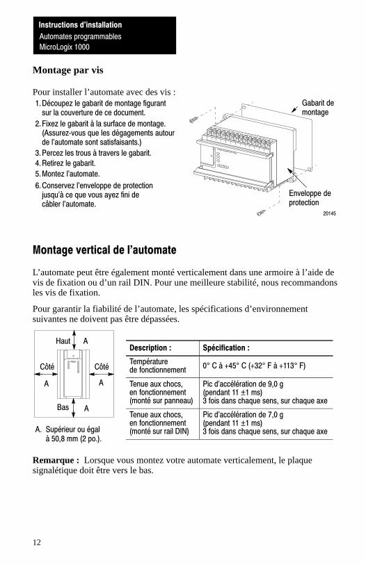
Montage par vis
Pour installer l’automate avec des vis :
2. Fixez le gabarit à la surface de montage.(Assurez�vous que les dégagements autourde l'automate sont satisfaisants.)
1. Découpez le gabarit de montage figurantsur la couverture de ce document.
5. Montez l'automate.
20145
4. Retirez le gabarit.3. Percez les trous à travers le gabarit.
6. Conservez l'enveloppe de protectionjusqu'à ce que vous ayez fini decâbler l'automate.
Gabarit demontage
Enveloppe deprotection
Montage vertical de l'automate
L’automate peut être également monté verticalement dans une armoire à l’aide devis de fixation ou d’un rail DIN. Pour une meilleure stabilité, nous recommandonsles vis de fixation.
Pour garantir la fiabilité de l’automate, les spécifications d’environnementsuivantes ne doivent pas être dépassées.
Description : Spécification :
Températurede fonctionnement
0° C à +45° C (+32° F à +113° F)
Tenue aux chocs, en fonctionnement(monté sur panneau)
Pic d'accélération de 9,0 g(pendant 11 ±1 ms) 3 fois dans chaque sens, sur chaque axe
Tenue aux chocs, en fonctionnement(monté sur rail DIN)
Pic d'accélération de 7,0 g(pendant 11 ±1 ms)3 fois dans chaque sens, sur chaque axe
Remarque : Lorsque vous montez votre automate verticalement, le plaquesignalétique doit être vers le bas.
A
A
A
A
Haut
Bas
CôtéCôté
A. Supérieur ou égal à 50,8 mm (2 po.).

Instructions d'installation
Automates programmables
MicroLogix 1000
13
Mise de l'automate à la terre
Dans les systèmes à logique statique, la mise à la terre limite les perturbationsdues aux interférences électromagnétiques (EMI). Tirez le câble de connexion à labarette de masse à partir de la vis de prise de terre (troisième vis en partant de lagauche sur la rangée des bornes de sortie). Parmi les câbles listés, chosissez celuide la plus grande section pour votre automate.
20148
Enveloppe protectrice (àenlever après câblage)
!ATTENTION : Tous les appareils connectés au bloc d’alimentationutilisateur de 24 V ou au canal RS–232 doivent être reliés à la masse duchâssis ou flottants. Le non-respect de cette procédure peut aboutir à desdégâts de matériel ou à des blessures de personnel.
La masse du châssis, la masse utilisateur de 24 V et celle du connecteurRS–232 sont connectées intérieurement. Connectez à la masse duchâssis la vis de prise de terre située sur le bornier avant de connecter lesautres appareils.
Sur les automates 1761-L16BBB, 1761-L32BBB, 1761-L16BWB et1761-L32BWB, l’alimentation utilisateur 24 V c.c. IN et la masse duchâssis sont connectés intérieurement.
Pour chaque appareil de votre application, vous devez assurer une connexion à la terre acceptable. Pour de plus amples informations sur les directives d’une mise à la terre correcte, consultez la publication 1770-4.1FR, Câblage des automates programmables Allen-Bradley et directives de mise à la terre.
Automates programmablesMicroLogix� 1000
Instructions d'installationInstructions d'installation
Automates programmables
MicroLogix 1000
14
Absorption et émission
Type : Définition :
Entrée d'absorption (Sink) L'entrée est alimentée lorsqu'une tension de niveauélevé est appliquée à la borne d'entrée (haut actif).
Entrée d'émission (Source) L'entrée est alimentée lorsqu'une tension de niveaufaible est appliquée à la borne d'entrée (bas actif).
Câblage de votre automate
Type de câble : Section : (2 fils maximum par borne à vis)
Fil unique Calibre AWG 14 à 22 (2,08 à 0,326 mm2)
Fil à brins Calibre AWG 16 à 22 (1,31 à 0,326 mm2)
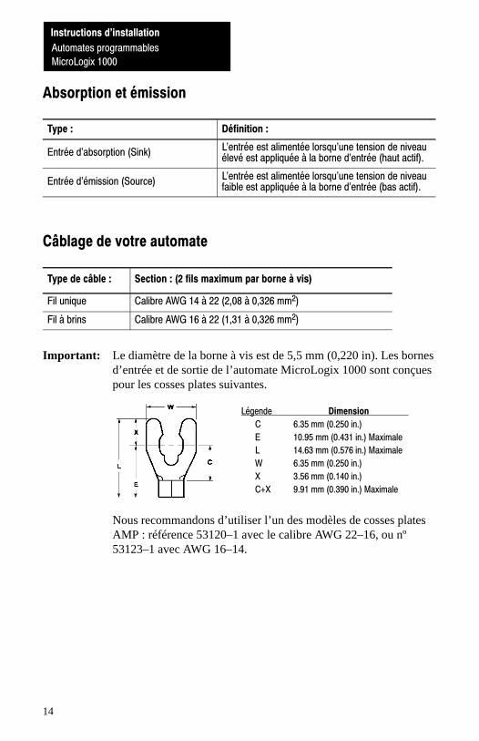
Important: Le diamètre de la borne à vis est de 5,5 mm (0,220 in). Les bornesd’entrée et de sortie de l’automate MicroLogix 1000 sont conçuespour les cosses plates suivantes.
Légende Dimension
C 6.35 mm (0.250 in.)
E 10.95 mm (0.431 in.) Maximale
L 14.63 mm (0.576 in.) Maximale
W 6.35 mm (0.250 in.)
X 3.56 mm (0.140 in.)
C+X 9.91 mm (0.390 in.) Maximale
Nous recommandons d’utiliser l’un des modèles de cosses platesAMP : référence 53120–1 avec le calibre AWG 22–16, ou nº53123–1 avec AWG 16–14.
Instructions d'installation
Automates programmables
MicroLogix 1000
15
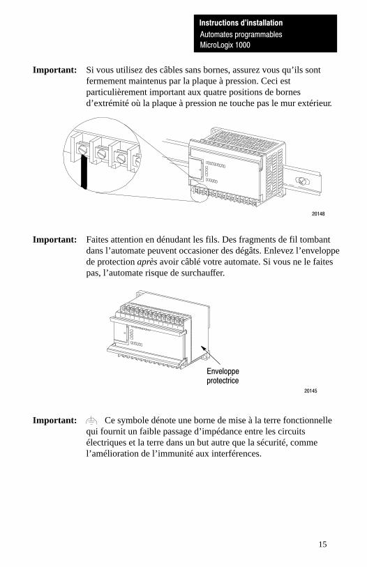
Important: Si vous utilisez des câbles sans bornes, assurez vous qu’ils sontfermement maintenus par la plaque à pression. Ceci estparticulièrement important aux quatre positions de bornesd’extrémité où la plaque à pression ne touche pas le mur extérieur.
20148
Important: Faites attention en dénudant les fils. Des fragments de fil tombantdans l’automate peuvent occasioner des dégâts. Enlevez l’enveloppede protection après avoir câblé votre automate. Si vous ne le faitespas, l’automate risque de surchauffer.
20145
Enveloppeprotectrice
Important: Ce symbole dénote une borne de mise à la terre fonctionnellequi fournit un faible passage d’impédance entre les circuitsélectriques et la terre dans un but autre que la sécurité, commel’amélioration de l’immunité aux interférences.

Automates programmablesMicroLogix� 1000
Instructions d'installationInstructions d'installation
Automates programmables
MicroLogix 1000
16
Spécifications générales
Description : Spécification : 1761�Lp
16AWA 16BWA 32AWA 32BWA 32AAA 16BBB 16BWB 32BBB 32BWB
Taille/type mémoire 1 K EEPROM (environ 737 mots instruction : 437 mots de données)
Tension du blocd'alimentation
85-264 V c.a. 20,4-26,4 V c.c.
Alim.utilisée
120 V c.a. 12 VA 19 VA 16 VA 24 VA 16 VA Sans objetutilisée
240 V c.a. 18 VA 26 VA 22 VA 30 VA 22 VA
24 V c.c. Sans objet 5 VA 5 VA 7 VA 7 VA
Alim. capteurs 24 Vc.c. (V c.c. à mA)
Sansobjet
200 mA Sansobjet
200 mA Sans objet
Cap. charge max.(24 V c.c. utilisat.)
Sansobjet
200 µF Sansobjet
200 µF
Remises sous tens. 50 000 minimum
Temp. fonctionne. 0° C à 55° C (32° F à 131° F) pour montage horizontal0° C à 45° C (32° F à 113° F) pour montage vertical
Temp. stockage -40° C à 85° C (-40° F à 185° F)
Humidité ambiante 5 à 95 % sans condensation
Résistance auxvibrations
En service : 5 Hz à 2 kHz, 0,381 mm (0,015 po.) pic à pic, 2,5 g maximum en montage surpanneau➀ , 1 hr par axe
A l'arrêt : 5 Hz à 2 kHz, 0,762 mm (0,030 po.) pic à pic, 5 g maximum, 1 hr par axe
Tenue aux chocs En service : pic d`accélération de 10 g (monté sur rail DIN : 7,5 g)➁ (durée : 11±1 ms), 3 foisdans chaque sens, pour chaque axe
A l`arret : pic d`accélé.de 20 g (durée : 11±1 ms) 3 fois dans chaque sens, pour chaque axe
Homologations • Certifié CSA• Listé UL• Marqué CE pour toutes directives applicables (reportez�vous à la publication numéro
1761�6.3 MicroLogix� 1000 Programmable Controllers User Manual pour plus d'informationsur les directives de l'Union Européenee).
Couple des bornesà vis
0,9 N�m maximum (8,0 pouces par livre)
Déchargeélectrostatique
IEC801�2 à 8K V
Sensibilité auxradiations
IEC801�3 à 10 V/m, 27 MHz - 1000 MHz 3V/m, 87 MHz - 108 MHz, 174 MHz - 230 MHz et 470 MHz - 790 MHz
Transitoire rapide IEC801�4 avec alimentation ded 2 kV, E/S de 1 kV
Isolation 1500 V c.a.
➀ Automate monté sur rail DIN : 1 g.➁ Les relais sont déclassés de 2,5 g supplémentaires sur les automates à 32 points.
Instructions d'installation
Automates programmables
MicroLogix 1000
17
Tableau de réglage
Anglais : Français :
NOT USED INUTILISE
Wiring Diagram Schéma de câblage
Input Voltage Range Plage de tension d'entrée
Output Voltage Range Plage de tension de sortie
OUT SORTIE
COM COM (Commun)
On Niveau haut
Off Niveau bas
Operating Range Plage de fonctionnement
Sinking Configuration Configuration en absorption
Sourcing Configuration Configuration en émission
Sinking Input Configuration Configuration des entrées d'absorption
Sourcing Input Configuration Configuration des entrées d'émission
Sourcing Outputs Sorties d'émission

Automates programmablesMicroLogix� 1000
Instructions d'installationInstructions d'installation
Automates programmables
MicroLogix 1000
18
Notes
Instructions d'installation
Automates programmablesMicroLogix 1000
19
Speicherprogrammierbare SteuerungenMicroLogix 1000(Bestell-Nr. 1761–L16AWA, –L16BWA, –L32AWA, –L32BWA,
–L16BBB, –L16BWB, –L32BBB, –L32BWB, –L32AAA)
Installationsanleitung
Überblick
Installieren Sie die Steuerung mit Hilfe dieser Installationsanleitung. Die einzigenWerkzeuge, die Sie hierzu benötigen, sind ein Flachkopf- oderKreuzschlitzschraubenzieher und eine Bohrmaschine.
Details der Bestellnummer
Die Bestellnummer der Steuerung setzt sich aus den folgenden Komponentenzusammen:
1761�L16AWA
Bulletinnummer
Grundeinheit
E/A�Anzahl der Ein�heit: 16 oder 32
Eingangssignal:A = 120 V ACB = 24 V DC
Netzteil:A = 120/240 V ACB = 24 V DC
Ausgangstyp:W = RelaisB = 24�V�DC�MOSFET und 2 RelaisA = 120/240 V AC Triac und 2 Relais
InstallationsanleitungSpeicherprogrammierbare SteuerungenMicroLogix 1000
20
Physikalische Abmessungen
Steuerung: 1761- Länge:in mm
Tiefe:in mm
Höhe:in mm
L16AWA 133 73 80
L16BWA 120
L32AWA 200
L32BWA
L32AAA
L16BBB 120 40 80
L16BWB
L32BBB 200
L32BWB
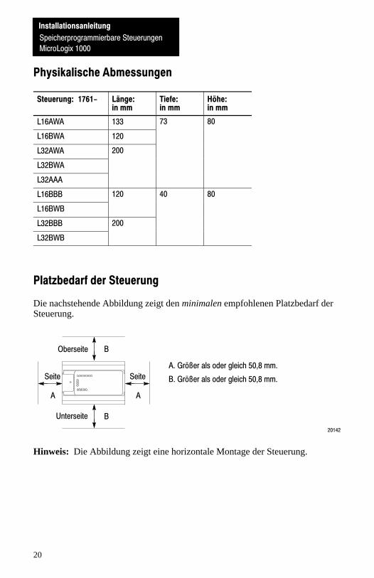
Platzbedarf der Steuerung
Die nachstehende Abbildung zeigt den minimalen empfohlenen Platzbedarf derSteuerung.
20142
B
A
A. Größer als oder gleich 50,8 mm.
B. Größer als oder gleich 50,8 mm.
B
A
Oberseite
Unterseite
SeiteSeite
Hinweis: Die Abbildung zeigt eine horizontale Montage der Steuerung.
InstallationsanleitungSpeicherprogrammierbare Steuerungen
MicroLogix 1000
Speicherprogrammierbare Steuerungen
InstallationsanleitungSpeicherprogrammierbare SteuerungenMicroLogix 1000
21
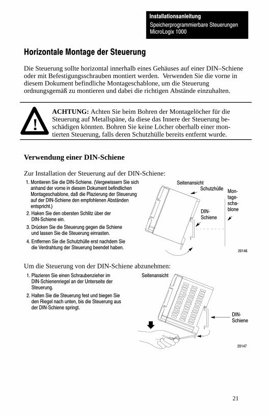
Horizontale Montage der Steuerung
Die Steuerung sollte horizontal innerhalb eines Gehäuses auf einer DIN–Schieneoder mit Befestigungsschrauben montiert werden. Verwenden Sie die vorne indiesem Dokument befindliche Montageschablone, um die Steuerungordnungsgemäß zu montieren und dabei die richtigen Abstände einzuhalten.
!ACHTUNG: Achten Sie beim Bohren der Montagelöcher für dieSteuerung auf Metallspäne, da diese das Innere der Steuerung be-schädigen könnten. Bohren Sie keine Löcher oberhalb einer mon-tierten Steuerung, falls deren Schutzhülle bereits entfernt wurde.
Verwendung einer DIN-Schiene
Zur Installation der Steuerung auf der DIN-Schiene:1. Montieren Sie die DIN�Schiene. (Vergewissern Sie sich
anhand der vorne in diesem Dokument befindlichenMontageschablone, daß die Plazierung der Steuerungauf der DIN�Schiene den empfohlenen Abständenentspricht.)
3. Drücken Sie die Steuerung gegen die Schieneund lassen Sie die Steuerung einrasten.
4. Entfernen Sie die Schutzhülle erst nachdem Siedie Verdrahtung der Steuerung beendet haben.
2. Haken Sie den obersten Schlitz über derDIN�Schiene ein.
20146
Seitenansicht
DIN�Schiene
Schutzhülle Mon�tage�scha�blone
Um die Steuerung von der DIN-Schiene abzunehmen:
2. Halten Sie die Steuerung fest und biegen Sieden Riegel nach unten, bis die Steuerung ausder DIN�Schiene springt.
1. Plazieren Sie einen Schraubenzieher imDIN�Schienenriegel an der Unterseite derSteuerung.
Seitenansicht
DIN�Schiene
20147
Speicherprogrammierbare Steuerungen
InstallationsanleitungSpeicherprogrammierbare SteuerungenMicroLogix 1000

InstallationsanleitungSpeicherprogrammierbare SteuerungenMicroLogix 1000
22
Verwendung von Befestigungsschrauben
Zur Installation der Steuerung mit Befestigungsschrauben:
2. Befestigen Sie die Schablone an derMontagefläche. (Stellen Sie sicher, daß dieentsprechenden Abstände eingehalten wurden.)
1. Nehmen Sie die vorne in diesem Dokumentbefindliche Montageschablone heraus.
5. Montieren Sie die Steuerung.
20145
4. Entfernen Sie die Montageschablone.
3. Bohren Sie die Löcher durch die Schablone.
6. Entfernen Sie die Schutzhülle erstnachdem Sie die Verdrahtung derSteuerung beendet haben.
Montage�schablone
Schutzhülle
Vertikale Montage der Steuerung
Die Steuerung kann auch vertikal innerhalb eines Gehäuses mit Befestigungs-schrauben oder auf einer DIN–Schiene montiert werden. Zur Gewährleistung derStabilität der Steuerung empfehlen wir die Verwendung von Befestigungs-schrauben.
Die folgenden Umgebungsspezifikationen dürfen nicht überschritten werden,damit die Zuverlässigkeit der Steuerung sichergestellt ist.
Beschreibung: Spezifikation:
Betriebstemperatur 0 °C bis 45 °C
Betriebsstoß(Paneelmontage)
9,0 g Spitzenbeschleunigung (11±1 ms Dauer)3mal jede Richtung, jede Achse
Betriebsstoß(Montage an einerDIN-Schiene)
7,0 g Spitzenbeschleunigung (11±1 ms Dauer)3mal jede Richtung, jede Achse
Hinweis: Bei einer vertikalen Montage der Steuerung sollte das Typenschild nachunten zeigen.
A
A
A
A
Oberseite
Unterseite
SeiteSeite
A. Größer als oder gleich50,8 mm
Speicherprogrammierbare Steuerungen
InstallationsanleitungSpeicherprogrammierbare SteuerungenMicroLogix 1000
23
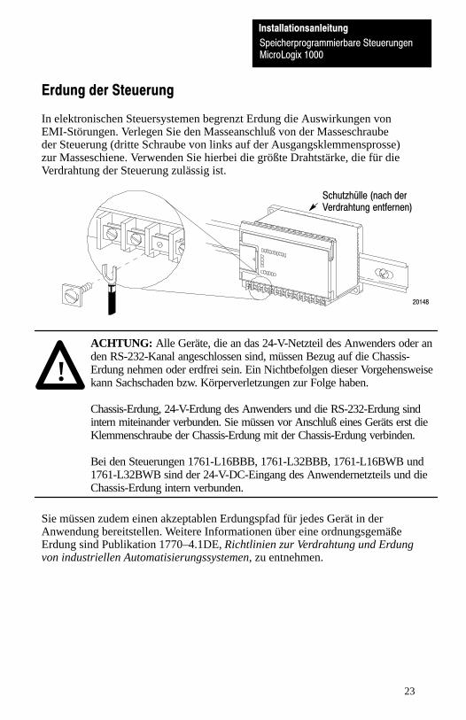
Erdung der Steuerung
In elektronischen Steuersystemen begrenzt Erdung die Auswirkungen vonEMI-Störungen. Verlegen Sie den Masseanschluß von der Masseschraubeder Steuerung (dritte Schraube von links auf der Ausgangsklemmensprosse)zur Masseschiene. Verwenden Sie hierbei die größte Drahtstärke, die für dieVerdrahtung der Steuerung zulässig ist.
20148
Schutzhülle (nach derVerdrahtung entfernen)
!ACHTUNG: Alle Geräte, die an das 24-V-Netzteil des Anwenders oder anden RS-232-Kanal angeschlossen sind, müssen Bezug auf die Chassis-Erdung nehmen oder erdfrei sein. Ein Nichtbefolgen dieser Vorgehensweisekann Sachschaden bzw. Körperverletzungen zur Folge haben.
Chassis-Erdung, 24-V-Erdung des Anwenders und die RS-232-Erdung sindintern miteinander verbunden. Sie müssen vor Anschluß eines Geräts erst dieKlemmenschraube der Chassis-Erdung mit der Chassis-Erdung verbinden.
Bei den Steuerungen 1761-L16BBB, 1761-L32BBB, 1761-L16BWB und1761-L32BWB sind der 24-V-DC-Eingang des Anwendernetzteils und dieChassis-Erdung intern verbunden.
Sie müssen zudem einen akzeptablen Erdungspfad für jedes Gerät in derAnwendung bereitstellen. Weitere Informationen über eine ordnungsgemäßeErdung sind Publikation 1770–4.1DE, Richtlinien zur Verdrahtung und Erdungvon industriellen Automatisierungssystemen, zu entnehmen.
Speicherprogrammierbare Steuerungen
InstallationsanleitungSpeicherprogrammierbare SteuerungenMicroLogix 1000
InstallationsanleitungSpeicherprogrammierbare SteuerungenMicroLogix 1000
24
Stromziehende und stromliefernde Eingänge
Typ: Definition:
Stromziehender EingangDer Eingang wird eingeschaltet, wenn Spannung andie Eingangsklemme angelegt wird (aktiv, H�Pegel).
Stromliefernder EingangDer Eingang wird eingeschaltet, wenn Nieder�spannung an die Eingangsklemme angelegt wird(aktiv, L�Pegel).
Verdrahtung der Steuerung
Drahttyp: Drahtgröße: (max. 2 Drähte je Klemmenschraube)
Eindrähtig AWG�Stärke 14 bis 22
Mehrdrähtig AWG�Stärke 16 bis 22
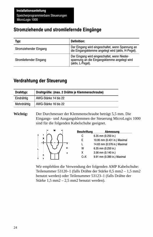
Wichtig: Der Durchmesser der Klemmenschraube beträgt 5,5 mm. DieEingangs– und Ausgangsklemmen der Steuerung MicroLogix 1000sind für die folgenden Kabelschuhe geeignet.
Beschriftung Abmessung C 6.35 mm (0.250 in.)
E 10.95 mm (0.431 in.) Maximal
L 14.63 mm (0.576 in.) Maximal
W 6.35 mm (0.250 in.)
X 3.56 mm (0.140 in.)
C+X 9.91 mm (0.390 in.) Maximal
Wir empfehlen die Verwendung der folgenden AMP Kabelschuhe:Teilenummer 53120–1 (falls Drähte der Stärke 0,5 mm2 – 1,5 mm2benutzt werden) oder Teilenummer 53123–1 (falls Drähte derStärke 1,5 mm2 – 2,5 mm2 benutzt werden).
Speicherprogrammierbare Steuerungen
InstallationsanleitungSpeicherprogrammierbare SteuerungenMicroLogix 1000
25
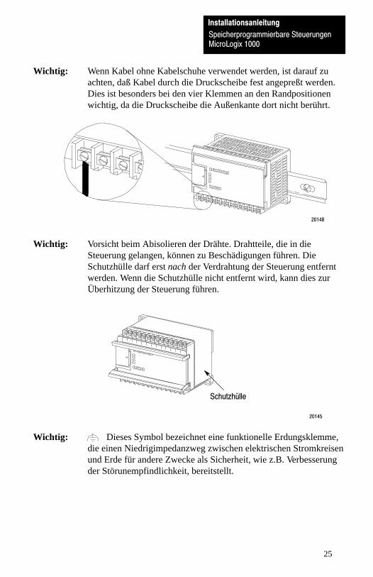
Wichtig: Wenn Kabel ohne Kabelschuhe verwendet werden, ist darauf zuachten, daß Kabel durch die Druckscheibe fest angepreßt werden.Dies ist besonders bei den vier Klemmen an den Randpositionenwichtig, da die Druckscheibe die Außenkante dort nicht berührt.
20148
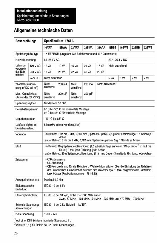
Wichtig: Vorsicht beim Abisolieren der Drähte. Drahtteile, die in dieSteuerung gelangen, können zu Beschädigungen führen. DieSchutzhülle darf erst nach der Verdrahtung der Steuerung entferntwerden. Wenn die Schutzhülle nicht entfernt wird, kann dies zurÜberhitzung der Steuerung führen.
20145
Schutzhülle
Wichtig: Dieses Symbol bezeichnet eine funktionelle Erdungsklemme,die einen Niedrigimpedanzweg zwischen elektrischen Stromkreisenund Erde für andere Zwecke als Sicherheit, wie z.B. Verbesserungder Störunempfindlichkeit, bereitstellt.
InstallationsanleitungSpeicherprogrammierbare SteuerungenMicroLogix 1000
26
Allgemeine technische Daten
Beschreibung: Spezifikation: 1761�L
16AWA 16BWA 32AWA 32BWA 32AAA 16BBB 16BWB 32BBB 32BWB
Speichergröße/�typ 1K EEPROM (ungefähr 737 Befehlsworte und 437 Datenworte)
Netzteilspannung 85-264 V AC 20,4-26,4 V DC
Leistungs�verbrauch
120 V AC 12 VA 19 VA 16 VA 24 VA 16 VA Nicht zutreffendverbrauchdes Netz�teils bei
240 V AC 18 VA 26 VA 22 VA 30 VA 22 VAteils bei
24 V DC Nicht zutreffend 5 VA 5 VA 7 VA 7 VA
24�V�DC�Sensorlei�stung (V DC bei mA)
Nichtzutreffend
200 mA Nichtzutreffend
200 mA Nicht zutreffend
Max. Kapazitivlast(Anwender, 24 V DC)
Nichtzutreffend
200 µF Nichtzutreffend
200 µF
Spannungszyklen Mindestens 50.000
Betriebstemperatur 0° C bis 55° C für horizontale Montage0° C bis 45° C für vertikale Montage
Lagertemperatur -40° C bis 85° C
Luftfeuchtigkeit imBetriebszustand
5 bis 95% (ohne Kondensation)
Vibration im Betrieb: 5 Hz bis 2 kHz, 0,381 mm (Spitze�zu�Spitze), 2,5 g bei Panelmontage➀ ; 1 Stunde jeAchse
außer Betrieb: 5 Hz bis 2 kHz, 0,762 mm (Spitze�zu�Spsitze), 5 g; 1 Stunde je Achse
Stoß im Betrieb: 10 g Spitzenbeschleunigung (7,5 g bei Montage auf einer DIN�Schiene)➁ (11±1 ms Dauer) 3 mal jede Richtung, jede Achse
außer Betrieb: 20 g Spitzenbeschleunigung (11±1 ms Dauer) 3 mal jede Richtung, jede Achse
Zulassung • CSA�Zulassung• UL�Auflistung• CE�Kennzeichnung für alle Richtlinien. (Weitere Informationen über die Einhaltung der Richtlinien
der Europäischen Gemeinschaft befinden sich im MicroLogix� 1000 Programmable ControllersUser Manual [Publikationsnummer 1761�6.3].)
Anzugsdrehmoment Maximal 0,9 Nm
ElektrostatischeEntladung
IEC801�2 bei 8 kV
Störempfindlichkeit IEC801�3 bei 10 V/m, 27 MHz - 1000 MHz außer 3V/m, 87 MHz - 108 MHz, 174 MHz - 230 MHz und 470 MHz - 790 MHz
Schnelle Spannungs�abweichungen
IEC801�4 bei 2�kV�Netzteil, 1�kV�E/A
Isolierspannung 1500 V AC
➀ Auf einer DIN�Schiene montierte Steuerung: 1 g➁ Weitere 2,5 g für Relais bei 32�Punkt�Steuerungen.

Speicherprogrammierbare Steuerungen
InstallationsanleitungSpeicherprogrammierbare SteuerungenMicroLogix 1000
27
Schlüsseltabelle
Englisch: Deutsch:
NOT USED NICHT BELEGT
Wiring Diagram Schaltplan
Input Voltage Range Eingangsspannungsbereich
Output Voltage Range Ausgangsspannungsbereich
OUT OUT
COM COM
On Ein
Off Aus
Operating Range Betriebsbereich
Sinking Configuration Stromziehende Konfiguration
Sourcing Configuration Stromliefernde Konfiguration
Sinking Input Configuration Stromziehende Eingangskonfiguration
Sourcing Input Configuration Stromliefernde Eingangskonfiguration
Sourcing Outputs Stromliefernde Ausgänge
InstallationsanleitungSpeicherprogrammierbare Steuerungen
MicroLogix 1000

InstallationsanleitungSpeicherprogrammierbare SteuerungenMicroLogix 1000
28
Notizien
InstallationsanleitungSpeicherprogrammierbare Steuerungen
MicroLogix 1000
29
Controllore programmabile MicroLogix 1000(No. cat. 1761–L16AWA, –L16BWA, –L32AWA, –L32BWA,
–L16BBB, –L16BWB, –L32BBB, –L32BWB, –L32AAA)
Istruzioni relative all’installazione
Generalità
Installate il controllore secondo le seguenti istruzioni istruzioni. Gli unici attrezzinecessari sono un cacciavite a testa piatta o a croce ed un trapano.
Dettagli sui numeri di catalogo
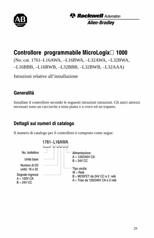
Il numero di catalogo per il controllore è composto come segue:
1761-L16AWA
No. bollettino
Unità base
Numero di I/Ounità: 16 o 32
Segnale ingressi:A = 120V CAB = 24V CC
Alimentazione:A = 120/240V CAB = 24V CC
Tipo uscita:W = RelèB = MOSFET da 24V CC e 2 relèA = Triac da 120/240V CA e 2 relè

Istruzioni relative all'installazione
Controllore programmabile
MicroLogix 1000
Istruzioni relative all'installazione
Controllore programmabile MicroLogix 1000
30
Dimensioni fisiche
Controllore: 1761- Lunghezza:mm (pollici)
Profondità:mm (pollici)
Altezza:mm (pollici)
L16AWA 133 (5,24) 73 (2,87) 80 (3,15)
L16BWA 120 (4,72)
L32AWA 200 (7,87)
L32BWA
L32AAA
L16BBB 120 (4,72) 40 (1,57) 80 (3,15)
L16BWB
L32BBB 200 (7,87)
L32BWB
Spaziatura del controllore
La figura seguente mostra la spaziatura minima consigliata per il controllore.
20142
B
A
A. Maggiore di o uguale a 50,8 mm (2 pollici).
B. Maggiore di o uguale a 50,8 mm (2 pollici).
B
A
Sopra
Sotto
LatoLato
Nota: il controllore viene illustrato orizzontalmente, montato.
Istruzioni relative all'installazione
Controllore programmabile
MicroLogix 1000
Istruzioni relative all'installazione
Controllore programmabile
MicroLogix 1000
31
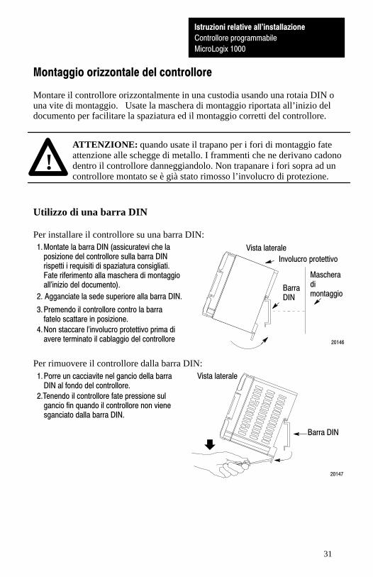
Montaggio orizzontale del controllore
Montare il controllore orizzontalmente in una custodia usando una rotaia DIN ouna vite di montaggio. Usate la maschera di montaggio riportata all’inizio deldocumento per facilitare la spaziatura ed il montaggio corretti del controllore.
!ATTENZIONE: quando usate il trapano per i fori di montaggio fateattenzione alle schegge di metallo. I frammenti che ne derivano cadonodentro il controllore danneggiandolo. Non trapanare i fori sopra ad uncontrollore montato se è già stato rimosso l’involucro di protezione.
Utilizzo di una barra DIN
Per installare il controllore su una barra DIN:1. Montate la barra DIN (assicuratevi che la
posizione del controllore sulla barra DINrispetti i requisiti di spaziatura consigliati.Fate riferimento alla maschera di montaggioall'inizio del documento).
3. Premendo il controllore contro la barrafatelo scattare in posizione.
4. Non staccare l'involucro protettivo prima diavere terminato il cablaggio del controllore
2. Agganciate la sede superiore alla barra DIN.
20146
Vista laterale
BarraDIN
Involucro protettivo
Mascheradimontaggio
Per rimuovere il controllore dalla barra DIN:
2.Tenendo il controllore fate pressione sulgancio fin quando il controllore non vienesganciato dalla barra DIN.
1. Porre un cacciavite nel gancio della barraDIN al fondo del controllore.
Vista laterale
Barra DIN
20147

Istruzioni relative all'installazione
Controllore programmabile
MicroLogix 1000
Istruzioni relative all'installazione
Controllore programmabile MicroLogix 1000
32
Utilizzo delle viti di montaggio
Per installare il controllore utilizzando le viti di montaggio:
2. Fissate la maschera alla superficie dimontaggio (assicuratevi che ilcontrollore abbia la spaziatura corretta).
1. Rimuovere la maschera di montaggio dallaparte anteriore di questo documento.
5. Montate il controllore.
20145
4. Rimuovete la maschera di montaggio.3. Effettuate i fori sulla maschera.
6. Non staccare l'involucro protettivoprima di avere terminato il cablaggiodel controllore.
Maschera dimontaggio
Involucroprotettivo
Montaggio verticale del controllore
È possibile montare il controllore anche verticalmente in una custodia usandodelle viti di montaggio o una rotaia DIN. Per garantire la stabilità del controllore,si consiglia di usare delle viti di montaggio.
Per garantire un’affidabilità del controllore, non oltrepassare le seguenticaratteristiche ambientali.
Descrizione: Caratteristica tecnica:
Temperatura difunzionamento
da 0°C a 45°C (da 32°F a 113°F)
Urto di funzionamento(montato su pannello)
9,0g di accelerazione di picco (durata di 11±1 ms)3 volte in ogni direzione, ogni asse
Urto di funzionamento(montato su rotaia DIN)
7,0g di accelerazione di picco (durata di 11±1 ms) 3 volte in ogni direzione, ogni asse
Nota: quando si monta il controllore verticalmente, la targhetta deve guardareverso il basso.
A
A
A
A
Partesuperiore
Parteinferiore
LatoLato
A. Maggiore o uguale a 50,8 mm (2 pollici)

Istruzioni relative all'installazione
Controllore programmabile
MicroLogix 1000
33
Messa a terra del controllore
Nei sistemi di controllo a stato solido, la messa a terra aiuta a limitare gli effettidei disturbi dovuti ad interferenze elettromagnetiche (EMI). Effettuate laconnessione a massa dalla vite di massa del controllore (la terza vite da sinistra sulramo del terminale di uscita) al bus di massa. Usate il filo di sezione più grandeammesso per il cablaggio del controllore.
20148
Involucro protettivo(rimuovere diopo ilcablaggio)
!ATTENZIONE: tutti i dispositivi connessi all’alimentazione da 24Vdell’utente o al canale RS–232 devono fare riferimento alla massa dellochassis o restare flottanti. In caso contrario si potrebbero riportare dannialla proprietà o lesioni alle persone.
La massa dello chassis, la massa utente da 24V e la massa dell’RS–232sono connesse internamente. Collegate la vite del terminale di massadello chassis alla massa dello stesso prima di collegare qualsiasidispositivo.
Nei controllori 1761–L16BBB, 1761–L32BBB, 1761–L16BWB e1761–L32BWB l’alimentazione d’ingresso cc da 24V dell’utente e lamassa dello chassis sono connesse internamente.
Dovete inoltre fornire un percorso di massa accettabile per ciascun dispositivopresente nell’applicazione. Per ulteriori informazioni sulle direttive per unacorretta messa a terra, consultate Direttive per il cablaggio e la messa a terra perautomazione industriale (pubblicazione 1770–4.1IT).
Istruzioni relative all'installazione
Controllore programmabile
MicroLogix 1000
Istruzioni relative all'installazione
Controllore programmabile MicroLogix 1000
34
Assorbimento e generazione di corrente
Tipo: Definizione:
Ingresso a comune negativo(assorbimento)
L'ingresso si attiva quando viene applicata una tensio�ne ad alto livello al terminale di ingresso (alto vero).
Ingresso a comune positivo(generazione)
L'ingresso si attiva quando viene applicata una tensio�ne a basso livello al terminale di ingresso (basso vero).
Cablaggio del controllore
Tipo di cavo: Dimensione cavo (max 2 cavi per vite del terminale).
Pieno Da 14 a 22 AWG (0,5 � 2,5 mm2)
A treccia Da 16 a 22 AWG (0,5 � 1,5 mm2)
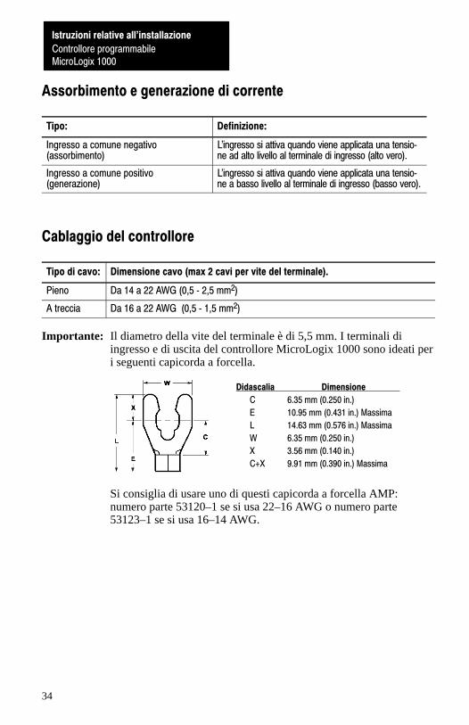
Importante: Il diametro della vite del terminale è di 5,5 mm. I terminali diingresso e di uscita del controllore MicroLogix 1000 sono ideati peri seguenti capicorda a forcella.
Didascalia Dimensione
C 6.35 mm (0.250 in.)
E 10.95 mm (0.431 in.) Massima
L 14.63 mm (0.576 in.) Massima
W 6.35 mm (0.250 in.)
X 3.56 mm (0.140 in.)
C+X 9.91 mm (0.390 in.) Massima
Si consiglia di usare uno di questi capicorda a forcella AMP:numero parte 53120–1 se si usa 22–16 AWG o numero parte53123–1 se si usa 16–14 AWG.
Istruzioni relative all'installazione
Controllore programmabile
MicroLogix 1000
35
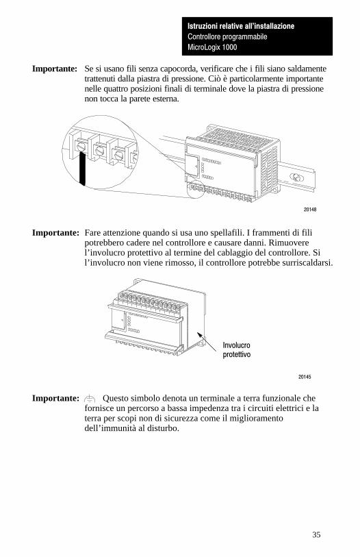
Importante: Se si usano fili senza capocorda, verificare che i fili siano saldamentetrattenuti dalla piastra di pressione. Ciò è particolarmente importantenelle quattro posizioni finali di terminale dove la piastra di pressionenon tocca la parete esterna.
20148
Importante: Fare attenzione quando si usa uno spellafili. I frammenti di filipotrebbero cadere nel controllore e causare danni. Rimuoverel’involucro protettivo al termine del cablaggio del controllore. Sil’involucro non viene rimosso, il controllore potrebbe surriscaldarsi.
20145
Involucroprotettivo
Importante: Questo simbolo denota un terminale a terra funzionale chefornisce un percorso a bassa impedenza tra i circuiti elettrici e laterra per scopi non di sicurezza come il miglioramentodell’immunità al disturbo.
Istruzioni relative all'installazione
Controllore programmabile
MicroLogix 1000
Istruzioni relative all'installazione
Controllore programmabile MicroLogix 1000
36
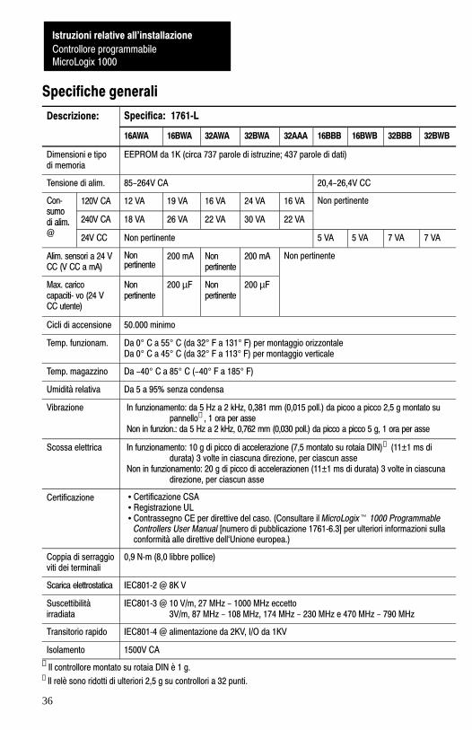
Specifiche generali
Descrizione: Specifica: 1761�L
16AWA 16BWA 32AWA 32BWA 32AAA 16BBB 16BWB 32BBB 32BWB
Dimensioni e tipodi memoria
EEPROM da 1K (circa 737 parole di istruzine; 437 parole di dati)
Tensione di alim. 85-264V CA 20,4-26,4V CC
Con�sumo
120V CA 12 VA 19 VA 16 VA 24 VA 16 VA Non pertinentesumodi alim.@
240V CA 18 VA 26 VA 22 VA 30 VA 22 VAdi alim.@
24V CC Non pertinente 5 VA 5 VA 7 VA 7 VA
Alim. sensori a 24 VCC (V CC a mA)
Nonpertinente
200 mA Nonpertinente
200 mA Non pertinente
Max. caricocapaciti� vo (24 VCC utente)
Nonpertinente
200 µF Nonpertinente
200 µF
Cicli di accensione 50.000 minimo
Temp. funzionam. Da 0° C a 55° C (da 32° F a 131° F) per montaggio orizzontaleDa 0° C a 45° C (da 32° F a 113° F) per montaggio verticale
Temp. magazzino Da -40° C a 85° C (-40° F a 185° F)
Umidità relativa Da 5 a 95% senza condensa
Vibrazione In funzionamento: da 5 Hz a 2 kHz, 0,381 mm (0,015 poll.) da picoo a picco 2,5 g montato supannello➀ , 1 ora per asse
Non in funzion.: da 5 Hz a 2 kHz, 0,762 mm (0,030 poll.) da picco a picco 5 g, 1 ora per asse
Scossa elettrica In funzionamento: 10 g di picco di accelerazione (7,5 montato su rotaia DIN)➁ (11±1 ms di durata) 3 volte in ciascuna direzione, per ciascun asse
Non in funzionamento: 20 g di picco di accelerazionen (11±1 ms di durata) 3 volte in ciascuna direzione, per ciascun asse
Certificazione • Certificazione CSA• Registrazione UL• Contrassegno CE per direttive del caso. (Consultare il MicroLogix� 1000 Programmable
Controllers User Manual [numero di pubblicazione 1761�6.3] per ulteriori informazioni sullaconformità alle direttive dell`Unione europea.)
Coppia di serraggioviti dei terminali
0,9 N�m (8,0 libbre pollice)
Scarica elettrostatica IEC801�2 @ 8K V
Suscettibilitàirradiata
IEC801�3 @ 10 V/m, 27 MHz - 1000 MHz eccetto 3V/m, 87 MHz - 108 MHz, 174 MHz - 230 MHz e 470 MHz - 790 MHz
Transitorio rapido IEC801�4 @ alimentazione da 2KV, I/O da 1KV
Isolamento 1500V CA
➀ Il controllore montato su rotaia DIN è 1 g.
➁ Il relè sono ridotti di ulteriori 2,5 g su controllori a 32 punti.

Istruzioni relative all'installazione
Controllore programmabile
MicroLogix 1000
37
Tabella chiave
Inglese: Lingua madre:
NOT USED NON UTILIZZATO
Wiring Diagram Schema di collegamento
Input Voltage Range Gamma di tensione ingressi
Output Voltage Range Gamma di tensione uscite
OUT OUT
COM COM
On Acceso
Off Spento
Operating Range Gamma di funzionamento
Sinking Configuration Configurazione di assorbimento
Sourcing Configuration Configurazione a generazione
Sinking Input Configuration Configurazione ingresso di assorbimento
Sourcing Input Configuration Configurazione ingresso a generazione
Sourcing Outputs Uscite a generazione
Istruzioni relative all'installazione
Controllore programmabile MicroLogix 1000

Istruzioni relative all'installazione
Controllore programmabile
MicroLogix 1000
Istruzioni relative all'installazione
Controllore programmabile MicroLogix 1000
38
Note
Istruzioni relative all'installazione
Controllore programmabile MicroLogix 1000
39
Controladores programables MicroLogix� 1000(No. de cat. 1761–L16AWA, –L16BWA, –L32AWA, –L32BWA,
–L16BBB, –L16BWB, –L32BBB, –L32BWB, –L32AAA)
Instrucciones para la instalación
Descripción general
Instale su controlador usando estas instrucciones de instalación. Las únicasherramientas que necesita son un destornillador plano o Phillips y un taladro.
Información sobre número de catálogo
El número de catálogo para el controlador consta de:
1761-L16AWA
Número de boletín
Unidad de base
Señal de entrada:A = 120 VCAB = 24 VCC
Fuente de alimentación:A = 120 VCAB = 24 VCCTipo de salida:W = ReléB = MOSFET 24 VCC y 2 relésA = Triac 120/240 VCA y 2 relés
Conteo unidad E/S:16 ó 32
Instrucciones para la instalación
Controladores programablesMicroLogix 1000
40
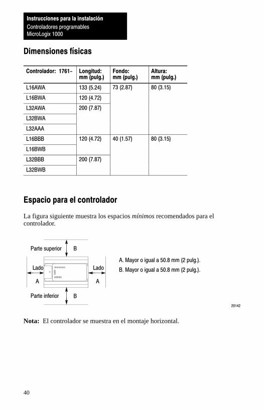
Dimensiones físicas
Controlador: 1761- Longitud:mm (pulg.)
Fondo:mm (pulg.)
Altura:mm (pulg.)
L16AWA 133 (5.24) 73 (2.87) 80 (3.15)
L16BWA 120 (4.72)
L32AWA 200 (7.87)
L32BWA
L32AAA
L16BBB 120 (4.72) 40 (1.57) 80 (3.15)
L16BWB
L32BBB 200 (7.87)
L32BWB
Espacio para el controlador
La figura siguiente muestra los espacios mínimos recomendados para elcontrolador.
20142
B
A
A. Mayor o igual a 50.8 mm (2 pulg.).
B. Mayor o igual a 50.8 mm (2 pulg.).
B
A
Parte superior
Parte inferior
LadoLado
Nota: El controlador se muestra en el montaje horizontal.
Instrucciones para la instalación
Controladores programablesMicroLogix 1000

Instrucciones para la instalación
Controladores programablesMicroLogix 1000
41
Montaje horizontal del controlador
El controlador se debe montar horizontalmente dentro de un envolvente usando unriel DIN o el tornillo de montaje opcional. Use la plantilla para instalación queproporcionamos al comienzo de este documento para obtener información sobrelos espacios y cómo instalar correctamente el controlador.
!ATENCION: Tenga cuidado con las rebabas metálicas cuando perforeagujeros para la instalación de su controlador. Los fragmentos que caendentro del controlador pueden dañarlo. No perfore agujeros encima deun controlador instalado si no tiene su cubierta protectora.
Uso de un riel DIN
Para instalar su controlador en el riel DIN:1. Instale su rail DIN. (Asegúrese de que la
ubicación del controlador en el riel DIN cumplacon los requisitos de espacio recomendados.Consulte la plantilla de instalación que seencuentra al comienzo de este documento.)
3. Mientras empuja el controlador contra elrail, encaje el controlador en su posición.
4. No quite la cubierta protectora hasta queacabe con el cableado del controlador.
2. Enganche la ranura superior sobre el rail DIN.
20146
Vista lateral
RielDIN
Cubiertaprotectora Plantilla
de insta�lación
Para extraer el controlador del riel DIN:
2. Sujetando el controlador aplique presiónhacia abajo sobre el seguro hasta que elcontrolador se desenganche del riel DIN.
1. Coloque un destornillador en el seguro delriel DIN en la parte inferior del controlador.
Vista lateral
RielDIN
20147
Instrucciones para la instalación
Controladores programables
MicroLogix 1000
Instrucciones para la instalación
Controladores programablesMicroLogix 1000
42
Uso de los tornillos para instalación
Para instalar su controlador usando los tornillos de instalación:
2. Asegure la plantilla a la superficie deinstalación. (Cerciórese de que sucontrolador tenga los espacios correctos).
1. Saque la plantilla de instalación de laparte frontal de este documento.
5. Instale el controlador.
20145
4. Saque la plantilla para instalación.3. Perfore agujeros a través de la plantilla.
6. No quite la cubierta protectora hasta que acabecon el cableado del controlador.
Cubiertaprotectora
Plantilla deinstalación
Montaje vertical del controlador
El controlador también se puede montar verticalmente dentro de un envolventeusando los tornillos de montaje o un riel DIN. Para asegurar la estabilidad delcontrolador, recomendamos el uso de los tornillos de montaje.
Para asegurar el funcionamiento seguro del controlador, es imprescindible noexceder las especificaciones ambientales siguientes.
Descripción: Especificación:
Temperatura defuncionamiento
0°C a 45°C (32°F a 113°F)
Impacto de funcio�namiento (montadoen panel)
aceleración pico de 9.0 g (durante 11±1 ms)3 veces en cada dirección, cada eje
Impacto de funcio�namiento (montadoen riel DIN)
aceleración pico de 7.0 g (durante 11±1 ms)3 veces en cada dirección, cada eje
Nota: Cuando el controlador se monta verticalmente, la placa de identificación sedebe orientar hacia abajo
A
A
A
A
Parte superior
Parteinferior
LadoLado
A. Mayor o igual que 50.8 mm (2 pulg.).
Instrucciones para la instalación
Controladores programablesMicroLogix 1000
43
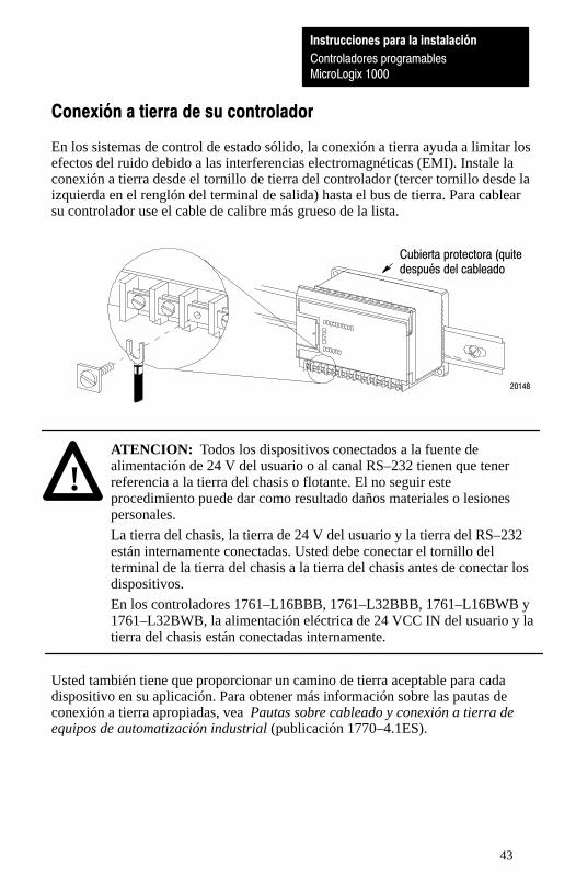
Conexión a tierra de su controlador
En los sistemas de control de estado sólido, la conexión a tierra ayuda a limitar losefectos del ruido debido a las interferencias electromagnéticas (EMI). Instale laconexión a tierra desde el tornillo de tierra del controlador (tercer tornillo desde laizquierda en el renglón del terminal de salida) hasta el bus de tierra. Para cablearsu controlador use el cable de calibre más grueso de la lista.
20148
Cubierta protectora (quitedespués del cableado
!ATENCION: Todos los dispositivos conectados a la fuente dealimentación de 24 V del usuario o al canal RS–232 tienen que tenerreferencia a la tierra del chasis o flotante. El no seguir esteprocedimiento puede dar como resultado daños materiales o lesionespersonales.
La tierra del chasis, la tierra de 24 V del usuario y la tierra del RS–232están internamente conectadas. Usted debe conectar el tornillo delterminal de la tierra del chasis a la tierra del chasis antes de conectar losdispositivos.
En los controladores 1761–L16BBB, 1761–L32BBB, 1761–L16BWB y1761–L32BWB, la alimentación eléctrica de 24 VCC IN del usuario y latierra del chasis están conectadas internamente.
Usted también tiene que proporcionar un camino de tierra aceptable para cadadispositivo en su aplicación. Para obtener más información sobre las pautas deconexión a tierra apropiadas, vea Pautas sobre cableado y conexión a tierra deequipos de automatización industrial (publicación 1770–4.1ES).

Instrucciones para la instalación
Controladores programablesMicroLogix 1000
44
Drenador y surtidor
Tipo: Definición:
Entrada drenador La entrada se activa cuando se aplica voltaje dealto nivel al terminal de entrada (activo alto).
Entrada surtidor La entrada se activa cuando se aplica voltaje debajo nivel al terminal de entrada (activo bajo).
Cableado de su controlador
Tipo cable Tam. de cable: (máximo 2 cables por tornillo de terminal)
Sólido #14 a #22 AWG
Trenzado #16 a #22 AWG
Importante: El diámetro del tornillo del terminal es 5.5 mm (0.220 pulg.). Losterminales de entrada y salida del controlador MicroLogix 1000 hansido diseñados para los siguientes terminales de horquilla.
Clave Dimensión
C 6.35 mm (0.250 in.)
E 10.95 mm (0.431 in.) Máximo
L 14.63 mm (0.576 in.) Máximo
W 6.35 mm (0.250 in.)
X 3.56 mm (0.140 in.)
C+X 9.91 mm (0.390 in.) Máximo
Recomendamos el uso de cualquiera de estos terminales dehorquilla AMP: número de parte 53120–1, si está usando 22–16AWG, o número de parte 53123–1 si está usando 16–14 AWG.

Instrucciones para la instalación
Controladores programablesMicroLogix 1000
45
Importante: Si usa cables sin conectores, asegúrese que los cableados estén biencapturados por la placa de presión. Esto es sumamente importante enlas cuatro posiciones de los terminales extremos donde la placa depresión no hace contacto con la pared exterior.
20148
Importante : Tenga sumo cuidado al desforrar los cables. Fragmentos del cableque caen en el controlador podrían causar daños. Quite la cubiertaprotectora después de cablear su controlador. El no quitar la cubiertaprotectora puede provocar el sobrecalentamiento del controlador.
20145Cubiertaprotectora
Importante: Este símbolo indica un terminal de tierra funcional queproporciona una ruta de impedancia baja entre los circuitoseléctricos y la conexión a tierra para fines que no son de seguridad,tales como mejoras de la inmunidad al ruido.
Instrucciones para la instalación
Controladores programablesMicroLogix 1000
46
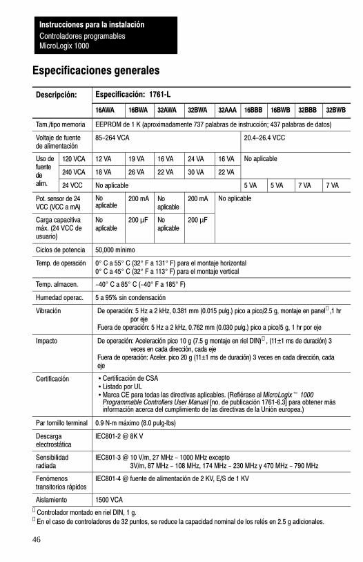
Especificaciones generales
Descripción: Especificación: 1761�L
16AWA 16BWA 32AWA 32BWA 32AAA 16BBB 16BWB 32BBB 32BWB
Tam./tipo memoria EEPROM de 1 K (aproximadamente 737 palabras de instrucción; 437 palabras de datos)
Voltaje de fuentede alimentación
85-264 VCA 20.4-26.4 VCC
Uso defuente
120 VCA 12 VA 19 VA 16 VA 24 VA 16 VA No aplicablefuentede 240 VCA 18 VA 26 VA 22 VA 30 VA 22 VA
p
dealim. 24 VCC No aplicable 5 VA 5 VA 7 VA 7 VA
Pot. sensor de 24VCC (VCC a mA)
Noaplicable
200 mA Noaplicable
200 mA No aplicable
Carga capacitivamáx. (24 VCC deusuario)
Noaplicable
200 µF Noaplicable
200 µF
Ciclos de potencia 50,000 mínimo
Temp. de operación 0° C a 55° C (32° F a 131° F) para el montaje horizontal0° C a 45° C (32° F a 113° F) para el montaje vertical
Temp. almacen. -40° C a 85° C (-40° F a 185° F)
Humedad operac. 5 a 95% sin condensación
Vibración De operación: 5 Hz a 2 kHz, 0.381 mm (0.015 pulg.) pico a pico/2.5 g, montaje en panel➀ ,1 hr por eje
Fuera de operación: 5 Hz a 2 kHz, 0.762 mm (0.030 pulg.) pico a pico/5 g, 1 hr por eje
Impacto De operación: Aceleración pico 10 g (7.5 g montaje en riel DIN)➁ , (11±1 ms de duración) 3 veces en cada dirección, cada eje
Fuera de operación: Aceler. pico 20 g (11±1 ms de duración) 3 veces en cada dirección, cadaeje
Certificación • Certificación de CSA• Listado por UL• Marca CE para todas las directivas aplicables. (Refiérase al MicroLogix� 1000
Programmable Controllers User Manual [no. de publicación 1761�6.3] para obtener másinformación acerca del cumplimiento de las directivas de la Unión europea.)
Par tornillo terminal 0.9 N�m máximo (8.0 pulg�lbs)
Descargaelectrostática
IEC801�2 @ 8K V
Sensibilidadradiada
IEC801�3 @ 10 V/m, 27 MHz - 1000 MHz excepto 3V/m, 87 MHz - 108 MHz, 174 MHz - 230 MHz y 470 MHz - 790 MHz
Fenómenostransitorios rápidos
IEC801�4 @ fuente de alimentación de 2 KV, E/S de 1 KV
Aislamiento 1500 VCA
➀ Controlador montado en riel DIN, 1 g.➁ En el caso de controladores de 32 puntos, se reduce la capacidad nominal de los relés en 2.5 g adicionales.
Instrucciones para la instalación
Controladores programablesMicroLogix 1000
47
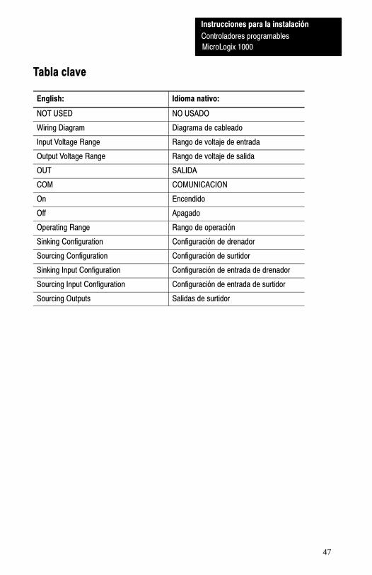
Tabla clave
English: Idioma nativo:
NOT USED NO USADO
Wiring Diagram Diagrama de cableado
Input Voltage Range Rango de voltaje de entrada
Output Voltage Range Rango de voltaje de salida
OUT SALIDA
COM COMUNICACION
On Encendido
Off Apagado
Operating Range Rango de operación
Sinking Configuration Configuración de drenador
Sourcing Configuration Configuración de surtidor
Sinking Input Configuration Configuración de entrada de drenador
Sourcing Input Configuration Configuración de entrada de surtidor
Sourcing Outputs Salidas de surtidor
Instrucciones para la instalación
Controladores programables
MicroLogix 1000

Instrucciones para la instalación
Controladores programablesMicroLogix 1000
48
Notas
Instrucciones para la instalación
Controladores programables
MicroLogix 1000

49
Wiring Diagrams, Input Voltage Ranges, and Output Voltage Ranges
1761–L16AWA Wiring Diagram
NOTUSED
NOTUSED
79-132V ac
L2/N
L1VACVDC O/0
VACVDC O/1
VACVDC O/2 O/3
VACVDC O/4L2/N O/5
85-264 VAC
CR CR
I/9I/0 I/1 I/2 I/3 I/4 I/5 I/6 I/7 I/8ACCOM
ACCOM
L1
CR
L2/N L1
VAC 1
VAC 1COM
VAC 2VAC 2COM
VDC 1VDC 1COM
VDC 2VDC 3COM
79-132V ac
VACVDC
CR
VDC 2COM
VDC 3
1761–L16AWA Input Voltage Range
0V ac 20V ac 132V ac79V ac
ÉÉÉÉÉÉÉÉÉÉÉÉÉÉÉÉÉÉÉÉÉÉÉÉ
On?Off
1761–L16AWA Output Voltage Range
0V dc 125V dc5V dc
ÉÉÉÉÉÉ
0V ac 264V ac5V ac
? Operating Range
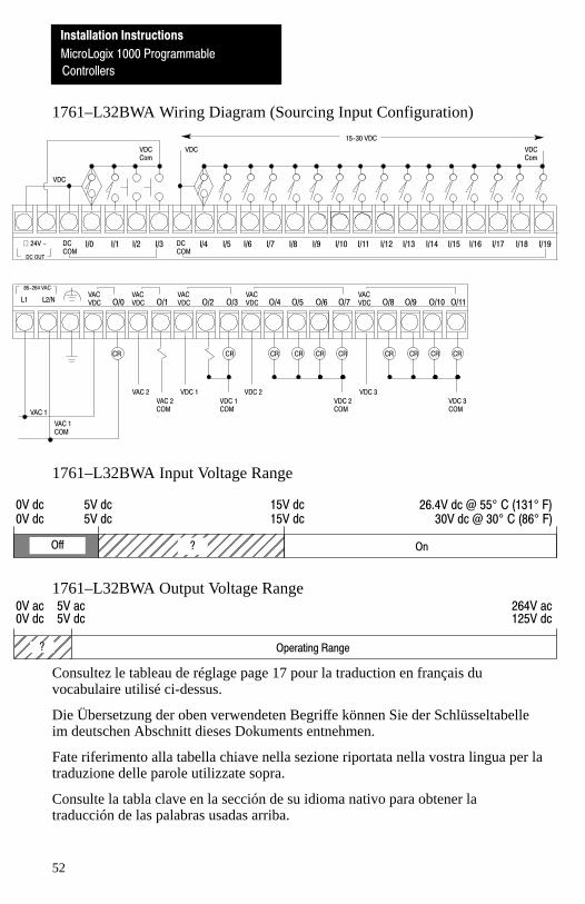
Consultez le tableau de réglage page 17 pour la traduction en français duvocabulaire utilisé ci-dessus.
Die Übersetzung der oben verwendeten Begriffe können Sie der Schlüsseltabelleim deutschen Abschnitt dieses Dokuments entnehmen.
Fate riferimento alla tabella chiave nella sezione riportata nella vostra lingua per latraduzione delle parole utilizzate sopra.
Consulte la tabla clave en la sección de su idioma nativo para obtener latraducción de las palabras usadas arriba.
Installation Instructions
MicroLogix 1000 Programmable
Controllers

Installation Instructions
MicroLogix 1000 Programmable
Controllers
50
1761–L16BWA Wiring Diagram (Sinking Input Configuration)
I/9
VDC Com
I/0 I/1 I/2 I/3 I/4 I/5 I/6 I/7 I/8
DC OUT
+ 24V - DCCOM
DCCOM
VDC VDC Com
VDC
15-30 VDC
L1VACVDC O/0
VACVDC O/1
VACVDC O/2 O/3
VACVDC O/4L2/N O/5
85-264 VAC
CR CR CR
VAC 2VAC 2COM
VDC 1VDC 1COM
VDC 2VDC 3COM
VACVDC
CR
VDC 2COM
VDC 3
VAC 1
VAC 1COM
1761–L16BWA Input Voltage Range
0V dc 5V dc30V dc @ 30° C (86° F)
15V dc
ÉÉÉÉÉÉÉÉÉÉÉÉÉÉÉÉÉÉ
On?Off
26.4V dc @ 55° C (131° F)0V dc 5V dc 15V dc
1761–L16BWA Output Voltage Range
0V dc 125V dc5V dc
ÉÉÉÉÉÉ
0V ac 264V ac5V ac
? Operating Range
Consultez le tableau de réglage page 17 pour la traduction en français duvocabulaire utilisé ci-dessus.
Die Übersetzung der oben verwendeten Begriffe können Sie der Schlüsseltabelleim deutschen Abschnitt dieses Dokuments entnehmen.
Fate riferimento alla tabella chiave nella sezione riportata nella vostra lingua per latraduzione delle parole utilizzate sopra.
Consulte la tabla clave en la sección de su idioma nativo para obtener latraducción de las palabras usadas arriba.

Installation Instructions
MicroLogix 1000 Programmable
Controllers
51
1761–L32AWA Wiring Diagram
NOTUSED
NOTUSED
79-132 VAC
L2/N
VACVDC O/0
VACVDC O/1
VACVDC O/2 O/3
VACVDC O/4 O/5 O/6
VACVDC O/8O/7 O/9 O/10 O/11
I/9 I/10ACCOM
I/0 I/1 I/2 I/3 I/4 I/5 I/6 I/7 I/8 I/11 I/12 I/13 I/14 I/15 I/16 I/17 I/18ACCOM
I/19
L1 L2/N L1
CR CR CRCR CR
VAC 2
VAC 2COM
VDC 1
VDC 1COM
VDC 2
VDC 2COM
CR CRCR CR
VDC 3
VDC 3COM
CR
79-132 VAC
L1 L2/N
85-264 VAC
VAC 1
VAC 1COM
1761–L32AWA Input Voltage Range
0V ac 20V ac 132V ac79V ac
ÉÉÉÉÉÉÉÉÉÉÉÉÉÉÉÉÉÉÉÉÉÉÉÉ
On?Off
1761–L32AWA Output Voltage Range
0V dc 125V dc5V dc
ÉÉÉÉÉÉ
0V ac 264V ac5V ac
? Operating Range
Consultez le tableau de réglage page 17 pour la traduction en français duvocabulaire utilisé ci-dessus.
Die Übersetzung der oben verwendeten Begriffe können Sie der Schlüsseltabelleim deutschen Abschnitt dieses Dokuments entnehmen.
Fate riferimento alla tabella chiave nella sezione riportata nella vostra lingua per latraduzione delle parole utilizzate sopra.
Consulte la tabla clave en la sección de su idioma nativo para obtener latraducción de las palabras usadas arriba.
Installation Instructions
MicroLogix 1000 Programmable
Controllers
52
1761–L32BWA Wiring Diagram (Sourcing Input Configuration)
I/9 I/10DCCOM
VDC Com
I/0 I/1 I/2 I/3 I/4 I/5 I/6 I/7 I/8 I/11 I/12 I/13 I/14 I/15 I/16 I/17 I/18 I/19DCCOM
VDC
VDC VDCCom
15-30 VDC
DC OUT
+ 24V -
VACVDC O/0
VACVDC O/1
VACVDC O/2 O/3
VACVDC O/4 O/5 O/6
VACVDC O/8O/7 O/9 O/10 O/11
CR CR CRCR CR
VAC 2
VAC 2COM
VDC 1
VDC 1COM
VDC 2
VDC 2COM
CR CRCR CR
VDC 3
VDC 3COM
CR
L1 L2/N
85-264 VAC
VAC 1
VAC 1COM
1761–L32BWA Input Voltage Range
0V dc 5V dc30V dc @ 30° C (86° F)
15V dc
ÉÉÉÉÉÉÉÉÉÉÉÉÉÉÉÉÉÉ
On?Off
26.4V dc @ 55° C (131° F)0V dc 5V dc 15V dc
1761–L32BWA Output Voltage Range
0V dc 125V dc5V dc
ÉÉÉÉÉÉ
0V ac 264V ac5V ac
? Operating Range
Consultez le tableau de réglage page 17 pour la traduction en français duvocabulaire utilisé ci-dessus.
Die Übersetzung der oben verwendeten Begriffe können Sie der Schlüsseltabelleim deutschen Abschnitt dieses Dokuments entnehmen.
Fate riferimento alla tabella chiave nella sezione riportata nella vostra lingua per latraduzione delle parole utilizzate sopra.
Consulte la tabla clave en la sección de su idioma nativo para obtener latraducción de las palabras usadas arriba.
Installation Instructions
MicroLogix 1000 Programmable
Controllers
53
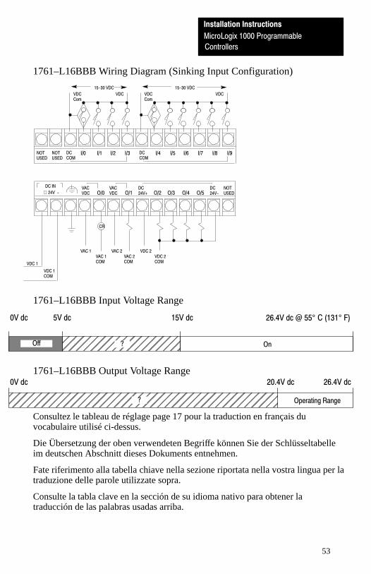
1761–L16BBB Wiring Diagram (Sinking Input Configuration)
NOTUSED
NOTUSED
VACVDC O/0
VACVDC O/1
DC24V+ O/2 O/3 O/4 O/5
I/9I/0 I/1 I/2 I/3 I/4 I/5 I/6 I/7 I/8DCCOM
DCCOM
DC24V-
NOTUSED
VDC Com
VDC
15-30 VDC
VDC Com
VDC
15-30 VDC
CR
VAC 1VAC 1COM
VAC 2VAC 2COM
VDC 2VDC 2COMVDC 1
VDC 1COM
DC IN
+ 24V -
1761–L16BBB Input Voltage Range
0V dc 5V dc 15V dc
ÉÉÉÉÉÉÉÉÉÉÉÉÉÉÉÉÉÉ
On?Off
26.4V dc @ 55° C (131° F)
1761–L16BBB Output Voltage Range0V dc 26.4V dc20.4V dc
ÉÉÉÉÉÉÉÉÉÉÉÉÉÉÉÉÉÉÉÉÉÉÉÉÉÉÉÉÉÉÉÉÉÉÉÉÉÉÉÉ
Operating Range?
Consultez le tableau de réglage page 17 pour la traduction en français duvocabulaire utilisé ci-dessus.
Die Übersetzung der oben verwendeten Begriffe können Sie der Schlüsseltabelleim deutschen Abschnitt dieses Dokuments entnehmen.
Fate riferimento alla tabella chiave nella sezione riportata nella vostra lingua per latraduzione delle parole utilizzate sopra.
Consulte la tabla clave en la sección de su idioma nativo para obtener latraducción de las palabras usadas arriba.
Installation Instructions
MicroLogix 1000 Programmable
Controllers
54
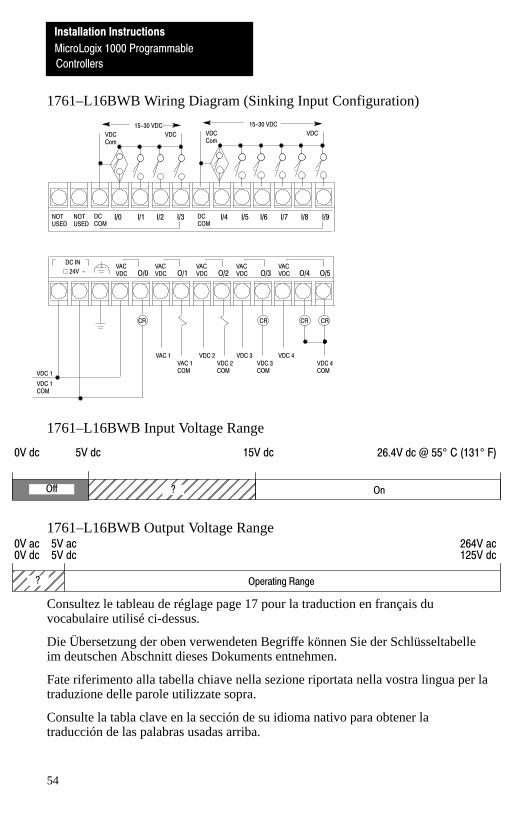
1761–L16BWB Wiring Diagram (Sinking Input Configuration)
DC IN
+ 24V -
NOTUSED
NOTUSED
VACVDC O/0
VACVDC O/1
VACVDC O/2 O/3
VACVDC O/4 O/5
I/9I/0 I/1 I/2 I/3 I/4 I/5 I/6 I/7 I/8DCCOM
DCCOM
VACVDC
VDC Com
VDC
15-30 VDC
VDC Com
VDC
15-30 VDC
CR CR CR
VAC 1VAC 1COM
VDC 2VDC 2COM
VDC 3VDC 4COM
CR
VDC 3COM
VDC 4
VDC 1
VDC 1COM
1761–L16BWB Input Voltage Range
0V dc 5V dc 15V dc
ÉÉÉÉÉÉÉÉÉÉÉÉÉÉÉÉÉÉ
On?Off
26.4V dc @ 55° C (131° F)
1761–L16BWB Output Voltage Range
0V dc 125V dc5V dcÉÉÉÉÉÉÉÉÉ
0V ac 264V ac5V ac
? Operating Range
Consultez le tableau de réglage page 17 pour la traduction en français duvocabulaire utilisé ci-dessus.
Die Übersetzung der oben verwendeten Begriffe können Sie der Schlüsseltabelleim deutschen Abschnitt dieses Dokuments entnehmen.
Fate riferimento alla tabella chiave nella sezione riportata nella vostra lingua per latraduzione delle parole utilizzate sopra.
Consulte la tabla clave en la sección de su idioma nativo para obtener latraducción de las palabras usadas arriba.
Installation Instructions
MicroLogix 1000 Programmable
Controllers
55
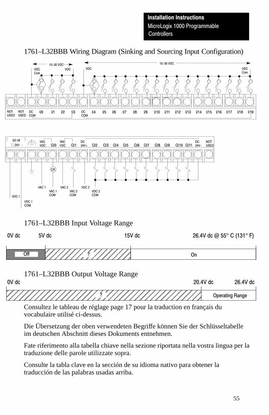
1761–L32BBB Wiring Diagram (Sinking and Sourcing Input Configuration)
NOTUSED
NOTUSED
VACVDC O/0
VACVDC O/1
DC24V+ O/2 O/3 O/4 O/5 O/6
DC24V-O/8O/7 O/9 O/10 O/11
I/9 I/10DCCOM
I/0 I/1 I/2 I/3 I/4 I/5 I/6 I/7 I/8 I/11 I/12 I/13 I/14 I/15 I/16 I/17 I/18DCCOM
I/19
NOTUSED
VDC Com
VDC
15-30 VDCVDC VDC
Com
15-30 VDC
CR
VAC 1VAC 1COM
VAC 2VAC 2COM
VDC 2VDC 2COMVDC 1
VDC 1COM
DC IN
+ 24V -
1761–L32BBB Input Voltage Range
0V dc 5V dc 15V dc
ÉÉÉÉÉÉÉÉÉÉÉÉÉÉÉÉÉÉ On?Off
26.4V dc @ 55° C (131° F)
1761–L32BBB Output Voltage Range0V dc 26.4V dc20.4V dcÉÉÉÉÉÉÉÉÉÉÉÉÉÉÉÉÉÉÉÉÉÉÉÉÉÉÉÉÉÉÉÉÉÉÉÉÉÉÉÉ Operating Range?
Consultez le tableau de réglage page 17 pour la traduction en français duvocabulaire utilisé ci-dessus.
Die Übersetzung der oben verwendeten Begriffe können Sie der Schlüsseltabelleim deutschen Abschnitt dieses Dokuments entnehmen.
Fate riferimento alla tabella chiave nella sezione riportata nella vostra lingua per latraduzione delle parole utilizzate sopra.
Consulte la tabla clave en la sección de su idioma nativo para obtener latraducción de las palabras usadas arriba.
Installation Instructions
MicroLogix 1000 Programmable
Controllers
56
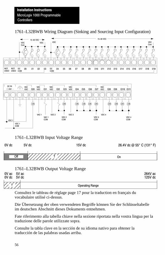
1761–L32BWB Wiring Diagram (Sinking and Sourcing Input Configuration)
NOTUSED
NOTUSED
VACVDC O/0
VACVDC O/1
VACVDC O/2 O/3
VACVDC O/4 O/5 O/6
VACVDC O/8O/7 O/9 O/10 O/11
I/9 I/10DCCOM
I/0 I/1 I/2 I/3 I/4 I/5 I/6 I/7 I/8 I/11 I/12 I/13 I/14 I/15 I/16 I/17 I/18DCCOM
I/19
VDC Com
VDC
15-30 VDC
CR CR CRCR CR
VAC 1
VAC 1COM
VDC 2
VDC 2COM
VDC 3
VDC 3COM
CR CRCR CR
VDC 4
VDC 4COM
CR
VDC 1
VDC 1COM
VDC VDCCom
15-30 VDC
DC IN
+ 24V -
1761–L32BWB Input Voltage Range
0V dc 5V dc 15V dc
ÉÉÉÉÉÉÉÉÉÉÉÉÉÉÉÉÉÉ
On?Off
26.4V dc @ 55° C (131° F)
1761–L32BWB Output Voltage Range
0V dc 125V dc5V dc
ÉÉÉÉÉÉ
0V ac 264V ac5V ac
? Operating Range
Consultez le tableau de réglage page 17 pour la traduction en français duvocabulaire utilisé ci-dessus.
Die Übersetzung der oben verwendeten Begriffe können Sie der Schlüsseltabelleim deutschen Abschnitt dieses Dokuments entnehmen.
Fate riferimento alla tabella chiave nella sezione riportata nella vostra lingua per latraduzione delle parole utilizzate sopra.
Consulte la tabla clave en la sección de su idioma nativo para obtener latraducción de las palabras usadas arriba.
Installation Instructions
MicroLogix 1000 Programmable
Controllers
57
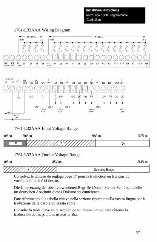
1761-L32AAA Wiring Diagram
NOTUSED
NOTUSED
79-132V ac
L2/N
VACVDC O/0
VACVDC O/1 VAC O/2 O/3 VAC O/4 O/5 O/6 VAC O/8O/7 O/9 O/10 O/11
I/9 I/10ACCOM
I/0 I/1 I/2 I/3 I/4 I/5 I/6 I/7 I/8 I/11 I/12 I/13 I/14 I/15 I/16 I/17 I/18ACCOM
I/19
L1 L2/N L1
CR CR CRCR CR
VAC 1
VAC 1COM
VAC 2
VAC 2COM
VAC 3
VAC 3COM
CR CRCR CR
VAC 4
VAC 4COM
CR
79-132V ac
L1 L2/N
85-264 VAC
VAC 0
VAC 0COM
1761-L32AAA Input Voltage Range
0V ac 20V ac 132V ac79V ac
ÉÉÉÉÉÉÉÉÉÉÉÉÉÉÉÉÉÉÉÉÉÉÉÉ
On?Off
1761-L32AAA Output Voltage Range
0V ac 264V ac85V ac
ÉÉÉÉÉÉÉÉÉÉÉÉÉÉÉÉÉÉ
? Operating Range
Consultez le tableau de réglage page 17 pour la traduction en français duvocabulaire utilisé ci-dessus.
Die Übersetzung der oben verwendeten Begriffe können Sie der Schlüsseltabelleim deutschen Abschnitt dieses Dokuments entnehmen.
Fate riferimento alla tabella chiave nella sezione riportata nella vostra lingua per latraduzione delle parole utilizzate sopra.
Consulte la tabla clave en la sección de su idioma nativo para obtener latraducción de las palabras usadas arriba.