micromanipulation system user manual
TRANSCRIPT
Visit Prior on the web at prior.comVERSION 03192015
Micromanipulation System User Manual
Sensapex Micromanipulation Systems Distributed by Prior Scientifc
Prior Scientific, LtdCambridge, UK
T. +44 (0) 1223 881711E. [email protected]
Prior Scientific, IncRockland, MA. USA
T. +1 781-878-8442E. [email protected]
Prior Scientific, GmbHJena, Germany
T. +49 (0) 3641 675 650E. [email protected]
Prior Scientific KKTokyo, Japan
T. +81-3-5652-8831E. [email protected]
Worldwide distribution

Sensapex SMX-series micromanipulation system
Operating manual
Rev. 2.11

Disclaimer
Best efforts have been made to ensure that information contained in this manual is accurate. We accept no responsibility for any errors or omissions, and we reserve the right to modify specifications, design, characteristics and product at any time without obligation.
The SMX-series micromanipulation system is designed for positioning microelectrodes, micropipettes or microtools in three-dimensional space with sub-micrometer resolution over distances of millimeters. The positioning takes place under visual control using microscope and the target as well as the microelectrode are located within the microscope’s field of view. No other use is recommended.
• Product is not a medical device. It should be used only for non-human research. • Do not open or attempt to repair the instrument to avoid risk of injury from electrical shock. • Any misuse will be the sole responsibility of the user/owner. Sensapex assumes no implied or inferred
liability for direct or consequential damages from this product if it is operated or used in any way other than for which it is designed.
Safety warnings • Use the charger only with properly grounded mains supply that meets the product specifications. • Do not expose the product to liquid spills or moisture to prevent fire or shock hazard. • Always use only the cables provided by the Sensapex to comply with CE electromagnetic immunity and
interference standards, and to minimize electrical noise to other equipments in the laboratory. • Do not position equipment in such a way that it is difficult to operate the disconnecting device(s) • Do not attempt to replace the battery inside the control unit
Precautions Failure to comply with any of the following precautions may damage the product
• The product is designed for operation in a laboratory environment in room temperature. • Operate this product only according to the instructions included in this manual. • Do not operate if there is any obvious damage to the product. • Do not operate near flammable materials or expose it to corrosive materials. Use of any hazardous
materials with the product is not recommended and is sole responsibility of the user. • Do not attempt using any other charger than the one provided by Sensapex • Be cautious and protect yourself against injury from microelectrodes or micropipettes. Note that
pressure injections may cause pipette to shoot off from the holder. Use safety glasses and other protection if required for safety.
• Retain the original packaging for possible future transport of the product • Handle and operate the micromanipulator with care to avoid cable damage. • This instrument contains no user-serviceable parts or components. Do not try self-repair. This
product should be serviced and repaired only by Sensapex. • To clean the micromanipulation system components, gently wipe them with a clean and dry or
slightly water dampened cloth. Do not submerge in water or other cleaners or solvents.
Environmental ratings • The micromanipulation system is designed for indoor use. If the system is used outdoors, it must be
protected from rain, snow and other contaminants. • The system has been tested for use up to 2000 m elevation. • The system should be operated only in temperature range of 5 °C to 40 °C. The maximum allowed
relative humidity is 80 % at 5 °C to 31 °C and decreasing linearly from 80 % to 50 % between 31 °C and 40 °C.
• Mains supply-voltage should not fluctuate more than ±10%. The presence of typical transients on the mains supply, e.g. those of installation or overvoltage, are category II.
• Pollution degree II

Disclaimer..........................................................................................................................................................2 1 General information ....................................................................................................................................4
1.1 Introduction.......................................................................................................................................... 4 1.2 About this manual................................................................................................................................ 4
2 Installation ...................................................................................................................................................4 2.1 Arrival Inspection ................................................................................................................................. 4 2.2 Installation instructions ........................................................................................................................ 6 2.2.1 General recommendations........................................................................................................... 6 2.2.2 Micromanipulator mounting.......................................................................................................... 6 2.2.3 Electrode holder attachment ........................................................................................................ 7 2.2.4 Head-stage mounting................................................................................................................... 7 2.2.5 Adjusting the approach angle ...................................................................................................... 8 2.2.6 Connecting micromanipulators to the control unit........................................................................ 8 2.2.7 Starting the system for the first time ............................................................................................ 9
3 Control unit ..................................................................................................................................................9 3.1 Controls ............................................................................................................................................... 9 3.2 Main menu......................................................................................................................................... 11
3.2.1 Device settings........................................................................................................................... 11 3.2.2 General settings ......................................................................................................................... 12
4 Basic operations .......................................................................................................................................12 4.1 General.............................................................................................................................................. 12 4.2 Adjusting speed ................................................................................................................................. 12
4.2.1 Simple speed mode ................................................................................................................... 13 4.3 Memory positions .............................................................................................................................. 13 4.4 Resetting display ............................................................................................................................... 13 4.5 Electrode exchange .......................................................................................................................... 13 4.6 Power-Off Recording Mode............................................................................................................... 14 4.7 Initialize absolute position information .............................................................................................. 14 4.8 Charging battery................................................................................................................................ 15 4.9 Virtual X axis ..................................................................................................................................... 15
4.9.1 Inverse virtual axis ..................................................................................................................... 16 4.10 Multimove ...................................................................................................................................... 16
5 Options and accessories...........................................................................................................................16 5.1 Mounting options ............................................................................................................................... 16 5.2 Quick mechanisms for microelectrode exchange ............................................................................. 17 5.3 Approach angle options .................................................................................................................... 17 5.4 Weight load ....................................................................................................................................... 17 5.5 Adapters ............................................................................................................................................ 17 5.6 Connector hub ................................................................................................................................... 17
6 Maintenance and service ..........................................................................................................................17 6.1 Troubleshooting guide....................................................................................................................... 17
6.1.1 More than one micromanipulators are connected and none or only some of them work normally 17
6.1.2 One or more of the micromanipulator axis do not move at all or move very slowly .................. 18 6.1.3 One or more of the micromanipulator axis halts after normal operation ................................... 18 6.1.4 Erratic movements ..................................................................................................................... 18 6.1.5 Drift............................................................................................................................................. 18 6.1.6 Change in behavior over time .................................................................................................... 19 6.1.7 Manipulators are not detected ................................................................................................... 19
6.2 Firmware updating............................................................................................................................. 19 6.2.1 Step-by-step instructions for updating the control unit firmware................................................ 19 6.2.2 Step-by-step instructions for updating the micromanipulator firmware ..................................... 21 6.2.3 Device detection after firmware upgrade ................................................................................... 21
7 Specifications ............................................................................................................................................21 8 Warranty....................................................................................................................................................22 9 Manufacturers declaration of conformity...................................................................................................22

4
1 General information
1.1 Introduction
Sensapex SMX-series micromanipulator is small in size but provides full positioning range and full features. Inherently drift-free positioning mechanism together with close-up installation enabled by the small size means outstanding stability. Further on, the small size allows multiple micromanipulator use even in space constrained applications.
The micromanipulator concept is designed in co-operation with neuroscientists to maximize the usability and productivity for your research. The micromanipulators are typically used in biomedical research to position a microelectrode or micropipette. In addition, the micromanipulator is suitable for many other applications where high precision positioning is required.
The micromanipulator is based on the latest piezo-technology, which is used in combination with integrated linear position sensors and closed-loop control to provide high precision positioning. The mechanical design is based on aerospace quality aluminum alloys for optimal stiffness to weight ratio and provides full grounding skeleton throughout the manipulator. High precision stainless steel crossed roller bearings are used to ensure accurate linear movement.
We provide two (2) year warranty for the users who register their product to us within 30 days from shipping (otherwise one year warranty applies).
1.2 About this manual
The SMX-series micromanipulator system is comprised of stand-alone battery operated control unit and micromanipulators that can be plug-and-play installed to it. Selection of options and accessories are provided for easy installation and use.
This manual provides information on how to install and operate the micromanipulation system. It also includes troubleshooting guide in case of unexpected problems. The manual is updated regularly. Please visit our website for the most recent version: www.sensapex.com.
2 Installation
2.1 Arrival Inspection
The micromanipulation system has been carefully packaged to avoid shipping damage. Please notify Prior Scientific immediately if the outside of the package is damaged. If the package is externally undamaged, carefully unpack all the items and verify that you have received all the parts specified in your order. Please contact Prior Scientific if any of the ordered parts are missing.
The micromanipulation system is assembled for plug and play installation (Figure 1). It consists of: • Micromanipulator(s) configured according order specification; connector hub is included for systems with
more than 2 manipulators • Control unit • Charger and power cord • USB cable • Microelectrode or head-stage adapter according to the order specification

5
Figure 1. Photograph of a dual micromanipulator system showing the control unit and two micromanipulators with
microelectrodes (left- and right-handed versions)
Figure 2. Top row: left, charger and power cord; right, USB cable. Bottom row: microelectrode holder adapter (right-handed version on top, left-handed on bottom); head-stage mounting adapter (right-handed version on
bottom, left-handed on the top)
NOTE Micromanipulator(s) are delivered either as left or right-handed version, with standard or steep approach angle and with specified electrode exchange quick mechanism. In addition, either an electrode holder or head-stage adapter is included for each micromanipulator. Please contact Prior Scientific if you want to purchase other accessories.

6
CAUTION Please keep the original packaging and use it if it ever becomes necessary to transport micromanipulation system to another location. Improper packaging is a form of abuse and, as such, can void the warranty if shipping damage is sustained because of such packaging.
2.2 Installation instructions
2.2.1 General recommendations
Your product is inspected and tested before the shipment. In case unexpected problems occur that are not solved by the actions recommended at the troubleshooting guide, please contact Sensapex or your local representative for instructions. We will promptly answer to your request and organize repair or replacement service if needed.
The micromanipulator should be mounted on a stable, flat and clean surface. In addition, the surfaces of the adapters and attached third-party products should be clean before the mounting. For best stability ensure that the microscope and/or specimen holder are mounted rigidly to the same solid and stable surface as the micromanipulators. The micromanipulators are designed to install upright on the horizontal surface. Please contact Sensapex if you plan other mounting geometries.
The micromanipulator is designed using corrosion resistant materials for tolerance against corrosive substances, such as saline solutions. However, the micromanipulator should be immediately and carefully cleaned if exposed to corrosive fluids or aerosols. Care should also be taken to avoid introducing particles to the bearings, which may prevent normal function. Sensapex assumes no responsibility for damage caused by a failure to conform to these recommendations.
CAUTION Do not dismantle, loosen or remove any of the screws or parts that are not indicated in this manual to be handled by the customer. Doing so will terminate the warranty and may require returning the product to Sensapex for service.
2.2.2 Micromanipulator mounting
Two standard options are offered for mounting the micromanipulator: bolt or magnet mounting. Please contact Prior Scientific for accessory or custom parts that may be required in your application. E.g. columns are available for measurement systems where specimen is high above the table top.
Bolt mounting: Move the manipulator to preferred position and look for the closest tapped hole in the table top. Mount the rail to the table with M6 or ¼-20 bolt and then slide the manipulator to it (Figure 3). It is sufficient to use only one bolt for secure mounting on flat and clean surface, but two can be used if convenient. When sliding the micromanipulator on the rail, press the lever on the side of the micromanipulator.
Figure 3. Mounting a side-rotate micromanipulator. Location of the lever to unlock the slide is marked with red
arrow. The lever is slightly different in different stand models. Magnet mounting: bottom of the micromanipulator is equipped with super-magnets to provide large holding force. For mounting, carefully lower the stand to the preferred position on the table using small sideways tilt.

7
Ease the micromanipulator to upright position after stand is in contact with the table. To remove the micromanipulator from the table, tilt the stand sideways and lift it off.
NOTE Sensapex provides also back-flip manipulators with thinner exchangeable magnet/bolt stand than shown in Figure 3. In these manipulators there is no rail and you only need to flip the manipulator stand to expose the bolt holes for mounting. The height of these manipulators is 9 mm less than the height of manipulators with the rail.
2.2.3 Electrode holder attachment
The standard electrode holder adapters can accommodate cylinders with diameter from 3 to 7 mm or 6 to 10 mm. The adapter can be removed or replaced by operating the two 1.5 mm hex bolts (Figure 4). Ensure that the bolts are securely tightened when attaching the adapter.
The screw-lid includes slots to enable using holders with side ports (Figure 4). Use an intermediate cable to connect electrode holder to the head-stage (cables are provided by the amplifier manufacturers). Two mirror imaged versions are available to provide shallow and steep electrode angle approach (shallow angle left- handed version can be used as steep angle version for right-handed manipulator, Figure 2).
Figure 4. Right-handed micromanipulator with shallow angle electrode holder adapter and electrode holder with microelectrode. Arrows indicate bolts for adapter attachment and approach angle adjustment.
The screw lid provides secure clamping of the electrode holder. The integrated electrode exchange mechanisms in the stand enable bringing holder away from the target for exchanging the pipette without removing the holder from the adapter.
2.2.4 Head-stage mounting
Mount the dove-tail headstage adapter to the micromanipulator by operating the two 1.5 mm hex bolts (Figure 5). Ensure that the bolts are securely tightened when attaching the adapter. Slide the headstage’s dovetail mounting side to the groove of the adapter plate and secure with locking screw. The electrode holder is connected directly to the headstage.
Mounting rods are provided by some amplifier manufacturers for mounting the headstages. However, we strongly recommend against using them because of the compromised stability (increased sensitivity to environmental vibrations and thermal drifts)
8
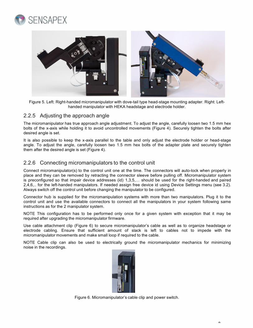
Figure 5. Left: Right-handed micromanipulator with dove-tail type head-stage mounting adapter. Right: Left- handed manipulator with HEKA headstage and electrode holder.
2.2.5 Adjusting the approach angle
The micromanipulator has true approach angle adjustment. To adjust the angle, carefully loosen two 1.5 mm hex bolts of the x-axis while holding it to avoid uncontrolled movements (Figure 4). Securely tighten the bolts after desired angle is set.
It is also possible to keep the x-axis parallel to the table and only adjust the electrode holder or head-stage angle. To adjust the angle, carefully loosen two 1.5 mm hex bolts of the adapter plate and securely tighten them after the desired angle is set (Figure 4).
2.2.6 Connecting micromanipulators to the control unit
Connect micromanipulator(s) to the control unit one at the time. The connectors will auto-lock when properly in place and they can be removed by retracting the connector sleeve before pulling off. Micromanipulator system is preconfigured so that impair device addresses (id) 1,3,5,… should be used for the right-handed and paired 2,4,6,.. for the left-handed manipulators. If needed assign free device id using Device Settings menu (see 3.2). Always switch off the control unit before changing the manipulator to be configured.
Connector hub is supplied for the micromanipulation systems with more than two manipulators. Plug it to the control unit and use the available connectors to connect all the manipulators in your system following same instructions as for the 2 manipulator system.
NOTE This configuration has to be performed only once for a given system with exception that it may be required after upgrading the micromanipulator firmware.
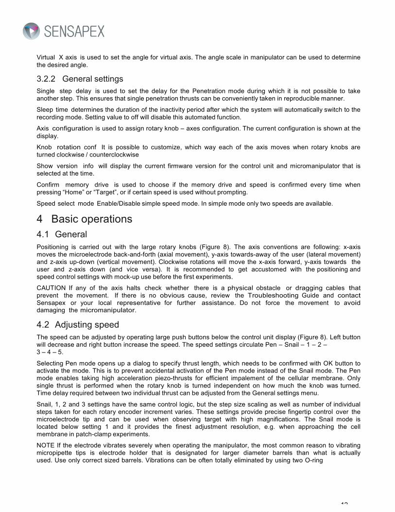
Use cable attachment clip (Figure 6) to secure micromanipulator’s cable as well as to organize headstage or electrode cabling. Ensure that sufficient amount of slack is left to cables not to impede with the micromanipulator movements and make small loop if required to the cable.
NOTE Cable clip can also be used to electrically ground the micromanipulator mechanics for minimizing noise in the recordings.
Figure 6. Micromanipulator’s cable clip and power switch.

9
CAUTION Note that it is very important not to load the manipulator with drag from stiff and heavy cables, as this may interfere with normal function. Unorganized cables are also one of the most common drift sources when touched or moved by the user during the experiments.
Micromanipulators have permanently attached white flat cables that connect x- and z-axis to the control electronics. The white cables cannot tolerate large stress. Take care not accidentally pull them during installation or use, and ensure that they are free to move during normal operation.
2.2.7 Starting the system for the first time
After all the manipulators have been individually configured, connect all of them to the control unit and power it on. Current firmware version of the control unit is displayed during the initialization. Micromanipulator firmware version can be displayed from the General Settings menu.
2.2.7.1 Zero position initialization
After initialization, dialog screen for initialization of the zero position is displayed (=absolute position). It can be performed for the currently selected device id, all devices or it can be skipped by back button. This functionality should be performed after the installation and every time if the micromanipulator has been accidentally moved by hand during or between operating it with the control unit.
CAUTION Always remove the microelectrode before initializing zero position, which will drive each of the axes to their extremes, to prevent collision and damage. Also make sure that each micromanipulator in the system has enough clearance to complete the initialization movements.
The initialization drive is performed by first retracting x-axis, then moving y-axis all the way to the front and lifting z-axis all the way up and. After this the axis are returned to the Home memory position. Same movement sequence is also used for memory position driving. Pressing reset button before switching off the control unit will save the current position to the micromanipulator and control unit memories. This will prevent initialization dialog to pop up unless the micromanipulator has been manually moved while powered off.
2.2.7.2 Speed calibration
After installing the load to the manipulator (headstage, electrode holder, etc.), speed calibration should be executed (Menu -> Device settings -> Speed calibration). This will calibrate the initial control voltage according to the weight load conditions.
CAUTION Always remove the microelectrode before Speed calibration, which will drive each of the axes close to their extremes, to prevent collision and damage. Also make sure that each micromanipulator in the system has enough clearance to complete calibration routines.
Your micromanipulator is now ready for use. We recommend getting accustomed with the positioning with mock-up use before the first use in the real experiments.
3 Control unit
3.1 Controls
The control unit provides ergonomic and intuitive interface for the precise positioning. The main display view shows the current position information in micrometers, speed setting, id of the micromanipulator that is operated and battery status (Figure 7). A chg symbol will interleave with the battery symbol when the charger is plugged and the battery is charging. The display also shows context specific function of the push-buttons located next to the display (Menu, Reset, Home and Target in the main display).

10
Reset id:2 Home
Y
Z
X
00010
Menu
04585
Spd: 4
-02340
Target
Figure 7. Main display
The control unit user interface is shown below in Figure 8.
Figure 8. Control unit from the top.
Large rotary knobs are connected to the optical encoders and enable controlling each of the axes individually. The knob – axis configuration can be customized from the menu and display shows the current assignments. In Figure 8 the knobs control the X, Y and Z-axis from left to right, respectively.
Speed- and Speed+ are the left and right large round buttons below the display, respectively, which control the positioning resolution and speed. The speed settings circulate from Pen – Snail – 1 – 2 – 3 – 4 – 5.
Micromanipulator selection is performed by keeping the Speed- or Speed+ buttons down for longer than one second. Micromanipulators are circulated backward and forward on the order of their device id numbers with Speed- and Speed+ buttons, respectively. Device settings, memory positions and speed-settings are micromanipulator specific and saved to the micromanipulators’ memory.
NOTE Odd ids (1,3,5,…) are reserved for right-handed and even (2,4,6,...) for the left-handed micromanipulators to ensure logical operation in the mirror imaged configurations.
Home & Target are used to save and retrieve memory positions. Keeping the button pressed down for longer than one second will save the current location. Message is show in the display to confirm the operation. Memory positions are retrieved by normal pressing of the button and confirming action by OK button.
Reset button will reset the position readings in the display. Pressing the Reset button will also save the absolute position information to the micromanipulator.
Recording mode can be activated by keeping the Reset button down for longer than one second. A key symbol appears on the left upper corner before the display and micromanipulator(s) are powered off (the micromanipulators do not require power to hold their current position. This also inactivates the rotary knobs to prevent accidental movements during the recording. The control unit and micromanipulators can be returned to the normal operating mode by pressing the Reset button. The key-lock can be released by pressing Reset button again for longer than one second.

11
NOTE The control unit also has power saving feature that will put the system to the recording mode after a certain time of inactivity that can be defined from the General Settings menu.
Menu button takes you to the main menu. The Menu structure is described in next chapter. Push-buttons next to the display are used to navigate and perform actions in the menus. Their function is indicated in the display area closest to the button. In general, buttons on the right side of the display are used to scroll down / up. Reset button is used to navigate back and Menu button to select / confirm (OK button).
3.2 Main menu
Device settings include micromanipulator specific functionalities and adjustments, which are saved to the micromanipulator (see 3.2.1).
General settings include functions that are used to customize the control unit user interface and micromanipulator operation features (see 3.2.2).
Init zero position will drive each axis to its extreme to re-establish absolute position information in case the micromanipulator has been manually moved.
Clear relative pos will return display mode to show absolute position information instead of the relative one if Reset button has been pressed.
Enable PC mode will set the controller for the PC mode. This mode is used when controlling the micromanipulator with the PC or when updating the micromanipulator firmware.
Enable Simul. step will enable the multimove mode to move all manipulators simultaneously.
Enable Virtual X will enable the virtual X operation (visible only if the angle of the virtual axis has been set in device settings).
3.2.1 Device settings
Device selection is used to select the micromanipulator that is operated at the time (similar to quick button operation).
Detect devices is used to scan micromanipulators that are currently connected to the control unit. This function is automatically run during the initialization after switching on the control unit. This function should always be run when new micromanipulator is added to the system while the control unit is on.
Change address is used to define micromanipulator id. Use pairless ids for right-handed and paired for left- handed micromanipulators. The micromanipulators are pre-configured in the factory for your system if such information has been available upon the order. Follow the instructions in section 2.2.6 if you need to change the configuration.
Mem drive speed default value for memory position drive: Slow, Mid or Fast.
Speed calibration is used to run calibration algorithms to adjust control parameters according to manipulator load. Speed calibration should be performed after attaching the measurement device (headstage, electrode holder, etc.) to the manipulator.
Speed near target setting can be used to activate gradual acceleration / deceleration feature near the target when using memory positions. This may be beneficial when retracting the electrode from the tissue to prevent tissue vibrations. Note that the positioning accuracy is the same in all settings.
Memory drive order configuration It is possible to customize, which order the axis are moved in the memory positioning operations. This configuration is available in the Device settings menu and can be adjusted for each manipulator. The default value moves x-axis first / last and vertical setting will move the z- axis first / last. Vertical setting also leaves the z-axis to the upmost position after initialization movements. Please note that the Memory drive order configuration normal/vertical setting is also used to set the normal/inverse virtual axis feature (see 4.9.1).
Simultaneous step is used to adjust the length of movement which each manipulator will move by single multimove command.
12
Virtual X axis is used to set the angle for virtual axis. The angle scale in manipulator can be used to determine the desired angle.
3.2.2 General settings
Single step delay is used to set the delay for the Penetration mode during which it is not possible to take another step. This ensures that single penetration thrusts can be conveniently taken in reproducible manner.
Sleep time determines the duration of the inactivity period after which the system will automatically switch to the recording mode. Setting value to off will disable this automated function.
Axis configuration is used to assign rotary knob – axes configuration. The current configuration is shown at the display.
Knob rotation conf It is possible to customize, which way each of the axis moves when rotary knobs are turned clockwise / counterclockwise
Show version info will display the current firmware version for the control unit and micromanipulator that is selected at the time.
Confirm memory drive is used to choose if the memory drive and speed is confirmed every time when pressing “Home” or “Target”, or if certain speed is used without prompting.
Speed select mode Enable/Disable simple speed mode. In simple mode only two speeds are available.
4 Basic operations
4.1 General
Positioning is carried out with the large rotary knobs (Figure 8). The axis conventions are following: x-axis moves the microelectrode back-and-forth (axial movement), y-axis towards-away of the user (lateral movement) and z-axis up-down (vertical movement). Clockwise rotations will move the x-axis forward, y-axis towards the user and z-axis down (and vice versa). It is recommended to get accustomed with the positioning and speed control settings with mock-up use before the first experiments.
CAUTION If any of the axis halts check whether there is a physical obstacle or dragging cables that prevent the movement. If there is no obvious cause, review the Troubleshooting Guide and contact Sensapex or your local representative for further assistance. Do not force the movement to avoid damaging the micromanipulator.
4.2 Adjusting speed
The speed can be adjusted by operating large push buttons below the control unit display (Figure 8). Left button will decrease and right button increase the speed. The speed settings circulate Pen – Snail – 1 – 2 – 3 – 4 – 5.
Selecting Pen mode opens up a dialog to specify thrust length, which needs to be confirmed with OK button to activate the mode. This is to prevent accidental activation of the Pen mode instead of the Snail mode. The Pen mode enables taking high acceleration piezo-thrusts for efficient impalement of the cellular membrane. Only single thrust is performed when the rotary knob is turned independent on how much the knob was turned. Time delay required between two individual thrust can be adjusted from the General settings menu.
Snail, 1, 2 and 3 settings have the same control logic, but the step size scaling as well as number of individual steps taken for each rotary encoder increment varies. These settings provide precise fingertip control over the microelectrode tip and can be used when observing target with high magnifications. The Snail mode is located below setting 1 and it provides the finest adjustment resolution, e.g. when approaching the cell membrane in patch-clamp experiments.
NOTE If the electrode vibrates severely when operating the manipulator, the most common reason to vibrating micropipette tips is electrode holder that is designated for larger diameter barrels than what is actually used. Use only correct sized barrels. Vibrations can be often totally eliminated by using two O-ring

13
electrode holders that provide stable clamping of the pipette. They also improve overall stability of the recording especially if pressure is applied to the micropipette.
Speed settings 4 and 5 are designated for rapid positioning to bring the microelectrode tip in proximity of the target. Smaller speed settings should be used for precision positioning. The control logic is different from the other speed settings. Continuous stepping is used when the rotary encoders are turned faster than certain pre-defined rotation speed. In addition to providing faster speed this also eliminates sound and vibrations.
4.2.1 Simple speed mode
Simple speed mode can be enabled and configured Menu à General Settings à Speed select mode. In simple mode only two speeds, slow and fast, are available with speed up/down buttons. User can freely configure which two speeds are available. This feature is useful if you always use certain speed for approaching the target (e.g. 5) and certain speed to do the actual recording (e.g. 2) as you don’t need to push speed up/down several times to change the speed between fast and slow.
4.3 Memory positions
Two memory positions, Home and Target, are available through quick buttons. Saving the current location is done by keeping the button pressed down for longer than one second. Retrieving the saved memory position through automated positioning of all three axes is done by normal pressing of the button. This will open a dialog display that show target coordinates, driving speed (Slow, Mid, Fast) and requires confirmation by OK button to launch the function (or not performing it by pressing back button). The default value for driving speed can be changed from Mem drive speed in Device settings. The dialog display is implemented to prevent unintended memory positioning. Each micromanipulator has two memory positions, which are saved to their memory.
NOTE The speed calibration (see 2.2.7.2.) sets also the control voltage values for the automated driving to memory position. The result of speed calibration is different depending on which default value for Mem drive speed is chosen in Device settings. For most optimal performance set the default value for Mem drive speed to the value which you will be mostly using before running the speed calibration.
NOTE The dialog display when pressing “Home” or “Target” can be disabled in Menu à General Settings à Confirm Memory Drive.
4.4 Resetting display
Displayed position can be reset by using Reset button. This enables keeping track of the current position relative to a set location (e.g. brain surface in in vivo experiments). Clear relative pos. command in the main menu can be used to return absolute position readings to the display.
4.5 Electrode exchange
The micromanipulation system provides convenient microelectrode exchange through combination of programmed memory positions and quick retrieval mechanisms that are integrated to manipulators.
When starting the experiments, save you preferred home position using memory operations. The memory positions are stored to the micromanipulator’s memory and remain the same even when the control unit is powered off until changed by the user. When approaching the target, save the location close to the specimen to Target memory position. The tip should be within the field of view of the microscope with low magnification setting. Note that microelectrode lengths may vary considerably and, therefore, it is necessary to leave enough clearance to the target to avoid accidental collision. For the microelectrode exchange, return to the home position and use the micromanipulator’s quick retrieval mechanism for convenient access to the electrode (Figure 9). Change the electrode, use quick mechanism to return to the normal operating position and return to the target location using Target memory button.
NOTE X-axis is withdrawn in memory operations first to provide maximum clearance from the objective before moving the other axis. The default order can be changed from Device Settings, Med Drive Order.

14
A B
C D
Figure 9. Electrode-exchange mechanisms: (a) Back-flip (b) back-flip with back-slide (c) side-rotate and (d) side-rotate with back-slide.
CAUTION Quick mechanisms for the microelectrode retrieval require large clearance that is specific for each option. E.g. back-flipping action will make the electrode to retract in an arc (Figure 9a). Radius of this arc depends on the length from the pivoting point to the electrode tip that is specific for each installation. Ensure that your system provides required clearance for microelectrode to retract without colliding to e.g. objective or other instruments used in the experiments.
4.6 Power-Off Recording Mode
When the microelectrode has been positioned to the target and the desired recording configuration has been established (e.g. a whole-cell configuration in patch-clamp) the Power-Off Recording Mode should be activated by pressing Reset button for longer than one second. This will lock the rotary knobs to prevent accidental movements and power off the micromanipulators for zero noise emission. It also puts control unit to stand-by mode to save battery. Returning to the normal operating mode is done by pressing the Reset button to wake up controller and pressing the Reset button again for longer than one second to unlock keys. This prevents accidental waking up and positioning during recordings.
NOTE The micromanipulators also have hardware switch to power off the micromanipulators for service purposes (Figure 6). However, operating it during experiments is not necessary because the Recording mode will already power off the micromanipulator and doing that would give rise to movement artifacts that might cause losing of the recording.
4.7 Initialize absolute position information
The micromanipulators have integrated linear position sensor at each of their axis that provide absolute position information. However, the absolute position information is lost if any of the axes is accidentally moved by hand during the operations or while micromanipulation system is powered-off. Init zero position command can be used to re-establish absolute position information.

15
The position information stored to the micromanipulator is compared to that in the control unit memory each time that the system is powered on. If these values differ, a dialog display pops up during start up that requests whether to execute Init zero position function for the micromanipulators with differing values. Pressing OK will launch the function and back enables continuing use without the initialization.
NOTE The current position is saved to the micromanipulator’s memory only when pressing Reset button or when activating Recording mode. Therefore, the values stored in the micromanipulator will differ even when it has been normally operated since the last storing and before switching off the control unit. Use Reset button before switching off the control unit to prevent dialog popping up.
NOTE It is always possible to press Back button on the dialog screen and continue normal operation without Initializing zero positions. If the micromanipulator has been manually moved the absolute readings will differ from the real values, but this does not otherwise affect normal use.
CAUTION Init zero position will drive each of the axes to their extreme. Therefore, this function should only be performed in the absence of the microelectrode, pipette or tool to prevent collisions. Always ensure that the micromanipulator has enough clearance to perform this function before starting it.
4.8 Charging battery
The control unit is delivered with battery charged. Please observe the battery indicator in the information display for remaining battery life and recharge when necessary. The battery can be charged at any time and it is not necessary to let it fully empty before charging.
To use the charger (Figure 2), plug the power cord to the charger and the charger plug to the corresponding connector at the control unit. The control unit display will show chg-symbol. The charger can be left plugged without risk of over-charging. It is possible to continue using the micromanipulator while charging the battery. This is not recommended for the sensitive electrophysiological measurements because this may cause some 50/60 Hz noise.
CAUTION The charger should be connected to earthed mains outlet only.
4.9 Virtual X axis
The virtual X axis function is used to control the movement of micromanipulator in orthogonal axes, since the normal X-axis is tilted (see Figure 10). The virtual X axis is orthogonal to real Y and Z axes. To use the virtual X axis, first adjust the real X axis to the desired angle (see 4.2 for instructions). Read the angle of real X axis from the angle scale in the manipulator. Go to the control unit Menu à Device settings à Virtual X axis. Change the X rotation angle value in control unit to the same value which is indicated by the angle scale in the manipulator using the two buttons in right side of the control unit display. Press OK to set the value to the controller. Go back one level in the menu (or press back button until you are in the initial screen and then press menu once) to go to the Menu à Enable Virtual X. Press OK to enable the virtual axis. Pressing OK again will disable the virtual axis. Press back to return to the main screen. The naming of the axes has changed from Y-Z-X to Y-H-D to indicate that the virtual axis operation is enabled.
Please note that in virtual axis operation the speed setting 5 is not available due the different control method of axes movement. The virtual axis is designed to work with 0-50 degrees angle values for X axis.
NOTE Press Menu button in main screen for 2 seconds to quickly Enable/Disable Virtual X

16
Z
Z
Y Virtual X
Y X
X Virtual X
Figure 10. Virtual axis (4th axis) in the micromanipulator
4.9.1 Inverse virtual axis
If the approach angle of X-axis is adjusted to 0-degrees, it is possible to enable inverse virtual axis for approach axis, i.e. the virtual X and real X are switched in Figure 10. To enable this feature, change Memory drive order in Device Settings to Vertical before enabling the Virtual X. The angle value in Virtual X in Device settings is now the angle between Z- and virtual axis, i.e. 0 degrees would mean approach in Z-direction. The maximum allowed angle value is 45 degrees.
4.10Multimove
Multimove feature has been implemented that enables commanding multiple manipulators to move z-axis up / down in set increments. Length of the movement can be configured in the Device settings menu and the feature can be enabled / disabled in the General settings menu.
The multimove functionality is available at the Snail mode, where the memory position buttons are used to move multiple manipulators up / down. For longer movements, the manipulators are moved step wise in 10 µm and next increment is taken only after each manipulator has finished its movement. This way the simultaneous movements cannot be more than ca. 10 µm out of synchrony during simultaneous movements.
5 Options and accessories
The micromanipulators can be customized for plug-and-play installation using selection of standard options and accessories. C accessories, such as special stands and tool holders, are also available on request (not included in the list price).
5.1 Mounting options
Standard options include magnet or bolt mounting. Please see section 2.2.2 for more information. Please contact Prior Scientific if your application would require other type of mounting option.

17
5.2 Quick mechanisms for microelectrode exchange
Standard options include selection of four possible quick mechanisms for the microelectrode exchange: back-flip, back-flip + back-slide, side-rotate and side-rotate + back-slide (Figure 9).
5.3 Approach angle options
Micromanipulators are delivered with either a normal 0-50 degrees or steep 40-90 degrees approach angle range that can be specified upon ordering. Please contact Sensapex if you would like to change the option of your current micromanipulator.
5.4 Weight load
The manipulator has 0-70 g or 70-120 g weight load capacity according to the specification in order. The 70- 120 g load capacity can be changed later to 0-70 g. The instructions are available for registered users in Sensapex support web pages.
NOTE The 70-120 g weigh load capacity is compatible only with 0-30 degrees X-axis approach angle.
5.5 Adapters
Either a microelectrode holder or head-stage adapter is included in the delivery for each micromanipulator (Figure 2). Additional adapters can be purchased from Sensapex. Please contact us if you required customized adapters in your application.
5.6 Connector hub
4-to-1 connector hubs are supplied with a system that has more than two micromanipulators. They can be also purchased at any time when expanding single or dual micromanipulation system in to multiple manipulator system. The connector hubs can be daisy chained to provide required number of connectors.
6 Maintenance and service
The micromanipulator has been designed to be a reliable instrument. In case of troubles, please review the troubleshooting guide and contact Sensapex or your local representative if issue has not been resolved. The user operations not specifically mentioned in this section are prohibited and may void the warranty.
CAUTION This instrument contains no user serviceable parts or components. Contact Prior Scientific for arranging service. Disassembling the product or attempting self-repair is prohibited and will void the warranty.
6.1 Troubleshooting guide
6.1.1 More than one micromanipulators are connected and none or only some of them work normally
Diagnose: First, try restarting the system to eliminate software halt possibility. Disconnect all but one micromanipulator and test if it works normally. Test the same with another individual. Note what device id each micromanipulator has. If micromanipulators work normally when connected individually and more than one has the same device id, conflicting device id is the cause of the problem.
Fix: Configure device ids according to the section 2.2.5

18
6.1.2 One or more of the micromanipulator axis do not move at all or move very slowly
Diagnose: First, try restarting the system to eliminate software halt possibility. This problem may in general result from excessive loading condition. Verify that the micromanipulator load due to attached head-stage and/or tools does not exceed the specified range of your product. Also ensure that cable drag is not causing large loading.
Fix: Reduce weight to allowed range or contact Sensapex for modification to handle larger loading. Organize cables to prevent dragging. If no obvious cause is visible and restarting does not help, please contact Prior Scientific for further assistance.
6.1.3 One or more of the micromanipulator axis halts after normal operation
Diagnose: First, try restarting the system to eliminate software halt possibility. Verify that there is no physical obstacle or cable catch/drag that prevents movement. If no physical obstacles or cable drag is observed and restarting does not help, halting may be due to dust or particles that have got into the piezo-drive or linear bearings (e.g. crystallization of accidental saline spill). The two alternatives can be diagnosed by switching off the control unit and gently trying to move the micromanipulator axis by hand. This should not take much force (holding force is ~6 N). Do not enforce the movement with large force! If there is clearly defined, short and repeatable position in the movement range with increased resistance and possible clicking sound, there is particle in the bearings. If the friction force upon manual movement is varying over the range in less specific way or there a grinding feeling to it, the issue is located within the piezo-drive.
Fix: Remove possible obstacle and organize cables to eliminate catch/drag. If the issue is within bearings, contact Sensapex or your local representative for arranging service. If the issue is within piezo-drive, try moving the affected axis back-and-forth over the whole range 5 times. Switch on the control unit and try normal operation. Assist the positioning first by hand if needed and see if normal operation is recovered after positioning few times end-to-end. If this does not work, contact Prior Scientific to arrange service.
6.1.4 Erratic movements
Diagnose: First, try restarting the system to eliminate software halt possibility. The most likely reasons are loosely connected mechanical parts or cable drag. Check all mounting and angle adjustment screws. Also check that the electrode or head-stage holder is firmly fixed in the adapter plate, and that the electrode is properly tightened to its holder. Check that cables are properly organized and have enough slack not to cause directional pull during positioning.
Fix: Securely tighten all the bolts and ensure firm mechanical connections. Change to proper electrode holder if one used does not clamp the micropipette firmly. Organize cables if required. If no obvious cause is observed and restarting system does not help, please contact Prior Scientific for further assistance.
6.1.5 Drift
Diagnose: The positioning mechanism of piezo-drives is inherently drift-free if loaded according to the specifications. The most likely causes of the drift are loose mechanical connections, unstable electrode holder and cable drag. Verify that these are not an issue following instructions in 6.1.2 and 6.1.4.
Fix: Possible issues with loose mechanical connections, electrode holder or cable drag should be fixed following instructions in 6.1.2 and 6.1.4. Two O-ring electrode holders are recommended for smaller drift, especially for patch-clamping experiments and if pressure injections are used. Thermal drifts are unavoidable physical phenomenon that affects all the mechanics in your setup. These can be minimized by temperature control and by eliminating transient heat sources as well as air drafts. Note that thermal drifts are directly proportional to the total length of the electrode holder and/or head-stage. The closer the manipulator is mounted to the target and the shorter the distance from the mounting point to the electrode tip, the smaller the thermal drifts are in magnitude (also improves overall mechanical stability).

19
6.1.6 Change in behavior over time
Diagnose: Changes in the positioning behavior, especially under large loading, may be observed over longer time period, which is not explained by issues mentioned in 6.1.1-6.1.5.
Fix: Piezo-drives are designed for very large number or positioning cycles that should not be achieved during its life-time. However, long term use in different operating conditions with exposure to dust, particles and other possible interferences may affect the performance over time. Try performing manual movements to recover normal function as instructed in 6.1.3. If this does not work, contact Prior Scientific to arrange service.
6.1.7 Manipulators are not detected
Diagnose: When the control unit is powered on, it detects automatically the connected micromanipulators. If no manipulators are found, control unit indicates Device ID: 0.
Fix: Make sure that all micromanipulators are connected properly to control unit and then re-start the control unit. If this does not work, run the device detection manually. Use the Device settings first to detect the manipulators (Menu à Device settings à Detect devices) and then to select the manipulators (Menu à Device settings à Device selection).
6.2 Firmware updating
Please let us know if you observe malfunctioning (=bug) or if you would like us to implement new features to further improve the product. The micromanipulator is controlled by modern embedded electronics, which enables changing the operation and tuning the functionalities with firmware updates.
Visit product support section at www.sensapex.com to see if there are new firmware updates available for your product.
CAUTION When downloading firmware files, please note that some internet browsers change file extensions automatically when downloading files - make sure that you save the firmware files with the .hex extension to your computer.
6.2.1 Step-by-step instructions for updating the control unit firmware
1. Install firmware updating software by running the executable file (available at product support section at www.sensapex.com) and following installation wizard instructions.
2. Connect USB cable to the computer and let Windows install the suitable driver for it. If this does not work automatically, download suitable driver for your operating system from http://www.ftdichip.com/Drivers/VCP.htm and install the USB cable manually using that driver. The USB cable should be listed as USB-RS485 cable hardware in your computer and it should available as a serial port (COM).
3. Verify that the control unit is powered off and disconnect all the micromanipulators from it. 4. Connect USB cable to the control unit and start Firmware Upgrade Tool 5. Open Settings from Program menu (Figure 11).

20
Figure 11. Program menu
6. Configure the COM Port to match the USB cable’s COM address (Figure 12; COM6 in the example). Other settings should be left to their default values as shown in Figure 12. Press OK and return to the main program
Figure 12. Settings menu.
7. Press button with pause symbol and power on the control unit. The control unit display will remain dark during update process.
8. Wait for 10 s and press button with stop symbol. When successfull, the program will show information on the boot-loader version and hardware (Figure 13).
Figure 12. Successful connection with the control unit
9. Press open folder symbol and open the new firmware file (CU*.hex file type). 10. Press button with downwards red arrow symbol in the main program to update firmware. Verify that
”Write Complete” is displayed to confirm successful updating (Figure 14).

21
Figure 14. Successfull update process
11. Power off the control unit and reconnect micromanipulators. The update process is now successfully completed and new firmware is used upon next powering on of the system.
6.2.2 Step-by-step instructions for updating the micromanipulator firmware
NOTE Each micromanipulator needs to be updated individually one at the time. 1. Verify that the control unit is powered off and disconnect all the micromanipulators from it. 2. Connect USB cable to the control unit and power it on. 3. Set control unit to PC mode by using Enable PC mode setting in the main menu 4. Start Firmware Upgrade Tool and configure its settings if required as instructed in 6.2.1. 5. Press button with pause symbol and connect micromanipulator’s cable to the control unit. 6. Wait for 10 s and press button with stop symbol. When successfull, the program will show
information on the boot-loader version and hardware (Figure 13). 7. Press open folder symbol and open the new firmware file (MCU*.hex file type). 8. Press button with downwards red arrow symbol in the main program to update firmware. Verify that
”Write Complete” is displayed to confirm successful updating (Figure 13). 9. Restart the control unit. Verify that micromanipualtor’s Device settings are according to your
preferences and verify that device ids do not conflict with each other’s in multiple manipulator systems (see 2.2.5). The update process is now successfully completed.
6.2.3 Device detection after firmware upgrade
After updating the firmware for the control unit and/or micromanipulator, the manipulator may not be automatically recognized by the control unit (= display shows Id0). If such happens, use the Device settings menu first to detect the manipulator (Menu à Device settings à Detect devices) and then to select the manipulator (Menu à Device settings à Device selection). The automatic detection should work normally after this.

22
7 Specifications
The system is indented to be used in laboratory environment in room temperature (Pollution Degree II) that is free from mechanical vibrations, electrical noise and transients. Specifications are presented for such environment.
SMX micromanipulator Positioning range: 20x20x20 mm3 (x-y-z) Min. step size: 7 nm Closed-loop control: 3 µm repeatability Max. speed: ~5 mm/s Load: 0-70 g | 70-120 g* Electrode drive angle: 0 – 50 | 40-90 degrees* Table mounting: magnet | bolt (switchable by user) Electrode retrieval: back-flip | back-slide** | side-rotate Dimensions (WxHxL): 39x93x77 mm Weight: 295-375 g Electrical input: 12 VDC, max. 1.5 A * 70-120 g option is compatible with 0-30 degrees approach angle ** Back-slide is always combined with back-flip or side-rotate
SMX control unit Rotary optical encoders and backlit display Six speed settings and penetration mode 4th virtual axis for orthogonal positioning in angled approach Two programmable memory positions for each micromanipulator Single control unit can operate up to 14 micromanipulators* USB computer interface** Charger input: 100-240 VAC, 50-60 Hz; max. 0.7 Arms (grounded 3-prong mains outlet required) Batteries: Li-ion (rechargeable) Dimensions: 190x210x40 mm Weight: 510 g *1-to-4 connector hubs are provided for multiple manipulator systems **Software development kit available
The battery has built-in protection
8 Warranty
Product is warranted against defects in material and workmanship limited to repair and replacement of defective product or its components for one (1) year after the date of shipment, provided that the product has been operated in accordance with the instructions in this manual. The warranty is extended to two (2) years with the same terms and free of charge if the product is registered to us within 30 days of the delivery. Please go to www.sensapex.com/support/ for product registration. Product needs to be transported for the service in its original shipping packaging. The cost of shipment is paid in both ways by Sensapex for the authorized service returns. If the return is unauthorized the costs are paid both ways by the user.
Warranty will not apply if the product has been damaged by accident, abuse, misuse or unauthorized repairs or modification by user. The liability of Sensapex Oy arising out of supplying of the product, or its use, whether under the foregoing warranty, a claim of negligence, or otherwise, shall not in any case exceed the cost of correcting defects in the product. All liability shall terminate upon expiration of the specified warranty period. The foregoing shall constitute the sole remedy of the buyer. In no event shall Sensapex Oy be liable for consequential or special damages.

23
9 Manufacturers declaration of conformity
Manufacturer’s Name: Sensapex Oy
Manufacturer’s Address: Teknologiantie 13, 90590 Oulu, Finland declares this product:
Product Name: SMX-series micromanipulation system conforms to the following standards:
Low voltage directive 2006/95/EC: EN 61010-1:2010 EMC directive 2004/108/EC: EN 61326:2006; EN 55011:2009/CISPR 11:2009 (Class B, Group 1) Best of our knowledge RoHS compliant (2006/95/EC) WEEE directive 2002/96/EC Batteries and Accumulators Directive 2006/66/EC
Supplementary Information: “The product complies with the requirements of the Low Voltage Directive 2006/95/EC and the EMC Directive 2004/108/EC”
Date: 27.2.2013
Mikko Vähäsöyrinki, CEO Sensapex Oy