microminiature linear split stirling cryogenic cooler for...
TRANSCRIPT
Microminiature Linear Split Stirling
Cryogenic Cooler for Portable
Infrared Applications
A. Veprik, H. Vilenchik, S. Riabzev, and N. Pundak
Ricor Lrd, Cryogenic and Vacuum Systems,
En Harod Ihud, 18960, Israel
ABSTRACT
Novel tactics, employed in carrying out military and antiterrorist operations, call for the devel-
opment of a new generation of warfare, in addition, sophisticated portable infrared (IR) imagers for
surveillance, reconnaissance, targeting and navigation play an important role. The superior perfor-
mance of these imagers relies on novel optronic technologies and cooling the IR focal plane arrays
(FPA) to cryogenic temperatures.
Traditionally, closed cycle rotary driven Stirling cryogenic engines are used for this purpose.
As compared to their off-the-shelf available linear rivals, they are lighter, more compact and nor-
mally consume less electrical power.
Recent technological advances in industrial development of high-temperature (100K) IR de-
tectors initialized attempts for developing microminiature cryogenic coolers, both of rotary and
linear types. Linearly driven cryogenic coolers appear to be more suitable for these applications.
The advantages include flexibility in the system design, longer lifetime, low exported vibration
and aural stealth. Recent progress in designing high efficiency “moving magnet” resonant linear
drives and accompanied electronics enable further reduction in the cooler size, weight and power
consumption.
The development and project status of the Ricor model K527 microminiature split Stirling
linear cryogenic cooler designed especially for portable infrared imagers is reported herein.
INTRODUCTION
Effective carrying out of military and antiterrorist operations requires development and de-
ployment of new sensors. In particular, sophisticated portable infrared (IR) imagers, converting the
thermal battlefield into a dynamic visual imagery, enhance the observation and command control
capabilities of the leaders of combat infantry and Special Forces. The superior performance of such
imagers is achieved by using novel optronic technologies along with cooling the infrared focal
plane arrays (FPA) to cryogenic temperatures using closed cycle Stirling cryogenic engines. In
spite of the recent wide spread use of uncooled infrared detectors, it is still widely accepted that the
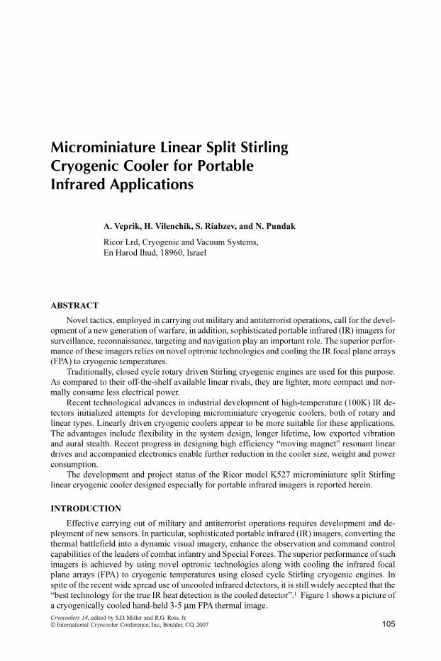
“best technology for the true IR heat detection is the cooled detector”.1 Figure 1 shows a picture of
a cryogenically cooled hand-held 3-5 m FPA thermal image.
105Cryocoolers 14, edited by S.D. Miller and R.G. Ross, Jr.©¶International Cryocooler Conference, Inc., Boulder, CO, 2007
Over the past few years industrial advances have permitted the development of a new InAlSb
diode technology based upon Antimonide Based Compound Semiconductors (ABCS). The detec-
tor offers lower dark currents at operating temperatures in the 100 K region.2 The cryocooler needed
for this application has a heat lift of approximately 180 mW at 100 K with an ambient rejection
temperature, consumes less then 5 W of electrical power, and weights less then 300 g.
Traditionally, integral rotary coolers are used for cooling the FPA of the portable IR imagers at
the optimal cryogenic temperature. As compared to their off-the-shelf linear rivals, they are lighter,
more compact and consume less electrical power. However, their inherent drawbacks, such as high
wideband vibration export, noise radiation and limited lifetime call for the development of novel,
long-life, acoustically and dynamically quiet micro miniature linear Stirling cryogenic coolers,
which compare to integral rotary coolers, in terms of weight and power consumption.
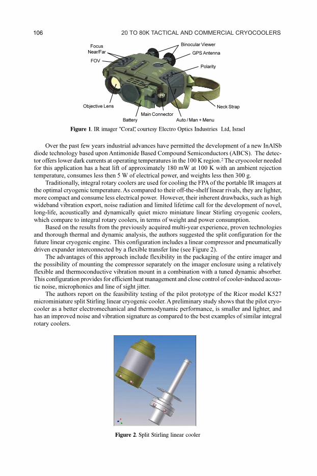
Based on the results from the previously acquired multi-year experience, proven technologies
and thorough thermal and dynamic analysis, the authors suggested the split configuration for the
future linear cryogenic engine. This configuration includes a linear compressor and pneumatically
driven expander interconnected by a flexible transfer line (see Figure 2).
The advantages of this approach include flexibility in the packaging of the entire imager and
the possibility of mounting the compressor separately on the imager enclosure using a relatively
flexible and thermoconductive vibration mount in a combination with a tuned dynamic absorber.
This configuration provides for efficient heat management and close control of cooler-induced acous-
tic noise, microphonics and line of sight jitter.
The authors report on the feasibility testing of the pilot prototype of the Ricor model K527
microminiature split Stirling linear cryogenic cooler. A preliminary study shows that the pilot cryo-
cooler as a better electromechanical and thermodynamic performance, is smaller and lighter, and
has an improved noise and vibration signature as compared to the best examples of similar integral
rotary coolers.
Figure 1. IR imager "Coral", courtesy Electro Optics Industries Ltd, Israel
Figure 2. Split Stirling linear cooler
20 TO 80K TACTICAL AND COMMERCIAL CRYOCOOLERS 106
Objective Lens
FOV
Neck Strap
GPS Antenna
Focus
Near/Far
Battery Auto / Man + Menu
Main Connector
Polarity
Binocular Viewer
LINEAR COMPRESSOR
The single piston linear compressor is driven by a “moving magnet” resonant electrodynamic
actuator. This allows obtaining a very high efficiency (in excess of 90%).3 The driving coil is sepa-
rated from the working fluid, thus preventing the cooler interior from contamination by the wire
insulation, and eliminating the leakage through the feed throughs.
The schematics of this compressor is shown in Fig. 3. The radially magnetized ring is placed
between the internal and external yokes made of the magnetically soft iron and shaped to accom-
modate the radial coil carrying AC current and to provide for the uniform distribution of the mag-
netic flux within the working air gap without oversaturating the yoke.3
In a motor of this kind, the interaction of the permanent magnetic field produced by the radially
magnetized ring with an alternating electromagnetic field yields the axial force which is applied
directly to the movable ring. The ring is rigidly attached to the compression piston which is ar-
ranged to slide freely inside the tightly matched cylinder sleeve. This causes the desired movement
of the compressor piston. For the sake of compactness, the support spring is located inside the
piston and provides for the resonant operation and centers the piston-magnet assembly.
It is important to notice that the environmental extremes (vibration, temperature) typical for a
portable hand-held imagers are less severe as compared to an airborne or vehicular application. For
the sake of compactness, price, ease of assembling and maintenance, the so-called “contact less”
approach which relied on flexural bearing was rejected. In Fig. 3a, both the piston and cylinder
sleeves are made of hardened and polished steel with no exotic surface treatment. This decision is
based on the technology currently used in the Ricor model K535 cryogenic cooler. In the course of
the accelerated life test 3 units have accumulated the equivalent of approximately 225,000 hours.
Theoretical Analysis
Theoretical analysis is required for the choice of the supporting spring stiffness and the optimal
design of the motor. Figure 3b shows the simplified model of the linearly driven compressor. The
piston-magnet assembly of total mass m0
is driven by the electrodynamic force f(t) = i, where is
the motor force/current constant and i is the motor current. The fluid mechanic interaction of the
piston and the cylinder head, in a simplistic approach, is represented as a parallel spring-dashpot
combination k0
, c0
.
The equations of motion4,5,6,7
, in the linear approximation, describe the dynamics of the linear
motor.
(1)
where L and R denote inductance and active resistance of the motor and u denotes the driving
voltage. The Fourier transforms
(2)
where is the driving frequency and j = ‰-1 , yields equations of motion in the frequency domain,
Figure 3. Schematic and Model of Linear Compressor
(a) Schematics of the linear compressor (b) Model of the linear compressor
MICROMINIATURE LINEAR SPLIT STIRLING CRYOCOOLER 107
the complex solutions for which are
(3)
From Eq. (3), the magnitudes of the above complex current and displacement are
(4)
where U0
is the voltage magnitude
From Eq. (4), the magnitudes of the voltage and current, which are needed to produce the
required stroke X0
, are
.
(5)
Further, the electrical power consumed by the motor8 is
(6)
Substitution of Eq. (4) and Eq. (5) into Eq. (6) and considering that U(jw)2 =ïU(jw)ï
2 yields
(7)
It may be shown from Eq. (7) that minimum power consumption
(8)
takes place at resonance when
(9)
Eq. (9) may be satisfied by varying the stiffness of the support spring or the moving mass with
the purpose of approaching the resonant frequency of compressor to the optimally chosen driving
frequency .
It is quite obvious that useful mechanical “PV” power produced by such a motor at resonance
is
(10)
From Eq. (8) and Eq. (10) follows the simple definition of COP for a resonantly driven com-
pressor
(11)
From Eq. (11), for the best performance, the quality factor = R/2 needs to be minimized.
For the idealized motor having uniform distribution of the magnetic flux in the air gap, this require-
ment is equivalent to the obvious requirements of the full use of the “coil volume”, using the wire
with minimal electrical resistance and maximizing the above magnetic flux. However, in the real
motor, the yoke's iron may be locally oversaturated; the magnetic flux may be distributed unevenly
in the air gap because of their finite length, complex geometry and boundary conditions. These
factors impose particular restrictions. When comparing different variants of the motor obtained as a
result of FEA-based modeling, the preference will be given to the motor having the smallest value
of the quality factor = R/2.
20 TO 80K TACTICAL AND COMMERCIAL CRYOCOOLERS108
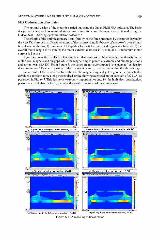
FEA Optimization of Actuator
The optimal design of the motor is carried out using the Quick Field FEA software. The basic
design variables, such as required stroke, maximum force and frequency are obtained using the
Gideon SAGE Stirling cycle simulation software.9
The criteria of the optimization are 1) uniformity of the force produced by the motor driven by
the ±1A DC current in different locations of the magnet ring, 2) absence of the yoke’s over satura-
tion at any conditions, 3) minimum of the quality factor . Further, the design restrictions are 1) the
overall motor length is 40 mm, 2) the motor external diameter is 32 mm, and 3) maximum motor
current is 1 A rms.
Figure 4 shows the results of FEA simulated distributions of the magnetic flux density in the
motor iron, magnets and air-gaps while the magnet ring is placed at extreme and middle positions
and current was ±1A DC. From Figure 5, the yokes are not oversaturated (the magnet flux density
does not exceed 2T) at any position of the magnet ring and at any current within the above range.
As a result of the iterative optimization of the magnet ring and yokes geometry, the actuator
develops a uniform force along the required stroke showing averaged motor constant of 22 N/A, as
portrayed in Figure 5. This feature is extremely important not only for the high electromechanical
performance but also for the dynamic and acoustic quietness of the compressor.
Figure 4. FEA modeling of linear motor
MICROMINIATURE LINEAR SPLIT STIRLING CRYOCOOLER 109
It is important to notice that at this stage we can make an assessment of the compressor COP.
For this purpose, the theoretical value of the equivalent damping co
= 12 kg/s obtained from the
Stirling cycle simulation is used, and obtained from the above FEA. Using Eq. (3), a COPres
of 95%
is found.
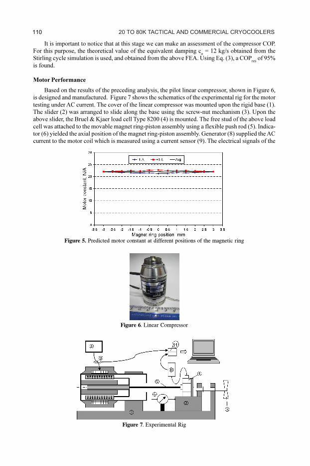
Motor Performance
Based on the results of the preceding analysis, the pilot linear compressor, shown in Figure 6,
is designed and manufactured. Figure 7 shows the schematics of the experimental rig for the motor
testing under AC current. The cover of the linear compressor was mounted upon the rigid base (1).
The slider (2) was arranged to slide along the base using the screw-nut mechanism (3). Upon the
above slider, the Bruel & Kjaer load cell Type 8200 (4) is mounted. The free stud of the above load
cell was attached to the movable magnet ring-piston assembly using a flexible push rod (5). Indica-
tor (6) yielded the axial position of the magnet ring-piston assembly. Generator (8) supplied the AC
current to the motor coil which is measured using a current sensor (9). The electrical signals of the
Figure 7. Experimental Rig
Figure 5. Predicted motor constant at different positions of the magnetic ring
Figure 6. Linear Compressor
20 TO 80K TACTICAL AND COMMERCIAL CRYOCOOLERS 110
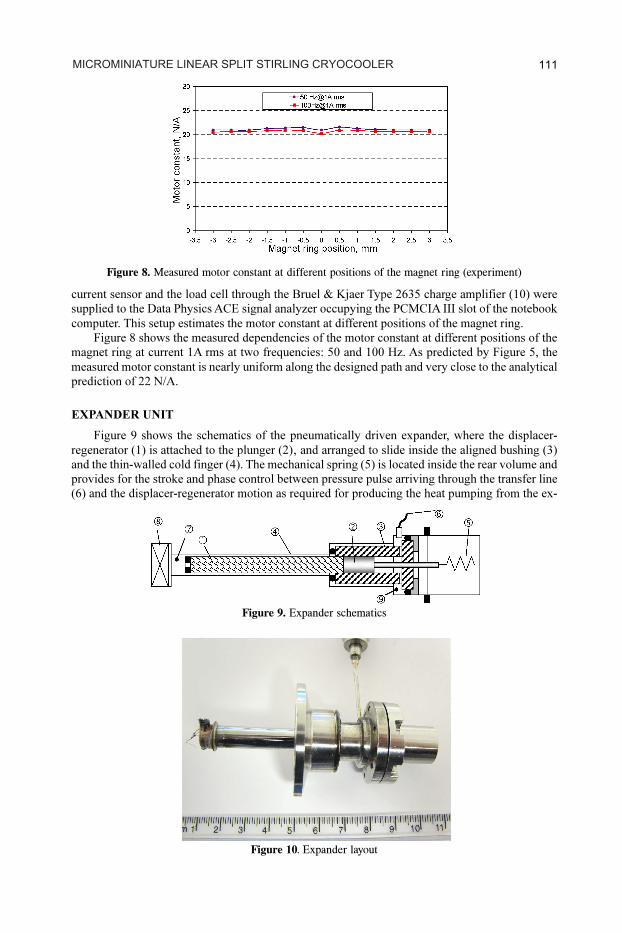
current sensor and the load cell through the Bruel & Kjaer Type 2635 charge amplifier (10) were
supplied to the Data Physics ACE signal analyzer occupying the PCMCIA III slot of the notebook
computer. This setup estimates the motor constant at different positions of the magnet ring.
Figure 8 shows the measured dependencies of the motor constant at different positions of the
magnet ring at current 1A rms at two frequencies: 50 and 100 Hz. As predicted by Figure 5, the
measured motor constant is nearly uniform along the designed path and very close to the analytical
prediction of 22 N/A.
EXPANDER UNIT
Figure 9 shows the schematics of the pneumatically driven expander, where the displacer-
regenerator (1) is attached to the plunger (2)‚ and arranged to slide inside the aligned bushing (3)
and the thin-walled cold finger (4). The mechanical spring (5) is located inside the rear volume and
provides for the stroke and phase control between pressure pulse arriving through the transfer line
(6) and the displacer-regenerator motion as required for producing the heat pumping from the ex-
Figure 8. Measured motor constant at different positions of the magnet ring (experiment)
Figure 9. Expander schematics
Figure 10. Expander layout
MICROMINIATURE LINEAR SPLIT STIRLING CRYOCOOLER 111
pansion space (7) to which the heat source (8) is thermally attached and the hot space (9), from
which the heat is further dissipated to the environment. The regenerator is shaped as a stack of
stainless steel mesh disks of the optimized geometry and porosity. Figure 10 shows the external
layout of the expander unit.
COOLER OPTIMIZATION
The preliminary cooler optimization relies on a Stirling cryocooler model using the Sage9 soft-
ware. Fine tuning is performed after the cryocooler manufacturing. This involved varying the spring
ratios of the compressor and expander springs, and the geometry of the fine mesh and porosity of
the regenerator. The cooler is optimized to operate at steady-state in an ambient temperature of
20oC while maintaining the cold finger temperature at 90 K. After finding a suitable regenerator
geometry and porosity and optimal spring rates, the cooler is tested at different charge pressures
and driving frequencies. From experimentation, the optimal charge pressure is 12 bar and optimal
driving frequency was 67 Hz. The relatively high power factor (cosine of the angle between current
and voltage) of 0.9, indicates the closeness of the driving and the resonant frequency.
EXPERIMENTATION ON ATTAINABLE PERFORMANCE
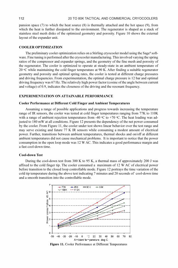
Cooler Performance at Different Cold Finger and Ambient Temperatures
Assuming a range of possible applications and progress towards increasing the temperature
range of IR sensors, the cooler was tested at cold finger temperatures ranging from 77K to 110K
with a range of ambient rejection temperatures from -40 oC to +70
oC. The heat loading was ad-
justed to 180 mW at all conditions. Figure 12 presents the dependency of the net power consumed
by the cooler. From Figure 11, the cooler under test shows linear behavior over the test range and
may serve existing and future 77 K IR sensors while consuming a modest amount of electrical
power. Further, transitions between ambient temperatures, thermal shocks and on/off at different
ambient temperatures did not cause mechanical problems. It is important to notice that the power
consumption in the open loop mode was 12 W AC. This indicates a good performance margin and
a fast cool-down time.
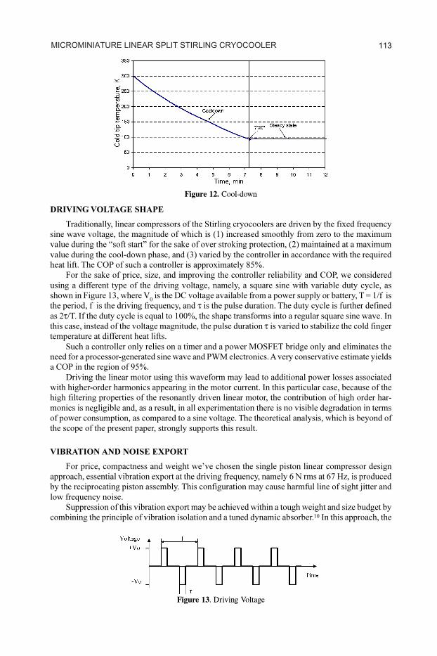
Cool-down Test
During the cool-down test from 300 K to 95 K, a thermal mass of approximately 200 J was
affixed to the cold finger tip. The cooler consumed a maximum of 12 W AC of electrical power
before transition to the closed loop controllable mode. Figure 12 portrays the time variation of the
cold tip temperature during the above test indicating 7 minutes and 20 seconds of´ cool-down time
and a smooth transition into the controllable mode.
Figure 11. Cooler Performance at Different Temperatures
20 TO 80K TACTICAL AND COMMERCIAL CRYOCOOLERS112
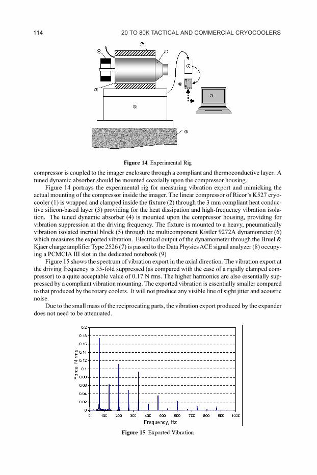
DRIVING VOLTAGE SHAPE
Traditionally, linear compressors of the Stirling cryocoolers are driven by the fixed frequency
sine wave voltage, the magnitude of which is (1) increased smoothly from zero to the maximum
value during the “soft start” for the sake of over stroking protection, (2) maintained at a maximum
value during the cool-down phase, and (3) varied by the controller in accordance with the required
heat lift. The COP of such a controller is approximately 85%.
For the sake of price, size, and improving the controller reliability and COP, we considered
using a different type of the driving voltage, namely, a square sine with variable duty cycle, as
shown in Figure 13, where V0
is the DC voltage available from a power supply or battery, T = 1/f is
the period, f is the driving frequency, and is the pulse duration. The duty cycle is further defined
as 2 T. If the duty cycle is equal to 100%, the shape transforms into a regular square sine wave. In
this case, instead of the voltage magnitude, the pulse duration is varied to stabilize the cold finger
temperature at different heat lifts.
Such a controller only relies on a timer and a power MOSFET bridge only and eliminates the
need for a processor-generated sine wave and PWM electronics. A very conservative estimate yields
a COP in the region of 95%.
Driving the linear motor using this waveform may lead to additional power losses associated
with higher-order harmonics appearing in the motor current. In this particular case, because of the
high filtering properties of the resonantly driven linear motor, the contribution of high order har-
monics is negligible and, as a result, in all experimentation there is no visible degradation in terms
of power consumption, as compared to a sine voltage. The theoretical analysis, which is beyond of
the scope of the present paper, strongly supports this result.
VIBRATION AND NOISE EXPORT
For price, compactness and weight we’ve chosen the single piston linear compressor design
approach, essential vibration export at the driving frequency, namely 6 N rms at 67 Hz, is produced
by the reciprocating piston assembly. This configuration may cause harmful line of sight jitter and
low frequency noise.
Suppression of this vibration export may be achieved within a tough weight and size budget by
combining the principle of vibration isolation and a tuned dynamic absorber.10
In this approach, the
Figure 12. Cool-down
Figure 13. Driving Voltage
MICROMINIATURE LINEAR SPLIT STIRLING CRYOCOOLER 113
compressor is coupled to the imager enclosure through a compliant and thermoconductive layer. A
tuned dynamic absorber should be mounted coaxially upon the compressor housing.
Figure 14 portrays the experimental rig for measuring vibration export and mimicking the
actual mounting of the compressor inside the imager. The linear compressor of Ricor’s K527 cryo-
cooler (1) is wrapped and clamped inside the fixture (2) through the 3 mm compliant heat conduc-
tive silicon-based layer (3) providing for the heat dissipation and high-frequency vibration isola-
tion. The tuned dynamic absorber (4) is mounted upon the compressor housing, providing for
vibration suppression at the driving frequency. The fixture is mounted to a heavy, pneumatically
vibration isolated inertial block (5) through the multicomponent Kistler 9272A dynamometer (6)
which measures the exported vibration. Electrical output of the dynamometer through the Bruel &
Kjaer charge amplifier Type 2526 (7) is passed to the Data Physics ACE signal analyzer (8) occupy-
ing a PCMCIA III slot in the dedicated notebook (9)
Figure 15 shows the spectrum of vibration export in the axial direction. The vibration export at
the driving frequency is 35-fold suppressed (as compared with the case of a rigidly clamped com-
pressor) to a quite acceptable value of 0.17 N rms. The higher harmonics are also essentially sup-
pressed by a compliant vibration mounting. The exported vibration is essentially smaller compared
to that produced by the rotary coolers. It will not produce any visible line of sight jitter and acoustic
noise.
Due to the small mass of the reciprocating parts, the vibration export produced by the expander
does not need to be attenuated.
Figure 14. Experimental Rig
Figure 15. Exported Vibration
20 TO 80K TACTICAL AND COMMERCIAL CRYOCOOLERS 114
PROJECT STATUS
The pilot cryocooler accumulated approximately 3000 hours of an irregular operating profile,
including on/offs and exposure to temperature extremes. The cryocooler design has been revised to
ease the assembly and maintenance. The new engineering series is planned for qualification testing
by the end of 2006.
REFERENCES
1. Gething, M.J., “Seeking the Heat in the Night,” Jane’s International Defense Review, Vol. 38, June
2005, pp. 42-47.
2. Glozman, A., et al., “High Performance InAlSb MWIR Detectors Operating at 100K and Beyond,”
Proceedings of SPIE, Volume 6206 - Infrared Technology and Applications XXXII, B.F. Andresen,
Gabor F. Fulop, Paul R. Norton, Editors, 2006.
3. Redlich, R., Unger, R., and Van der Walt, “Linear compressors: motor configuration, modulation and
systems,” International Compressor Engineering Conference, Purdue University, West Lafayette, IN,
(1996).
4. Marquardt, E., Radebaugh, R., and Kittel, P., “Design equations and scaling laws for linear compres-
sors with flexure springs,” 7th International Cryocooler Conference Proceedings, Air Force Phillips
Laboratory Report PL-CP--93-1001, Kirtland Air Force Base, NM, April 1993, pp. 783-804.
5. Koh, D.Y., Hong, Y.J., Park, S.J., Kim, H.B., and Lee, K.S.,“A study on the linear compressor charac-
teristics of the Stirling cryocooler,” Cryogenics, Vol. 42, Issue: 6-7 (June-July 2002) pp. 427–432
6. Narayankhedkar, K.G., Nagaraja, N., Bapat, S.L., and Patel, L.N., “Analysis of linear motor for elec-
tromagnetic driven cryocooler,” Proc. of International Conference on Cryogenics, Macmillian India
Ltd., New Delphi, India (1988), pp. 284-292.
7. Pollak, E., Friedlaender, F.J., Soedel, W., Cohen, R., “Mathematical model of an electrodynamic oscil-
lating refrigeration compressor,” Proc. of the Purdue Compressor Technology Conf., Purdue Univer-
sity, (1978), pp.246-259.
8. Kraus, J., and Fleisch, D., Electromagnetics: with Applications. McGraw-Hill Companies, Inc. (1999).
9. Gedeon, D., Sage Pulse Tube Model-Class Reference Guide, Gedeon Associates (1999).
10. Veprik, A.M., Babitsky, V.I., Pundak, N., Riabzev, S., “Vibration protection of critical components of
infrared equipment,” Journal of Shock and Vibration, Vol. 8, No. 1 (2001).
MICROMINIATURE LINEAR SPLIT STIRLING CRYOCOOLER 115