micropilot m fmr250 - endress+hauser · 2010-07-30 · micropilot m fmr250 4 to 20 ma hart 2...
TRANSCRIPT

BA284F/00/EN/03.10
71112111
Valid as of software version:
01.05.00
Operating Instructions
Micropilot M FMR250Level-Radar

Micropilot M FMR250 4 to 20 mA HART
2 Endress+Hauser
Brief operating instructions
L00-FMR250xx-19-00-00-en-020
! Note!
This operating manual explains the installation and initial start-up for the level transmitter. All
functions that are required for a typical measuring task are taken into account here. In addition, the
Micropilot M provides many other functions that are not included in this operating manual, such as
optimising the measuring point and converting the measured values.
An overview of all device functions can be found on → ä 86.
The operating manual BA291F/00/EN "Description of Instrument Functions" provides an
extensive description of all device functions, which can be found on the enclosed CD-ROM.
E+-
+
E+- E
E
-
… …
…
KA235F/00/a2/08.0652025245
…
20 mA100%
4mA0%
D
L
F
E
52025245
Micropilot M FMR240/244/245/250 - Brief operating instructions
- domeceiling
- horizontalcyl.
- bypass…
- unknown- metal silo- concrete
silo- bin / bunker
…
- liquid
- solid
- unknown- DC: <1.9- DC: 1.9 … 4- DC: 4 … 10- DC: >10
- standard- calm
surface- add.
agitator…
input E(see sketch)
input E(see sketch)
input F(see sketch)
input F(see sketch)
only forbypass +stilling well
- ok- too small- too big- unknown- manual
displayed(see sketch)
D and L are confirm
or specifyrange
suggestion
000measuredvalue
Groupselection
00basicsetup
01safetysettings
0Csystem parameter
09display
0Eenvelopecurve
04linearisation
05extendedcalibr.
06output (HART, FF)profibus param. (PA)
092language
0Adiagnostics
0A0present error
002tankshape
002tankshape
00Avessel /silo
004processcond.
005emptycalibr.
005emptycalibr.
006fullcalibr.
006fullcalibr.
007pipediameter
008dist./meas value
051checkdistance
003mediumcond.
00Bmediumcond.
00Cproscesscond.
052range ofmapping
053startmapping
008dist./meas value
- envel. curve- incl. FAC- incl. cust. map
- single curve- cyclic
= 100: unlocked
100: locked≠
0E1plot settings
0E2recordingcurve
0A1previous error
0A4unlock parameter
HART}
Contrast: + or +
- unknown- DC: 1.6...1.9- DC: 1.9 …2.5- DC: 2.5 …4
...
- standard- fast change- slow change- test: no filter flange:
reference pointofmeasurement
threadedconnection1 ½” (R 1
:reference point ofmeasurement
BSPT ½”)or 1½ NPT
001mediatype
= 2457: unlocked
2457: locked≠ PA, FF}
Solid Liquid

Micropilot M FMR250 4 to 20 mA HART Table of contents
Endress+Hauser 3
Table of contents
1 Safety instructions . . . . . . . . . . . . . . . . 4
1.1 Designated use . . . . . . . . . . . . . . . . . . . . . . . . . . . . 4
1.2 Installation, commissioning and operation . . . . . . . . 4
1.3 Operational safety and process safety . . . . . . . . . . . . 4
1.4 Notes on safety conventions and symbols . . . . . . . . . 5
2 Identification . . . . . . . . . . . . . . . . . . . . 6
2.1 Device designation . . . . . . . . . . . . . . . . . . . . . . . . . 6
2.2 Scope of delivery . . . . . . . . . . . . . . . . . . . . . . . . . . . 9
2.3 Certificates and approvals . . . . . . . . . . . . . . . . . . . . 9
2.4 Registered trademarks . . . . . . . . . . . . . . . . . . . . . . . 9
3 Installation . . . . . . . . . . . . . . . . . . . . . 10
3.1 Quick installation guide . . . . . . . . . . . . . . . . . . . . . 10
3.2 Incoming acceptance, transport, storage . . . . . . . . . 10
3.3 Installation conditions . . . . . . . . . . . . . . . . . . . . . . 11
3.4 Installation instructions . . . . . . . . . . . . . . . . . . . . . 20
3.5 Post-installation check . . . . . . . . . . . . . . . . . . . . . . 25
4 Wiring . . . . . . . . . . . . . . . . . . . . . . . . 26
4.1 Quick wiring guide . . . . . . . . . . . . . . . . . . . . . . . . 26
4.2 Connecting the measuring unit . . . . . . . . . . . . . . . 28
4.3 Recommended connection . . . . . . . . . . . . . . . . . . 31
4.4 Degree of protection . . . . . . . . . . . . . . . . . . . . . . . 31
4.5 Post-connection check . . . . . . . . . . . . . . . . . . . . . . 31
5 Operation . . . . . . . . . . . . . . . . . . . . . . 32
5.1 Quick operation guide . . . . . . . . . . . . . . . . . . . . . . 32
5.2 Display and operating elements . . . . . . . . . . . . . . . 34
5.3 Local operation . . . . . . . . . . . . . . . . . . . . . . . . . . . 36
5.4 Display and acknowledging error messages . . . . . . 39
5.5 HART communication . . . . . . . . . . . . . . . . . . . . . . 40
6 Commissioning. . . . . . . . . . . . . . . . . . 43
6.1 Function check . . . . . . . . . . . . . . . . . . . . . . . . . . . 43
6.2 Switching on the measuring device . . . . . . . . . . . . 43
6.3 Basic Setup . . . . . . . . . . . . . . . . . . . . . . . . . . . . . . 44
6.4 Basic Setup with the device display . . . . . . . . . . . . 46
6.5 Basic Setup with the
Endress+Hauser operating program . . . . . . . . . . . . 58
7 Maintenance. . . . . . . . . . . . . . . . . . . . 62
8 Accessories. . . . . . . . . . . . . . . . . . . . . 63
8.1 Weather protection cover . . . . . . . . . . . . . . . . . . . 63
8.2 Commubox FXA195 HART . . . . . . . . . . . . . . . . . . 63
8.3 Commubox FXA291 . . . . . . . . . . . . . . . . . . . . . . . 63
8.4 ToF Adapter FXA291 . . . . . . . . . . . . . . . . . . . . . . . 63
8.5 Remote display FHX40 . . . . . . . . . . . . . . . . . . . . . 64
8.6 Horn cover for 80 mm (3") and 100 mm (4")
horn antenna . . . . . . . . . . . . . . . . . . . . . . . . . . . . . 65
9 Trouble-shooting . . . . . . . . . . . . . . . . . 67
9.1 Trouble-shooting instructions . . . . . . . . . . . . . . . . . 67
9.2 System error messages . . . . . . . . . . . . . . . . . . . . . . 68
9.3 Application errors in liquids . . . . . . . . . . . . . . . . . . 70
9.4 Application errors in solids . . . . . . . . . . . . . . . . . . . 72
9.5 Orientation of the Micropilot . . . . . . . . . . . . . . . . . 74
9.6 Spare Parts . . . . . . . . . . . . . . . . . . . . . . . . . . . . . . 76
9.7 Return . . . . . . . . . . . . . . . . . . . . . . . . . . . . . . . . . . 77
9.8 Disposal . . . . . . . . . . . . . . . . . . . . . . . . . . . . . . . . . 77
9.9 Software history . . . . . . . . . . . . . . . . . . . . . . . . . . . 77
9.10 Contact addresses of Endress+Hauser . . . . . . . . . . . 77
10 Technical data . . . . . . . . . . . . . . . . . . . 78
10.1 Additional technical data . . . . . . . . . . . . . . . . . . . . 78
11 Appendix. . . . . . . . . . . . . . . . . . . . . . . 86
11.1 Operating menu HART . . . . . . . . . . . . . . . . . . . . . 86
11.2 Patents . . . . . . . . . . . . . . . . . . . . . . . . . . . . . . . . . 88
Index . . . . . . . . . . . . . . . . . . . . . . . . . . . . . . 89

Safety instructions Micropilot M FMR250 4 to 20 mA HART
4 Endress+Hauser
1 Safety instructions
1.1 Designated use
The Micropilot M is a compact level radar for the continuous, contactless measurement of
predominantly solids. The device can also be freely mounted outside closed metal vessels because
of its operating frequency of about 26 GHz and a maximum radiated pulsed energy of 1 mW
(average power output 1 μW). Operation is completely harmless to humans and animals.
1.2 Installation, commissioning and operation
The Micropilot M has been designed to operate safely in accordance with current technical, safety
and EU standards. If installed incorrectly or used for applications for which it is not intended,
however, it is possible that application-related dangers may arise, e.g. product overflow due to
incorrect installation or calibration. For this reason, the instrument must be installed, connected,
operated and maintained according to the instructions in this manual: personnel must be authorised
and suitably qualified. The manual must have been read and understood, and the instructions
followed. Modifications and repairs to the device are permissible only when they are expressly
approved in the manual.
1.3 Operational safety and process safety
Alternative monitoring measures must be taken to ensure operational safety and process safety
during configuration, testing and maintenance work on the device.
1.3.1 Hazardous areas
Measuring systems for use in hazardous environments are accompanied by separate "Ex
documentation", which is an integral part of this Operating Manual. Strict compliance with the
installation instructions and ratings as stated in this supplementary documentation is mandatory.
• Ensure that all personnel are suitably qualified.
• Observe the specifications in the certificate as well as national and local standards and regulations.
1.3.2 FCC approval
This device complies with part 15 of the FCC Rules. Operation is subject to the following two
conditions:
1. This device may not cause harmful interference, and
2. this device must accept any interference received, including interference that may cause
undesired operation.
" Caution!
Changes or modifications not expressly approved by the part responsible for
compliance could void the user’s authority to operate the equipment.

Micropilot M FMR250 4 to 20 mA HART Safety instructions
Endress+Hauser 5
1.4 Notes on safety conventions and symbols
In order to highlight safety-relevant or alternative operating procedures in the manual, the following
conventions have been used, each indicated by a corresponding symbol in the margin.
Safety conventions
#Warning!
A warning highlights actions or procedures which, if not performed correctly, will lead to personal
injury, a safety hazard or destruction of the instrument.
"Caution!
Caution highlights actions or procedures which, if not performed correctly, may lead to personal
injury or incorrect functioning of the instrument.
!Note!
A note highlights actions or procedures which, if not performed correctly, may indirectly affect
operation or may lead to an instrument response which is not planned.
Explosion protection
0Device certified for use in explosion hazardous area
If the device has this symbol embossed on its name plate it can be installed in an explosion hazardous
area.
-Explosion hazardous area
Symbol used in drawings to indicate explosion hazardous areas. Devices located in and wiring
entering areas with the designation “explosion hazardous areas” must conform with the stated type
of protection.
.Safe area (non-explosion hazardous area)
Symbol used in drawings to indicate, if necessary, non-explosion hazardous areas. Devices located in
safe areas still require a certificate if their outputs run into explosion hazardous areas.
Electrical symbols
% Direct voltage
A terminal to which or from which a direct current or voltage may be applied or supplied.
&Alternating voltage
A terminal to which or from which an alternating (sine-wave) current or voltage may be applied or
supplied.
)Grounded terminal
A grounded terminal, which as far as the operator is concerned, is already grounded by means of an
earth grounding system.
*Protective grounding (earth) terminal
A terminal which must be connected to earth ground prior to making any other connection to the
equipment.
+Equipotential connection (earth bonding)
A connection made to the plant grounding system which may be of type e.g. neutral star or
equipotential line according to national or company practice.
Temperature resistance of the connection cables
States, that the connection cables must be resistant to a temperature of at least 85 °C (185 °F).t >85°C

Identification Micropilot M FMR250 4 to 20 mA HART
6 Endress+Hauser
2 Identification
2.1 Device designation
2.1.1 Nameplate
The following technical data are given on the instrument nameplate:
Typenschild-FMxxxx-xx
Information on the nameplate of the Micropilot M
1 Instrument designation
2 Order code
3 Serial number
4 Process pressure
5 Process temperature
6 Length (optional)
7 Power supply
8 Current supply
9 Ambient temperature
10 Cable specification
11 Factory sealed
12 Radio equipment number
13 TÜV identification mark
14 Certificate symbol (optional) e.g. Ex, NEPSI
15 ertificate symbol (optional) e.g. 3A
16 Certificate symbol (optional) e.g. SIL, FF
17 Place of production
18 Degree of protection e.g. IP65, IP67
19 Certificates and approvals
20 Document number of safety instructions e.g. XA, ZD, ZE
21 Dat./Insp. xx / yy (xx = week of production, yy = year of production)
ENDRESS+HAUSER
Order Code:
Ser.-No.:
Dat./Insp.:
if modificationsee sep. labelX =
1
2
3
45
7
8
9 10 11
12
13 14 15
6
16
17
18
19
20
21
Micropilot M FMR250 4 to 20 mA HART Identification
Endress+Hauser 7
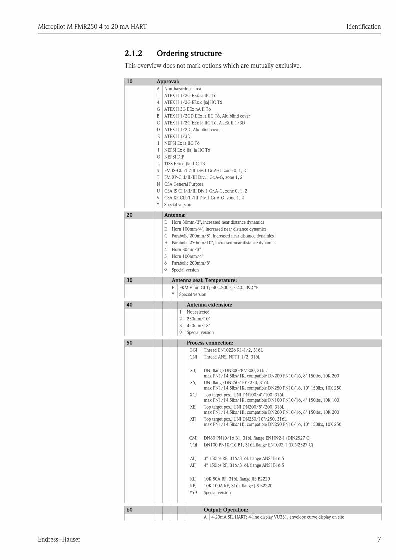
2.1.2 Ordering structure
This overview does not mark options which are mutually exclusive.
10 Approval:
A Non-hazardous area
1 ATEX II 1/2G EEx ia IIC T6
4 ATEX II 1/2G EEx d [ia] IIC T6
G ATEX II 3G EEx nA II T6
B ATEX II 1/2GD EEx ia IIC T6, Alu blind cover
C ATEX II 1/2G EEx ia IIC T6, ATEX II 1/3D
D ATEX II 1/2D, Alu blind cover
E ATEX II 1/3D
I NEPSI Ex ia IIC T6
J NEPSI Ex d (ia) ia IIC T6
Q NEPSI DIP
L TISS EEx d (ia) IIC T3
S FM IS-Cl.I/II/III Div.1 Gr.A-G, zone 0, 1, 2
T FM XP-Cl.I/II/III Div.1 Gr.A-G, zone 1, 2
N CSA General Purpose
U CSA IS Cl.I/II/III Div.1 Gr.A-G, zone 0, 1, 2
V CSA XP Cl.I/II/III Div.1 Gr.A-G, zone 1, 2
Y Special version
20 Antenna:
D Horn 80mm/3", increased near distance dynamics
E Horn 100mm/4", increased near distance dynamics
G Parabolic 200mm/8", increased near distance dynamics
H Parabolic 250mm/10", increased near distance dynamics
4 Horn 80mm/3"
5 Horn 100mm/4"
6 Parabolic 200mm/8"
9 Special version
30 Antenna seal; Temperature:
E FKM Viton GLT; -40...200°C/-40...392 °F
Y Special version
40 Antenna extension:
1 Not selected
2 250mm/10"
3 450mm/18"
9 Special version
50 Process connection:
GGJ Thread EN10226 R1-1/2, 316L
GNJ Thread ANSI NPT1-1/2, 316L
X3J UNI flange DN200/8"/200, 316L
max PN1/14.5lbs/1K, compatible DN200 PN10/16, 8" 150lbs, 10K 200
X5J UNI flange DN250/10"/250, 316L
max PN1/14.5lbs/1K, compatible DN250 PN10/16, 10" 150lbs, 10K 250
XCJ Top target pos., UNI DN100/4"/100, 316L
max PN1/14.5lbs/1K, compatible DN100 PN10/16, 4" 150lbs, 10K 100
XEJ Top target pos., UNI DN200/8"/200, 316L
max PN1/14.5lbs/1K, compatible DN200 PN10/16, 8" 150lbs, 10K 200
XFJ Top target pos., UNI DN250/10"/250, 316L
max PN1/14.5lbs/1K, compatible DN250 PN10/16, 10" 150lbs, 10K 250
CMJ DN80 PN10/16 B1, 316L flange EN1092-1 (DIN2527 C)
CQJ DN100 PN10/16 B1, 316L flange EN1092-1 (DIN2527 C)
ALJ 3" 150lbs RF, 316/316L flange ANSI B16.5
APJ 4" 150lbs RF, 316/316L flange ANSI B16.5
KLJ 10K 80A RF, 316L flange JIS B2220
KPJ 10K 100A RF, 316L flange JIS B2220
YY9 Special version
60 Output; Operation:
A 4-20mA SIL HART; 4-line display VU331, envelope curve display on site

Identification Micropilot M FMR250 4 to 20 mA HART
8 Endress+Hauser
B 4-20mA SIL HART; w/o display, via communication
K 4-20mA SIL HART; prepared for FHX40, remote display (Accessory)
C PROFIBUS PA; 4-line display VU331, envelope curve display on site
D PROFIBUS PA; w/o display, via communication
L PROFIBUS PA; prepared for FHX40, remote display (Accessory)
E FOUNDATION Fieldbus; 4-line display, envelope curve display on site
F FOUNDATION Fieldbus; w/o display, via communication
M FOUNDATION Fieldbus; prepared for FHX40, remote display (Accessory)
Y Special version
70 Housing:
A F12 Alu, coated IP65 NEMA4X
B F23 316L IP65 NEMA4X
C T12 Alu, coated IP65 NEMA4X, separate connection compartment
D T12 Alu, coated IP65 NEMA4X + OVP, separate connection compartment,
OVP = overvoltage protection
Y Special version
80 Cable entry:
2 Gland M20 (EEx d > thread M20)
3 Thread G1/2
4 Thread NPT1/2
9 Special version
90 Additional option:
K Air purge connection G1/4
M Air purge connection NPT1/4
P 5-point, Air purge connection G1/4
5-point linearity protocol, see additional spec.
Q 5-point, Air purge connection NPT1/4
5-point linearity protocol, see additional spec.
Y Special version
995 Marking:
1 Tagging (TAG)
2 Bus address
FMR250- Complete product designation
60 Output; Operation:
Micropilot M FMR250 4 to 20 mA HART Identification
Endress+Hauser 9
2.2 Scope of delivery
" Caution!
It is essential to follow the instructions concerning the unpacking, transport and storage of
measuring instruments given in the chapter "Incoming acceptance, transport, storage", → ä 10!
The scope of delivery consists of:
• Assembled instrument
• Accessories (→ ä 63)
• Endress+Hauser operating program on the enclosed CD-ROM
• Brief operating instructions KA1015F/00/EN for quick commissioning
• Brief operating instructions KA235F/00/A2 (basic setup/trouble shooting), housed in the
instrument
• Approval documentation: if this is not included in the operating manual
• CD-ROM with further documentation, e. g.
– Technical Information
– Operating Instruction
– Description of Instrument Functions
2.3 Certificates and approvals
CE mark, declaration of conformity
The device is designed to meet state-of-the-art safety requirements, has been tested and left the
factory in a condition in which it is safe to operate. The device complies with the applicable
standards and regulations as listed in the EC declaration of conformity and thus complies with the
statutory requirements of the EG directives. Endress+Hauser confirms the successful testing of the
device by affixing to it the CE mark.
2.4 Registered trademarks
KALREZ®, VITON®, TEFLON®
Registered trademark of the company, E.I. Du Pont de Nemours & Co., Wilmington, USA
TRI-CLAMP®
Registered trademark of the company, Ladish & Co., Inc., Kenosha, USA
HART®
Registered trademark of HART Communication Foundation, Austin, USA
ToF®
Registered trademark of the company Endress+Hauser GmbH+Co. KG, Maulburg, Germany
PulseMaster®
Registered trademark of the company Endress+Hauser GmbH+Co. KG, Maulburg, Germany
PhaseMaster®
Registered trademark of the company Endress+Hauser GmbH+Co. KG, Maulburg, Germany

Installation Micropilot M FMR250 4 to 20 mA HART
10 Endress+Hauser
3 Installation
3.1 Quick installation guide
L00-FMR250xx-17-00-00-en-011
3.2 Incoming acceptance, transport, storage
3.2.1 Incoming acceptance
Check the packing and contents for any signs of damage.
Check the shipment, make sure nothing is missing and that the scope of supply matches your order.
3.2.2 Transport
" Caution!
Follow the safety instructions and transport conditions for instruments of more than
18 kg (39.69 lbs). Do not lift the measuring instrument by its housing in order to transport it.
3.2.3 Storage
Pack the measuring instrument so that is protected against impacts for storage and transport. The
original packing material provides the optimum protection for this.
The permissible storage temperature is -40 °C to +80 °C (-40 °F to +176 °F) or
-50 °C to +80 °C (+58 °F to +176 °F).
DN80…200ANSI 3…8”
3 3
1 1
22
#
90°
90°
90°
90°
90°90°
F12/F23 housing T12 housing
Turn housing
At mounting adjust the marking at the instrument flange!
Installation in vessel (free space):Mark on process connector facing the nearest vessel wall!
The housing can be turned 350° in order to simplify access to thedisplay and the terminal compartment
Allen key 4 mm (0.16 in)
1½” BSPT (R1½”),or
1½NPT
mark at instrument flangeor threaded boss
Note!At version with top target positioner, the marker is at the housing adapter(opposite the air purge connection).

Micropilot M FMR250 4 to 20 mA HART Installation
Endress+Hauser 11
3.3 Installation conditions
3.3.1 Dimensions
Housing dimensions
L00-F12xxxx-06-00-00-en-001
L00-T12xxxx-06-00-00-en-001
L00-F23xxxx-06-00-00-en-001
ENDRESS+HAUSER
65 (2.56) 78 (3.07)max. 110 (4.33)
mm (in)
85 (3.35)
150 (
5.9
1)
ø129 (
ø5.0
8)
(Aluminium)F12 housing
ENDRESS+HAUSER
78 (3.07)
85 (3.35)
65 (2.56)
162 (
6.3
8)
max. 100 (4.33) 94 (3.7)
mm (in)
ø129 (
ø5.0
8)
(Aluminium)T12 housing
max. 94 (3.7)
mm (in)
93 (3.66)
ø129 (
ø5.0
8)
150 (
5.9
1)
40 (
1.5
7)
(316L)F23 housing
Installation Micropilot M FMR250 4 to 20 mA HART
12 Endress+Hauser
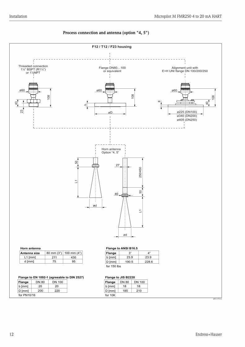
Process connection and antenna (option "4, 5")
a0011475-en
L1
L1
50
50
10
8
40
10
8
10
8
ød
ød
40
27
25
0/4
50
75
211
80 mm (3”)
95
430
100 mm (4”)
b [mm] b [mm]
b [mm]
DN 80 DN 80
3”
20 18
23.9
200 185
190.5
L1 [mm]
d [mm]
D [mm] D [mm]
D [mm]
220 210
228.6
20 18
23.9
DN 100 DN 100
4”
øD ø225 (DN100)
340 (DN200)ø
ø405 (DN250)
43
b
8
23
ø60ø60ø60
Horn antennaOption “4, 5”
for 10K
Flange
Flange to JIS B2220
for 150 lbs
Flange
Flange to ANSI B16.5
for PN10/16
Antenna size
Horn antenna
Flange
Flange to EN 1092-1 (agreeable to DIN 2527)
F12 / T12 / F23 housing
Threaded connectionBSPT (R1½”)
or 1½NPT1½”
Flange DN80…100or equivalent
Alignment unit withE+H UNI flange DN 100/200/250
Micropilot M FMR250 4 to 20 mA HART Installation
Endress+Hauser 13
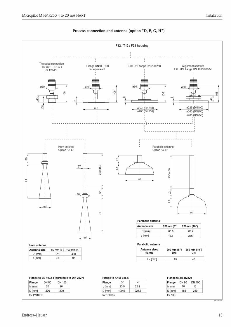
Process connection and antenna (option "D, E, G, H")
a0011476-en
250 mm (10”)UNI
200 mm (8”)UNI
50L2 [mm] 37
250mm (10”)
236
88.4
200mm (8”)
173
60.6L1 [mm]
d [mm]
L1
L2
L1
L2
250/4
50
ød
L1
L1
ød
50
50
250/4
50
ød
ød
75
211
80 mm (3”)
95
430
100 mm (4”)
b [mm] b [mm]b [mm]
DN 80 DN 803”
20 1823.9
200 185190.5
L1 [mm]
d [mm]
D [mm] D [mm]D [mm]220 210228.6
20 1823.9
DN 100 DN 1004”
40
27
108
40
108
108
108
øD ø340 (DN200)ø405 (DN250)
ø225 (DN100)
340 (DN200)ø
ø405 (DN250)
43
b
8 8
23
ø60ø60ø60ø60
Antenna size
Parabolic antenna
Antenna size /flange
Parabolic antenna
Parabolic antennaOption “G, H”
Horn antennaOption “D, E”
for 10K
Flange
Flange to JIS B2220
for 150 lbs
Flange
Flange to ANSI B16.5
for PN10/16
Antenna size
Horn antenna
Flange
Flange to EN 1092-1 (agreeable to DIN 2527)
F12 / T12 / F23 housing
Threaded connectionBSPT (R1½”)or 1½NPT
1½” Flange DN80…100or equivalent
E+H UNI flange DN 200/250 Alignment unit withE+H UNI flange DN 100/200/250
Installation Micropilot M FMR250 4 to 20 mA HART
14 Endress+Hauser
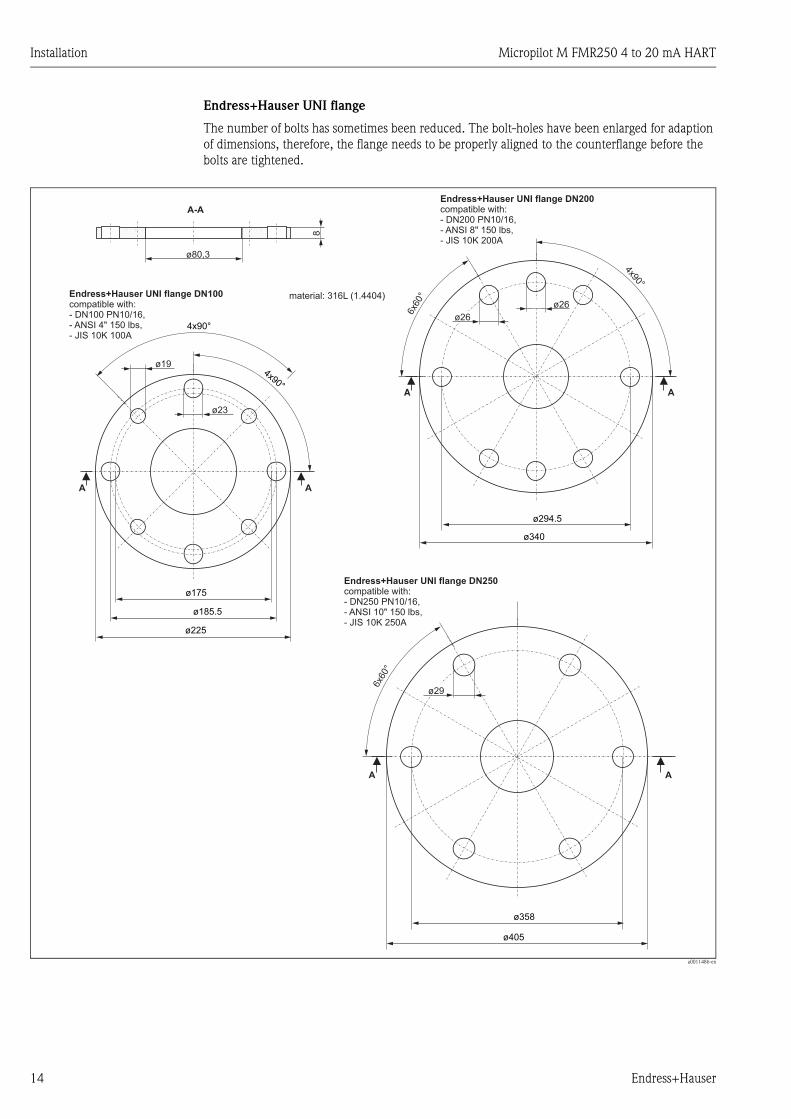
Endress+Hauser UNI flange
The number of bolts has sometimes been reduced. The bolt-holes have been enlarged for adaption
of dimensions, therefore, the flange needs to be properly aligned to the counterflange before the
bolts are tightened.
a0011486-en
ø175
4x90°
4x90°
ø225
ø19
ø23
A
A
A
A
A
A
A-A
8
ø340
ø405
4x90°
6x6
0°
6x6
0°
ø26
ø26
ø29
ø358
ø294.5
ø185.5
ø80,3
Endress+Hauser UNI flange DN100compatible with:- DN100 PN10/16,- ANSI 4" 150 lbs,- JIS 10K 100A
Endress+Hauser UNI flange DN200compatible with:- DN200 PN10/16,- ANSI 8" 150 lbs,- JIS 10K 200A
Endress+Hauser UNI flange DN250compatible with:- DN250 PN10/16,- ANSI 10" 150 lbs,- JIS 10K 250A
material: 316L (1.4404)
Micropilot M FMR250 4 to 20 mA HART Installation
Endress+Hauser 15
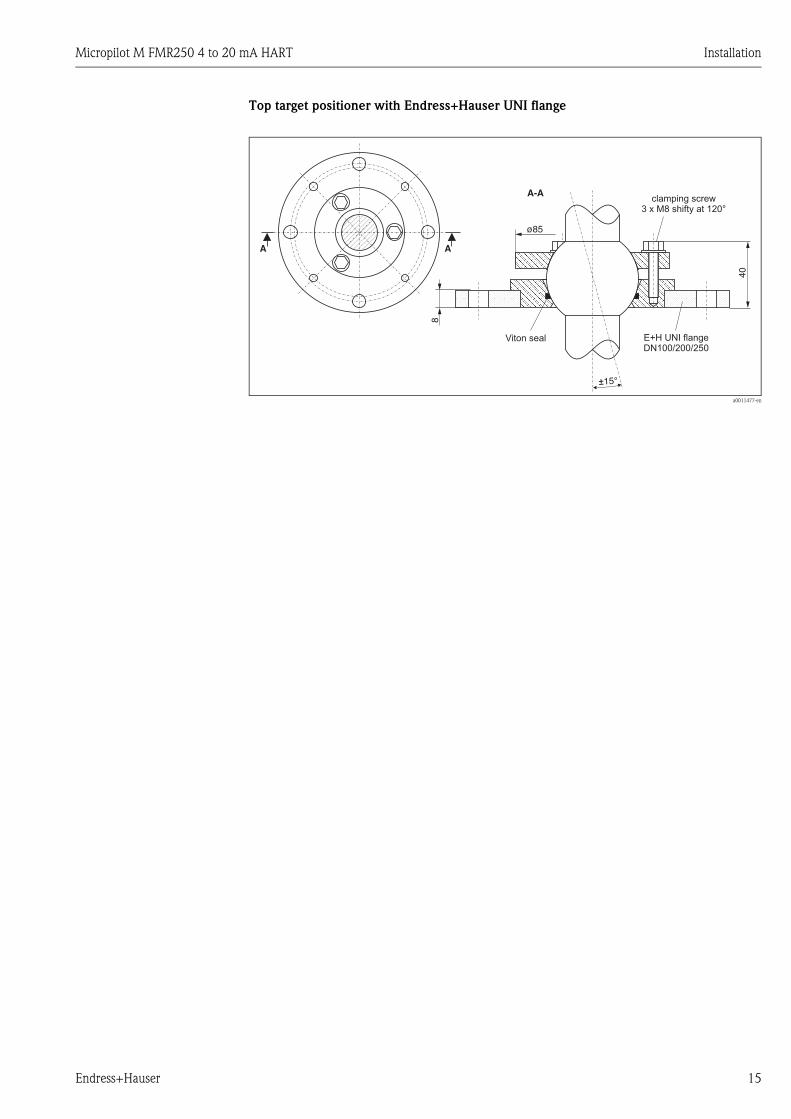
Top target positioner with Endress+Hauser UNI flange
a0011477-en
A
A-A
A
±15°
8
40
ø85
E+H UNI flangeDN100/200/250
clamping screw3 x M8 shifty at 120°
Viton seal
Installation Micropilot M FMR250 4 to 20 mA HART
16 Endress+Hauser
3.3.2 Engineering hints
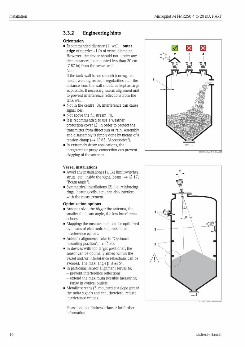
Orientation
• Recommended distance (1) wall – outer
edge of nozzle: ~1/6 of vessel diameter.
However, the device should not, under any
circumstances, be mounted less than 20 cm
(7.87 in) from the vessel wall.
Note!
If the tank wall is not smooth (corrugated
metal, welding seams, irregularities etc.) the
distance from the wall should be kept as large
as possible. If necessary, use an alignment unit
to prevent interference reflections from the
tank wall.
• Not in the centre (3), interference can cause
signal loss.
• Not above the fill stream (4).
• It is recommended to use a weather
protection cover (2) in order to protect the
transmitter from direct sun or rain. Assembly
and disassembly is simply done by means of a
tension clamp (→ ä 63, "Accessories").
• In extremely dusty applications, the
integrated air purge connection can prevent
clogging of the antenna.L00-FMR250xx-17-00-00-xx-003
1
2 3 4
Vessel installations
• Avoid any installations (1), like limit switches,
struts, etc., inside the signal beam (→ ä 17,
"Beam angle").
• Symmetrical installations (2), i.e. reinforcing
rings, heating coils, etc., can also interfere
with the measurement.
Optimization options
• Antenna size: the bigger the antenna, the
smaller the beam angle, the less interference
echoes.
• Mapping: the measurement can be optimized
by means of electronic suppression of
interference echoes.
• Antenna alignment: refer to "Optimum
mounting position", → ä 20.
• In devices with top target positioner, the
sensor can be optimally aimed within the
vessel and/or interference reflections can be
avoided. The max. angle β is ±15°.
• In particular, sensor alignment serves to:
– prevent interference reflections
– extend the maximum possible measuring
range in conical outlets.
• Metallic screens (3) mounted at a slope spread
the radar signals and can, therefore, reduce
interference echoes.
Please contact Endress+Hauser for further
information.
L00-FMR250xx-17-00-00-xx-002
1
2
a
b
3

Micropilot M FMR250 4 to 20 mA HART Installation
Endress+Hauser 17
Measurement in a plastic tank
If the outer wall of the tank is made of a non-conductive material (e.g. GRP), microwaves can also
be reflected off interfering installations outside the signal beam (e.g. metallic pipes (1), ladders (2),
grates (3), …). Therefore, there should be no such interfering installations in the signal beam.
Please contact Endress+Hauser for further information.
L00-FMR250xx-17-00-00-xx-014
Beam angle
The beam angle is defined as the angle α where the energy density of the radar waves reaches half
the value of the maximum energy density (3dB-width). Microwaves are also emitted outside the
signal beam and can be reflected off interfering installations. Beam diameter W as function of
antenna type (beam angle α) and measuring distance D:
VH
00
VH
00
Endress+Hauser
Endress+Hauser
- + V H
ENDRESS+HAUSERMICROPILOT II
IP 65
Order Code:Ser.-No.:
MessbereichMeasuring rangeU 16...36 V DC4...20 mA
max. 20 m
Mad
e in
Ger
man
y
M
aulb
urg
Mad
e in
Ger
man
y
M
aulb
urg
T >70°C :At >85°C
VH
00
VH
00
Endress+Hauser
Endress+Hauser
- + V H
ENDRESS+HAUSERMICROPILOT II
IP 65
Order Code:Ser.-No.:
MessbereichMeasuring rangeU 16...36 V DC4...20 mA
max. 20 m
Mad
e in
Ger
man
y
M
aulb
urg
Mad
e in
Ger
man
y
M
aulb
urg
T >70°C :At >85°C
1
2 3
VH
00
VH
00
Endress+Hauser
Endress+Hauser
- + V H
ENDRESS+HAUSERMICROPILOT II
IP 65
Order Code:Ser.-No.:
MessbereichMeasuring rangeU 16...36 V DC4...20 mA
max. 20 m
Mad
e in
Ger
man
y
M
aulb
urg
Mad
e in
Ger
man
y
M
aulb
urg
T >70°C :At >85°C
Antenna sizeHorn antenna Parabolic antenna
L00-FMR2xxxx-14-00-06-de-027
80 mm (3") 100 mm (4") 200 mm (8") 250 mm (10")
Beam angle α 10° 8° 4° 3.5°
Measuring
distance (D)
Beamwidth diameter (W)
80 mm (3") 100 mm (4") 200 mm (8") 250 mm (10")
5 m (16 ft) 0,87 m (2.9 ft) 0,70 m (2.3 ft) 0,35 m (1.1 ft) 0,3 m (1 ft)
10 m (33 ft) 1,75 m (5.7 ft) 1,40 m (4.6 ft) 0,70 m (2.3 ft) 0,61 m (2 ft)
15 m (49 ft) 2,62 m (8.6 ft) 2,10 m (6.9 ft) 1,05 m (3.4 ft) 0,92 m (3 ft)
20 m (66 ft) 3,50 m (11 ft) 2,80 m (9.2 ft) 1,40 m (4.6 ft) 1,22 m (4 ft)
30 m (98 ft) 5,25 m (17 ft) 4,20 m (14 ft) 2,10 m (6.9 ft) 1,83 m (6 ft)
40 m (131 ft) 7,00 m (23 ft) 5,59 m (18 ft) 2,79 m (9.2 ft) 2,44 m (8 ft)
50 m (164 ft) 8,75 m (29 ft) 6,99 m (23 ft) 3,50 m (11 ft) 3,06 m (10 ft)
aD
W
aD _=
22 . . tanW

Installation Micropilot M FMR250 4 to 20 mA HART
18 Endress+Hauser
Measuring conditions
• The measuring range begins, where the beam hits the bottom. Particularly with conical outlets
the level cannot be detected below this point. The maximum measuring range can be increased
in such applications by using top target positioner (→ ä 16).
• In case of media with a low dielectric constant (groups A and B), the bottom can be visible through
the medium at low levels. In order to guarantee the required accuracy in these cases, it is
recommended to position the zero-point at a distance C above the bottom (see Fig.).
• In principle it is possible to measure up to the tip of the antenna with the FMR250. However, due
to considerations regarding abrasion and build-up and depending on the orientation of the
product surface (angel of repose), the end of the measuring range should be at a distance of A (see
Fig.). If required, and if some conditions (high DC value, flat angle of repose) are met, shorter
distances can be achieved.
L00-FMR250xx-17-00-00-en-001
A [mm (in)] C [mm (in)]
approx. 400 (15.7) 50 to 150 (1.97 to 5.91)
100%
0%
A
C
Me
asu
rin
g r
an
ge
Micropilot M FMR250 4 to 20 mA HART Installation
Endress+Hauser 19
Measuring range
The usable measuring range depends on the size of the antenna, the reflectivity of the medium, the
mounting location and eventual interference reflections. The maximum configurable range is 70 m
(230 ft).
To achieve an optimised Signal strength it is recommended to use an antenna with as large as
possible diameter (DN200 (8") parabolic antenna, DN100 (4") horn).
Reduction of the max. possible measuring range through:
• Media with poor reflection properties (= small DC). For examples refer to table below.
• Angle of repose.
• Extremely loose surfaces of bulk solids, e.g. bulk solids with low bulk weight for pneumatic filling.
• Build-up, above all of moist products.
The following table describes the media groups and the dielectric constant εr.
The respective lower group applies for very loose or loosened bulk solids.
Media group DC (εr) Examples Signal attenuation
A 1.6 to 1.9
– Plastic granulate
– White lime, special cement
– Sugar
19 to 16 dB
B 1.9 to 2.5 – Portland cement, plaster 16 to 13 dB
C 2.5 to 4
– Grain, seeds
– Ground stones
– Sand
13 to 10 dB
D 4 to 7– Naturally moist (ground) stones, ores
– Salt10 to 7 dB
E > 7
– Metallic powder
– Carbon black
– Coal
< 7 dB
Installation Micropilot M FMR250 4 to 20 mA HART
20 Endress+Hauser
3.4 Installation instructions
3.4.1 Mounting kit
In addition to the tool needed for flange mounting, you will require the following tool:
• A key AF60 for threaded boss
• 4 mm (0.16 in) Allen wrench for turning the housing.
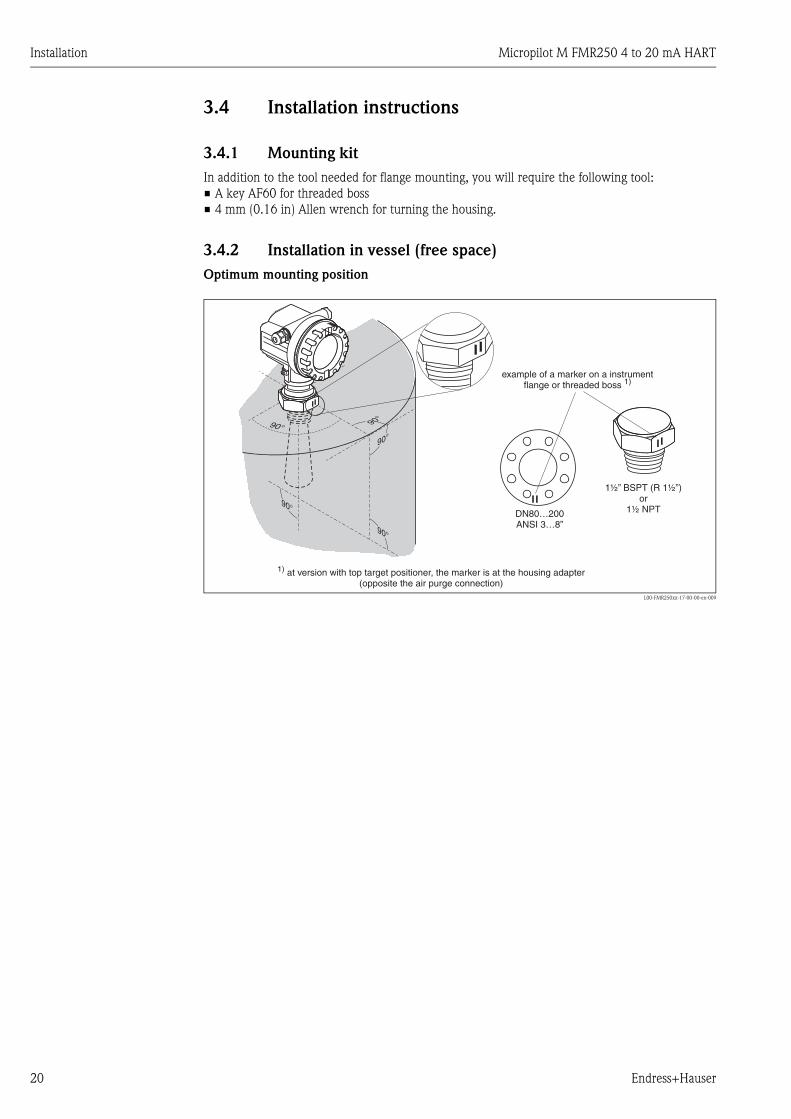
3.4.2 Installation in vessel (free space)
Optimum mounting position
L00-FMR250xx-17-00-00-en-009
90°
90°
90°
90°DN80…200ANSI 3…8”
90°
1½” BSPT (R 1½”)or
1½ NPT
example of a marker on a instrumentflange or threaded boss 1)
1) at version with top target positioner, the marker is at the housing adapter(opposite the air purge connection)
Micropilot M FMR250 4 to 20 mA HART Installation
Endress+Hauser 21
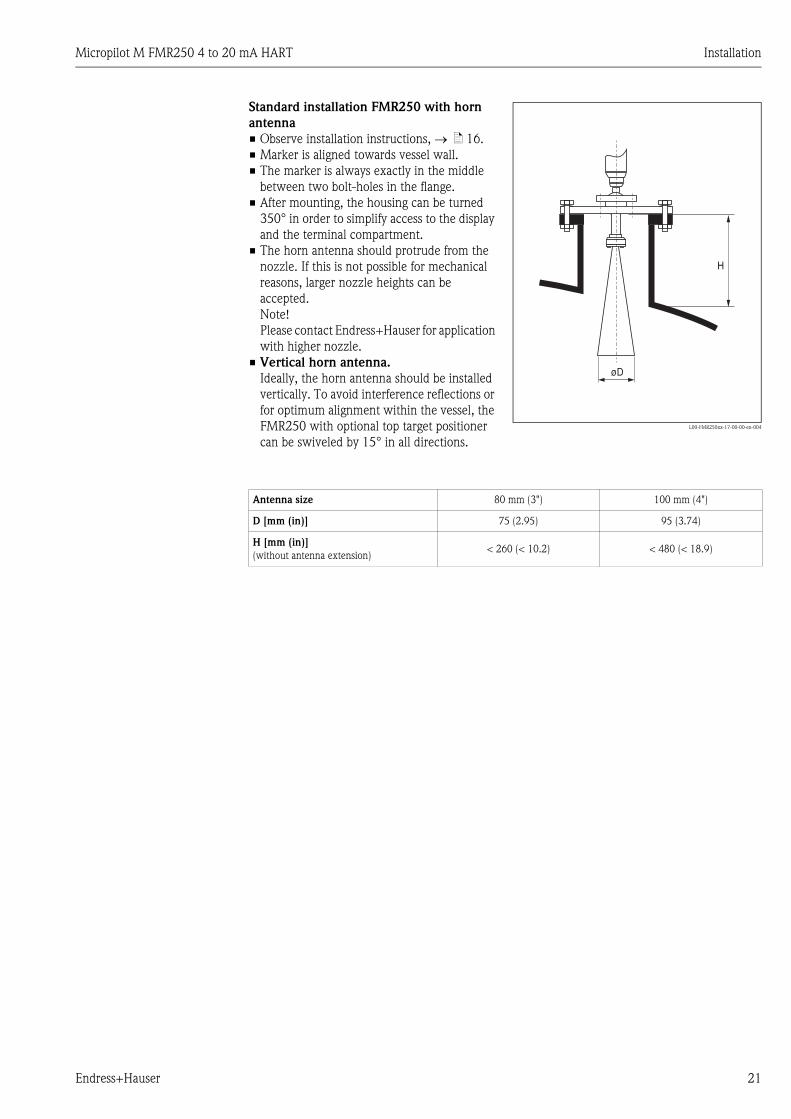
Standard installation FMR250 with horn
antenna
• Observe installation instructions, → ä 16.
• Marker is aligned towards vessel wall.
• The marker is always exactly in the middle
between two bolt-holes in the flange.
• After mounting, the housing can be turned
350° in order to simplify access to the display
and the terminal compartment.
• The horn antenna should protrude from the
nozzle. If this is not possible for mechanical
reasons, larger nozzle heights can be
accepted.
Note!
Please contact Endress+Hauser for application
with higher nozzle.
• Vertical horn antenna.
Ideally, the horn antenna should be installed
vertically. To avoid interference reflections or
for optimum alignment within the vessel, the
FMR250 with optional top target positioner
can be swiveled by 15° in all directions.
L00-FMR250xx-17-00-00-en-004
H
øD
Antenna size 80 mm (3") 100 mm (4")
D [mm (in)] 75 (2.95) 95 (3.74)
H [mm (in)]
(without antenna extension)< 260 (< 10.2) < 480 (< 18.9)

Installation Micropilot M FMR250 4 to 20 mA HART
22 Endress+Hauser
Standard installation FMR250 with parabolic antenna
• Observe installation instructions, → ä 16.
• Marker is aligned towards vessel wall.
• The marker is always exactly in the middle between two bolt-holes in the flange.
• After mounting, the housing can be turned 350° in order to simplify access to the display and the
terminal compartment.
• Ideally the parabolic antenna should protrude from the nozzle (1).
Particularly when using the top target positioner, please ensure that the parabolic reflector is
protruding from the nozzle/roof so as not to inhibit alignment.
Note!
For applications with higher nozzle it may be necessary to install the parabolic antenna
completely in the nozzle (2). The maximum height of the nozzle (Hmax) to the parabolic mirror
(option "G, H") should not exceed 500 mm (19.7 in).
Interfering edges within the nozzle should be avoided.
• Vertical parabolic antenna.
Ideally, the parabolic antenna should be installed vertically.
To avoid interference reflections or for optimum alignment within the vessel, the FMR250 with
optional top target positioner can be swiveled by 15° in all directions.
Parabolic antenna Option "G" Option "H"
L00-FMR250xx-17-00-00-en-004
Antenna size 200 mm (8") 250 mm (10")
D [mm (in)] 173 (6.81) 236 (9.29)
H [mm (in)]
(without antenna
extension)
< 50 (< 1.96) < 50 (< 1.96) H
Hmax
Ø D
1
2

Micropilot M FMR250 4 to 20 mA HART Installation
Endress+Hauser 23
Examples for installation with small flange (< parabolic reflector)
for parabolic antenna (option "G, H")
a0011471-en
HD
D [mm (inch)]200 mm (8”) 250 mm (10”)
173 (6.81) 236 (9.29)
< 50 (< 1.96) < 50 (< 1.96)H [mm (inch)] 1)
for installationin nozzleyou can dismantlethe parabolic reflector
4 bolts
standard installation
nozzle
Antenna size
Caution!At hinged flanges, the length of the antennamust be taken into account!
1) without antenna extension

Installation Micropilot M FMR250 4 to 20 mA HART
24 Endress+Hauser
FMR250 with top target positioner
Using top target positioner it is possible to tilt the antenna axis by up to 15° in all directions. The
top target positioner is used for the optimum alignment of the radar beam with the bulk solids
surface.
a0011472
Align antenna axis:
1. Loosen screws.
2. Align antenna axis (here this is possible up to max. ±15° in all directions).
3. Tighten screws.
Integrated air purge connection
±15° ±15°
In extremely dusty applications, the integrated
air purge connection can prevent clogging of the
antenna. Pulsed operation is recommended.
• Pulsed operation:
max. pressure of purge air: 6 bar abs (87 psi).
• Permanent operation:
recommended pressure range of the purge air:
200 mbar to 500 mbar (3 psi to 7.25 psi).
Caution!
Make sure to use dry purge air.
L00-FMR250xx-17-00-00-en-010
air purge connection:NPT or G
(max. torque 3.5 Nm (2.58 lbf ft))¼ ¼

Micropilot M FMR250 4 to 20 mA HART Installation
Endress+Hauser 25
3.4.3 Turn housing
After mounting, the housing can be turned 350° in order to simplify access to the display and the
terminal compartment. Proceed as follows to turn the housing to the required position:
• Undo the fixing screws (1)
• Turn the housing (2) in the required direction
• Tighten up the fixing screws (1)
L00-FMR2xxxx-17-00-00-en-010
3.5 Post-installation check
After the measuring instrument has been installed, perform the following checks:
• Is the measuring instrument damaged (visual check)?
• Does the measuring instrument correspond to the measuring point specifications such as process
temperature/pressure, ambient temperature, measuring range, etc.?
• Is the flange marking correctly aligned (→ ä 10)?
• Have the flange screws been tightened up with the respective tightening torque?
• Are the measuring point number and labeling correct (visual check)?
• Is the measuring instrument adequately protected against rain and direct sunlight (→ ä 63)?
11
2 2
F12 / F23 housing T12 housing
allen key4 mm (0.16 in)

Wiring Micropilot M FMR250 4 to 20 mA HART
26 Endress+Hauser
4 Wiring
4.1 Quick wiring guide
Wiring in F12/F23 housing
L00-FMR2xxxx-04-00-00-en-013
2-wire
4 … 20 mA HART
16 ... 30V DC
IP65
FMR2xx-14EALJAA2A
12345678900
t >85°C
Dat./Insp.:
Order Code:
Ser.-No.:
ENDRESS+HAUSER Made in GermanyD-79689 Maulburg
if modificationsee sep. labelX =
MICROPILOT M
PN 275 psiTantenna max. 200°C
0499
34/04250001893-F
LN= 1700MM
1 2 3 4
ENDRESS+HAUSER
ENDRESS+HAUSER
#
4
5
7
6
2
3
1
-
-
"
3 4I+ I-
1 2L- L+
4...20 mA
Sealed terminalcompartment
Before connection please note the following:
The power supply must be identical to the data on thenameplate (1).
Switch off power supply before connecting up the device.
Connect Equipotential bonding to transmitter ground terminalbefore connecting up the device.
Tighten the locking screw:It forms the connection between the antenna and the housingground potential.
●
●
●
●
When you use the measuring system in hazardous areas, make sure you comply withnational standards and the specifications in the safety instructions (XA’s).Make sure you use the specific cable gland.
On devices supplied with a certificate, the explosion protectionis designed as follows:
Housing F12/F23 - Ex ia:Power supply must be intrinsically safe.
The electronics and the current output are galvanicallyseparated from the antenna circuit.
●
●
Unplug display connector!
Caution!
Commubox FXA195Field Communicator 375, 474
alternatively
plantground
test sockets(output current)
power
Connect up the Micropilot M as follows:
Unscrew housing cover (2).
Remove any display (3) if fitted.
Remove cover plate from terminal compartment (4).
Pull out terminal module slightly using pulling loop.
Insert cable (5) through gland (6).A standard installation cable is sufficient if only the analogue signal isused. Use a screened cable when working with a superimposedcommunications signal (HART).
Only ground screening of the line (7) on sensor side.
Make connection (see pin assignment).
Re-insert terminal module.
Tighten cable gland (6).
Tighten screws on cover plate (4).
Insert display if fitted.
Screw on housing cover (2).
Switch on power supply.
●
●
●
●
●
●
●
●
●
●
●
●

Micropilot M FMR250 4 to 20 mA HART Wiring
Endress+Hauser 27
Wiring in T12 housing
L00-FMR2xxxx-04-00-00-en-014
2
-
-
4
3
5
3 4I+ I-
1 2L- L+
4...20 mA
1 2 3 4
2-wire
4 … 20 mA HART
16 ... 30V DC
IP65
FMR2xx-14EALJAA2A
12345678900
t >85°C
Dat./Insp.:
Order Code:
Ser.-No.:
ENDRESS+HAUSER Made in GermanyD-79689 Maulburg
if modificationsee sep. labelX =
MICROPILOT M
PN 275 psiTantenna max. 200°C
0499
34/04250001893-F
LN= 1700MM
1
Commubox FXA195Field Communicator 375, 475
Caution!
"
When you use the measuring system in hazardous areas, make sure you comply withnational standards and the specifications in the safety instructions (XA’s).Make sure you use the specific cable gland.
alternatively
plantground
test sockets(output current)
power
Before connection please note the following:
The power supply must be identical to the data on thenameplate (1).
Switch off power supply before connecting up the device.
Connect Equipotential bonding to transmitter ground terminalbefore connecting up the device.
Tighten the locking screw:It forms the connection between the antenna and the housingground potential.
●
●
●
●
Connect up the Micropilot M as follows:Before unscrew housing cover (2) at sperate connection roomturn off the power supply!
Insert cable (3) through gland (4).A standard installation cable is sufficient if only the analogue signal isused. Use a screened cable when working with a superimposedcommunications signal (HART).
Only ground screening of the line (5) on sensor side.
Make connection (see pin assignment).
Tighten cable gland (4).
Screw on housing cover (2).
Switch on power supply.
●
●
●
●
●
Wiring Micropilot M FMR250 4 to 20 mA HART
28 Endress+Hauser
4.2 Connecting the measuring unit
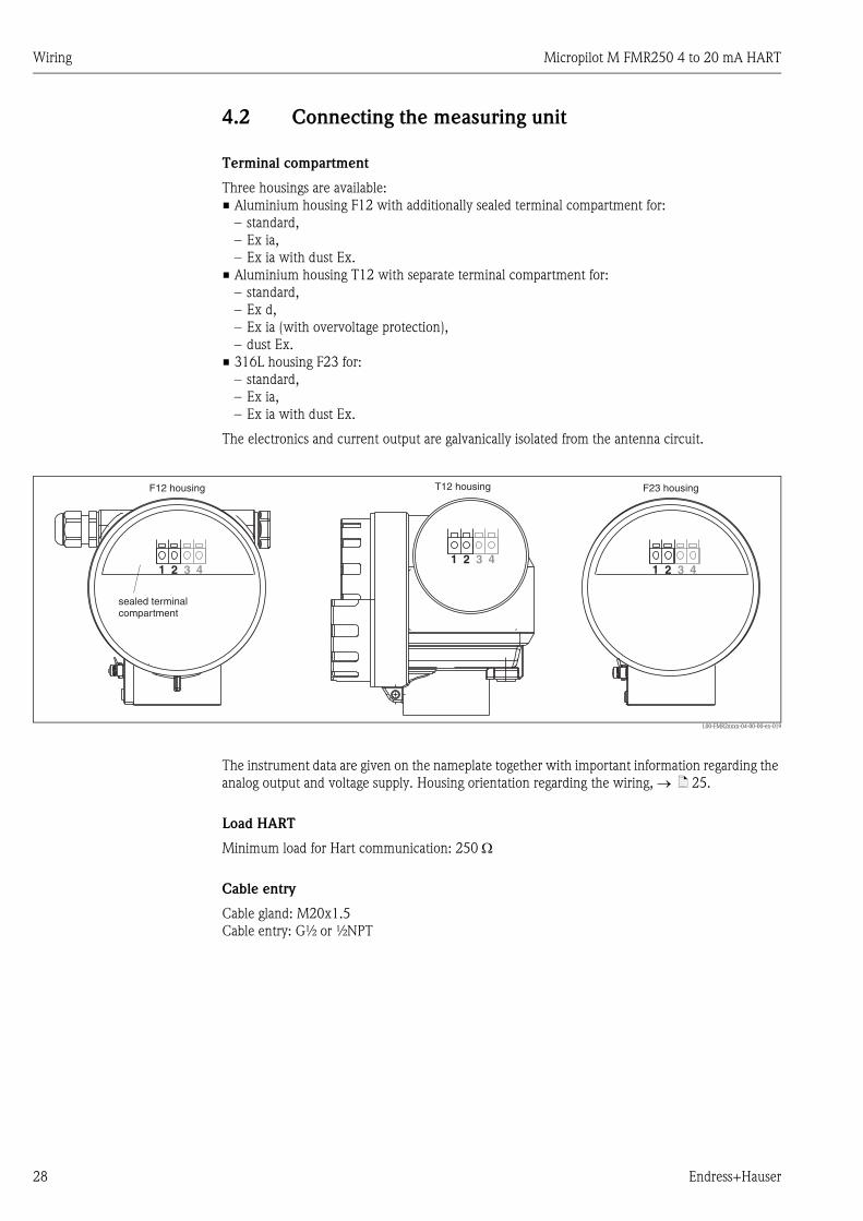
Terminal compartment
Three housings are available:
• Aluminium housing F12 with additionally sealed terminal compartment for:
– standard,
– Ex ia,
– Ex ia with dust Ex.
• Aluminium housing T12 with separate terminal compartment for:
– standard,
– Ex d,
– Ex ia (with overvoltage protection),
– dust Ex.
• 316L housing F23 for:
– standard,
– Ex ia,
– Ex ia with dust Ex.
The electronics and current output are galvanically isolated from the antenna circuit.
L00-FMR2xxxx-04-00-00-en-019
The instrument data are given on the nameplate together with important information regarding the
analog output and voltage supply. Housing orientation regarding the wiring, → ä 25.
Load HART
Minimum load for Hart communication: 250 Ω
Cable entry
Cable gland: M20x1.5
Cable entry: G½ or ½NPT
1 12 23 34 41 2 3 4
sealed terminalcompartment
F12 housing F23 housingT12 housing

Micropilot M FMR250 4 to 20 mA HART Wiring
Endress+Hauser 29
Supply voltage
The following values are the voltages across the terminals directly at the instrument:
Power consumption
min. 60 mW, max. 900 mW
Current consumption
• Device basic current:
3.6 to 22 mA, for HART Multidrop: start up current is 11 mA.
• Breakdown signal (NAMUR NE43):
adjustable
CommunicationCurrent
consumption
Terminal voltage
minimal maximal
HARTstandard
4 mA 16 V 36 V
20 mA 7.5 V 36 V
Ex ia4 mA 16 V 30 V
20 mA 7.5 V 30 V
Ex d4 mA 16 V 30 V
20 mA 11 V 30 V
dust Ex4 mA 16 V 30 V
20 mA 11 V 30 V
Fixed current, adjustable
e.g. for solar power
operation (measured
value transferred at
HART)
standard 11 mA 10 V1)
1) Short-term min. start-up voltage: 11.4 V
36 V
Ex ia 11 mA 10 V1) 30 V
Fixed current for HART
Multidrop mode
standard 4 mA2)
2) Start up current 11 mA.
16 V 36 V
Ex ia 4 mA2) 16 V 30 V

Wiring Micropilot M FMR250 4 to 20 mA HART
30 Endress+Hauser
4.2.1 HART connection with Endress+Hauser RMA422 / RN221N
L00-FMR2xxxx-04-00-00-xx-003
4.2.2 HART connection with other supplies
L00-FMR2xxxx-04-00-00-en-008
" Caution!
If the HART communication resistor is not built into the supply unit, it is necessary to insert a
communication resistor of 250 Ω into the 2-wire line.
4...20 mA
1 2 3 4
ENDRESS + HAUSERRMA 422
CommuboxFXA195
RMA422RN221N
Field Communicator375, 475
1# % &
Copy
G H I
P Q R S
, ( ) ‘
A B C
Paste
PageOn
PageUp
DeleteBksp
Insert
J K L
T U V
_ < >
D E F
Hot Key
+ Hot Key
M N O
W X Y Z
+ * /
4
7
.
2
5
8
0
375FIELD COMMUNICATOR
3
6
9
-
9 6
FMP40: LIC0001ONLINE
1 GROUP SELECT2 PV 8.7 m
HELP SAVE
dsdmdmdf das.asdas faasas la.
FieldCare
1 2 3 4
Field Communicator375, 475
1# % &
Copy
G H I
P Q R S
, ( ) ‘
A B C
Paste
PageOn
PageUp
DeleteBksp
Insert
J K L
T U V
_ < >
D E F
Hot Key
+ Hot Key
M N O
W X Y Z
+ * /
4
7
.
2
5
8
0
375FIELD COMMUNICATOR
3
6
9
-
9 6
FMP40: LIC0001ONLINE
1 GROUP SELECT2 PV 8.7 m
HELP SAVE
dsdmdmdf das.asdas faasas la. FieldCare
CommuboxFXA195
PLC
DC power supplyunit
or
4...20 mA
Micropilot M FMR250 4 to 20 mA HART Wiring
Endress+Hauser 31
4.3 Recommended connection
4.3.1 Equipotential bonding
Connect the equipotential bonding to the external ground terminal of the transmitter.
4.3.2 Wiring screened cable
" Caution!
In Ex applications, the screen must only be grounded on the sensor side. Further safety instructions
are given in the separate documentation for applications in explosion hazardous areas.
4.4 Degree of protection
• with closed housing: IP65, NEMA4X (higher degree of protection e.g. IP68 on request)
• with open housing: IP20, NEMA1 (also ingress protection of the display)
• antenna: IP68 (NEMA6P)
4.5 Post-connection check
After wiring the measuring instrument, perform the following checks:
• Is the terminal allocation correct (→ ä 26 and → ä 27)?
• Is the cable gland tight?
• Is the housing cover screwed tight?
• If auxiliary power is available:
Is the instrument ready for operation and does the liquid crystal display show any value?

Operation Micropilot M FMR250 4 to 20 mA HART
32 Endress+Hauser
5 Operation
5.1 Quick operation guide
L00-FMR250xx-19-00-00-en-002
ENDRESS + HAUSER
E+–
XX
X
X
X
SS
S
SS
S
O
O
O
OO
O
FF
F
F
F
>3 s
F
...
...
3x
���
���
�������
���� ��
�� ��������
�������� �
���� �
�������
�� ����� ��
�� ��������
���������
�������
�����
Example - Selection and configuration in Operation menu:
Group Selection
Function Groupunction
Note!
Selection menus:function
Typing in numerals and text:numeral / text
function
function
Group selection
Measured value display
1.) Change from Measured Value Display to by pressing
2.) Press or to select the required (e.g.. "basic setup (00)") and confirm by pressing
(e.g. "tank shape (002)") is selected.
The active selection is marked by a in front of the menu text.
3.) Activate Edit mode with or .
a) Select the required in selected (e.g. "tank shape (002)") with or .
b) confirms selection appears in front of the selected parameter
c) confirms the edited value system quits Edit mode
d) + (= ) interrupts selection system quits Edit mode
a) Press or to edit the first character of the (e.g. "empty calibr. (005)")
b) positions the cursor at the next character (a) until you have completed your input
c) if a symbol appears at the cursor, press to accept the value enteredsystem quits Edit mode
d) + (= ) interrupts the input,
4) Press to select the next (e.g. "medium property (003)")
5) Press + (= ) once return to previous (e.g. "tank shape (002)")
Press + (= ) twice return to
6) Press + (= ) to return to
F
S O
O
S O
F
S
X
S
F
S
F
F
O S X
O S
F
O X
F
O S X
O S
O X
�
�
�
�
�
�
�
First f
continue with
system quits Edit mode
�
Parameter
���������
���������������
!"���"����
"!#��$�"�����%"
����!��"!����
�!���"&!��
'�""���(�"���
)�*��������%
&���+���!���$�
$�!""
"������%�����
#�!��������%
"�&���
*�)��*��������$
*�)��*��������$
*�)�!��$��
��,��)"
"���)"
�������
*��!��"���
���������"���
���(� �����
)�*�
"��������
���'�$��� ���
�-���)�)��!�� ��
Micropilot M FMR250 4 to 20 mA HART Operation
Endress+Hauser 33
5.1.1 General structure of the operating menu
The operating menu is made up of two levels:
• Function groups (00, 01, 03, …, 0C, 0D): The individual operating options of the instrument
are split up roughly into different function groups. The function groups that are available include,
e.g.: "basic setup", "safety settings", "output", "display", etc.
• Functions (001, 002, 003, …, 0D8, 0D9): Each function group consists of one or more
functions. The functions perform the actual operation or parameterisation of the instrument.
Numerical values can be entered here and parameters can be selected and saved. The available
functions of the “basic setup” (00) function group include, e.g.: "tank shape" (002),
"medium property" (003), "process cond." (004), "empty calibr." (005), etc.
If, for example, the application of the instrument is to be changed, carry out the following
procedure:
1. Select the “basic setup” (00) function group.
2. Select the "tank shape" (002) function (where the existing tank shape is selected).
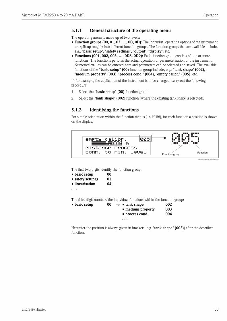
5.1.2 Identifying the functions
For simple orientation within the function menus (→ ä 86), for each function a position is shown
on the display.
L00-FMRxxxxx-07-00-00-en-005
The first two digits identify the function group:
The third digit numbers the individual functions within the function group:
Hereafter the position is always given in brackets (e.g. "tank shape" (002)) after the described
function.
• basic setup 00
• safety settings 01
• linearisation 04
. . .
• basic setup 00 → • tank shape 002
• medium property 003
• process cond. 004
. . .
Operation Micropilot M FMR250 4 to 20 mA HART
34 Endress+Hauser
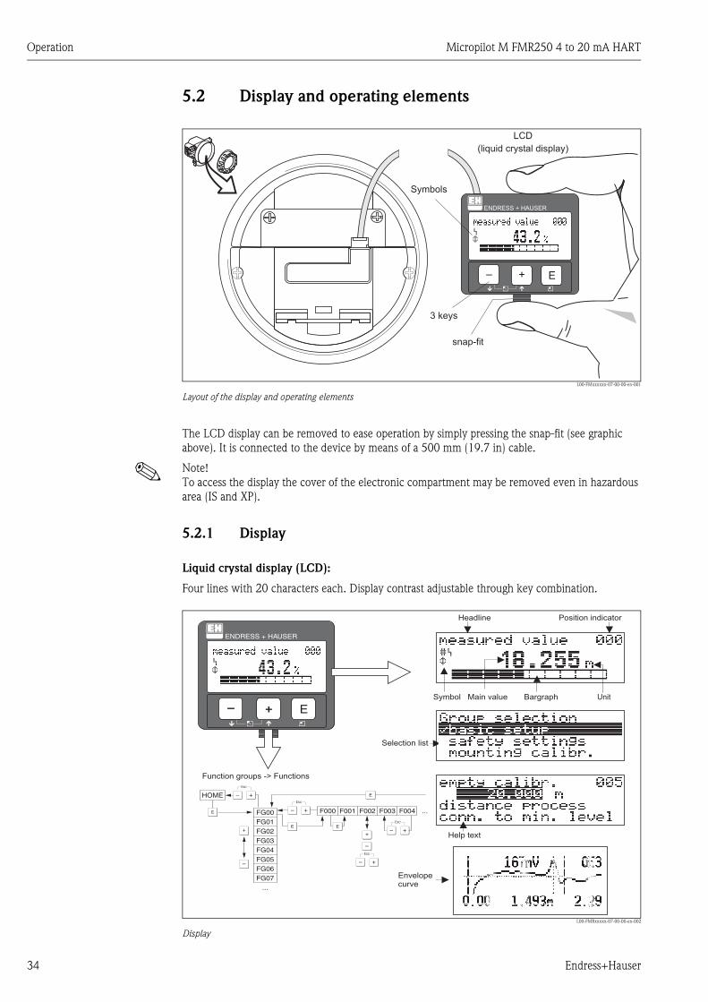
5.2 Display and operating elements
L00-FMxxxxxx-07-00-00-en-001
Layout of the display and operating elements
The LCD display can be removed to ease operation by simply pressing the snap-fit (see graphic
above). It is connected to the device by means of a 500 mm (19.7 in) cable.
! Note!
To access the display the cover of the electronic compartment may be removed even in hazardous
area (IS and XP).
5.2.1 Display
Liquid crystal display (LCD):
Four lines with 20 characters each. Display contrast adjustable through key combination.
L00-FMRxxxxx-07-00-00-en-002
Display
ENDRESS + HAUSER
E+–
ENDRESS+HAUSER
MICROPILOT II
ENDRESS+HAUSER
MICROPILOT II
IP 65IP 65
Order Code:Ser.-No.:
Order Code:Ser.-No.:
MessbereichMeasuring range
MessbereichMeasuring rangeU 16...36 V DC
4...20 mA
U 16...36 V DC
4...20 mA
max. 20 m
max. 20 m
Made
inG
erm
any
Maulb
urg
Made
inG
erm
any
Maulb
urg
T>70°C :
A
t >85°C
T>70°C :
A
t >85°C
LCD(liquid crystal display)
Symbols
3 keys
snap-fit
XX
X
XS
S
OO FF
F
F
HOME
FG00 F000 F001 F002 F003 F004 ...
FG01FG02FG03FG04FG05FG06FG07
...
ENDRESS + HAUSER
E+–
Headline Position indicator
Main value UnitSymbol
Selection list
Function groups -> Functions
Help text
Envelopecurve
Bargraph

Micropilot M FMR250 4 to 20 mA HART Operation
Endress+Hauser 35
5.2.2 Display symbols
The following table describes the symbols that appear on the liquid crystal display:
5.2.3 Key assignment
The operating elements are located inside the housing and are accessible for operation by opening
the lid of the housing.
Function of the keys
Sybmol Meaning
ALARM_SYMBOL
This alarm symbol appears when the instrument is in an alarm state. If the symbol flashes, this indicates a
warning.
LOCK_SYMBOL
This lock symbol appears when the instrument is locked, i.e. if no input is possible.
COM_SYMBOL
This communication symbol appears when a data transmission via e.g. HART, PROFIBUS PA or
FOUNDATION Fieldbus is in progress.
Key(s) Meaning
O or V Navigate upwards in the selection list.
Edit numeric value within a function.
S or W Navigate downwards in the selection list.
Edit numeric value within a function.
X or Z Navigate to the left within a function group.
F Navigate to the right within a function group, confirmation.
O and For
S and FContrast settings of the LCD.
O and S and F
Hardware lock / unlock
After a hardware lock, an operation of the instrument via display or
communication is not possible!
The hardware can only be unlocked via the display. An unlock parameter must
be entered to do so.

Operation Micropilot M FMR250 4 to 20 mA HART
36 Endress+Hauser
5.3 Local operation
5.3.1 Locking of the configuration mode
The Micropilot can be protected in two ways against unauthorised changing of instrument data,
numerical values or factory settings:
Function "unlock parameter" (0A4):
A value <> 100 (e.g. 99) must be entered in "unlock parameter" (0A4) in the
"diagnostics" (0A) function group. The lock is shown on the display by the symbol and can be
released again either via the display or by communication.
Hardware lock:
The instrument is locked by pressing the O, S and F keys at the same time.
The lock is shown on the display by the symbol and can only be unlocked again
via the display by pressing the O, S and F keys at the same time again. It is not possible to unlock
the hardware by communication. All parameters can de displayed even if the instrument is locked.
⇒ O, S and F press simultaneous
⇓
⇓The LOCK_SYMBOL appears on the LCD.
ENDRESS + HAUSER
E+–
Micropilot M FMR250 4 to 20 mA HART Operation
Endress+Hauser 37
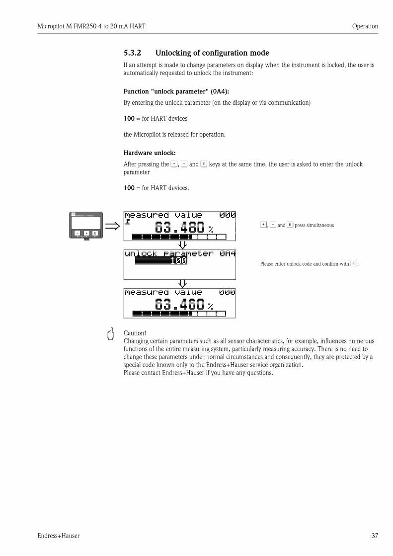
5.3.2 Unlocking of configuration mode
If an attempt is made to change parameters on display when the instrument is locked, the user is
automatically requested to unlock the instrument:
Function "unlock parameter" (0A4):
By entering the unlock parameter (on the display or via communication)
100 = for HART devices
the Micropilot is released for operation.
Hardware unlock:
After pressing the O, S and F keys at the same time, the user is asked to enter the unlock
parameter
100 = for HART devices.
" Caution!
Changing certain parameters such as all sensor characteristics, for example, influences numerous
functions of the entire measuring system, particularly measuring accuracy. There is no need to
change these parameters under normal circumstances and consequently, they are protected by a
special code known only to the Endress+Hauser service organization.
Please contact Endress+Hauser if you have any questions.
⇒ O, S and F press simultaneous
⇓Please enter unlock code and confirm with F.
⇓
ENDRESS + HAUSER
E+–
Operation Micropilot M FMR250 4 to 20 mA HART
38 Endress+Hauser
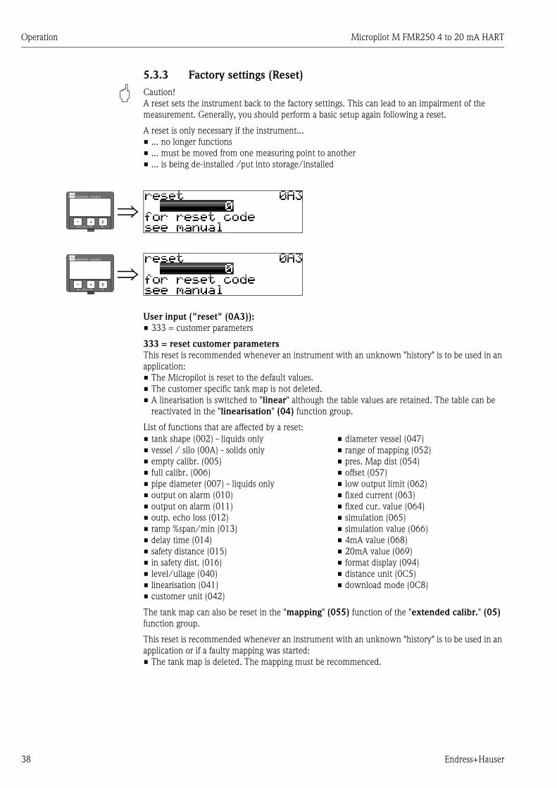
5.3.3 Factory settings (Reset)
" Caution!
A reset sets the instrument back to the factory settings. This can lead to an impairment of the
measurement. Generally, you should perform a basic setup again following a reset.
A reset is only necessary if the instrument...
• ... no longer functions
• ... must be moved from one measuring point to another
• ... is being de-installed /put into storage/installed
User input ("reset" (0A3)):
• 333 = customer parameters
333 = reset customer parameters
This reset is recommended whenever an instrument with an unknown "history" is to be used in an
application:
• The Micropilot is reset to the default values.
• The customer specific tank map is not deleted.
• A linearisation is switched to "linear" although the table values are retained. The table can be
reactivated in the "linearisation" (04) function group.
List of functions that are affected by a reset:
The tank map can also be reset in the "mapping" (055) function of the "extended calibr." (05)
function group.
This reset is recommended whenever an instrument with an unknown "history" is to be used in an
application or if a faulty mapping was started:
• The tank map is deleted. The mapping must be recommenced.
⇒ENDRESS + HAUSER
E+–
⇒ENDRESS + HAUSER
E+–
• tank shape (002) - liquids only
• vessel / silo (00A) - solids only
• empty calibr. (005)
• full calibr. (006)
• pipe diameter (007) - liquids only
• output on alarm (010)
• output on alarm (011)
• outp. echo loss (012)
• ramp %span/min (013)
• delay time (014)
• safety distance (015)
• in safety dist. (016)
• level/ullage (040)
• linearisation (041)
• customer unit (042)
• diameter vessel (047)
• range of mapping (052)
• pres. Map dist (054)
• offset (057)
• low output limit (062)
• fixed current (063)
• fixed cur. value (064)
• simulation (065)
• simulation value (066)
• 4mA value (068)
• 20mA value (069)
• format display (094)
• distance unit (0C5)
• download mode (0C8)

Micropilot M FMR250 4 to 20 mA HART Operation
Endress+Hauser 39
5.4 Display and acknowledging error messages
Type of error
Errors that occur during commissioning or measuring are displayed immediately on the local
display. If two or more system or process errors occur, the error with the highest priority is the one
shown on the display.
The measuring system distinguishes between two types of error:
• A (Alarm):
Instrument goes into a defined state (e.g. max 22 mA)
Indicated by a constant symbol.
(For a description of the codes, → ä 68)
• W (Warning):
Instrument continue measuring, error message is displayed.
Indicated by a flashing symbol.
(For a description of the codes, → ä 68)
• E (Alarm / Warning):
Configurable (e.g. loss of echo, level within the safety distance)
Indicated by a constant/flashing symbol.
(For a description of the codes, → ä 68)
5.4.1 Error messages
Error messages appear as four lines of plain text on the display. In addition, a unique error code is
also output. A description of the error codes, → ä 68.
• The "diagnostics" (0A) function group can display current errors as well as the last errors that
occurred.
• If several current errors occur, use O or S to page through the error messages.
• The last occurring error can be deleted in the "diagnostics" (0A) function group
with the funktion"clear last error" (0A2).
⇒ENDRESS + HAUSER
E+–

Operation Micropilot M FMR250 4 to 20 mA HART
40 Endress+Hauser
5.5 HART communication
Apart from local operation, you can also parameterise the measuring instrument and view measured
values by means of a HART protocol. There are two options available for operation:
• Operation via the universal Field Communicator 375, 475.
• Operation via the Personal Computer (PC) using the operating program (e.g. FieldCare, → ä 30).
! Note!
The Micropilot M can also be operated locally using the keys. If operation is prevented by the keys
being locked locally, parameter entry via communication is not possible either.
5.5.1 Field Communicator 375, 475
All device functions can be adjusted via menu operation with the Field Communicator 375, 475.
L00-FMR2xxxx-07-00-00-yy-007
Menu operation with the Field Communicator 375
! Note!
• Further information on the Field Communicator 375, 475 is given in the respective operating
manual included in the transport bag of the instrument.
1# % &
Copy
G H I
P Q R S
, ( ) ‘
A B C
Paste
PageOn
PageUp
DeleteBksp
Insert
J K L
T U V
_ < >
D E F
Hot Key
+ Hot Key
M N O
W X Y Z
+ * /
4
7
.
2
5
8
0
375FIELD COMMUNICATOR
3
6
9
-
9 6
FMR231: LIC0001ONLINE
1 GROUP SELECT2 PV 8.7 m
HELP SAVE
dsdmdmdf das.asdas faasas la.
PageOn
PageUp
Bksp
Delete
Delete
FMR231: LIC0001ONLINE
1 GROUP SELECTION2 PV 8.7 m
HELP SAVE
dsdmdmdf das.asdas faasas la.
FMR231: LIC0001GROUP SELECTION
HOMESAVE
dsdmdmdf das.asdas faasas la.H
FMR231: LIC0001
HOMESAVE
dsdmdmdf das.asdas faasas la.H
Bksp
1 BASIC SETUP2 SAFETY SETTINGS
BASIC SETUP
1 MEASURED VALUE
4 PROCESS COND.
5 EMPTY CALIBR.
3 MEDIUM PROPERTY
4 EXTENDED CALIB.
5 OUTPUT
3 LINEARISATION
2 TANK SHAPE

Micropilot M FMR250 4 to 20 mA HART Operation
Endress+Hauser 41
5.5.2 Endress+Hauser operating program
FieldCare is an Endress+Hauser asset management tool based on FDT technology. With FieldCare,
you can configure all Endress+Hauser devices as well as devices from other manufacturers that
support the FDT standard. Hardware and software requirements you can find on the internet:
www.endress.com È select your country È Search: FieldCare È FieldCare È Technical Data.
FieldCare supports the following functions:
• Configuration of transmitters in online operation
• Singal analysis via envelope curve
• Tank linearisation
• Loading and saving device data (upload/download)
• Documentation of the measuring point
Connection options:
• HART via Commubox FXA195 and the USB port on a computer
• Commubox FXA291 with ToF Adapter FXA291 (USB) via service interface
Menu-guided commissioning
MicropilotM-en-415

Operation Micropilot M FMR250 4 to 20 mA HART
42 Endress+Hauser
Signal analysis via envelope curve
MicropilotM-en-306
Tank linearisation
MicropilotM-en-307

Micropilot M FMR250 4 to 20 mA HART Commissioning
Endress+Hauser 43
6 Commissioning
6.1 Function check
Make sure that all final checks have been completed before you start up your measuring point:
• Checklist "Post installation check", → ä 25.
• Checklist "Post connection check", → ä 31.
6.2 Switching on the measuring device
When the instrument is switched on for the first time, the following messages appear in a sequence
of 5 s on the display: software version, communication protocol and language selection.
⇒ Select the language (this message appears the first time
the instrument is switched on)
⇓Select the basic unit (this message appears the first time
the instrument is switched on)
⇓The current measured value is displayed
⇓ After F is pressed, you reach the group selection
This selection enables you to perform the basic setup
ENDRESS + HAUSER
E+–

Commissioning Micropilot M FMR250 4 to 20 mA HART
44 Endress+Hauser
6.3 Basic Setup
L00-FMR250xx-19-00-00-en-001
SD
SD
F
F
L
L
D
D
E
E
flange:reference pointofmeasurement
flange:reference pointofmeasurement
�!���"&!��
)�*��������%
'�""���(�"���
*��!��"���
*�)�!��$�� *�)�!��$��
��,��) "���)
*�!"����%����)�
.������
*�!"����%����)�
.������
*�!"����%����)�
��!�)!�)
*�!"����%����)�
��!�)!�)
�����)�!*����
*!����%
*!����%
"!#��$�"�����%"
����!��"!����
�-���)�)��!�� ��
���
�*��$��!�� �� �*��$��!�� ��
#�����!�� �� #�����!�� ��
(for bypass/stilling well)
(de
scrip
tio
n s
ee
BA
29
1F
/00
/EN
)
E = empty calibr. (= zero), setting in 005
F = full calibr. (= span), setting in 006
D = distance (distance flange / product), display in 0A5
L = level, display in 0A6
SD = safety distance, setting in 015
ba
sic
se
tup
(sta
nd
ard
- liq
uid
s)
ba
sic
se
tup
(sta
nd
ard
- s
olid
s)
option
level measurement in liquids
level measurement in solids

Micropilot M FMR250 4 to 20 mA HART Commissioning
Endress+Hauser 45
" Caution!
The basic setup is sufficient for successful commissioning in most applications. Complex measuring
operations necessitate additional functions that the user can use to customise the Micropilot as
necessary to suit his specific requirements. The functions available to do this are described in detail
in the BA291F/00/EN.
Comply with the following instructions when configuring the functions in the "basic setup" (00):
• Select the functions as described → ä 32.
• Some functions can only be used depending on the parameterisation of the instrument. For
example, the pipe diameter of a stilling well can only be entered if "stilling well" was selected
beforehand in the "tank shape" (002) function.
• Certain functions (e.g. starting an interference echo mapping (053)) prompt you to confirm your
data entries. Press O or S to select "YES" and press F to confirm. The function is now started.
• If you do not press a key during a configurable time period (→ function group "display" (09)),
an automatic return is made to the home position (measured value display).
! Note!
• The instrument continues to measure while data entry is in progress, i.e. the current measured
values are output via the signal outputs in the normal way.
• If the envelope curve mode is active on the display, the measured values are updated in a slower
cycle time. Thus, it is advisable to leave the envelope curve mode after the measuring point has
been optimised.
• If the power supply fails, all preset and parameterised values remain safely stored in the EEPROM.
• All functions are described in detail, as is the overview of the operating menu itself, in the manual
"BA291F - Description of Instrument Functions", which is found on the enclosed CD-ROM.
• The default values of the parameters are typed in boldface.

Commissioning Micropilot M FMR250 4 to 20 mA HART
46 Endress+Hauser
6.4 Basic Setup with the device display
Function "measured value" (000)
This function displays the current measured value in the selected unit
(see "customer unit" (042) function). The number of digits after decimal point can be selected in
the "no.of decimals" (095) function.
6.4.1 Function group "basic setup" (00)
Function "media type" (001)
This function is used to select the media type.
Selection:
• liquid
• solid
⇒ENDRESS + HAUSER
E+–
⇒ENDRESS + HAUSER
E+–
⇒ENDRESS + HAUSER
E+–
With the selection "liquid" only the
following functions can be adjusted:
With the selection "solids" only the
following functions can be adjusted:
• tank shape 002 • vessel / silo 00A
• medium property 003 • medium property 00B
• process cond. 004 • process cond. 00C
• empty calibr. 005 • empty calibr. 005
• full calibr. 006 • full calibr. 006
• pipe diameter 007 • check distance 051
• check distance 051 • range of mapping 052
• range of mapping 052 • start mapping 053
• start mapping 053 • . . .
• . . .

Micropilot M FMR250 4 to 20 mA HART Commissioning
Endress+Hauser 47
Function "tank shape" (002), liquids only
This function is used to select the tank shape.
Selection:
• dome ceiling
• horizontal cyl
• bypass
• stilling well
• flat ceiling
• sphere
L00-FMR2xxxx-14-00-06-en-007
Function "medium property" (003), liquids only
This function is used to select the dielectric constant.
Selection:
• unknown
• DC: < 1.9
• DC: 1.9 ... 4
• DC: 4 ... 10
• DC: > 10
⇒ENDRESS + HAUSER
E+–
dome ceiling
flat ceiling sphere
horizontal cyl
bypass stilling well
⇒ENDRESS + HAUSER
E+–
Product class DC (εr) Examples
A 1.4 to 1.9 non-conducting liquids, e.g. liquefied gas 1)
1) Treat Ammonia NH3 as a medium of group A, i.e. use FMR230 in a stilling well.
B 1.9 to 4 non-conducting liquids, e.g. benzene, oil, toluene, …
C 4 to 10 e.g. concentrated acids, organic solvents, esters, aniline, alcohol, acetone, …
D >10 conducting liquids, e.g. aqueous solutions, dilute acids and alkalis
Commissioning Micropilot M FMR250 4 to 20 mA HART
48 Endress+Hauser
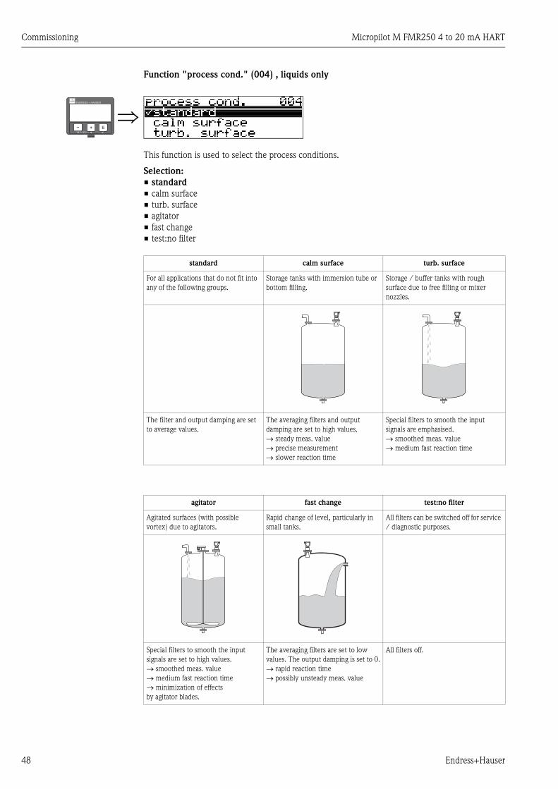
Function "process cond." (004) , liquids only
This function is used to select the process conditions.
Selection:
• standard
• calm surface
• turb. surface
• agitator
• fast change
• test:no filter
⇒ENDRESS + HAUSER
E+–
standard calm surface turb. surface
For all applications that do not fit into
any of the following groups.
Storage tanks with immersion tube or
bottom filling.
Storage / buffer tanks with rough
surface due to free filling or mixer
nozzles.
The filter and output damping are set
to average values.
The averaging filters and output
damping are set to high values.
→ steady meas. value
→ precise measurement
→ slower reaction time
Special filters to smooth the input
signals are emphasised.
→ smoothed meas. value
→ medium fast reaction time
agitator fast change test:no filter
Agitated surfaces (with possible
vortex) due to agitators.
Rapid change of level, particularly in
small tanks.
All filters can be switched off for service
/ diagnostic purposes.
Special filters to smooth the input
signals are set to high values.
→ smoothed meas. value
→ medium fast reaction time
→ minimization of effects
by agitator blades.
The averaging filters are set to low
values. The output damping is set to 0.
→ rapid reaction time
→ possibly unsteady meas. value
All filters off.

Micropilot M FMR250 4 to 20 mA HART Commissioning
Endress+Hauser 49
Function "vessel / silo" (00A), solids only
This function is used to select the vessel / silo.
Selection:
• unknown
• metal silo
• concrete silo
• bin / bunker
• dome
• stockpile
• conveyor belt
Function "medium property" (00B), solids only
This function is used to select the dielectric constant.
Selection:
• unknown
• DC: 1.6 ... 1.9
• DC: 1.9 ... 2.5
• DC: 2.5 ... 4
• DC: 4 ... 7
• DC: > 7
The respective lower group applies for very loose or loosened bulk solids.
⇒ENDRESS + HAUSER
E+–
⇒ENDRESS + HAUSER
E+–
Media group DC (εr) Examples
A 1.6 to 1.9
– Plastic granulate
– White lime, special cement
– Sugar
B 1.9 to 2.5 – Portland cement, plaster
C 2.5 to 4
– Grain, seeds
– Ground stones
– Sand
D 4 to 7– Naturally moist (ground) stones, ores
– Salt
E > 7
– Metallic powder
– Carbon black
– Coal
Commissioning Micropilot M FMR250 4 to 20 mA HART
50 Endress+Hauser
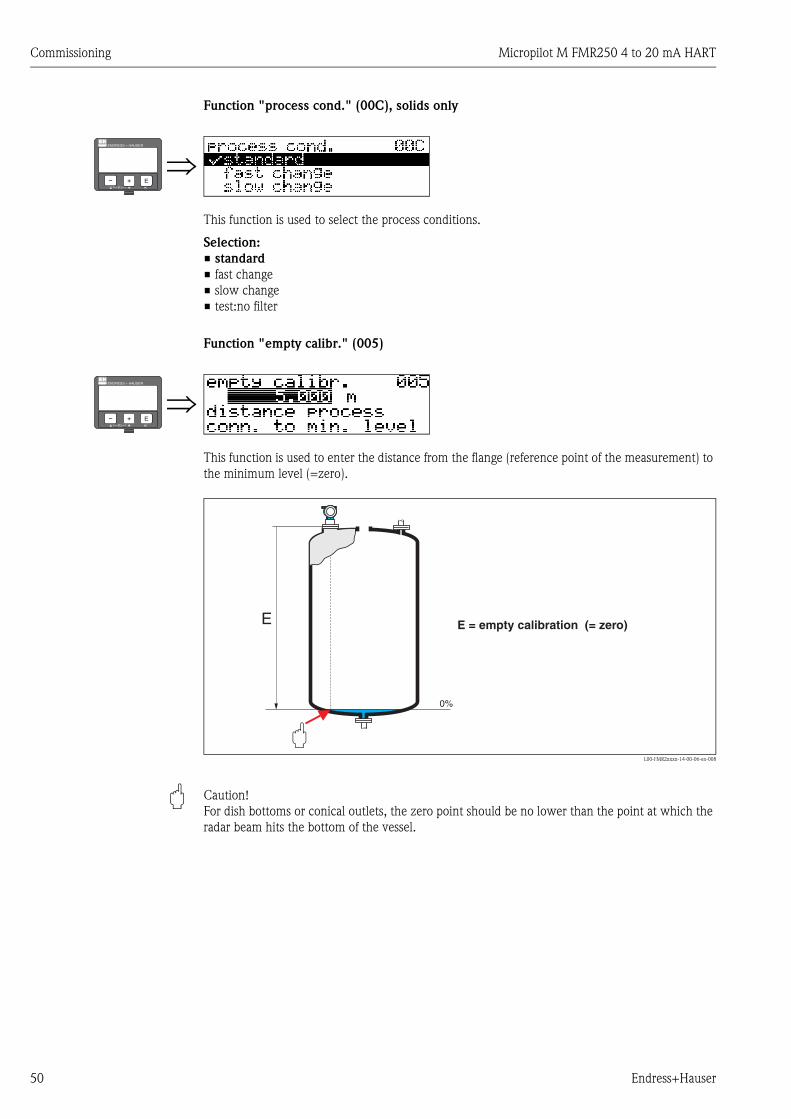
Function "process cond." (00C), solids only
This function is used to select the process conditions.
Selection:
• standard
• fast change
• slow change
• test:no filter
Function "empty calibr." (005)
This function is used to enter the distance from the flange (reference point of the measurement) to
the minimum level (=zero).
L00-FMR2xxxx-14-00-06-en-008
" Caution!
For dish bottoms or conical outlets, the zero point should be no lower than the point at which the
radar beam hits the bottom of the vessel.
⇒ENDRESS + HAUSER
E+–
⇒ENDRESS + HAUSER
E+–

Micropilot M FMR250 4 to 20 mA HART Commissioning
Endress+Hauser 51
Function "full calibr." (006)
This function is used to enter the distance from the minimum level to the maximum level (=span).
In principle, it is possible to measure up to the tip of the antenna. However, due to considerations
regarding corrosion and build-up, the end of the measuring range should not be chosen any closer
than 50 mm (1.97 in) to the tip of the antenna.
L00-FMR2xxxx-14-00-06-en-009
! Note!
If bypass or stilling well was selected in the "tank shape" (002) function, the pipe diameter is
requested in the following step.
Function "pipe diameter" (007)
This function is used to enter the pipe diameter of the stilling well or bypass pipe.
L00-FMR2xxxx-14-00-00-en-011
Microwaves propagate more slowly in pipes than in free space. This effect depends on the inside
diameter of the pipe and is automatically taken into account by the Micropilot. It is only necessary
to enter the pipe diameter for applications in a bypass or stilling well.
⇒ENDRESS + HAUSER
E+–
⇒ENDRESS + HAUSER
E+–
100%
0%
ø
100%
0%
ø
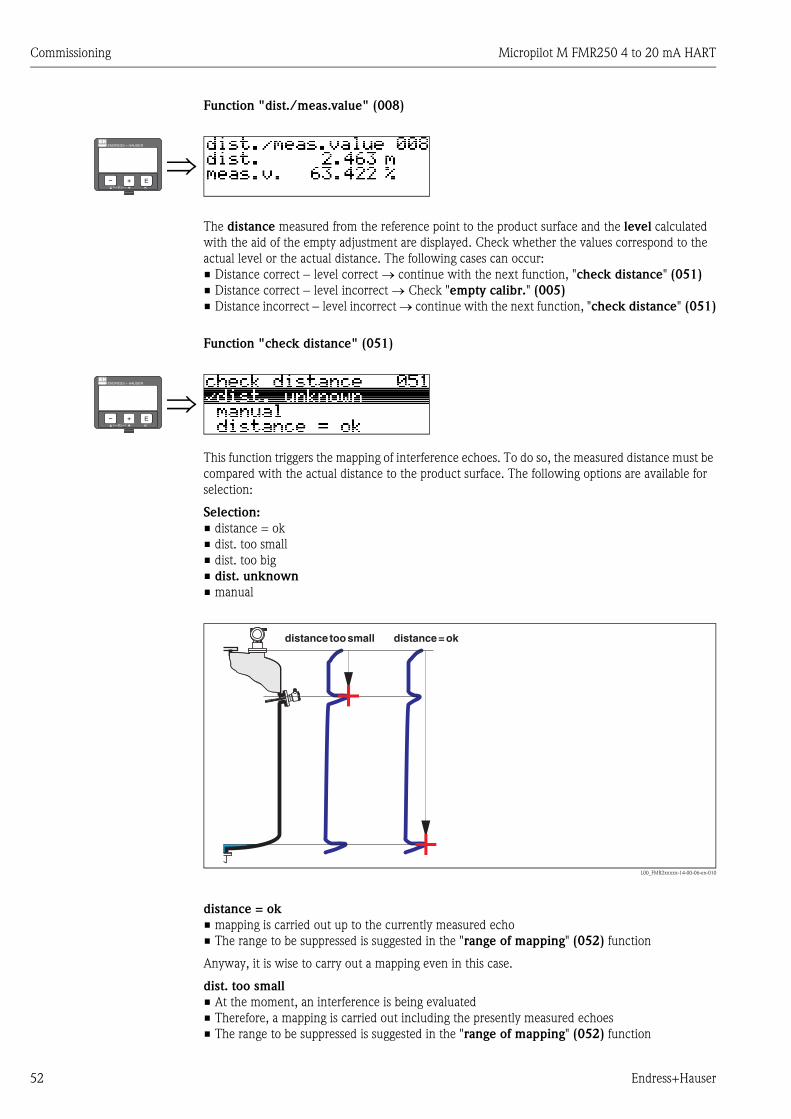
Commissioning Micropilot M FMR250 4 to 20 mA HART
52 Endress+Hauser
Function "dist./meas.value" (008)
The distance measured from the reference point to the product surface and the level calculated
with the aid of the empty adjustment are displayed. Check whether the values correspond to the
actual level or the actual distance. The following cases can occur:
• Distance correct − level correct → continue with the next function, "check distance" (051)
• Distance correct − level incorrect → Check "empty calibr." (005)
• Distance incorrect − level incorrect → continue with the next function, "check distance" (051)
Function "check distance" (051)
This function triggers the mapping of interference echoes. To do so, the measured distance must be
compared with the actual distance to the product surface. The following options are available for
selection:
Selection:
• distance = ok
• dist. too small
• dist. too big
• dist. unknown
• manual
L00_FMR2xxxxx-14-00-06-en-010
distance = ok
• mapping is carried out up to the currently measured echo
• The range to be suppressed is suggested in the "range of mapping" (052) function
Anyway, it is wise to carry out a mapping even in this case.
dist. too small
• At the moment, an interference is being evaluated
• Therefore, a mapping is carried out including the presently measured echoes
• The range to be suppressed is suggested in the "range of mapping" (052) function
⇒ENDRESS + HAUSER
E+–
⇒ENDRESS + HAUSER
E+–

Micropilot M FMR250 4 to 20 mA HART Commissioning
Endress+Hauser 53
dist. too big
• This error cannot be remedied by interference echo mapping
• Check the application parameters (002), (003), (004) and "empty calibr." (005)
dist. unknown
If the actual distance is not known, no mapping can be carried out.
manual
A mapping is also possible by manual entry of the range to be suppressed. This entry is made in the
"range of mapping" (052) function.
" Caution!
The range of mapping must end 0,5 m (1.6 ft) before the echo of the actual level. For an empty
vessel, do not enter E, but E – 0,5 m (1.6 ft)). If a mapping already exists, it is overwriten up to the
distance specified in "range of mapping" (052). Beyond this value the existing mapping remains
unchanged.
Function "range of mapping" (052)
This function displays the suggested range of mapping. The reference point is always the reference
point of the measurement (→ ä 44). This value can be edited by the operator.
For manual mapping, the default value is 0 m.
Function "start mapping" (053)
This function is used to start the interference echo mapping up to the distance given in "range of
mapping" (052).
Selection:
• off → no mapping is carried out
• on → mapping is started
During the mapping process the message "record mapping" is displayed.
" Caution!
A mapping will be recorded only, if the device is not in alarm-state.
⇒ENDRESS + HAUSER
E+–
⇒ENDRESS + HAUSER
E+–

Commissioning Micropilot M FMR250 4 to 20 mA HART
54 Endress+Hauser
Function "dist./meas.value" (008)
The distance measured from the reference point to the product surface and the level calculated
with the aid of the empty adjustment are displayed. Check whether the values correspond to the
actual level or the actual distance. The following cases can occur:
• Distance correct − level correct → continue with the next function, "check distance" (051)
• Distance correct − level incorrect → Check "empty calibr." (005)
• Distance incorrect − level incorrect → continue with the next function, "check distance" (051)
⇒ENDRESS + HAUSER
E+–
⇒⇓ After 3 s, the following message appears
ENDRESS + HAUSER
E+–

Micropilot M FMR250 4 to 20 mA HART Commissioning
Endress+Hauser 55
6.4.2 Envelope curve with device display
After the basic setup, an evaluation of the measurement with the aid of the envelope curve
("envelope curve" (0E) function group) is recommended.
Function "plot settings" (0E1)
Select which information will be displayed in the LCD:
• envelope curve
• env.curve+FAC (on FAC see BA291F/00/EN)
• env.curve+cust.map (i.e. customer tank map is also displayed)
Function "recording curve" (0E2)
This function defines whether the envelope curve is read as a
• single curve
or
• cyclic.
! Note!
• If the cyclical envelope curve is active in the display, the measured value is refreshed in a slower
cycle time. It is therefore recommended to exit the envelope curve display after optimising the
measuring point.
• An orientation of the Micropilot can help to optimise measurement in applications with very
weak level echos or strong interference echos by increasing the useful echo/reducing the
interference echo (see "Orientation of the Micropilot", → ä 74).
When using the Wave Guide antenna: No orientation is required!
⇒ENDRESS + HAUSER
E+–
⇒ENDRESS + HAUSER
E+–

Commissioning Micropilot M FMR250 4 to 20 mA HART
56 Endress+Hauser
Function "envelope curve display" (0E3)
The envelope curve is displayed in this function. You can use it to obtain the following information:
L00-FMU4xxxx-07-00-00-en-003
Navigating in the envelope curve display
Using navigation, the envelope curve can be scaled horizontally and vertically and shifted to the left
or the right. The active navigation mode is indicated by a symbol in the top left hand corner of the
display.
L00-FMxxxxxx-07-00-00-en-004
Horizontal Zoom mode
Firstly, go into the envelope curve display. Then press O or S to switch to the envelope curve
navigation. You are then in Horizontal Zoom mode. Either or is displayed.
• O increases the horizontal scale.
• S reduces the horizontal scale.
L00-FMxxxxxx-07-00-00-yy-007
minimum distanceof the plot
maximum distanceof the plot
distance ofevaluated echo
interference echo
evaluated echois marked
quality ofevaluated echo
empty calibr.envelope curveonly
envelope curve andinterference echosuppression (map)
level echomap
full calibr.
…
/01
Move mode:
- m
-
oved to the left
moved to the right
Horizontal Zoom mode:
- h
-
orizontal zoom in
horizontal zoom out
Vertical Zoom mode:
- vertical zoom (4 steps)
OS

Micropilot M FMR250 4 to 20 mA HART Commissioning
Endress+Hauser 57
Move mode
Then press F to switch to Move mode. Either or is displayed.
• O shifts the curve to the right.
• S shifts the curve to the left.
L00-FMxxxxxx-07-00-00-yy-008
Vertical Zoom mode
Press F once more to switch to Vertical Zoom mode. is displayed. You now have the following
options.
• O increases the vertical scale.
• S reduces the vertical scale.
The display icon shows the current zoom factor ( to ).
L00-FMxxxxxx-07-00-00-yy-009
Exiting the navigation
• Press F again to run through the different modes of the envelope curve navigation.
• Press O and S to exit the navigation. The set increases and shifts are retained. Only when you
reactivate the "recording curve" (0E2) function does the Micropilot use the standard display
again.
OS
OS
⇒⇓ After 3 s, the following message appears
ENDRESS + HAUSER
E+–
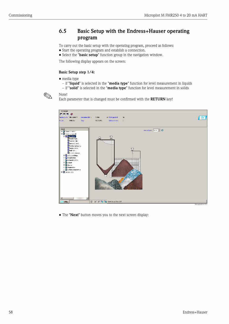
Commissioning Micropilot M FMR250 4 to 20 mA HART
58 Endress+Hauser
6.5 Basic Setup with the Endress+Hauser operating
program
To carry out the basic setup with the operating program, proceed as follows:
• Start the operating program and establish a connection.
• Select the "basic setup" function group in the navigation window.
The following display appears on the screen:
Basic Setup step 1/4:
• media type
– if "liquid" is selected in the "media type" function for level measurement in liquids
– if "solid" is selected in the "media type" function for level measurement in solids
! Note!
Each parameter that is changed must be confirmed with the RETURN key!
MicropilotM-en-411
• The "Next" button moves you to the next screen display:
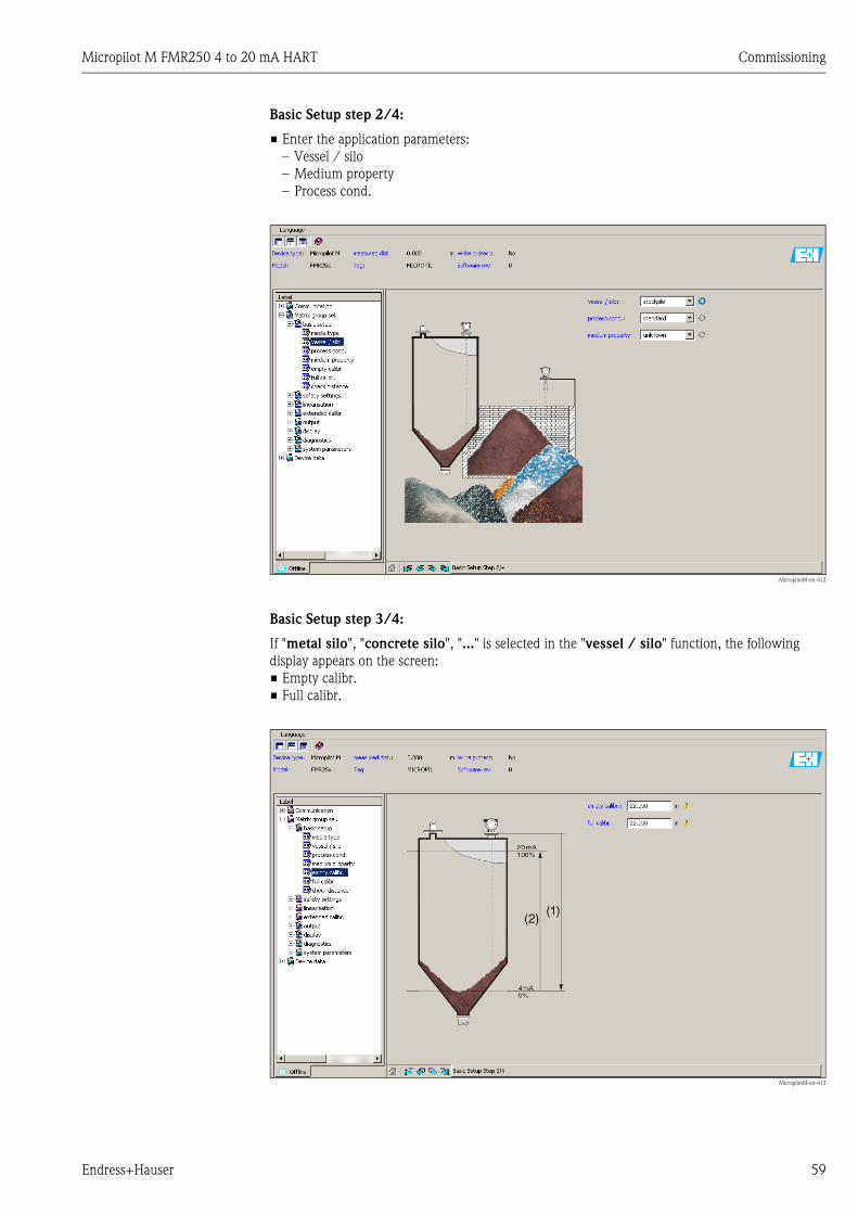
Micropilot M FMR250 4 to 20 mA HART Commissioning
Endress+Hauser 59
Basic Setup step 2/4:
• Enter the application parameters:
– Vessel / silo
– Medium property
– Process cond.
MicropilotM-en-412
Basic Setup step 3/4:
If "metal silo", "concrete silo", "..." is selected in the "vessel / silo" function, the following
display appears on the screen:
• Empty calibr.
• Full calibr.
MicropilotM-en-413

Commissioning Micropilot M FMR250 4 to 20 mA HART
60 Endress+Hauser
Basic Setup step 4/4:
• This step starts the tank mapping
• The measured distance and the current measured value are always displayed in the header
MicropilotM-en-404
6.5.1 Signal analysis via envelope curve
After the basic setup, an evaluation of the measurement using the envelope curve is recommended.
MicropilotM-en-306
! Note!
If the level of echo is very weak or there is a heavy interference echo, an orientation of the
Micropilot can help optimise the measurement (increase of the useful echo/reduction of the
interference echo).

Micropilot M FMR250 4 to 20 mA HART Commissioning
Endress+Hauser 61
6.5.2 User-specific applications (operation)
For details of setting the parameters of user-specific applications, see separate documentation
BA291F/00/EN "Description of Instrument Functions" on the enclosed CD-ROM.
Maintenance Micropilot M FMR250 4 to 20 mA HART
62 Endress+Hauser
7 Maintenance
The Micropilot M measuring instrument requires no special maintenance.
Exterior cleaning
When cleaning the exterior of measuring devices, always use cleaning agents that do not attack the
surface of the housing and the seals.
Replacing seals
The process seals of the sensors must be replaced periodically, particularly if molded seals (aseptic
construction) are used. The period between changes depends on the frequency of cleaning cycles
and on the temperature of the measured substance and the cleaning temperature.
Repairs
The Endress+Hauser repair concept assumes that the measuring devices have a modular design and
that customers are able to undertake repairs themselves (→ ä 76, "Spare Parts"). Please contact
Endress+Hauser Service for further information on service and spare parts.
Repairs to Ex-approved devices
When carrying out repairs to Ex-approved devices, please note the following:
• Repairs to Ex-approved devices may only be carried out by trained personnel or by the
Endress+Hauser Service.
• Comply with the prevailing standards, national Ex-area regulations, safety instructions (XA) and
certificates.
• Only use original spare parts from Endress+Hauser.
• When ordering a spare part, please note the device designation on the nameplate. Only replace
parts with identical parts.
• Carry out repairs according to the instructions. On completion of repairs, carry our the specified
routine test on the device.
• Only Endress+Hauser Service may convert a certified device into a different certified variant.
• Document all repair work and conversions.
Replacement
After a complete Micropilot or electronic module has been replaced, the parameters can be
downloaded into the instrument again via the communication interface. Prerequisite to this is that
the data were uploaded to the PC beforehand using the FieldCare.
Measurement can continue without having to carry out a new setup.
• You may have to activate linearisation (see BA291F/00/EN on the enclosed CD-ROM)
• You may need to record the tank map again (see Basic Setup)
After an antenna component or electronic has been replaced, a new calibration must be carried out.
This is described in the repair instructions.

Micropilot M FMR250 4 to 20 mA HART Accessories
Endress+Hauser 63
8 Accessories
Various accessories, which can be ordered separately from Endress+Hauser, are available for the
Micropilot M.
8.1 Weather protection cover
A Weather protection cover made of stainless steel is recommended for outdoor mounting (order
code: 543199-0001). The shipment includes the protective cover and tension clamp.
L00-FMR2xxxx-00-00-06-en-001
8.2 Commubox FXA195 HART
For intrinsically safe communication with FieldCare via the USB interface.
For details refer to TI404F/00/EN.
8.3 Commubox FXA291
The Commubox FXA291 connects Endress+Hauser field instruments with CDI interface
(= Endress+Hauser Common Data Interface) to the USB interface of a personal computer or a
notebook. For details refer to TI405C/07/EN.
! Note!
For the instrument you need the "ToF Adapter FXA291" as an additional accessory.
8.4 ToF Adapter FXA291
The ToF Adapter FXA291 connects the Commubox FXA291 via the USB interface of a personal
computer or a notebook to the instrument. For details refer to KA271F/00/A2.
ENDRESS+HAUSER
MICROPILOT II
ENDRESS+HAUSER
MICROPILOT II
IP 65
Order Code:Ser.-No.:
Order Code:Ser.-No.:
MessbereichMeasuring range
MessbereichMeasuring rangeU 16...36 V DC
4...20 mA
U 16...36 V DC4...20 mA
max. 20 m
max. 20 m
Ma
de
in G
erm
any
Ma
ulb
urg
Ma
de
in G
erm
any
Ma
ulb
urg
T>70°C :
A
t >85°C
T>70°C :
A
t >85°C
70
(2
.76
)
mm (in)
240 (9.45) 135 (5.31)
95
(3.7
4)
45°
F12 / T12 housing

Accessories Micropilot M FMR250 4 to 20 mA HART
64 Endress+Hauser
8.5 Remote display FHX40
L00-FMxxxxxx-00-00-06-en-003
Technical data (cable and housing) and product structure:
For connection of the remote display FHX40 use the cable which fits the communication version of
the respective instrument.
Max. cable length 20 m (66 ft)
Temperature range -30 °C to +70 °C (-22 °F to +158 °F)
Degree of protection IP65/67 (housing); IP68 (cable) acc. to EN60529
Materials Housing: AlSi12; cable glands: nickle plated brass
Dimensions [mm (in)] 122x150x80 (4.8x5.91x3.15) / HxWxD
Approval:
A Non-hazardous area
1 ATEX II 2 G EEx ia IIC T6, ATEX II 3D
S FM IS Cl.I Div.1 Gr.A-D, zone0
U CSA IS Cl.I Div.1 Gr.A-D, zone0
N CSA General Purpose
K TIIS Ex ia IIC T6/T5
C NEPSI Ex ia IIC T6/T5
G IECEx zone1 Ex ia IIC T6/T5
Y Special version
Cable:
1 20m/65ft; for HART
5 20m/65ft; for PROFIBUS PA/FOUNDATION Fieldbus
9 Special version
Additional option:
A Basic version
B Mounting bracket, pipe 1"/ 2"
Y Special version
Marking:
1 Tagging (TAG)
FHX40 - Complete product designation
ENDRESS+HAUSER
ENDRESS+HAUSER
IP 65IP 65
Order Code:Ser.-No.:
Order Code:Ser.-No.:
MessbereichMeasuring range
MessbereichMeasuring rangeU 16...36 V DC
4...20 mA
U 16...36 V DC4...20 mA
max. 20 m
max. 20 m
Made in
Germ
any
M
aulb
urg
Made in
Germ
any
M
aulb
urg
T>70°C :
A
t >85°C
T>70°C :
A
t >85°C
82 (3.23)6,3(0.25)
10
6 (
4.7
1)
12
2 (
4.8
)
120 (4.72)
mm (in)
max. 80 (3.15)min. 30 (1.18)
96 (3.78)
88
160 (
6.3
)
8,5
(0.3
3)
118 (4.65)
180 (
7.0
9)
Micropilot MLevelflex MProsonic M
122(4.8)
80(3.51)
150 (5.91)
Separate housingFHX40 (IP 65)
Cable
Wall-mounting(without mounting bracket)
Pipe-mounting(mounting bracket and plate
supplied optionally,s. product structure)
pipe
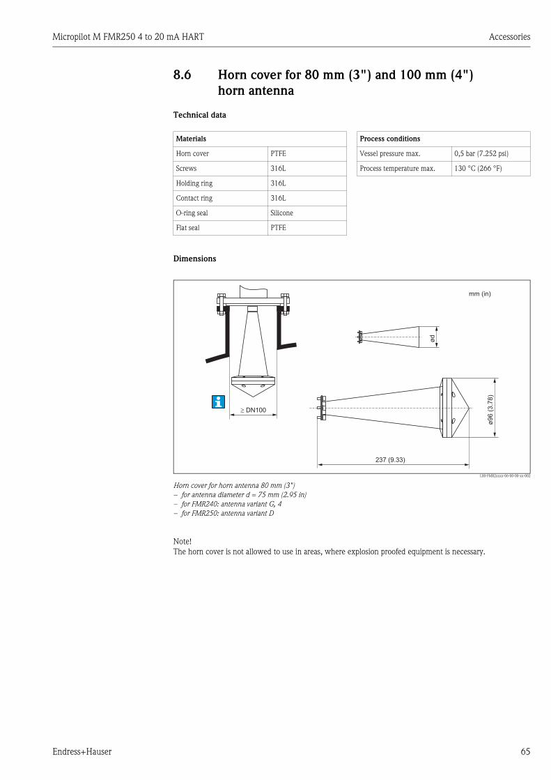
Micropilot M FMR250 4 to 20 mA HART Accessories
Endress+Hauser 65
8.6 Horn cover for 80 mm (3") and 100 mm (4")
horn antenna
Technical data
Dimensions
L00-FMR2xxxx-06-00-00-xx-002
Horn cover for horn antenna 80 mm (3")
– for antenna diameter d = 75 mm (2.95 in)
– for FMR240: antenna variant G, 4
– for FMR250: antenna variant D
Note!
The horn cover is not allowed to use in areas, where explosion proofed equipment is necessary.
Materials Process conditions
Horn cover PTFE Vessel pressure max. 0,5 bar (7.252 psi)
Screws 316L Process temperature max. 130 °C (266 °F)
Holding ring 316L
Contact ring 316L
O-ring seal Silicone
Flat seal PTFE
237 (9.33)
� DN100
mm (in)
ø96 (
3.7
8)
ød

Accessories Micropilot M FMR250 4 to 20 mA HART
66 Endress+Hauser
L00-FMR2xxxx-06-00-00-xx-003
Horn cover for horn antenna 100 mm (4")
– for antenna diameter d = 95 mm (3.74 in)
– for FMR240: antenna variant H, 5
– for FMR250: antenna variant E
Note!
The horn cover is not allowed to use in areas, where explosion proofed equipment is necessary.
Ordering information
450 (17.72)
Ø 1
16
(4.5
7)
Ø d
� DN150
mm (in)
Horn antenna 80 mm (3") 100 mm (4")
Order code 71105890 71105889
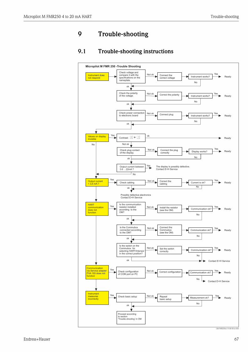
Micropilot M FMR250 4 to 20 mA HART Trouble-shooting
Endress+Hauser 67
9 Trouble-shooting
9.1 Trouble-shooting instructions
L00-FMR250xx-19-00-00-en-003
Instrument doesnot respond
Check voltage andcompare it with thespecifications on thenameplate.
Connect thecorrect voltage
Instrument works? Ready
Check the polarityof the voltage.
Check power connectionto electronic board
Correct the polarity
Connect plug
Instrument works?
Instrument works?
Ready
Ready
Values on displayinvisible
ok
ok
ok
Yes
Yes
Yes
No
No
No
No
Not ok
Not ok
Not ok
Check plug contactof the display.
Connect the plugcorrectly
Correct configuration
Display works? Ready
Ready
Yes
ok
No
Not ok
Yes
No
Micropilot M FMR 250 -Trouble Shooting
ok
Output current between3.6 …22mA ?
Contrast: F O+
The display is possibly defective.Contact E+H Service
Yes
Output current< 3,6 mA ?
No
Check cablingCorrect thecabling
Current is ok? ReadyYes
No
Possibly defective electronicsContact E+H Service
HARTcommunicationdoes notfunction
Is the communicationresistor installedaccording to theOM?
Install the resistor(see the OM)
Communication ok? Ready
Ready
ok
Yes
Yes
No
No
Connect theCommubox(see the OM)
Communication ok? Ready
Set the switchcorrectly
Communication ok Ready
Ready
Contact E+H Service
Contact E+H Service
ok
ok
ok
Yes
No
Yes
Yes
No
ok
Not ok
Not ok
Not ok
Not ok
Not ok
Not ok
?
Is the switch on theCommubox forselecting HART/Intensorin the correct position?
Is the Commuboxconnected accordingto the OM?
Communicationvia Service adapterFXA 193 does notfunction
Instrumentmeasuresincorrectly
Check configurationof COM port on PC
Check basic setup
Proceed accordingto section'Trouble shooting’ in OM
Repeatbasic setup
Not ok
Yes
Yes
Yes
Yes
Communication ok?
Measurement ok?
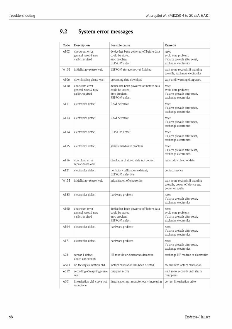
Trouble-shooting Micropilot M FMR250 4 to 20 mA HART
68 Endress+Hauser
9.2 System error messages
Code Description Possible cause Remedy
A102 checksum error
general reset & new
calibr.required
device has been powered off before data
could be stored;
emc problem;
EEPROM defect
reset;
avoid emc problem;
if alarm prevails after reset,
exchange electronics
W103 initialising - please wait EEPROM storage not yet finished wait some seconds; if warning
prevails, exchange electronics
A106 downloading please wait processing data download wait until warning disappears
A110 checksum error
general reset & new
calibr.required
device has been powered off before data
could be stored;
emc problem;
EEPROM defect
reset;
avoid emc problem;
if alarm prevails after reset,
exchange electronics
A111 electronics defect RAM defective reset;
if alarm prevails after reset,
exchange electronics
A113 electronics defect RAM defective reset;
if alarm prevails after reset,
exchange electronics
A114 electronics defect EEPROM defect reset;
if alarm prevails after reset,
exchange electronics
A115 electronics defect general hardware problem reset;
if alarm prevails after reset,
exchange electronics
A116 download error
repeat download
checksum of stored data not correct restart download of data
A121 electronics defect no factory calibration existant;
EEPROM defective
contact service
W153 initialising - please wait initialisation of electronics wait some seconds; if warning
prevails, power off device and
power on again
A155 electronics defect hardware problem reset;
if alarm prevails after reset,
exchange electronics
A160 checksum error
general reset & new
calibr.required
device has been powered off before data
could be stored;
emc problem;
EEPROM defect
reset;
avoid emc problem;
if alarm prevails after reset,
exchange electronics
A164 electronics defect hardware problem reset;
if alarm prevails after reset,
exchange electronics
A171 electronics defect hardware problem reset;
if alarm prevails after reset,
exchange electronics
A231 sensor 1 defect
check connection
HF module or electronics defective exchange HF module or electronics
W511 no factory calibration ch1 factory calibration has been deleted record new factory calibration
A512 recording of mapping please
wait
mapping active wait some seconds until alarm
disappears
A601 linearisation ch1 curve not
monotone
linearisation not monotonously increasing correct linearisation table

Micropilot M FMR250 4 to 20 mA HART Trouble-shooting
Endress+Hauser 69
W611 less than 2 linearisation
points for channel 1
number of entered linearisation points < 2 correct linearisation table
W621 simulation ch. 1 on simulation mode is active switch off simulation mode
E641 no usable echo
channel 1
check calibr.
echo lost due to application conditions or
built up on antenna
check installation;
optimize orientation of antenna;
clean antenna (cf. OM)
E651 level in safety distance - risk
of overspill
level in safety distance alarm will disappear as soon as level
leaves safety distance;
E671 linearisation ch1 not
complete, not usable
linearisation table is in edit mode activate linearisation table
W681 current ch1 out of range current out of range (3.8 mA to 20.5 mA) check calibration and linearisation
Code Description Possible cause Remedy
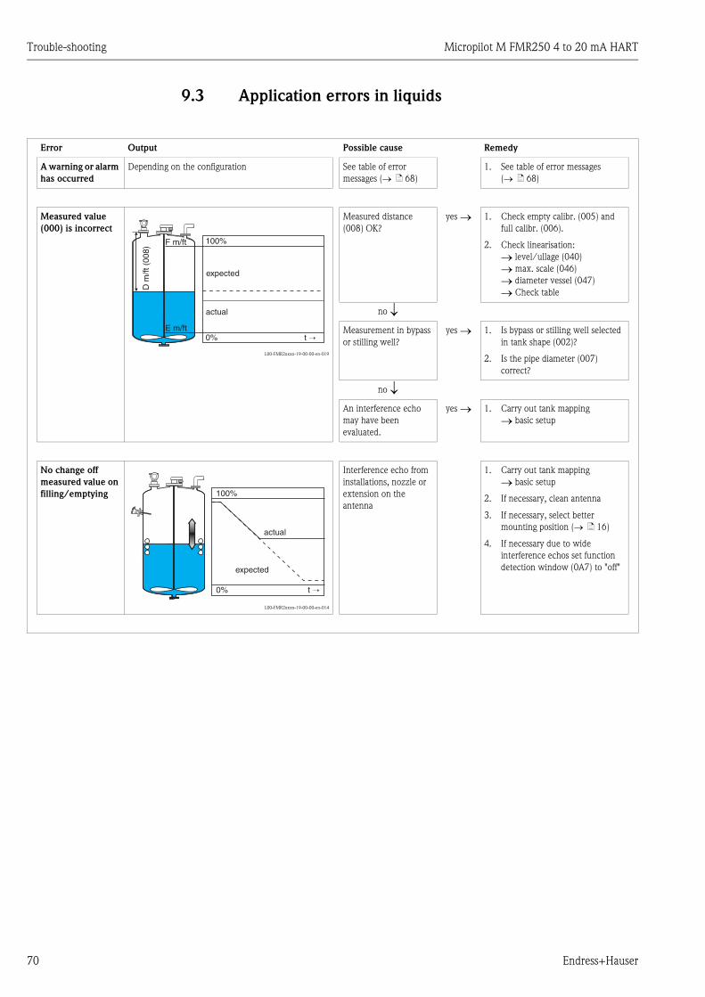
Trouble-shooting Micropilot M FMR250 4 to 20 mA HART
70 Endress+Hauser
9.3 Application errors in liquids
Error Output Possible cause Remedy
A warning or alarm
has occurred
Depending on the configuration See table of error
messages (→ ä 68)
1. See table of error messages
(→ ä 68)
Measured value
(000) is incorrect
L00-FMR2xxxx-19-00-00-en-019
Measured distance
(008) OK?
yes → 1. Check empty calibr. (005) and
full calibr. (006).
2. Check linearisation:
→ level/ullage (040)
→ max. scale (046)
→ diameter vessel (047)
→ Check table
no ↓Measurement in bypass
or stilling well?
yes → 1. Is bypass or stilling well selected
in tank shape (002)?
2. Is the pipe diameter (007)
correct?
no ↓An interference echo
may have been
evaluated.
yes → 1. Carry out tank mapping
→ basic setup
No change off
measured value on
filling/emptying
L00-FMR2xxxx-19-00-00-en-014
Interference echo from
installations, nozzle or
extension on the
antenna
1. Carry out tank mapping
→ basic setup
2. If necessary, clean antenna
3. If necessary, select better
mounting position (→ ä 16)
4. If necessary due to wide
interference echos set function
detection window (0A7) to "off"
100%F m/ft
E m/ft0% t →
D m
/ft (
008)
actual
expected
100%
0% t →
actual
expected

Micropilot M FMR250 4 to 20 mA HART Trouble-shooting
Endress+Hauser 71
Error Output Possible cause Remedy
If the surface is not
calm (e.g. filling,
emptying, agitator
running), the
measured value
jumps sporadically
to a higher level
L00-FMR2xxxx-19-00-00-en-015
L00-FMR2xxxx-19-00-00-en-016
Signal is weakened by
the rough surface – the
interference echoes are
sometimes stronger
1. Carry out tank mapping → basic
setup
2. Set the process cond. (004) to
"turb. surface" or "agitator"
3. Increase the output damping
(058)
4. Optimise the orientation
(→ ä 74)
5. If necessary, select a better
mounting position and/or larger
antenna (→ ä 16)
During filling/
emptying the
measured value
jumps ownwards
L00-FMR2xxxx-19-00-00-en-017
Multiple echoes yes → 1. Check the tank shape (002), e.g.
"dome ceiling" or "horizontal
cyl"
2. In the range of the blocking dist.
(059) there is no echo evaluation
→ Adapt the value
3. If possible, do not select central
installation position (→ ä 16)
4. Perhaps use a stilling well
E641 (loss of echo)
L00-FMR2xxxx-19-00-00-en-018
Level echo is too weak.
Possible causes:
• Rough surface due to
filling/ emptying
• Agitator running
• Foam
yes → 1. Check application arameters
(002), (003) and (004)
2. Optimise alignment (→ ä 74)
3. If necessary, select a better
installation position and/or larger
antenna (→ ä 16)
100%
0% t →
actual
expected
100%
0% t →
actual
expected
100%
0% t →
actual
expected
100%
E 641
0% t →
eingetreten
erwartet
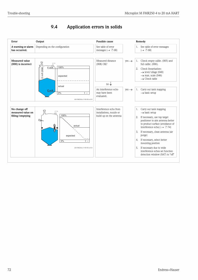
Trouble-shooting Micropilot M FMR250 4 to 20 mA HART
72 Endress+Hauser
9.4 Application errors in solids
Error Output Possible cause Remedy
A warning or alarm
has occurred.
Depending on the configuration See table of error
messages (→ ä 68)
1. See table of error messages
(→ ä 68)
Measured value
(000) is incorrect
L00-FMR250xx-19-00-00-en-019
Measured distance
(008) OK?
yes → 1. Check empty calibr. (005) and
full calibr. (006).
2. Check linearisation:
→ level/ullage (040)
→ max. scale (046)
→ Check table
no ↓An interference echo
may have been
evaluated.
yes → 1. Carry out tank mapping
→ basic setup
No change off
measured value on
filling/emptying
L00-FMR250xx-19-00-00-en-014
Interference echo from
installations, nozzle or
build up on the antenna
1. Carry out tank mapping
→ basic setup
2. If necessary, use top target
positioner to aim antenna better
to product surface (avoidance of
interference echo) (→ ä 74)
3. If necessary, clean antenna (air
purge)
4. If necessary, select better
mounting position
5. If necessary due to wide
interference echos set function
detection window (0A7) to "off"
100%F m/ft
E m/ft0% t →
D m
/ft (
008)
actual
expected
100%
0% t →
actual
expected
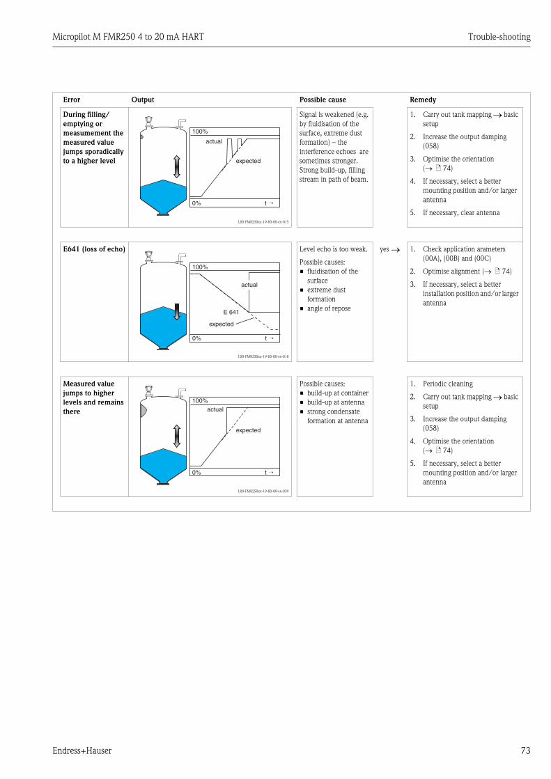
Micropilot M FMR250 4 to 20 mA HART Trouble-shooting
Endress+Hauser 73
Error Output Possible cause Remedy
During filling/
emptying or
measumement the
measured value
jumps sporadically
to a higher level
L00-FMR250xx-19-00-00-en-015
Signal is weakened (e.g.
by fluidisation of the
surface, extreme dust
formation) – the
interference echoes are
sometimes stronger.
Strong build-up, filling
stream in path of beam.
1. Carry out tank mapping → basic
setup
2. Increase the output damping
(058)
3. Optimise the orientation
(→ ä 74)
4. If necessary, select a better
mounting position and/or larger
antenna
5. If necessary, clear antenna
E641 (loss of echo)
L00-FMR250xx-19-00-00-en-018
Level echo is too weak.
Possible causes:
• fluidisation of the
surface
• extreme dust
formation
• angle of repose
yes → 1. Check application arameters
(00A), (00B) and (00C)
2. Optimise alignment (→ ä 74)
3. If necessary, select a better
installation position and/or larger
antenna
Measured value
jumps to higher
levels and remains
there
L00-FMR250xx-19-00-00-en-039
Possible causes:
• build-up at container
• build-up at antenna
• strong condensate
formation at antenna
1. Periodic cleaning
2. Carry out tank mapping → basic
setup
3. Increase the output damping
(058)
4. Optimise the orientation
(→ ä 74)
5. If necessary, select a better
mounting position and/or larger
antenna
100%
0% t →
actual
expected
100%
E 641
0% t →
actual
expected
100%
0% t →
actual
expected

Trouble-shooting Micropilot M FMR250 4 to 20 mA HART
74 Endress+Hauser
9.5 Orientation of the Micropilot
For orientation a marker is found on the flange or threaded boss of the Micropilot. During
installation this must be oriented as follows (→ ä 10):
• In tanks: to the vessel wall
• In stilling wells: to the slots
• In bypass pipes: vertical to the tank connectors
• When using the Wave Guide antenna no orientation is required!
After commissioning the Micropilot, the echo quality indicates whether a sufficiently large
measuring signal is obtained. If necessary, the quality can be optimised later. Vice versa, the
presence of an interference echo can be used to minimise this by optimum orientation. The
advantage of this is that the subsequent tank mapping uses a somewhat lower level that causes an
increase in the strength of the measuring signal. Proceed as follows:
# Warning!
Subsequent alignment can lead to personal injury. Before you unscrew or loosen the process
connection, make sure that the vessel is not under pressure and does not contain any injurious
substances.
1. It is best to empty the container so that the bottom is just covered. However, alignment can be
carried out even if the vessel is empty.
2. Optimisation is best carried out with the aid of the envelope graph in the display or the
FieldCare.
3. Unscrew the flange or loosen the threaded boss by a half a turn.
4. Turn the flange by one hole or screw the threaded boss by one eighth of a turn. Note the echo
quality.
5. Continue to turn until 360° is reached.
6. Optimum alignment:
L00-FMRxxxxx-19-00-00-en-002
Vessel partly full, no interference echo obtained
L00-FMRxxxxx-19-00-00-en-003
Vessel partly full, interference echo obtained:

Micropilot M FMR250 4 to 20 mA HART Trouble-shooting
Endress+Hauser 75
L00-FMRxxxxx-19-00-00-en-004
Vessel empty, no interference echo
L00-FMRxxxxx-19-00-00-en-005
Vessel empty, interference echo obtained
7. Fix the flange or threaded boss in this position. If necessary, replace the seal.
8. Carry out tank mapping, → ä 52.
Top target positioner - optional
Using top target positioner it is possible to tilt the antenna axis by up to 15° in all directions. The
top target positioner is used for the optimum alignment of the radar beam with the bulk solids
surface.
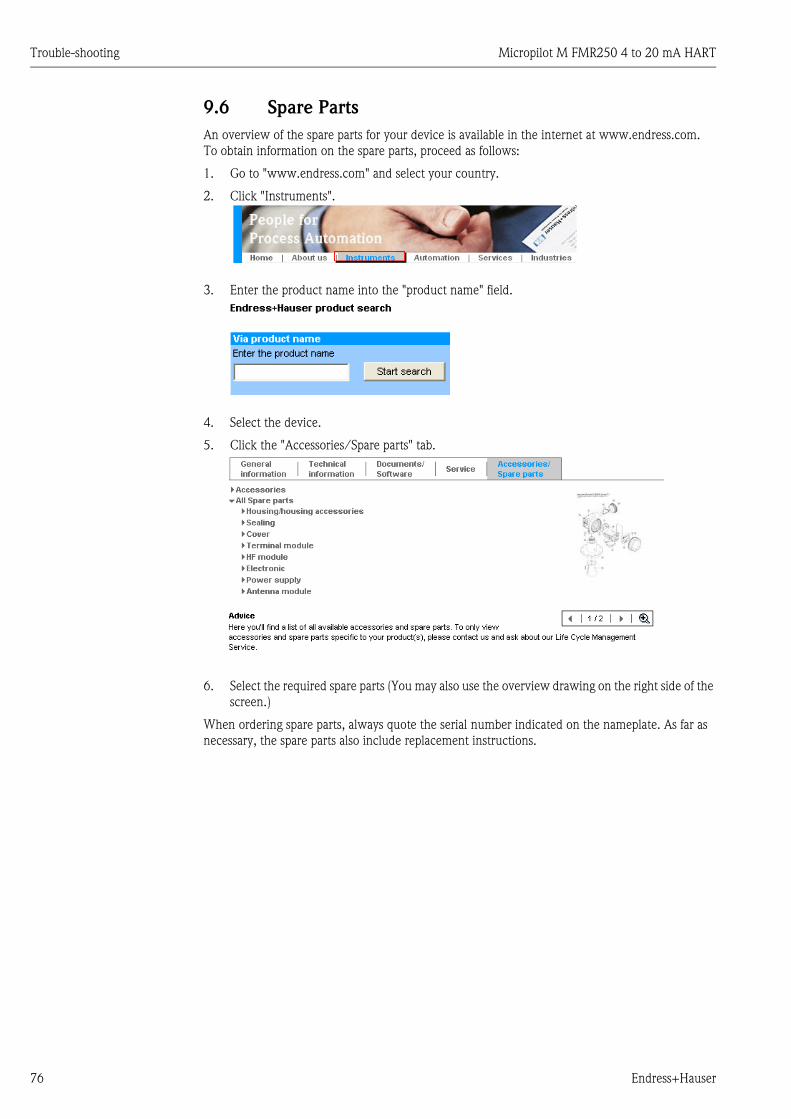
Trouble-shooting Micropilot M FMR250 4 to 20 mA HART
76 Endress+Hauser
9.6 Spare Parts
An overview of the spare parts for your device is available in the internet at www.endress.com.
To obtain information on the spare parts, proceed as follows:
1. Go to "www.endress.com" and select your country.
2. Click "Instruments".
3. Enter the product name into the "product name" field.
4. Select the device.
5. Click the "Accessories/Spare parts" tab.
6. Select the required spare parts (You may also use the overview drawing on the right side of the
screen.)
When ordering spare parts, always quote the serial number indicated on the nameplate. As far as
necessary, the spare parts also include replacement instructions.
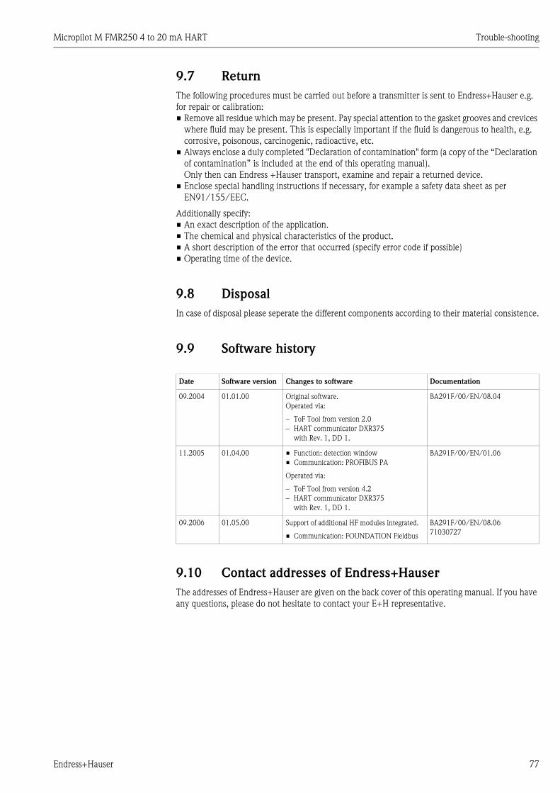
Micropilot M FMR250 4 to 20 mA HART Trouble-shooting
Endress+Hauser 77
9.7 Return
The following procedures must be carried out before a transmitter is sent to Endress+Hauser e.g.
for repair or calibration:
• Remove all residue which may be present. Pay special attention to the gasket grooves and crevices
where fluid may be present. This is especially important if the fluid is dangerous to health, e.g.
corrosive, poisonous, carcinogenic, radioactive, etc.
• Always enclose a duly completed "Declaration of contamination" form (a copy of the “Declaration
of contamination” is included at the end of this operating manual).
Only then can Endress +Hauser transport, examine and repair a returned device.
• Enclose special handling instructions if necessary, for example a safety data sheet as per
EN91/155/EEC.
Additionally specify:
• An exact description of the application.
• The chemical and physical characteristics of the product.
• A short description of the error that occurred (specify error code if possible)
• Operating time of the device.
9.8 Disposal
In case of disposal please seperate the different components according to their material consistence.
9.9 Software history
9.10 Contact addresses of Endress+Hauser
The addresses of Endress+Hauser are given on the back cover of this operating manual. If you have
any questions, please do not hesitate to contact your E+H representative.
Date Software version Changes to software Documentation
09.2004 01.01.00 Original software.
Operated via:
– ToF Tool from version 2.0
– HART communicator DXR375
with Rev. 1, DD 1.
BA291F/00/EN/08.04
11.2005 01.04.00 • Function: detection window
• Communication: PROFIBUS PA
Operated via:
– ToF Tool from version 4.2
– HART communicator DXR375
with Rev. 1, DD 1.
BA291F/00/EN/01.06
09.2006 01.05.00 Support of additional HF modules integrated.
• Communication: FOUNDATION Fieldbus
BA291F/00/EN/08.06
71030727

Technical data Micropilot M FMR250 4 to 20 mA HART
78 Endress+Hauser
10 Technical data
10.1 Additional technical data
10.1.1 Input
Measured variable The measured variable is the distance between a reference point and a reflective surface (i.e.
medium surface). The level is calculated based on the tank height entered. The level can be
converted into other units (volume, mass) by means of a linearization (32 points).
Operating frequency • K-band
Transmitting power
10.1.2 Output
Output signal 4 to 20 mA (invertible) with HART protocol
Signal coding FSK ±0.5 mA over currency signal
Data transmission rate 1200 Baud
Galvanic isolation Yes (IO-Module)
Signal on alarm Error information can be accessed via the following interfaces:
• Local display:
– Error symbol (→ ä 35)
– Plain text display
• Current output, signal on error can be selected (e.g. according to NAMUR recommendation NE43)
• Digital interface
Linearization The linearization function of the Micropilot M allows the conversion of the measured value into any
unit of length or volume. Linearization tables for calculating the volume in cylindrical tanks are pre-
programmed. Other tables of up to 32 value pairs can be entered manually or semi-automatically.
10.1.3 Auxiliary energy
Ripple HART 47...125 Hz: Uss = 200 mV (at 500 Ω)
Max. noise HART 500 Hz...10 kHz: Ueff = 2.2 mV (at 500 Ω)
DistanceAverage energy density in beam direction
measuring range = 70 m (230 ft)
1 m (3.3 ft) < 64 nW/cm2
5 m (16 ft) < 2.5 nW/cm2

Micropilot M FMR250 4 to 20 mA HART Technical data
Endress+Hauser 79
10.1.4 Performance characteristics
Reference operating
conditions
• temperature = +20 °C ±5 °C (+68 °F ±41 °F)
• pressure = 1013 mbar abs. ±20 mbar (15.19 psi ±0.3 psi)
• relative humidity (air) = 65 % ±20 %
• ideal reflector
• no major interference reflections inside the signal beam
Maximum measured error Typical statements for reference conditions, include linearity, repeatability, and hysteresis:
• up to 1 m (3.3 ft): ±30 mm (1.18 in)
• ex 1 m (3.3 ft): ±15 mm (0.59 in) (or 0.04% of measuring range, whatever is larger)
Resolution Digital / analog in % 4 to 20 mA: 1mm (0.04 in) / 0.03 % of measuring range
Reaction time The reaction time depends on the parameter settings (min. 1 s). In case of fast level changes, the
instrument needs the reaction time to indicate the new value.
Influence of ambiente
temperature
The measurements are carried out in accordance with EN61298-3:
• digital output HART:
– average TK: 5 mm (0.2 in) /10 K, max. 15 mm (0.59 in) over the entire temperature range
-40 °C to +80 °C (-40 °F to +176 °F).
• Current output (additional error, in reference to the span of 16 mA):
– Zero point (4 mA)
average TK: 0,03 %/10 K, max. 0,45 % over the entire temperature range
-40 °C to +80 °C (-40 °F to +176 °F).
– Span (20 mA)
average TK: 0,09 %/10 K, max. 0,95 % over the entire temperature range
-40 °C to +80 °C (-40 ° to +176 °F).
10.1.5 Operating conditions: Environment
Ambient temperature range Ambient temperature for the transmitter: -40 °C to +80 °C (-40 ° to +176 °F) or
-50 °C to +80 °C (-58 °F to +176 °F). The functionality of the LCD display may be limited for
temperatures Ta < -20 °C (-4 °F) and Ta > +60 °C (140 °F). A weather protection cover should be
used for outdoor operation if the instrument is exposed to direct sunlight.
Storage temperature -40 °C to +80 °C (-40 ° to +176 °F) or -50 °C to +80 °C (-58 °F to +176 °F).
Climate class DIN EN 60068-2-38 (test Z/AD)
Vibration resistance DIN EN 60068-2-64 / IEC 68-2-64: 20…2000 Hz, 1 (m/s2)2/Hz
Cleaning of the antenna The antenna can get contaminated, depending on the application. The emission and reception of
microwaves can thus eventually be hindered. The degree of contamination leading to an error
depends on the medium and the reflectivity, mainly determined by the dielectric constant εr. If the
medium tends to cause contamination and deposits, cleaning on a regular basis is recommended.
Care has to be taken not to damage the antenna in the process of a mechanical or hose-down
cleaning (eventually air purge connection). The material compatibility has to be considered if
cleaning agents are used!
The maximum permitted temperature at the flange should not be exceeded.

Technical data Micropilot M FMR250 4 to 20 mA HART
80 Endress+Hauser
Electromagnetic compatibility • Electromagnetic compatibility in accordance with all the relevant requirements of the EN61326
series and NAMUR recommendation (NE21). For details refer to the Declaration of Conformity.
Maximum deviation < 0.5 % of the span.
• A standard installation cable is sufficient if only the analogue signal is used. Use a screened cable
when working with a superimposed communications signal (HART).
10.1.6 Operating conditions: Process
Process temperature range /
Process pressure limits
Note!
The specific range may be reduces by the selected process condition. The pressure rating (PN)
specified on flanges refers to a reference temperature of 20 °C (68 °F), for ASME flanges to 100 °F.
Observe pressure temperature dependency.
The pressure values permitted at higher temperatures can be found in the following standards:
• EN1092-1: 2001 Tab.18
With regard to their temperature stability properties, the materials 1.4404 and 1.4435 are
grouped unter 13E0 in EN1092-1 Tab. 18. The chemical composition of the two materials can
be identical.
• ASME B16.5a - 1998 Tab. 2-2.2 F316
• ASME B16.5a - 1998 Tab. 2.3.8 N10276
• JIS B2220
Optional top target positioner: ±15°, seal: FMK Viton GLT
Dielectric constant • in free space: εr ≥ 1.6 (for horizontal, even product surfaces: εr ≥ 1.4)
Feature "20 Antenna:" Seal Temperature Pressure 1)
1) E+H UNI flange: -1 bar to 1 bar (-14.5 psi to 14.5 psi)
Wetted parts
Type Option Size
Horn 4
5
D
E
80 mm (3")
100 mm (4")
80 mm (3")
100 mm (4")
FKM Viton GLT -40 °C to +200 °C
(-40 °F to +392 °F)
-1 bar to 16 bar
(-14.5 psi to 232 psi)
PEEK, seal,
316L/1.4404/
1.4435
Parabolic G
H
200 mm (8")
250 mm (10")
FKM Viton GLT -40 °C to +200 °C
(-40 °F to +392 °F)
-1 bar to 16 bar
(-14.5 psi to 232 psi)
PTFE, seal,
316L/1.4404/
1.4435
↑ Ordering information, → ä 6
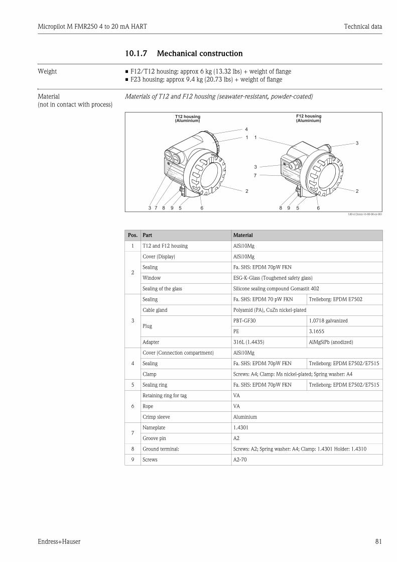
Micropilot M FMR250 4 to 20 mA HART Technical data
Endress+Hauser 81
10.1.7 Mechanical construction
Weight • F12/T12 housing: approx 6 kg (13.32 lbs) + weight of flange
• F23 housing: approx 9.4 kg (20.73 lbs) + weight of flange
Material
(not in contact with process)
Materials of T12 and F12 housing (seawater-resistant, powder-coated)
L00-x12xxxx-16-00-00-en-001
Pos. Part Material
1 T12 and F12 housing AlSi10Mg
2
Cover (Display) AlSi10Mg
Sealing Fa. SHS: EPDM 70pW FKN
Window ESG-K-Glass (Toughened safety glass)
Sealing of the glass Silicone sealing compound Gomastit 402
3
Sealing Fa. SHS: EPDM 70 pW FKN Trelleborg: EPDM E7502
Cable gland Polyamid (PA), CuZn nickel-plated
PlugPBT-GF30 1.0718 galvanized
PE 3.1655
Adapter 316L (1.4435) AlMgSiPb (anodized)
4
Cover (Connection compartment) AlSi10Mg
Sealing Fa. SHS: EPDM 70pW FKN Trelleborg: EPDM E7502/E7515
Clamp Screws: A4; Clamp: Ms nickel-plated; Spring washer: A4
5 Sealing ring Fa. SHS: EPDM 70pW FKN Trelleborg: EPDM E7502/E7515
6
Retaining ring for tag VA
Rope VA
Crimp sleeve Aluminium
7Nameplate 1.4301
Groove pin A2
8 Ground terminal: Screws: A2; Spring washer: A4; Clamp: 1.4301 Holder: 1.4310
9 Screws A2-70
(Aluminium) (Aluminium)
ENDRESS+HAUSER
IP 65
Order Code:Ser.-No.:
MessbereichMeasuring rangeU 16...36 V DC
4...20 mA
max. 20 m
Ma
de
in G
erm
any
Ma
ulb
urg
Ma
de
in G
erm
any
Ma
ulb
urg
T>70°C :
A
t >85°C
Ma
de
in G
erm
any
Ma
ulb
urg
Ma
de
in G
erm
any
Ma
ulb
urg
ENDRESS+HAUSER
IP 65
Order Code:Ser.-No.:
MessbereichMeasuring rangeU 16...36 V DC
4...20 mA
max. 20 m
Ma
de
in G
erm
any
Ma
ulb
urg
Ma
de
in G
erm
any
Ma
ulb
urg
T>70°C :
A
t >85°C
F12 housingT12 housing
987 5 6 98 5 6
3
2
1
4
2
1
3
3
7

Technical data Micropilot M FMR250 4 to 20 mA HART
82 Endress+Hauser
Materials of F23 housing (corrosion-resistant)
L00-x12xxxx-16-00-00-en-001
Pos. Part Material
1 F23 housingHousing body: 1.4404; Sensor neck: 1.4435;
earth connection block: 1.4435
2
Cover 1.4404
Sealing Fa. SHS: EPDM 70pW FKN
Window ESG-K-Glass (Toughened safety glass)
Sealing of the glass Silicone sealing compound Gomastit 402
3
Sealing Fa. SHS: EPDM 70pW FKN Trelleborg: EPDM E7502
Cable gland Polyamid (PA), CuZn nickel-plated
PlugPBT-GF30 1.0718 galvanized
PE 3.1655
Adapter 316L (1.4435)
4 Sealing ring Fa. SHS: EPDM 70pW FKN Trelleborg: EPDM E7502
5 Nameplate 1.4301
6 Grounding terminal: Screws: A2; Spring washer: A4; Clamp: 1.4301; Holder: 1.4310
7 Screw A2-70
8
Retaining ring for tag VA
Rope VA
Crimp sleeve Aluminium
316L (1.4404/1.4435)F23 housing
6 7 48
1
3
5
2
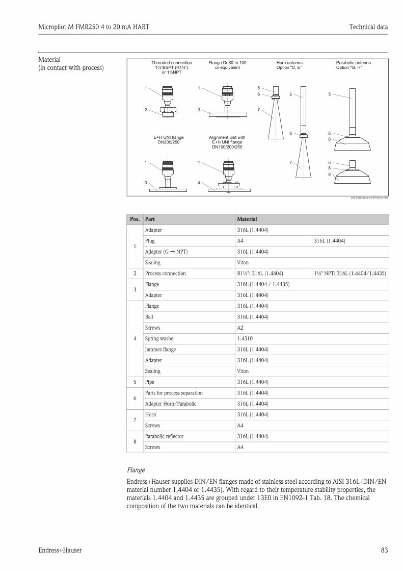
Micropilot M FMR250 4 to 20 mA HART Technical data
Endress+Hauser 83
Material
(in contact with process)
L00-FMR250xx-16-00-00-en-001
Flange
Endress+Hauser supplies DIN/EN flanges made of stainless steel according to AISI 316L (DIN/EN
material number 1.4404 or 1.4435). With regard to their temperature stability properties, the
materials 1.4404 and 1.4435 are grouped under 13E0 in EN1092-1 Tab. 18. The chemical
composition of the two materials can be identical.
Pos. Part Material
1
Adapter 316L (1.4404)
Plug A4 316L (1.4404)
Adapter (G È NPT) 316L (1.4404)
Sealing Viton
2 Process connection R1½": 316L (1.4404) 1½" NPT: 316L (1.4404/1.4435)
3Flange 316L (1.4404 / 1.4435)
Adapter 316L (1.4404)
4
Flange 316L (1.4404)
Ball 316L (1.4404)
Screws A2
Spring washer 1.4310
Jammes flange 316L (1.4404)
Adapter 316L (1.4404)
Sealing Viton
5 Pipe 316L (1.4404)
6Parts for process separation 316L (1.4404)
Adapter Horn/Parabolic 316L (1.4404)
7Horn 316L (1.4404)
Screws A4
8Parabolic reflector 316L (1.4404)
Screws A4
Parabolic antennaOption “G, H”
Horn antennaOption “D, E”
Threaded connectionBSPT (R1½”)or 1½NPT
1½”Flange Dn80 to 100
or equivalent
E+H UNI flangeDN200/250
Alignment unit withE+H UNI flangeDN100/200/250
1
2
1 5
6
7
5 5
6
7
6
8
5
6
8
3
1
3
1
4
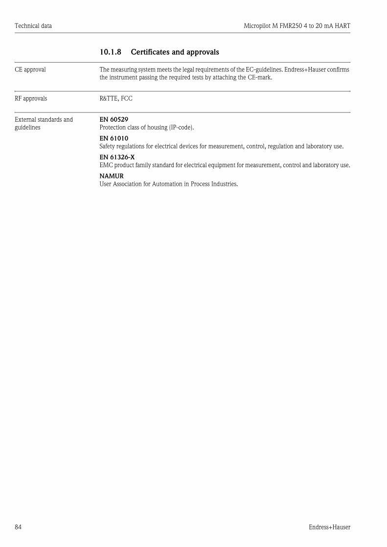
Technical data Micropilot M FMR250 4 to 20 mA HART
84 Endress+Hauser
10.1.8 Certificates and approvals
CE approval The measuring system meets the legal requirements of the EC-guidelines. Endress+Hauser confirms
the instrument passing the required tests by attaching the CE-mark.
RF approvals R&TTE, FCC
External standards and
guidelines
EN 60529
Protection class of housing (IP-code).
EN 61010
Safety regulations for electrical devices for measurement, control, regulation and laboratory use.
EN 61326-X
EMC product family standard for electrical equipment for measurement, control and laboratory use.
NAMUR
User Association for Automation in Process Industries.
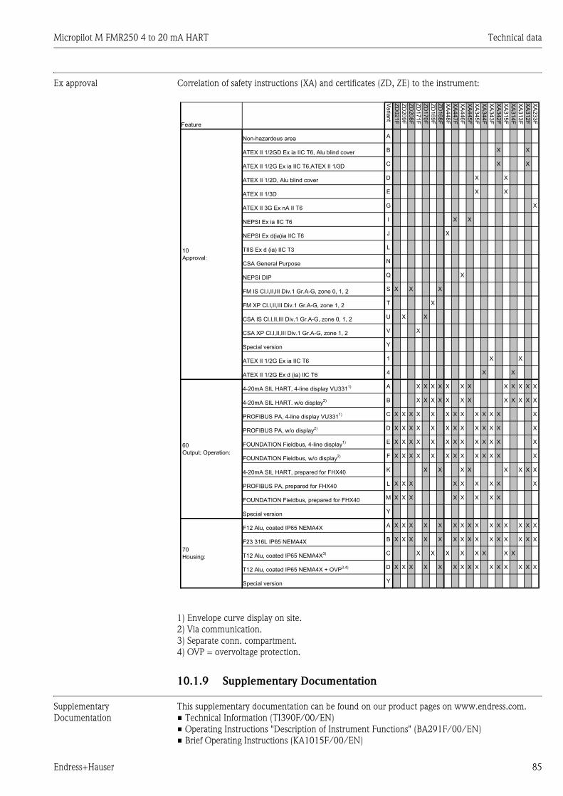
Micropilot M FMR250 4 to 20 mA HART Technical data
Endress+Hauser 85
Ex approval Correlation of safety instructions (XA) and certificates (ZD, ZE) to the instrument:
1) Envelope curve display on site.
2) Via communication.
3) Separate conn. compartment.
4) OVP = overvoltage protection.
10.1.9 Supplementary Documentation
Supplementary
Documentation
This supplementary documentation can be found on our product pages on www.endress.com.
• Technical Information (TI390F/00/EN)
• Operating Instructions "Description of Instrument Functions" (BA291F/00/EN)
• Brief Operating Instructions (KA1015F/00/EN)
XA
23
3F
X
X
X
X
X
X
X
X
X
X
X
X
XA
31
2F
X
X
X
X
X
X
X
X
XA
31
3F
X
X
X
X
X
X
X
XA
31
4F
X
X
X
X
XA
31
5F
X
X
X
X
X
X
X
X
X
XA
34
2F
X
X
X
X
X
X
X
X
X
X
X
XA
34
3F
X
X
X
X
X
X
X
X
X
X
XA
34
4F
X
X
X
X
X
X
XA
34
5F
X
X
X
X
X
X
X
X
X
X
X
X
XA
44
5F
X
X
X
X
X
X
X
XA
44
6F
X
X
X
X
X
X
X
X
X
X
X
X
X
X
XA
44
7F
X
X
X
X
X
X
X
X
X
X
XA
44
8F
X
X
X
X
X
X
X
X
ZD
16
8F
X
X
X
X
X
X
X
ZD
16
9F
X
X
X
X
X
X
X
X
ZD
17
0F
X
X
X
X
X
X
X
ZD
17
1F
X
X
X
X
X
X
X
X
ZD
20
8F
X
X
X
X
X
X
X
X
X
X
ZD
20
9F
X
X
X
X
X
X
X
X
X
X
ZD
02
1F
X
X
X
X
X
X
X
X
X
X
Va
rian
t
A
B
C
D
E
G
I
J
L
N
Q
S
T
U
V
Y
1
4
A
B
C
D
E
F
K
L
M
Y
A
B
C
D
Y
Non-hazardous area
ATEX II 1/2GD Ex ia IIC T6, Alu blind cover
ATEX II 1/2G Ex ia IIC T6,ATEX II 1/3D
ATEX II 1/2D, Alu blind cover
ATEX II 1/3D
ATEX II 3G Ex nA II T6
NEPSI Ex ia IIC T6
NEPSI Ex d(ia)ia IIC T6
TIIS Ex d (ia) IIC T3
CSA General Purpose
NEPSI DIP
FM IS Cl.I,II,III Div.1 Gr.A-G, zone 0, 1, 2
FM XP Cl.I,II,III Div.1 Gr.A-G, zone 1, 2
CSA IS Cl.I,II,III Div.1 Gr.A-G, zone 0, 1, 2
CSA XP Cl.I,II,III Div.1 Gr.A-G, zone 1, 2
Special version
ATEX II 1/2G Ex ia IIC T6
ATEX II 1/2G Ex d (ia) IIC T6
4-20mA SIL HART, 4-line display VU3311)
4-20mA SIL HART. w/o display2)
PROFIBUS PA, 4-line display VU3311)
PROFIBUS PA, w/o display2)
FOUNDATION Fieldbus, 4-line display1)
FOUNDATION Fieldbus, w/o display2)
4-20mA SIL HART, prepared for FHX40
PROFIBUS PA, prepared for FHX40
FOUNDATION Fieldbus, prepared for FHX40
Special version
F12 Alu, coated IP65 NEMA4X
F23 316L IP65 NEMA4X
T12 Alu, coated IP65 NEMA4X3)
T12 Alu, coated IP65 NEMA4X + OVP3,4)
Special version
Feature
10
Approval:
60
Output; Operation:
70
Housing:

Appendix Micropilot M FMR250 4 to 20 mA HART
86 Endress+Hauser
11 Appendix
11.1 Operating menu HART
L00-FMR250xx-19-00-01-en-036
safety settings
basic setup
output on alarm
MIN -10% 3.6mA
holdMAX 110% 22mA
tank shape
vessel / silo
media typedome ceilinghorizontal cyl.
unknownmetal siloconcrete silobin / bunkerdomestockpileconveyor belt
liquid
solidbypassstilling wellflat ceilingsphere
level/ullage
level DUullage DU
level CUullage CU
selectionmapping
common
extended map..
commun. address
present error
tag no.
fixed cur. value
4mA value 20mA value
enter value
medium cond.
medium cond.
unknownDK: < 1.9DK: 1.9 … 4DK: 4 … 10DK: > 10
unknownDC: 1.6 ... 1.9DC: 1.9 … 2.5DC: 2.5 … 4DC: 4 … 7DC: > 7
linearisation
manualsemi-automatictable on
horicontal cyllinearclear table
dist./meas valueD and Lare displayed
no. of preambels
language
previous error
outp. echo loss
alarmhold
ramp %MB/min
process cond.
process cond.
standardcalm surfaceturb. surfaceadd. agitatorfast changetest: no filter
standardfast changeslow changetest: no filter
customer unittable no.input levelinput volume
customer unit
customer unit
check distancedistance = okdist. too smallmanualdist. unknowndist. too big
low output limitoffon
back to homeenter timedefault: 100 s
clear last error
protocol+sw-no.
plot settingsenvelope curveenv.curve+FACenv.curve+cust.map
ramp %span/min
empty calibr.
empty calibr.
enter value
enter value
linearisation
range of mapping
pres. Map dist
input ofmapping range
is displayed
curr. output mode
format displaydecimal
resetfor reset codesee manual
recording curvesingle curvecyclic
Note! The default values of the parameters are typed in boldface.
delay time
in case of echo lossmax. 4000 sec.default: 30 s
full calibr.
full calibr.
enter value
enter value
next point
yes
no
start mapping
cust. Tank map
offon
inactiveactivereset
no. of decimalsxx.xx.xxx.xxx
unlock parameterfor reset codesee manual
serial no.
linearisation
extended calibr.
output
envelope curve
display
diagnostics
system parameter
01
00
010
002
00A
001
040
040
040
050
060
0A0
0C0
003
00B
041
041
008
061
092
0A1
012
004
00C
042043044045
042
042
051
062
093
0A2
0C2
0E1
013
005
005
052
054
063
094
0A3
0E2
014
006
006
045
053
055
064
068 069
095
0A4
0C4
04
05
06
0E
09
0A
0C
1/16”
user specific output on alarmenter value
011
standard
fixed current
fixed current
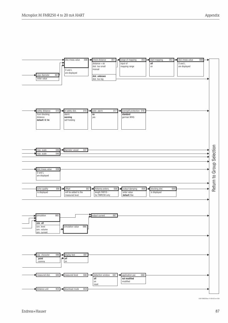
Micropilot M FMR250 4 to 20 mA HART Appendix
Endress+Hauser 87
L00-FMR250xx-19-00-02-en-036
dist./meas.valueD and Lare displayed
simulation
sim. offsim. levelsim. volumesim. current
sep. character
. point, comma
measured dist.
distance unit
max. scale
max. scale
safety distancefrom blockingdistancedefault: 0.1m
dist./meas.value
D and Lare displayed
echo qualityis displayed
simulation value
display test
offon
measured level
download mode
diameter vessel
in safety dist.alarm
self holdingwarning
check distance
distance = okdist. too smallmanual
dist. unknowndist. too big
offsetwill be added to themeasured level
output current
ackn. alarm overspill protectionnoyes
standardgerman WHG
range of mapping
input ofmapping range
output dampingAntenna extens.enter valuedefault: 5 s
length FAR10 -for FMR230 only
application par.detection window
Retu
rn to
Gro
up S
elec
tion
not modifiedmodified
offonreset
start mapping
offon
pipe diameterenter value
blocking dist.is displayed
dist./meas.value
D and Lare displayed
008
065
096
0A5
0C5
046
046
015
008
056
066
097
0A6
0C8
047
016
051
057
067
017 018
052
058058
0A80A7
053
059
008
007

Appendix Micropilot M FMR250 4 to 20 mA HART
88 Endress+Hauser
11.2 Patents
This product may be protected by at least one of the following patents.
Further patents are pending.
• US 5,387,918 i EP 0 535 196
• US 5,689,265 i EP 0 626 063
• US 5,659,321
• US 5,614,911 i EP 0 670 048
• US 5,594,449 i EP 0 676 037
• US 6,047,598
• US 5,880,698
• US 5,926,152
• US 5,969,666
• US 5,948,979
• US 6,054,946
• US 6,087,978
• US 6,014,100

Micropilot M FMR250 4 to 20 mA HART Index
Endress+Hauser 89
Index
Aaccessories . . . . . . . . . . . . . . . . . . . . . . . . . . . . . . . . . . . . 63
air purge . . . . . . . . . . . . . . . . . . . . . . . . . . . . . . . . . . . . . . 24
alarm . . . . . . . . . . . . . . . . . . . . . . . . . . . . . . . . . . . . . . . . 39
application errors in liquids . . . . . . . . . . . . . . . . . . . . . . . . 70
application errors in solids . . . . . . . . . . . . . . . . . . . . . . . . . 72
Bbasic setup . . . . . . . . . . . . . . . . . . . . . . . . . . . . . . 44, 46, 58
bypass . . . . . . . . . . . . . . . . . . . . . . . . . . . . . . . . . . . . . . . . 51
CCE mark . . . . . . . . . . . . . . . . . . . . . . . . . . . . . . . . . . . . . . . 9
commissioning . . . . . . . . . . . . . . . . . . . . . . . . . . . . . . . . . 43
Commubox. . . . . . . . . . . . . . . . . . . . . . . . . . . . . . . . . 30, 63
connecting . . . . . . . . . . . . . . . . . . . . . . . . . . . . . . . . . . . . 28
connection . . . . . . . . . . . . . . . . . . . . . . . . . . . . . . . . . 30–31
Ddeclaration of conformity. . . . . . . . . . . . . . . . . . . . . . . . . . . 9
declaration of contamination . . . . . . . . . . . . . . . . . . . . . . . 77
degree of protection . . . . . . . . . . . . . . . . . . . . . . . . . . . . . 31
designated use. . . . . . . . . . . . . . . . . . . . . . . . . . . . . . . . . . . 4
dielectric constant . . . . . . . . . . . . . . . . . . . . . . . . . . . . 47, 49
dimensions . . . . . . . . . . . . . . . . . . . . . . . . . . . . . . . . . . . . 11
display . . . . . . . . . . . . . . . . . . . . . . . . . . . . . . . . . . . . . . . 34
disposal . . . . . . . . . . . . . . . . . . . . . . . . . . . . . . . . . . . . . . . 77
distance . . . . . . . . . . . . . . . . . . . . . . . . . . . . . . . . . . . 44, 52
Eecho mapping . . . . . . . . . . . . . . . . . . . . . . . . . . . . . . . . . . 53
echo quality . . . . . . . . . . . . . . . . . . . . . . . . . . . . . . . . 74–75
empty calibration . . . . . . . . . . . . . . . . . . . . . . . . . 44, 50, 59
engineering hints. . . . . . . . . . . . . . . . . . . . . . . . . . . . . . . . 16
envelope curve . . . . . . . . . . . . . . . . . . . . . . . . . . . . . . 55, 60
equipotential bonding . . . . . . . . . . . . . . . . . . . . . . . . . . . . 31
error messages . . . . . . . . . . . . . . . . . . . . . . . . . . . . . . . . . 39
Ex approval . . . . . . . . . . . . . . . . . . . . . . . . . . . . . . . . . . . . 85
exterior cleaning . . . . . . . . . . . . . . . . . . . . . . . . . . . . . . . . 62
FF12 housing . . . . . . . . . . . . . . . . . . . . . . . . . . . . . . . . 26, 28
F23 housing . . . . . . . . . . . . . . . . . . . . . . . . . . . . . . . . 26, 28
FHX40 . . . . . . . . . . . . . . . . . . . . . . . . . . . . . . . . . . . . 64–65
Field Communicator 375, 475. . . . . . . . . . . . . . . . . . . 30, 40
full calibration . . . . . . . . . . . . . . . . . . . . . . . . . . . . 44, 51, 59
function groups . . . . . . . . . . . . . . . . . . . . . . . . . . . . . . . . . 33
functions. . . . . . . . . . . . . . . . . . . . . . . . . . . . . . . . . . . . . . 33
FXA191 . . . . . . . . . . . . . . . . . . . . . . . . . . . . . . . . . . . . . . 30
HHART . . . . . . . . . . . . . . . . . . . . . . . . . . . . . . . . . . 28, 30, 40
Iinstallation . . . . . . . . . . . . . . . . . . . . . . . . . . . . . . . . . . . . 10
installation in stilling well . . . . . . . . . . . . . . . . . . . . . . . . . 10
installation in vessel . . . . . . . . . . . . . . . . . . . . . . . . . . 10, 20
interference echoes . . . . . . . . . . . . . . . . . . . . . . . . . . . . . . 52
Kkey assignment . . . . . . . . . . . . . . . . . . . . . . . . . . . . . . . . . 35
Llevel . . . . . . . . . . . . . . . . . . . . . . . . . . . . . . . . . . . . . . . . . 44
lock. . . . . . . . . . . . . . . . . . . . . . . . . . . . . . . . . . . . . . . 36–37
Mmaintenance . . . . . . . . . . . . . . . . . . . . . . . . . . . . . . . . . . . 62
mapping . . . . . . . . . . . . . . . . . . . . . . . . . . . . . . . . 52–53, 60
maximum measured error . . . . . . . . . . . . . . . . . . . . . . . . . 79
Measurement in a plastic tank . . . . . . . . . . . . . . . . . . . . . . 17
media group . . . . . . . . . . . . . . . . . . . . . . . . . . . . . . . . . . . 49
media type . . . . . . . . . . . . . . . . . . . . . . . . . . . . . . . . . . . . 58
Mediengruppe . . . . . . . . . . . . . . . . . . . . . . . . . . . . . . . . . . 19
medium property. . . . . . . . . . . . . . . . . . . . . . . . . . 47, 49, 59
Nnameplate . . . . . . . . . . . . . . . . . . . . . . . . . . . . . . . . . . . . . . 6
notes on safety conventions and symbols . . . . . . . . . . . . . . . 5
Ooperating menu . . . . . . . . . . . . . . . . . . . . . . . . . . . . . . . . . 33
operation. . . . . . . . . . . . . . . . . . . . . . . . . . . . . . . . . . . 32, 36
operation menu . . . . . . . . . . . . . . . . . . . . . . . . . . . . . . . . . 32
ordering structure . . . . . . . . . . . . . . . . . . . . . . . . . . . . . . . . 7
orientation. . . . . . . . . . . . . . . . . . . . . . . . . . . . . . . . . . 10, 74
Ppipe diameter . . . . . . . . . . . . . . . . . . . . . . . . . . . . . . . . . . 51
process conditions . . . . . . . . . . . . . . . . . . . . . . . . . . . . 48, 50
Rrepairs . . . . . . . . . . . . . . . . . . . . . . . . . . . . . . . . . . . . . . . . 62
repairs to Ex-approved devices. . . . . . . . . . . . . . . . . . . . . . 62
replacement . . . . . . . . . . . . . . . . . . . . . . . . . . . . . . . . . . . 62
replacing seals . . . . . . . . . . . . . . . . . . . . . . . . . . . . . . . . . . 62
Reset . . . . . . . . . . . . . . . . . . . . . . . . . . . . . . . . . . . . . . . . . 38
return . . . . . . . . . . . . . . . . . . . . . . . . . . . . . . . . . . . . . . . . 77
RF approvals . . . . . . . . . . . . . . . . . . . . . . . . . . . . . . . . . . . 84
RMA422 . . . . . . . . . . . . . . . . . . . . . . . . . . . . . . . . . . . . . . 30
RN221N . . . . . . . . . . . . . . . . . . . . . . . . . . . . . . . . . . . . . . 30
Ssafety distance . . . . . . . . . . . . . . . . . . . . . . . . . . . . . . . . . . 44
safety instructions . . . . . . . . . . . . . . . . . . . . . . . . . . . . . . . . 4
Service Interface FXA291. . . . . . . . . . . . . . . . . . . . . . . . . . 63
software history . . . . . . . . . . . . . . . . . . . . . . . . . . . . . . . . . 77
Spare Parts . . . . . . . . . . . . . . . . . . . . . . . . . . . . . . . . . . . . 76
stilling well . . . . . . . . . . . . . . . . . . . . . . . . . . . . . . . . . . . . 51
system error messages . . . . . . . . . . . . . . . . . . . . . . . . . . . . 68
TT12 housing . . . . . . . . . . . . . . . . . . . . . . . . . . . . . . . . 27–28
tank shape. . . . . . . . . . . . . . . . . . . . . . . . . . . . . . . . . . 46–47

Micropilot M FMR250 4 to 20 mA HART Index
90 Endress+Hauser
technical data . . . . . . . . . . . . . . . . . . . . . . . . . . . . . . . . . . 78
terminal compartment . . . . . . . . . . . . . . . . . . . . . . . . . . . . 28
top target positioner. . . . . . . . . . . . . . . . . . . . . . . . . . . . . . 24
trouble-shooting . . . . . . . . . . . . . . . . . . . . . . . . . . . . . . . . 67
trouble-shooting instructions . . . . . . . . . . . . . . . . . . . . . . . 67
turn housing . . . . . . . . . . . . . . . . . . . . . . . . . . . . . . . . 10, 25
Uunlock parameter . . . . . . . . . . . . . . . . . . . . . . . . . . . . 36–37
Vvessel / silo . . . . . . . . . . . . . . . . . . . . . . . . . . . . . . . . . 49, 59
Vessel installations. . . . . . . . . . . . . . . . . . . . . . . . . . . . . . . 16
Wwarning . . . . . . . . . . . . . . . . . . . . . . . . . . . . . . . . . . . . . . 39
weather protection cover . . . . . . . . . . . . . . . . . . . . . . . . . . 63
wiring . . . . . . . . . . . . . . . . . . . . . . . . . . . . . . . . . . . . . . . . 26

P/S
F/K
onta
XIV
Because of legal regulations and for the safety of our employees and operating equipment, we need the "Declaration of Hazardous Materialand De-Contamination", with your signature, before your order can be handled. Please make absolutely sure to attach it to the outside of thepackaging.Aufgrund der gesetzlichen Vorschriften und zum Schutz unserer Mitarbeiter und Betriebseinrichtungen, benötigen wir die unterschriebene"Erklärung zur Kontamination und Reinigung", bevor Ihr Auftrag bearbeitet werden kann. Bringen Sie diese unbedingt außen an derVerpackung an.
Serial number
Seriennummer ________________________Type of instrument / sensor
Geräte-/Sensortyp ____________________________________________
Process data/Prozessdaten Temperature _____ [°F] [°C]
Conductivity / ________
_____
Leitfähigkeit
/
[µS/cm]
Temperatur Pressure _____ [psi] [ Pa ]
Viscosity _____ [cp] [mm /s]
_____
_____
/
/
Druck
Viskosität2
corrosiveätzend
harmlessunbedenklich
other *sonstiges*
toxicgiftig
Processmedium
IdentificationCAS No.
flammableentzündlich
harmful/irritant
gesundheits-schädlich/
reizend
Medium /concentrationMedium /Konzentration
Returned partcleaned with
Medium forprocess cleaning
Medium and warnings
Warnhinweise zum Medium
* explosive; oxidising; dangerous for the environment; biological risk; radioactive* explosiv; brandfördernd; umweltgefährlich; biogefährlich; radioaktiv
Please tick should one of the above be applicable, include safety data sheet and, if necessary, special handling instructions.Zutreffendes ankreuzen; trifft einer der Warnhinweise zu, Sicherheitsdatenblatt und ggf. spezielle Handhabungsvorschriften beilegen.
Description of failure / Fehlerbeschreibung __________________________________________________________________________
______________________________________________________________________________________________________________
______________________________________________________________________________________________________________
“We hereby certify that this declaration is filled out truthfully and completely to the best of our knowledge.We further certify that the returnedparts have been carefully cleaned. To the best of our knowledge they are free of any residues in dangerous quantities.”“Wir bestätigenw
bestätigen, die vorliegende Erklärung nach unserem besten Wissen wahrheitsgetreu und vollständig ausgefüllt zu haben. Wireiter, dass die zurückgesandten Teile sorgfältig gereinigt wurden und nach unserem besten Wissen frei von Rückständen in gefahrbringen-
der Menge sind.”
(place, date / Ort, Datum)
Company data /Angaben zum Absender
Company / ________________________________
_________________________________________________
Address /
_________________________________________________
_________________________________________________
Firma ___
Adresse
Phone number of contact person /
____________________________________________
Fax / E-Mail ____________________________________________
Your order No. / ____________________________
Telefon-Nr. Ansprechpartner:
Ihre Auftragsnr.
Medium zurEndreinigung
Medium zurProzessreinigung
Medium imProzess
Used as SIL device in a Safety Instrumented System / Einsatz als SIL Gerät in Schutzeinrichtungen
RA No.
Erklärung zur Kontamination und ReinigungDeclaration of Hazardous Material and De-Contamination
Please reference the Return Authorization Number (RA#), obtained from Endress+Hauser, on all paperwork and mark the RA#clearly on the outside of the box. If this procedure is not followed, it may result in the refusal of the package at our facility.
Bitte geben Sie die von E+H mitgeteilte Rücklieferungsnummer (RA#) auf allen Lieferpapieren an und vermerken Sie dieseauch außen auf der Verpackung. Nichtbeachtung dieser Anweisung führt zur Ablehnung ihrer Lieferung.
Name, dept./Abt. (please print / )bitte Druckschrift Signature / Unterschrift

www.endress.com/worldwide
BA284F/00/EN/03.10
71112111
CCS/FM+SGML 6.0 71112111