microprocessor-based ph controller and ph/orp … and opcn-37 microprocessor-based ph controller and...
TRANSCRIPT

PHCN-37 and OPCN-37Microprocessor-Based pH Controller
and pH/ORP Controller
e-mail: [email protected] latest product manuals
www.omegamanual.info
User’s Guide
Shop on line atomega.com
®

U.S.A.: Servicing North America:
Omega Engineering, Inc.Toll-Free: 1-800-826-6342 (USA & Canada only) Customer Service: 1-800-622-2378 (USA & Canada only) Engineering Service: 1-800-872-9436 (USA & Canada only)
Tel: (203) 359-1660 Fax: (203) 359-7700 e-mail: [email protected]
For Other Locations Visit www.omega.com/worldwide
omega.com [email protected]
The information contained in this document is believed to be correct, but OMEGA accepts no liability for any errors it contains, and reserves the right to alter speci�cations without notice.WARNING: These products are not designed for use in, and should not be used for, human applications.
i
Preface
PREFACE
Manual Objectives
This manual shows you how to set up and use the Programmable Digital Meter.
Standard Procedures:
* Checking voltage jumpers, or changing voltage power* Mounting the panel* Configuring Temperature compensation* Selecting a decimal point position* Configuring calibration parameters* Performing two or three-point calibration* Setting the setpoint’s active band* Selecting a latched or unlatched operation* Setting setpoint’s deadbands* Enabling/disabling analog output* Selecting analog output as current or voltage* Scaling analog output
Preface
ii
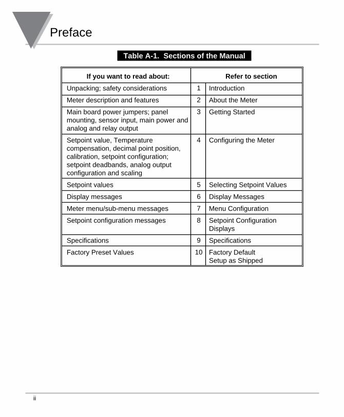
Table A-1. Sections of the Manual
If you want to read about:
Unpacking; safety considerations
Meter description and features
Main board power jumpers; panel mounting, sensor input, main power and analog and relay output
Setpoint value, Temperature compensation, decimal point position, calibration, setpoint configuration; setpoint deadbands, analog output configuration and scaling
Setpoint values
Display messages
Meter menu/sub-menu messages
Setpoint configuration messages
Specifications
Factory Preset Values
1
2
3
4
5
6
7
8
9
10
Refer to section
Introduction
About the Meter
Getting Started
Configuring the Meter
Selecting Setpoint Values
Display Messages
Menu Configuration
Setpoint Configuration Displays
Specifications
Factory Default Setup as Shipped
iii
Preface
Table of Contents
Section Page
SEC 1 INTRODUCTION . . . . . . . . . . . . . . . . . . . . . . . . . . . . . . . . . . . . . . . . . . . . 1 1.1 Unpacking . . . . . . . . . . . . . . . . . . . . . . . . . . . . . . . . . . . . . . . . . . . . . . . . . 1 1.2 Safety Considerations . . . . . . . . . . . . . . . . . . . . . . . . . . . . . . . . . . . . . . . . 2
SEC 2 ABOUT THE METER. . . . . . . . . . . . . . . . . . . . . . . . . . . . . . . . . . . . . . . . . 3 2.1 Description . . . . . . . . . . . . . . . . . . . . . . . . . . . . . . . . . . . . . . . . . . . . . . . . . 3 2.2 Features . . . . . . . . . . . . . . . . . . . . . . . . . . . . . . . . . . . . . . . . . . . . . . . . . . . 3 2.3 Available Accessories . . . . . . . . . . . . . . . . . . . . . . . . . . . . . . . . . . . . . . . . 4 2.4 Front of the Meter . . . . . . . . . . . . . . . . . . . . . . . . . . . . . . . . . . . . . . . . . . . 5 2.4.1 Meter Buttons . . . . . . . . . . . . . . . . . . . . . . . . . . . . . . . . . . . . . . . . . . . . . . . 6 2.5 Front Panel Button Lockout . . . . . . . . . . . . . . . . . . . . . . . . . . . . . . . . . . . . 8 2.5.1 Jumper Lock Out . . . . . . . . . . . . . . . . . . . . . . . . . . . . . . . . . . . . . . . . . . . . 8 2.5.2 Push Button Lock Out . . . . . . . . . . . . . . . . . . . . . . . . . . . . . . . . . . . . . . . . 8 2.6 Back of Meter . . . . . . . . . . . . . . . . . . . . . . . . . . . . . . . . . . . . . . . . . . . . . . . 9 2.7 Disassembly . . . . . . . . . . . . . . . . . . . . . . . . . . . . . . . . . . . . . . . . . . . . . . . 11
SEC 3 GETTING STARTED . . . . . . . . . . . . . . . . . . . . . . . . . . . . . . . . . . . . . . . . 12 3.1 Rating/Product Label . . . . . . . . . . . . . . . . . . . . . . . . . . . . . . . . . . . . . . . . 12 3.2 Main Board Power Jumpers . . . . . . . . . . . . . . . . . . . . . . . . . . . . . . . . . . . 12 3.3 Main Board Jumpers . . . . . . . . . . . . . . . . . . . . . . . . . . . . . . . . . . . . . . . . 13 3.4 Panel Mounting . . . . . . . . . . . . . . . . . . . . . . . . . . . . . . . . . . . . . . . . . . . . 15 3.5 Connecting Sensor Inputs . . . . . . . . . . . . . . . . . . . . . . . . . . . . . . . . . . . . 16 3.6 Connecting Main Power . . . . . . . . . . . . . . . . . . . . . . . . . . . . . . . . . . . . . . 17 3.7 Connecting Analog and Relay Outputs . . . . . . . . . . . . . . . . . . . . . . . . . . 18
SEC 4 CONFIGURING THE METER . . . . . . . . . . . . . . . . . . . . . . . . . . . . . . . . . 20 4.0 Specifying Input Type (INPT) pH/ORP Controllers Only . . . . . . . . . . . . . 20 4.1 Selecting the Temperature Compensation Mode (A.T.C.) . . . . . . . . . . . 20 4.2 Selecting a Decimal Point Position (DEC.P) . . . . . . . . . . . . . . . . . . . . . . 21 4.3 Using Reading Configuration (RD.CF) . . . . . . . . . . . . . . . . . . . . . . . . . . . 22 4.4 Performing Two-Point Calibration (CAL.2) . . . . . . . . . . . . . . . . . . . . . . . . 23 4.5 Performing Three-Point Calibration (CAL.3) . . . . . . . . . . . . . . . . . . . . . . 24
Preface
iv
Table of Contents
Section Page
4.6 Using Setpoint 1 Configurations (S1.CF) . . . . . . . . . . . . . . . . . . . . . . . . . 25 4.6.1 Setting Setpoint 1’s Active Band . . . . . . . . . . . . . . . . . . . . . . . . . . . . . . . 25 4.6.2 Selecting if Setpoint 1 is Latched or Unlatched . . . . . . . . . . . . . . . . . . . . 25 4.6.3 Selecting Setpoint 1 (for pH/ORP Controllers only) . . . . . . . . . . . . . . . . . 25 4.7 Using Setpoint 2 Configuration (S2.CF) . . . . . . . . . . . . . . . . . . . . . . . . . . 26 4.7.1 Setting Setpoint 2’s Active Band . . . . . . . . . . . . . . . . . . . . . . . . . . . . . . . 26 4.7.2 Selecting if Setpoint 2 is Latched or Unlatched . . . . . . . . . . . . . . . . . . . . 26 4.7.3 Selecting Setpoint 2 (for pH/ORP Controllers only) . . . . . . . . . . . . . . . . . 26 4.8 Setting the Setpoint 1 Deadband (S1.DB) . . . . . . . . . . . . . . . . . . . . . . . . 27 4.9 Setting the Setpoint 2 Deadband (S2.DB) . . . . . . . . . . . . . . . . . . . . . . . . 27 4.10 Using Output Configuration (OT.CF) . . . . . . . . . . . . . . . . . . . . . . . . . . . . 29 4.10.1 Enabling or Disabling the Analog Output . . . . . . . . . . . . . . . . . . . . . . . . . 29 4.10.2 Selecting Analog Output as Current or Voltage . . . . . . . . . . . . . . . . . . . . 29 4.10.3 Selecting Analog Output as pH or ORP (for pH/ORP Controllers only) . . 30 4.11 Configuring Temperature (C or F-TEMP) . . . . . . . . . . . . . . . . . . . . . . . . 31 4.12 Using Output Scale and Offset (OT.S.O) . . . . . . . . . . . . . . . . . . . . . . . . . 32 4.12.1 Example for Output Scale and Offset . . . . . . . . . . . . . . . . . . . . . . . . . . . 34
SEC 5 SELECTING SETPOINT VALUES . . . . . . . . . . . . . . . . . . . . . . . . . . . . . 35
SEC 6 DISPLAY MESSAGES . . . . . . . . . . . . . . . . . . . . . . . . . . . . . . . . . . . . . . 36
SEC 7 MENU CONFIGURATION DISPLAYS . . . . . . . . . . . . . . . . . . . . . . . . . . 37
SEC 8 SETPOINT CONFIGURATION DISPLAYS . . . . . . . . . . . . . . . . . . . . . . . 40
SEC 9 SPECIFICATIONS . . . . . . . . . . . . . . . . . . . . . . . . . . . . . . . . . . . . . . . . . . 41
SEC 10 FACTORY PRESET VALUES . . . . . . . . . . . . . . . . . . . . . . . . . . . . . . . . 45
CE APPROVAL SECTION . . . . . . . . . . . . . . . . . . . . . . . . . . . . . . . . . . . . . . . . . . . . . 46
v
Preface
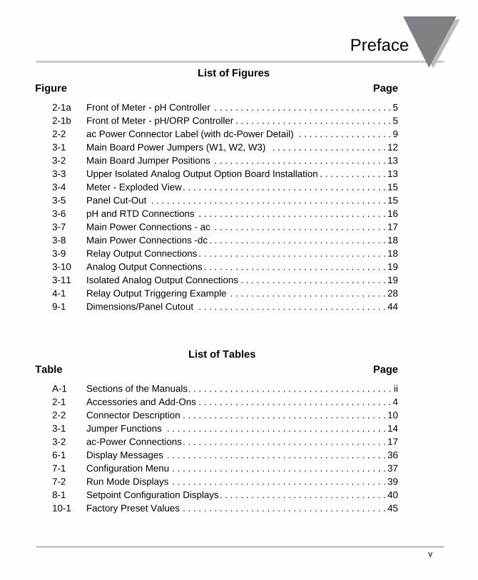
List of Figures
Figure Page
2-1a Front of Meter - pH Controller . . . . . . . . . . . . . . . . . . . . . . . . . . . . . . . . . . 5 2-1b Front of Meter - pH/ORP Controller . . . . . . . . . . . . . . . . . . . . . . . . . . . . . . 5 2-2 ac Power Connector Label (with dc-Power Detail) . . . . . . . . . . . . . . . . . . 9 3-1 Main Board Power Jumpers (W1, W2, W3) . . . . . . . . . . . . . . . . . . . . . . 12 3-2 Main Board Jumper Positions . . . . . . . . . . . . . . . . . . . . . . . . . . . . . . . . . 13 3-3 Upper Isolated Analog Output Option Board Installation . . . . . . . . . . . . . 13 3-4 Meter - Exploded View . . . . . . . . . . . . . . . . . . . . . . . . . . . . . . . . . . . . . . . 15 3-5 Panel Cut-Out . . . . . . . . . . . . . . . . . . . . . . . . . . . . . . . . . . . . . . . . . . . . . 15 3-6 pH and RTD Connections . . . . . . . . . . . . . . . . . . . . . . . . . . . . . . . . . . . . 16 3-7 Main Power Connections - ac . . . . . . . . . . . . . . . . . . . . . . . . . . . . . . . . . 17 3-8 Main Power Connections -dc . . . . . . . . . . . . . . . . . . . . . . . . . . . . . . . . . . 18 3-9 Relay Output Connections . . . . . . . . . . . . . . . . . . . . . . . . . . . . . . . . . . . . 18 3-10 Analog Output Connections . . . . . . . . . . . . . . . . . . . . . . . . . . . . . . . . . . . 19 3-11 Isolated Analog Output Connections . . . . . . . . . . . . . . . . . . . . . . . . . . . . 19 4-1 Relay Output Triggering Example . . . . . . . . . . . . . . . . . . . . . . . . . . . . . . 28 9-1 Dimensions/Panel Cutout . . . . . . . . . . . . . . . . . . . . . . . . . . . . . . . . . . . . 44
List of Tables
Table Page
A-1 Sections of the Manuals . . . . . . . . . . . . . . . . . . . . . . . . . . . . . . . . . . . . . . . ii 2-1 Accessories and Add-Ons . . . . . . . . . . . . . . . . . . . . . . . . . . . . . . . . . . . . . 4 2-2 Connector Description . . . . . . . . . . . . . . . . . . . . . . . . . . . . . . . . . . . . . . . 10 3-1 Jumper Functions . . . . . . . . . . . . . . . . . . . . . . . . . . . . . . . . . . . . . . . . . . 14 3-2 ac-Power Connections . . . . . . . . . . . . . . . . . . . . . . . . . . . . . . . . . . . . . . . 17 6-1 Display Messages . . . . . . . . . . . . . . . . . . . . . . . . . . . . . . . . . . . . . . . . . . 36 7-1 Configuration Menu . . . . . . . . . . . . . . . . . . . . . . . . . . . . . . . . . . . . . . . . . 37 7-2 Run Mode Displays . . . . . . . . . . . . . . . . . . . . . . . . . . . . . . . . . . . . . . . . . 39 8-1 Setpoint Configuration Displays . . . . . . . . . . . . . . . . . . . . . . . . . . . . . . . . 40 10-1 Factory Preset Values . . . . . . . . . . . . . . . . . . . . . . . . . . . . . . . . . . . . . . . 45
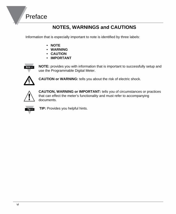
NOTES, WARNINGS and CAUTIONS
Information that is especially important to note is identified by three labels:
• NOTE • WARNING • CAUTION • IMPORTANT
NOTE: provides you with information that is important to successfully setup and use the Programmable Digital Meter.
CAUTION or WARNING: tells you about the risk of electric shock.
CAUTION, WARNING or IMPORTANT: tells you of circumstances or practices that can effect the meter’s functionality and must refer to accompanying documents.
TIP: Provides you helpful hints.
Preface
vi
1
Introduction 1SECTION 1. INTRODUCTION
1.1 UNPACKING
Remove the Packing List and verify that all equipment has been received. If there are any questions about the shipment, use the phone number for the Customer Service Department nearest you.
Upon receipt of shipment, inspect the container and equipment for any signs of damage. Take particular note of any evidence of rough handling in transit. Immediately report any damage to the shipping agent.
The carrier will not honor any claims unless all shipping material is saved for their examination. After examining and removing contents, save packing material and carton in the event reshipment is necessary.
Verify that you receive the following items in the shipping box:
QTY DESCRIPTION
1 Programmable Digital Meter indicator/controller with all applicable connectors attached.
1 Owner’s Manual
1 Set Mounting brackets
If you ordered any of the available options (except the “BL” blank Lens option), they will be shipped in a separate container to avoid any damage to your indicator/controller.
For first-time users: Refer to the QuickStart Manual for basic operation and set-up instructions.
1 Introduction
2
1.2 SAFETY CONSIDERATIONS
This device is marked with the international caution symbol. It is important to read this manual before installing or commissioning this device as it contains important information relating to Safety and EMC (Electromagnetic Compatibility).
This instrument is a panel mount device protected in accordance with 2014/35/EU, electrical safety requirements for electrical equipment for measurement, control and laboratory. Installation of this instrument should be done by qualified personnel. In order to ensure safe operation, the following instructions should be followed.
This instrument has no power-on switch. An external switch or circuit-breaker shall be included in the building installation as a disconnecting device. It shall be marked to indicate this function, and it shall be in close proximity to the equipment within easy reach of the operator. The switch or circuit-breaker shall not interrupt the Protective Conductor (Earth wire), and it shall meet the relevant requirements of IEC 947–1 and IEC 947-3 (International Electrotechnical Commission). The switch shall not be incorporated in the main supply cord.
Furthermore, to provide protection against excessive energy being drawn from the main supply in case of a fault in the equipment, an overcurrent protection device shall be installed.
• Do not exceed voltage rating on the label located on the top of the instrumenthousing.
• Always disconnect power before changing signal and power connections.• Do not use this instrument on a work bench without its case for safety reasons.• Do not operate this instrument in flammable or explosive atmospheres.• Do not expose this instrument to rain or moisture.• Unit mounting should allow for adequate ventilation to ensure instrument does not
exceed operating temperature rating.• Use electrical wires with adequate size to handle mechanical strain and power
requirements. Install without exposing bare wire outside the connector to minimizeelectrical shock hazards.
EMC Considerations• Whenever EMC is an issue, always use shielded cables.• Never run signal and power wires in the same conduit.• Use signal wire connections with twisted-pair cables.• Install Ferrite Bead(s) on signal wires close to the instrument if EMC problems
persist.
Failure to follow all instructions and warnings may result in injury!
Note �
3
About The Meter 2SECTION 2. ABOUT THE METER
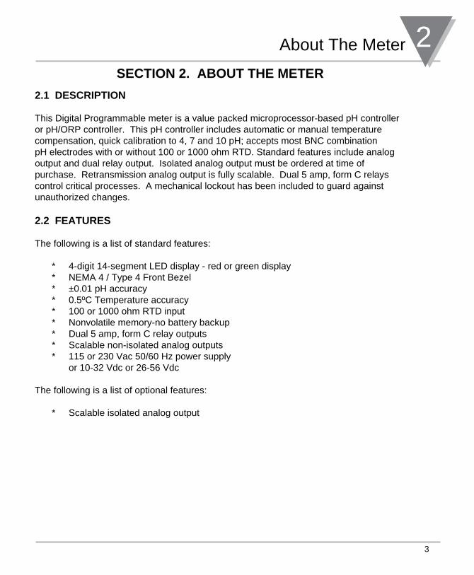
2.1 DESCRIPTION
This Digital Programmable meter is a value packed microprocessor-based pH controller or pH/ORP controller. This pH controller includes automatic or manual temperature compensation, quick calibration to 4, 7 and 10 pH; accepts most BNC combination pH electrodes with or without 100 or 1000 ohm RTD. Standard features include analog output and dual relay output. Isolated analog output must be ordered at time of purchase. Retransmission analog output is fully scalable. Dual 5 amp, form C relays control critical processes. A mechanical lockout has been included to guard against unauthorized changes.
2.2 FEATURES
The following is a list of standard features:
* 4-digit 14-segment LED display - red or green display* NEMA 4 / Type 4 Front Bezel* ±0.01 pH accuracy* 0.5ºC Temperature accuracy* 100 or 1000 ohm RTD input* Nonvolatile memory-no battery backup* Dual 5 amp, form C relay outputs* Scalable non-isolated analog outputs* 115 or 230 Vac 50/60 Hz power supply or 10-32 Vdc or 26-56 Vdc
The following is a list of optional features:
* Scalable isolated analog output
2 About The Meter
4
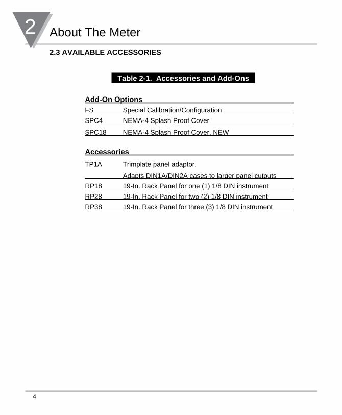
2.3 AVAILABLE ACCESSORIES
Table 2-1. Accessories and Add-Ons
Add-On Options FS Special Calibration/Configuration
SPC4 NEMA-4 Splash Proof Cover
SPC18 NEMA-4 Splash Proof Cover, NEW
Accessories
TP1A Trimplate panel adaptor.
Adapts DIN1A/DIN2A cases to larger panel cutouts
RP18 19-In. Rack Panel for one (1) 1/8 DIN instrument
RP28 19-In. Rack Panel for two (2) 1/8 DIN instrument
RP38 19-In. Rack Panel for three (3) 1/8 DIN instrument
5
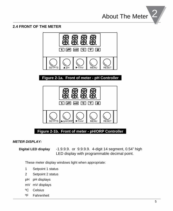
About The Meter 22.4 FRONT OF THE METER
SETPTS T/mV MENU RESET/pH
Figure 2-1a. Front of meter - pH Controller
SETPTS T/mV MENU RESET/pH/ORP
Figure 2-1b. Front of meter - pH/ORP Controller
meteR DIsplay:
Digital LED display -1.9.9.9. or 9.9.9.9. 4-digit 14 segment, 0.54” high LED display with programmable decimal point.
These meter display windows light when appropriate:
1 Setpoint 1 status
2 Setpoint 2 status
pH pH displays
mV mV displays
ºC Celsius
ºF Fahrenheit
2 About The Meter
6
2.4.1 METER BUTTONS
SETPTS Button
In the run mode, this button will sequentially recall the previous setpoint settings. As necessary, use the /pH and /mV buttons to alter these settings, then press the SETPTS button to store new values.
Unless you press the SETPTS, /pH, or /mV button within 20 seconds, the meter will scroll to setpoint 2 and then to the run mode.
/pH Button (for pH Controller)
In the run mode, this button will view pH value.
In the configuration mode, press this button to change the value of the flashing digit shown on the display and/or toggle between menu choices, such as “R.2=F” or “R.2=C” on RD.CF menu. When configuring your setpoint values, press the /pH button to advance the flashing digit’s value from 0 to 9 by 1.
/pH/ORP Button (for pH/ORP Controller)
In the run mode, this button will view pH value.
If you have a pH/ORP Controller: throughout this manual’s text, the /pH/ORP button is referenced as the /pH button.
To toggle between the pH and ORP values while in the “Run Mode” (Normal Operation). Use this button also to change the value of the digits while in the “Setpoint” and “Menu” (Configuration) Modes.
T/mV Button (for pH Controller)
In the run mode press the T/mV button to recall the mV value of your input signal. Press the T/mV button a second time to recall the temperature value of your input. In the configuration mode, press this button to scroll to the next digit.
T/mV Button (for pH/ORP Controller)
To view temperature while in the “Run Mode” (Normal Operation). Use this button also to select the digit’s position while in the “Setpoint” and “Menu” (Configuration) Modes.
7
About The Meter 22.4.1 METER BUTTONS (Continued)
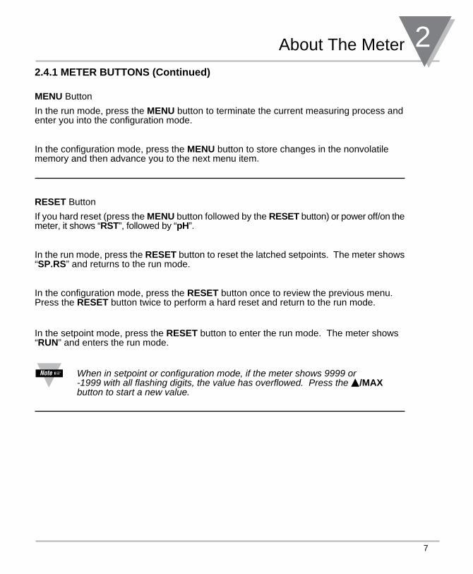
MENU Button
In the run mode, press the MENU button to terminate the current measuring process and enter you into the configuration mode.
In the configuration mode, press the MENU button to store changes in the nonvolatile memory and then advance you to the next menu item.
RESET Button
If you hard reset (press the MENU button followed by the RESET button) or power off/on the meter, it shows “RST”, followed by “pH”.
In the run mode, press the RESET button to reset the latched setpoints. The meter shows “SP.RS” and returns to the run mode.
In the configuration mode, press the RESET button once to review the previous menu. Press the RESET button twice to perform a hard reset and return to the run mode.
In the setpoint mode, press the RESET button to enter the run mode. The meter shows “RUN” and enters the run mode.
When in setpoint or configuration mode, if the meter shows 9999 or -1999 with all flashing digits, the value has overflowed. Press the /MAX button to start a new value.
2 About The Meter
8
2.5 FRONT-PANEL BUTTON LOCK OUT (For Security Purposes)
2.5.1 Jumper Lock Out
To lock all front-panel buttons, remove the S3-A jumper (refer to Figure 3-2). To lock the MENU button only, verify that the S3-B jumper is removed, then install the S3-A and S3-E jumpers (refer to Table 3-1). If you press the MENU button, the meter shows “LOCK” and returns to the run mode.
2.5.2 Push Button Lock OutTo lock the RESET, MENU and SETPTS buttons only, verify that the S3-A jumper is installed and the S3-E jumper is not installed, then follow these steps:
In the run mode -
1. Press and hold down the RESET button. The meter shows “SP.RS” or “RUN”. Do not release the RESET button.
2. Press the MENU button and hold the RESET button down (3-5 seconds) until the meter shows “LOCK”.
3. Release both buttons.
To unlock the RESET, MENU and SETPTS buttons, follow these steps:
1. Press and hold down the RESET button. The meter shows “LOCK”. Do not release the RESET button.
2. Press the MENU button and hold the RESET button down (3-5 seconds) until the meter shows “UN.LK”.
3. Release both buttons.
9
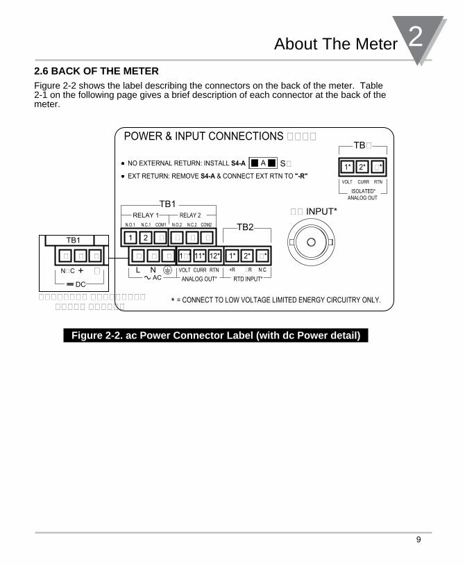
About The Meter 22.6 BACK OF THE METERFigure 2-2 shows the label describing the connectors on the back of the meter. Table 2-1 on the following page gives a brief description of each connector at the back of the meter.
+R
RTD INPUT*ANALOG OUT*
TB1RELAY 1 RELAY 2
ISOLATED*
* = CONNECT TO LOW VOLTAGE LIMITED ENERGY CIRCUITRY ONLY.
ANALOG OUT
A
EXT RETURN: REMOVE S4-A & CONNECT EXT RTN TO "-R"
NO EXTERNAL RETURN: INSTALL S4-A
TB2
�� INPUT*
RTNVOLT CURR
TB�POWER & INPUT CONNECTIONS ����
S�
DC
TB1
AC
���
N�C + �
N.C.2N.C.1N.O.1 COM1 COM2N.O.2
VOLT RTNCURR N�C�RL N
�������� �������������� ������
�21 ���
��� 12*11*1�* �*2*1*
�*2*1*
Figure 2-2. ac Power Connector Label (with dc Power detail)
2 About The Meter
10
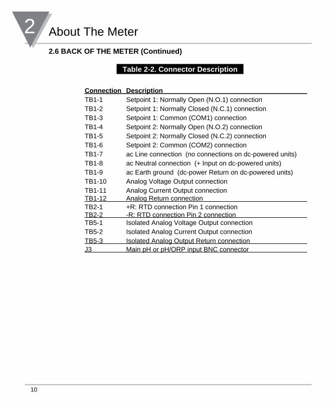
2.6 BACK OF THE METER (Continued)
Table 2-2. Connector Description
Connection Description TB1-1 Setpoint 1: Normally Open (N.O.1) connectionTB1-2 Setpoint 1: Normally Closed (N.C.1) connectionTB1-3 Setpoint 1: Common (COM1) connectionTB1-4 Setpoint 2: Normally Open (N.O.2) connectionTB1-5 Setpoint 2: Normally Closed (N.C.2) connectionTB1-6 Setpoint 2: Common (COM2) connectionTB1-7 ac Line connection (no connections on dc-powered units)TB1-8 ac Neutral connection (+ Input on dc-powered units)TB1-9 ac Earth ground (dc-power Return on dc-powered units)TB1-10 Analog Voltage Output connectionTB1-11 Analog Current Output connectionTB1-12 Analog Return connection TB2-1 +R: RTD connection Pin 1 connectionTB2-2 -R: RTD connection Pin 2 connection TB5-1 Isolated Analog Voltage Output connectionTB5-2 Isolated Analog Current Output connectionTB5-3 Isolated Analog Output Return connection J3 Main pH or pH/ORP input BNC connector
11
About The Meter 22.7 DISASSEMBLYYou may need to open up the meter for one of the following reasons:
• To check or change the 115 or 230 Vac power jumpers.
• To install or remove jumpers on the main board.
Disconnect the power supply before proceeding.
To remove and access the main board, follow these steps:
• Disconnect the main power from the meter.
• Remove the back case cover.
• Lift the back of the main board upwards and let it slide out of the case.

3 Getting Started
12
SECTION 3. GETTING STARTED
Caution: The meter has no power-on switch, so it will be in operation as soon you apply power.
If you power off/on the meter, or perform a hard reset (press the RESET button twice), the meter shows “RST”, followed by “PH”.
3.1 RATING/PRODUCT LABEL This label is located on top of the meter housing (refer to Figure 3-4).
3.2 MAIN BOARD POWER JUMPERS (refer to Figure 3-1) Important: If you want to change the Factory preset jumpers, do the following steps; otherwise go to section 3.3.
Disconnect the power from the unit before proceeding.
1. Remove the main board from the case. Refer to Section 2.7.
2. Locate the solder jumpers W1, W2, and W3 (located near the edge of the main board alongside the transformer).
3. If your power requirement is 115 V ac, solder jumpers W1 and W3 should be wired, but jumper W2 should not. If your power requirement is 230 V ac, solder jumper W2 should be wired, but jumpers W1 and W3 should not.
Figure 3-1 shows the location of solder jumpers W1 through W3.
DIS
PLA
Y B
OA
RD
TRANSFORMERW3 W1
W2
115V ac
230V ac
W3 W2 W1
Figure 3.1 Main Board Power Jumpers
13
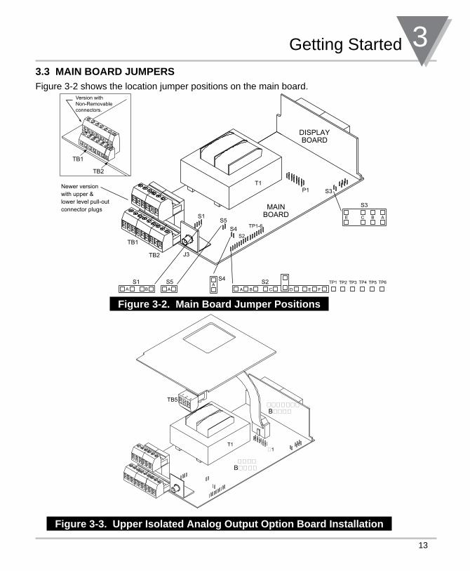
Getting Started 33.3 MAIN BOARD JUMPERSFigure 3-2 shows the location jumper positions on the main board.
Figure 3-2. Main Board Jumper Positions
12
3TB5
����B����
�������B����
�1T1
Figure 3-3. Upper Isolated Analog Output Option Board Installation
S3
S2AS4
A
S5S1
E BC A
B CA D E FA B
S2S4
S5
S3P1T1
DISPLAYBOARD
MAINBOARDS1
Newer versionwith upper &lower level pull-outconnector plugs
TP1-6
TP1 TP2 TP3 TP4 TP5 TP6
TB1
TB2
Version with Non-Removable connectors.
TB1
TB2 J3

3 Getting Started
14
3.3 MAIN BOARD JUMPERS (Continued) S1 jumper is for factory use only. Do not install or remove them.
S2 jumper allows you to use the meter without ATC.
S3 jumpers are used for the following: (Refer to Figure 3-2)* To enable or disable the front panel push-buttons* To allow for an extremely low resistance load for analog output* To disable the MENU button* To perform calibration procedure
S4 jumpers allow you to use electrode solution ground wire or internal ground for measurement purposes.
S5 jumpers allow you to use 100 ohm or 1000 ohm RTD sensors.
S6 jumper: Not used
This will affect will affect the way the relay outputs work depending on whether they are set for active above or active below.
Table 3-1. Jumper Functions
Jumper Description
S2-D Install if Temperature sensor is not used.
S3-A Install to enable front panel push-buttons.Remove to disable all front panel push-buttons.
S3-B Removed. Install for meter calibration.
S3-C Normally removed. Install for analog output when load is less than 1 K Ω impedance. Care should be taken when installing this jump-er.
S3-D Removed. Not used.
S3-E If installed without S3-B, the MENU button locks out. If you press the MENU button, the meter shows “LOCK”.
S4-A Install when using internal ground. Remove when using electrode solution ground wire.
S5-A Install for 100 ohm RTD sensor. Remove for 1000 ohm RTD sensor.
15
Getting Started 33.4 PANEL MOUNTING
"NEW" STYLEMOUNTINGBRACKET
FRONT BEZEL
CASE
REAR COVER
(REMOVED)
PANELCUT-OUT
"OLDER" STYLEMOUNTING
BRACKET 2 PCSGASKET
PRODUCTLABEL
CONNECTORLABEL
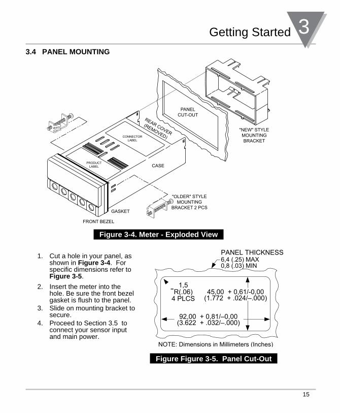
Figure 3-4. Meter - Exploded View
1. Cut a hole in your panel, as shown in Figure 3-4. For specific dimensions refer to Figure 3-5.
2. Insert the meter into the hole. Be sure the front bezel gasket is flush to the panel.
3. Slide on mounting bracket to secure.
4. Proceed to Section 3.5 to connect your sensor input and main power.
Figure Figure 3-5. Panel Cut-Out
45,00 + 0,61/-0,00(1.772 + .024/–.000)
92,00 + 0,81/–0,00(3.622 + .032/–.000)
PANEL THICKNESS
1,5R(.06)
4 PLCS
6,4 (.25) MAX0,8 (.03) MIN
NOTE: Dimensions in Millimeters (Inches)
3 Getting Started
16
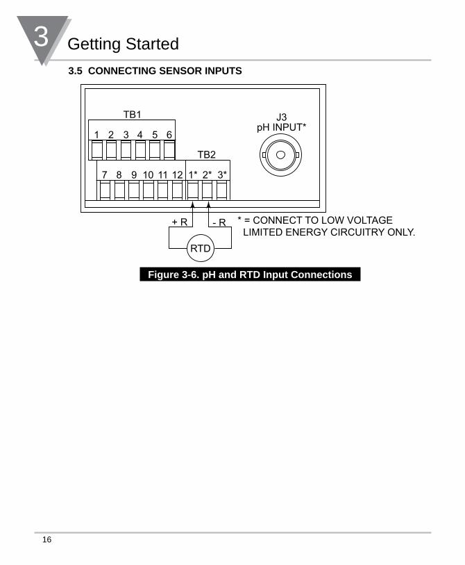
3.5 CONNECTING SENSOR INPUTS
+ R - R
TB1
1 2 3 4 5 6
J3pH INPUT*
* = CONNECT TO LOW VOLTAGE LIMITED ENERGY CIRCUITRY ONLY.
7 8 9 10 1* 2* 3*11 12
TB2
RTD
Figure 3-6. pH and RTD Input Connections
17
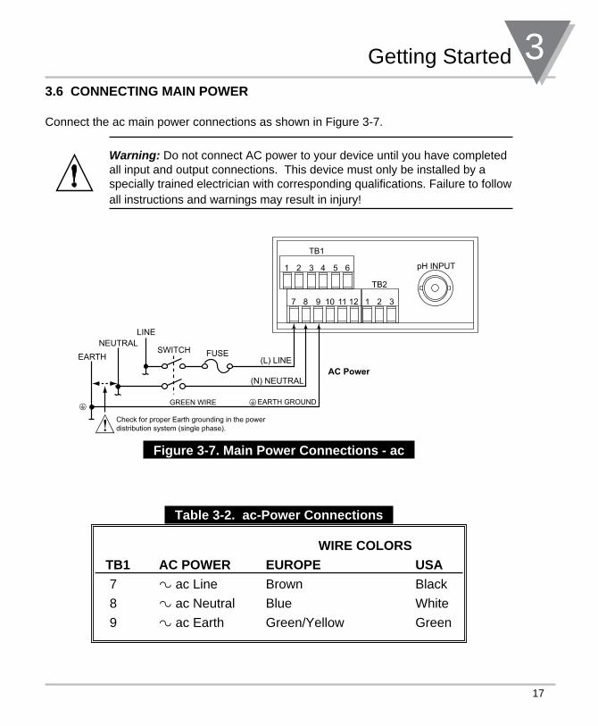
Getting Started 33.6 CONNECTING MAIN POWER
Connect the ac main power connections as shown in Figure 3-7.
Warning: Do not connect AC power to your device until you have completed all input and output connections. This device must only be installed by a specially trained electrician with corresponding qualifications. Failure to follow all instructions and warnings may result in injury!
TB1
TB2
1 2 3 4 5 6
7 8 9 10 1 2 311 12
FUSE
EARTH GROUNDGREEN WIRE
� AC Power
Check for proper Earth grounding in the power distribution system (single phase).
SWITCH
LINENEUTRAL
EARTH (L) LINE
(N) NEUTRAL
pH INPUT
Figure 3-7. Main Power Connections - ac
Table 3-2. ac-Power Connections
WIRE COLORS
TB1 AC POWER EUROPE USA
7 ~ ac Line Brown Black
8 ~ ac Neutral Blue White
9 ~ ac Earth Green/Yellow Green
3 Getting Started
18
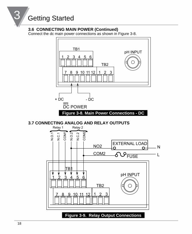
3.6 CONNECTING MAIN POWER (Continued)Connect the dc main power connections as shown in Figure 3-8.
+ DC - DC
DC POWER
TB1
1 2 3 4 5 6pH INPUT
7 8 9 10 1 2 311 12
TB2
Figure 3-8. Main Power Connections - DC
3.7 CONNECTING ANALOG AND RELAY OUTPUTS
Relay 1 Relay 2
N.O
.1
N.C
.1
CO
M1
N.O
.2
N.C
.2
CO
M2} }
TB1
1 2 3 4 5 6
7 8 9 10 11 12
TB2
1 2 3
EXTERNAL LOADN
LFUSE
NO2
COM2
pH INPUT
y Figure 3-9. Relay Output Connections
19
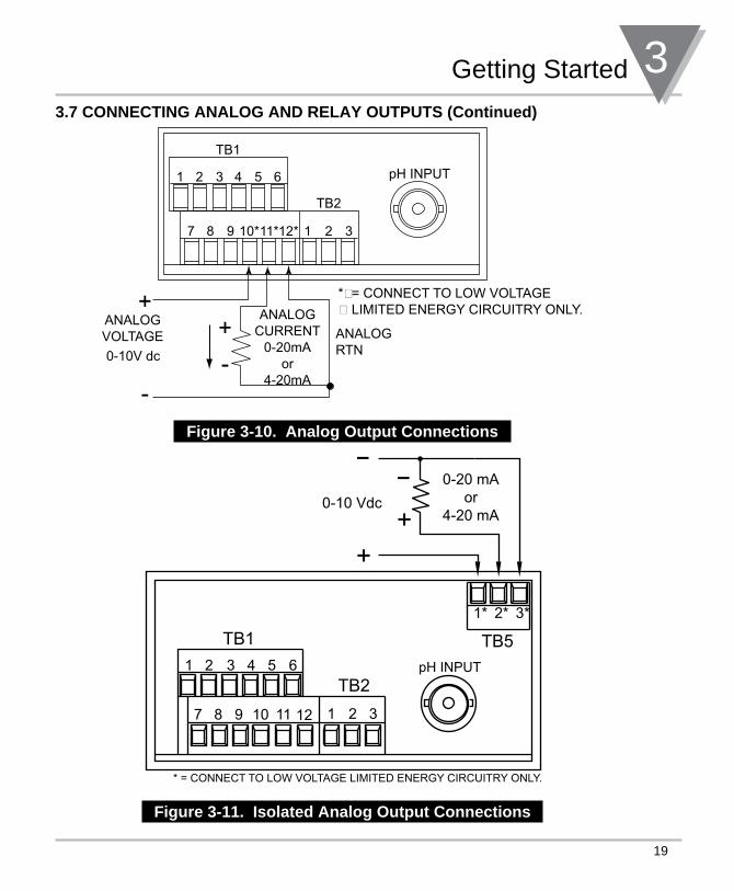
Getting Started 33.7 CONNECTING ANALOG AND RELAY OUTPUTS (Continued)
TB1
TB2
1 2 3 4 5 6
7 8 9 10* 1 2 311*12*
pH INPUT
*�= CONNECT TO LOW VOLTAGE� LIMITED ENERGY CIRCUITRY ONLY.
Figure 3-10. Analog Output Connections
i
1* 2* 3*
TB5TB1
TB21 2 3 4
1 2 3
5 6
7 8 9 10 11 12
pH INPUT
* = CONNECT TO LOW VOLTAGE LIMITED ENERGY CIRCUITRY ONLY.
Figure 3-11. Isolated Analog Output Connections
4 Configuring The Meter
2020
SECTION 4. CONFIGURING THE METER • Refer to Table 7-1 for a summary list of menu configuration.
• Factory defaults are in bold and italics.
• The Unit of Measurement for setpoints, deadbands, and read 1/read 2 (Output Scale and Offset) is all in Millivolts. The decimal point will always be at position 1 (for right position) for these items.
• The corresponding Unit of Measurement (pH or mV) will flash when viewing values.
4.0 SPECIFYING INPUT TYPE (“INPT”) (for pH/ORP controllers ony)
Under this menu there are two choices:
pH: The meter acts as a typical pH meter
ORP: The meter acts as a ORP/pH meter
1. Press the T/mV button once. The current input type is displayed.
2. Press the /pH/ORP button to select pH or ORP. When the desired choice is displayed, press the MENU button. This enters the value into the microprocessor and “STRD” will momentarily flash on the display. The next menu item, “A.T.C.”, will automatically appear on the display.
4.1 SELECTING THE TEMPERATURE COMPENSATION MODE (“A.T.C.”)To select your appropriate compensation type, follow these steps:
1. Press the MENU button. The meter shows “A.T.C”.
2. Press the T/mV button. The meter shows one of the following:
• “metR” meter utilizes the RTD input for automatic temperature compensation. (Default)
• “OFF” meter utilizes a constant 25ºC for temperature compensation.
• “MANU” meter utilizes a manually entered value for temperature compensation.
3. Press the /pH button to scroll through available choices.
4. Press the MENU button to store your choice. The meter momentarily shows “STRD”, followed by “DEC.P” (Decimal Point).
21
Configuring The Meter 44.2 SELECTING A DECIMAL POINT POSITION (“DEC.P”) To select a decimal point display position, follow these steps:
1. Press the MENU button until the meter shows “DEC.P”.
2. Press the T/mV button. The meter shows one of the following:
• “FFF.F” (Default)
• “FFFF.”
• “FF.FF”
3. Press the /pH button to scroll through available choices.
4. Press the MENU button to store your choice. The meter momentarily shows “STRD”, followed by “RG.CF” (Reading Configuration).
4 Configuring The Meter
22
4.3 USING READING CONFIGURATION (“RD.CF”)
To select the calibration mode and units of measurement, follow these steps:
1. Press the MENU button until the meter shows “RD.CF”.
2. Press the T/mV button. The meter shows one of the following:
• “R.1=2” For the two point buffer solution calibration (either 4 and 7, or 7 and 10 buffer solutions are used).
• “R.1=3” For three point buffer solution calibration (4, 7, or 7 and 10 buffer solutions are used). (Default)
3. Press the /pH button to scroll through available choices.
4. Press the T/mV button to advance to the next submenu. The meter shows one of the following:
• “R.2=C” The displayed temperature in degrees Celsius (Default)
• “R.2=F” The displayed temperature in degrees Fahrenheit.
5. Press the /pH button to scroll through available choices.
6. Press the MENU button to store your choice. The meter momentarily shows “STRD”, followed by “CAL.2” or “CAL.3”.
Refer to step 4.1, during this step a temperature compensation type was chosen. If “OFF” was chosen then proceed to the “CAL.2” or “CAL.3” menu. If “METR” was selected, connect the RTD sensor’s leads to the RTD input connector, and proceed to the “CAL.2” or “CAL.3” menu. If “MANU” was selected, press the MENU button until the “TEMP” menu displayed. (step 4.11 - Configuring Temperature).
23
Configuring The Meter 44.4 PERFORMING TWO-POINT CALIBRATION (“CAL.2”)
Only buffer solutions of 4, 7 and 10 are acceptable. IF the buffer value is not accepted, the meter will display a flashing “PH.ER“.
Two-point calibration should be performed with two combinations of two buffer solutions (4 and 7, or 7 and 10).
1. Place your electrode into a buffer solution.
2. Press the MENU button until the meter shows “CAL.2”
3. Press the T/mV button. The meter shows “IN 1” (Input 1)
4. Press the T/mV button again. The meter shows the previous value of “IN 1”.
5. Press the T/mV button again. The meter shows the actual buffer solution’s pH value.
Please allow enough time for the electrode to settle before processing.
6. Press the MENU button to store the “IN 1” value. The meter momentarily shows an “OK” with buffer value (“OK.4”, “OK.7”, or “OK.10”), followed by “IN 2” (Input 2)
7. Rinse the electrode with distilled water and place it into the second buffer solution.
8. Press the T/mV button. The meter shows the previous value of “IN 2”
9. Press the T/mV button again. The meter shows the actual buffer solution’s pH value.
Please allow enough time for the electrode to settle before processing.
10. Press the MENU button to store the “IN 1” value. The meter momentarily shows an “OK” with buffer value (“OK.4”, “OK.7”, or “OK.10”), then momentarily shows “STRD”, followed by “S1.CF” (Setpoint 1 Configuration).
4 Configuring The Meter
24
4.5 PERFORMING THREE-POINT CALIBRATION (“CAL.3”)
Only buffer solutions of 4, 7 and 10 are acceptable. IF the buffer value is not accepted, the meter will display a flashing “PH.ER“.
1. Place your electrode into the pH buffer solution.
2. Press the MENU button until the meter shows “CAL.3”
3. Press the T/mV button. The meter shows “IN 1” (Input 1)
4. Press the T/mV button again. The meter shows the previous value of “IN 1”.
5. Press the T/mV button again. The meter shows the actual buffer solution’s pH value.
Please allow enough time for the electrode to settle before processing.
6. Press the MENU button to store the “IN 1” value. The meter momentarily shows an “OK.4”, followed by “IN 2” (Input 2)
7. Rinse the electrode with distilled water and place it into the pH 7 buffer solution.
8. Press the T/mV button. The meter shows the previous value of “IN 2”
9. Press the T/mV button again. The meter shows the actual buffer solution’s pH value.
Please allow enough time for the electrode to settle before processing.
10. Press the MENU button to store the “IN 2” value. The meter momentarily shows an “OK.7”, followed by “IN 3” (Input 3)
11. Rinse the electrode with distilled water and place it into the pH 10 buffer solution.
12. Press the T/mV button. The meter shows the previous value of “IN 3”
13. Press the T/mV button again. The meter shows the actual buffer solution’s pH value.
Please allow enough time for the electrode to settle before processing.
14. Press the MENU button to store the “IN 3” value. The meter momentarily shows an “OK.10”, then momentarily shows “STRD”, followed by “S1.CF” (Setpoint 1 Configuration).
25
Configuring The Meter 4
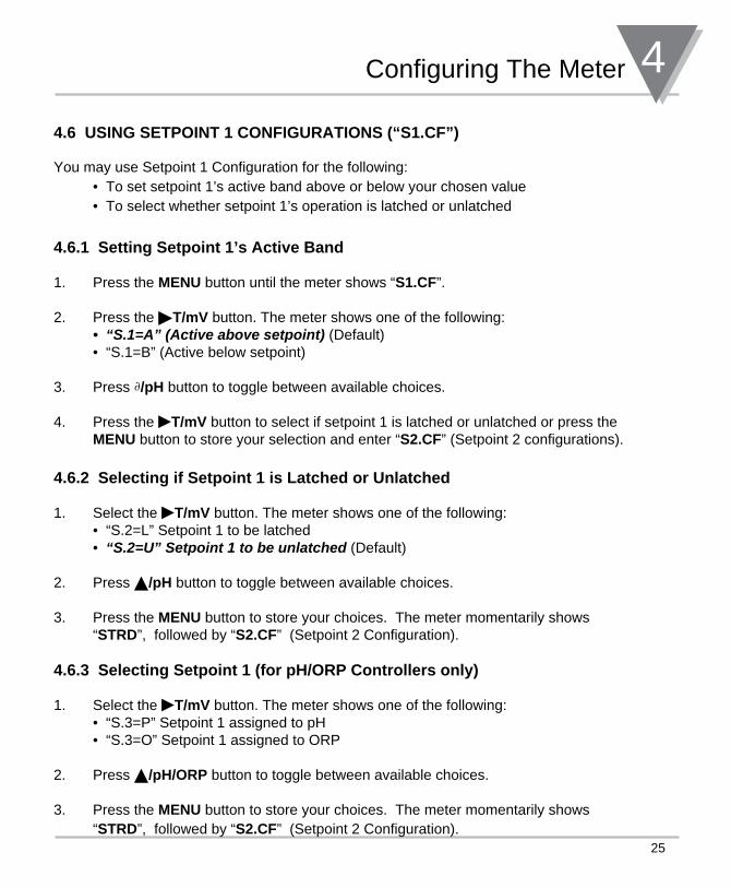
4.6 USING SETPOINT 1 CONFIGURATIONS (“S1.CF”)
You may use Setpoint 1 Configuration for the following: • To set setpoint 1’s active band above or below your chosen value • To select whether setpoint 1’s operation is latched or unlatched
4.6.1 Setting Setpoint 1’s Active Band
1. Press the MENU button until the meter shows “S1.CF”.
2. Press the T/mV button. The meter shows one of the following: • “s.1=a” (active above setpoint) (Default)
• “S.1=B” (Active below setpoint)
3. Press ∂/pH button to toggle between available choices.
4. Press the T/mV button to select if setpoint 1 is latched or unlatched or press the MENU button to store your selection and enter “S2.CF” (Setpoint 2 configurations).
4.6.2 Selecting if Setpoint 1 is Latched or Unlatched
1. Select the T/mV button. The meter shows one of the following: • “S.2=L” Setpoint 1 to be latched
• “s.2=U” setpoint 1 to be unlatched (Default)
2. Press /pH button to toggle between available choices.
3. Press the MENU button to store your choices. The meter momentarily shows “STRD”, followed by “S2.CF” (Setpoint 2 Configuration).
4.6.3 Selecting Setpoint 1 (for pH/ORP Controllers only)
1. Select the T/mV button. The meter shows one of the following: • “S.3=P” Setpoint 1 assigned to pH
• “S.3=O” Setpoint 1 assigned to ORP
2. Press /pH/ORP button to toggle between available choices.
3. Press the MENU button to store your choices. The meter momentarily shows “STRD”, followed by “S2.CF” (Setpoint 2 Configuration).
4 Configuring The Meter
26
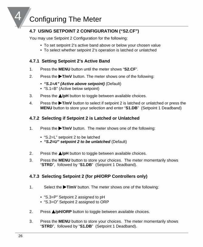
4.7 USING SETPOINT 2 CONFIGURATION (“S2.CF”)
You may use Setpoint 2 Configuration for the following:
• To set setpoint 2’s active band above or below your chosen value • To select whether setpoint 2’s operation is latched or unlatched
4.7.1 Setting Setpoint 2’s Active Band
1. Press the MENU button until the meter shows “S2.CF”.
2. Press the T/mV button. The meter shows one of the following:
• “s.1=a” (active above setpoint) (Default) • “S.1=B” (Active below setpoint)
3. Press the /pH button to toggle between available choices.
4. Press the T/mV button to select if setpoint 2 is latched or unlatched or press the MENU button to store your selection and enter “S1.DB” (Setpoint 1 Deadband)
4.7.2 Selecting if Setpoint 2 is Latched or Unlatched
1. Press the T/mV button. The meter shows one of the following:
• “S.2=L” setpoint 2 to be latched • “s.2=U” setpoint 2 to be unlatched (Default)
2. Press the /pH button to toggle between available choices.
3. Press the MENU button to store your choices. The meter momentarily shows “STRD”, followed by “S1.DB” (Setpoint 1 Deadband).
4.7.3 Selecting Setpoint 2 (for pH/ORP Controllers only)
1. Select the T/mV button. The meter shows one of the following:
• “S.3=P” Setpoint 2 assigned to pH • “S.3=O” Setpoint 2 assigned to ORP
2. Press /pH/ORP button to toggle between available choices.
3. Press the MENU button to store your choices. The meter momentarily shows “STRD”, followed by “S1.DB” (Setpoint 1 Deadband).
27
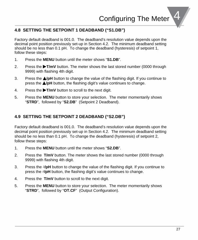
Configuring The Meter 44.8 SETTING THE SETPOINT 1 DEADBAND (“S1.DB”) Factory default deadband is 001.0. The deadband’s resolution value depends upon the decimal point position previously set-up in Section 4.2. The minimum deadband setting should be no less than 0.1 pH. To change the deadband (hysteresis) of setpoint 1, follow these steps:
1. Press the MENU button until the meter shows “S1.DB”.
2. Press the T/mV button. The meter shows the last stored number (0000 through 9999) with flashing 4th digit.
3. Press the /pH button to change the value of the flashing digit. If you continue to press the /pH button, the flashing digit’s value continues to change.
4. Press the T/mV button to scroll to the next digit.
5. Press the MENU button to store your selection. The meter momentarily shows “STRD”, followed by “S2.DB” (Setpoint 2 Deadband).
4.9 SETTING THE SETPOINT 2 DEADBAND (“S2.DB”) Factory default deadband is 001.0. The deadband’s resolution value depends upon the decimal point position previously set-up in Section 4.2. The minimum deadband setting should be no less than 0.1 pH. To change the deadband (hysteresis) of setpoint 2, follow these steps:
1. Press the MENU button until the meter shows “S2.DB”.
2. Press the ©T/mV button. The meter shows the last stored number (0000 through 9999) with flashing 4th digit.
3. Press the ∂/pH button to change the value of the flashing digit. If you continue to press the ∂/pH button, the flashing digit’s value continues to change.
4. Press the ©T/mV button to scroll to the next digit.
5. Press the MENU button to store your selection. The meter momentarily shows “STRD”, followed by “OT.CF” (Output Configuration).
4 Configuring The Meter
28
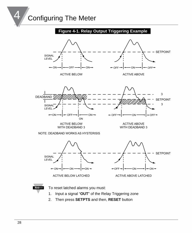
Figure 4-1. Relay Output Triggering Example
SIGNALLEVEL
SIGNALLEVEL
SIGNALLEVEL
ON ONOFF
ON
ON ON ON ON ON
ON
ON
ON
OFF
OFF
ONOFF OFF
OFF OFF
ACTIVE BELOW ACTIVE ABOVE
ACTIVE BELOWWITH DEADBAND 3
ACTIVE ABOVEWITH DEADBAND 3
ACTIVE BELOW LATCHED ACTIVE ABOVE LATCHED
SETPOINT
SETPOINT
SETPOINT
NOTE: DEADBAND WORKS AS HYSTERISIS
3
3
DEADBAND
To reset latched alarms you must:
1. Input a signal “OUT” of the Relay Triggering zone
2. Then press SETPTS and then, RESET button
29
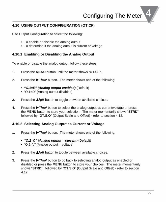
Configuring The Meter 44.10 USING OUTPUT CONFIGURATION (OT.CF)
Use Output Configuration to select the following:
• To enable or disable the analog output • To determine if the analog output is current or voltage
4.10.1 Enabling or Disabling the Analog Output
To enable or disable the analog output, follow these steps:
1. Press the MENU button until the meter shows “OT.CF”.
2. Press the T/mV button. The meter shows one of the following:
• “O.1=e” (analog output enabled) (Default) • “O.1=D” (Analog output disabled)
3. Press the /pH button to toggle between available choices.
4. Press the T/mV button to select the analog output as current/voltage or press the MENU button to store your selection. The meter momentarily shows “STRD”, followed by “OT.S.O” (Output Scale and Offset) - refer to section 4.12.
4.10.2 Selecting Analog Output as Current or Voltage
1. Press the T/mV button. The meter shows one of the following:
• “O.2=C” (analog output = current) (Default) • “O.2=V” (Analog output = voltage)
2. Press the /pH button to toggle between available choices.
3. Press the T/mV button to go back to selecting analog output as enabled or disabled or press the MENU button to store your choices. The meter momentarily shows “STRD”, followed by “OT.S.O” (Output Scale and Offset) - refer to section 4.12.
4 Configuring The Meter
30
4.10.3 Selecting Analog Output as pH or ORP( for pH/ORP Controllers only)
1. Press the T/mV button. The meter shows one of the following:
• “O.3=P” (Analog Output assigned to pH) • “O.3=O” (Analog Output assigned to ORP)
2. Press the /pH/ORP button to toggle between available choices.
3. Press the T/mV button to go back to selecting analog output as enabled or disabled or press the MENU button to store your choices. The meter momentarily shows “STRD”, followed by “OT.S.O” (Output Scale and Offset) - refer to section 4.12.
31
Configuring The Meter 44.11 CONFIGURING TEMPERATURE (C or F - “TEMP”)
If you have selected “MANU” in “A.T.C.” menu item (Section 4.1), then you have to specify the constant temperature value. Maximum/minimum values are 0 to 199.9 for C or 0 to 398.0 for F.
1. Press the MENU button until the meter shows “TEMP”.
2. Press the T/mV button. The meter shows actual constant temperature value.
3. Press the /pH button until the first digit is correct.
4. Press the T/mV button to advance to the next digit.
5. Repeat steps 3 and 4 until meter shows the desired “TEMP” value.
6. Press the MENU button to store your selection. The meter momentarily shows “STRD”, followed by “OT.S.O” (Output Scale and Offset) - refer to section 4.12.
7. Press the MENU button until the meter shows the “CAL.2 or CAL.3” menu. If the display shows “CAL.2” then proceed to Section 4.4. If the display shows “CAL.3” then proceed to Section 4.5.
C or F flashes to indicate the unit of measure.
4 Configuring The Meter
32
4.12 USING OUTPUT SCALE AND OFFSET (OT.S.O) Output Scale and Offset (“OT.S.O”) scales your analog output to be equal to the meter’s display and/or any engineering units you require. You may scale the output for direct (4-20 mA, 0-10 V, etc) or reverse acting (20-4 mA, 10-0 V, etc).
1. Press the MENU button until the meter shows “OT.S.O”.
2. Press the T/mV button. The meter shows “RD 1” (Read 1).
This is your first point of display reading.
3. Press the T/mV button again. The meter shows the last stored Low pH number with flashing 4th digit.
4. Press the /pH button to change the value of Read 1.
5. Press the T/mV button to scroll to the next digit.
6. Repeat steps 4 and 5 until the desired value is selected.
7. Press the MENU button to store your selection. The meter shows “OUT.1” (Output 1) (Low output).
8. Press the T/mV button. The meter shows the selected output.
If you select “O.2=V ” for voltage, the maximum signal you may select is 10.00 for an 0-10 Vdc signal output. If you select “O.2=C” for current, the maximum signal you may select is 20.00 for 0-20 or 4-20 mA dc
signal output.
9. Press the /pH button to enter the Output 1 signal selection. If you continue to press the /pH button, the flashing digit’s value continues to change.
10 Press the T/mV button to scroll to the next digit.
11. Repeat steps 9 and 10 until the desired value is selected.
12. Press the MENU button to store your selection. The meter shows “RD 2” (Read 2).
This is your second point of display reading.
33
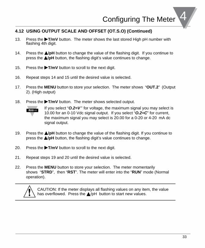
Configuring The Meter 44.12 USING OUTPUT SCALE AND OFFSET (OT.S.O) (Continued) 13. Press the T/mV button. The meter shows the last stored High pH number with flashing 4th digit.
14. Press the /pH button to change the value of the flashing digit. If you continue to press the /pH button, the flashing digit’s value continues to change.
15. Press the T/mV button to scroll to the next digit.
16. Repeat steps 14 and 15 until the desired value is selected.
17. Press the MENU button to store your selection. The meter shows “OUT.2” (Output 2). (High output)
18. Press the T/mV button. The meter shows selected output.
If you select “O.2=V ” for voltage, the maximum signal you may select is 10.00 for an 0-10 Vdc signal output. If you select “O.2=C” for current, the maximum signal you may select is 20.00 for a 0-20 or 4-20 mA dc
signal output.
19. Press the /pH button to change the value of the flashing digit. If you continue to press the /pH button, the flashing digit’s value continues to change.
20. Press the T/mV button to scroll to the next digit.
21. Repeat steps 19 and 20 until the desired value is selected.
22. Press the MENU button to store your selection. The meter momentarily shows “STRD”, then “RST”. The meter will enter into the “RUN” mode (Normal operation).
CAUTION: If the meter displays all flashing values on any item, the value has overflowed. Press the /pH button to start new values.
4 Configuring The Meter
34
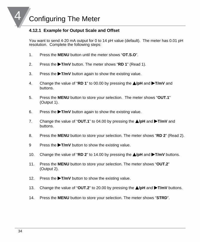
4.12.1 Example for Output Scale and Offset You want to send 4-20 mA output for 0 to 14 pH value (default). The meter has 0.01 pH resolution. Complete the following steps:
1. Press the MENU button until the meter shows “OT.S.O”.
2. Press the T/mV button. The meter shows “RD 1” (Read 1).
3. Press the T/mV button again to show the existing value.
4. Change the value of “RD 1” to 00.00 by pressing the /pH and T/mV and buttons.
5. Press the MENU button to store your selection. The meter shows “OUT.1” (Output 1).
6. Press the T/mV button again to show the existing value.
7. Change the value of “OUT.1” to 04.00 by pressing the /pH and T/mV and buttons.
8. Press the MENU button to store your selection. The meter shows “RD 2” (Read 2).
9 Press the T/mV button to show the existing value.
10. Change the value of “RD 2” to 14.00 by pressing the /pH and T/mV buttons.
11. Press the MENU button to store your selection. The meter shows “OUT.2” (Output 2).
12. Press the T/mV button to show the existing value.
13. Change the value of “OUT.2” to 20.00 by pressing the /pH and T/mV buttons.
14. Press the MENU button to store your selection. The meter shows “STRD”.
35
Selecting Setpoint Values 5
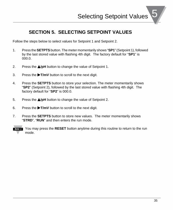
SECTION 5. SELECTING SETPOINT VALUES Follow the steps below to select values for Setpoint 1 and Setpoint 2.
1. Press the SETPTS button. The meter momentarily shows “SP1” (Setpoint 1), followed by the last stored value with flashing 4th digit. The factory default for “SP1” is 000.0.
2. Press the /pH button to change the value of Setpoint 1.
3. Press the T/mV button to scroll to the next digit.
4. Press the SETPTS button to store your selection. The meter momentarily shows “SP2” (Setpoint 2), followed by the last stored value with flashing 4th digit. The factory default for “SP2” is 000.0.
5. Press the /pH button to change the value of Setpoint 2.
6. Press the T/mV button to scroll to the next digit.
7. Press the SETPTS button to store new values. The meter momentarily shows “STRD”, “RUN” and then enters the run mode.
You may press the RESET button anytime during this routine to return to the run mode.
6 Display Messages
36
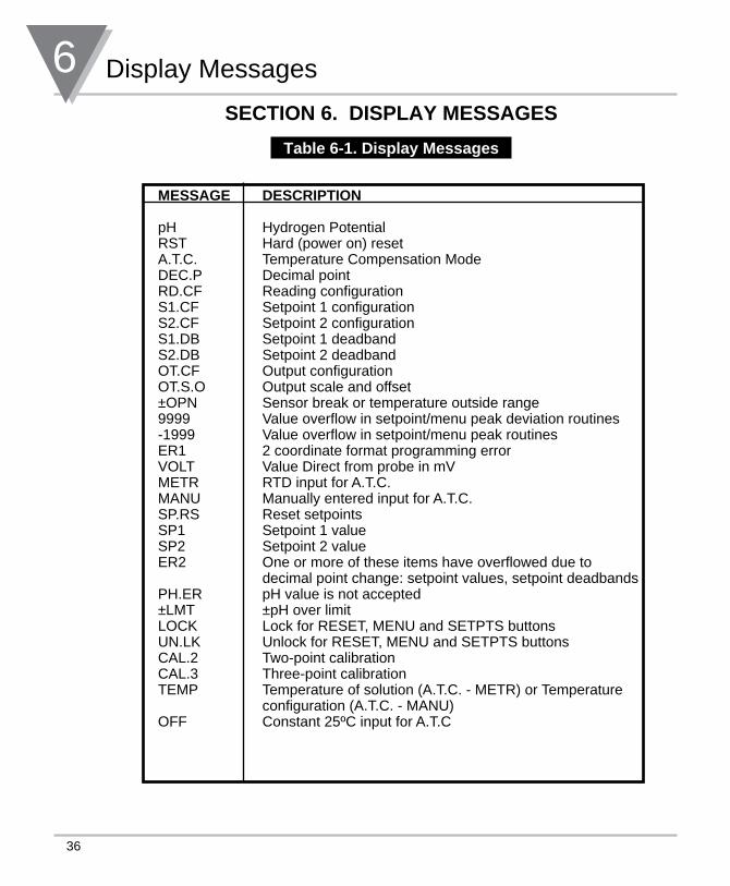
SECTION 6. DISPLAY MESSAGES
Table 6-1. Display Messages
MESSAGE DESCRIPTION pH Hydrogen Potential RST Hard (power on) reset A.T.C. Temperature Compensation Mode DEC.P Decimal point RD.CF Reading configuration S1.CF Setpoint 1 configuration S2.CF Setpoint 2 configuration S1.DB Setpoint 1 deadband S2.DB Setpoint 2 deadband OT.CF Output configuration OT.S.O Output scale and offset ±OPN Sensor break or temperature outside range 9999 Value overflow in setpoint/menu peak deviation routines -1999 Value overflow in setpoint/menu peak routines ER1 2 coordinate format programming error VOLT Value Direct from probe in mV METR RTD input for A.T.C. MANU Manually entered input for A.T.C. SP.RS Reset setpoints SP1 Setpoint 1 value SP2 Setpoint 2 value ER2 One or more of these items have overflowed due to decimal point change: setpoint values, setpoint deadbands PH.ER pH value is not accepted ±LMT ±pH over limit LOCK Lock for RESET, MENU and SETPTS buttons UN.LK Unlock for RESET, MENU and SETPTS buttons CAL.2 Two-point calibration CAL.3 Three-point calibration TEMP Temperature of solution (A.T.C. - METR) or Temperature configuration (A.T.C. - MANU) OFF Constant 25ºC input for A.T.C
37
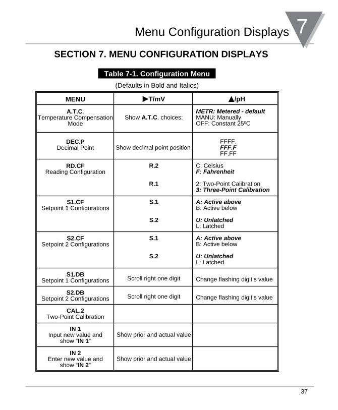
Menu Configuration Displays 7SECTION 7. MENU CONFIGURATION DISPLAYS
Table 7-1. Configuration Menu
(Defaults in Bold and Italics)
MENU
A.T.C. Temperature Compensation
Mode
DEC.PDecimal Point
RD.CFReading Configuration
S1.CF
Setpoint 1 Configurations
S2.CFSetpoint 2 Configurations
S1.DBSetpoint 1 Configurations
S2.DBSetpoint 2 Configurations
CAL.2Two-Point Calibration
IN 1Input new value and
show “IN 1”
IN 2Enter new value and
show “IN 2”
T/mV
Show A.T.C. choices:
Show decimal point position
R.2
R.1
S.1
S.2
S.1
S.2
Scroll right one digit
Scroll right one digit
Show prior and actual value
Show prior and actual value
/pH
metR: metered - defaultMANU: ManuallyOFF: Constant 25ºC
FFFF. FFF.F FF.FF
C: Celsius F: Fahrenheit 2: Two-Point Calibration 3: three-point Calibration
a: active aboveB: Active below
U: UnlatchedL: Latched
a: active aboveB: Active below
U: UnlatchedL: Latched
Change flashing digit’s value
Change flashing digit’s value
7 Menu Configuration Displays
38
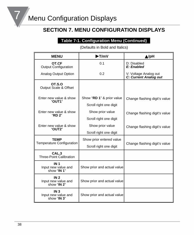
SECTION 7. MENU CONFIGURATION DISPLAYS
Table 7-1. Configuration Menu (Continued)
(Defaults in Bold and Italics)
MENU
OT.CF Output Configuration
Analog Output Option
OT.S.O
Output Scale & Offset
Enter new value & show “OUT1”
Enter new value & show “RD 2”
Enter new value & show “OUT2”
TEMPTemperature Configuration
CAL.3Three-Point Calibration
IN 1Input new value and
show “IN 1”
IN 2Input new value and
show “IN 2”
IN 3Input new value and
show “IN 3”
T/mV
0.1
0.2
Show “RD 1” & prior value
Scroll right one digit
Show prior value
Scroll right one digit
Show prior value
Scroll right one digit
Show prior entered value
Scroll right one digit
Show prior and actual value
Show prior and actual value
Show prior and actual value
/pH D: Disablede: enabled
V: Voltage Analog outC: Current analog out
Change flashing digit’s value
Change flashing digit’s value
Change flashing digit’s value
Change flashing digit’s value
39
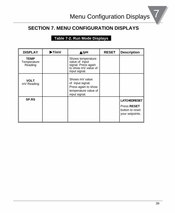
Menu Configuration Displays 7SECTION 7. MENU CONFIGURATION DISPLAYS
Table 7-2. Run Mode Displays
DISPLAY
TEMP Temperature
Reading
VOLTmV Reading
SP.RS
T/mV /pH Shows temperature value of input signal. Press again to show mV value of input signal.
Shows mV value of input signal. Press again to show temperature value of input signal.
RESET Description
LATCHED RESET
Press RESET button to reset your setpoints.
8 Setpoint Configuration Displays
40
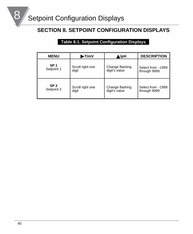
MENU
SP 1
Setpoint 1
SP 2 Setpoint 2
T/mV
Scroll right one digit
Scroll right one digit
/pH
Change flashing digit’s value
Change flashing digit’s value
DESCRIPTION
Select from -1999 through 9999
Select from -1999 through 9999
SECTION 8. SETPOINT CONFIGURATION DISPLAYS
Table 8-1. Setpoint Configuration Displays
41
Specifications 9SECTION 9. SPECIFICATIONS
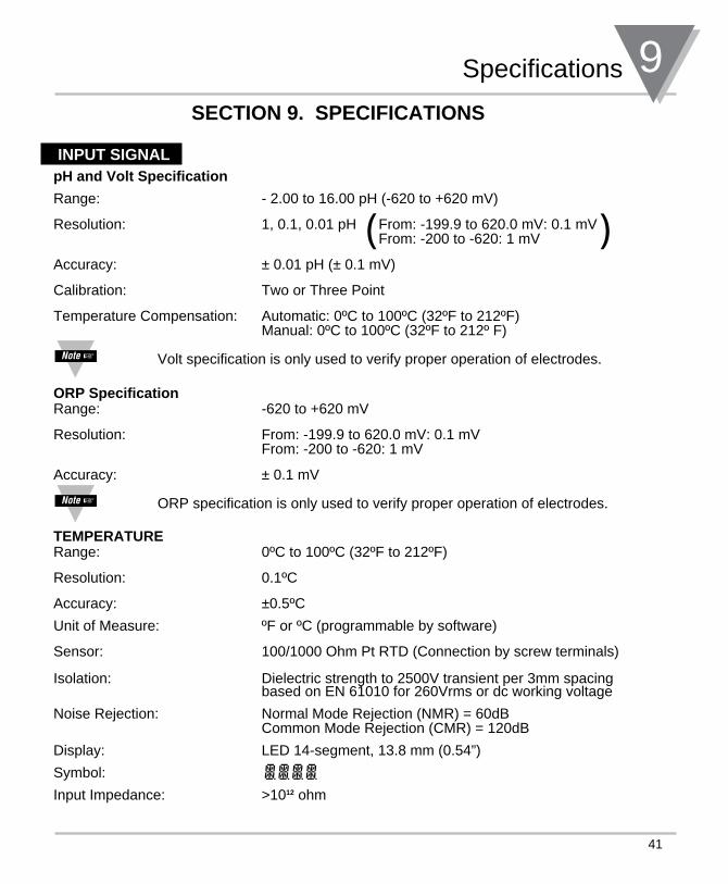
INPUT SIGNALpH and Volt Specification
Range: - 2.00 to 16.00 pH (-620 to +620 mV)
Resolution: 1, 0.1, 0.01 pH From: -199.9 to 620.0 mV: 0.1 mV From: -200 to -620: 1 mV
Accuracy: ± 0.01 pH (± 0.1 mV)
Calibration: Two or Three Point
Temperature Compensation: Automatic: 0ºC to 100ºC (32ºF to 212ºF) Manual: 0ºC to 100ºC (32ºF to 212º F)
Volt specification is only used to verify proper operation of electrodes.
ORP SpecificationRange: -620 to +620 mV
Resolution: From: -199.9 to 620.0 mV: 0.1 mV From: -200 to -620: 1 mV
Accuracy: ± 0.1 mV
ORP specification is only used to verify proper operation of electrodes.
TEMPERATURERange: 0ºC to 100ºC (32ºF to 212ºF)
Resolution: 0.1ºC
Accuracy: ±0.5ºC
Unit of Measure: ºF or ºC (programmable by software)
Sensor: 100/1000 Ohm Pt RTD (Connection by screw terminals)
Isolation: Dielectric strength to 2500V transient per 3mm spacing based on EN 61010 for 260Vrms or dc working voltage
Noise Rejection: Normal Mode Rejection (NMR) = 60dB Common Mode Rejection (CMR) = 120dB
Display: LED 14-segment, 13.8 mm (0.54”)
Symbol:
Input Impedance: >1012 ohm
( )
9 Specifications
42
SECTION 9. SPECIFICATIONS (Continued)
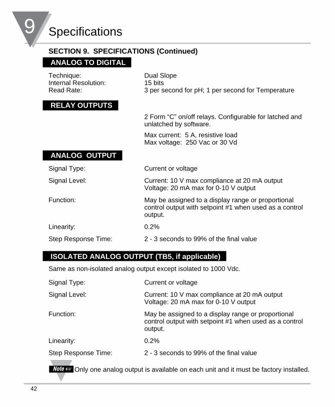
ANALOG TO DIGITAL
Technique: Dual Slope Internal Resolution: 15 bits Read Rate: 3 per second for pH; 1 per second for Temperature
RELAY OUTPUTS
2 Form “C” on/off relays. Configurable for latched and unlatched by software.
Max current: 5 A, resistive load Max voltage: 250 Vac or 30 Vd
ANALOG OUTPUT
Signal Type: Current or voltage
Signal Level: Current: 10 V max compliance at 20 mA output Voltage: 20 mA max for 0-10 V output
Function: May be assigned to a display range or proportional control output with setpoint #1 when used as a control output.
Linearity: 0.2%
Step Response Time: 2 - 3 seconds to 99% of the final value
ISOLATED ANALOG OUTPUT (TB5, if applicable)
Same as non-isolated analog output except isolated to 1000 Vdc.
Signal Type: Current or voltage
Signal Level: Current: 10 V max compliance at 20 mA output Voltage: 20 mA max for 0-10 V output
Function: May be assigned to a display range or proportional control output with setpoint #1 when used as a control output.
Linearity: 0.2%
Step Response Time: 2 - 3 seconds to 99% of the final value Only one analog output is available on each unit and it must be factory installed.
43
Specifications 9SECTION 9. SPECIFICATIONS (Continued)
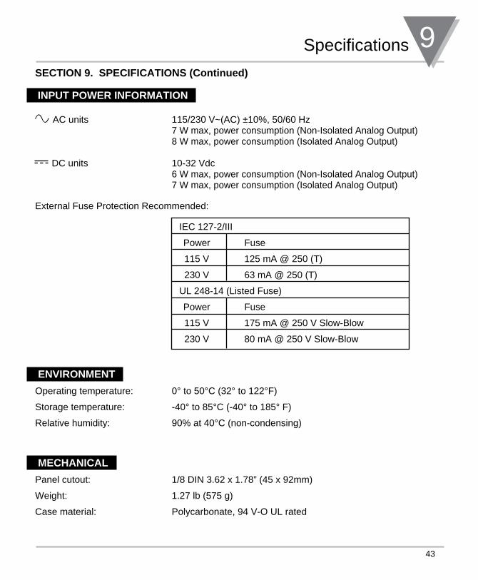
INPUT POWER INFORMATION
External Fuse Protection Recommended:
IEC 127-2/III
Power Fuse
115 V 125 mA @ 250 (T)
230 V 63 mA @ 250 (T)
UL 248-14 (Listed Fuse)
Power Fuse
115 V 175 mA @ 250 V Slow-Blow
230 V 80 mA @ 250 V Slow-Blow
ENVIRONMENT
Operating temperature: 0° to 50°C (32° to 122°F)
Storage temperature: -40° to 85°C (-40° to 185° F)
Relative humidity: 90% at 40°C (non-condensing)
MECHANICAL
Panel cutout: 1/8 DIN 3.62 x 1.78” (45 x 92mm)
Weight: 1.27 lb (575 g)
Case material: Polycarbonate, 94 V-O UL rated
~ AC units 115/230 V~(AC) ±10%, 50/60 Hz 7 W max, power consumption (Non-Isolated Analog Output)
8 W max, power consumption (Isolated Analog Output)
DC units 10-32 Vdc 6 W max, power consumption (Non-Isolated Analog Output)
7 W max, power consumption (Isolated Analog Output)
9 Specifications
44
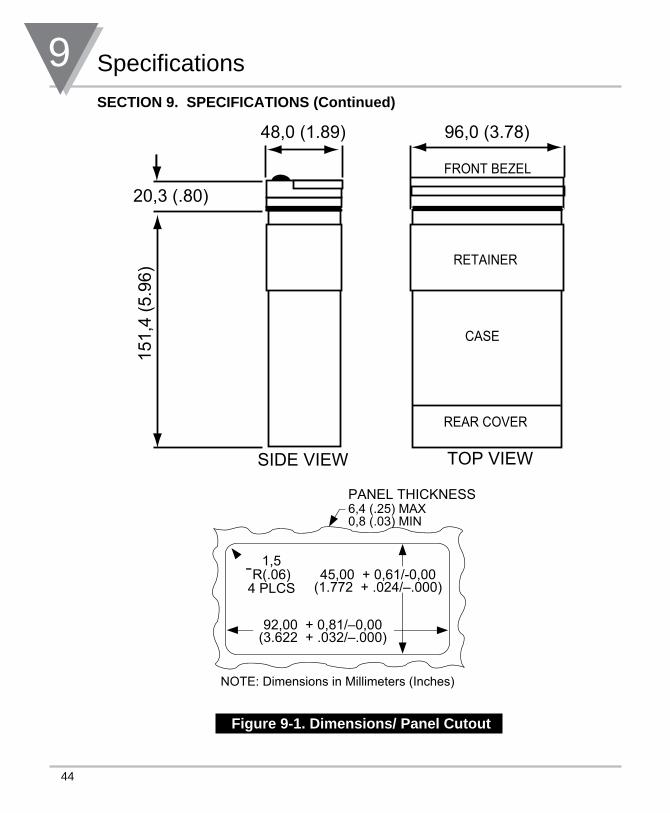
SECTION 9. SPECIFICATIONS (Continued)
Figure 9-1. Dimensions/ Panel Cutout
SIDE VIEW TOP VIEW
CASE
REAR COVER
96,0 (3.78)48,0 (1.89)
20,3 (.80)
151,
4 (5
.96)
RETAINER
FRONT BEZEL
45,00 + 0,61/-0,00(1.772 + .024/–.000)
92,00 + 0,81/–0,00(3.622 + .032/–.000)
PANEL THICKNESS
1,5R(.06)
4 PLCS
6,4 (.25) MAX0,8 (.03) MIN
NOTE: Dimensions in Millimeters (Inches)
45
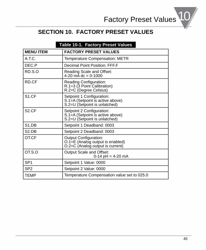
Factory Preset Values 10SECTION 10. FACTORY PRESET VALUES
Table 10-1. Factory Preset Values
MENU ITEM FACTORY PRESET VALUES
A.T.C. Temperature Compensation: METR
DEC.P Decimal Point Position: FFF.F
RD.S.O Reading Scale and Offset:4-20 mA dc = 0-1000
RD.CF Reading Configuration:R.1=3 (3 Point Calibration)R.2=C (Degree Celsius)
S1.CF Setpoint 1 Configuration:S.1=A (Setpoint is active above)S.2=U (Setpoint is unlatched)
S2.CF Setpoint 2 Configuration:S.1=A (Setpoint is active above)S.2=U (Setpoint is unlatched)
S1.DB Setpoint 1 Deadband: 0003
S2.DB Setpoint 2 Deadband: 0003
OT.CF Output Configuration:O.1=E (Analog output is enabled)O.2=C (Analog output is current)
OT.S.O Output Scale and Offset: 0-14 pH = 4-20 mA
SP1 Setpoint 1 Value: 0000
SP2 Setpoint 2 Value: 0000
TEMP Temperature Compensation value set to 025.0
46
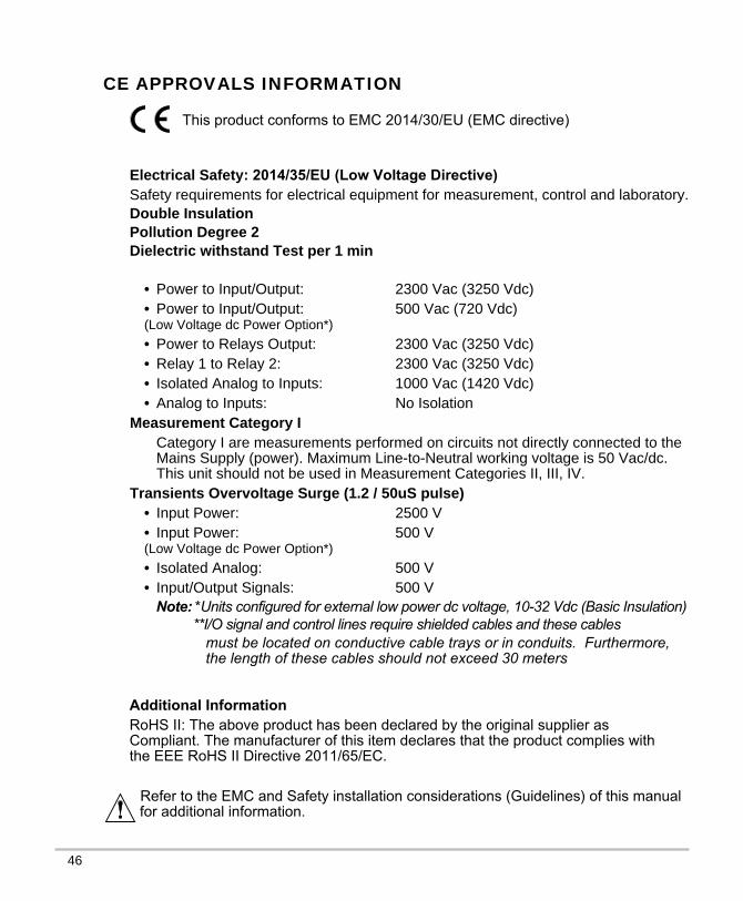
CE APPROVALS INFORMATION
This product conforms to EMC 2014/30/EU (EMC directive)
Electrical Safety: 2014/35/EU (Low Voltage Directive) Safety requirements for electrical equipment for measurement, control and laboratory.Double InsulationPollution Degree 2Dielectric withstand Test per 1 min
• Power to Input/Output: 2300 Vac (3250 Vdc)• Power to Input/Output: 500 Vac (720 Vdc) (Low Voltage dc Power Option*)
• Power to Relays Output: 2300 Vac (3250 Vdc)• Relay 1 to Relay 2: 2300 Vac (3250 Vdc)• Isolated Analog to Inputs: 1000 Vac (1420 Vdc)• Analog to Inputs: No Isolation
Measurement Category ICategory I are measurements performed on circuits not directly connected to the Mains Supply (power). Maximum Line-to-Neutral working voltage is 50 Vac/dc. This unit should not be used in Measurement Categories II, III, IV.
Transients Overvoltage Surge (1.2 / 50uS pulse)• Input Power: 2500 V• Input Power: 500 V(Low Voltage dc Power Option*) • Isolated Analog: 500 V• Input/Output Signals: 500 V
Note: *Units configured for external low power dc voltage, 10-32 Vdc (Basic Insulation) **I/O signal and control lines require shielded cables and these cables
Additional InformationRoHS II: The above product has been declared by the original supplier as Compliant. The manufacturer of this item declares that the product complies with the EEE RoHS II Directive 2011/65/EC.
must be located on conductive cable trays or in conduits. Furthermore, the length of these cables should not exceed 30 meters
Refer to the EMC and Safety installation considerations (Guidelines) of this manualfor additional information.
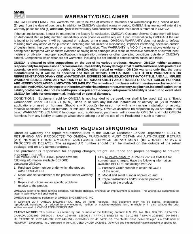
FOR WARRANTY RETURNS, please have the following information available BEFORE contacting OMEGA:1. Purchase Order number under which the product
was PURCHASED,2. Model and serial number of the product under warranty,
and3. Repair instructions and/or specific problems
relative to the product.
FOR NON-WARRANTY REPAIRS, consult OMEGA for current repair charges. Have the following information available BEFORE contacting OMEGA:1. Purchase Order number to cover the COST
of the repair,2. Model and serial number of product, and3. Repair instructions and/or specific problems
relative to the product.
WARRANTY/DISCLAIMEROMEGA ENGINEERING, INC. warrants this unit to be free of defects in materials and workmanship for a period of one (1) year from the date of purchase. In addition to OMEGA’s standard warranty period, OMEGA Engineering will extend the warranty period for one (1) additional year if the warranty card enclosed with each instrument is returned to OMEGA.
If the unit malfunctions, it must be returned to the factory for evaluation. OMEGA’s Customer Service Department will issue an Authorized Return (AR) number immediately upon phone or written request. Upon examination by OMEGA, if the unit is found to be defective, it will be repaired or replaced at no charge. OMEGA’s WARRANTY does not apply to defects resulting from any action of the purchaser, including but not limited to mishandling, improper interfacing, operation outside of design limits, improper repair, or unauthorized modification. This WARRANTY is VOID if the unit shows evidence of having been tampered with or shows evidence of having been damaged as a result of excessive corrosion; or current, heat, moisture or vibration; improper specification; misapplication; misuse or other operating conditions outside of OMEGA’s control. Components which wear are not warranted, including but not limited to contact points, fuses, and triacs.
OMEGA is pleased to offer suggestions on the use of its various products. However, OMEGA neither assumes responsibility for any omissions or errors nor assumes liability for any damages that result from the use of its products in accordance with information provided by OMEGA, either verbal or written. OMEGA warrants only that the parts manufactured by it will be as specified and free of defects. OMEGA MAKES NO OTHER WARRANTIES OR REPRESENTATIONS OF ANY KIND WHATSOEVER, EXPRESS OR IMPLIED, EXCEPT THAT OF TITLE, AND ALL IMPLIED WARRANTIES INCLUDING ANY WARRANTY OF MERCHANTABILITY AND FITNESS FOR A PARTICULAR PURPOSE ARE HEREBY DISCLAIMED. LIMITATION OF LIABILITY: The remedies of purchaser set forth herein are exclusive, and the total liability of OMEGA with respect to this order, whether based on contract, warranty, negligence, indemnification, strict liability or otherwise, shall not exceed the purchase price of the component upon which liability is based. In no event shall OMEGA be liable for consequential, incidental or special damages.
CONDITIONS: Equipment sold by OMEGA is not intended to be used, nor shall it be used: (1) as a “Basic Component” under 10 CFR 21 (NRC), used in or with any nuclear installation or activity; or (2) in medical applications or used on humans. Should any Product(s) be used in or with any nuclear installation or activity, medical application, used on humans, or misused in any way, OMEGA assumes no responsibility as set forth in our basic WARRANTY/DISCLAIMER language, and, additionally, purchaser will indemnify OMEGA and hold OMEGA harmless from any liability or damage whatsoever arising out of the use of the Product(s) in such a manner.
RETURN REQUESTS/INQUIRIESDirect all warranty and repair requests/inquiries to the OMEGA Customer Service Department. BEFORE RETURNING ANY PRODUCT(S) TO OMEGA, PURCHASER MUST OBTAIN AN AUTHORIZED RETURN (AR) NUMBER FROM OMEGA’S CUSTOMER SERVICE DEPARTMENT (IN ORDER TO AVOID PROCESSING DELAYS). The assigned AR number should then be marked on the outside of the return package and on any correspondence.
The purchaser is responsible for shipping charges, freight, insurance and proper packaging to prevent breakage in transit.
OMEGA’s policy is to make running changes, not model changes, whenever an improvement is possible. This affords our customers the latest in technology and engineering.
OMEGA is a registered trademark of OMEGA ENGINEERING, INC.
© Copyright 2017 OMEGA ENGINEERING, INC. All rights reserved. This document may not be copied, photocopied, reproduced, translated, or reduced to any electronic medium or machine-readable form, in whole or in part, without the prior written consent of OMEGA ENGINEERING, INC.
PATENT NOTICE: This product is covered by one or more of the following patents: U.S. Pat. No. Des. 336,895; 5,274,577 / CANADA 2052599; 2052600 / ITALY 1249456; 1250938 / FRANCE BREVET No. 91 12756 / SPAIN 2039150; 2048066 / UK PATENT No. GB2 249 837; GB2 248 954 / GERMANY DE 41 34398 C2. The “Meter Case Bezel Design” is a trademark of NEWPORT Electronics, Inc., registered in the U.S. USED UNDER LICENSE. Other US and International Patents pending or applied for.

M1570/0317 11799ML-95 Rev.E
Where Do I Find Everything I Need for Process Measurement and Control?
OMEGA…Of Course!Shop on line at omega.com®
TEMPERATURER Thermocouple, RTD & Thermistor Probes, Connectors, Panels & Assemblies R Wire: Thermocouple, RTD & ThermistorR Calibrators & Ice Point ReferencesR Recorders, Controllers & Process MonitorsR Infrared Pyrometers
PRESSURE, STRAIN AND FORCER Transducers & Strain GaugesR Load Cells & Pressure GaugesR Displacement TransducersR Instrumentation & Accessories
FLOW/LEVELR Rotameters, Gas Mass Flowmeters & Flow ComputersR Air Velocity IndicatorsR Turbine/Paddlewheel SystemsR Totalizers & Batch Controllers
pH/CONDUCTIVITYR pH Electrodes, Testers & AccessoriesR Benchtop/Laboratory MetersR Controllers, Calibrators, Simulators & PumpsR Industrial pH & Conductivity Equipment
DATA ACQUISITIONR Data Acquisition & Engineering SoftwareR Communications-Based Acquisition SystemsR Plug-in Cards for Apple, IBM & CompatiblesR Datalogging SystemsR Recorders, Printers & Plotters
HEATERSR Heating CableR Cartridge & Strip HeatersR Immersion & Band HeatersR Flexible HeatersR Laboratory Heaters
ENVIRONMENTAL MONITORING AND CONTROLR Metering & Control InstrumentationR RefractometersR Pumps & TubingR Air, Soil & Water MonitorsR Industrial Water & Wastewater TreatmentR pH, Conductivity & Dissolved Oxygen Instruments