micropulse contents transducers profile seriesdocs-europe.electrocomponents.com/webdocs/098f/... ·...
TRANSCRIPT

ContentsProfile series
MicropulseTransducers
Generaldata
Analoginterface
Digitalpulseinterface
SSDinterface
CANopeninterface
PROFIBUS-DPinterface
Magnetsfloating
Magnetscaptive,control arm
P.1
P.2 General dataP.4 Analog
interfaceP.6 Digital
pulse interfaceP.8 SSD
interfaceP.10 CANopen interfaceP.12 PROFIBUS-DP
interfaceP.14 Magnets
floatingP.16 Magnets
captive, control arm
BTLP

BTL Profile
100 g/6 ms per IEC 60068-2-2712 g, 10...2000 Hz per IEC 60068-2-6
yesTranszorb protection diodes
500 V (GND to housing)IP 67 (with BKS-S... IP 67 connector attached)
Anodized aluminumCompression clamps
Connector
EN 55011 Group 1, Class AIEC 61000-4-2 Severity Level 3IEC 61000-4-3 Severity Level 3IEC 61000-4-4 Severity Level 4IEC 61000-4-6 Severity Level 3
0050, 0100, 0130, 0150, 0175, 0200, 0225, 0250, 0300,0350, 0360, 0400, 0450, 0500, 0550, 0600, 0650, 0700,0750, 0800, 0850, 0900, 0950, 1000, 1100, 1200, 1250,1300, 1400, 1500, 1600, 1700, 1750, 1800, 1900, 2000,2250, 2500, 2750, 3000, 3250, 3500, 3550, 3750, 4000.
Series
Shock loadVibrationPolarity reversal protectedOvervoltage protectionDielectric constantEnclosure rating per IEC 60529Housing materialHousing attachmentConnection typeEMC testing:RF emissionStatic electricity (ESD)Electromagnetic fields (RFI)Fast transients (BURST)Line-carried noise,induced by high-frequency fieldsStandard nominal strokes [mm]
General dataProfile series
Balluff Micropulsetransducers in the Profilehousing, with their me-chanical design, the highprotection rating, and theirease of installation, arean alternative to linear trans-ducers such as potentio-meters, glass scales, andLVDTs. The linear sensingelement is protected in analuminum extrusion.The measuring point alongthe sensing element (wave-guide) is indicated by apassive marker (magnet),which needs no power.Measuring stroke rangesbetween 50 and 4000 mmare available.
– non-contact detectionof the actual position
– IP 67, insensitiveto contamination
– wear-free– insensitive to shock and
vibration– absolute output signal– resolution up to 0.0004"
(0.001 mm)(depending on processorused)
– direct signal processing orthrough processor cardsfor interfacing with anycontrol system or stand-alone operation
MicropulseTransducers
Included:– Transducer (select your interface
starting page P.4)– User's guide– Mounting feet with isolation washers and
screws
▼ Please order separately:Magnets starting page P.14Connectors starting page BKS.3
P.2

BTL Profilefloating or captive
P.3
MicropulseTransducers
General dataProfile series
Transducer with captive magnet, S 32 connection with BKS-S 33M connectorfor transducers with analog interface, digital pulse interface and SSD interface Page P.4...P.9
Transducer with floating magnet, S 32 connection with BKS-S 32M/BKS-S 32M-C connectorfor transducers with analog interface, digital pulse interface and SSD interface Page P.4...P.9
Nominal stroke
Nominal stroke
Installation length
Installation length
SeriesMagnets starting Page P.14
CANopen S 92 connection with BKS-S 92-00 connectorfor transducer with CANopen interface Page P.10
PROFIBUS-DP S103 connection with BKS-S 103-00, BKS-S 105-00 and BKS-S 48-15-CP-_ _for transducer with PROFIBUS-DP interface Page P.12
PROFIBUS-DP S 86 connection with BKS-S 86-00 connectorfor transducer with PROFIBUS-DP interface Page P.12
http://www.balluff.de
Generaldata
Analoginterface
Digitalpulseinterface
SSDinterface
CANopeninterface
PROFIBUS-DPinterface
Magnetsfloating
Magnetscaptive,control arm
BTLP
BKS
Page BKS.3

SeriesOutput signalTransducer interfaceInput interface
Ordering code
OutputOutput voltageOutput currentLoad currentmax. rippleLoad resistanceSystem resolution
HysteresisRepeatabilitySampling ratemax. non-linearity
Temperature coefficient Voltage outputCurrent output
Supply voltageCurrent drawPolarity reversal protectedOvervoltage protectionDielectric constantOperating temperatureStorage temperature
Pin assignments Pin ColorOutput signals 1 YE
2 GY3 PK5 GN
Supply voltage 6 BU7 BN8 WH
Connect shield to housing
The analog outputs of theprofile series are potential-free with respect to the inputvoltage. The isolationis galvanic using DC/DCconverters.
Analog type BTL transducersare available in various out-put configurations: 0...10V,4...20 mA, 0...20 mAand -10...10V, with risingand falling output slope.
Analog interfaceProfile series
MicropulseTransducers
P.4
Included:– Transducer– Mounting feet with isolation washers and screws– User's guide
Please order separately:Magnets starting page P.14Connectors starting page BKS.....3
▼
Micropulse Transducers – a non-contact alternativeto contacting feedback devices
Potentiometer connections, block diagram
Micropulse transducer connections, block diagram

BTL Profileanalog
Aanalog
BTL5-A11-M_ _ _ _-P-S 32
potential-free0...10 V and 10...0 V
max. 5 mA≤ 5 mV
≤≤≤≤≤ 0.1 mV
BTL5-A11...
0 V Output10...0 V0...10 V
GND+24 V DC
(GND)
BTL Profileanalog
Ganalog
BTL5-G11-M_ _ _ _-P-S 32
potential-free–10...10 V and 10...–10 V
max. 5 mA≤ 5 mV
≤≤≤≤≤ 0.1 mV
BTL5-G11...
0 V Output10...–10 V–10 ... 10V
GND+24 V DC
(GND)
BTL Profileanalog
Canalog
BTL5-C1_-M_ _ _ _-P-S 32
potential-free
0...20 mA or 20...0 mA
≤ 500 Ohms≤≤≤≤≤ 0.2 µA
BTL5-C10... BTL5-C17...0...20 mA 20...0 mA
0 V Output10...0 V0...10 V
GND+24 V DC
(GND)
BTL Profileanalog
Eanalog
BTL5-E1_-M_ _ _ _-P-S 32
potential-free
4...20 mA or 20...4 mA
≤ 500 Ohm≤≤≤≤≤ 0.2 µA
BTL5-E10... BTL5-E17...4...20 mA 20...4 mA
0 V Output10...0 V0...10 V
GND+24 V DC
(GND)
1 risingand falling(for A and G)
0 rising7 falling
(for C and E)
BTL5-E1_-M_ _ _ _-P-S 32
Outputsignal
Standardnominal strokes [mm]
Analog interfaceProfile series
MicropulseTransducers
P.5
Ordering example:▼▼
potential-free up to 4000 mm
http://www.balluff.de
Generaldata
Analoginterface
Digitalpulseinterface
SSDinterface
CANopeninterface
PROFIBUS-DPinterface
Magnetsfloating
Magnetscaptive,control arm
BTLP
BKS
Page BKS.3Please enter code for outputsignal and nominal strokelength in ordering code.
Preferred models interface ABTL5-A11-M_ _ _ _-P-S 32highlighted in blue areavailable from stock.
0050, 0100, 0130, 0150, 0175, 0200, 0225, 0250,0300, 0350, 0360, 0400, 0450, 0500, 0550, 0600,0650, 0700, 0750, 0800, 0850, 0900, 0950, 1000,1100, 1200, 1250, 1300, 1400, 1500, 1600, 1700,1750, 1800, 1900, 2000, 2250, 2500, 2750, 3000,3250, 3500, 3550, 3750, 4000
≤ 4 µmSystem resolution/min. 2 µm
fSTANDARD = 1 kHz±100 µm to 500 mm nominal stroke
±0.02 % 500...4000 mm nominal stroke[150 µV/°C + (5 ppm/°C × P × U/L)] × ∆T[0.6 µA/°C + (10 ppm/°C × P × I/L)] × ∆T
24 V DC ±20 %≤ 150 mA
yesTranszorb protection diodes500 V (Ground to housing)
–40...+85 °C–40...+100 °C

Series
Transducer interfaceInput interface
Ordering code
System resolutionRepeatabilityResolutionHysteresisSampling ratemax. non-linearity
Temperature coefficient of overall systemSupply voltageCurrent drawOperating temperatureStorage temperature
Pin assignments Pin ColorIn-/output signals Input 1 YE
Output 2 GYInput 3 PKOutput 5 GN
Supply voltage 6 BU7 BN8 WH
Connect shield to housing
Block diagram of P-interface
Highly precise digitizingof the P pulse signal
Companies developing theirown control and processingelectronics can create ahighly accurate P-interfacecost effectively and with aminimum of effort using theBalluff digitizing chip. Thedigitizing chip was deve-loped as a high-resolution,configurable ASIC for theMicropulse P-interface.
Digitizing chip 44QFP
CPUcontroller
4/8bit bus
5 V Osc.
INIT
Micropulse transducerwith 1 to 4 magnets
Controller orProcessing electronics
P pulse signal
Benefits
– High resolution:the actual 1 µm of the BTLinternally is fully supported bythe 5 µm resolution of thechip (at low clock frequency2 or 20 MHz)
– Position data from 4 magnetscan be processedsimultaneously
– 4/8-bit processor interface
Digitale pulse interfaceProfile series
MicropulseTransducers
P.6
P Interface
Compatible with BTAprocessors and various OEMcontrols, e.g., Siemens,Schleicher, B & R, Bosch,Mitsubishi, Schiele, Parker,Esitron, Philips, WAGO etc..Reliable signal transmission,even over cable lengths upto 500 m between BTA andBTL, is assured by theespecially noise-immuneRS485 differential driversand receivers. Noise signalsare effectively suppressed.
M Interface
The I and M interfaces arecontrol-specific interfacevariations.
I Interface
Used for parallel operationof multiple transducers,for example up to 4 trans-ducers can be controlled bya single BTA-M/PMT card(see starting Page BTA.3).
ASIC INFO:+49 (0) 71 58/1 73-2 41
cost-effective

BTL Profile
Pulse IPulse I
BTL5-I1-M_ _ _ _-P-S 32
BTL5-I1-M...INIT
START/STOPINIT
START/STOPGND
+24 V DC(GND)
BTL Profile
Pulse MPulse M
BTL5-M1-M_ _ _ _-P-S 32
BTL5-M1-M...INIT
START/STOPINIT
START/STOPGND
+24 V DC(GND)
processing-dependent2 µm or ±1 digit depending on processing electronics
≤ 2 µm≤ 4 µm
fSTANDARD = 1 kHz = ≤ 1400 mm±100 µm up to 500 mm nominal stroke±0,02 % 500...4000 mm nominal stroke
(6 µm + 5 ppm × L)/°C24 V DC ±20 %
≤ 90 mA–40...+85 °C
–40...+100 °C
▼Digital pulse interfaceProfile series
MicropulseTransducers
P.7
Please enter code for nominalstroke in ordering code!
Preferred models interface PBTL5-P1-M_ _ _ _-P-S 32highlighted in blue are availablefrom stock.
Ordering example:BTL5-P1-M_ _ _ _-P-S 32
Standardnominal strokes [mm]
▼
Included:– Transducer– Mounting feet with isolation washers and screws– User's guide
Please order separately:Magnets starting page P.14Connectors starting page BKS.3
▼
http://www.balluff.de
Generaldata
Analoginterface
Digitalpulseinterface
SSDinterface
CANopeninterface
PROFIBUS-DPinterface
Magnetsfloating
Magnetscaptive,control arm
Temperature range –40...+85 °C
BTLP
BKS
Page BKS.3
BTA
Page BTA.3
0050, 0100, 0130, 0150, 0175, 0200, 0225, 0250,0300, 0350, 0360, 0400, 0450, 0500, 0550, 0600,0650, 0700, 0750, 0800, 0850, 0900, 0950, 1000,1100, 1200, 1250, 1300, 1400, 1500, 1600, 1700,1750, 1800, 1900, 2000, 2250, 2500, 2750, 3000,3250, 3500, 3550, 3750, 4000
BTL Profile
Pulse PPulse P
BTL5-P1-M_ _ _ _-P-S 32
BTL5-P1-M... INIT
START/STOPINIT
START/STOPGND
+24 V DC(GND)

SSD interfaceProfile series
SSD Interface
Synchronous serial datatransmission for controlsmade by Siemens,Schleicher, B & R, PEES,Schiele, Parker, Esitron, PEPetc. as well as for BalluffBDD-AM 10-...-1-SSD andBDD-CC 08-1-SSD display/controllers.
MicropulseTransducers
P.8
Reliable signal transmission,even over cable lengths ofup to 400 m between controland BTL transducer isassured by especiallynoise-immune RS485/422differential line drivers andreceivers. Any noise signalsare effectively suppressed.
Clock frequency is afunction of cable length
Cable length< 25 m< 50 m<100 m<200 m<400 m
Clock freq.< 1000 kHz< 500 kHz< 400 kHz< 200 kHz< 100 kHz
BTL5-S1... with processor/controller, wiring example
Processororcontroller
TransducerBTL5-S1...
Super-fast 2 kHz Sampling rate

BTL Profilesynchronous serial
Ssynchronous serial
BTL5-S1_ _-M_ _ _ _-P-S 32
±1 digit1, 5, 10, 20 or 40 µm
≤ 1 DigitfSTANDARD = 2 kHz
±30 µm at 5 und 10 µm Resolution or ≤ ±2 LSB(6 µm + 5 ppm × L) /°C
24 V DC ±20 %≤ 80 mA
–40...+85 °C–40...+100 °C
+Clk +Data–Clk
–DataGND
+24 V DCmust remain unconnected
SeriesOutput signalTransducer interfaceInput interface
Ordering code
RepeatabilitySystem resolution depending on version (LSB)HysteresisSampling ratemax. non-linearityTemperature coefficient of overall systemSupply voltageCurrent drawOperating temperatureStorage temperature
Pin assignments Pin ColorControl and 1 YEdata signals 2 GY
3 PK5 GN
Supply 6 BUvoltage (external) 7 BN
8 WH
▼
Please enter code for coding,system resolution and nominalstroke length in ordering code.
Preferred models interface SBTL5-S112-M_ _ _ _-P-S 32highlighted in blue areavailable from stock.
0100, 0130, 0150, 0175,0200, 0225, 0250, 0300,0350, 0360, 0400, 0450,0500, 0550, 0600, 0650,0700, 0750, 0800, 0850,0900, 0950, 1000, 1100,1200, 1250, 1300, 1400,1500, 1600, 1700, 1750,1800, 1900, 2000, 2250,2500, 2750, 3000, 3250,3500, 3550, 3750, 4000
SSD interfaceProfile series
MicropulseTransducers
P.9
0 Binary code rising (24 bits)1 Gray code rising (24 bits)6 Binary code rising (25 bits)7 Gray code rising (25 bits)
Ordering example:BTL5-S1_ _-M_ _ _ _-P-S 32
Coding
1 1 µm2 5 µm3 10 µm4 20 µm5 40 µm
Systemresolution
Standardnominal strokes [mm]
▼▼
Pulse sequence
super linear
http://www.balluff.de
Generaldata
Analoginterface
Digitalpulseinterface
SSDinterface
CANopeninterface
PROFIBUS-DPinterface
Magnetsfloating
Magnetscaptive,control arm
BTLP
BKS
Page BKS.3Included:– Transducer– Mounting feet with isolation washers and screws– User's guide
Please order separately:Magnets starting page P.14Connectors starting page BKS.....3
CANopen interfaceProfile series
MicropulseTransducers
P.10
CANopen interface
Based on CAN(ISO/IEC 7498 andDIN ISO 11898), CANopenprovides a Layer-7implementation for industrialCAN networks. The serialdata protocol of the CANspecification is definedaccording to the producer-consumer principle asopposed to most otherfieldbus protocols. Thiseliminates target addressingof the process data. Eachbus station decides for itselfhow the received data areprocessed.
The CANopen interface ofthe Micropulse transducer iscompatible with CANopenconforming with CiA Stan-dard DS301 Rev. 3.0, andwith CAL and Layer 2 CANnetworks.
CAN-BUS features
– Line topology, starstructure also possibleusing repeaters
– Cost-effective 2-wirecabling
– Fast response times, highdata integrity using CRC,hamming distance of 6
– Potential-free datatransmission (RS485)
– 1 Mbps at cable lengths< 25 m
– Number of stationsprotocol-limited to 127
– Using multiple magnets:A minimum spacingof > 65 mm must bemaintained.
CANopen offers a high levelof flexibility with respect tofunctionality and dataexchnge. Using a standarddata sheet in the form of anEDS file it is easy to link theMicropulse transducers toany CANopen system.
Process Data Object(PDO)
Micropulse transducers sendtheir position informationoptionally in one or twoPDOs with 8 bytes of dataeach. The contents of thePDOs is free configurable.The following informationcan be sent:
– Current magnet positionwith resolution in 5 µmsteps
– Current velocity of themagnet with resolutionselectable in 0.1mm/ssteps
– Current status of the fourfreely programmablecams.
Synchronisation Object(SYNC)
Serves as a net-wide triggerfor synchronizing all networkparticipants. When theSYNC object is received, allMicropulse transducersactive on the bus store theircurrent position and velocityinformation and then send itsequentially to the control.This assures time-synchronous capture of themeasured values.
Emergency Object
This object is sent with thehighest priority. This is usedfor example for errormessages when cam stateschange.
Service Data Object (SDO)
Service Data Objects trans-mit the parameters for thetransducer configuration.The transducer configurationmay be carried out on thebus by the controller, oroffline using a PC with aconfiguration tool which runsunder Windows. Theconfiguration is stored in thetransducer in a non-volatilememory.
CANopen Draft Standard 406 (Encoder Profile)
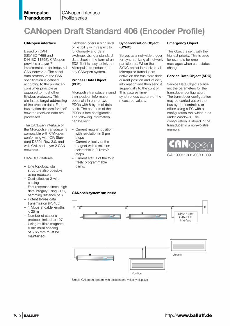
Simple CANopen system with position and velocity displays
CANopen system structure
SPS/PC mitCAN-BUSinterface
certifiedCiA 199911-301v30/11-009
R R
http://www.balluff.de
Velocity
Position

SeriesOutput signalTransducer interfaceInput interface
Ordering code
CANopen VersionCANopen-interfaceRepeatabilitySystem resolution Positionconfigurable VelocityHysteresisSampling ratemax. non-linearityTemperature coefficient of overall systemMagnet traverse speedSupply voltageCurrent drawOperating temperatureStorage temperature
Cable length [m] per CiA DS301Baud rate [kBaud] per CiA DS301
Pin assignments Pin ColorControl and 1 WHdata signals 4 GY
5 GNSupply 2 BNvoltage (external) 3 BU
CANopen interfaceProfile series
MicropulseTransducers
P.11
Using the CANopen interfaceand cable lengths up to2500 m, the signal is sent at alength-dependent baud rateto the control. The high noiseimmunity of the connection isachieved using differentialdrivers and by the data moni-toring scheme.
▼ Please enter code for software configuration, baud rateand nominal stroke length in order code.
Ordering example:BTL5-H1_ _-M_ _ _ _-P-S 92
Softwareconfiguration
0050, 0100, 0130, 0150,0175, 0200, 0225, 0250,0300, 0350, 0360, 0400,0450, 0500, 0550, 0600,0650, 0700, 0750, 0800,0850, 0900, 0950, 1000,1100, 1200, 1250, 1300,1400, 1500, 1600, 1700,1750, 1800, 1900, 2000,2250, 2500, 2750, 3000,3250, 3500, 3550, 3750,4000
0 1 MBaud1 800 kBaud2 500 kBaud3 250 kBaud4 125 kBaud5 100 kBaud6 50 kBaud7 20 kBaud8 10 kBaud
1 1 × Position and1 × Velocity
2 2 × Position and2 × Velocity
3 4 × Position
Baudrate
Standardnominal strokes [mm]
Included:– Transducer– Mounting feet
with isolation washers and screws– User's guide (transducer)– User's guide (configuration
and CAN link)
Please order separately:Magnets starting page P.14Connectors starting page BKS.....4
▼Position + Velocity
Generaldata
Analoginterface
Digitalpulseinterface
SSDinterface
CANopeninterface
PROFIBUS-DPinterface
Magnetsfloating
Magnetscaptive,control arm
BTLP
BKS
Page BKS.4
BTL ProfileCANopen
HCANopen
BTL5-H1_ _-M_ _ _ _-P-S 92
DS301 V 3.0, DS406 V 2.0potential-free
±1 digit5 µm increments configurable
0.1 mm/s increments configurable≤ 1 digit
fSTANDARD = 1 kHz±30 µm at 5 µm resolution
(6 µm + 5 ppm × L)/°Cany
24 V DC ±20 %≤ 100 mA
–40...+85 °C–40...+100 °C
< 25 < 50 < 100 < 250 < 500 < 1000 < 1250 < 25001000 800 500 250 125 100 50 20/10
CAN_GND CAN_HIGHCAN_LOW
+24 V0 V (GND)

PROFIBUS-DP interfaceProfile series
MicropulseTransducers
P.12
As the market leadingstandard for serial datatransmission for processautomation, PROFIBUS-DPis the ideal choice forimplementing automationtasks with cycle times of> 5 ms.
Data transmission
A PROFIBUS telegram cancontain up to 244 bytes ofuser data per telegram andstation. The BTL5-T usesmax. 32 bytes (max. 4position values and max. 4velocity values) for processdata transmission. Up to 126active stations (Address0...125) can be connectedon PROFIBUS-DP. User datacannot be sent with stationaddress 126. This address isused as the default addressfor bus stations that have tobe parameterized by a Class2 master (for setting thedevice address if there areno mechanical switchesavailable).Each PROFIBUS station hasthe same priority. Prioritizingof individual stations is notintended, but can be doneby the master since the bustransmission only makesup a fraction of the processcycle anyway.At a transmission rate of12 Mbps, the transmissiontime for an average datatelegram is in the 100 µsrange.
Master
There are two types ofpossible masters forPROFIBUS-DP. Master Class1 carries out the user datainterchange with theconnected slaves. MasterClass 2 is intended forstartup and diagnosticpurposes and may be usedto briefly assume controlof a slave.
GSD(Device Master Data)
The length of the dataexchangeable with a slaveis defined in the DeviceMaster Data file (GSD) andis checked by the slavewith the configuration tele-gram and confirmed forcorrectness.In modular systems, variousconfigurations are definedin the GSD file. Dependingon the desired functionality,one of these configurationscan be selected by theuser when the system isconfigured. The BTL5-T is amodular device with thepossibility of selecting thenumber of magnets (positionvalues).
Slave
Once a PROFIBUS masterhas received the parameterset defined for the slave, itis able to exchange data.The parameter set consitsof slave parameters andconfiguration data. Theparameter data contain thedescription of the slavesettings (e.g. resolution ofa position value). Theconfiguration data describethe length and structure ofthe data telegram.For security reasons a slaveis allowed to be written withnew output data only by themaster which previouslyparameterized andconfigured it. Only after theslave acknowledges bothmessages (parameter dataand configuration data) canit be assumed that theconfiguration and function ofthe slave are known to themaster.
Process data
Under PROFIBUS-DP thedefault is for process datato be sent from the masterto slaves acyclically andfor the slave data to thenbe queried. To ensuresynchronization of multipledevices, the master mayuse the SYNC and FREEZEservices.
After a RESET or after poweris restored, the masterattempts to establish contactwith all the parameterizedslaves in order of lowest tohighest address.PROFIBUS-DP permitsmultiple Class 1 and Class 2masters to be connected(see illustration below).
Slave 1 Slave 2 Slave 3 Slave 4 Slave x
Master Class 1 Master Class 2
PROFIBUS-DP Standard EN 50170
http://www.balluff.de
Device addressDIP switch settable
Using multiple magnets
A minimum spacingof > 65 mm must bemaintained.

SeriesOutput signalTransducer interfaceInput interface
Ordering code Connector version S103Connector version S 86
Profibus-VersionProfibus-interfaceRepeatabilitySystem resolution Positionconfigurable VelocityHysteresisSampling ratemax. non-linearityTemperature coefficient of overall systemMagnet traverse speedSupply voltageCurrent drawOperating temperatureStorage temperatureGSD fileAddress assignmentCable length [m]Baud rate [Kbps]
PROFIBUS-DP interfaceProfile series
MicropulseTransducers
P.13
4 × Position + Velocity
Please enter code for softwareconfiguration and nominalstroke length in ordering code!
Included:– Transducer– Mounting feet
with isolation washers and screws– User's guide
Please order separately:Magnets starting page P.14Connectors page BKS.6GSD file BTL5TGSD 119399 (free of charge)
▼
Data GNDRxD/TxD-N (A)RxD/TxD-P (B)VP +5 V+24 V0 V (GND)Ground PROFIBUS-DPShield Supply
Ordering example:BTL5-T1_ 0-M_ _ _ _-P-S103BTL5-T1_ 0-M_ _ _ _-P-S 86
Softwareconfiguration
0050, 0100, 0130, 0150, 0175,0200, 0225, 0250, 0300, 0350,0360, 0400, 0450, 0500, 0550,0600, 0650, 0700, 0750, 0800,0850, 0900, 0950, 1000, 1100,1200, 1250, 1300, 1400, 1500,1600, 1700, 1750, 1800, 1900,2000, 2250, 2500, 2750, 3000,3250, 3500, 3550, 3750, 4000
Standardnominal strokes [mm]
1 1 Magnet2 2 Magnets3 4 Magnets
Pin assignmentsControl anddata signals
Supply voltageand shield
▼
S103 5-pin3241
5
S103 3-pin
13
4
S 86124678
Generaldata
Analoginterface
Digitalpulseinterface
SSDinterface
CANopeninterface
PROFIBUS-DPinterface
Magnetsfloating
Magnetscaptive,control arm
BTLP
BKS
Page BKS.6
BTL ProfilePROFIBUS-DP
TPROFIBUS-DP
BTL5-T1_ 0-M_ _ _ _-P-S103BTL5-T1_ 0-M_ _ _ _-P-S 86
EN 50170, Encoderpotential-free
±1 digit5 µm increments configurable
0.1 mm/s increments configurable≤ 1 digit
fSTANDARD = 1 kHz±30 µm at5 µm resolution
(6 µm + 5 ppm × L)/°Cany
24 V DC ±20 %≤ 120 mA
–20...+85 °C–20...+100 °C
BTL504B2.GSDmechanical switches and Master Class 2
< 100 < 200 < 400 < 1000 < 120012000 1500 900 187.5 93.7/19.2/9.6

Descriptionfor Series
Type
Ordering code
Housing materialWeightMagnet traverse speedSupply voltageCurrent drawOperating temperature/Storage temperatureIncluded
Accessories(please order separately)
MagnetBTL Profile
floating
BTL5-P-3800-2
Plasticapprox. 12 g
any
–40...+85 °CMagnet
2 mounting screws DIN 84 M4×35-A2with washers and nuts
MicropulseTransducers
Magnets floatingProfile series
P.14
Balluff magnets are availablein captive or floating styles.All BTL5 magnets shownhere can be used on anyBalluff Micropulsetransducer. Maximumresolution and repeatabilityare achieved usingBTL5-F/M/N-2814-1Scaptive magnets.
The BTL5-P-3800-2 magnetcan be used with a verticaloffset from the upper surfaceof the transducer body of0...4 mm, and theBTL5-P-5500-2 permits adistance of 5...15 mm. TheBTL5-P-4500-1 is anelectromagnet and requiresa supply voltage of 24V,which can be turned on andoff for selective activation.This allows multiplexoperation with multiplemagnets on a single trans-ducer, since only onemagnet is active at a time.
PL0
00
1
14
D9
150
+4
68
50
C
38
20
28
Ø4.2
Lateral offset:C = ±2 mmVertical distanceof magnet:D = 0.1...4 mm
Profile length(measuring range)
up to 250 mm251 to 750 mm751 to 1250 mm
1251 to 1750 mm1751 to 2250 mm2251 to 2750 mm2751 to 3250 mm
3251 mm
Mounting feet with isolationwashers and screwsincluded with transducer.
Replacement: 1 pairmounting feet and screwsType. No.: 110404
Number ofmounting feet
12345678

MagnetBTL Profile
floating
BTL5-P-4500-1
Plasticapprox. 90 g
any24 V DC100 mA
–40...+60 °CMagnet
Straight connector BKS-B 19-1-_ _Right angle connector BKS-B 20-1-_ _
MagnetBTL Profile
floating
BTL5-P-5500-2
Plasticapprox. 40 g
any
–40...+85 °CMagnet
MicropulseTransducers
Magnets floatingProfile series
P.15
Lateral offset:C = ±15 mmVertical distanceof magnet:D = 5...15 mm
Lateral offset:C = ±2 mmVertical distanceof magnet:D = 0.1...2 mm
Non-contact!Vertical offset0.1...4 mm or5...15 mm
http://www.balluff.de
Generaldata
Analoginterface
Digitalpulseinterface
SSDinterface
CANopeninterface
PROFIBUS-DPinterface
Magnetsfloating
Magnetscaptive,control arm
BTLP
Please indicate cable length in ordering code:03, 05, 10, 15= PVC, 3 m, 5 m, 10 m or 15 mPU-03, PU-05, PU-10, PU-15= PUR, 3 m, 5 m, 10 m or 15 m

MagnetBTL Profile
captive
BTL5-M-2814-1S
Anodized aluminumPlastic
approx. 32 gany
–40...+85 °C
Descriptionfor Series
Type
Ordering code
Material HousingSlide surface
WeightMagnet traverse speedOperating temperature/Storage temperature
Magnets captiveProfile series
MicropulseTransducers
P.16
MagnetBTL Profile
captive
BTL5-N-2814-1S
Anodized aluminumPlastic
approx. 35 gany
–40...+85 °C
Profile length(measuring range)
up to 250 mm251 to 750 mm751 to 1250 mm
1251 to 1750 mm1751 to 2250 mm2251 to 2750 mm2751 to 3250 mm3251 to 4000 mm
Mounting feet with isolationwashers and screwsincluded with transducer.
Replacement: 1 pairmounting feet and screwsType. No.: 110404
Number ofmounting feet
12345678

Control arm (including swivel eye)Magnet BTL5-F-2814-1S
BTL2-GS10-_ _ _ _-A
Al
approx. 150 g/m
MagnetBTL Profile
captive
BTL5-F-2814-1S
PlasticPlastic
approx. 28 gany
–40...+85 °C
MicropulseTransducers
Magnets captive,Control armProfile series
P.17
Descriptionfor
Ordering code
Material
Weight
Adjustment range –5 mm
Please enter code for nominal strokein ordering code!
Ordering example:BTL2-GS10-_ _ _ _-A
Standardnominal strokes [mm]
▼
0075, 0100, 0125, 0150, 0200, 0250, 0350, 0400,0450, 0500, 0600, 0800, 1000, 1500, 2000
Nominal stroke
Swivel eyepart no. 714619
When using capturedmagnets with balljoint and control arm,transverse forcesdo not impinge on thetransducer system.
http://www.balluff.de
Generaldata
Analoginterface
Digitalpulseinterface
SSDinterface
CANopeninterface
PROFIBUS-DPinterface
Magnetsfloating
Magnetscaptive,control arm
BTLP

Measure travelwith the highest precision
MicropulseTransducers
P.18