microreactor production by polyjet matrix 3d-printing ... · eration in a microreactor creates a...
TRANSCRIPT
April-June 2019 | Vol. 57 | No. 2272
Microreactor Production by PolyJet Matrix 3D-Printing Technology: Hydrodynamic Characterization§
preliminary communicationISSN 1330-9862
https://doi.org/10.17113/ftb.57.02.19.5725
Mladen Šercer1 , Tonči Rezić2* , Damir Godec1 , Damir Oros1 , Ana Pilipović1 , Franjo Ivušić3 , Iva Rezić4 , Martina Andlar2 , Roland Ludwig5 and Božidar Šantek2
1 Faculty of Mechanical Engineering and Naval Architecture, Ivana Lučića 5, 10000 Zagreb, Croatia
2 Faculty of Food Technology and Biotechnology, Pierottijeva 6, 10000 Zagreb, Croatia
3 Croatian Academy of Science and Arts, Vlaha Bukovca 14, 20000 Dubrovnik
4 Faculty of Textile Technology, Prilaz b. Filipovića 28a, 10000 Zagreb, Croatia
5 Department of Food Sciences and Technology, University of Natural Resources and Life Sciences, Vienna, Muthgasse 18, 1190 Vienna, Austria
Received: 14 February 2018Accepted: 6 March 2019
*Corresponding author:
Phone: +38514605056Fax: +38514836424 E-mail: [email protected]
§ Paper was presented at European Biotechnology Congress, 25–27 May 2017, Dubrovnik, Croatia
SUMMARYThis work investigates the methodology of producing a 3D-printed microreactor from
the acrylic resin by PolyJet Matrix process. The PolyJet Matrix technology employs differ-ent materials or their combinations to generate 3D-printed structures, from small ones to complex geometries, with different material properties. Experimental and numerical methods served for the evaluation of the geometry and production of the microreactor and its hydrodynamic characterization. The operational limits of the single-phase flow in the microchannels, further improvements and possible applications of the microreactor were assessed based on the hydrodynamic characterization.
Key words: 3D printing, PolyJet Matrix process, microreactor, hydrodynamic characteri-zation
INTRODUCTIONAdvanced processing methods have been used recently in producing microreactors
and their microfluidic components. The purpose of such devices is to accommodate and control mass flow through microchannels with very small cross sections of only 10–500 µm. Additive manufacturing (e.g. 3D printing) has significant scope in terms of microreactor design and manufacturing (1,2). Additive manufacturing processes are established tech-niques for the rapid prototyping of complex structures. Using the layer-by-layer principle to build structures, additive manufacturing processes enable the production of very com-plex geometries based only on computer-aided design (CAD) model of the future product.
Permanent development and improvement of new materials, as well as new printing processes and equipment, result in the constantly increasing application of additive manu-facturing technologies (3,4). To design and produce microfluidics from polymer materials, five additive manufacturing technologies have been implemented (stereolithography, fused deposition modelling, multi-jet modelling, selective laser sintering and selective laser melt-ing). Components of the microfluidic system (housing structure and microchannel plate) have also been produced with direct metal laser sintering technology (DMLS), which uses a metal powder. DMLS allows the production of microreactor components with aluminium alloys. Generally, this technology can also be used for the production of other metal mate-rials such as cobalt-chrome, nickel, stainless steel and titanium alloys (5). Each of the men-tioned techniques is not useful without its own engineering and material issues that need to be fully considered before 3D printing. The main disadvantage is unavailability of differ-ent types of materials (6). Microchannels are usually fabricated from silicon or quartz by ste-reolithographic methods. The microfabrication techniques also extend to soft lithography techniques with the goal to improve the created microfluidic structures (7).
Microreactors offer many advantages. Faster reaction kinetics in automated microre-actor systems significantly reduces the time for the kinetic parameter determination and process development. Also, microreactors are a great tool for rapid testing of different systems, which results in reducing time and money for experimentation (8). Moreover, the precise control of reaction conditions and reproducibility represent the most impor-tant aspects of microreactors. In addition, flow characterization is important when the
Food Technol. Biotechnol. 57 (2) 272-281 (2019)
273April-June 2019 | Vol. 57 | No. 2
overall reaction is limited by heat and mass transfer. In other cases, important advantages of microreactors are observa-ble in fields of reduction of hazardous waste, safe synthe-sis of hazardous compounds, and isolation of sensitive com-pounds. Recent literature (6,8,9) reviews the advantages of microreactors. However, miniaturization and reproducibility are not the only important factors in microreactor applica-tions. Especially in research environments, an easy adaption of microreactors to the developed processes is important. Modular systems can be adapted to different needs, e.g. ad-justing ageing time and flow rate, but optimization is limited by the available components (10). One strategy is therefore to produce customized microreactors based on cheap ma-terials with affordable machinery directly by the researcher. Such rapid prototypes for process development do not need exceptional material stability because they are mostly em-ployed for a limited number of experiments (11).
There has been a prominent focus on a single-phase flow of a fluid in uniform microreactor microchannels with the goal to characterize transport phenomena and hydrodynam-ics. This flow is usually directed, symmetric and mostly lami-nar. A potential challenge of using microreactors for accurate kinetic and reaction scale-up investigations is the residence time distribution (12). It can be noticed that laminar flow op-eration in a microreactor creates a parabolic velocity profile caused by the faster flow of the material along the centre of the reactor than the material near the walls. This variation in velocity corresponds to the variation in the amount of time that the reaction material spends in the reactor. Accordingly, the residence time distribution can be measured using trac-er injection methods or approximated by using well-known flow models. Distributions can be used afterwards in the pre-diction of the appropriate operating conditions of larger re-actors for successful scale-up (13).
However, the literature references bring information on the uniform cross-sectional area that is produced in different shapes (for example being rectangular, circular, triangular or trapezoidal). In stereolithography, plasma etching can be tai-lored to provide rounded corners to silicon negative masters that yield elastomeric microchannels with semicircular profiles after spin coating (14). Rounded edges of semicircular profiles help to promote cell seeding and proliferation in microfluidic devices developed for tissue engineering. Current studies in bio-medicine and biotechnology are focused on the following: (i) the analysis of shear stress effects on endothelial cells in curved microvessels, (ii) the evaluation of micromachined flow cytom-eters with integrated optics, (iii) the creation of a magneto-hydrodynamic micropump, (iv) the application of microfluidic devices for capillary electrophoresis, and (v) biohybrid artificial lung modules with semicircular endothelialized blood micro-channels subjacent to rectangular gas microchannels. Semi-circular microchannels that are fabricated using hard or soft micromachining are characterized as partial semicircular mi-crochannels, in which the radius of the curved side is smaller than the radius along the flat side (15,16).
In any continuous process, the fluid flow hydrodynamic characteristics in the reactors have significant importance. One of the major steps in the process development and the char-acterization of the reactor performance is the determination of the flow pattern. Two ideal flow patterns are plug flow and ideal mixing. Plug flow is an ideal case describing flow-through pipe or tube, with the fluid moving as a plug at a defined veloc-ity (17). A reactor with such flow characteristics is called ’plug flow‘ reactor (another extreme is an ideal mixing reactor with the homogeneous distribution across reactor volume). Plug flow has overall advantages in the continuous process devel-opment and can be used for the control of the resident time and the fine-tuning of reaction conditions (each fluid element in the reactor has the same residence and reaction time (18)). Consequently, the reaction mixture is processed under identi-cal conditions in the axis. If the deviations from plug flow oc-cur in the reactor, conversion rate decreases and the selectivity of the processes is reduced. However, in the slow flowing sys-tem, the ideal plug flow pattern is rarely achieved because of the viscosity and development of the gradients and dispersion across the axial reactor cross section (19). One of the solutions to overcome the influence of the viscosity on the ideal plug flow pattern is the utilization of the tubular reactor with the small channel diameters. In this system influence of the molec-ular diffusion overcomes the effect of the viscosity and reduces the axial dispersion of the fluid (20). The resident time distribu-tion curves become narrower than expected from the profile associated with slow and laminar flow. The residence time dis-tribution curves can provide necessary information for a bet-ter understanding of the flow pattern and the hydrodynamic characteristics of reactors (21). Therefore, the measurement of resident time distribution in a microchannel for the different microchannel geometry and processes was measured in nu-merous investigations and experimental data were confirmed by a simulation using the axial dispersion model and the Lev-enspiel model (22–24).
The purpose of this research is to apply the classical the-ory of residence time to characterize a microreactor pro-duced by 3D printing technology. Instead of the traditional machining approach to generate parts of the microreactor, we have chosen additive 3D printing by the PolyJet Matrix technology to produce a microreactor in two parts for quick assembly. Two polymeric components were used to gener-ate an integrated seal at the interface of the two halves in a single printing process and prevent leaking from microchan-nels. Hydrodynamic properties of 3D-printed semicircular microchannels with uniform main microchannel area were determined experimentally and numerically. Experimental-ly measured residence time distribution was compared with theoretical predictions and numerical solutions. Using a dis-persion model for microchannels, hydrodynamic characteri-zation and experimental results, the plug flow conditions for small axial dispersion were determined. The obtained results can be used to enhance microreactor performance and to se-lect appropriate microreactor applications.
M. ŠERCER et al.: Characterization of PolyJet Matrix 3D-Printed Microreactor
April-June 2019 | Vol. 57 | No. 2274
MATERIALS AND METHODS
Microreactor fabrication
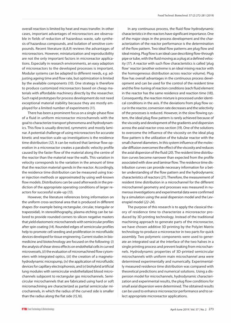
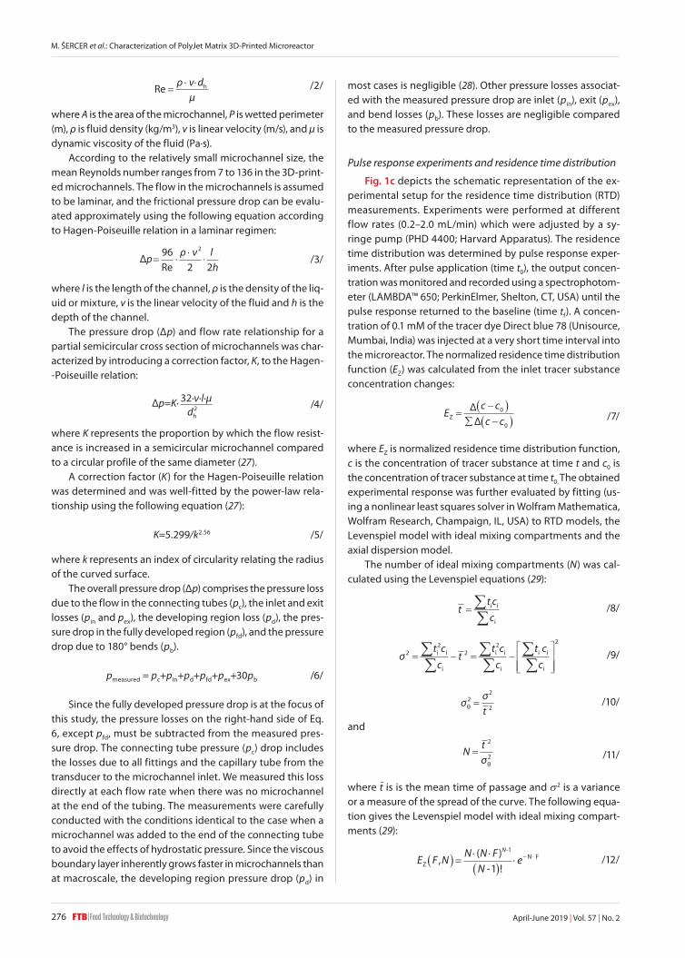
The computer-aided design (CAD) of the microreactor was transformed into a physical model using a 3D printing process PolyJet Matrix, which belongs to the liquid-based processes where a material jetting principle is used for gen-erating each layer of the printed product (Fig. 1). This means that the building (as well as the support) materials are jetted
in liquid state onto the building platform (and then on the previous layer) by a printing head with nozzles and cured by a UV lamp. In the first step, the photosensitive polymer resin was jetted on the building platform and immediately cured by UV light. After curing the first layer, the building platform was lowered for new layer thickness (in this case for 16 µm) and the process was repeated until the microreactor was finished (Fig. 1a (25)). The supplementary material was used to support the building material during the short time
Fig. 1. Graphic presentation of: a) PolyJet Matrix process principles (25), b) left: microreactor half – computer-aided design model, and right: microscopic image of microchannels, and c) a photograph of the microreactor system and schematic representation of the experimental setup for the measurements of pressure drop and residence time distribution
a) b)
c)
Food Technol. Biotechnol. 57 (2) 272-281 (2019)
275April-June 2019 | Vol. 57 | No. 2
between jetting and curing and to support structures that would otherwise be printed ’on the air‘ (e.g. structures that are not supported by a previous layer of a building material). For the hydrodynamic characterization, a microreactor with rather small dimensions (geometric area 60 mm×60 mm) with microchannels integrated into one-half of the microreactor has been developed. The diameter of microchannels was 0.66 mm with a half-circle cross section. The total length of the mi-crochannels was 600 mm (Fig. 1b left). As the channels were designed on the contact surface of two microreactor halves, the area around the microchannel had to be appropriately sealed by a second polymer, a rubber-like acrylic resin Tan-goBlackPlus™ FLX980 (Stratasys, Eden Prairie, MN, USA). The microscopy image of microchannels (Fig. 1b right) was photo-graphed using stereomicroscope Leica MZ6 (Leica Microsys-tems, Wetzlar, Germany) with magnification 7.88×. The gen-eral mechanical and thermal properties of VeroClear RGD810 (Stratasys) and TangoBlackPlus FLX980 (Stratasys) materials used to build the microreactor are given in Table 1 (25).
performed. From the obtained values of the parameters of surface roughness, the arithmetic mean (x–), standard devia-tion (σ) and range (R=Max–Min) were determined.
Table 2. Surface roughness
Measurement profile No. Ra/µm Rz/µm
a1 0.495 2.172
2 0.565 2.843
b3 0.471 2.222
4 0.394 2.296
c5 0.652 2.168
6 0.649 2.209
d7 0.632 2.370
8 0.673 2.600
x̄ 0.566 2.360
S 0.103 0.242
R 0.279 0.675
Experimental setup
A schematic diagram of the experimental setup is shown in Fig. 1c. It consists of the Y-shaped front section with two converging microchannels with a semicircular cross-section-al area and a similarly shaped main channel, syringe pumps (model AL-4000; World Precision Instrument (WPI), Hitchin, Hertfordshire, UK, and model PHD 4400; Harvard Apparatus, Holliston, MA, USA) and a control and data acquisition ASIA sys-tem (Syrris, Royston, UK). The syringe pump uses two syringe tubes to drive the deionised water and tracer into different in-let chambers. The two liquid streams meet at the intersection of the two front channels and the main channel. The mixture output from the main channel is drained to a flow-through cuvette placed in a spectrophotometer, which allowed the determination of the residence time distribution as the func-tion of flow rate. To measure the pressure drop, a gauge pres-sure transmitter Huba 692 (Huba Control, Würenlos, Switzer-land) was fixed at the channel inlet with the T-junctions. The measured pressure was then monitored and recorded with a computerized data acquisition system (National Instruments, Austin, TX, USA). The flow was considered to have reached a steady state when the readings of the pressure drop did not change with time. The present study employs deionised wa-ter as the working fluid. The single-phase flow of deionised water in the 3D-printed microreactor was studied, and the volumetric flow rate of water (Q) was controlled in a range 0.2–2.0 mL/min. Linear velocity, v, was determined as the quo-tient of the flow rate and the channel cross-section area.
Determination of hydraulic diameter, Reynolds number and pressure drop in the microchannels
The hydraulic diameter (dh, in m) of microchannel was cal-culated to determine Reynolds number (Re) using the equa-tions below (26):
dA
Ph =×4
/1/
and
Table 1. General mechanical and thermal properties of VeroClear and TangoBlackPlus materials (25)
VeroClear RGD810 Unit Metric Unit Imperial
Tensile strength MPa 50–65 psi 7250–9450
Elongation at break % 10–25 % 10–25
Modulus of elasticity MPa 2000–3000 psi 290 000–435 000
Flexural strength MPa 75–110 psi 11 000–16 000
Flexural modulus MPa 2200–3200 psi 320 000–465 000
HDT, °C at 0.45 MPa °C 45–50 °F 113–122
HDT, °C at 1.82 MPa °C 45–50 °F 113–122
Izod notched impact J/m 20–30 ftlb/inch 0.375–0.562
Water absorption % 1.1–1.5 % 1.1–1.5
Tg °C 52–54 °F 126–129
Shore hardness (D) Scale D 83–86 Scale D 83–86
Rockwell hardness Scale M 73–76 Scale M 73–76
Polymerized density g/cm3 1.18–1.19 –
Ash content % 0.02–0.06 % 0.02–0.06
TangoBlackPlus FLX980 Unit Metric Unit Imperial
Tensile strength MPa 0.8–1.5 psi 115–220
Elongation at break % 170–220 % 170–220
Compressive set % 4–5 % 4–5
Shore hardness (A) Scale A 26–28 Scale A 26–28
Tensile tear resistance kg/cm 2–4 lb/in 18–22
Polymerized density g/cm3 1.12–1.13
Surface roughness was tested by a contact method us-ing the Perthometer S8P measuring instrument (Mahr GmbH, Göttingen, Germany) with Gauss filter at the cut-off wave-length λc=0.8 mm, reference length ln=4 mm and spike ra-dius r=5 µm. The value of roughness is usually measured regarding the mean reference line of the profile of uneven areas, m, which divides the profile so that within the mea-surement length, ln, the value of all the squares of profile de-viation from that line is minimal. The surface roughness is determined perpendicularly to the direction of production (Table 2). Measurement was performed at the four roughness profiles. In the area of each profile, two measurements were
M. ŠERCER et al.: Characterization of PolyJet Matrix 3D-Printed Microreactor
April-June 2019 | Vol. 57 | No. 2276
Reρ ν
µdh /2/
where A is the area of the microchannel, P is wetted perimeter (m), ρ is fluid density (kg/m3), v is linear velocity (m/s), and µ is dynamic viscosity of the fluid (Pa·s).
According to the relatively small microchannel size, the mean Reynolds number ranges from 7 to 136 in the 3D-print-ed microchannels. The flow in the microchannels is assumed to be laminar, and the frictional pressure drop can be evalu-ated approximately using the following equation according to Hagen-Poiseuille relation in a laminar regimen:
∆plh
962 2
2
Reρ ν
/3/
where l is the length of the channel, ρ is the density of the liq-uid or mixture, v is the linear velocity of the fluid and h is the depth of the channel.
The pressure drop (Δp) and flow rate relationship for a partial semicircular cross section of microchannels was char-acterized by introducing a correction factor, K, to the Hagen--Poiseuille relation:
∆p=K·d
32·ν·l·μ2h
/4/
where K represents the proportion by which the flow resist-ance is increased in a semicircular microchannel compared to a circular profile of the same diameter (27).
A correction factor (K) for the Hagen-Poiseuille relation was determined and was well-fitted by the power-law rela-tionship using the following equation (27):
K=5.299/k2.56 /5/
where k represents an index of circularity relating the radius of the curved surface.
The overall pressure drop (Δp) comprises the pressure loss due to the flow in the connecting tubes (pc), the inlet and exit losses (pin and pex), the developing region loss (pd), the pres-sure drop in the fully developed region (pfd), and the pressure drop due to 180° bends (pb).
pmeasured = pc+pin+pd+pfd+pex+30pb /6/
Since the fully developed pressure drop is at the focus of this study, the pressure losses on the right-hand side of Eq. 6, except pfd, must be subtracted from the measured pres-sure drop. The connecting tube pressure (pc) drop includes the losses due to all fittings and the capillary tube from the transducer to the microchannel inlet. We measured this loss directly at each flow rate when there was no microchannel at the end of the tubing. The measurements were carefully conducted with the conditions identical to the case when a microchannel was added to the end of the connecting tube to avoid the effects of hydrostatic pressure. Since the viscous boundary layer inherently grows faster in microchannels than at macroscale, the developing region pressure drop (pd) in
most cases is negligible (28). Other pressure losses associat-ed with the measured pressure drop are inlet (pin), exit (pex), and bend losses (pb). These losses are negligible compared to the measured pressure drop.
Pulse response experiments and residence time distribution
Fig. 1c depicts the schematic representation of the ex-perimental setup for the residence time distribution (RTD) measurements. Experiments were performed at different flow rates (0.2–2.0 mL/min) which were adjusted by a sy-ringe pump (PHD 4400; Harvard Apparatus). The residence time distribution was determined by pulse response exper-iments. After pulse application (time t0), the output concen-tration was monitored and recorded using a spectrophotom-eter (LAMBDA™ 650; PerkinElmer, Shelton, CT, USA) until the pulse response returned to the baseline (time tf). A concen-tration of 0.1 mM of the tracer dye Direct blue 78 (Unisource, Mumbai, India) was injected at a very short time interval into the microreactor. The normalized residence time distribution function (EZ) was calculated from the inlet tracer substance concentration changes:
Ec c
c cZ0
0
∆∆ /7/
where EZ is normalized residence time distribution function, c is the concentration of tracer substance at time t and c0 is the concentration of tracer substance at time t0. The obtained experimental response was further evaluated by fitting (us-ing a nonlinear least squares solver in Wolfram Mathematica, Wolfram Research, Champaign, IL, USA) to RTD models, the Levenspiel model with ideal mixing compartments and the axial dispersion model.
The number of ideal mixing compartments (N) was cal-culated using the Levenspiel equations (29):
tt c
c= åå
i i
i
/8/
σ22
22 2
t cc
tt c
ct cc
i i
i
i i
i
i i
i
/9/
σσ
θ2
2
2=t
/10/
and
Nt=
2
2σθ /11/
where t̄ is is the mean time of passage and s2 is a variance or a measure of the spread of the curve. The following equa-tion gives the Levenspiel model with ideal mixing compart-ments (29):
E F NN N F
Ne
N
ZN F,
( )- !
-
( ) = × ×( )
× ×1
1- /12/
Food Technol. Biotechnol. 57 (2) 272-281 (2019)
277April-June 2019 | Vol. 57 | No. 2
The error (En) between the experiment and the simula-tion was determined by calculating the global minimum of variance between the experimental and simulated variables:
En
E E
Ei
i n
nu
Zi
Z simi
Zi
u
=-
=
=
å1
1
2( ),exp ,
,exp
/13/
Numerical simulations were performed using the Wolf-ram Mathematica software (Wolfram Research).
Axial dispersion model
The mass flow due to dispersion can be described by Fick’s law:
J Dc
z= - ×ax
dd /14/
According to the axial dispersion model (29), the main micro-reactor parameters are the axial diffusion coefficient (Dax) and Bodenstein number (Bo):
Boax
= ×v
DI /15/
The Bodenstein number characterizes the ratio between the convection and the axial diffusion in a tube of length l where a fluid flows at a flow velocity v. The axial diffusion is calcu-lated using the following expression (30):
D D d
Dax m h
mν νvχ
2
/16/
where χ is a coefficient equal to 192 and Dm is the molecular diffusion constant equal to 10–8 m2/s. Bo thus varies with the velocity and its optimum can be calculated as:
ν
Dfor ν= D
dax max
m
h
χ /17/
RESULTS AND DISCUSSION
Benefits of the 3D-printed microreactor
In order to assure visible control of the occurrences in-side the microreactor, the transparent acrylic resin VeroClear RGD810 with transparency similar to polymethylmethacry-late (PMMA or acrylic glass) was used to build the microreac-tor (25). The PolyJet Matrix process enables, by a combination of two different building materials, the generation of up to 14 different so-called Digital Materials. As the microreactor has to be sealed on the contact surface of both microreactor halves, for the second material, the rubber-like acrylic res-in TangoBlackPlus FLX980 was used (Table 1 (25)). The hard-ness of this material is in the range of 26 to 28 Shore A, which offers a good sealing behaviour at the contact surface with another microreactor half. The seal was printed as a coating along the whole outside surface of the second microreactor half that did not contain microchannels, thus enabling good sealing across the whole contact surface and avoiding the risk
of separation of the seal. All surfaces of the flow system in the microreactor were printed with VeroClear RGD810, which has better mechanical properties and higher chemical resistance than the TangoBlackPlus FLX980 material. This results in ther-mal stability of up to 50 °C, which was considered to be ap-propriate for this application.
The whole process of 3D printing was finished within 3 h, which is significantly shorter than the traditional approach with metal machining. In a traditional production process, such small channels could be produced only by an electro-erosion process, which is time-consuming and costly. More-over, in the case of metal machining, the microreactor would not be transparent. With PolyJet technology it is possible to create even smaller channels (down to 0.25 mm in diame-ter) or to create channels that are not straight but proceed in a zig-zag manner, which additionally enlarges the channel length and increases the mixing of fluids. These possibilities promote 3D printing technology as an excellent solution to develop and produce microreactors.
Main parameters for determination of surface roughness were mean arithmetic deviation of the profile, Ra, and mean height of unevenness, Rz (Table 2). According to previous re-search of PolyJet products, roughness is about 1 µm (31), but in this case, due to contact with the other half of the micro-reactor, the contact surface was made ‘glossy’ with the fin-ishing parameters on the PolyJet machine, thus reducing the roughness to Ra=0.566 µm.
Optimal flow pattern for 3D-printed microreactor
This research focused on the characterization and op-timization of the flow patterns in the microchannels. This was done by procedures developed for one-phase systems. Therefore, the Reynolds number for the one-phase system was calculated, and it was in the range of 7–136 with the cor-responding flow rates of 0.2–2.0 mL/min. According to the literature (26,27), the flow in tubular channels is laminar at Reynolds numbers below 2100 and turbulent above this val-ue. However, some recent publications doubt the applica-tion of this theory in the case of microchannels. The relatively high roughness of microchannels might reduce the critical Reynolds number for the transition from laminar to turbulent flow. Peng et al. (32) detected transitions to turbulence flow at Reynolds numbers between 200 and 700, with the transition value depending on the hydraulic diameter. This was, howev-er, contradicted by Pfund et al. (33). Transitions to turbulence were observed with flow visualization and the flow was lami-nar for Re<1700 in the 263 mm deep channel. Further Re num-ber increase was related to the turbulent flow. In any case, the Reynolds numbers achieved in our microchannel are much lower than the critical Reynolds number. Therefore, laminar flow can be assumed in the entire application range of our microsystem. As a consequence, mixing occurs only by dif-fusion and not by convection as in the case of turbulent flow.
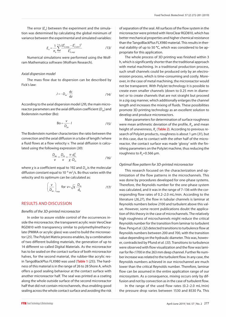
In the range of the used flow rates (0.2–2.0 mL/min) the pressure drop varies between 1530 and 8530 Pa. This
M. ŠERCER et al.: Characterization of PolyJet Matrix 3D-Printed Microreactor
April-June 2019 | Vol. 57 | No. 2278
corresponds to a ∆p/ltot ranging between 25.50 and 142.16 kPa/m. Soft and hard micromachining techniques used to de-velop microfluidic devices can yield microchannels of many different cross-sectional profiles. For semicircular microchan-nels, these techniques often produce only partial semicircular cross-sections. Fig. 2 shows the calculated pressure drop us-ing Eqs. 3 and 4 from the corresponding combination of lin-ear velocity and microchannel length. The variance between experimental results and the model was EN=18.52·10–3 (for Ha-gen-Poiseuille relation; Eq. 3) and EN=0.87·10–3 (for Hagen-Po-iseuille relation with a correction factor; Eq. 4). Eq. 4 presents a better agreement between the experimental results and simulated model than Eq. 3. Using regression analyses, a cor-rection factor K was determined for 3D-printed microreactor. The correction factor K represents the proportion by which the flow resistance (Δp/Q) is increased in a partial semicircular cross section microchannel compared to a circular duct of di-ameter, D. The correction factor computed from simulations was 7.45. The flow correction factor increased by decreased k value (k=1 for a semicircular microchannel) (27).
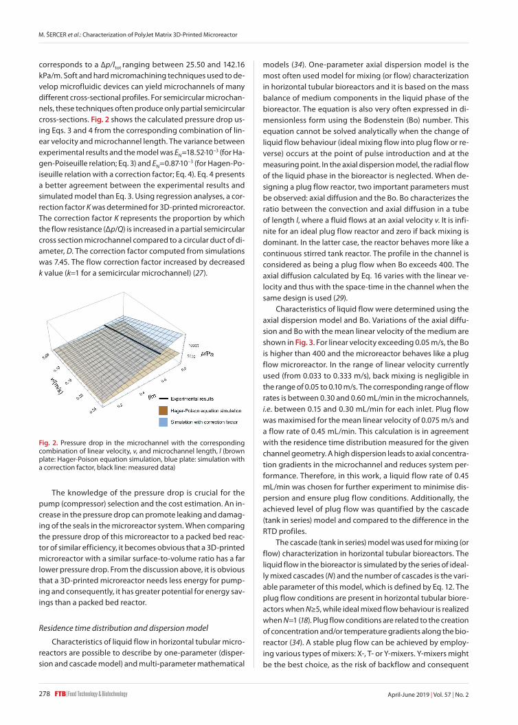
models (34). One-parameter axial dispersion model is the most often used model for mixing (or flow) characterization in horizontal tubular bioreactors and it is based on the mass balance of medium components in the liquid phase of the bioreactor. The equation is also very often expressed in di-mensionless form using the Bodenstein (Bo) number. This equation cannot be solved analytically when the change of liquid flow behaviour (ideal mixing flow into plug flow or re-verse) occurs at the point of pulse introduction and at the measuring point. In the axial dispersion model, the radial flow of the liquid phase in the bioreactor is neglected. When de-signing a plug flow reactor, two important parameters must be observed: axial diffusion and the Bo. Bo characterizes the ratio between the convection and axial diffusion in a tube of length l, where a fluid flows at an axial velocity v. It is infi-nite for an ideal plug flow reactor and zero if back mixing is dominant. In the latter case, the reactor behaves more like a continuous stirred tank reactor. The profile in the channel is considered as being a plug flow when Bo exceeds 400. The axial diffusion calculated by Eq. 16 varies with the linear ve-locity and thus with the space-time in the channel when the same design is used (29).
Characteristics of liquid flow were determined using the axial dispersion model and Bo. Variations of the axial diffu-sion and Bo with the mean linear velocity of the medium are shown in Fig. 3. For linear velocity exceeding 0.05 m/s, the Bo is higher than 400 and the microreactor behaves like a plug flow microreactor. In the range of linear velocity currently used (from 0.033 to 0.333 m/s), back mixing is negligible in the range of 0.05 to 0.10 m/s. The corresponding range of flow rates is between 0.30 and 0.60 mL/min in the microchannels, i.e. between 0.15 and 0.30 mL/min for each inlet. Plug flow was maximised for the mean linear velocity of 0.075 m/s and a flow rate of 0.45 mL/min. This calculation is in agreement with the residence time distribution measured for the given channel geometry. A high dispersion leads to axial concentra-tion gradients in the microchannel and reduces system per-formance. Therefore, in this work, a liquid flow rate of 0.45 mL/min was chosen for further experiment to minimise dis-persion and ensure plug flow conditions. Additionally, the achieved level of plug flow was quantified by the cascade (tank in series) model and compared to the difference in the RTD profiles.
The cascade (tank in series) model was used for mixing (or flow) characterization in horizontal tubular bioreactors. The liquid flow in the bioreactor is simulated by the series of ideal-ly mixed cascades (N) and the number of cascades is the vari-able parameter of this model, which is defined by Eq. 12. The plug flow conditions are present in horizontal tubular biore-actors when N≥5, while ideal mixed flow behaviour is realized when N=1 (18). Plug flow conditions are related to the creation of concentration and/or temperature gradients along the bio-reactor (34). A stable plug flow can be achieved by employ-ing various types of mixers: X-, T- or Y-mixers. Y-mixers might be the best choice, as the risk of backflow and consequent
The knowledge of the pressure drop is crucial for the pump (compressor) selection and the cost estimation. An in-crease in the pressure drop can promote leaking and damag-ing of the seals in the microreactor system. When comparing the pressure drop of this microreactor to a packed bed reac-tor of similar efficiency, it becomes obvious that a 3D-printed microreactor with a similar surface-to-volume ratio has a far lower pressure drop. From the discussion above, it is obvious that a 3D-printed microreactor needs less energy for pump-ing and consequently, it has greater potential for energy sav-ings than a packed bed reactor.
Residence time distribution and dispersion model
Characteristics of liquid flow in horizontal tubular micro-reactors are possible to describe by one-parameter (disper-sion and cascade model) and multi-parameter mathematical
Fig. 2. Pressure drop in the microchannel with the corresponding combination of linear velocity, v, and microchannel length, l (brown plate: Hager-Poison equation simulation, blue plate: simulation with a correction factor, black line: measured data)
Food Technol. Biotechnol. 57 (2) 272-281 (2019)
279April-June 2019 | Vol. 57 | No. 2
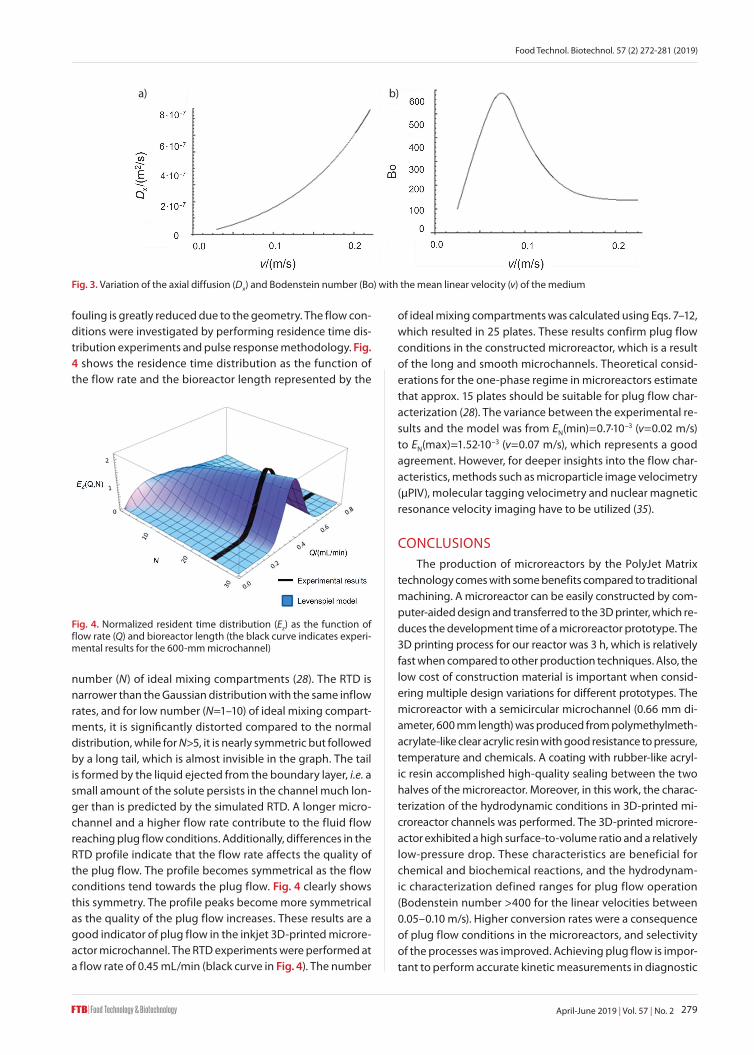
fouling is greatly reduced due to the geometry. The flow con-ditions were investigated by performing residence time dis-tribution experiments and pulse response methodology. Fig. 4 shows the residence time distribution as the function of the flow rate and the bioreactor length represented by the
of ideal mixing compartments was calculated using Eqs. 7–12, which resulted in 25 plates. These results confirm plug flow conditions in the constructed microreactor, which is a result of the long and smooth microchannels. Theoretical consid-erations for the one-phase regime in microreactors estimate that approx. 15 plates should be suitable for plug flow char-acterization (28). The variance between the experimental re-sults and the model was from EN(min)=0.7·10–3 (v=0.02 m/s) to EN(max)=1.52·10–3 (v=0.07 m/s), which represents a good agreement. However, for deeper insights into the flow char-acteristics, methods such as microparticle image velocimetry (µPIV), molecular tagging velocimetry and nuclear magnetic resonance velocity imaging have to be utilized (35).
CONCLUSIONSThe production of microreactors by the PolyJet Matrix
technology comes with some benefits compared to traditional machining. A microreactor can be easily constructed by com-puter-aided design and transferred to the 3D printer, which re-duces the development time of a microreactor prototype. The 3D printing process for our reactor was 3 h, which is relatively fast when compared to other production techniques. Also, the low cost of construction material is important when consid-ering multiple design variations for different prototypes. The microreactor with a semicircular microchannel (0.66 mm di-ameter, 600 mm length) was produced from polymethylmeth-acrylate-like clear acrylic resin with good resistance to pressure, temperature and chemicals. A coating with rubber-like acryl-ic resin accomplished high-quality sealing between the two halves of the microreactor. Moreover, in this work, the charac-terization of the hydrodynamic conditions in 3D-printed mi-croreactor channels was performed. The 3D-printed microre-actor exhibited a high surface-to-volume ratio and a relatively low-pressure drop. These characteristics are beneficial for chemical and biochemical reactions, and the hydrodynam-ic characterization defined ranges for plug flow operation (Bodenstein number >400 for the linear velocities between 0.05–0.10 m/s). Higher conversion rates were a consequence of plug flow conditions in the microreactors, and selectivity of the processes was improved. Achieving plug flow is impor-tant to perform accurate kinetic measurements in diagnostic
Fig. 3. Variation of the axial diffusion (Dx) and Bodenstein number (Bo) with the mean linear velocity (v) of the medium
Fig. 4. Normalized resident time distribution (Ez) as the function of flow rate (Q) and bioreactor length (the black curve indicates experi-mental results for the 600-mm microchannel)
a) b)
number (N) of ideal mixing compartments (28). The RTD is narrower than the Gaussian distribution with the same inflow rates, and for low number (N=1–10) of ideal mixing compart-ments, it is significantly distorted compared to the normal distribution, while for N>5, it is nearly symmetric but followed by a long tail, which is almost invisible in the graph. The tail is formed by the liquid ejected from the boundary layer, i.e. a small amount of the solute persists in the channel much lon-ger than is predicted by the simulated RTD. A longer micro-channel and a higher flow rate contribute to the fluid flow reaching plug flow conditions. Additionally, differences in the RTD profile indicate that the flow rate affects the quality of the plug flow. The profile becomes symmetrical as the flow conditions tend towards the plug flow. Fig. 4 clearly shows this symmetry. The profile peaks become more symmetrical as the quality of the plug flow increases. These results are a good indicator of plug flow in the inkjet 3D-printed microre-actor microchannel. The RTD experiments were performed at a flow rate of 0.45 mL/min (black curve in Fig. 4). The number
M. ŠERCER et al.: Characterization of PolyJet Matrix 3D-Printed Microreactor
April-June 2019 | Vol. 57 | No. 2280
applications, cell culture, drug discovery, organs-on-chips, or even forensic analysis. Therefore, it can be concluded that the PolyJet Matrix technology can be easily used for the produc-tion of microreactors and the obtained hydrodynamic char-acteristics are competitive, which advances the production and application of 3D-printed microreactors.
ACKNOWLEDGEMENTSThis work was financed by the projects UIP-2014-09-
-1534 ’Synthesis and targeted application of metallic nano-particles – STARS‘ and ’9717-Sustainable production of bio-chemicals from waste lignocellulose containing feedstocks‘ funded by the Croatian Science Foundation, IPA III c – Ad-ditive Technologies for the SMEs –AdTecSME, and WTZ HR 12/2016. The authors would like to thank the European Union, Croatian Science Foundation, the Croatian Ministry of Science and Education, and the Austrian Academic Exchange Service (ÖAD) for financial support. Moreover, any opinions, findings and conclusions or recommendations expressed in this ma-terial are those of the authors and do not necessarily reflect the views of the Croatian Science Foundation.
ORCID IDsM. Šercer https://orcid.org/0000-0002-3595-7166T. Rezić https://orcid.org/0000-0001-7290-5202D. Godec https://orcid.org/0000-0003-3449-9850D. Oros https://orcid.org/0000-0002-5357-9058 A. Pilipović https://orcid.org/0000-0003-1330-6458F. Ivušić https://orcid.org/0000-0001-5445-9982I. Rezić https://orcid.org/0000-0002-1531-776XM. Andlar https://orcid.org/0000-0002-8745-7921R. Ludwig https://orcid.org/0000-0002-5058-5874B. Šantek https://orcid.org/0000-0001-9583-534X
REFERENCES 1. Comina G, Suska A, Filippini D. PDMS lab-on-a-chip fabrica-
tion using 3D printed templates. Lab Chip. 2014;14(2):424–30.
https://doi.org/10.1039/C3LC50956G
2. Lobo Júnior EO, Duarte LC, de Paula Braga LE, Gobbi ÂL, Pereira De Jesus D, Tomazelli Coltro WK. High fidelity proto-typing of PDMS electrophoresis microchips using laser-print-ed masters. Microsyst Technol. 2015;21(6):1345–52.
https://doi.org/10.1007/s00542-014-2190-z
3. Glick CC, Srimongkol MT, Schwartz AJ, Zhuang WS, Lin JC, Warren RH, et al. Rapid assembly of multilayer microfluid-ic structures via 3D-printed transfer molding and bond-ing. Microsyst Nanoeng. 2016;2:Article No. 16063.
https://doi.org/10.1038/micronano.2016.63
4. Hwang Y, Paydar OH, Candler RN. 3D printed molds for non-planar PDMS microfluidic channels. Sens Actuators A Phys. 2015;226:137–42.
https://doi.org/10.1016/j.sna.2015.02.028
5. Romao Bineli AR, Gimenez Peres AP, Jardini AL, Filho RM. Direct metal laser sintering (DMLS): Technology for de-sign and construction of microreactors. 6th Brazilian con-ference on manufacturing engineering, 2011 April 11–15, Caixas do Sul, RS, Brazil: Brazilian Society of Mechanical Sciences and Engineering (ABCM); 2011. Available online: http://www.alvarestech.com/temp/cobef2011/grima.ufsc.br/cobef2011/media/trabalhos/COF11-0502.pdf.
6. Capel AJ, Edmondson S, Christie SDR, Goodridge RD, Bibb RJ, Thurstans M. Design and additive manufacture for flow chemistry. Lab Chip. 2013;13(23):4583–90.
https://doi.org/10.1039/C3LC50844G
7. Thomas MS, Millare B, Clift JM. Print-and-peel fabrication for microfluidics: What’s in it for biomedical applications? Ann Biomed Eng. 2009;38(1):21–32.
https://doi.org/10.1007/s10439-009-9831-x
8. Hartman RL, McMullen JP, Jensen KF. Deciding whether to go with the flow: Evaluating the merits of flow reactors for synthesis. Angew Chem Int Ed Engl. 2011;50(33):7502–19.
https://doi.org/10.1002/anie.201004637
9. Wohlgemuth R, Plazl I, Žnidaršič-Plazl P, Gernaey KV, Woodley JM. Microscale technology and biocatalytic processes: Opportunities and challenges for synthesis. Trends Biotechnol. 2015;33(5):302–14.
https://doi.org/10.1016/j.tibtech.2015.02.010
10. Yuen PK, Goral VN. Low-cost rapid prototyping of flexible microfluidic devices using a desktop digital craft cutter. Lab Chip. 2010;10(3):384–87.
https://doi.org/10.1039/B918089C
11. Wu SY, Yang C, Hsu W. 3D-printed microelectronics for in-tegrated circuitry and passive wireless sensors. Microsyst Nanoeng. 2015;1:Article No. 15013.
https://doi.org/10.1038/micronano.2015.13
12. Bolivar JM, Krämer CEM, Ungerböck B, Mayr T, Nidetzky B. Development of a fully integrated falling film microre-actor for gas-liquid-solid biotransformation with surface Immobilized O2-dependent enzyme. Biotechnol Bioeng. 2016;113(9):1862–72.
https://doi.org/10.1002/bit.25969
13. Au AK, Huynh W, Horowitz LF, Folch A. 3D-printed micro-fluidics. Angew Chem Int Ed. 2016;55(12):3862–81.
https://doi.org/10.1002/anie.201504382
14. Bartlett NW, Wood RJ. Comparative analysis of fabrication methods for achieving rounded microchannels. PDMS. J Micromech Microeng. 2016;26(11):115013.
https://doi.org/10.1088/0960-1317/26/11/115013
15. Federspiel WJ, Valenti I. On laminar flow in microfabricated channels with partial semi-circular profiles. Open J Appl Sci. 2012;2(1):28–34.
https://doi.org/10.4236/ojapps.2012.21003
16. Walczak R, Adamski K. Inkjet 3D printing of microfluidic structures – On the selection of the printer towards printing
Food Technol. Biotechnol. 57 (2) 272-281 (2019)
281April-June 2019 | Vol. 57 | No. 2
your own microfluidic chips. J Micromech Microeng. 2015; 25(8):085013.
https://doi.org/10.1088/0960-1317/25/8/085013
17. Gobert SRL, Kuhn S, Braeken L, Thomassen LCJ. Character-ization of milli- and microflow reactors: Mixing efficiency and residence time distribution. Org Process Res Dev. 2017; 21(4):531–42.
https://doi.org/10.1021/acs.oprd.6b00359
18. Hornung CH, Mackley MR. The measurement and charac-terisation of residence time distributions for laminar liquid flow in plastic microcapillary arrays. Chem Eng Sci. 2009; 64(17):3889–902.
https://doi.org/10.1016/j.ces.2009.05.033
19. Nagy KD, Shen B, Jamison TF, Jensen KF. Mixing and disper-sion in small-scale flow systems. Org Process Res Dev. 2012; 16(5):976–81.
https://doi.org/10.1021/op200349f
20. Saber M, Pham-Huu C, Edouard D. Axial dispersion based on the residence time distribution curves in a millireactor filled with b-SiC foam catalyst. Ind Eng Chem Res. 2012;51(46): 15011–7.
https://doi.org/10.1021/ie3017829
21. Chen GG, Luo GS, Li SW, Xu JH, Wang JD. Experimental ap-proaches for understanding mixing performance of a mini-reactor. AIChE J. 2005;51(11): 2923–9.
https://doi.org/10.1002/aic.10539
22. Trachsel F, Günther A, Khan S, Jensen KF. Measurement of residence time distribution in microfluidic systems. Chem Eng Sci. 2005;60(21):5729–37.
https://doi.org/10.1016/j.ces.2005.04.039
23. Kreutzer MT, Günther A, Jensen KF. Sample dispersion for segmented flow in microchannels with rectangular cross section. Anal Chem. 2008;80(5):1558–67.
https://doi.org/10.1021/ac702143r
24. Adeosun JT, Lawal A. Numerical and experimental studies of mixing characteristics in a T-junction microchannel us-ing residence-time distribution. Chem Eng Sci. 2009;64(10): 2422–32.
https://doi.org/10.1016/j.ces.2009.02.013
25. Stratasys Ltd., Eden Prairie, MN, USA. Available from:
http://www.stratasys.com/materials/polyjet. Accessed 17.11.2016.
26. Qu W, Mudawar I. Experimental and numerical study of pres-sure drop and heat transfer in a single-phase micro-channel heat sink. Int J Heat Mass Transf. 2002;45(12):2549–65.
https://doi.org/10.1016/S0017-9310(01)00337-4
27. Federspiel WJ, Valenti I. On laminar flow in microfabricated channels with partial semi-circular profiles. Open J Appl Sci. 2012;2(1):28–34.
https://doi.org/10.4236/ojapps.2012.21003
28. Akbari M, Sinton D, Bahrami M. Pressure drop in rectangular microchannels as compared with theory based on arbitrary cross section. J Fluids Eng. 2009;131(4):2020–8.
https://doi.org/10.1115/1.3077143
29. Levenspiel O. Chemical reaction engineering. Ind Eng Chem Res. 1999;38(11):4140–3.
https://doi.org/10.1021/ie990488g
30. Kashid MN, Renken A, Kiwi-Minsker L. Microstructured de-vices for chemical processing. Weinheim, Germany: Wiley--VCH; 2015.
31. Pilipović A, Raos P, Šercer M. Experimental analysis of prop-erties of materials for rapid prototyping. Int J Adv Manuf Technol. 2009;40(1-2):105–15.
https://doi.org/10.1007/s00170-007-1310-7
32. Peng XF, Peterson GP, Wang BX. Heat transfer characteristics of water flowing through microchannels. Exp Heat Transfer. 1994;7(4):265–83.
https://doi.org/10.1080/08916159408946485
33. Pfund D, Rector D, Shekarriz A, Popescu A, Welty J. Pressure drop measurements in a microchannel. Aiche J. 2000;46(8): 1496–507.
https://doi.org/10.1002/aic.690460803
34. Šantek B, Ivančić M, Horvat P, Novak S, Marić V. Horizontal tubular bioreactors in biotechnology. Chem Biochem Eng Q. 2006;20(4):389–99.
35. Moser A. Imperfectly mixed biorector systems. In: Moo- -Young M, editor. Comprehensive biotechnology. Oxford, UK: Pergamon Press; 1985. pp. 77.