microrockets for smart dust - · characteristics of different types of chemical rocket propellants...
TRANSCRIPT
Microrockets for Smart Dust
Dana A. Teasdale, Veljko Milanovic, Paul Chang, Kristofer S. J. Pister
Berkeley Sensor and Actuator Center (BSAC)University of California, Berkeley
497 Cory Hall Berkeley, CA 94720
[teasdale,veljko,pcchang,pister]@bsac.eecs.berkeley.edu
1
Abstract
This paper details design and fabrication aspects of millimeter scale solid propellant rock-ets for use as one-time deployment platforms carrying communication-equipped MEMS sensor systems, known as Smart Dust. Each rocket assembly is an integrated system, incorporating a combustion chamber, composite propellant grain, nozzle, igniter, and thermoelectric power con-verter. Solid propellant is advantageous for a millimeter-scale single-use device because of its simple implementation, unlike liquid propellants, which require a more elaborate system of pumps and valves. Therefore, the total system volume and complexity are minimized.
Combustion chambers were fabricated in silicon wafers; however, thermal losses during combustion through a 1.5 mm² cross section of fuel were too high to reliably maintain a burn. Therefore, cylindrical alumina ceramic combustion chambers with thermal conductivities five times lower than silicon are being used, in which combustion through cross sections from 1 to 8
mm2 has been demonstrated. Thrusts of 10 mN to 15 mN have been measured for ceramic rock-ets weighing under 1 g, with specific impulses up to 15 s.
Silicon nozzles integrated with polysilicon igniters and thermopiles for thermal power conversion have been microfabricated in a single process. Fuel ignition by polysilicon heaters suspended on a low-stress nitride (LSN) membrane has been demonstrated. Igniters require less than one watt of power to reach the ignition temperature of HTPB/AP propellant, approximately
600oC. The igniter is suspended for thermal isolation through bulk post-processing by a backside deep reactive ion etch (DRIE). The etched hole beneath the igniter also serves as a nozzle through which high-velocity combustion gases exit the rocket. Thermopiles, which generate voltages pro-portional to hot and cold junction temperature differentials, have been fabricated in the same pro-cess as igniters, and span backside DRIE thermal isolation cavities. With potential temperature differences of hundreds of degrees and a total of 120 thermocouple junctions fabricated on the sil-icon nozzle chip, 0.5 µW of power could feasibly be produced during the microrocket's flight and used to augment the Smart Dust power supply.
2
1. Introduction
From its inception, space exploration has been costly and hazardous due to the high costs
of large, complex spacecraft and sometimes the endangerment of human lives. Trends in space-
related industries are toward the miniaturization of spacecraft and space systems [1]. Decreasing
the size of space systems requires the miniaturization of environmental monitoring components
and propulsion systems.
Advances in the fields of digital circuitry, wireless communications and microelectrome-
chanical systems (MEMS) converge in the development of tiny, low-power, low-cost, autono-
mous sensor nodes known a Smart Dust, an ongoing research project at the Berkeley Sensor and
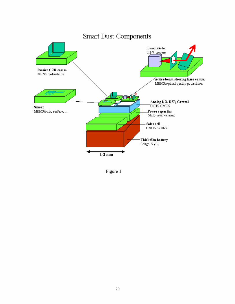
Actuator Center [2]. Each Smart Dust mote is designed with its own suite of MEMS sensors,
wireless communications, computing hardware, and a power supply, all within a few cubic milli-
meters (Figure 1). So far, advances in line-of-sight optical communication using corner cube
reflectors (CCR) [3] as passive transmitter and large DC deflection 2-DOF micromirros for beam
steering have been reported [4]. Additionally, preliminary platforms designed to test incoming
optical signal decoding, generate simulated sensor data with a pseudorandom number generator
and drive a CCR have been designed and fabricated in a 0.25 µm CMOS process [5]. One impor-
tant application for Smart Dust is monitoring environments in which data collection through
wired networks or by humans may be difficult, such as outer space.
A micropropulsion system capable of flight with milligram payloads could be used to dis-
tribute Smart Dust motes from a base station on earth or in space. Multiple hop communication
between Smart Dust motes within approximately a kilometer radius of each other would then
allow data at remote sites, or even around an entire planet, to be collected at a central station, such
as a satellite (Figure 2). Smart Dust deployment by microrockets would expand the area and sen-
3
sor density through which monitoring could be performed.
Miniaturizing a rocket system presents unique challenges:
• Propellant - A high energy density propellant that combusts though small cross sections and
has chemical reaction rates fast enough that combustion is completed during the propellant’s
residence time in the combustion chamber is required.
• Assembly and Fabrication - Combustion chambers must provide thermal insulation to burning
propellant and sustain high internal pressures. The use of microfabrication techniques is
desirable due to batch fabrication, low cost, and integration with several micromachined com-
ponents.
• Ignition - Adequate energy must be supplied by a microfabricated structure to ignite the pro-
pellant.
Previous work toward the development of low-thrust micropropulsion systems with nano-
satellite and microsatellite station-keeping and maneuvering applications has been done. Janson
et al. [6] discuss microfabricated cold gas thrusters, digital thruster arrays, resistojets, and field
ion engines. Thrust-producing devices have been fabricated through various micromachining
processes with measured thrust up to 1 mN for cold gas thrusters, and impulses in the 0.09 mN-s
range for the digital thrusters. Other solid propellant microthrusters were developed by Rossi et
al [7], with measured thrusts of up to 1 g. While effectively producing the thrust levels required
for some microsatellite and nanosatellite positioning applications, none of these systems have
been designed specifically for flight.
This paper describes the design and fabrication of a microrocket designed for one-time
deployment of Smart Dust motes through rocket flight. The microrocket system presented inte-
grates rocket propellant, a ceramic combustion chamber, silicon micromachined nozzle, polysili-
4
con igniter, and thermal power converters. Micromachining techniques enable the fabrication of
the polysilicon igniter and thermopiles for thermal power conversion to be completed in the same
process, all on a silicon substrate backside etched to become the rocket nozzle.
2. Propellant
Despite demonstrated rocket propulsion by methods including nuclear thermal rockets,
ion propulsion, and hall effect thrusters, chemical rocket engines remain the most commonly used
[8]. Chemical reactants are second only to nuclear fuels in terms of energy density, which is on
the order of 3.5x10⁷ J/L for kerosene [9]. Chemical propellants have also been widely researched
and used reliably in applications ranging from booster rockets for the space shuttle to numerous
hobby rockets.
Characteristics of different types of chemical rocket propellants were investigated to
choose the most appropriate fuel for a microrocket. The the two most common types of chemical
propellants are solid and liquid (Figure 3). In solid propellants, the fuel and oxidizer are both
present in solid form, can be stored at room temperature, and are easy to use without special oper-
ating and handling equipment. Liquid propellants are composed of liquid fuels and oxidizers that
are stored separately and mixed at the time of combustion. They require systems for storage and
usage, including pumps, valves and sometimes cryogenic storage tanks. For some applications,
however, the complexity of handling liquid propellants is warranted because they often have
higher specific impulses than solids, and combustion can be readily throttled or stopped alto-
gether. Specific Impulse describes the total force integrated over burning time per unit weight of
the propellant, and can be estimated by Ft/mg, where F is thrust [N], t is time [s], m is propellant
mass [kg], and g is the gravitational constant [ms-2].
Special consideration in the development of a microrocket must be given to fuel energy
5
density, specific impulse, flammability limits, fabrication capabilities, and system complexity. To
achieve the smallest overall structure while preserving design simplicity and relatively high spe-
cific impulse, a solid, composite fuel with ammonium perchlorate oxidizer (AP) was chosen. The
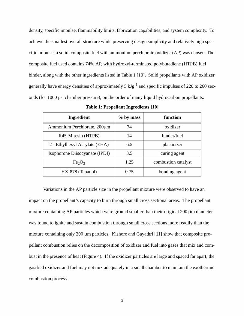
composite fuel used contains 74% AP, with hydroxyl-terminated polybutadiene (HTPB) fuel
binder, along with the other ingredients listed in Table 1 [10]. Solid propellants with AP oxidizer
generally have energy densities of approximately 5 kJg-1 and specific impulses of 220 to 260 sec-
onds (for 1000 psi chamber pressure), on the order of many liquid hydrocarbon propellants.
Variations in the AP particle size in the propellant mixture were observed to have an
impact on the propellant’s capacity to burn through small cross sectional areas. The propellant
mixture containing AP particles which were ground smaller than their original 200 µm diameter
was found to ignite and sustain combustion through small cross sections more readily than the
mixture containing only 200 µm particles. Kishore and Gayathri [11] show that composite pro-
pellant combustion relies on the decomposition of oxidizer and fuel into gases that mix and com-
bust in the presence of heat (Figure 4). If the oxidizer particles are large and spaced far apart, the
gasified oxidizer and fuel may not mix adequately in a small chamber to maintain the exothermic
combustion process.
Table 1: Propellant Ingredients [10]
Ingredient % by mass function
Ammonium Perchlorate, 200µm 74 oxidizer
R45-M resin (HTPB) 14 binder/fuel
2 - Ethylhexyl Acrylate (EHA) 6.5 plasticizer
Isophorone Diisocyanate (IPDI) 3.5 curing agent
Fe2O3 1.25 combustion catalyst
HX-878 (Tepanol) 0.75 bonding agent
6
Adding aluminum (Al) particles to composite propellants is often done to increase the
burn rate, flame temperature, or energy density of the fuel. Al was added to the HTPB/AP com-
posite fuel, and ignited by a thin wire filament inside a a 3x4x1.5 mm ceramic combustion cham-
ber. The added Al did result in an increase in burn rate; however, Al particles were visibly
combusting after exiting the chamber, and were found to clog sub-millimeter nozzles. This agrees
with Sigman et al [12], that during combustion Al particles tend to agglomerate at the burning
surface and exit the combustion chamber without fully burning. A comparison between combus-
tion flames for HTPB/AP and HTPB/AP/Al in 3x4x1.5 mm ceramic combustion chambers are
shown in Figure 5a,b. This result is an indication of how scaling can affect rocket performance;
the residence time of combustion species in the combustion chamber must be longer than chemi-
cal combustion reaction rates. HTBP/AP fuel mixture without Al was used for all subsequent
testing.
3. Rocket Assembly & Fabrication
The rocket assembly has two basic components: a combustion chamber and a nozzle. The
combustion chamber houses the solid propellant, while the nozzle is a constriction at the combus-
tion chamber exit that allows hot combustion gases to accelerate as they exit the rocket, thereby
increasing thrust. Igniters and power-converting thermopiles are fabricated on the same silicon
substrate that the nozzle is etched into, and will be discussed in more detail in subsequent sec-
tions.
Investigations of combustion chambers and nozzles made of various materials were con-
ducted. 2-D combustion chambers were fabricated in copper, aluminum, brass, carbon steel, and
stainless steel by wire electrical discharge machining (EDM), and in ceramic by conventional
machining. Similar chambers were also fabricated in silicon using deep reactive ion etch (DRIE).
7
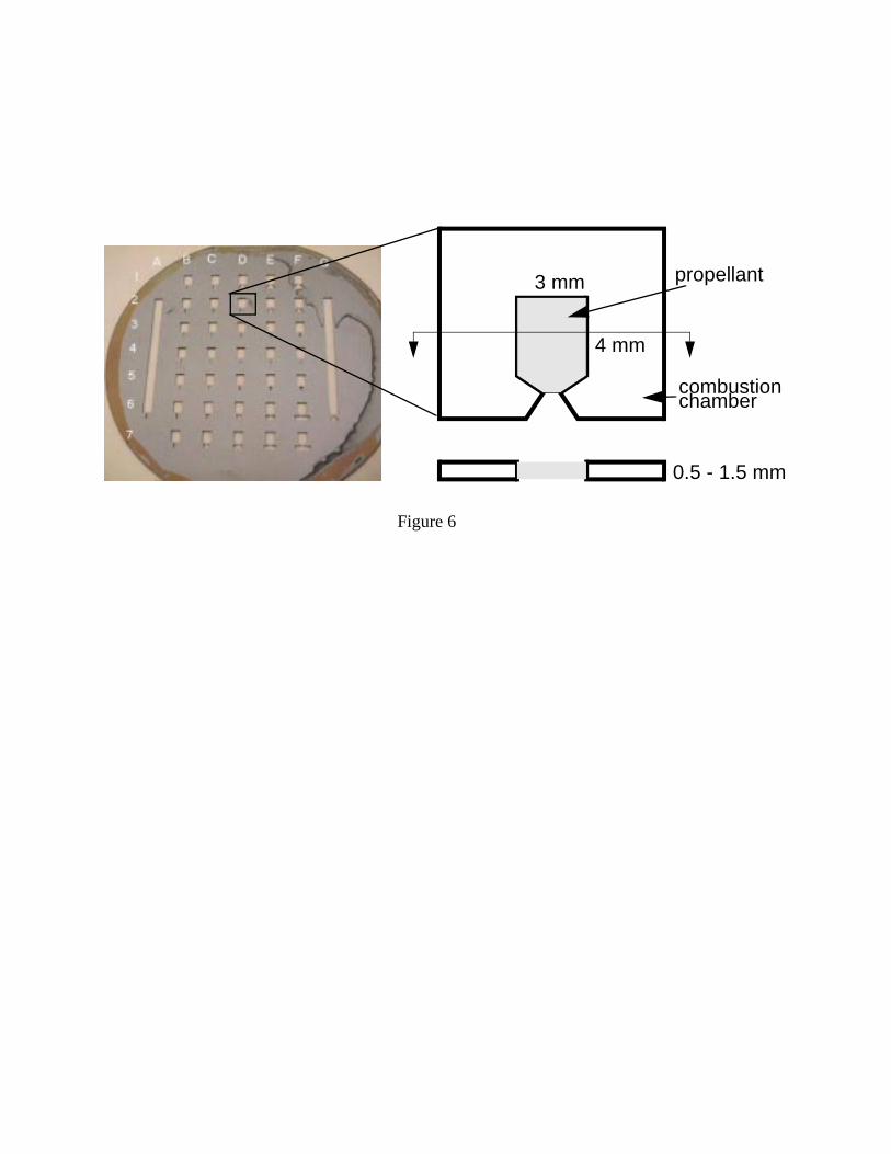
In this process, wafers Figure 6 of silicon combustion chambers were fabricated with a single
photolithography step followed by DRIE through the wafer. Each 2-D chamber had a cross sec-
tion similar to the design shown in Figure 6.
Each rocket system is assembled by packing uncured propellant into the ceramic combus-
tion chamber, allowing the propellant to cure, and bonding the propellant-filled combustion
chamber and the nozzle die together with high-temperature epoxy. The open end of the combus-
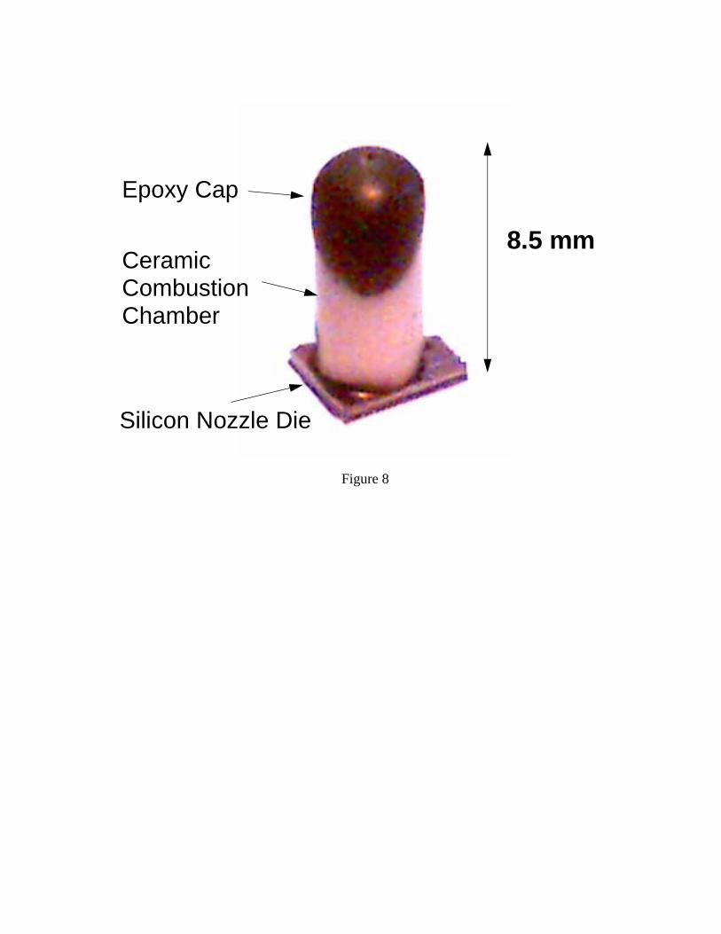
tion chamber is also sealed with epoxy. Figure 7 shows a design rendering of the rocket assembly,
with a detail of the nozzle, and Figure 8 shows the assembled microrocket.
3.1 Combustion Chamber
In preliminary tests, the combustion chambers were filled with hydroxyl-terminated
polybutadiene (HTPB)/ammonium perchlorate (AP) composite fuel and sealed by epoxying glass
plates to the chambers. Ignition was achieved by heating a thin wire filament in contact with the
fuel at the nozzle opening. Testing showed that at room temperature, combustion was difficult to
sustain through the entire length of the 2-D combustion chamber, with the only repeatable sus-
tained burn occurring in the ceramic combustion chambers. This result suggested the need to
choose a combustion chamber material with low thermal conductivity, since heat loss through the
chamber walls removed enough energy from the burning fuel to quench combustion in the silicon
and metal chambers. Additionally, the 1.5 mm glass covers to the chambers were found to break
during combustion due to the high pressures generated in the combustion chamber, indicating the
need for stronger chamber walls.
An alumina ceramic cylindrical combustion chamber design addresses the needs of ther-
mal insulation and strength. Alumina ceramic has a thermal conductivity of 30 W/m K, five times
lower than the thermal conductivity of silicon. Additionally, the cylindrical shape reduces the
8
surface area by 13% compared to a 1.5 mm thick rectangular chamber having the same length and
volume. This also serves to reduce the overall volume occupied by the chamber since less wall
surface is required, thus reducing the mass of the rocket. The cylindrical chamber also has a
structural advantage over the flat, rectangular chamber since it is able to resist bending, which the
walls of the rectangular chamber are prone to.
Overall, alumina ceramic cylindrical combustion chambers offer low thermal conductiv-
ity, decreased surface area, decreased total volume, and increased structural integrity when com-
pared to 2-D silicon and metal chambers. The main disadvantage to alumina ceramic cylinders is
that they are not microfabricated, and must be machined separately. A more exhaustive investiga-
tion of materials and chamber geometries is required to minimize combustion chamber mass, vol-
ume and thermal conductivity while maintaining strength.
3.2 Nozzle
The nozzle portion of the rocket is fabricated through silicon micromachining techniques,
which allows the integration of an igniter and thermopile for power conversion with each rocket
nozzle. Igniters and thermopiles are surface micromachined out of polysilicon and aluminum
conductive layers, with low stress nitride (LSN) insulating layers, as shown in steps 1 through 5
of Figure 9. In step 6, surface micromachining is followed by a backside deep reactive ion etch
(DRIE) through the 300 µm-thick silicon wafer. The backside etch creates the nozzle opening
and thermal isolation cavities. When these cavities are created, the igniter and thermopiles are
suspended on LSN membranes.
The patented Bosch process as described in [13] is used in the backside DRIE to form the
nozzle and thermal isolation holes. This process etches deep, high aspect ratio trenches in silicon.
As a result, nozzles with negligible expansion angles are formed. Fabrication of micronozzles by
9
means of an anisotropic KOH etch through a wafer was reported by Janson and Helvajian [6].
KOH etches silicon selectively along the <100> planes, while almost stopping on the <111>
planes, resulting in a 35o nozzle expansion, which refers to the angle between the nozzle edge and
the centerline. In general, a nozzle is considered optimal when the pressure of the gas as it exits
the nozzle is the same as the ambient pressure. Typical optimized rocket nozzles are designed
with 15o-20o expansions. In comparison, the DRIE nozzles are underexpanded while the KOH-
etched nozzles are overexpanded. In both cases, nozzle efficiency is not optimized; however, the
underexpanded case is generally preferable to the overexpanded case since the drag and non-axial
component of the gas velocity are smaller. Early gas expansion micronozzles nozzles fabricated
in PMMA using only X-Y laser micropositioning (all angles are 90o) were reported by Janson and
Helavijian [14] as having Isp values up to 83% of ideal Isp values, suggesting that significant
thrust can be generated when using crude nozzle geometries. Bayt et al. have fabricated micron-
ozzles for cold gas expansion using DRIE in the plane of the wafer such that nozzle geometries
can be more easily controlled, with reported mass flow efficiencies of 87% to 98% [15].
4. Ignition
Ignition occurs when energy is introduced to the propellent through exposure to a hot sur-
face, radiant energy source, hot inert gas, pilot flame, explosive charge, or electrical spark. Lead-
ing up to ignition, external heating of the propellant creates a temperature rise sufficient to initiate
chemical reactions at the propellant surface. These chemical reactions are exothermic, and they
further increase the temperature and chamber pressure until ignition occurs and steady-state com-
bustion begins. This process occurs at near 600oC for HTPB/AP propellants.
Factors influencing ignition include igniter temperature, duration that the propellant is
exposed to the igniter, and area of fuel surface, exposed to the hot igniter surface. Strong, or high-
10
power sources that reach temperatures near the propellant flame temperature tend to ignite propel-
lant quickly, while weak sources require a longer exposure time [16].
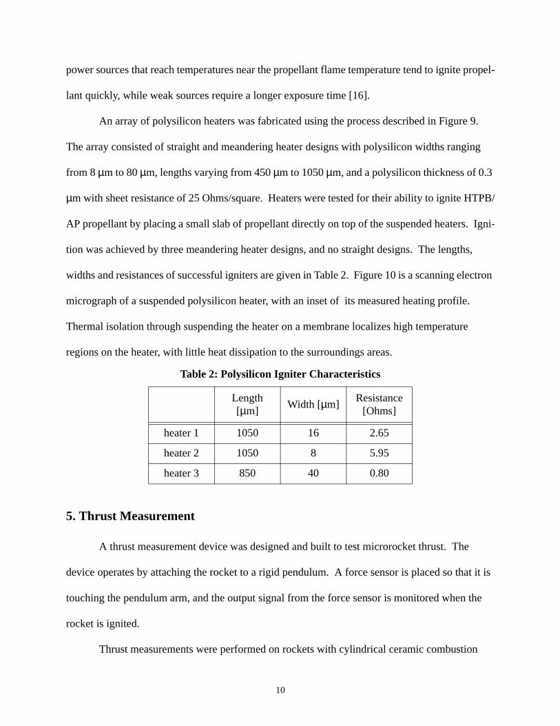
An array of polysilicon heaters was fabricated using the process described in Figure 9.
The array consisted of straight and meandering heater designs with polysilicon widths ranging
from 8 µm to 80 µm, lengths varying from 450 µm to 1050 µm, and a polysilicon thickness of 0.3
µm with sheet resistance of 25 Ohms/square. Heaters were tested for their ability to ignite HTPB/
AP propellant by placing a small slab of propellant directly on top of the suspended heaters. Igni-
tion was achieved by three meandering heater designs, and no straight designs. The lengths,
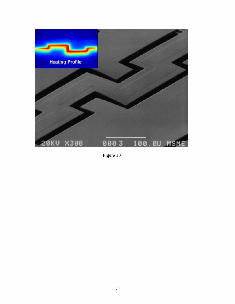
widths and resistances of successful igniters are given in Table 2. Figure 10 is a scanning electron
micrograph of a suspended polysilicon heater, with an inset of its measured heating profile.
Thermal isolation through suspending the heater on a membrane localizes high temperature
regions on the heater, with little heat dissipation to the surroundings areas.
5. Thrust Measurement
A thrust measurement device was designed and built to test microrocket thrust. The
device operates by attaching the rocket to a rigid pendulum. A force sensor is placed so that it is
touching the pendulum arm, and the output signal from the force sensor is monitored when the
rocket is ignited.
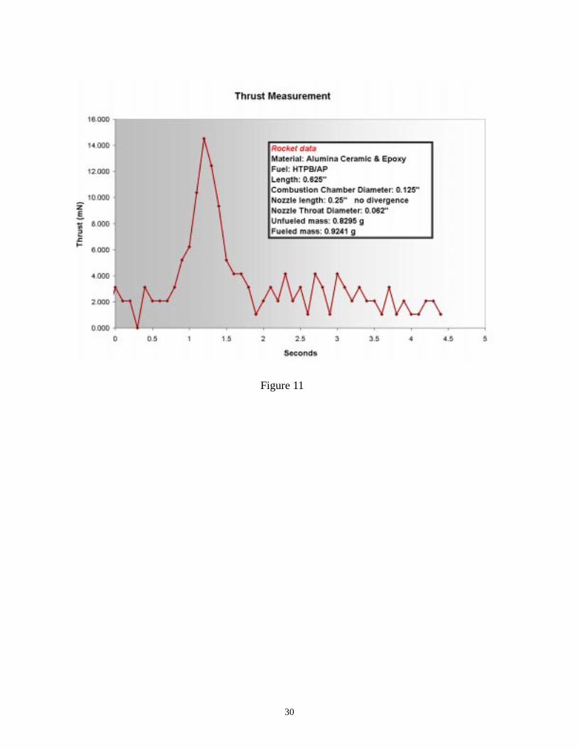
Thrust measurements were performed on rockets with cylindrical ceramic combustion
Table 2: Polysilicon Igniter Characteristics
Length [µm]
Width [µm]Resistance
[Ohms]
heater 1 1050 16 2.65
heater 2 1050 8 5.95
heater 3 850 40 0.80
11
chambers and nozzles. Combustion chambers had diameters of 3.19 cm and lengths of either 1.27
cm in or 2.54 cm. Ceramic nozzles had no divergence, a throat diameter of 0.157 cm, and lengths
of either 0.635 cm or 1.27 cm A commercial hobby rocket wire filament igniter was used by
inserting it into small holes in the combustion chamber near the nozzle. Despite the non-optimal
nozzle and observations that some exhaust exited the igniter holes, thrust with maximum values in
the 10-20 mN range was measured at atmospheric pressure at approximately 300 K. Figure 11
shows a typical thrust curve for a ceramic rocket. During the initial thrust peak, enough thrust is
generated to lift the weight of the 0.92 g rocket in air for approximately 0.3 s. Total burn time for
the rocket corresponding to Figure 11 is estimated at 3 s which yields a burn rate of 3 mms-1.
6. Power Conversion
The total available energy available in the microrocket system is the propellant energy
plus the input ignition energy. Burning 0.1 g of 5 kJg-1 fuel yields 500 J, and the igniter is pow-
ered by 1 W for roughly 1 s, providing an additional 1 J. Only about a small fraction of this
energy is converted into kinetic energy to move the rocket, while much of it is dissipated as heat.
Therefore, a thermal gradient of potentially hundreds of degrees centigrade can exist between the
combustion flame front and the outer edges of the rocket. Thermocouples are often used as ther-
mal sensors because they convert temperature differences into proportional voltages. The ther-
moelectric effects that govern this type of thermal conversion make thermopiles, or multiple
junction thermocouples, useful energy converters capable of converting thermal energy into elec-
trical energy.
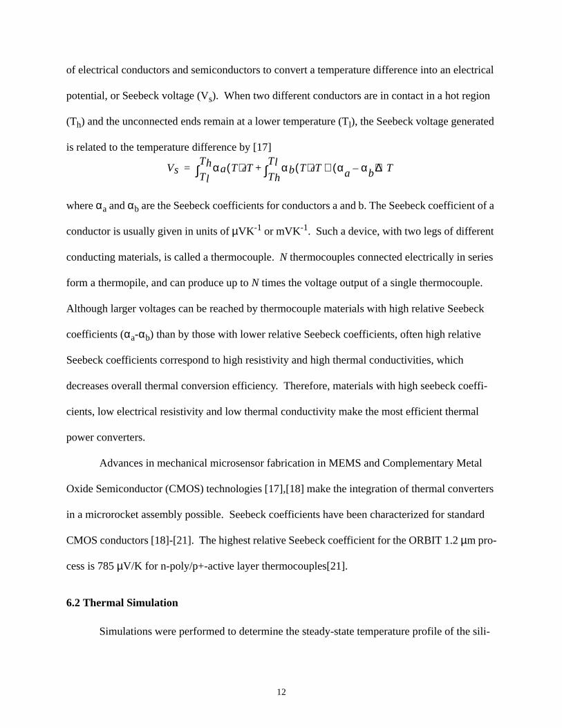
6.1 The Seebeck Effect
The thermoelectric effect discovered by Seebeck in 1826 addresses the material property
12
of electrical conductors and semiconductors to convert a temperature difference into an electrical
potential, or Seebeck voltage (Vs). When two different conductors are in contact in a hot region
(Th) and the unconnected ends remain at a lower temperature (Tl), the Seebeck voltage generated
is related to the temperature difference by [17]
where αa and αb are the Seebeck coefficients for conductors a and b. The Seebeck coefficient of a
conductor is usually given in units of µVK-1 or mVK-1. Such a device, with two legs of different
conducting materials, is called a thermocouple. N thermocouples connected electrically in series
form a thermopile, and can produce up to N times the voltage output of a single thermocouple.
Although larger voltages can be reached by thermocouple materials with high relative Seebeck
coefficients (αa-αb) than by those with lower relative Seebeck coefficients, often high relative
Seebeck coefficients correspond to high resistivity and high thermal conductivities, which
decreases overall thermal conversion efficiency. Therefore, materials with high seebeck coeffi-
cients, low electrical resistivity and low thermal conductivity make the most efficient thermal
power converters.
Advances in mechanical microsensor fabrication in MEMS and Complementary Metal
Oxide Semiconductor (CMOS) technologies [17],[18] make the integration of thermal converters
in a microrocket assembly possible. Seebeck coefficients have been characterized for standard
CMOS conductors [18]-[21]. The highest relative Seebeck coefficient for the ORBIT 1.2 µm pro-
cess is 785 µV/K for n-poly/p+-active layer thermocouples[21].
6.2 Thermal Simulation
Simulations were performed to determine the steady-state temperature profile of the sili-
Vs αa T( ) T αb T( ) T αa αb–( )∆T≅dTh
Tl∫+d
Tl
Th∫=
13
con nozzle die that could be expected during rocket combustion. Silicon nozzle die with varying
sizes and volumes of thermal isolation holes were simulated to determine the effectiveness of the
thermal isolation holes etched beneath the thermopile structures. The plot in Figure 12 shows
simulated temperature distributions for various thermal isolation hole patterns along the silicon
surface, starting from the nozzle and progressing radially outward. This simulation assumes a
constant 1000 K at the nozzle opening and 300 K ambient temperature under convective air flow
conditions. It is clear that increasing the volume of holes around the “thermal isolation ring,” the
donut-shaped area separating hot and cold thermopile junctions, results in larger temperature dif-
ferentials from one side of the ring to the other. The size of the isolation holes does not seem to be
much of a factor, given that the same total hole volume is removed in the additional large and
small hole cases. According to the simulation, the steady-state temperature difference between
the hot side of the thermopile and the cold side of the thermopile is approximately 125 K.
6.3 Testing
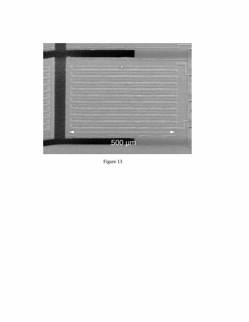
Thermocouple material combinations of n-poly, p-poly and aluminum were fabricated in
the process described in Figure 9. A fabricated n-poly/aluminum thermopile is shown in the
micrograph in Figure 13. Thermopiles made up of ten thermocouple junctions were fabricated
and tested on chips similar to the nozzle die described in section 3.2. The test die did not have a
nozzle hole such that the polysilicon heater was heating the substrate directly. P-poly/metal, n-
poly/metal and n-poly/p-poly thermopiles were tested. Some of the thermopiles fabricated had
their cold end positioned so that it was completely suspended over the cavity, while the rest had
both hot and cold junctions located on the silicon with only the legs suspended over thermal isola-
tion holes. Figure 14a&b show the voltage and power thermopile output plotted versus input
heater power, where 200 mW of heater power corresponds roughly to a 70oC heater temperature
14
rise. Thermopiles achieved steady-state output values within 1 second of heater turn-on, and
required approximately 1.6 seconds to return to a nominal output value.
Correlating the 70oC heater temperature increase linearly with the 700oC simulated tem-
perature differential from nozzle to chip edge, a 12.5oC temperature differential between the hot
and cold side of the thermopile can be assumed. This corresponds to a Seebeck coefficient of 320
µW/K for p-poly/n-poly 10-junction thermopiles (32 µW/K per thermocouple), about 4% of the
maximum reported values. Each nozzle die has twelve sets of ten-junction thermopiles, for a total
of 120 thermocouple junctions. From the 125o C steady-state temperature differential predicted
by the simulation, an estimated 1Volt and 0.5 µW is achievable during steady-state propellant
combustion using currently fabricated thermopiles. Assuming a more optimal Seebeck coeffi-
cient of 785 µV/K for a p-poly/n-poly thermocouple junction and a ten-junction thermopile resis-
tance of 50 kOhms, nearly 12 V and 60 µW could potentially be generated on a nozzle chip for
about 3 s, which is about 4x10⁻⁷ of the total available energy of the rocket system. With HTPB/
AP flame temperatures capable of reaching over 3000oC, the simulated steady-state 125oC tem-
perature differential can be considered quite conservative.
7. Conclusions
Design and fabrication of millimeter-scale rockets have been presented. Microrockets of
mass less than 1 g are capable of producing thrust in the tens of mN for nearly half of a second.
For 10 mN generated over 0.5 seconds, velocities of 5 to 25 m/s can be reached by a 1 g micro-
rocket in space, including a Smart Dust payload. A microfabrication process for a microrocket
nozzle integrated with polysilicon igniters and thermal power converters with backside-etched
thermal isolation cavities has been completed. Ignition of HTPB/AP propellant by polysilicon
resistive heaters has been demonstrated. Thermopiles were fabricated in the same process; n-

15
poly/p-poly thermopiles generated the highest voltage and output power. It is estimated conserva-
tively that over 0.5 µW could be generated at more than 1 volt by a rocket in flight for 2 to 3 sec-
onds, however, thermopiles with higher Seebeck coefficients could produce up to 60 µW.
16
References
[1] 4.0 Strategic Technology Areas, Nasa Technology Plan, http://technologyplan.nasa.gov,
1998
[2] J. M. Kahn, R. H. Katz and K. S. J. Pister, “Mobile Networking for Smart Dust,” ACM/
IEEE Intl. Conf. on Mobile Computing and Networking (MobiCom 99), Seattle, WA,
August 17-19, 1999.
[3] V. Hsu, J. M. Kahn, and K. S. J. Pister, "Wireless Communications for Smart Dust," Elec-
tronics Research Laboratory Technical Memorandum Number M98/2, February, 1998.
[4] Last, M., Pister, K., "2DOF Actuated Micromirror Designed for Large DC Deflection,"
MOEMS 99.
[5] Atwood, B., Warneke, B., Pister, K., “Preliminary Circuits for Smart Dust,” 2000 South-
west Symposium on Mixed-Signal Design, Feb 2000.
[6] Janson, S.W., Helvajian, H., Hansen, W., Lodmell, Lt. J. “Microthrusers for nanosatel-
lites,” Proc. MicroNanotechnology for Space Applications, Vol. 1, April 1999.
[7] Rossi, C., et al, “A new generation of MEMS based Microthrusters for Microspacecraft
Applications,” Proc. MicroNanotechnology for Space Applications, Vol. 1, April 1999.
[8] Musser, G. and Alpert, M., “How to Go to Mars,” Scientific American, vol. 282, No. 3.
March 2000, pp. 44-51.
[9] Koeneman, P. B., Busch-Vishniac, I. J., Wood, K. L., “Feasibility of Micro Power Sup-
plies for MEMS, Journal of Microelectromechanical Systems,” vol. 6, No. 4, Dec 1997.
[10] Purrington, G.W., Plastic Resin Bonded High Energy Rocket Fuel Systems, Firefox Enter-
prises, Inc. 1989.
17
[11] Kishore, K., Gayarthri, V., “Chemistry of Ignition and Combustion of Ammonium-Per-
chlorate-Based Propellants,” Fundamentals of Solid Propellant Combustion, Chpt. 2, ed.
Kuo, K.K., Summerfield, M., Prog in Astronautics and Aeronautics, vol. 90, 1984.
[12] Sigman, R. K., Price, E. W., Chakravarthy, S. R., and Zachary, E. K., “Subignition Heating
Tests for Flake and Powdered Aluminum,” Proc. 3rd Annual JANNAF Combustion Meet-
ing, Monterey, CA, CPIA, November 1996.
[13] Ayon, A., Bayt, R., Lin, C., Braff, R., Sawin, H., Schmidt, M., “Etching Characteristics
and Profile Control in a Time Multiplexed Inductively Coupled Plasma Etcher,” Sensors
and Actuators Workshop, Hilton Head 1998.
[14] Janson, S., Helavijian, H., “Batch-Fabricated Microthrusters: Initial Results,” 32nd SISS/
ASME/SAE/ASEE Joint Propulsion Conference, Lake Buena Vista, FL, 1996.
[15] Bayt, R.L., Breuer, K.,S., Ayon, A.A., “DRIE-Fabricated Nozzles for Generating Super-
sonic Flows in Micropropulsion Systems,” Proc. of the Solid-State Sensor and Actuator
Workshop. Hilton Head, S.C. June 1998.
[16] Williams, F.A., Combustion Theory, 2nd ed., Benjamin/Cummings Pub. Co., Menlo Park,
CA, 1985.
[17] Baltes, H., Moser, D., Freidemann, V., “Thermoelectric Microsensors and Microsystems,
Mechanical Sensors,” Sensors vol. 7 ed. Bau, H.H., de Rooji, B., Kloeck, VCH Verlag,
Weinheim, pp.13-55, 1994.
[18] Jaeggi, D. Thermal Converters by CMOS Technology, Ph.D. Thesis, Zurich: Physical
Electronics Laboratory. 1996.
[19] Leggenhager, R., and Baltes, H., “Improved Thermoelectric Infrared Sensor Using Double
Poly CMOS Technology,”Intl. Conference on Solid-State Sensors and Actuators (Trans-
18
ducers ‘93), pp.1008-1011, June, 1993.
[20] Muller, M. et al, “A Thermoelectric Infrared Radiation Sensor with Monolithically Inte-
grated Amplifier Stage and Temperature Sensor,” Intl. Conference on Solid-State Sensors
and Actuators (Transducers ‘95), pp. 640-643, June, 1995.
[21] Olgun, Z., Akar, O., Kulah, H., and Tayfun, “An Integrated Thermopile Structure with
High Responsivity Using any Standard CMOS Process,” A. Intl. Conference on Solid-
State Sensors and Actuators (Transducers ‘97), pp.1263-1266, June, 1997.
19
List of Figures
Figure 1. Smart Dust Components
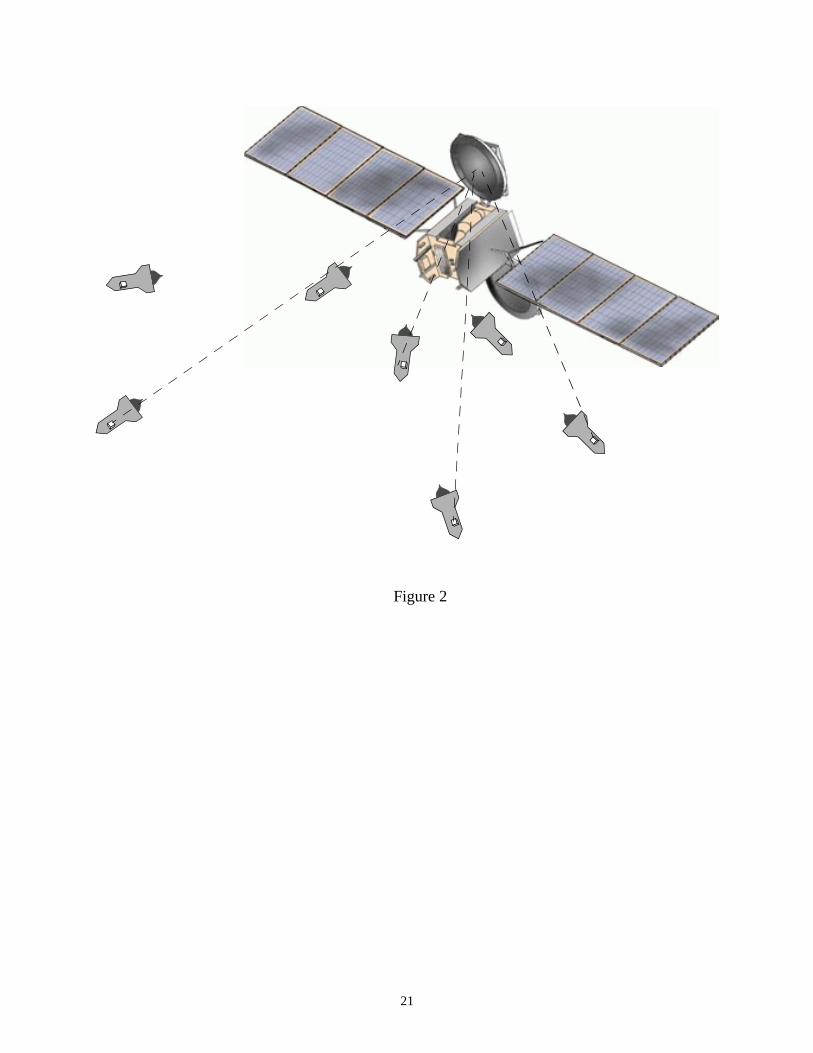
Figure 2. Microrockets with Smart Dust payloads deploying, while maintaining periodic commu-nication with satellite (satellite image courtesy of TheTech museum of innovation)
Figure 3. Schematic diagram of types of chemical rocket propellants
Figure 4. Diagram of heterogeneous (composite) solid propellant Oxidizer particles are suspended in fuel binder. Mixing of gaseous fuel and oxidizer occurs directly above the propel-lant surface and below the flame.
Figure 5. a) HTPB/AP combustion in a 3x4x1.5 mm ceramic combustion chamber. b) HTPB/AP/Al combustion in same chamber. Al particles can be seen combusting outside the rocket.
Figure 6. Silicon wafer with DRIE combustion chambers and nozzles, and detail of chamber design.
Figure 7. Rocket Assembly and nozzle layout view. The igniter spans the nozzle in the center and thermopiles are placed around the outer edge of the chip.
Figure 8. Assembled microrocket. Ceramic combustion chamber epoxied to silicon nozzle die.
Figure 9. Process flow showing thermopile fabrication. Igniters and nozzles are made in the same process.
Figure 10. Polysilicon igniter suspended on an LSN membrane. Inset: measured heating profile at 8V, 2.6mA. Max temp = 182oC
Figure 11. Sample ceramic rocket thrust curve
Figure 12. Plot of temperture vs. distance along silicon surface. Various hole configurations in thermal isolation ring compared.
Figure 13. A ten-junction n-poly/aluminum thermopile suspended on LSN membrane.
Figure 14. Plots of Thermopile a) Voltage and b) Power vs. Heater Power. N-poly/p-poly ther-mopiles generate the highest voltage and power.
20
Figure 1
21
Figure 2
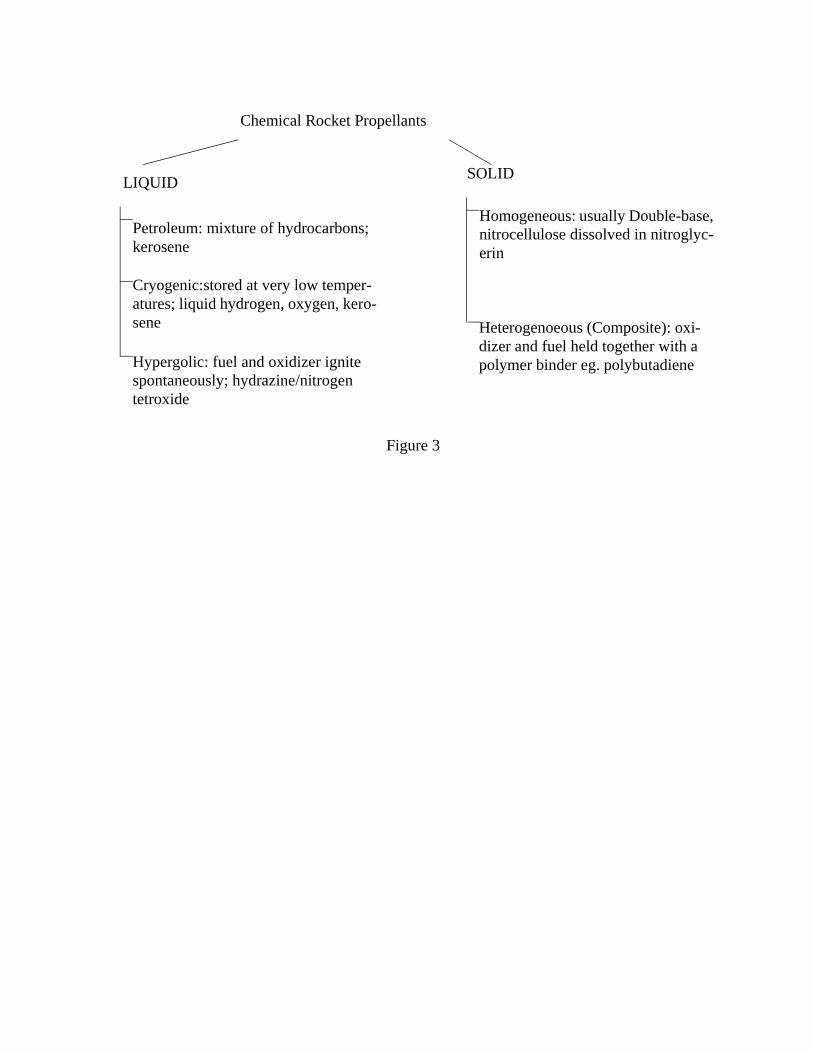
Chemical Rocket Propellants
LIQUID
Petroleum: mixture of hydrocarbons; kerosene
Cryogenic:stored at very low temper-atures; liquid hydrogen, oxygen, kero-sene Heterogenoeous (Composite): oxi-
dizer and fuel held together with a polymer binder eg. polybutadiene
SOLID
Homogeneous: usually Double-base, nitrocellulose dissolved in nitroglyc-erin
Hypergolic: fuel and oxidizer ignite spontaneously; hydrazine/nitrogen tetroxide
Figure 3
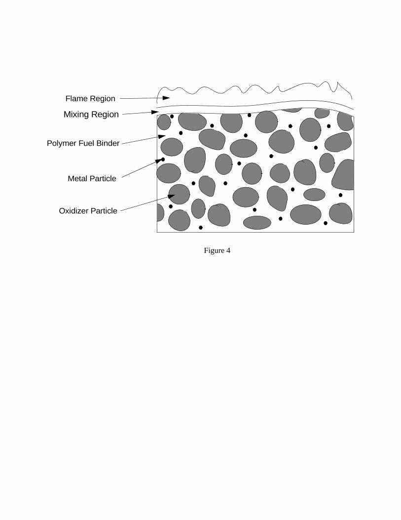
Oxidizer Particle
Metal Particle
Polymer Fuel Binder
Figure 4
Mixing Region
Flame Region
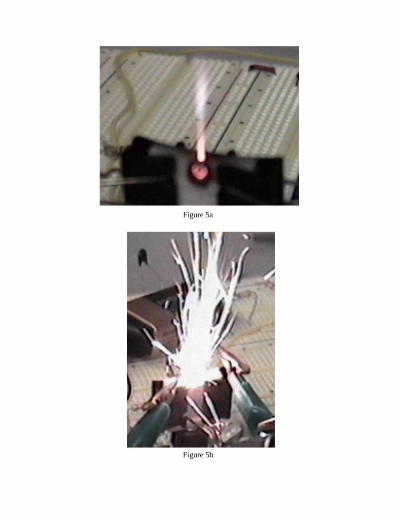
Figure 5a
Figure 5b
3 mm
4 mm
0.5 - 1.5 mm
propellant
combustionchamber
Figure 6
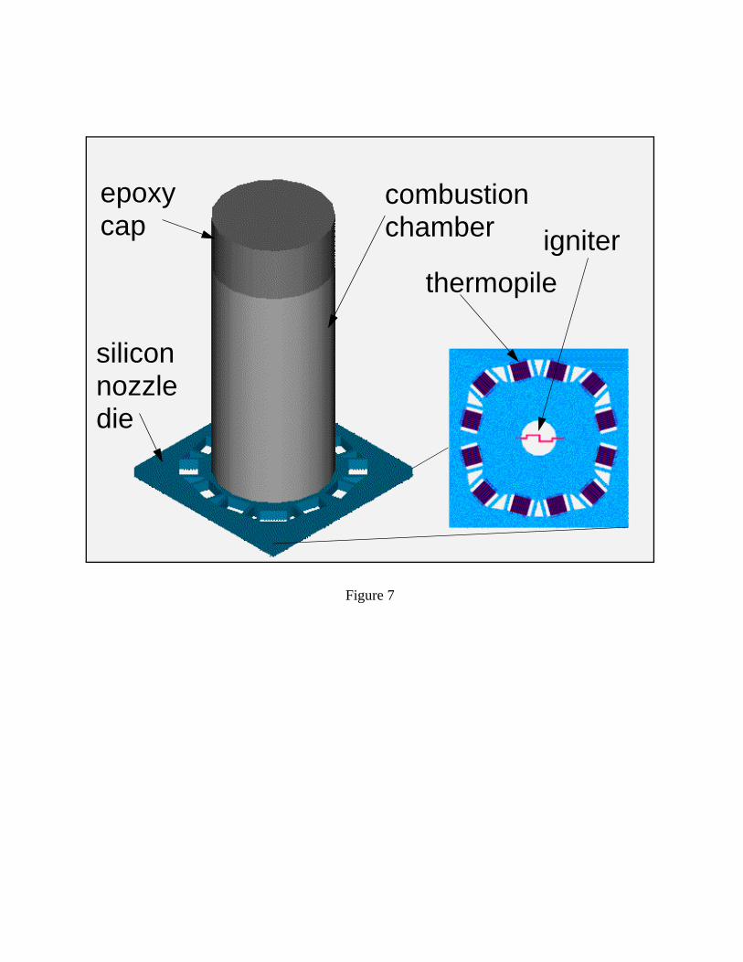
Figure 7
thermopile
igniter
combustionchamber
silicon nozzledie
epoxy cap
8.5 mm
Figure 8
Epoxy Cap
Ceramic CombustionChamber
Silicon Nozzle Die
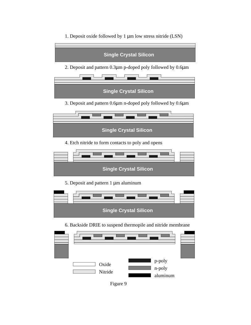
6. Backside DRIE to suspend thermopile and nitride membrane
Single Crystal Silicon
Single Crystal Silicon
Single Crystal Silicon
Single Crystal Silicon
1. Deposit oxide followed by 1 µm low stress nitride (LSN)
2. Deposit and pattern 0.3µm p-doped poly followed by 0.6µm
3. Deposit and pattern 0.6µm n-doped poly followed by 0.6µm
5. Deposit and pattern 1 µm aluminum
Single Crystal Silicon
4. Etch nitride to form contacts to poly and opens
Oxide
Nitride
p-poly
n-poly
aluminum
Figure 9
29
Figure 10
30
Figure 11
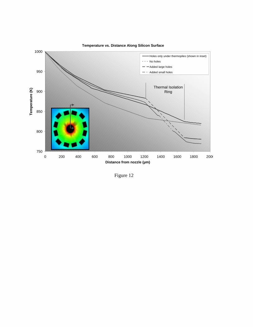
Figure 12
Temperature vs. Distance Along Silicon Surface
750
800
850
900
950
1000
0 200 400 600 800 1000 1200 1400 1600 1800 2000
Distance from nozzle (µm)
Tem
per
atu
re (
K)
Holes only under thermopiles (shown in inset)
No holes
Added large holes
Added small holes
Thermal Isolation Ring
500 µm
Figure 13
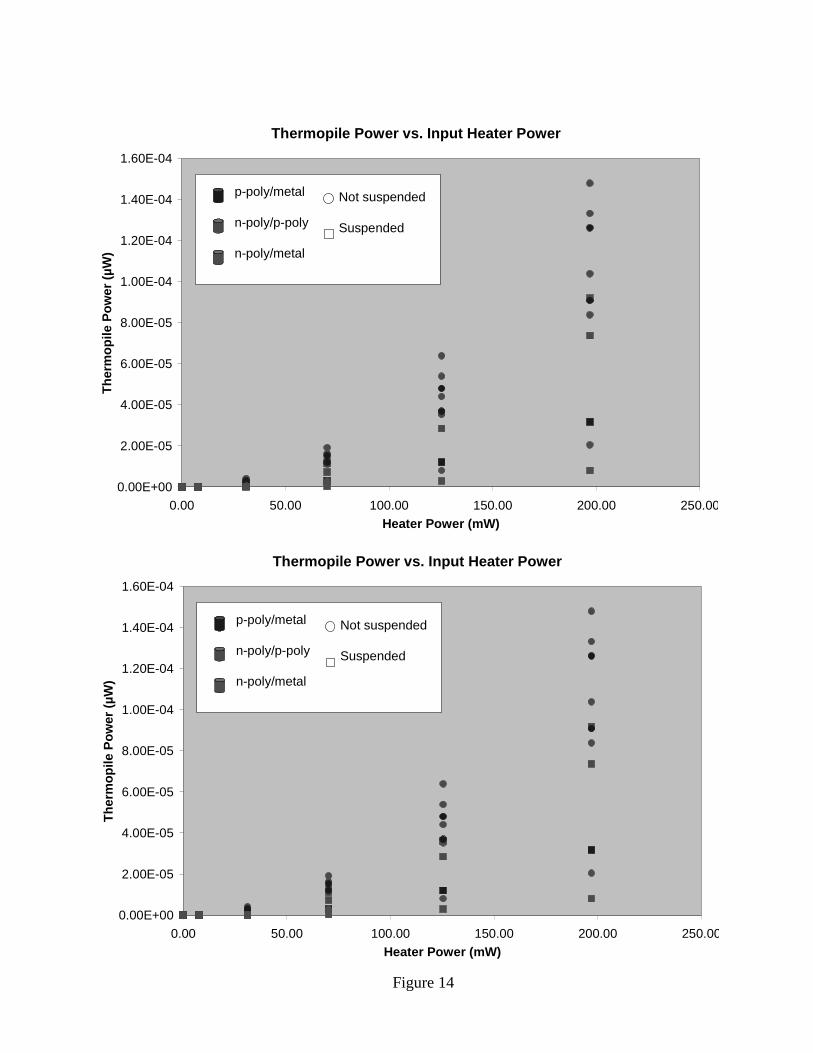
Figure 14
Thermopile Power vs. Input Heater Power
0.00E+00
2.00E-05
4.00E-05
6.00E-05
8.00E-05
1.00E-04
1.20E-04
1.40E-04
1.60E-04
0.00 50.00 100.00 150.00 200.00 250.00Heater Power (mW)
The
rmop
ile P
ower
(µW
)
Not suspended
Suspended
p-poly/metal
n-poly/p-poly
n-poly/metal
Thermopile Power vs. Input Heater Power
0.00E+00
2.00E-05
4.00E-05
6.00E-05
8.00E-05
1.00E-04
1.20E-04
1.40E-04
1.60E-04
0.00 50.00 100.00 150.00 200.00 250.00Heater Power (mW)
The
rmop
ile P
ower
(µW
)
Not suspended
Suspended
p-poly/metal
n-poly/p-poly
n-poly/metal