microseismic industry consortium annual research …
TRANSCRIPT
MICROSEISMIC INDUSTRY CONSORTIUM
Annual Research Report: Volume 6 - 2016
University of Alberta
Department of PhysicsEdmonton, Alberta
Canada
and
University of Calgary
Department of GeoscienceCalgary, Alberta
Canada
February, 2016


Contents
1 Enrico Caffagni, Gotz Bokelmann, Christopher I. McDermott, David W. Eaton and Mirko van der Baan: Beyond
microseismicity: an overview of geophysical monitoring in hydrocarbon reservoirs 1
1.1 Introduction . . . . . . . . . . . . . . . . . . . . . . . . . . . . . . . . . . . . . . . . . . . . . . . . . . . . . . 1
1.2 Monitoring a hydrocarbon reservoir . . . . . . . . . . . . . . . . . . . . . . . . . . . . . . . . . . . . . . . . . . 2
1.3 Properties and Monitored Quantities . . . . . . . . . . . . . . . . . . . . . . . . . . . . . . . . . . . . . . . . . 3
1.4 Overview of the Geophysical Monitoring Techniques . . . . . . . . . . . . . . . . . . . . . . . . . . . . . . . . . 4
1.5 Discussion . . . . . . . . . . . . . . . . . . . . . . . . . . . . . . . . . . . . . . . . . . . . . . . . . . . . . . . 10
1.6 Conclusions . . . . . . . . . . . . . . . . . . . . . . . . . . . . . . . . . . . . . . . . . . . . . . . . . . . . . . 10
1.7 Acknowledgments . . . . . . . . . . . . . . . . . . . . . . . . . . . . . . . . . . . . . . . . . . . . . . . . . . . 10
1.8 References . . . . . . . . . . . . . . . . . . . . . . . . . . . . . . . . . . . . . . . . . . . . . . . . . . . . . . . 10
i

ii
Chapter 1
Beyond microseismicity: an overview ofgeophysical monitoring in hydrocarbonreservoirs
Enrico Caffagnia, Gotz Bokelmanna, Christopher I. McDermottb,David W. Eatonc and Mirko van der Baand
aDept. of Meteorology and Geophysics, Univ. of Vienna, Vienna, 1090, AustriaE: [email protected], [email protected] of Geosciences Edinburgh University, Edinburgh, EH1, UK.
E: [email protected]. of Geoscience, Univ. of Calgary, Calgary, AB, T2N 1N4, Canada.
E: [email protected]. of Physics, Univ. of Alberta, Edmonton, AB, T6G 2E1, Canada.
Summary
Extraction of hydrocarbons from unconventional reservoirs de-mands ever-increasing technological effort, and there is need forbetter understanding phenomena occurring within the reservoir.The focus of the petroleum industry has shifted from explorationto monitoring production, and it is essential to monitor the pro-cesses in the subsurface (4). Significant deformation processeshappen when man-made stimulation is performed, in combina-tion with effects deriving from the existing natural conditionssuch as stress regime in situ or pre-existing fracturing. Temporalchanges from an initial (unaltered) state of the reservoir can beassociated to alterations in the rock properties, temperature andpressure or fluid flow.Keeping track of such changes in reservoir is important, on onehand for improving recovery of hydrocarbons, and on the otherhand to assure safe and proper mode operation. Monitoring be-comes particularly important when hydraulic fracturing (HF) isused, especially in the form of the much-discussed “fracking”.
Monitoring hydrocarbon reservoirs has essentially two purposes.First it allows geoscientists and engineers to understand how thereservoir reacts to external or internal perturbation of its state;secondly, monitoring is one of the first steps in preventing andaddressing environmental issues (e.g., gas leakage in a close byaquifer). Monitoring contributes to reducing the uncertainty inthe reservoir’s dynamics. A combination of monitoring proce-dures and good operational practice is necessary for exploitingnatural reserves in reservoirs, while minimizing the environmen-tal impact.
1.1 IntroductionHydraulic-Fracturing (HF) is a sophisticated technique whichis widely applied in low-permeability geological formations toenhance the production of natural hydrocarbons. In principle,similar HF techniques have been applied in Europe for a longtime in conventional reservoirs, and are likely to be intensifiedin the near future. When HF is used, especially in the form of
1
Caffagni, Bokelmann, McDermott,Eaton and Vander Baan Microseismic Industry Consortium Vol. 6 – Chapter 1
the much-discussed “fracking”, knowledge of the state of thereservoir becomes important, both for optimizing operations,and also to safeguard against potential hazards. This suggests anincreasing demand in technological development, including up-dating and adapting existing techniques in applied geophysics.
The first attempts of tracking temporal changes (monitoring) inhydrocarbon reservoir are dated 40-50 years ago. These surveyswere mainly focused on characterizing the subsurface usingprobes, such as seismic and electric, deployed in boreholes or atthe surface. Reservoirs are nowadays monitored during explo-ration and exploitation of the hydrocarbons by using differentmonitoring techniques, according to the geological conditions.Techniques have been developed and are still in usage in off-shore plays, with different design from the on-shore case. Someof these techniques aim at constructing images of the reser-voir compartments; others can estimate important parametersdirectly in-situ. Nevertheless, the output of geophysical surveysneeds robust interpretation and may not exhaustively explain thecause of changes in reservoir.
In this work we review currently available geophysical tech-niques for reservoir monitoring.First, we describe basic characteristics of geophysical monitor-ing, and we identify properties and the associated monitoredquantities in a hydrocarbon reservoir, according to the differentfields of analysis in reservoir.Second, we present an overview of current monitoring tech-niques associating them to monitored quantities.
This work has been carried out as part of the FracRisk con-sortium (www.fracrisk.eu); this project is funded by the Hori-zon2020 European Union (EU) research programme, and it aimsat developing a knowledge base for helping minimize the envi-ronmental footprint of shale-gas exploration and exploitation.
1.2 Monitoring a hydrocarbonreservoir
Hydrocarbon reservoirs are composed substantially by rockscontaining different minerals, fluids (water) and hydrocarbons(oil or natural gas). Natural reserves can be trapped in geologicalformations at variable depth depending on the geological condi-tions in reservoir. Each reservoir is characterized by its naturalconditions, such as faulting and folding that contributed to theformation of an existing network of natural fractures. Uncon-ventional reservoirs are characterized by very low-permeabilitygeological formations bearing hydrocarbons, as opposed to con-ventional reservoirs, where rock permeability is higher by manyorders of magnitude. Hydrocarbons are usually extracted fromunconventional reservoirs by artificial stimulation, which gener-ates significant changes in the reservoir.
Geophysical monitoring implies keeping track of temporalchanges of characteristics (later called “properties”) of a reser-voir that are imposed by external or internal perturbation ofthe reservoir state; such changes may not only allow inferencesto be made on the reaction of the reservoir to the perturba-tion (e.g., in terms of deformation, fluid flow or temperaturechanges), but also give information on reservoir properties thatwere previously hidden (e.g., 4). Monitoring can be achievedby implementing probes in-situ (directly into the reservoir), oroutside of the reservoir, where the non-invasive nature of themethod prevents any further perturbation of the reservoir
Let us assume that a hydrocarbon reservoir is analyzed in-situ attime t0. If no external stimulation is applied, the reservoir is un-altered, and remains in its initial state. Natural variations can bedue to the background stress in the underground rocks, forces oftectonic, volcanic, or tidal origin, presence of faulting/folding,fracturing, or presence of fluids, such as water and hydrocar-bons. At time t1 an artificial stimulation starts to be applied andit is terminated at time t2. The time interval between t1 and t2refers to the stimulation; much of its effects should occur withinthis time interval, on top of any occurring natural variations.After t2 the stimulation is stopped, however significant effectsmay still occur. After the stimulation, the reservoir will unlikelyreturn to its exact initial condition at t0. After a certain time,changes may not be detected anymore; however the reservoircharacteristics will usually differ from those at t1.Monitoring refers to tracking the temporal changes of the reser-voir, starting from its initial state at time t0, to a possibly longtime after t2. A baseline study of the hydrocarbon reservoirshould be conducted before the stimulation (e.g., fracking) toobtain the background state, which provides an objective pointof comparison for the reservoir state as measured during andafter the stimulation. In this way, both the natural and artificialdeformation processes can be tracked; where possible, these twocontributions should be distinguished.
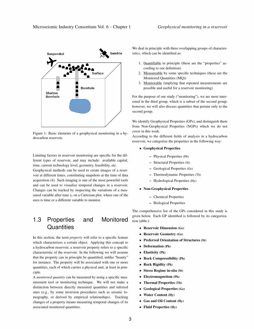
Geophysical monitoring requires a detection geometry, whichcan be adapted to the type of reservoir. A number of detectiongeometries are shown in Figure 1 and listed hereafter:
• Surface
• Borehole
• Shallow borehole
• Satellite
• Suspended in air/water
The specific design may include sensors suspended in air orwater, such as in the monitoring of off-shore reservoirs, whereinstrumentation can be deployed in the water and/or towed by aship, or in airborne surveys.
2
Microseismic Industry Consortium Vol. 6 – Chapter 1 Geophysical monitoring in a reservoir
Figure 1: Basic elements of a geophysical monitoring in a hy-drocarbon reservoir.
Limiting factors in reservoir monitoring are specific for the dif-ferent types of reservoir, and may include: available capital,time, current technology level, geometry, feasibility, etc.Geophysical methods can be used to create images of a reser-voir at different times, constituting snapshots at the time of dataacquisition (4). Such imaging is one of the most powerful toolsand can be used to visualize temporal changes in a reservoir.Changes can be tracked by inspecting the variations of a mea-sured variable after time t0 on a Cartesian plot, where one of theaxes is time or a different variable to monitor.
1.3 Properties and MonitoredQuantities
In this section, the term property will refer to a specific featurewhich characterizes a certain object. Applying this concept toa hydrocarbon reservoir, a reservoir property refers to a specificcharacteristic of the reservoir. In the following we will assumethat the property can in principle be quantified, unlike “beauty”for instance. The property will be associated with one or morequantities, each of which carries a physical unit, at least in prin-ciple.A monitored quantity can be measured by using a specific mea-surement tool or monitoring technique. We will not make adistinction between directly measured quantities and inferredones (e.g., by some inversion procedures such as seismic to-mography, or derived by empirical relationships). Trackingchanges of a property means measuring temporal changes of itsassociated monitored quantities.
We deal in principle with three overlapping groups of character-istics, which can be identified as:
1. 0uantifiable in principle (these are the “properties” ac-cording to our definition)
2. Measureable by some specific techniques (these are theMonitored Quantities (MQ))
3. Monitorable (implying that repeated measurements arepossible and useful for a reservoir monitoring)
For the purpose of our study (“monitoring”), we are most inter-ested in the third group, which is a subset of the second group;however, we will also discuss quantities that pertain only to thesecond group.
We identify Geophysical Properties (GPs), and distinguish themfrom Non-Geophysical Properties (NGPs) which we do notcover in this work.According to the different fields of analysis in a hydrocarbonreservoir, we categorize the properties in the following way:
• Geophysical Properties
– Physical Properties (Ph)
– Structural Properties (St)
– Geological Properties (Ge)
– Thermodynamic Properties (Th)
– Hydrological Properties (Hy)
• Non-Geophysical Properties
– Chemical Properties
– Biological Properties
The comprehensive list of the GPs considered in this study isgiven below. Each GP identified is followed by its categoriza-tion (abbr.):
• Reservoir Dimension (Ge)
• Reservoir Geometry (Ge)
• Preferred Orientation of Structures (St)
• Deformation (Ph)
• Elasticity (Ph)
• Rock Compressibility (Ph)
• Rock Rigidity (Ph)
• Stress Regime in-situ (St)
• Electromagnetism (Ph)
• Thermal Properties (Th)
• Geological Properties (Ge)
• Water Content (Hy)
• Gas and Oil Content (Hy)
• Fluid Properties (Hy)
3
Caffagni, Bokelmann, McDermott,Eaton and Vander Baan Microseismic Industry Consortium Vol. 6 – Chapter 1
• Fluid Flow (Hy)
• Faulting/Folding (St)
• Rock Cohesion (St)
• Fracturing (St)
• Radioactivity (Ph)
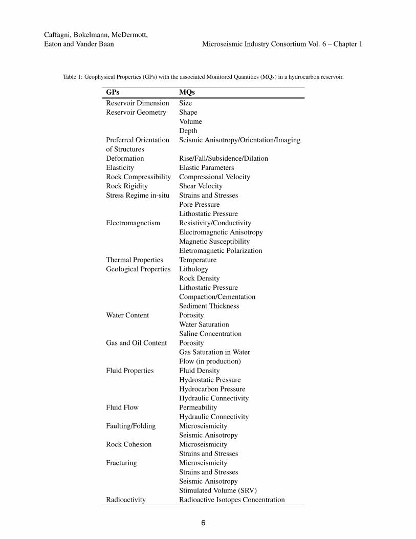
According to the different fields of reservoir analysis, we asso-ciate to each GP one or more specific MQs. In some cases thesame MQ can be associated to different GP, for instance MQstrains and stresses can be associated to GP stress regime in-situand rock cohesion or fracturing. The meaning of some MQswill be explained in the next section, relating to the monitoringtechniques.The complete list of MQs associated to their relative GPs isshown in Table 1.
1.4 Overview of the GeophysicalMonitoring Techniques
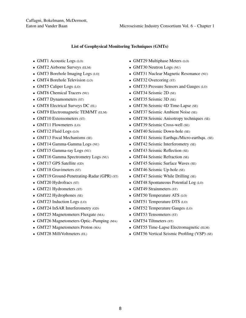
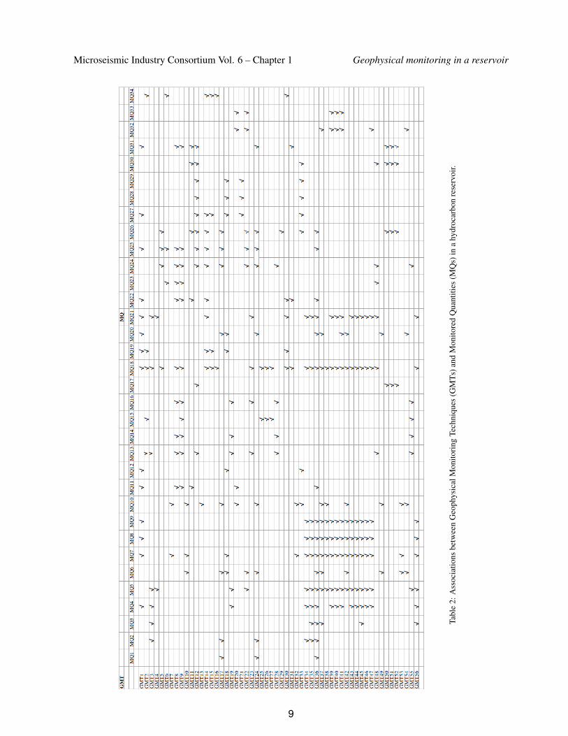
We have previously introduced the Geophysical Properties(GPs) and Monitored Quantities (MQs) in a hydrocarbon reser-voir, showing examples of their associations. A monitoring tech-nique can be applied in a reservoir to monitor several quantities,hence we distinguish “multi-tasking” from “single-tasking”techniques. The former monitor several quantities, while thelatter only monitor a single technique at a time.Each Geophysical Monitoring Technique (GMT) will be pre-sented relating it to its associated MQs. Table 2 shows a compre-hensive lookup on the GMTs, listed in alphabetical order, flag-ging the associated MQs with a ‘V’. This table allows us to iden-tify which GMT is multi- or single-tasking technique.According to the methodologies currently used in monitoring,the GMTs can be divided mainly into eight classes (the wordtechniques in each item is omitted):
• Magnetic (MA)
• Electrical (EL)
• Electromagnetic (ELM)
• Borehole Logging (LO)
• Nuclear (NU)
• Static (ST)
• Seismic (SE)
• Geodetic (GD)
For sake of clarity, this classification is not a rigid order neitheran attempt to rank the GMTs. The abbreviations indicated aftereach technique have the main purpose to help in cataloging andclassifying the GMTs.In our analysis we include the oldest GMTs, namely those in us-age 40-50 years ago in applied geophysics, such as gravimeters,
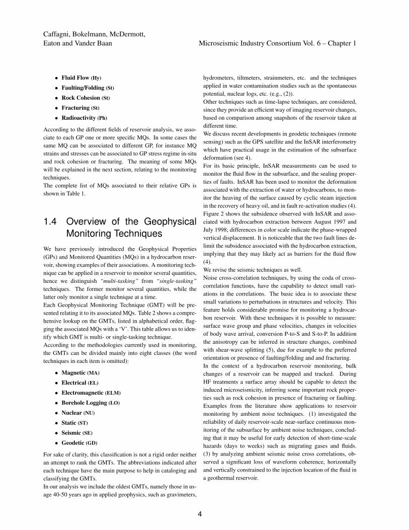
hydrometers, tiltmeters, strainmeters, etc. and the techniquesapplied in water contamination studies such as the spontaneouspotential, nuclear logs, etc. (e.g., (2)).Other techniques such as time-lapse techniques, are considered,since they provide an efficient way of imaging reservoir changes,based on comparison among snapshots of the reservoir taken atdifferent time.We discuss recent developments in geodetic techniques (remotesensing) such as the GPS satellite and the InSAR interferometrywhich have practical usage in the estimation of the subsurfacedeformation (see 4).For its basic principle, InSAR measurements can be used tomonitor the fluid flow in the subsurface, and the sealing proper-ties of faults. InSAR has been used to monitor the deformationassociated with the extraction of water or hydrocarbons, to mon-itor the heaving of the surface caused by cyclic steam injectionin the recovery of heavy oil, and in fault re-activation studies (4).Figure 2 shows the subsidence observed with InSAR and asso-ciated with hydrocarbon extraction between August 1997 andJuly 1998; differences in color scale indicate the phase-wrappedvertical displacement. It is noticeable that the two fault lines de-limit the subsidence associated with the hydrocarbon extraction,implying that they may likely act as barriers for the fluid flow(4).We revise the seismic techniques as well.Noise cross-correlation techniques, by using the coda of cross-correlation functions, have the capability to detect small vari-ations in the correlations. The basic idea is to associate thesesmall variations to perturbations in structures and velocity. Thisfeature holds considerable promise for monitoring a hydrocar-bon reservoir. With these techniques it is possible to measure:surface wave group and phase velocities, changes in velocitiesof body wave arrival, conversion P-to-S and S-to-P. In additionthe anisotropy can be inferred in structure changes, combinedwith shear-wave splitting (5), due for example to the preferredorientation or presence of faulting/folding and and fracturing.In the context of a hydrocarbon reservoir monitoring, bulkchanges of a reservoir can be mapped and tracked. DuringHF treatments a surface array should be capable to detect theinduced microseismicity, inferring some important rock proper-ties such as rock cohesion in presence of fracturing or faulting.Examples from the literature show applications to reservoirmonitoring by ambient noise techniques. (1) investigated thereliability of daily reservoir-scale near-surface continuous mon-itoring of the subsurface by ambient noise techniques, conclud-ing that it may be useful for early detection of short-time-scalehazards (days to weeks) such as migrating gases and fluids.(3) by analyzing ambient seismic noise cross correlations, ob-served a significant loss of waveform coherence, horizontallyand vertically constrained to the injection location of the fluid ina geothermal reservoir.
4
Microseismic Industry Consortium Vol. 6 – Chapter 1 Geophysical monitoring in a reservoir
Figure 2: InSAR-observed subsidence north of Bakersfield, California, associated with hydrocarbon extraction between August1997 and July 1998 (from 4).
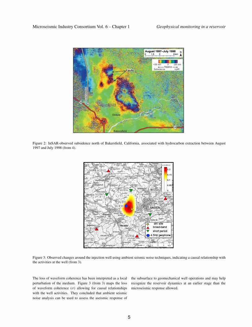
Figure 3: Observed changes around the injection well using ambient seismic noise techniques, indicating a causal relationship withthe activities at the well (from 3).
The loss of waveform coherence has been interpreted as a localperturbation of the medium. Figure 3 (from 3) maps the lossof waveform coherence (σ) allowing for causal relationshipswith the well activities. They concluded that ambient seismicnoise analysis can be used to assess the aseismic response of
the subsurface to geomechanical well operations and may helprecognize the reservoir dynamics at an earlier stage than themicroseismic response allowed.
5
Caffagni, Bokelmann, McDermott,Eaton and Vander Baan Microseismic Industry Consortium Vol. 6 – Chapter 1
Table 1: Geophysical Properties (GPs) with the associated Monitored Quantities (MQs) in a hydrocarbon reservoir.
GPs MQsReservoir Dimension SizeReservoir Geometry Shape
VolumeDepth
Preferred Orientation Seismic Anisotropy/Orientation/Imagingof StructuresDeformation Rise/Fall/Subsidence/DilationElasticity Elastic ParametersRock Compressibility Compressional VelocityRock Rigidity Shear VelocityStress Regime in-situ Strains and Stresses
Pore PressureLithostatic Pressure
Electromagnetism Resistivity/ConductivityElectromagnetic AnisotropyMagnetic SusceptibilityEletromagnetic Polarization
Thermal Properties TemperatureGeological Properties Lithology
Rock DensityLithostatic PressureCompaction/CementationSediment Thickness
Water Content PorosityWater SaturationSaline Concentration
Gas and Oil Content PorosityGas Saturation in WaterFlow (in production)
Fluid Properties Fluid DensityHydrostatic PressureHydrocarbon PressureHydraulic Connectivity
Fluid Flow PermeabilityHydraulic Connectivity
Faulting/Folding MicroseismicitySeismic Anisotropy
Rock Cohesion MicroseismicityStrains and Stresses
Fracturing MicroseismicityStrains and StressesSeismic AnisotropyStimulated Volume (SRV)
Radioactivity Radioactive Isotopes Concentration
6

Microseismic Industry Consortium Vol. 6 – Chapter 1 Geophysical monitoring in a reservoir
List of Monitored Quantities (MQs)
• MQ1 Size• MQ2 Shape• MQ3 Volume• MQ4 Depth• MQ5 Seismic Anisot./Orientation/Imaging• MQ6 Rise/Fall/Subsidence/Dilation• MQ7 Elastic Parameters• MQ8 Compressional Velocity• MQ9 Shear Velocity• MQ10 Strains and Stresses• MQ11 Pore Pressure• MQ12 Lithostatic Pressure• MQ13 Resistivity/Conductivity• MQ14 Electromagnetic Anisotropy• MQ15 Magnetic Susceptibility• MQ16 Electromagnetic Polarization• MQ17 Temperature• MQ18 Lithology• MQ19 Rock Density• MQ20 Compaction/Cementation• MQ21 Sediment Thickness• MQ22 Porosity• MQ23 Water Saturation• MQ24 Saline Concentration• MQ25 Gas Saturation in Water• MQ26 Flow (in production)• MQ27 Fluid Density• MQ28 Hydrostatic Pressure• MQ29 Hydrocarbon Pressure• MQ30 Hydraulic Connectivity• MQ31 Permeability• MQ32 Microseismicity• MQ33 Stimulated Volume (SRV)• MQ34 Radioactive Isotopes Concentration
7
Caffagni, Bokelmann, McDermott,Eaton and Vander Baan Microseismic Industry Consortium Vol. 6 – Chapter 1
List of Geophysical Monitoring Techniques (GMTs)
• GMT1 Acoustic Logs (LO)
• GMT2 Airborne Surveys (ELM)
• GMT3 Borehole Imaging Logs (LO]
• GMT4 Borehole Television (LO)
• GMT5 Caliper Logs (LO)
• GMT6 Chemical Tracers (NU)
• GMT7 Dynamometers (ST)
• GMT8 Electrical Surveys DC (EL)
• GMT9 Electromagnetic TEM/MT (ELM)
• GMT10 Extensometers (ST)
• GMT11 Flowmeters (LO)
• GMT12 Fluid Logs (LO)
• GMT13 Focal Mechanisms (SE)
• GMT14 Gamma-Gamma Logs (NU)
• GMT15 Gamma-ray Logs (NU)
• GMT16 Gamma Spectrometry Logs (NU)
• GMT17 GPS Satellite (GD)
• GMT18 Gravimeters (ST)
• GMT19 Ground-Penetrating-Radar (GPR) (ST)
• GMT20 Hydrofracs (ST)
• GMT21 Hydrometers (ST)
• GMT22 Hydrophones (SE)
• GMT23 Induction Logs (LO)
• GMT24 InSAR Interferometry (GD)
• GMT25 Magnetometers Fluxgate (MA)
• GMT26 Magnetometers Optic.-Pumping (MA)
• GMT27 Magnetometers Proton (MA)
• GMT28 MilliVoltmeters (EL)
• GMT29 Multiphase Meters (LO)
• GMT30 Neutron Logs (NU)
• GMT31 Nuclear Magnetic Resonance (NU)
• GMT32 Overcoring (ST)
• GMT33 Pressure Sensors and Gauges (LO)
• GMT34 Seismic 2D (SE)
• GMT35 Seismic 3D (SE)
• GMT36 Seismic 4D Time-Lapse (SE)
• GMT37 Seismic Ambient Noise (SE)
• GMT38 Seismic Anisotropy techniques (SE)
• GMT39 Seismic Cross-well (SE)
• GMT40 Seismic Down-hole (SE)
• GMT41 Seismic Earthqu./Micro-earthqu. (SE)
• GMT42 Seismic Interferometry (SE)
• GMT43 Seismic Reflection (SE)
• GMT44 Seismic Refraction (SE)
• GMT45 Seismic Surface Waves (SE)
• GMT46 Seismic Up-hole (SE)
• GMT47 Seismic While Drilling (SE)
• GMT48 Spontaneous Potential Log (LO)
• GMT49 Strainmeters (ST)
• GMT50 Temperature ATS (LO)
• GMT51 Temperature DTS (LO)
• GMT52 Temperature Gauges (LO)
• GMT53 Tensometers (ST)
• GMT54 Tiltmeters (ST)
• GMT55 Time-Lapse Electromagnetic (ELM)
• GMT56 Vertical Seismic Profiling (VSP) (SE)
8
Microseismic Industry Consortium Vol. 6 – Chapter 1 Geophysical monitoring in a reservoir
Tabl
e2:
Ass
ocia
tions
betw
een
Geo
phys
ical
Mon
itori
ngTe
chni
ques
(GM
Ts)
and
Mon
itore
dQ
uant
ities
(MQ
s)in
ahy
droc
arbo
nre
serv
oir.
9

Caffagni, Bokelmann, McDermott,Eaton and Vander Baan Microseismic Industry Consortium Vol. 6 – Chapter 1
1.5 DiscussionWe will not describe each technique in detail; we prefer refer-ring the reader to a report on the existing geophysical monitoringtechniques which will be released soon as part of the FracRiskproject.The work presented on existing geophysical monitoring tech-niques does not pretend to be a complete and exhaustive manualsince there is extensive literature in the matter. Rather, one ofthe take-home message is a suggestion to go beyond the mi-croseismicity techniques or hydrofracs, since we deem that it isappropriate to extend the context of monitoring in a hydrocarbonreservoir.
This work on existing monitoring techniques in hydrocarbonreservoirs is primarily intended for the discussion within theFracRisk community. It provides a general description of thecurrently applied techniques that are well-established. In a widefield such as reservoir monitoring, it is clear that the exposure ofindividual techniques can only be rather short in such a text.Beyond FracRisk, this work may also be used as consultationmaterial by both industry and academy in reservoir geophysicalmonitoring or characterization.The work may also be of interest for regulator agencies, to seewhat is possible in principle currently in monitoring reservoirsduring HF, for eventually defining a good operation practice ofgeophysical monitoring in shale-gas reservoirs, in order to min-imize its footprint on the environment.
1.6 ConclusionsA continuous massive usage of hydraulic stimulation in un-conventional reservoirs requires an increasing demand of tech-nology development in monitoring systems. This suggests theimportance of adapting and updating the existing monitoringtechniques. Hydrocarbon reservoirs appear in their initial state(unaltered) mainly under the regime of natural variations. How-ever significant deformations happen after hydraulic-fracturingtreatments in reservoir; these can be associated to changes in therock properties, temperature or fluid flow. Keeping track of suchchanges is useful on one hand for an enhanced hydrocarbon
recovery, and on the other hand to verify the safe and propermode of operation. We describe the basic elements of geophys-ical monitoring, identifying properties and monitored quantitiesin a hydrocarbon reservoir. The current available monitoringtechniques are then reviewed according to the different field ofanalysis in reservoir.
This work has been carried out as part of the FracRisk project(Horizon2020 European Union), which encourages proficientcollaboration between the Academy and Industry for minimiz-ing the environmental footprint of shale-gas exploration and ex-ploitation, which also involves the regulatory bodies and theconcerns of the public opinion.
1.7 AcknowledgmentsThe authors sincerely thank the FracRisk community for con-structive comments and suggestions. This project has receivedfunding from the European Union’s Horizon 2020 research andinnovation programme under grant agreement No 640979.
1.8 References[1] de Ridder, S., and Biondi, B., 2013, Daily reservoir-scale
subsurface monitoring using ambient seismic noise: Geo-physical Research Letters, 40, no. 12, 2969-2974.
[2] Keys, W.S., 1997, A practical guide to borehole geophysicsin environmental investigations: Lewis Publisher.
[3] Obermann, A., Kraft, T., Larose, E., and Wiemer, S., 2015,Potential of ambient seismic noise techniques to monitor theSt. Gallen geothermal site (Switzerland): Journal of Geo-physical Research: Solid Earth, 120, no. 6, 4301-4316.
[4] Snieder, R., Hubbard, S., Haney, M., Bawden, G., Hatchell,P., Revil, A., and Group, D.G.M.W., 2007, Advanced non-invasive geophysical monitoring techniques: Annual Reviewof Earth and Planetary Sciences, 35, no. 1, 653-683.
[5] Tsvankin, I., Gaiser, J., Grechka, V., van der Baan, M., andThomsen, L., 2010, Seismic anisotropy in exploration andreservoir characterization: An overview: Geophysics, 75, no.5, 75A15-75A29.
10