microstation for traffic engineers
TRANSCRIPT

February 2016
CONNECTICUT DEPARTMENT OF TRANSPORTATION
AEC Applications – Division of Facilities & Transit
CTDOT
MicroStation V8i Guide for Traffic Design

MicroStation V8i Guide for Traffic Design
Page 1 of 62
Architectural, Engineering and Construction Applications
Division of Facilities & Transit
2800 Berlin Turnpike • Room 3213
Newington, CT 06111
Phone 860.594.3320 • Fax 860.594.3372
Thanks!
Thanks go out to all that contributed to the creation of this document, especially to Sarah Rose who assisted with the writing and development; Gerald Fascione and Michael Cloutier for sharing their Traffic Design CAD standard knowledge; Diane Swinburne, James Massini and Lisa Conroy for their Traffic Engineering expertise. The support that they have provided has been invaluable and is appreciated beyond measure.
Elaine Richard

MicroStation V8i Guide for Traffic Design
Page 2 of 62
Table of Contents
INTRODUCTION ..................................................................................................................... 4
SECTION 1 GETTING STARTED ................................................................................................ 6
1.1 Opening MicroStation through Accounting ........................................................................6
1.2 Creating a User Configuration File ......................................................................................7
1.3 Picking a Project and the CTDOT Workspace ......................................................................9
1.3.1 Traffic Projects with a Project Number ........................................................................9
1.3.2 Revisions to Traffic Signal Plans .................................................................................10
1.3.3 Non-Project and Non-Signal CAD Design ...................................................................11
1.4 Seed Files ...........................................................................................................................12
SECTION 2 DESIGN MODELS ................................................................................................. 13
2.1 Creation .............................................................................................................................13
2.2 Drawing Tasks ....................................................................................................................16
2.2.1 Tasks Menu ................................................................................................................16
2.2.2 Drawing a Shoulder Line ............................................................................................17
2.2.3 Placing a Sign ..............................................................................................................19
2.2.4 Placing a Metal Conduit .............................................................................................20
2.2.5 Placing a Signal Assembly ...........................................................................................23
SECTION 3 SHEET MODELS ................................................................................................... 26
3.1 Creation .............................................................................................................................26
3.2 Attaching a Border and Clipping the References ..............................................................29
3.3 Adjusting the Appearance of the Sheet ............................................................................33
3.3.1 Update the Display Sequence of Reference Files ......................................................33
3.3.2 Level Display ...............................................................................................................34
3.4 Pull Down Menu ................................................................................................................35
3.5 Sheet Composition Task ....................................................................................................35
3.5.1 General Call Outs........................................................................................................36
3.5.2 Circle and Hexagon Text Frames ................................................................................37
3.5.3 Labeling and Notes .....................................................................................................39
3.5.4 Labeling the Traffic Signal Faces ................................................................................41
3.5.5 Linear Dimensioning ...................................................................................................43

MicroStation V8i Guide for Traffic Design
Page 3 of 62
3.5.6 Dimensioning Length Along a Curve ..........................................................................46
3.5.7 Sign Details .................................................................................................................48
3.5.8 Detail Blow ups...........................................................................................................50
SECTION 4 ADDITIONAL WORKFLOWS AND HELP ................................................................. 53
4.1 Screening and Level Display Automation ..........................................................................53
4.1.1 Set Reference Levels Tools .........................................................................................53
4.1.2 Reference File Logical Names ....................................................................................54
4.1.2.1 Set Design Model Reference Levels ....................................................................54
4.1.2.2 Set Sheet Model Reference Levels .....................................................................55
4.2 Underground Utilities and Drainage Pipes ........................................................................57
4.3 User Preference File ..........................................................................................................59
4.4 Links ...................................................................................................................................61

MicroStation V8i Guide for Traffic Design
Page 4 of 62
Introduction
This manual was put together to serve as a course manual as well as a reference document used
to guide State Engineers and Consultant Engineers through the standard CAD procedures. New
MicroStation tools for Traffic Design are now available to assist with the adherence to the
standards. For State Engineers these tools can be found in the existing workspace. For
consultants these tools can be downloaded with the CTDOT Digital Design Environment found
on the following web page.
http://www.ct.gov/dot/cwp/view.asp?a=3194&q=483668&PM=1
Please read a detailed description of the issues that we are trying to avoid and how this manual
and the new procedures will assist in the effort.
1. Graphics from reference files are being copied into the traffic sheets and then those levels are shut off in the reference files. ROW lines from the existing survey ground file are one example. This is done so the weight can be changed. Referenced design features from other units are copied in as well. This is done primarily when there are items on the same levels and some need to be displayed and others do not. This practice makes it easy to miss updates made to the reference files and then the sheet goes out with the old outdated information.
Solution: No copying, use Reference Level Overrides and screening on references
2. All traffic appurtenances are being placed in the sheet model. The intersection is then being cut up and portions are moved to fit within the sheet border. This causes multiple issues because the traffic signal appurtenances are no longer in the correct geospatial location.
Makes it impossible for other engineers to reference the intersection layout back into the main design files from Highway and Structure Bridge.
Makes it difficult to find existing underground utility conflicts. The existing survey gets referenced into the sheet and then the underground utility levels get shut off. When portions of the intersection gets moved to fit within the sheet they copy and move only the existing ground features from levels that are turned on. The levels that where shut off never get copied and moved with the other signal appurtenances so conflicts will never be seen.
Solution: All traffic appurtenances should be placed in a Design Model so it retains its
geospatial location.
3. Contract Plan CAD Standards not being followed (adopted April 3, 2007) http://www.ct.gov/dot/lib/dot/documents/deng/CAD_Standards.pdf
Solution: Created Tasks for placing standard annotation
4. Traffic appurtenances are copied numerous times for blow ups and details. The design gets edited and not all copies are getting updated.

MicroStation V8i Guide for Traffic Design
Page 5 of 62
Solution: All traffic appurtenances are placed in the Design model. The deign model
referenced in to the sheet model at 40 scale for entire intersection. The design model is
referenced again at needed scale for detail blow ups.
5. The MicroStation pull down menu was confusing because it used abbreviated items, for example CIJBP (Cast Iron Junction Box).
Solution: Created Tasks that lists the full name for what is being placed.
Questions or inquiries regarding the subject matter can be forwarded to the following
contacts:
Elaine Richard Gabriele Hallock Samantha Scharpf [email protected] [email protected] [email protected] 860.594.3278 860-594-3244 860-594-2902

MicroStation V8i Guide for Traffic Design
Page 6 of 62
Section 1 Getting Started
1.1 Opening MicroStation through Accounting
1. Double click on the Accounting icon located on your desktop.
2. Within the Accounting Menu select Run Program, choose MicroStation V8i HQ (1).
3. Select a project number from Available Accounts (2) and then highlight it within the
Frequently Used Accounts. If you do not have a project number you can pick Overhead.
4. Select the correct Resource Type (3). If you picked Overhead you do not have to pick a
resource type.
5. Click on the Start (4) button.

MicroStation V8i Guide for Traffic Design
Page 7 of 62
1.2 Creating a User Configuration File
1. The first time into MicroStation the “out of the box” MicroStation Manager Interface will
appear. Select the Interface pull down first, pick new and type in your Windows Login
user name.
It must match your computer login exactly.
Click the OK button.

MicroStation V8i Guide for Traffic Design
Page 8 of 62
2. Select the User pull down second, pick new and type in your Windows Login user name.
This will create your user configuration file (.ucf). Click the OK button.
3. In the Project drop down select one of your design projects.
4. Browse to any .dgn file, open the file and then immediately Exit out of MicroStation.

MicroStation V8i Guide for Traffic Design
Page 9 of 62
1.3 Picking a Project and the CTDOT Workspace
1. Once you get into MicroStation through Accounting you will see the dialog box for
opening or creating new files.
2. Next you will choose a project folder to work in based on what type of file you will be
working on.
1.3.1 Traffic Projects with a Project Number
1. If you are working on a Traffic project with a project number, select the project number
from the Project pull down.
2. Picking the project number will direct you into the project folder.
3. Open the Traffic folder.
4. If the project you are working on does not have a project folder on the X-drive yet, then
contact Ron Tellier and/or John Rinaldi to request a new project folder. Send an email to
Ron and John requesting the project folder; please include project number and a short
project description (5 – 7 words).
5. From here continue to Section 2, if you are creating a design file or Section 3, if you are
making a sheet model.
MicroStation V8i Guide for Traffic Design
Page 10 of 62
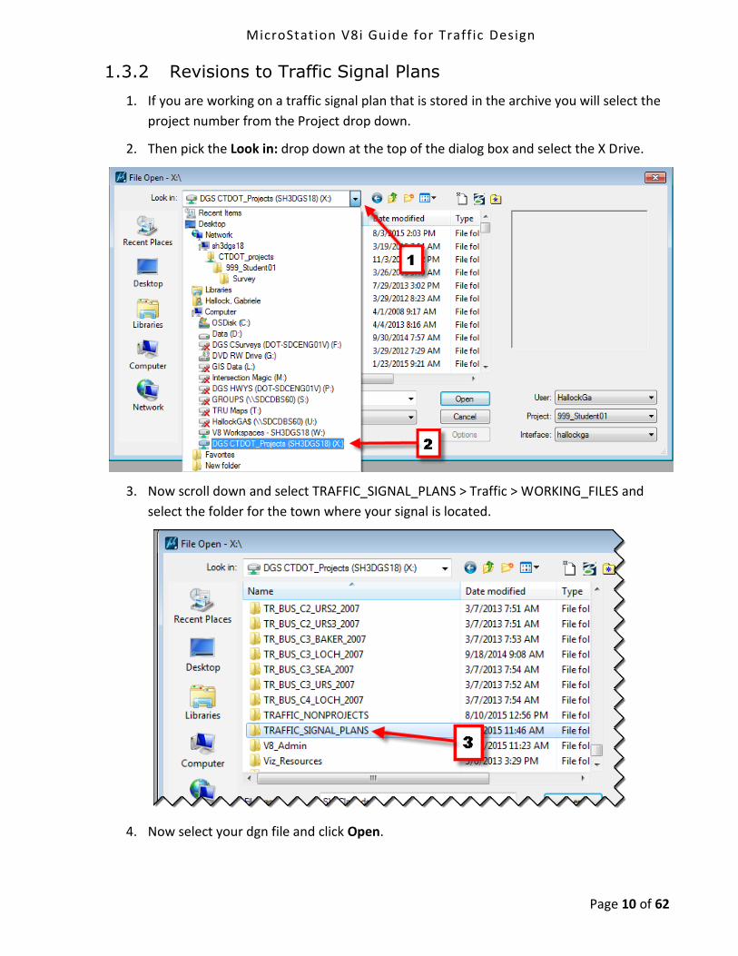
1.3.2 Revisions to Traffic Signal Plans
1. If you are working on a traffic signal plan that is stored in the archive you will select the
project number from the Project drop down.
2. Then pick the Look in: drop down at the top of the dialog box and select the X Drive.
3. Now scroll down and select TRAFFIC_SIGNAL_PLANS > Traffic > WORKING_FILES and
select the folder for the town where your signal is located.
4. Now select your dgn file and click Open.

MicroStation V8i Guide for Traffic Design
Page 11 of 62
1.3.3 Non-Project and Non-Signal CAD Design
1. If you are working on a CAD file that does not have a project number and is not a signal
plan, then select TRAFFIC_NONPROJECTS from the Project drop down.
2. Select the folder with the name of the town where your job is located.
3. Create your dgn files here.

MicroStation V8i Guide for Traffic Design
Page 12 of 62
1.4 Seed Files
A seed file is MircoStation's term for a template. When you select File/New or click the New
icon, MicroStation makes a copy of the selected seed file, places it in your selected project folder and
you give it a new name.
The MicroStation seed files can be found in W:\Workspace\Standards\seed
For Design Models used to layout design features use the seed file
CT_Design_2D_V8i.dgn
For Sheet Files that use a border cell and will contain the annotation use the seed file
CT_Sheet_Civil_2D_V8i.dgn

MicroStation V8i Guide for Traffic Design
Page 13 of 62
Section 2 Design Models
2.1 Creation
1. Once you have gone through Accounting and chosen your project folder go into the folder
where you want your design file to be located. Click on New File icon.
2. On the bottom right, next to the file path for the seed file, click on Browse.
3. Browse to W:\Workspace\Standards\seed\CT_Design_2D_V8i.dgn seed file and click
Open.
4. Type in File name: For files used to develop a design for construction projects use the
following file name TR_MST_SSP_####_####.dgn and Click Save. For non-project study
related you can use any file name.

MicroStation V8i Guide for Traffic Design
Page 14 of 62
5. Select the file you just created and click Open.
6. In the newly created file, Click on Workspace > Preferences, select Reference and Toggle
on Use Color Table.

MicroStation V8i Guide for Traffic Design
Page 15 of 62
7. Next Click on the References button to open the References dialog box.
8. In the References dialog box select Attach Reference icon.
9. Navigate to the Survey folder and reference the Survey *.dgn file, use Survey as Logical
Name and No Nesting for Nested Attachments.
10. Select Attach from the References dialog box again. Navigate to the Highways folder,
then the MSta Design folder and reference the highway design file, use Highway as
Logical Name and No Nesting for Nested Attachments.
11. Select Level Display and turn off desired levels in the reference files.
Select File > Save Settings.
12. You can also use the tool in the Traffic task menu Select Traffic > Getting Started > Set
Design Model Reference Levels.

MicroStation V8i Guide for Traffic Design
Page 16 of 62
2.2 Drawing Tasks
In this section you will draw a lane line for a shoulder, place some signs, place some metal
conduits, and draw a traffic signal assembly. These are just a few examples of the many Traffic
Tools.
2.2.1 Tasks Menu
What is a task?
A task is a set of tools grouped to facilitate a particular job/task. Tasks comprise a command with
the correct symbology for a feature and/or pay item.
If you don’t see the Main Task menu click on “Tools” and toggle on “Tasks”, usually it pops back
to the left side of your MicroStation view.
You can dock it where you want it, by dragging the menu to either left or right, up or down to the
arrows appearing when close to the edge.

MicroStation V8i Guide for Traffic Design
Page 17 of 62
2.2.2 Drawing a Shoulder Line
1. Here is one way to draw a shoulder line. Make sure the Pavement Marking Lines tab is
open on the task bar and then click on Lane Line White.
2. This sets the correct level, color, line style, and weight for a lane line. This tool also
activates the place smart line tool. In this example you won’t be drawing the line, you will
copy the edge of road.

MicroStation V8i Guide for Traffic Design
Page 18 of 62
3. At the top of the task menu select the Manipulate tools and then Move Parallel.
4. Set up the Copy Parallel dialog box as shown above. The top button should be set to
Element because you will be copying an entire element. The Mode is set to Miter. This
mode will lengthen or shorten the element to try to match the shape of the original. The
distance is set to 4 feet. Check Use Active Attributes to create the copy using the active
attributes. Most importantly check Make Copy or else you won’t get a copy.
5. Now click on one of the pink edge of road lines and move the cursor to the inside of the
road and click. Now you should have a shoulder line 4 feet away and parallel to the edge
of road.
MicroStation V8i Guide for Traffic Design
Page 19 of 62
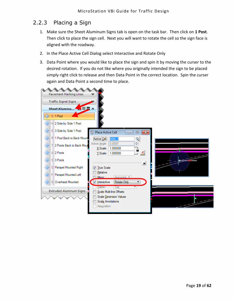
2.2.3 Placing a Sign
1. Make sure the Sheet Aluminum Signs tab is open on the task bar. Then click on 1 Post.
Then click to place the sign cell. Next you will want to rotate the cell so the sign face is
aligned with the roadway.
2. In the Place Active Cell Dialog select Interactive and Rotate Only
3. Data Point where you would like to place the sign and spin it by moving the curser to the
desired rotation. If you do not like where you originally intended the sign to be placed
simply right click to release and then Data Point in the correct location. Spin the curser
again and Data Point a second time to place.

MicroStation V8i Guide for Traffic Design
Page 20 of 62
2.2.4 Placing a Metal Conduit
1. First select the Ground Equipment tab from the Task Menu.
2. Then select the Rigid Metal Conduit tool.

MicroStation V8i Guide for Traffic Design
Page 21 of 62
3. You can place the conduit as straight sections as shown below.
4. Then select Construct Circular Fillet.

MicroStation V8i Guide for Traffic Design
Page 22 of 62
5. Type in a radius of 10 and truncate both.
6. Click one line then the other and an arch will be constructed between the lines.
7. Once you have placed all the segments of the conduit, select the Create Complex Chain
tool to connect all of the segments. Click on each segment and this will redraw the line as
one continuous element.

MicroStation V8i Guide for Traffic Design
Page 23 of 62
2.2.5 Placing a Signal Assembly
1. First place some Steel Span Poles. Select a Steel Span Pole cell then place the poles.
Rotate as needed.
2. Now click on the Span Wire / Mast Arm tool and place the spans or mast arms. Also use
the Span Wire tool and draw lines that will connect from the Spans/mast arms to the
traffic signal face symbols.
3. Select the Traffic Signal Face tools to place the triangle symbols to the line placed in step
3 and clip the lines to the signal face symbols.

MicroStation V8i Guide for Traffic Design
Page 24 of 62
4. Now you are going to use AccuSnap to place the Span Wire Attachment circles at the
intersections of the span lines. If you don’t already have the Snap buttons docked on
your screen go to Settings < Snaps < Button Bar. Then drag the button bar and dock it
where you like it on the screen. Double click on the Intersect Snap to lock it.
Another good choice for snapping is the Key Point Snap. That is usually the snap turned
on by default. That is the second snap from the left. You may want to double click that
snap after placing the circles.
5. Now select the Span Wire Attachment tool from the Task Bar and click on the
intersection of the span lines.

MicroStation V8i Guide for Traffic Design
Page 25 of 62
6. Now select the Trim Multiple tool and set it to Trim.
7. Select the Circle for the cutting edge and click on the ends sticking out of the circle and
click on the line segments inside of the circle.
MicroStation V8i Guide for Traffic Design
Page 26 of 62
Section 3 Sheet Models
3.1 Creation
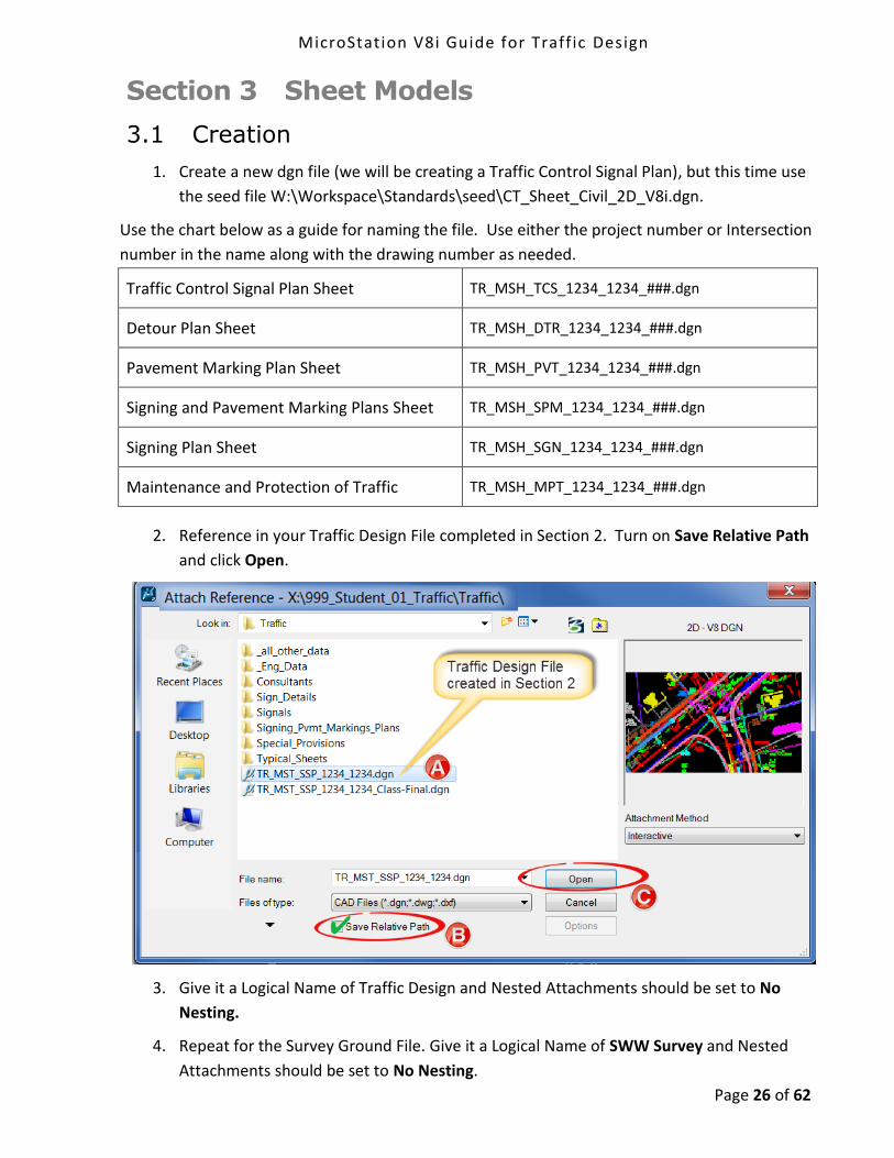
1. Create a new dgn file (we will be creating a Traffic Control Signal Plan), but this time use
the seed file W:\Workspace\Standards\seed\CT_Sheet_Civil_2D_V8i.dgn.
Use the chart below as a guide for naming the file. Use either the project number or Intersection
number in the name along with the drawing number as needed.
Traffic Control Signal Plan Sheet TR_MSH_TCS_1234_1234_###.dgn
Detour Plan Sheet TR_MSH_DTR_1234_1234_###.dgn
Pavement Marking Plan Sheet TR_MSH_PVT_1234_1234_###.dgn
Signing and Pavement Marking Plans Sheet TR_MSH_SPM_1234_1234_###.dgn
Signing Plan Sheet TR_MSH_SGN_1234_1234_###.dgn
Maintenance and Protection of Traffic TR_MSH_MPT_1234_1234_###.dgn
2. Reference in your Traffic Design File completed in Section 2. Turn on Save Relative Path
and click Open.
3. Give it a Logical Name of Traffic Design and Nested Attachments should be set to No
Nesting.
4. Repeat for the Survey Ground File. Give it a Logical Name of SWW Survey and Nested
Attachments should be set to No Nesting.

MicroStation V8i Guide for Traffic Design
Page 27 of 62
5. If required repeat for the Highway Design file. Give it a Logical Name of Highway and
Nested Attachments should be set to No Nesting.
6. Rotate view as needed. Select the Method 2 Points and data point following the prompts
to Define your X axis.
7. Access the Sheet Composition Task. Now you will see another set of tasks, all related to
working on Traffic Sheets.

MicroStation V8i Guide for Traffic Design
Page 28 of 62

MicroStation V8i Guide for Traffic Design
Page 29 of 62
3.2 Attaching a Border and Clipping the References
Major changes have been made to the signal border, there were four to choose from and now it
has been combined into one. All other types of sheets will use the general plan sheet border.
1. Before clipping your Reference files copy in the North Arrow from the Survey Ground file.
2. Go to the Setup and Borders Task Menu and select a border cell and place it. When
working on a Signal Plan as we are, you will also need to attach the Detector Chart,
Program Chart and Phase Chart. These are cells that can be attached using the Sheet
Composition Task. These cells will be placed under the Signal Border Movement Diagram
from left to right in the order below.
PLEASE NOTE:
Do not use the Drop Element command on the cell borders, this will cause multiple issues.

MicroStation V8i Guide for Traffic Design
Page 30 of 62
3. Select the Create Clipping Boundary Shape on the same task menu. Place a shape
around what you want inside your Border
4. Now go to the References dialog box and select all of the reference files. Right click on
them and select Clip Boundary.
5. Select the Method Element and data point on the element that was placed in step 3.
PLEASE NOTE:
If you are unable to fit the entire design within one border, make additional dgn files;
one file for each sheet. You can also reference all the files in again (Traffic Design
Highway Design and the Survey Ground file) and then move them together to a blank
area on the sheet and clip them as needed. Do not copy in these reference files.

MicroStation V8i Guide for Traffic Design
Page 31 of 62
6. Click on the Models Icon.
7. Use the Sheet Boundary tools to move your Transient Shape (Plotting Boundary) into
place around the Border Cell. Use the Move and Rotate tools shown below and follow
the MicroStation prompts for accurate placement.

MicroStation V8i Guide for Traffic Design
Page 32 of 62
8. Use the Edit Tags tools to fill out the Blue Town, Drawing Title, Project Number and
Drawing No.. Use the Data Field and Edit Text tools to complete edit the green text.

MicroStation V8i Guide for Traffic Design
Page 33 of 62
3.3 Adjusting the Appearance of the Sheet
3.3.1 Update the Display Sequence of Reference Files
1. In the references dialog box click on Settings > Update Sequence. The sequence is the
order in which MicroStation loads the files. When a file is listed at the top of the
sequence, that means it is loaded first and will appear on the bottom as if it is below the
other files.
2. Using the Update Sequence… tools (up and down arrows) move the files either up or
down to the desired location(s). The Active Design file should be the last file in the
update sequence, meaning this is the last layer the printer/plotter prints, see update
sequence graphic. When finished click Ok.
MicroStation V8i Guide for Traffic Design
Page 34 of 62
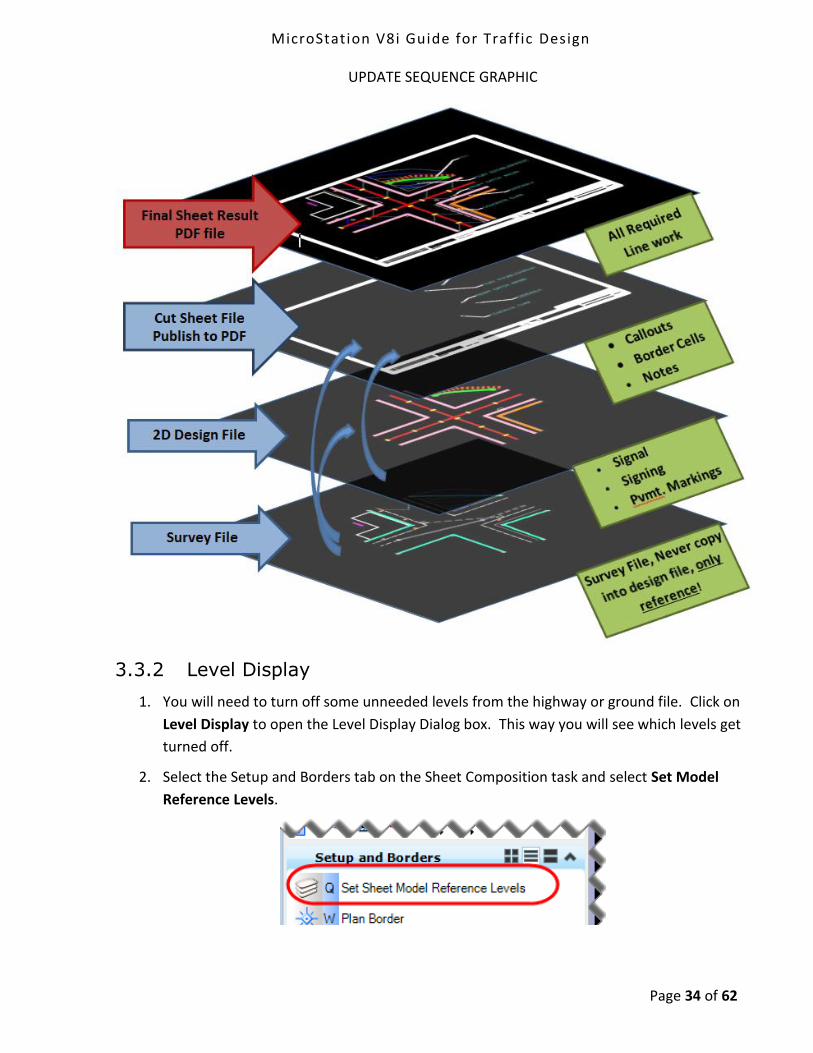
UPDATE SEQUENCE GRAPHIC
3.3.2 Level Display
1. You will need to turn off some unneeded levels from the highway or ground file. Click on
Level Display to open the Level Display Dialog box. This way you will see which levels get
turned off.
2. Select the Setup and Borders tab on the Sheet Composition task and select Set Model
Reference Levels.

MicroStation V8i Guide for Traffic Design
Page 35 of 62
3.4 Pull Down Menu
There have been many changes made to the drop down menu. The drop down menu formerly
had a section called Traffic and a section called Signing. These sections have been renamed to
Traffic Notes and Sign Details. The items from the drop down menu that represent physical
objects, such as aluminum signs or pavement markings, were relocated to the Task Menu. The
items that are graphics or text used for annotation, such as notes or sign details, were left in the
drop down menu.
3.5 Sheet Composition Task
In this section you will be using some of the new tools that were created for making sheets.
There are two menus for Annotation; General and Signal Plan. The General Annotation has a
larger font size and the Signal Plan Annotation has a smaller font size. The Sheet Composition
Task can be found using this path in the task menu Traffic > Sheet Composition.

MicroStation V8i Guide for Traffic Design
Page 36 of 62
3.5.1 General Call Outs
1. Select the General Annotation or Signal Plan Annotation tab on the Task Menu.

MicroStation V8i Guide for Traffic Design
Page 37 of 62
2. Select the Call Out tool. In the Place Note Dialog box make sure the left tool ‘Place Note’
is active and Start At is set to Terminator.
3. Type in the note you wish to place in the text box that appears.
4. Click on the item you wish to annotate and then click in the location you want the note to
be located. Right click to place the call out.
3.5.2 Circle and Hexagon Text Frames
1. Typically on a Traffic Signal Plan signs are annotated with a circle text frame. On the Task
Menu make sure you are in the Signal Plan Annotation tab. Then select the Circle Text
Frame tool.
2. Make sure the Place Note dialog box that comes up is set to Place Callout.

MicroStation V8i Guide for Traffic Design
Page 38 of 62
3. In the Text Editor dialog box type in the letter for the callout. Then click on the screen to
place the callout bubble.
4. Construction notes use a hexagon text frame. You should follow the same procedure
shown above, but choose the Hexagon Text Frame tool instead.

MicroStation V8i Guide for Traffic Design
Page 39 of 62
3.5.3 Labeling and Notes
Select General Annotation and browse through the labeling and notes options.
1. The General Note Title uses larger text than the General Notes.
2. The Approx. R.O.W. text will appear in the dialog box automatically and you choose the
method of placement for example: Below or Above Element.

MicroStation V8i Guide for Traffic Design
Page 40 of 62
3. Some more examples of annotations.

MicroStation V8i Guide for Traffic Design
Page 41 of 62
3.5.4 Labeling the Traffic Signal Faces
1. Even though the labeling of the traffic signal faces is annotation, it should be placed in the traffic signal plan. This way you can make a blow up to more clearly show the intersection and the signal face annotation will scale along with the rest of the design file.
2. Highlight the Traffic Signal Plan file in the References dialog box.
3. Right click on the reference and select Activate.
4. Now the elements in the active reference appear in their normal colors, but everything else appears grey. You can now manipulate the reference file and the elements within it.
MicroStation V8i Guide for Traffic Design
Page 42 of 62
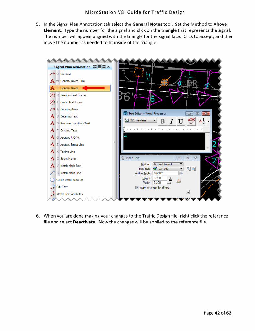
5. In the Signal Plan Annotation tab select the General Notes tool. Set the Method to Above Element. Type the number for the signal and click on the triangle that represents the signal. The number will appear aligned with the triangle for the signal face. Click to accept, and then move the number as needed to fit inside of the triangle.
6. When you are done making your changes to the Traffic Design file, right click the reference file and select Deactivate. Now the changes will be applied to the reference file.
MicroStation V8i Guide for Traffic Design
Page 43 of 62
3.5.5 Linear Dimensioning
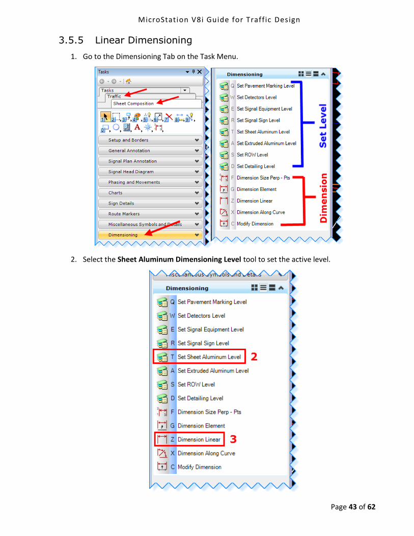
1. Go to the Dimensioning Tab on the Task Menu.
2. Select the Sheet Aluminum Dimensioning Level tool to set the active level.
MicroStation V8i Guide for Traffic Design
Page 44 of 62
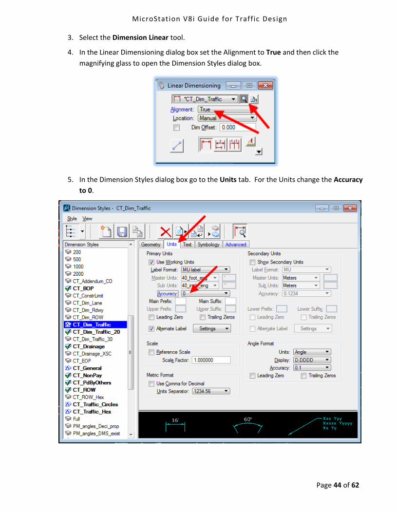
3. Select the Dimension Linear tool.
4. In the Linear Dimensioning dialog box set the Alignment to True and then click the
magnifying glass to open the Dimension Styles dialog box.
5. In the Dimension Styles dialog box go to the Units tab. For the Units change the Accuracy
to 0.

MicroStation V8i Guide for Traffic Design
Page 45 of 62
6. Now click on the object you are using for a reference (1 – catch basin), and then click on
the sign (2). Next click to determine how far the dimension will extend (3). Click one
more time to place the number value for the dimension (4). At this point you can right
click to finish using the tool, or if you have another sign farther down the alignment you
can click to that sign and an additional dimension will be drawn.

MicroStation V8i Guide for Traffic Design
Page 46 of 62
3.5.6 Dimensioning Length Along a Curve
1. First click on the tool to select the level of the object you are dimensioning.
2. Then click on Dimension Along Curve.
3. Click the magnifying glass to open the Dimension Styles dialog box.

MicroStation V8i Guide for Traffic Design
Page 47 of 62
4. In the Dimension Style dialog box, go to the Units tab. Set the Units Accuracy to 0 and set
Angle Format – Units: to Length.
5. Click on the two points on the curve you wish to dimension. Then click again to select the
length of the dimension lines. Click again to place the number. Then right click to accept
the dimensioning.

MicroStation V8i Guide for Traffic Design
Page 48 of 62
3.5.7 Sign Details
1. First select the needed sign detail from the Sign Details drop down menu and place it at
desired location on sheet.
2. Next select the Bubble or Block cell for Sheet Aluminum or Extruded Aluminum
depending on which one you need and place it next to Sign Detail.

MicroStation V8i Guide for Traffic Design
Page 49 of 62
3. Select the Arc tool for either sheet or extruded aluminum and place it to connect the
detail and call out. For Method select Start, Mid, End and follow the prompts for
placement.
4. Then select the Line tool and connect the call out to the sign you are detailing.
5. Select Fill in Single Enter Data Field in the call out bubble/location box.
6. Add Text and Edit Text as needed
7. Add all elements of the sign detail to a Graphic Group

MicroStation V8i Guide for Traffic Design
Page 50 of 62
3.5.8 Detail Blow ups
When doing blow up details it is better to reference the layout model(s), and move and scale,
rather than to copy the features into the sheet model, this way the blow-up stays current with
design changes.
1. Open the References dialog box. Select the Layout Model(s) and copy the attachments,
Right click and select Copy.
2. Toggle on as shown below and data point in View 1 and then again to where you would
like to move them and reset to accept.

MicroStation V8i Guide for Traffic Design
Page 51 of 62
3. Select the copied reference attachments, right click and select Scale, or click on the Scale
Reference icon. Make sure all needed files are highlighted.
4. In the Scale Reference box input a scale factor and follow the prompts to accept.
5. In the Sheet Composition Task select Signal Plan Annotation > Circle Detail Blow Up
and place a circle around what you would like to detail. This will serve as the clipping
boundary. In the reference dialog box select the files you need clipped, right click, and
select Clip Boundary. Select the element method and click on the circle.

MicroStation V8i Guide for Traffic Design
Page 52 of 62
6. Use the tools Circle Detail Blow Up, Detailing Note, and Detailing Text to label the
detail. Turn Off levels as needed.
7. Move the reference files in the detail around as needed and adjust the size and
placement of the clipping circle.
8. To dimension the Detail you will need to select the correct dimension style. The base
scale for all tools in Traffic Dimensioning Tasks is 1in = 40 ft, if you scaled the reference
files by 2 you will need to set a Dimension Style that uses 1 in = 20 ft.
9. Select Element > Dimension Styles, select CT_DIM_Traffic_20 (if you scaled the
references by 1.5 use CT_Dim_Traffic_30)
10. Use the Dimensioning tools to dimension the detail.
11. Select Detailing Text to label the scale of the detail.

MicroStation V8i Guide for Traffic Design
Page 53 of 62
Section 4 Additional Workflows and Help
4.1 Screening and Level Display Automation
4.1.1 Set Reference Levels Tools
The Traffic Task includes two tools to help automate turning on and off levels and adjusting their
appearance in your reference files. The tool shown below on the left is to be used when you are
in a design model laying out the features. The tool shown below on the right is to be used when
you are in a cut sheet (sheet model) doing the annotation. This tool also overrides the level
symbology of the reference files to the preferred look for PDF creation.
PLEASE NOTE:
Do not use nesting when referencing, if you would like to be able to utilize these
tools.
MicroStation V8i Guide for Traffic Design
Page 54 of 62
4.1.2 Reference File Logical Names
The correct logical name is needed for the Set Reference Levels Tools to work properly. If you
don’t put these names in correctly, you will not get the desired outcome when running the tools.
It should be noted that these tools only turn on and off Traffic, Survey and Highway levels, other
discipline reference files level will need to be turned on and off manually in the Level Display
dialog box.
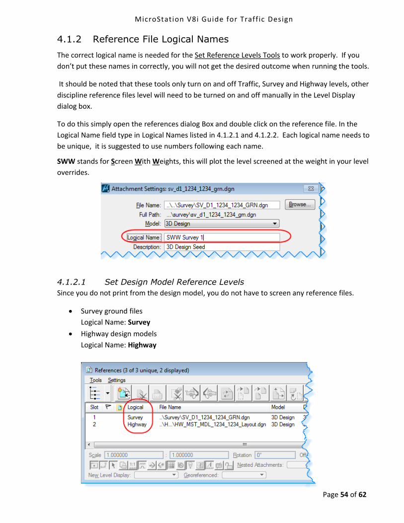
To do this simply open the references dialog Box and double click on the reference file. In the
Logical Name field type in Logical Names listed in 4.1.2.1 and 4.1.2.2. Each logical name needs to
be unique, it is suggested to use numbers following each name.
SWW stands for Screen With Weights, this will plot the level screened at the weight in your level
overrides.
4.1.2.1 Set Design Model Reference Levels
Since you do not print from the design model, you do not have to screen any reference files.
Survey ground files
Logical Name: Survey
Highway design models
Logical Name: Highway
MicroStation V8i Guide for Traffic Design
Page 55 of 62
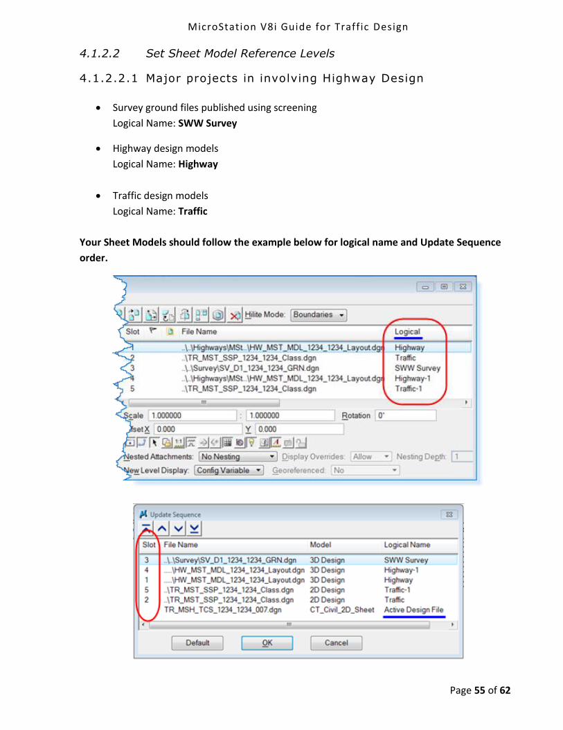
4.1.2.2 Set Sheet Model Reference Levels
4.1.2.2.1 Major projects in involving Highway Design
Survey ground files published using screening
Logical Name: SWW Survey
Highway design models
Logical Name: Highway
Traffic design models
Logical Name: Traffic
Your Sheet Models should follow the example below for logical name and Update Sequence
order.

MicroStation V8i Guide for Traffic Design
Page 56 of 62
4.1.2.2.2 Signal only with no major roadway redesign
The Survey file will be referenced in twice. The Existing Edge of Road, Drainage Structures,
Guiderail, Utility Poles and related text will be turned on and not be screened in one reference
file. All the other levels will be screened in the other reference file.
Survey ground files published using screening
Logical Name: SWW Survey
Survey ground files with levels on that will not be screened.
Logical Name: Bold
Traffic design models
Logical Name: Traffic
Your Sheet Models should follow the example below for logical name and Update Sequence
order.

MicroStation V8i Guide for Traffic Design
Page 57 of 62
4.2 Underground Utilities and Drainage Pipes
In MicroStation the “Set Reference Levels” tool is used when in a cut sheet (Sheet Model) and it
will leave the Underground and Drainage levels on. Users will turn these levels off in Bluebeam
Revu before getting the plan set signed. Below is the procedure for turning off levels in
Bluebeam Revu.
1. Click on the Layers Icon.
2. Select the levels you would like to be off by clicking on the eye next to each level and
you will be left with a empty box.
3. When you are done turning off all the needed levels, click the arrow to the right of
and select Save Configuration.

MicroStation V8i Guide for Traffic Design
Page 58 of 62
4. Click on the Save Icon before closing the file.

MicroStation V8i Guide for Traffic Design
Page 59 of 62
4.3 User Preference File
1. On the MicroStation Main Menu select Workspace > Preferences.
2. Your Windows login name should appear in the blue title of the Preferences Dialog box
and the Name of Preferences field should match the version of MicroStation you are
running. To check the version you are running close the Preferences Dialog box and
select Help > About MicroStation.
3. If your login name in the blue portion of the preference both did not match your windows
login go back to 1.2 Creating a User Configuration File. It is imperative that you follow
these directions and you use your Windows Login Name to create your MicroStation User
and Interface.
MicroStation V8i Guide for Traffic Design
Page 60 of 62
4. If the version Number doesn’t match exit MicroStation. Open Windows Explorer and navigate to the location (Windows 7):
D:\Users\YourUserName\AppData\Local\Bentley\MicroStation\8.11\irRFESEEaUk7nwy13ZRxlQ\prefs
Find your user name with the UPF extension and delete it. Open MicroStation back up
making sure you use your MicroStation Interface and user names and immediately close
MicroStation. The file you just deleted will get automatically recreated. Open
MicroStation one more time and check the Name of the Preference and the version
numbers should now match.
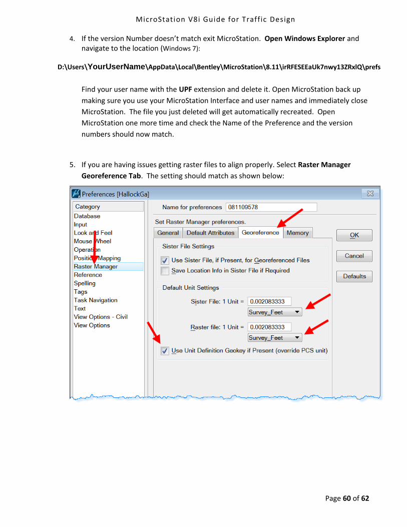
5. If you are having issues getting raster files to align properly. Select Raster Manager
Georeference Tab. The setting should match as shown below:

MicroStation V8i Guide for Traffic Design
Page 61 of 62
4.4 Links
This Document MicroStation Workflows

MicroStation V8i Guide for Traffic Design
Page 62 of 62
CTDOT - SELECTseries DDE (Digital Design Environment)
http://www.ct.gov/dot/cwp/view.asp?a=3194&q=483668&PM=1
This link will give you access to all AEC Applications:
CTDOT Guides:
MicroStation for Highway Design
MicroStation for Traffic engineers (This Guide)
InRoads Guide for Designers
InRoads Guide for Surveyors
Miscellaneous Workflows:
USGS Permit Plates
Project Explorer & managing Drawing No.
Data Acquisition Tools
StormCAD SS5 for MicroStation
InRoads for Survey for designers
InRoads Export to HEC-RAS
Earth Exploration
Publishing and Printing
Publishing MicroStation content to PDF
Printing PDF Engineering content
AASHTO Trnsport (integrated construction contract management system)
http://www.ct.gov/dot/cwp/view.asp?a=3194&q=484952