microstrip linear phased array for smart antenna...
TRANSCRIPT

International Journal of Electronics Engineering, 4 (1), 2012, pp. 39– 42
Microstrip Linear Phased Array forSmart Antenna Applications
Md. Bakhar1, Vani R. M.2 & P. V. Hunagund2
1Department of E&CE, G.N.D. Engineering College, Bidar-585403, India2Department of PG Studies & Research Center, Gulbarga University, Gulbarga, India
(E-mail: [email protected] [email protected])
Abstract: In this paper, we have proposed microstrip phase antenna arrays for smart antenna applications designed at 2.7GHzfrequency. The antenna array simulations are carried out by using IE3D software. The simulated antennas are fabricatedusing glass epoxy substrate with dielectric constant 4.4. The fabricated arrays are tested practically for the return losses,radiation patterns and gain measurements. Both the simulation and practical results are compared and found that they are ingood agreement. Details of the antenna array design are presented and experimental results are discussed. Phased antennaarrays are useful for many types of applications such as traffic control and collision avoidance radars, smart base stationantennas for WLAN and cellular communication.
Keywords: Microstrip phased arrays, beam steering, transmission line phase shifter.
� Serials Publications, ISSN : 0973-7383
1. INTRODUCTION
Many antenna system applications for wirelesscommunication require that the direction of the main beamlobe be changed with time. This can be achieved by phasearray antennas which can sweep the direction of the beamby varying electronically the phase of the radiating elements,thereby producing moving a pattern electronically with higheffectiveness managing to get minimum side lobe levels andnarrow beam widths. Schematic illustration of a phased arrayantenna is shown in Figure 1. It consists of power distributionnetwork, phase shifters and antenna elements. Wire antenna,microstrip patches, horn antenna and wave guides are varioustypes of antennas that are used. A large number of antennaelements were needed to construct the array to achieve anarrow beam width or considerable scanning range with highangle resolution. Phase shifters are classified as mechanicalphase shifters, ferrite phase shifters, semiconductor devicephase shifters and transmission line phase shifters. Powerdividers are used for splitting microwave signals to feed theradiating elements [1].
In this paper, the investigation on amount ofbeamsteering of main beam by changing the length oftransmission line is presented. We found practically thatthere is an increase in gain by factor 2 with the increase inarray elements and also demonstrated 5o beamsteering of amain beam towards right with the L/6 length of transmissionline from first element (5L/6 from second element).Similarly, there is a 5o beamsteering towards left with areverse condition.
Phased array antenna can be used for beamsteeringapplications in smart antennas, submarine communication
and air borne mobile communication. Higher data rates upto and beyond 1Mbps and over long distances (around theglobe) is possible with INSAT series having S-band mobilecommunication pay load for submarines. Considerableresearch has been conducted by several organizationsand individuals because of advances in phased arrayantennas and its underlying signal processing algorithmstheoretically [2][3].
2. DESIGN OF MICROSTRIP ARRAY ANTENNA
Microstrip patch antennas are important as single radiatingelements but their major advantages are realized inapplication requiring moderate size arrays. The primaryradiator microstrip antenna is designed with frequencyf = 2.7GHz which gives single element microstrip antenna(SEMA) as shown in Figure 2. The dimensions of the patchare calculated using formulae found in [4]. Single patch isextended to two element microstrip array (TEMA) shownin Figure 3 and extended to four element microstrip array
Figure 1: Phased Array Antenna
40 International Journal of Electronics Engineering
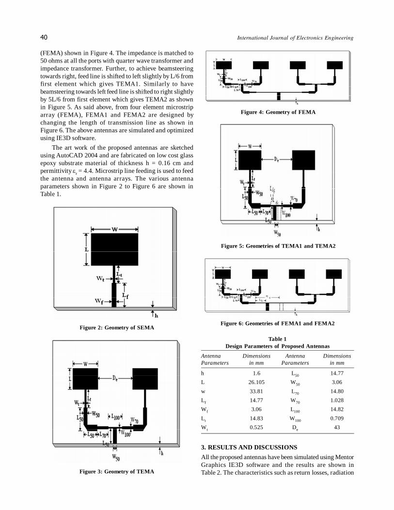
(FEMA) shown in Figure 4. The impedance is matched to50 ohms at all the ports with quarter wave transformer andimpedance transformer. Further, to achieve beamsteeringtowards right, feed line is shifted to left slightly by L/6 fromfirst element which gives TEMA1. Similarly to havebeamsteering towards left feed line is shifted to right slightlyby 5L/6 from first element which gives TEMA2 as shownin Figure 5. As said above, from four element microstriparray (FEMA), FEMA1 and FEMA2 are designed bychanging the length of transmission line as shown inFigure 6. The above antennas are simulated and optimizedusing IE3D software.
The art work of the proposed antennas are sketchedusing AutoCAD 2004 and are fabricated on low cost glassepoxy substrate material of thickness h = 0.16 cm andpermittivity �r = 4.4. Microstrip line feeding is used to feedthe antenna and antenna arrays. The various antennaparameters shown in Figure 2 to Figure 6 are shown inTable 1.
Table 1Design Parameters of Proposed Antennas
Antenna Dimensions Antenna DimensionsParameters in mm Parameters in mm
h 1.6 L50 14.77
L 26.105 W50 3.06
w 33.81 L70 14.80
Lf 14.77 W70 1.028
Wf 3.06 L100 14.82
Lt 14.83 W100 0.709
Wt 0.525 De 43
3. RESULTS AND DISCUSSIONS
All the proposed antennas have been simulated using MentorGraphics IE3D software and the results are shown inTable 2. The characteristics such as return losses, radiation
Figure 2: Geometry of SEMA
Figure 3: Geometry of TEMA
Figure 4: Geometry of FEMA
Figure 5: Geometries of TEMA1 and TEMA2
Figure 6: Geometries of FEMA1 and FEMA2
Microstrip Linear Phased Array for Smart Antenna Applications 41
patterns and gain measurements of all proposed configurationshave been obtained through simulation and also verifiedexperimentally by using Vector Network Analyzer (Rohde& Schwarz, Germany make ZVK model 1127.8651). Thesimulated and measured results are in good agreement.
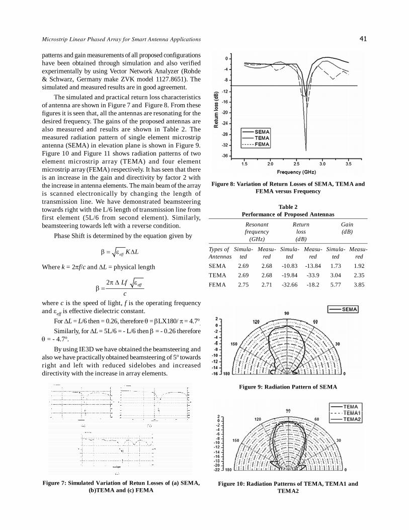
The simulated and practical return loss characteristicsof antenna are shown in Figure 7 and Figure 8. From thesefigures it is seen that, all the antennas are resonating for thedesired frequency. The gains of the proposed antennas arealso measured and results are shown in Table 2. Themeasured radiation pattern of single element microstripantenna (SEMA) in elevation plane is shown in Figure 9.Figure 10 and Figure 11 shows radiation patterns of twoelement microstrip array (TEMA) and four elementmicrostrip array (FEMA) respectively. It has seen that thereis an increase in the gain and directivity by factor 2 withthe increase in antenna elements. The main beam of the arrayis scanned electronically by changing the length oftransmission line. We have demonstrated beamsteeringtowards right with the L/6 length of transmission line fromfirst element (5L/6 from second element). Similarly,beamsteering towards left with a reverse condition.
Phase Shift is determined by the equation given by
eff K L� � � �
Where k = 2�f/c and �L = physical length
2 effLf
c
� � �� �
where c is the speed of light, f is the operating frequencyand �eff is effective dielectric constant.
For �L = L/6 then = 0.26, therefore � = �LX180/ � = 4.7o.
Similarly, for �L = 5L/6 = - L/6 then � = - 0.26 therefore� = - 4.7o.
By using IE3D we have obtained the beamsteering andalso we have practically obtained beamsteering of 5o towardsright and left with reduced sidelobes and increaseddirectivity with the increase in array elements.
Table 2Performance of Proposed Antennas
Resonant Return Gainfrequency loss (dB)
(GHz) (dB)
Types of Simula- Measu- Simula- Measu- Simula- Measu-Antennas ted red ted red ted red
SEMA 2.69 2.68 -10.83 -13.84 1.73 1.92
TEMA 2.69 2.68 -19.84 -33.9 3.04 2.35
FEMA 2.75 2.71 -32.66 -18.2 5.77 3.85
Figure 7: Simulated Variation of Retun Losses of (a) SEMA,(b)TEMA and (c) FEMA
Figure 8: Variation of Return Losses of SEMA, TEMA andFEMA versus Frequency
Figure 9: Radiation Pattern of SEMA
Figure 10: Radiation Patterns of TEMA, TEMA1 andTEMA2

42 International Journal of Electronics Engineering
4. CONCLUSION
In this paper we demonstrated a phased array concept byvarying the length of the transmission line. The resultsobtained through simulation and experiments of microstriparrays are discussed. All the proposed antennas arefabricated and tested practically. Both the results are goodin agreements. Theoretical and practical beamsteering angleare also good in agreement. The designed antenna can beused for phased array applications in S-band i.e. at 2.7GHz.The integrating phased array antenna with digital signalprocessing (DSP) algorithms may find application in thesmart antenna systems.
Figure 11: Radiation Patterns of FEMA, FEMA1 andFEMA2
ACKNOWLEDGMENTS
The authors acknowledge their thanks to UGC, New Delhifor sanctioning the IE3D software under Major researchproject which is most useful and reliable for designingmicrostrip antennas. The authors also thank the authoritiesof Department of Science and Technology (DST), Govt. ofIndia, New Delhi, for sanctioning the Network Analyzerunder the FIST project to the Department of AppliedElectronics, Gulbarga University, Gulbarga.
REFERENCES[1] J. Ehmouda.z. Briqech and A. Amer, “Steered Microstrip
Phased Array Antennas”, World Academy of Science,Engineering and Technology, Vol. 49, 2009, pp. 319-322.
[2] Alison Brown and David Morley (Navsys Corp) (2001), “TestResults of a Seven Element Small Controlled ReceptionPatterns Antenna”, Proceedings of ION GPS2001, Salt LakeCity, Utah, pp. 1-8.
[3] A.O. Boukalov and S. G. Haggman, “System Aspects of SmartAntenna Technology in Cellular Wireless Communications-An Overview”, IEEE Transactions on Microwave Theory andTechniques, Vol. 48, 2000, pp. 919-929.
[4] Constantine A. Balanis, Antenna Theory – Analysis andDesign, John Wiley and Sons, Singapore, 2002.