microtec p.o. box 60337 sunnyvale, ca 94088 408-733- · pdf filesic sip sis sm soc sop sos...
TRANSCRIPT

8080/8085 SIMULATOR MANUAL
Microtec P.O. Box 60337 Sunnyvale, CA 94088 408-733-2919

TABLE OF CONTENTS
1.0 INTRODUCTION 1-1
2.0 THE SIMULATOR 2-1
OVerview 2-1 Processor Model 2-3 Simulation Modes 2-4 Program Operation 2-5 System Input/Output 2-7 Addressing 2-8 Input/Outp~t Simulation 2-9 Interrupt Simulation 2-13 Standard Display Line 2-14 CharacteJ::' Set 2-16 Constants 2-17 Symbols· 2-18 Program Counter 2-20 Expressions 2-20 Range Lists 2-21
3.0 SIMULATOR COMMANDS 3-1
Comment 3-2 BASE 3-3 BP 3-4 NBP 3-4 DATA 3-5 MDAT 3-5 SDAT 3-5 DC 3-7 DEL 3-8 DH 3-9 Dr 3-10 DIN 3-10 DO 3-10 DOUT 3-10 D 3-11 DM 3-11 DIM 3-12 DSYM 3-13 E 3-14 EA 3-14 FI 3-15 FIN 3-15 FO 3-15 FOUT 3-15 FORM 3-16 FM 3-17

H IB IC IP IS INT NINT L LS LI MIB MIC MIP MIS MaC MOP MaS OC OP as PRO· NPRO R RD RE RED RES RET s SET SI SIN so . SOUT SIB SIC SIP SIS SM SOC soP SOS SSYM T TA TB TR NTR TYPE W X Single Step Execution
3-18 3-19 3-19 3-19 3-19 3-22 3-22 3-24 3-24 3-26 3-27 3-27 3-27 3-27 3-29 3-29 3-29 3-31 3-31 3-31 3-33 3-33 3-34 3-34 3-34 3-34 3-36 3-37 3-38 3-38 3-40 3-40 3-40 3-40 3-42 3"':42 3-42 3-42 3-44 3-46 3-46 3-46 3-47 3-48 3-48 . 3-48 3-49 3-49 3-50 3-51 3-52 3-53

4.0 SIMULATOR EXAMPLES 4-1
Sample Simulation 4-1 Test Program 4-1
5.0 APPENDICES 5-1
A - Simulator Messages 5-1 B - Command Summary 5-4 C - Object Module Format 5-7 D - Instruction Opcode Summary 5-9 E - Hexadecimal-Decimal Table 5-12

INTRODUCTION
Microtec has developed an Interactive Simulator for the 8080/8085
microprocessor. The Simulator program is written in FORTRAN IV to
achieve compatibility with most computer systems. The program is
approximately 4200 FORTRAN statements in length, twenty percent of
which are comments. The program is written in ANSI standard FORTRAN IV
and no facility peculiar to anyone computer was utilized. This was
done in order to eliminate FORTRAN compatibility problems. The
program is modular and may be executed in an overlay mode should
memory restrictions make that necessary.
Although the Simulator is most effective in an interactive
environment, '~'it may also be used in a batch mode.
The program simulates all aspects of the microprocessor,
including interrupts. The full 64K byte microprocessor memory is
simulated. The Simulator provides for the unlimited setting of
instruction breakpoints and the ability to trace or single step the
execution of each instruction. A very extensive I/O capability
is provide~ that allows the user to perform I/O simulation inter
actively or from files and Data Tables. Symbolic debugging is also
provided; the Simulator can read in symbol values from the assembler,
and the user may then use these symbols as command arguments instead
of absolute addresses.
This manual provides the information pertinent to the operation
and use of the Simulator, but it does not describe programming tech
niques or the operation of the 8080/8085 microprocessor. The reader
may consult the manufacturer's literature for this information.
1-1

THE SIMULATOR
OVerview
This program simulates the operation of the 8080/8085 microprocessor
by implem.enting, in software, the registers and logic control functions
of the actual microprocessor. Like the actual microprocessor, the
Simulator's simulated memory must be loaded with an object module
which contains the program to be debugged. The Load or LS command
is used to do this. The object program may be generated through use
of ariyappropriate. 'Assembler Program,. but it mliIstJ be in standard
Intel Hexadecimal format (see' Appendix C). Microtec's MASM80
Assembler will perform this function.
After the object module has been loaded, the user may use the
Simulator commands to initialize the various registers and status
bits. The RES command may be used to simulate an actual microprocessor
Reset, or the simulated Program Counter may be set to a specific
address to debug a particular subroutine. Simulation is initiated
through use of the !xecute or ~race commands. When program execution
begins, the Simulator fetches the instruction pointed to by the
Program Counter from the simulated memory and executes it. Memory
Registers and Status Bits are then changed to reflect the results
of the instruction execution.
The Simulator offers several advantages over other methods of
program debugging. One of the most obvious ones is that program
debugging may be performed before the hardware is actually built, or
when it is not available because someone else is using it to debug
his program. Another advantage of the Simulator is that program
execution can be controlled precisely. Microprocessor registers
and flags, not normally accessable, may be examined and modified. By
using appropriate commands, the user may trace program flow, .examine
and modify memory locations, feed test data to input ports, view
output data, and as a result, determine the correct operation of
the program under test.

Another useful feature implemented in the Simulator is symbolic
debugging. Symbols (labels) from the ,Assembly program may be read
into the Simulator. The symbols may then be used as command argu
ments when perfo~ing functions such as setting breakpoints. This
reduces the need to refer to absolute addresses, especially helpful
when debugging code written in a higher level language'.
The program can be executed in a batch or interactive mode.
Provision is made for extensive Input/Output capability with the
host ,computer. Commands may be read from disk files or any logical
device (card reader) as well as from the controlling terminal.
Simulator output may be written to a disk file or any logical
device (line printer) as well as to the controlling terminal.
2-2

Processor Model
As previously mentioned, the Simulator has internal variables
and arrays that correspond to all of the microprocessor registers
and status bits. These elements may be initialized through use
of the Simulator's SET Command.
The full 64K word microprocessor memory is simulated and
kept on a disk file. However, segments or pages of the memory that
are being accessed are kept in an array in main memory. By only
keeping the pages being accessed in main memory, the size of the
simulation program on the host computer is kept down to a reasonable
limit. A multi-page scheme keeps disk page swapping to a minimum,
allowing rapid Simulator execution.
Memory may be made to have the characteristics of Read Only
Memory (ROM) through use of the Protect Command. Protected memory
may not be written to. The Protect Command description discusses
this feature further.
There is also an Input/Output memory inside the Simulator
that 'holds the last value read from an Input Port and the last
value written to an Output Port. The output values are placed in
this array as well as written to the file or logical device speci
fied by the Output Port Commands. Likewise, data values written to
and read from memory mapped I/O ports are saved in the corresponding
memory locations as well as written to the file or logical device
specified. The last values read from and written to the serial port
are saved and may be examined with the DIM command.
Inputs on the Reset and Interrupt Pins may be simulated through
use of the Reset and Interrupt Commands. Further details are given
in the command explanations.
The Simulator keeps a cumulative cycle count of the total number
of microprocessor cycles executed. This count may be used to calculate
routine execution times. The SET command may be used to initialize
this count.
2-3
Simulation Modes
The following terms describe those conditions or modes in which
the Simulator operates and which are referred to throughout this
manual. Modes are not exclusive. The Simulator may be in the
Command Mode and the Read Mode.
Command Mode - the program is considered to be in the command
mode whenever it is requesting and executing user input
commands. It leaves the command mode only when a command
is recognized that requires instruction execution.
Execute Mode - this mode is entered from the command mode.
Any of the following commands cause the Simulator to enter the
execute mode: T, TA, TB, E, EA. When simulated program
execution is complete, the command mode is returned to. Also,
any errors that occur during the execution mode will cause the
program to return to the command mode.
Read Mode - the Simulator enters the read mode with respect
to I/O input assignments whenever the user specifies a
R, RO, RE, or RED command to change the current command
input device. Note that the program is said to be in the read
mode even if the device assignment specified in one of the
read commands is the standard input device.
Write Mode - the Simulator enters the write mode with respect
to I/O output assignments whenever the user specifies the W
command. This is the case even if the device assignment
specified in the command is the standard output device.
Standard I/O refers to those I/O device assignments which were
defined in the program at compile time. They are the I/O device
assignments that will be used when the program is first executed.
2-4

Program Operation
When the Simulator is executed, a header is printed on the
standard output device (usually a terminal) indicating that the
Simulator has been entered. Commands are initially read from this
device but may be read from other devices or files through use of the
"R" and "RE" commands. When a command is entered, it is checked
for validity and then executed. Any output (trace information,
I/O messages, etc.) is written to the standard output device or
to an alternate I/O device or file if specified by a "w" command.
If an error occurs during command interpretation or execution,
an appropriate error message will be written to the current output
device and to the standard output device (usually a CRT terminal in
the -interactive mode). The current output device could be a line
printer. An error will also cause all I/O device assignments to
be returned to the "standard I/O devices." This means that if an
error occurs after an "R" or "RE" command has been specified causing
commands to be read from an alternate device, the program will
return to reading commands from the standard input device.
The program may be installed to run in an interactive or batch
mode. The differences are:.
1. In the interactive mode a prompt character will be
displayed to request each command. This feature may be
eliminated by the user if the host system also displays
a prompt. If the user has specified a "R" or "RE" command,
changing the command input device, the prompt will not be
displayed in the interactive mode. No prompt character is
displayed in the batch mode.
2. Command or execution errors in the interactive mode cause
all standard I/O device assignments to become active and
cause the Simulator to prompt for the next command from the
2-5

standard interactive "input device. Command errors in the
batch mode are fatal.
3. If an end-of-file (EOF) is detected during a "R" or "RE"
command, the Simulator will return to the standard input
device to read commands in both batch and interactive
modes. If an EOF is detected while reading commands from
the standard input device, the program will terminate in
the batch mode. In the interactive mode, the Simulator
will execute only one instruction. A blank line is treated
the same as detecting an EOF in both the batch and inter
active modes. This allows users who cannot detect an
EOF to enter a space followed by a carriage return to
simulate an EOF condition.
4. During the simulation of an input instruction, the program
will sometimes display the message "*INPUT PORT N =" . to request the input value from the user. This will only
be done in the interactive mode when not in read mode. In
the batch mode the program will read the input value from
the specified 1/0 device without displaying any message.
5. In the batch mode, commands read from the standard input
device will be echoed to the current output device. In
the interactive mode, commands will not be echoed unless
specified by the "RE" command.
2-6

System Input/Output
There are several commands in the program which utilize the
I/O capabilities of the host computer. Object modules and Simulator
commands are read from the host computer's logical devices or disk
files. Simulator output may be written to any logical device or
disk file.
At compile time, a set of I/O devices called the "standard
I/O d"evices" are defined. These are defined for Command input,
Object Module input, and Simulator output. These are the devices
used by the Simulator when it is first executed. Through use of
the Read and Write Commands, I/O may be performed with disk files
and logical devices different from the standard devices. The following
three paragraphs summarize the types of I/O the Simulator can
perform:
1. I/O is performed with the standard I/O devices defined
at compile time. This is the standard method of performing
I/O and is in effect if no Read or Write commands are specified.
2. I/O is performed with an alternate I/O device such as a
ca"l'd reader or line printer. To do this the user must specify
the appropriate logical device number as the Read or Write
command argument. The unit number specified may even be
one of the standard I/O devices.
3. I/O is performed with a system file. To do this the user
must specify the file name as the Read or Write Command
argument. File names must begin with an alphabetic
character, not a number. The Simulator will open the file
and perform the required I/O.
The Input device or file currently being used to read Simulator
commands is called the "Current Input Device." Likewise, the output
device that the Simulation listing" is being written to is called the
"Current Output Device."
2-7

Addressing
Many of the simulator commands require operands which are
memory addresses. Some software simulators distinguish between
instruction and operand addresses when setting and checking for
trace and breakpoint control bits. This one does not. If an
instruction accesses an operand in memory, the user may stop the
simulation by setting a breakpoint at the instruction address or
at the operand address. This allows the user the greatest amount
of flexability.
Remember, the Trace and Execute (T,TA,TB,E,EA,TR) instructions
deal with addresses and do not distinguish whether they are instru
ction or operand addresses.
2-8

Input/Output Simulation
The Simulator provides complete control over any simulated'
I/O that occurs during program execution. In addition to con
trolling the source and destination of data for the standard
input and output ports and the serial port, the user may define
any number of memory locations to be I/O locations and control
the source and destination of data for these ports. Memory
locations are declared to. be I/O locations through use of the
MIB, MIC,MIP, MIS, MOC, MOP, or MOS commands.
Input data values for standard input or memory mapped input
ports may be obtained from the standard input device, from the
current input device (controlled by Read commands), from a pre
defined data value, or from an input data buffer. The user may
specify the source of input data for each input port.
Output data values from standard ports or memory mapped
output ports may be written to the standard output device, the
current output device (controlled by Write commands), or to an
output data latch which can be examined with the DOUT, DIM, or DM
commands. The user may specify where the output data is to be
written for each output. port •.
Port Input
Requests for input data from the terminal by an input
instruction will be indicated by the following message:
*PPPP INPUT ON PORT N =
where: PPPP - is the porgram counter and
N - is the port number
This message is only displayed when input data is requested from
the standard input device and only in the interactive mode. If
the input is requested at a memory mapped port, the message
would read " PPPP INPUT ON MEMORY PORT N =" Likewise, for
2-9

the serial port, the message would be " PPPP INPUT OR SERIAL PORT
Any valid expression may be entered as the input value. An in
valid expression or a value greater than 255 will cause the input
message to be displayed again. The invalid input data is ignored.
A blank line or no input (carriage return) response to the message
will cause the Simulator to stop program execution and return
control to the command mode. This feature may be used to advan
tage in certain situations.
Data values read in the batch mode from the standard or
current input device or from the current device in the inter
active mode must be supplied in the command stream where required.
For example, assume the program is reading commands from the '
current input device in the batch mode and a "T 50" command is
encountered, causing 50 instructions to be traced. If five input
instructions are executed in these 50 instructions that request
data from the current input device, these input values must follow
the liT 50" command. When data values are supplied in this manner,
more' than one value may be specified on a line provided the data
values are separated by commas. The following two methods of
providing input data values are equivalent:
T 50
20,40,50,100,10
T 50
20
40
50
100
10
"
,If the user specifies an input port as begin preset (IP, SIP, or
MIP commands), all data read from this port will be obtained from
the predefined input latch and no message will be displayed
asking for input data. The input latch value may be set by ~he SIN,
SET SID, or SM commands. Note, the input port latch for memory mapped
input is the memory location. This input mode is particularly
useful for input data whose values do not typically change during
2-10

simulation, such as the status of a UART.
Input data values may ·also be read from an input data buffer
(IB, SIB, and MIB commands). Each request for input data reads the
next value in the buffer associated with that port. When all of
the data values have been used, the values are used again. A
user may thus supply a recurring sequence of data values for a
particular port. See the DATA command for a further discussion
of this capability.
Regardless of the type of input port specified, the last
input value for a port is saved in the input port latch. This
value may be examined by the DIN command.
Port Output.
When an output instruction.is executed, the following
message is displayed:
*PPPP OUTPUT ON PORT N = VV
where: PPPP - is the program counter and
N - is the port number and
VV - is the port value
As with th~ corresponding INPUT message, slight variations indicate
if the input is from a memory mapped port or a serial port.
The user controls whether this message is written to the current
output device (OC, SOC, and MOC commands) or the standard output
device (OS, SOS, and MOS commands).
The user may specify an output·port as latched only (OP, SOP,
and MOP commands). In this case all data output written to this
port will be placed into the output port latch and no message will
be displayed. Note the output port latch for memory mapped output
is the memory location.
Regardless of the type of output port specified·by the user,
the last output value is always saved in the output port latch.
2-11

This value can be examined by the DOUT, DIM, or DM commands and
may be modified by the SOUT, SET SOD, or SM commands.
Input Errors
The response to input data errors is dependent upon the
Simulation mode. In the interactive mode, if input was requested
?y the input message and an input error occurs, the message will
be displayed again. If input is being read from a device other
than the standard input device in the interactive mode and an
error occurs, an error message will be displayed and the Simu
lator will return to the command mode. If an error occurs in
the batch mode, an error message will be displayed and the pro
gram will terminate. '
File Input
The RD and RED (read with delay) commands have been imple
mented so that the user may specify that I/O input data is to be
read from an alternate I/O device, and then start program execu
tion before the device switch is made. This would be done as
follows:
RD 5 T 100
In this case the user has specified that additional input should
be read from I/O device 5. It is assumed that this file probably
contains input data. The user then specifies that 100 instructions
should be traced~ If the read command had gone into effect
immediately, the user would not have been able to start instruction
execution except by having the T command as the first command in
the input stream on device 5. If the user had merely wanted to
read commands from an alternate I/O device, the following command
could be specified:
R 1
2-12

Interrupt Simulation
The Simulator allows the user complete freedom when simulating
Normal 8080, Restart, or Trap Interrupts. An interrupt can be initiated
after a certain number of cycles, or an interrupt can be initiated
at a particular address.
As with the actual 8080/8085 microprocessor, the response of
the Simulator to an interrupt is dependent on the internal enable
bit, IE, and the interrupt mask bits. These bits are set and reset
by microprocessor instructions just as they are in the actual
microprocessor. These" bits may also be initialized by the SET
Command.
Interrupt Simulation is explained in detail in the description
of the INT and NINT commands.
2-13
Fe '0(('1
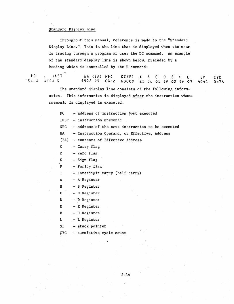
Standard Display Line
Throughout this manual, reference is made to the "Standard
Display Line." This is the line that is displayed when the user
is tracing through a program or uses the DC command. An example
of the standard display line is shown below, preceded by a
heading which is controlled by the H command:
i~ST EA ( t A) f\fC CZSfl A B C 0 E ... L ~ TA ~ 0 5102 ~ ~ ,,., 00t.;2 GOOOC 2~ 5c. O~ 5~ 02 5f- 07
The standard display line consists of the following inform-
ation. This information is displayed after the instruction whose
mnemonic is displayed is executed.
PC - address of instruction ju·st executed
INST - instruction mnemonic
NPC - address of the next instruction to be executed
EA - Instruction Operand, or Effective, Address
(EA) - contents of Effective Address
C - Carry flag
Z - Zero flag
S - Sign flag
P - Parity flag
I - Interdigit carry (half carry)
A - A Register
B - B Register
C - C Register
D - D Register
E - E Register
H - H Register
L - L Register
SP - stack pointer
~YC - cumulative cycle count
2-14
SP eye 4041 O~76

The following line shows the short format of the standard
display line. This form of the standard display line is listed
when the "FORM SIt command is specified. The line consists of the
Program Counter, the Instruction Mnemonic, and Register A.
0000 MVI A,Ol 01
2-15

Character Set
The following list describes the characters that the simulator
will recognize. Use of any other characters'will cause the simulator
to generate errors. Most of the special characters have no particular
meaning in the simulator and may only appear within quote marks to
denote an ASCII character.
Alphabetic Characters
ABCDEFGHIJKLMNOPQRSTUVWXYZ
Numeric Characters
o 1 2 345 6 7 8 9
Special Characters
~ Blank Character ) Right Parenthesis
> Greater Than Period
< Less Than & Ampersand
Single Quote " Double Quote
Commd II Sharp
+ Plus % Percent
- Minus Colon
/ Slash Semi-colon
$ Dollar Sign = Equal
* Asterisk ? Question Mcirk
( Left Parenthesis @ At Sign
Exclamation Tab

Constants
A constant is an invariant quantity which may be an arithmetic
value or an ASCII charact~r code. There are several ways of spec
ifying constants in the simulator.
Decimat constants can be defined as a sequence of numeric
characters optionally preceded by a plus or a minus sign. If
unsigned, the value is assumed to be positive. Other constants
are defined by placing a one letter descriptor after the constant.
If the descriptor is hexadecimal, a leading 0 must be added to
values that start with A-F (unless the user has specified the
"BASE RS" command). This will distinguish a hexadecimal number
from a symbol. The legal descriptors and their corresponding
bases are shown below. If no descript~,r ,i~.giv.en,-the "number.: is
assumed to be decimal . . ; .", __ ·-~"''''''·--''·-·-·--''~r'''''_''''~''
B - Binary
a - Octal
Q - Octal
D - Decimal
H - Hexadecimal
An ASCII character constant may be specified by enclosing a
character in single quotes. (For example, 'A"'.) The character
constant may be used anywhere that a numeric constant may be used.
Through use of the BASE command, the user may specify that all
numeric constants are in hexadecimal. This is useful for those
who debug their programs in hexadecimal, since it makes it unneces
sary to specify the "R" after each constant. (See BASE command for
further details.)
2-17

Symbols
A symbol is a sequence of characters, the first of which must
be alphabetic or one of the special characters ? or @. Except for
these two special characters, only alphanumeric characters may be
used in a symbol.
Only the first six characters of a symbol define the symbol and
are retained by the Simulator in the symbol table. Additional
characters may be added to a symbol for documentation. The parameter
in the program that dictates the length of a symbol may be changed
by the user at compile time (see Installation Notes).
Typically, a user will use those symbols that were defined
during the assembly of the program being simulated and that were
read into the Simulator along with the object data. However, a
user may define new symbols or change the value of a symbol with the
SSYM command.
Since some assemblers and higher level languages allow the
definition of the same symbol more than ·once in a program (in
macros, for example), a method is required to uniquely specify such
a redundant symbol to the Simulation program.
The Simulator enables the user to uniquely specify a
redundant symbol by allowing the specification of a "symbol string"
in place of a symbol. For example, assume that the label "CALR" is
a val id, though redundant, symbol, an.d the user wishes to refer
to a particular occurence of that symbol in the program. This may
be done by specifying a unique symbol string in a command argument
consisting of one or more symbols whieh preceed the symbol of
interest in the symbol table.
In the example just mentioned, assume that the symbol "LOOP2"
preceeds the symbol "CALR" in the symbol table at the occurrence
the user wishes to refer to. Then specifying "LOOP2/CALR" will
2-18
uniquely specify the occurence of the symbol "CALR" desired. Slash
characters are used to separate, concatonate, symbols in a symbol
string. Such a concatenated symbol string may be used anywhere a
simple symbol is permitted. A symbol string of the form "CALR/CALR"
is permitted and would indicate the second occurrence of the symbol
"CALR". The DSYM command may be used to display the symbol table and
determine the sequence of symbols in the table. Typically, dupli
cate symbols will not be present, and a single symbol will be
sufficient to uniquely define that symbol.
The general format of the symbol string is:
This causes a search for sym! followed by a search for sym2and
so on until sym is found. A symbol string can be used in any n
expression that a single symbol may be used since it evaluates to a
single symbol value. A constant may be added or subtracted from the
final symbol in the concatedated string as if the string were a
solitary symbol.
2-19

Program Counter
By use of the symbol U$", the user may include the current value
of the simulated program counter in any expression. "$" always
represents the address of the next instruction to be executed or
the new value of the program counter if it has been modified by the
SET command. For example, the following commands are valid:
SET PC=$+20
RA $+2 10
Expressions
An expression is a sequence of one or more symbols, constants, or
the location counter symbol, "$", joined by the arithmetic operators
+ and -. Parenthesis are not allowed and all expressions are evaluated
from left to right •.
Expressions may be used anywhere a numeric value is required.
All arithmetic is performed using 16 bit values and hence all values
are modulo 65536.
2-20

Range Lists
Many of the simulator commands accept operands that may
consist of a single value ~ a contiguous range of values. This
is called a Range List. Typically, a Range List specifies a range
of addresses for a command. For example, to display a group of
memory addresses, the user may type:
DM 0 0FFH
',The address range specified is a Range List. In general, a Range
List consists of a single expression or two expressions without
a separating connna. Thus the above command will display all
memory locations from 0 to 0FFH , while the command
DM 0, 0FFH
would display only locations 0 and 0FFH. From the above examples
it can be seen that a separating comma determines whether a range
list consists of a single value or a range of values. It should
be noted that the comma must immediately follow the first value
but blanks may exist between the comma and successive values.
In a range list, the second expression, if present, must be a value
greater then or equal to the first expression, otherwise an error
message will be generated.
Remember, commas separate ranges and blanks separate values
within a range.
2-21

SIMMULATOR COMMANDS
This section describes the simulator commands. A command begins
in the first column of the input line. Only one command may be
placed on a line; however, many commands allow multiple arguments.
At least one blank or tab must separate the command from any operands.
In general, command operands may be separated by blanks, tabs, or
commas. For some commands a blank or tab as the separator will per
form a different function than a comma. Remember that range lists are
separated by a blank or a tab. Individual addresses are separated
by commas. Multiple command arguments are separated by commas.
The following nomenclature is used in the command descriptions:
{ } - denotes an optional operand or part of the command name
R - indicates a Range List
A - denotes a memory address
N - denotes an expression
V - denotes an expression and typically represents a
byte value
3-1
* ~ Comment Line 1.
A comment may be included among Simulator Commands by placing
an "*" or ";" as the first character on a command line. In some
cases a comment may be included on the same line as a command but
only if the command requires a definite number of parameters and
they have all been specified.
Comments are useful to document and describe blocks of commands
or data values that seldom change.
Example:
* THIS SIMULATION TESTS THE BINARY TO BCD CONVERSION
PROGRAM. FOR THE Z80 MICROPROCESSOR
3-2

BASE - Set Numeric Input Base
BASE {D,H,HS}
All numeric values specified as input data or command arguments
are assumed to be decimal unless a descriptor is used to indicate a
different base. The user may specify hexadecimal, decimal, octal, or
binary be placing the descriptors H, D, 0 or Q, or B after the value.
For example: 37Q.
The BASE command may be used to specify that all numeric values
will be treated as hexadecimal values. There are two hexadecimal modes
that can be specified. The "H" operand specifies that all input values
will be treated as hexadecimal; values that start With A-F must
begin with a zero in this mode. The "HS" operand specifies that all
input values will be hexadecimal and, in addition, the values do not
have to start with a leading zero. In this case, input data values
beginning with A-F are first assumed to be symbols. If no corres
ponding symbol is in the symbol table, the input data is assumed to be a
numeric. If the base is set to either the "H" or "HS" mode, the
descriptor H after a numeric data value is optional. Thus lFH could
also· be specified as IF.
The "D" connnand argument may be used to switch back to the
decimal default mode.
Note, when in one of the hexadecimal modes, values other than
hexadecimal may not be entered by appending a descriptor after
the value. Except for the descriptor ,"H", any other descriptor
will either cause an error to be generated or cause the input data to be
recognized as a value not intended by the user.
Example:
BASE D BASE HS
Error Conditions:
1. . Operand specified and not D, H, or HS
3-3

BP - Set Breakpoint NBP - Clear Breakpoint
{N}BP
The BP and NBP are used to set or clear an instruction or operand
breakpoint. During execution of instructions by the E, EA, or TB
commands, the encountering of a breakpoint will cause program execution
to terminate. '!be standard display line is then displayed. Break
p.oints may be set for any memory location. The memory location may
contain an instruction, an instruction operand, or may even b~ an
I/O location.
The BP command is used to set a breakpoint at an address or a
range of addresses. The NBP command enables the user to negate the
effect of the BP command. Any addresses specified in the NBP co~nd
will have their breakpo'int flags permanently cleared so that no break
point will occur when these addresses are accessed.
These commands may also be specified without any operands. In this case, the command affects only the master breakpoint flag. When
the NBP command is used without any operands, all checks for breakpoints
are inhibited during the E, EA, or TB commands, but the breakpoint
flags previously set will remain set. "The BP command with no operands
may then be used to reactivate the breakpoints. This feature is useful
When the user thinks a section of code is completely debugged and ready \ "
for final checkout, but is not completely sure the code is valid for all
possible inputs. The user may turn off breakpoints, run several test
cases, and, if a problem is encountered, turn the master breakpoint
. flag back on for further debugging.
Example:
NBP BP NBP
77H, l00H l0FH,5 lBH
Error Conditions:
1. Invalid operand
2. Ending address less than starting address in range list
3-4

DATA }IDAT SDAT
DATA DATA SDAT
Specify Input Buffer Data
{*} N {V, V, ••• }
{V, V, ••• }
The DATA, MDAT, and SDAT commands are used to enter data into
the Simulator's input data buffer. This FIFO buffer may be used
to supply data values as required to any of the input ports. The
DATA directive specifies values for normal ports, the MDAT directive
specifies values for memory mapped I/O ports, and the SDAT directive
specifies values for the serial port. A port can be made to read data
from the Data Buffer through the use of the IB, MIB, and SIB
commands. The DATA, MDAT, and the SDAT commands may also be used
to vary the parameters associated with the input data buffer. The
commands may be used in the ways described below to p.erform the
stated functions. The port number parameter, N, is not specified
for the SDAT command.
1 •. If no argument is specified, the input data buffer table
is cleared of data for all ports. This variation of the
command is typically used when the user wishes to change
the data in·the buffer. The user would specify the command
without any operand followed by the command with operands.
The second command would be'used to fill the buffer with
i data. Any· of the three commands may be used to clear the
buffer for all types of ports.
2. If an "*" is specified as the operand, then any port
requesting data will obtain the first data value associated
with the port. In this case, the "pointers" associated
with each port are. reset to po.int to the first data value
entered.
3. "DATA N" acts in a similar manner to "DATA *" except
only the "pointer" for port N is reset. This form does
not apply for the SDAT command •.
3-5

4. "DATA N V •.• " is used to enter data values for port N
into the buffer. The order in which· the data is entered
is the same order in which the data will be "read" by
microprocessor input instructions. Therefore, the buffer
is refered to as a FIFO (first-in-first-out) buffer.
Input data values for different ports may be entered into the
buffer in any order; all data for a particular port does not have to
be entered consecutively. The user may enter 5 bytes for port 0 fol
lowed by 3 bytes for port 2 followed by another 2 bytes for port 0. Only the data associated with a particular port can be "read" by
that port.
If the program "reads" more data values from a port than have
been entered into the buffer, the data values. specified will be used
again, starting with the first data value entered for that port. In
other words, the data "pointers" are automatically reset when
necessary. This feature can be advantageous when an input port
supplies the same data values repeatedly.
If the program being simulated attempts to read input data from
the buffer and no data has been entered for that port, a warning
will be printed. The contents of the registers will not change.
No data values will be entered into the buffer unless the input
line is error free. This avoids the problem of the user knowing if
any of the input data values were entered when an input error occurs.
Example:
DATA DATA DATA DATA MDAT SDAT
* 1 45,6FH,0, ° 7 1000H 25,10 10011
Error Conditions:
1. Port number greater than 255, 65535 for memory ports
2. Data value greater than 255, 1 for serial port
3. Invalid operand
4. Data buffer filled
3-6

DC ~isp1ay f?U
DC {*}
This command is used to display the standard display line
immediately. The long form of the display line is used even if the
command "FORM SIt has been specified. This command is typically used
after instruction execution with the short display line ~r if the user
is using a terminal and the listing is routed to another device, making
the results of the last instruction execution unavailable.
The line displayed by the DC command will always contain the
address and instruction mnemonic of the last instruction executed.
If the user has modified the program counter, execution will commence
at the new address displayed in the NPC field. Any modifications to
the other elements of the display line (PSW, registers, etc.) will be
immediately reflected by the command.
The registers displayed by this command.wi11 be from the
currently selected register. bank. The user may examine the alternate
register bank "!alues by specifying "*" as the command operand.
The DC command does not modify any of the heading parameters
or counts. A heading is never displayed with this command.
Example:
DC DC *
Error Conditions:
1. Invalid operand
3-7
DEL - Delete Symbols
DEL {symbol string{,symbol string, ••• }}
The DEL command is used to delete a few symbols from the
symbol table or to delete all symbols from the symbol table. If
no operand is specified, then all symbols in the table are deleted.
If a symbol(s) is specified, only that symbol(s) is deleted from
the symbol table.
A deleted symbol will provide additional room in the symbol
table, .which may be of advantage if the user has encountered the
"SYMBOL TABLE FULL" message.
Example:
DEL DEL TABLE, LABEL/ONE
Error Conditions:
1. Invalirl symbol string
3-8

DR'- Qisplay ~istory
DR {V}
The DR command may be used to display the addresses of previous
instructions executed by the simulator. "V" instruction addresses
will be displayed. Each line of the display consists of the address
of the instruction executed, starting' with the instruction executed
"V" instructions ago.
If no operand is specified, 32 in~truction addresses will be
displayed. If the operand is greater than 32, only 32 instruction
addresses will be displayed. An example of the DR command may
be found in the sample simulations.
At the start of simulation, if "V" is 'greater than the number
of instructions executed, "****" will be displayed for instruction
addresses not execut~d.
Example:
DR 7
3-9

DIN Qisplay ~ut Port DOUT Qisplay Output Port
DIN R { ,R, R, ••• } DOUT R { , R, R, ••• }
The DIN and DOUT commands are used to display the contents
of the processor input and output ports. The last value read from
an input port is always saved in the input port latch and may be
examined by this command. The DIN command also allows the user to
examine the value to which an input port has been preset by the
SIN or FIN command.
The last value written to an output port is saved in the
output port latch and may be examined by the DOUT command. This
command also allows the user to display the value to which an
output port has been set by the"SOUT command.
The maximum value of any operand is 255.
Example:
DIN O,1 DOUT 0 16
Error Conditions:
1. Operand not specified
2. Port number out of range
3. Invalid operand
3-10

DM - Qisplay ~emory D
D{M} R {,R, R, ... }
This command is used to display the contents of the simulated
memory. The operands are ranges of addresses which are to be .
displayed. Each range will be displayed starting on a new line. Up
to 16 bytes will be displayed on each line. An example of the DM
command may be seen in the sample programs.
The maximum value of any operand may be 0FFFFH or the maximum
memory size set at compile time if smaller.
This command may also be used to examine memory mapped. input
port preset values or the last value read at a memory mapped port
that is not preset. Likewise, the command can be used to examine
the last value to be written to a memory mapped output port.
Example:
DM 0 3FH t 100H, 200H DM 300 3FF
Error Conditions:
1. Operand not specified
2. Address out of range
3. Invalid operand
4. Ending address of range less than starting address
3-11

DIM Display Interrupt Mask
DIM
This command is used to display the Interrupt Status and serial
input bits, 1M, read by the RIM instruction; the serial output
bit, SOD; and the edge triggered Restart 7.5 flipflop.
The output generated by this command is shown below.
1M = 10000000 S00 = 1 liTJ.5 = 0
The Binary bits shown in the interrupt mask correspond exactly
to those read into the A register by the RIM instruction. The
bits are:
Bit 7 - Serial input data
Bit 6 - Interrupt Pending, Restart 7.5
Bit 5 - Interrupt Pending, Restart 6.5
Bit 4 - Interrupt Pending, Restart 5.5
Bit 3 - Interrupt Enable Flag
Bit 2 - Interrupt Mask Bit, Restart 7.5
Bit 1 - Interrupt Mask Bit, Restart 6.5
Bit o - Interrupt Mask Bit, Restart 5.5
3-12
DSYM - Qisplay ~bols
DSYM {symbol string {,symbol string, ••• }}
This command is used to display the value of a symbol or the
values of all the symbols in the symbol table. If no operand is
specified, then each symbol in the symbol table along with its
value is displayed, one symbol per line. If operands. are specified,
each symbol specified along with its value is displayed.
If there are no symbols in the symbol table, the command
wi th no operand will display no info.rmation. If a symbol is
specified but it is not in the symbol table, the message
"UNDEFINED SYMBOL" will be displayed.
Example:
DSYM DSYM DSYM
START , TABLE GO/DATA
Error Conditions:
1. Undefined symbol present in argument list
2. Invalid symbol terminator
3-13

E - Execute Instructions EA - Execute Instructions until Address
E {N} EA A {N}
. The E and EA commands cause the program to begin execution of
instructions. The execution begins at the address contained in
the simulated Program Counter. The standard display line is not
displayed for instructions executed unless the trace· flag for that
instruction has been set by the TR command. This distinguishes
these commands from the T and TA commands.
These commands will terminate program execution and display the
standard display line for the final instruction executed if anyone
of the following conditions is met:
1. A breakpoint is encountered
2. An illegal instruction is executed
3. The number of instructions specified by the LI command is
executed.
For the E command, the optional "N" parameter specifies the num
ber of instructions that should be executed before the command termin
ates. This value overrides the value specified by the LI command.
The EA command is similar to the E command except that the pro
gram will continue to execute instructions until the instruction at
address "A" is executed. If "N" is also spec,ified, the instruction
at address "A" must be executed "N" times before the command ter
minates. In either case, the EA command will also terminate program
execution if anyone of the three conditions" mentioned above is met.
Example:
E EA
20 3FH 4
Error Conditions:
1. Address not specified for EA command
2. Invalid operand specified
.3-14

FIN Iill '!!!put Port FOUT Fill Output Port
FIN A A V { ,A A V, ... } s e s e FOUT A A V { ,A A V .' .. } s e s e
The FIN and FOUT commands are used to fill a group of input or
output ports will a specified value. "As" specifies a start,ing
port number and "A " specifies the ending port number that will be e filled with the value "V". All ports ,starting at "As" up to and
including "A " will be set to the value "V". As many port ranges e as desired may be set to the specified values with a single command.
The maximum value that may be specified for a port number is
255. The maximum value of the data that can be placed in a port
buffer is 0FFH.
The FIN command may be used to specify the Preset value used
when an input port is specified as preset with the IP command.
Although no microprocessor instruction can read the values set
into an output port latch, the user may wish to initialize these
values with the FOUT command before executing a section of code that
writes data to these ports.
Example:
FIN 0 7 .FOUT 4 7
Error Conditions:
0FFH 3, 0 2 4FH
1. Port number too large
2. Ending port number less than starting port number
3. Port value too large
4. Operand error
3-15

FORM - Set Display Line Format
FORM {L}{S}
The standard display line consists of the Program Counter,
instruction mnemonic, Next Program Counter, status bits, registers,
and the cumulative cycle count. For users in an interactive mode
and with slow terminals, the listing of a standard display line
requires a reasonable amount of time and contains more information
than is needed. These users may use the FORM command to turn on
the short display line listing option. The short standard display
line consists of the Program Counter, instruction mnemonic, and the
A register. Whenever a standard display line is required, only
this information i$ displayed. The one exception to this is the
DC command, which always displays the long form of the standard
display line.
When it is necessary only to follow the flow of the program
and the values of the registers are not of interest, the short
display line format is particularly useful.
Users may modify the information that is displayed with the
short display line option to suit their particular needs. How to
modify the contents of this line is discussed in the Simulator
Installation Notes.
The "L" operand requests the long display format while the
"S" operand requests the short format. The default is the long
format.
Example:
FORM S FORM L
Error Conditions:
1. Operand not specified
2. Operand not L or S
3-16

FM - Fill Memory
FM A e v {,A s A e
V, ••• }
The FM command is used to fill a range of memory loca-
tions with a specified value. "A" specifies the starting memory s
address and "A " specifies the ending memory address that will be e
filled with the value "V". All memory locations starting at "A " s up to and including "A " will be set to the value "V". As many e blocks of memory as desired may be set to a given value with a
single command. This command is useful when the user desires to
read a new object module into simulated memory after already having
done some simulation with a different object module. In this case,
the user could fill the complete Memory with the halt opcode value.
The simulator "initially sets the Memory to this value so that, if
the program counter gets out of range, the program will halt.
The maximum value that may be specified for any memory addresses
is 0FFFFH or the maximum memory size set at compile time, if tha"t
is smaller (see Installation Notes).
Example:
FP 0 OFFFFH 76H
Error Conditions:
1. Memory Address too large
2. Ending address less than starting address
3. Memory value too large
4. Operand error
3-17

H - Specify heading count
H {N}
This 'command is used to specify the heading display count.
The heading, which can be seen in· the sample program, describes
the information on the standard display line.
If no operand is specified on the command, then no headings
will be displayed during further instruction execution and listing.
If the heading count is specified as 0, then a heading is generated
immediately but no other parameters set by previ'ous H commands are
affected. "H- 0-" is typically used when the user has turned the
heading off, but when the user would like a single heading before
generating tra.ce information.
If the heading count is greater than 0, a heading will be displayed
after every Nth instruction has been traced. The default is "H 10".
Example:
H H 25
Errors:
1. Invalid operand specified
3-18

IB Read Port Input 'Data from Data Buffer IC Read Port Input Data from Current input device IP Read Port Input Data from preset data latch IS Read Port Input Data from Standard input device
Ix R {, R, R, ... }
These four commands allow the user wide flexibility in the
simulation of microprocessor input instructions. Each port may
"read"'its data from one of the sources described below. Of course,
the source of a port's input data can be altered at any time during
the simulation.
IB - any port specified by this command will "read" data from
the input buffer table (see DATA command). If more data is
"read" than has been entered in the table, the data is re-read.
An attempt to read from the buffer, by a port for which no
data has been entered, will result in a warning message. In
the batch mode, the input instructions will be executed but
the accumulator will not change. If in the interactive mode,
the Simulator will return to the command mode.
IC - a port specified in this command will "read" data from
the current input device. This device may be either the
standard input device or a device or file specified by the R
or RE commands. If the current device is the same as the
standard device, this command has the same effect as the IS
command.
\
IS - a port specified in this command will "read" data from the
standard input device that was set at compile time. If the
program is in the interactive mode, the following message will
be displayed to request the input value from the user:
*PPPP INPUT ON PORT N =
where PPPP is the address of the input instruction and N is
3-19

. "
the por~ number. If the program is in the batch mode, no
message w:t1l be displayed. In the batch mode, data 'bytes must
be included in the command stream where required.
IP - a port specified in this command will "read" data from
the preset data latch. The value in this latch may be specified
by the SIN command. This input mode is typically used for those
, p'orts which contain data which will not change during the
simulation, such as an I/O status value.
When the Simulator is first entered, all ports are initialized
as though they were set by the Ie command. When reading data in
the batch mode or in a read mode, from a port set by the Ie command
(also by IS in batch mode), the user must provide the data values in
·the command stream where. needed. For example, if a T or E instruction \
. causes five 'input values to be read, these five values must follow
the T or E command. The user may specify more than one data byte
per line. The data bytes are separated by blanks.
If an End-of-fi1e (EOF) condition is encountered while reading
input data for ports in the Ie or IS mode, the Simulator will
return to the command mode. This is especially useful in the
interactive mode as a way to stop program simulation. If invalid
data is read by the Simulator or a value is out ~f range, the
response will depend upon the mode of the Simulator. If the user
was prompted by the message requesting input data as shown und~r
the IS command description, the user will be prompted again for the
correct data. If the user was in' any other mode, an error message
will be displ,syed and the Simulator will return to the command mode.
Arl error does not caus,e the program counter to be updated. This
'allows the user to ~asi~ycontinue processing at the same input
instruction.
3-20,

Example:
IB 2
IS 0 2,7
Error Conditions:
1. Input port greater than 255
2. No operand specified
3-21

INT - Set Interrupt NINT - Clear Interrupt
INT NINT
type cycles {instruction or address}
These commands may be used to simulate the interrupt mechanism
of the microprocessor. Normal 8080, Restart, or Trap interrupts
can be simulated. Only one interrupt may be pending at any time.
If the INT command is used to specify an interrupt, any previously
specified interrupt that has not occurred is cancelled. For a
Normal 8080 or Restart interrupt to be recognized, the interrupt
enable bit must be set. For a Restart interrupt to be recognized,
the interrupt must not be masked. If these bits are not set, the
interrupt will not be recognized at the specified time. However,
the interrupt will still be pending and, unless cleared, will
occur as soon as the interrupt enable bit is set.
"Type" specifies which kind of interrupt is to occur:
I Normal 8080 Interrupt
T Trap Interrupt
5 Restart 5.5 Interrupt
6 Restart 6.5 Interrupt
7 Restart 7.5 Interrupt
"Cycles" specifies the number of cycles after the current
instruction at which the interrupt is to occur. A cycle count of
o will cause an interrupt to occur immediately, as if the interrupt
had actually occured during the previous instruction execution.
Remember, if an interrupt occurs during the execution of an in
struction, that instruction execution·is completed before the
interrupt is recognized.
For a Normal 8080 interrupt, the user may specify any 8080/8085
instruction with the interrupt command. The bytes of multi-byte
3-22
instructions are separated by blanks. The instruction field is
ignored for Restart and Trap interrupts.
If no instruction or data byte is specified, the last one
specified is used.
As with the actual 8080/8085, the interrupt enable bit is
reset when the Simulator is reset and when the simulation program
is first executed.
Although the interrupt simulation mechanism is based on a
cycle count, it is also easy to simulate an interrupt at a parti
cular address. The user may set a breakpoint at the address he
wishes to simulate the interrupt and when that address is reached,
he can specify an interrupt command with a cycle count of O.
Examples (Mode 0 assumed):
INT I 25 C7
INT 6 o
NINT
Error Conditions:
1. Invalid Operand
2. Opera~d Not Specified
Perform Normal 8080 interrupt after 25 cycles, then execute a RST 8 instruction
Perform Restart 6.5 interrupt tmmediately
Clear pending interrupt
3-23

L Load Object Module L8 ~oad Object Module with EYmbol Table
L{S} {*} {I/O device} {file name}.
The L command is used to load an object module into simulated
memory while the LS command is used to load an object module into
simulated memory, and additionally, load any' symbol table information
present in the object module. Note that although symbols may be
present in an object module read by the L command, these symbols will
not be placed into the symbol table. This feature is useful since
the symbols in an object module are placed into the symbol table .
even if the same symbol already exists. Thus the L command avoids
having many duplica~e symbols, reducing the possibility of symbol
table overflow.
The object module may be read into simulated memory from the
logical I/O device number or file name specified in the operand
field. The operands are:
* - the object module is read from the standard object module
unit that was specified in the program at compile time.
This would typically be a paper tape reader or some
default file name. This method avoids the problem of
users having to know the device numbers of peripherals.
I/O device ~ this is a numeric value which specifies that the
object module will be read from the logical unit specified.
file name - specifies that the object module will be read
from the file specified. If the file does not exist,
the message "FILE NOT FOUND" will be printed.
If the user does not specify any .operand, it is the same as if
"*" was specified. After reading the object module, the program will
display the message "NUMBER OF BYTES READ = "If the number of
bytes read is ~, it is possible that the information read was not in
the proper format for an object .module. In this case the message
3-24

"END OF FILE ENCOUNTERED" is displayed. The Simulator's Program
Counter will be set to the starting address specified in the load
module.
Note that in the batch mode, both commands and object module
may be read from the same unit.
Example:
L LS L
* 5 TESTZ8
Error Conditions:
1. Object module contains invalid hexadecimal characters
2. Object module contains invalid symbol information
3. Symbol table overflow. In this case, all remaining symbols
in the object module are ignored and all data is processed
and placed into simulated memory.
4. Checksum error encountered in object module
5. Address out of range. A load address specified in the
object module was larger than the simulated memory.
3-25

LI - Set Instruction Execution Limit
LI N
This command is used to specify a limit to the number of
instructions that will be executed during an E, EA, T, TA, or TB
command. When this limit is reached, the message "LIMIT REACHED"
is displayed and control returns to the command mode. This limit
may be changed for the duration of the command by specifying an
optional limit on the E, T or TB commands. The above message is
only displayed when no limit was specified on the E, T, or TB
command and ,the limit set by this command has been reached. There
is no inherent limit parameter for the EA or TA commands, so the only
limit which applies is set by this command.
This limit applies ,only for the duration of the current command
and is not cumulative for all commands. When running in the batch
mode or a read mode, it may be necessary to increase the limit to
enable a large program to execute to completion with one E or T
command. The default for this command is 1000 instructions.
Example:
LI 100
Error Conditions:
1. No limit specified
2. Error in limit specified
3-26

MIB - Read Memory Mapped input data from Data Buffer
MIC - Read Memory Mapped input data from Current input device
MIP - Read Memory Mapped input data from preset data latch
MIS - Read Memory Mapped input data from Standard input device
MIx R { ,R, R, •.• }
These four commands allow the user wide flexability in the
simulation of Memory Mapped Input. Each Memory Mapped Input Port
may "read" its input data from anyone of the sources described
below. Of course, the source of a port's input data can be altered
·at any time during the simulation.
The memory mapped input commands, MIB, MIC, MIP, and MIS are
analogous to the Normal P9rt Input commands, IB, IC, IP, and IS.
A brief description of the }~emQry Mapped (Input 'Connnarids i:iJs given
here. The user may refer to the Port Input Command descriptions
for more details.
MIB - read memory mapped input data from Data Buffer.
Data is entered into the Data Buffer by the MDAT Command.
MIC - read memory mapped input data from the current input
device.
MIS - read memory mapped input data from the standard input
device. The following message is displayed at the standard
input device in the interactive mode:
*PPPP INPUT ON MEMORY PORT N =
where PPPP is the address of the input instruction and N is
the port number.
MIP - read memory mapped input data from the value preset into
the memory location. The value may be preset by the SM
. command. Note that memory not mentioned by any of the memory
mapped I/O commands acts as though it were preset.
3-27

Simulated memory used as a Memo~y Mapped input port would act
as a preset port if no memory I/O instruction were specified. .There
fore, specifying the MIP command for a memory location not previously
specified as a Memory Mapped input port would have no effect. The
MIP command may also be used to turn a Memory Mapped I/O port back
into regular memory location.
There is no limit to the number of memory locations that can
be declared to be I/O ports.
The actions taken when. an input data error is encountered
are the same ~s those actions taken for normal input port errors.
These error actions are discussed in the Normal Port I/O Command
descriptions (IB, IC, IP, and IS).
Examples:
MIC 5000H,5010H
MIB 5050H
Error Conditions:
1. Port number greater than 65535
2. No operand specified
3-28

MOC Write Memory Mapped Output Data to Current Output Device MOP Write Memory Mapped Output Data to Memory Location MOS Write Memory Mapped Output Data to Standard Output Device
MOx R {,R,R, .•• }
These three commands allow the user wide flexability in the
simulation of Memory Mapped output. Each Memory Mapped output port
may "write" its data to one of the destinations described below.
The destination of a memory mapped port's output data may be changed
at any time during the simulation.
The memory mapped output commands, MOC, MOP, and MOS, are
analogous to the Normal Port Output Commands, OC, OP, and as. A brief description of the Memory Mapped commands is given here.
The user may refer to the Port Output Command descriptions for
more details.
MOC - write output data to the current output device. The
following message is displayed:
*PPPP OUTPUT ON MEMORY PORT N = V
where PPPP is the address of the instruction writing the
vutput data to the port, N is the port number, and V is
the output data value.
MOS - write output data to the standard output device. The
same message described in the MOC command description
is displayed.
MOP - write output data to memory mapped port location only.
Note that memory not mentioned by any of the memory
mapped I/O commands acts as though it is set in this
manner.
Simulated memory used as a memory mapped output port would act
as a latched port (value written to memory location only) if no
~emory I/O instruction were specified. Therefore, specifying the
MOP command for a memory location not previously specified as a
Memory Mapped Output port would have no effect. The MOP command may
be used to turn a Memory Mapped I/O port back into a regular memory
location.
There is no limit to the number of memory locations that can
be declared I/O ports.
Examples:
MaC 500lH,50llH
MaS 50SlH
Error Conditions:
1. Port number greater than 65535
2. No operand specified
3-30

OC Write port output data to Current output device OP Write port output data to data latch OS Write port output data to Standard output device
Ox R {,R, R, .•• }
These commands allow the user wide flexibility in the simulation
of microprocessor output instructions. Each port may "write" its
data to one of the destinations described below. The destination
of a port's output data may be modified at any time during the
simulation.
oc- a port specified in this command will "write" data to the
current output device with the following message:
*PPPP OUTPUT ON PORT N ='V
PPPP specifies the address of the output instruction writing data
to the port, N is the port number, and V is the value written
to the port.
OS - a port specified in this command will "write" data to the
standard output device with the message shown for the OC
command. This command is typically used when the user has
specified the W command but would like to see the output
data cf any output instructions on the standard output device.
OP - a. port specified by this command will "write" data to
the output port latch only. The value in this latch may be
examined by the,DO command. This command is typically used when
output occurs that is not of current interest to the user.
Note that the last value written to a port is saved in the output
port latch regardless of the mode specified for the output port.
At the start of the program all output' ports are initialized as
though they were set by the OC command.
3-31

Example:
OC 0,2 OP 5
Error Conditions:
1. Output port greater than 255
2. No operand specified
3-32

PRO - Protect Memory NPRO
{N}PRO R {, R, R, ••• }
The PRO command allows the user to specify portions of
memory that should not be written into (Simulated ROM). When an
attempt is made to write into Protected Memory, an informative error
message is displayed. The contents of the memory are not changed.
The NPRO command enables the user to negate the effect of the
PRO command. The protect flag will be reset for the address range
specified.
The PRO and NPRO commands may also be specified without any
,arguments. In this case, the commands affect only the master protect
flag. The NPRO command without an argument turns off the master
protect flag. Checking for protected memory will not be performed
until enabled again by specifying the PRO command without any argu
ments. The PRO and NPRO commands do not affect the protect flags
at specific addresses. They only turn the master flag off and on.
Examples:
PRO lOOH 200H'
NPRO a OFFFFH
Error Conditions:
1. Invalid Operand
2. Ending address less than starting address in range list
3-33

R Read Commands RD Read Commands with delay RE Read Commands with echo RED Read Commands with echo and delay
R{D} {*} {I/O device} {file name} RE{D} {*} {I/O device} {file name}
These commands enable the user to read subsequent commands or
input data values from an alternate I/O device. The RE and RED
commands will read the input data from the alternate device or disk
file and also echo the input to the current output device. The
RD and RED commands,will not go into effect until one additional
command has been entered on the current device. These commands
may be used when reading input data from a file. The RD or RED
command can be specified immediately followed by a trace or execute
command. If there was not a one~instruction delay before the input
device was switched, the first entry in the file of input data would
have to be a Trace or Execute command. 'The Rand RE commands are
typically used to execute a complete set of commands that have
been debugged and reside on a file.
Subsequent input may be read from the following sources when
the argument underlined is specified:
* - read subsequent input from the standard input device
specified in the program at compile time. This is typically
a terminal in the interactive mode or a card reader in the
batch mode. The command with this parameter is not usually
used since all input is typically read from the standard input
device, anyway. However, it may be used to echo commands to
the terminal in the interactive mode or to not echo commands
to the list device in the batch mode. In addition, in the
interactive mode, using this command will cause the command
prompt character not to be displayed.
I/O device - this is a numeric value that specifies a FORTRAN
logical I/O unit from which subsequent input will be read.
3-34

file name - specifies that subsequent input will be read from
the file specified. File names must begin with an alphabetic
character. If the file does not exist, the message "FILE
NOT FOUND" will be displayed.
If the user does not specify any operand, it is the same as
if "*" were specified.
Ex~mple:
RE RD R
* TESTFILE 5
Error Conditions:
1. File not found
2. Invalid I/O device number specified
3-35

RES Reset Microprocessor
RES
The RES command is used to reset the Simulator in a similar
fashion to activating the reset line on the actual device. The
RES command performs the following functions:
1. Program coun,ter is set to 0000 2. Stack Pointer is set to 0 3. Interrupt enable bit is reset
4. All restart interrupts are masked
5. All accessable Registers are set to 0 6. Cycle count is set to 0
After a RES command, if the user enters a DC command, the
resulting output display will still show the address of the last
instruction that was executed. However, the Next Program Counter
(NPC) will contain a zero. The elements listed above will be set
to the values specified above. The next instruction executed will
be the one at location 0.
3-36

RET - Return from Read MOde
RET
This command is used to restore the simulator input mode to the
standard input device after an R, RD, RE, or RED command (Read Commands
.from file) has been specified. Thus the RET command should be the last
command in a command stream read by one of the above commands. An
End-of-File condition will have the same effect as the RET command.
If this command is used when a read command is not in effect, no
action takes place.
The RET command is similar to the "R *" command. The "R *" command returns control to the standard input device as does the
RET command. . However, as will all R commands, th'e "R *" command
prevents the prompt 'character from being generated in the interactive
mode. In contrast, the RET command exits the read mode and displays
the prompt character in the command mode.
3-37

S Set Processor Element SET
S {ET} ele=V {,ele=V,ele=V, ••• }
The SET command is sued to set the values of the various
registers and status bits of the microprocessor.
The elements, along with the legal maximum values, are listed
below:
A - Register A (255)
B - Register B (255)
C - Register C (255)
D - Register D (255)
E - Register E (255)
H - Register H (255)
L - Register L (255)
Z - Zero Flag (1)
CY - Carry Flag (1)
P - Parity/overflow Flag (1)
S Sign Flag (1)
I Interdigit Carry, Half Carry (1)
SP - Stack Pointer (655,35)
CC Cycle Count (65535)
PC - Program Counter (65535)
IE - Interrupt Enable (1)
1M - Interrupt Mask (7)
17 - Restart 7 Flip Flop (1)
SI Serial Input Latch (1)
So - Serial Output Latch (1)
Most of these elements can be displayed through use of the
DC and DIM commands.
3-38

The equal sign between the elements and their values is
optional. If desired, it can be replaced with a blank.
Examples:
SET A=45H, C=55, PC=200H .
SET IE=l
Error Conditions:
1. Invalid elements specified
2. Invalid separator after element
3. Element value out of range
3-39

SIN - ~et ~ut Port SOUT - !et Output Port
SIN A SOUT A
V {,V, V, ••• } V {,V, V, ••• }
'The SIN and SOUT commands are used to set and/or examine the
value of the processor input and output ports respectively. The first
operand of these commands specifies a port number at which the
following data will be entered or examined. The first data byte (V)
will be entered at the specified port number and successive data bytes
will be entered at successive ports.
The user may continue this command on additional lines by
terminating the last data value on a line with a comma. If the
command is continued, the address of the next I/O port, followed
by the contents of that port, will be displayed on the following
line. For example:
0001 05-
The user may then modify the contents of this port as well as the
contents of successive ports as required, starting at the port
number displayed. If a comma is the first character on the line,
the contents of the port· at the address shown will not be modified
and the display will advance to the next port .. This feature may be
used to examine and modify ports one at a time, skipping over ports
that the user does not wish to change. If the last data value on a
line is not terminated by a comma, the command terminates.
The maximum value that may be specified for the starting port
number is 255. If, dur'ing the entry of data into the I/O ports,
the maximum port number is exceeded, the command will terminate with
the message "ADDRESS OUT OF RANGE". All data entered up to this
point will have been placed into the port latches. The maximum
value that may be specified for a data value is 0FFH •
. 3-40

These commands enable the user to specify the preset value to
be used with a port when the port is declared preset with the IP
or OP commands. Keep in mind that if an input port is preset (IP
command), its value will not change except by use of the SIN or FIN
command. However, any output instruction will change the value
placed into an output port by the SOUT command.
Example:
SIN
SOUT
o 1
4 0FH,2
Error Conditions:
1. No starting port number specified for command
2. Data value greater than 255
3. Port number assumes value greater than 255 during command
4. Invalid operand
3-41

~ Read Serial Input Data from Data Buffer SIC Read Serial Input Data from Current Input Device SIP Read Serial Input Data from Preset SIn Latch SIS Read Serial Input Data from Standard Input Device
SIx
These four commands allow the user wide flexability in the
simulation of Serial Input. The Serial Input Port may "read"
its input data from anyone of the sources described below. Of
course, the source of a port's input data can be altered at any
time during the simulation.
The Serial input commands, SIB, SIC, SIP, and SIS, are
analogous to the Normal Port Input commands, IB, IC, IP, and IS.
A brief description of the Serial Input Commands is given here.
The user may refer to the Port Input Command descriptions for
more details.
SIB - read serial input data from Data Buffer. Data is
entered into the Data Buffer by the SDAT Command.
SIC - read serial input data from the current input device.
SIS - read serial input data from the standard input device.
The following message is displayed at the standard
input device in the interactive mode:
*PPPP INPUT ON SERIAL PORT =
where PPPP is the address of the input instruction.
SIP - read serial input data from the value preset into the
SID latch. The value may be preset by the SET command.
Serial input is initially set to this mode.
Every time a RIM instruction is executed, an input data value
is supplied. If the user is not interest'ed in simulating serial',
I/O, he should leave the mode set to preset input, the default.
When a RIM instruction is executed, no message will be issued asking
for input data, and the user can ignore the SID bit.
3-42

The actions taken when an input data error is encountered
are the same as those actions taken for normal input port errors.
These error actions are discussed in the Normal Port I/O Command
descriptions (IB, IC, IP, and IS).
Examples:
SIC
SIB
3-43

SM §.e t ~emory
SM A V {, V, V, ...}
This command is used to enter and/or examine data in the
simulated Memory. The first operand of this command specifies
a Memory address at which the following data will be entered.
The first data byte (V) will be entered at the starting address,
"A", and successive data bytes will be entered at successive
addresses.
The user may continue this command on additional lines by
terminating the last data on a line with a comma. If the command
is continued, the following line will display the address of the
next memory location followed by the contents of that location.
For example:
03A2 67-
The user may then modify the contents of this location as well as
enter as many data values as required starting at the address
shown. If a comma is the first character on the line, the contents
of memory at the address shown will not be modified and the display
will advance to the next address. If the last data value on a
line is not terminated by a comma, the command terminates.
The. maximum value that may be specified for the starting address
is 0FFFFH or the maximum memory size set at compile time if smaller.
If, during the entry of data into the memory, the maximum memory
size is exceeded, the command will terminate with the message
"ADDRESS OUT OF RANGE". All data entered up to this point will
have been placed into the memory. The maximum value that may be
'specified for a data byte is 0FFH.
Example: (simulator output is underlined)
8M 200H 5, 3,0B5H SM 0 1, 0001 09 - , 0002 45 - 45,46
3-44

Error Conditions:
1. Starting address not specified
2. Data value greater than 255
3. Address assumes value larger than 0FFFFH during command
4. Invalid operand
3-45

SOC Write Serial Output Data to Current Output Device SOP Write Serial Output Data to SOD Latch SOS Write Serial Output Data to Standard Output Device
SOx
These three commands allow the user wide flexability in the
simulation of serial output. The Serial output port may "write"
its data to one of the destinations described below. The destin
ation of a serial port's output data may be changed at any time
during the simulation.
The serial output commands, SOC, SOP, and SOS, are analogous
to the Normal Port Output Commands, OC, OP, and as. A brief
description of the serial commands is given here. The user may
refer to the Port Output Command descriptions for more details.
SOC - write output data to the current output device. The
following message is displayed:
*pppp OUTPUT ON SERIAL PORT = V
where PPPP is the address of the instruction writing the
output data to the port and V is the output data valu~.
SOS - write output data to the standard output device. The
same message described in the SOC command description
is displayed.
SOP - write output data to SOD latch only. Serial output
is initially set to this mode.
Every time a SIM instruction is executed, an output data
value is written to the specified device. If the user is not
interested in" simulating serial I/O, he should leave the mode set
to latched output only, the default. No messages will be issued.
When a SIM instruction is executed, no message will be issued
specifying the output data and the user can ignore the SOD latch.
Example:
Soc SOP
3-46

SSYM - ,§,et ~bols
SSYM symbol string=V {,symbol string=V, ••• }
The command is used to change the value of a symbol already
in the symbol table or to enter a new symbol and its value into the
symbol table. If a symbol specified by this command is already
in the table, its value will be set to that specified by this
command.' If the symbol is not already in the symbol table, it
will be placed into the symbol table.
The symbol strings used in this command may not have a value
placed after the last symbol, e.g. AB/CD+-S. "V" may be any valid
expression and may itself contain symbols. This includes the symbol
actually being defined by this command if it already exists in
the symbol table. The equal sign between the symbol and the value
is optional and may be replaced by a blank.
Example:
SSYM ' START=S SSYM DATA/ENTRYl=3,TABLE=lFH
Error Conditions:
1. Symbol table is full
2. Invalid symbol string format
3. Operand error
3-47

T - Trace Instructions TA - Trace Instructions until Address TB - Trace .Instruc tions with !reakpoints
T {N} TA A {N} TB {N}
These commands cause the program to begin execution of instructions.
The standard display line is displayed after each instruction has been
executed.
The optional "N" parameter on the T and TB commands specifies ·the
number of instructions that will be executed before the command ter
minates. This value overrides the one'specified by the LI command.
The TA command is similar to the T command except that the program
will continue execution until the address "A" is executed. "A" spec
ifies an instruction.address. If "N" is also specified, the instruction
at address "A" will be executed "N" times before the command terminates.
The TB command is the same as the T command except execution
will also terminate at an instruction breakpoint if one is encountered
(see BP co~and).
These commands will also terminate execution under the following
conditions:
1. Illegal instruction executed
2. Number of instructions specified in LI command executed
Example:
T 10 TA 177 5
. TB 100
Error Conditions:
1. Address not specified for TA command
3-48

TR - Set Instruction Trace NTR - Clear Instruction Trace
,{N}TR {R {, R, R, ••• }}
The TR command enables the user to specify individual addresses
or a range of addresses for which the standard display line will be
printed during the "E" and "EA" command. Whenever the Simulator
encounters an instruction address for which the trace flag has been
set, the standard display line will be displayed. The format of the
display will be that specified by the "FORM" command.
The NTR command enables the user to negate the effect of the TR
command. Those addresses specified in the command will have their
trace flag cleared so that no output occurs at the given address.
These commands may also be specified without any operands. In
this case, the command effects only the master trace flag. When the
NTR command is used without any operands, the master trace flag is
turned off, inhibiting all checks for trace output during an "E"
or "EA" command. However, the trace flags set by the TR command,
if any, will remain set. Likewise, the TR command without operands
turns the master trace flag back on. This feature is useful when
the user wishes to execute a program without obtaining large amounts
of output and then restore the trace information if that is desired.
Example:
TR 0 0FFH, lF0H, 245 NTR NTR 4, 6,67H
Error Conditions:
1. ,Invalid operand
2. Ending address less 'than starting address in range list
TYPE - Specify Processor Type
TYPE {8080 8085}
This command is used to specify the microprocessor that is
being simulated. If this command is not specified, it is assumed
that the 8085 is being simulated.
When the 8080 is specified as the micro~rocessor being
simulated, the RIM and SIM opcodes are detected as illegal opcodes.
Also, 8080 instruction cycle counts are used instead of 8085
counts.
Example:
TYPE 8080
TYPE 8085
Error Conditions:
1. Illegal processor type specified.
3-50

W - Write Output
W {*} {I/O device} {file name}
The W command is used to write subsequent simulator output to
an alternate I/O device or file. This command is typically used when
in the interactive mode to direct the results of the instruction
execution to a line printer.
Output may be directed to the destinations listed below:
* - direct subsequent output to the standard output device
that was specified in the program at compile time. This
is typically a terminal in interactive mode or a line
printer in batch mode. This operand would be used to return
to normal operation after writing simulation results to a
line printer or a disk file.
I/O device - direct subsequent output to the FORTRAN logical
I/O device specified.
file name - direct subsequent output to the file specified. If
the file does not exist, the message "FILE NOT FOUND" will
be printed.
Any error conditions that occur in the interactive mode will
be displayed at both the standard interactive output device as well
as the device specified in the W command.
Example:
W 5 W LIST
Error Conditions:
1. File not found
2. Invalid I/O device number specified
3-51

x - Exit Simulator
x
The X command is used to exit the simulator. Control is returned
to the Host Computer's operating system.
3-52

CR Single Step Execution
The Simulator has been designed to allow the user to trace one
instruction without having to specify a complete command. Depressing
a carriage return key with no other characters on the input line performs
the same function as a "T 1" instruction. The ability to single step
through the program by merely depressing the carriage return key is
extremely useful. This allows the user to easily follow the program
execution at his own pace.
This capability is dependent upon the ability of the program to
detect an end-of-file (EOF) condition on a command input line (see
instruction notes). On most computer systems) an EOF from an inter
active device is indicated when the carriage return key is depressed
with no other characters on the input line. For a batch device, an
EOF is indicated when an attempt is made to read additional input data
when none is present.
In the batch mode, if an EOF is detected while in the read mode
(reading commands from a file») the Simulator will revert to the standard
input mode. If an EOF is detected while reading commands from the
standard input device, the program will terminate.
In the interactive mode, if an EOF is detected while in the read
mode (reading commands from a file), the Simulator will revert to the
standard input mode. If an EOF is detected while reading commands from
the standard input device, one instruction will be traced as though a
tiT 1" command has been specified.
For both the batch and intetactivemodes,'a blank line will also
result in the tracing of the next instruction. This feature has been
implemented to make the single step feature available even if the EOF
condition cannot be detected.
3-53

SIMULATOR EXAMPLES
The following pages show the results of two simulation sessions.
The first is a sample simulation showing the debugging of a binary to
BCD conversion program. The second simulation is that of the test
program supplied with the simulator. This program is used to verify
the operation of the Simulator.
Sample Simulation
Figure 4-1 is an assembly listing of the Binary to BCD conversion
subroutine along with a main program which calls the subroutine for
testing purposes. The program was assembled using Microtec's 8080/8085
Macro Assembler. The object module output of the assembler was then
placed onto the standard object module input device of the Simulator.
Figure 4-2 shows the simulation session used to debug the program.
The comments in the simulation describe the progress of the sim
ulation session.
Test Program
The Simulator test program (object module and commands) is
supplied with the Simulator and is used to verify the operation of
the Simulator. Figure 4-3 shows the test program command stream
and input object module. Figure 4-4 is the resulting output listing
of the test program performed in the interactive mode.
To execute the test program, the user should perform the
following steps:
Interactive Mode
1. Place the test program object module on the standard object
module input device.
2. Enter the· commands shown in Figure 4-3 interactively. Or
3. Place the test program command stream supplied with the
program on an alternate command input device and enter a
4-1

RE command at the interactive device. This will cause the
simulator to read and execute the commands in the read mode.
4. Examine the results of. the simulation and compare them to
the listing shown in Figure 4-4.
Batch Mode
1. Place the test program object module on the standard object
module input device.
2. Place the test program command· stream on the standard
command input device.·
3. Execute the program.
4. Examine the results and compare them to the listing shown
in Figure 4-4.
If the user executes the test program in the batch mode or if
he uses the RE command in the interactive mode, the object module
and input commands may be read from the same input device. In this
case, the object module should be placed into the command stream
inimediately after the "L *" command. Of course the device specified
in the L command will have to be changed since the object module
is not being read from the standard device but from the command
device. Thus if· the command input device is unit 5, the user would
change the Load command as shown below.
RE 5 (used in interactive mode, step 3) {test program commands} L 5 {object module} D 0 3FH {remainder of commands}
4-2

• ••• t
o
o
1 2 3 It 5 6 1 8 9
10 11 12 13 lit 15 16 11 18 19 20 21 22 23 21t 25 26 21 28 29 30 31 32 33 3,. 35 36 31 38
0000 3A 25 00 0003 CD 01 00 0006 16
0001 21 2Z 00 OOOA 06 6" OOOC CD 18 00 00 OF 06 OA 0011 CD· Itt 00 DOl,. C6 30 0016 11 00.11 .. _'9
0018 36 lq 001A 3,. 0018 ... 90 OOlC DZ lA 00 001F 80 OO~O 21t 0021 '9
0022 0025 FE Q026
TOTAL A~$E;'U~LE~ ERRORS •
• 1
A 0001 6 C 0001 CONV H 0004 HCllN HAIN 0000 OPEl{
0
0000 0001 0022 0025
6INA~Y TO BCD CONVERSION PROGRAM
THIS P~OGRAM CONVERTS ONE BYTE INTO 3 DECIMAL DIGITS IN ASCII REPRESENTATIO~. THE RESULT IS
; STORED IN MEMORY
; 'UlNa LOA
CALL HLT
OPER CONV
iLOAD VALUE TO BE CONVERTED iCONVERT VALUE
THIS ROUTINE CON~ERTS A BYTE INTO DECIMAL DIGITS i CONVI LXI
MVI CALL HVI CALL ADI HOV RET
H,HCON B,100 BINS B,10 BINS ,lOt H,A·
THIS SUBROUTINE IS USEO BY CONV ; BINSI 8IN1I
; J HCONa OPERa
"VI INR SUB JMC ADD INR RET
OS 08 END
-----
",' 0 ' H 8 81Nl 8 H
3 111111108
iLOAD RESULT ADDRESS
jCALCULATE HUNDREDS DIGIT
jCALCULATE TENS DIGIT jFORM UNITS DIGIT ;SAVE UNITS DIGIT
iINITIALIlE DIGIT VALUE iINCRE"ENT ASCII DIGIT VALUE
jRESTORE PARTIAL VALUE ilNCREMENT RESULT ADDRESS
,RESULT AREA iVALUETO CONVERT
----_ ... 8080/8085 "ACRO ASSEMBLER VER 1. a PAGE
SYMBOL TAIlLE
BINS 0018 BINl 001 A D OOOl E 0003 l 0005 M 0006 PSlI4 0006 SP 0006
Figure 4-1
2

-. '-'
o
( 6060/60~_ INTERACTIVE SIMULATOR VER 1.0
(
-. -. SIMULATION RUN FOR SINARY TO ASCII BCD CONVERSION PROGRAH -. -. LOAD OBJECT CODE fRO" THE STANDARD INPUT DEVICE -. -l • ••• NUMBER OF BYTES ~EAD - 3~
-. THE PROGRAM INiTIAllY HAD A DATA VALUE PLACED IN THE LOCATION HCON. -. ASSUMING THE PROGRAM WORKS, THE VALUE IN HCON SHOULD BE CONVERTED -. TO 8CD DIGITS AND"PLACEO IN THE OPER ARRAY. -. -. EXA"INE THE BINARY VALUE TO BE CONVERTED AND THf RESULT AREA -OM 22H 25H 0022 76 76 76 FE -. EXECUTE THE PROGRAM LETTING THE PROGRAM STOP AT -. THE HALT INSTRUCTION IN THE MAIN PROGRAM_ -. NOTE, THE PROGRAM COUNTER IS INITIALIZED TO ZERO BY THE SIMULATOR, -. SO IT DOES NOT HAVE TO BESET. HOWEVER THE STACK POINTER SHOULD -. BE INITIALIzeD BtfORE IT IS USED. -SET SP-100H -E
PC INST 0006 HLT -. EXAMI,.E TH~ -OM 22H 25H
EA (EA) NPC CZSPI" ABC D E H L 0001 00000 34 OA 00 00 00 02 22
RE$ULTS AND TH~ BINARY VALUE TO BE CONVERTED
0022 33 16 16 FE
SP 0100
-. THE RESULTS $HaULD HAVE BEEN THE HEXADECI"AL NU"BERS 32,35,34. -. AS CAN BE SEEN ONLY THE FIRST ByrE IN THE OPER ARRAY WAS ALTERED. -. THE PROGRAM "UST NOT BE PROPERLY INCREMENTING THE POINTER TO THE -. RESULT AREA. "IN EXAMING THE PROGRAM IT CAN BE SEEN THAT THE -. WRONG MNEMONIC WAS ENCODED FOR THE INC~EMENT INSTRUCTION. -. THE "NE"ONIC SHOULD HAVE BEEN INX WHICH INCREMENTS THE HL PAIR -. AND "aT INA WHlCH ONLY INCRE"ENTS TH~ H REGl$TER. -. PATCH THE INCORRECT INSTRUCTION -S" 20tt 21tt
CYC 0386
-.·USE EXECUTE CO""AND TO RUN UNTl~ THE INCRE"E"T INSTRUCTION IS EXECUTED -SE T PC-O --EA 20tt 0020 INX ~ 0021 10010 36 64 00 00 00 00 23 OOFC 05~1 -. AS CAN BE SEEN~ THE POINTER IS INCREMENTING CORRECTLY NOW. -. RUN PROGRA" UNTIL POINTER IS INCRE"ENTED A SECOND TI"E -EA 20H 0020 INX 'H 0021 10001 O~ OA 00 00 00 00 24 OOFC 0737 -. RUN TO COM'lETION -E 0006 HlT 0007 00000 3~ OA 00 00 00 00 24 0100 0776 -. EXAMINE RESULTS AGAIN -0" 22H 25H 0022 33 36 34 FE -. THE RESULT IS STILL ~RO~G. THE FIRST TWO DIGITS ARE OFF BY -. A COUNT OF ONE. -. RESET THE PROGRA" COUNTER AND TRACE THE PROGRAM fLOW FOR FIRST DIGIT -SET PC-O -TA OFH 0000 LOA 0025 0003 CALL 0007 0001 LXI H,0022 OOOA MVI B,6~
0025 FE 0003 0007 OOOA oooc
00000 00000 00000 00000
FE OA 00 00 00 00 24 FE OA 00 00 00 00 24 FE OA 00 00 00 00 22 FE 64 00 00 00 00 Z2
0100 OOFE OOFE OOFE
0789 0807 OcH7 01124
Figure 4-2

0016 SUB B OOlC 00111 9A bit 00 00 00 00 22 OOFC 0866 001,C JNC 001A 001A 00111 9A bit 00 00 00 00 Z2 OOFC 0676 001A INR It OOll 32 0016 00000 9A 61t 00 00 00 00 22 OOFC 088b
OOlll SUB 8 ODIC 00011 36 6ft 00 00 00 00 22 OOfC OtJ90 ,.... 001C JNC 001A 001A 00011 36 61t 00 00 00 00 22 OOFC 0900 001A INR " OOll 33 001B 00010 36 61t 00 00 00 00 l2 OOFC 0910 0010 SOO 0 OOIC 10111 02 6ft 00 00 00 00 2Z OOfe 0911t
;""'\ ODIC JNC 001A OOlF 10111 02 bft 00 00 00 00 22 OOFC 0921 OOlf ADO 8 OOZO 10010 36 60\ 00 00 00 00 II OOfC 092~
r~ PC INST I:A (EA) NPC CZSPI A 8 C 0 E H l SP CYC OOlO INX H DOll 10010 36 6ft 00 00 00 00 l3 OOfC 0931 0021 RET OOOf 10010 36 bit 00 00 00 00 23 OOFE 09lt1 OOOF "VI B.OA 0011 f0010 3b OA 0(\ 00 00 00 23 OOFE 091t8 -. IN EXAttlNG T~E PROG~Att FLOW, IT CAN BE SEEN THE DIGIT IN "EttOR Y -. IS BEING INCKE"ENTEO ONE TIHE ttORE THAN NECESSARY. -. THIS COOLD BE FIXEO BY CHANGING THE INITIALIZED VALUE FROtt -. AN ASCII 0 TO AN ASCII o -1 • -. CHANGE THIS VALOE AND TRY AGAIN -S" 19H ZFH -RES -SET SP-100H
,.,.) -E 0006 HLT . . 0001 00000 3ft OA 00 00 00 00 20\ 0100 0390 -. EXAMINE RESULTS
0 -0" Z2H 25H OOZZ 12 ~~ ~'t FE -.
0 -. THE RESULT 1M NOW CORRECT. THE PROGRAtt HAS BEEN DEBUGGED. -. -x
0
U ~- -- .... - ._- - .
U Figure 4-2
--..I

• • LOA~ OdJECT "ODULE F~OH STANDARD OEVICE L • • CHECK DISPLAY "EMORY, ALSO CHECK VARIOUS NUMBER BASE DESCRIPTORS
; 0" 1010S,OAH,10,lZQ ° 0 3FH BASE H
!~ 0" 10 BASE 0 • DISPLAY HEADING AND CPU STATUS H 0 DC • DISPLAY INTERRUPT STATUS AND SERIAL 110 DIM .TUR~ ON THE SHORT fORMAT OF THE STANDARD DISPLAY LINE FOR" S' T 1 OC fOR" L DC T 1 • RESET "ICROPROCESSOR RES DC • TEST MOVE I""EDIATE ANU REGISTER HOVE INSTRUCTIONS
,J TA OCH SET A-O TA litH
V SET 8-1ZH T A 1SH Figure 4-3 SET C;'Z3H
o TA ZZH SET D-3ItH TA Z9H
V SET E-1t5H fA 30H SET H-!j6H
V TA 31H SET L-61H TA 3EH
\wi 8P 51H T8 0" ~600H 560fH
J TA 69H OM 5600H ~~OFH TA B8H 0" 5BOOH 580FH TA 93H 0" 56'tOH '650H T 't SET SP-56'tDH T 3 • TEST ARITH"ETIC INSTRUCTIONS TA 111H 0" 5eOOH 580FH TA 16lH • rEST JUMP INsr~UCTIONS seT CY-O,P-O,Z-O,s-o
~ TA 1ts6H SET CY·l,P·l,l·~,S·l TA llHH

.. -.
"-
'-
-
SeT Cy·o,p-o,z·o.S-O TA 201ti SET CY-l,P-I,Z-I,Sal TA Zl~H T Z OH • TEST NORMAL PO~T 1/0 INSTRUCTIONS SET PC-ZIAH T b 23H Ie~H 01 2,OFOH DO 5,OEOH IP Z,OFOH OP !;, OEOti T 5 01 Z~OFOH DO 5,OEOH • TEST M~"ORY MAPPED 1/0 INSTRUCTIONS HIC 5AOOH
. HOC )AOOH T 5 OA6H OBF H Figure 4-3 0" 5AOOH "18 5AOOH HOP 5AOOH "OAT 5AOOH 98H OEIH SET PC-ZlOH T 5 0" 5AOOH • TEST SERIAL 110 DUt T 3 01" SET SI-l 01" T 1 SIB SDAT 0 1 1 0 T ~ SeT PC-Z'tOH T 5 SIC SOC T 5 1 • TEST VARIOUS INTERRUPTS INT I 7 oe3H 7leH OlH SET lE-I T It SE T PC-ZIeCH INT T Z T It SET PC-Z4CH • THIS INTER~UPT WILL ~OT BE ~tCOGNIIEO SINCE ENABLE BIT IS RESET IN r 1 Z 0 T It SET PC-Z!)OH seT 1H-0 UI"

,....
,-
c)
o
StTPC·Z5CH SET It-1 SET IH-l • TMIS INTER~UPT WILL NOT ~E RECOGNIZED BECAUSE IT IS MASKED INT 5 0 T 1 DIM • INTE~RUPT 1.5 WILL NOT BE RECOGNIZtO U~TIL INT7.5 FLIPFLOP IS RESET UH 7 0 T 1 • SET SOKE S1"dOL VALUES S51" BEGIN-5Z, START-Z5H. STOP-IOOH OS1" 051" BEGIN DK START 8EGI~ DEL BEGIN OSV" S" OFFFZH Z,H OK OFFFOH OFfffH X
Figure 4-3

~ .. -
o
lC0038001D4~40,~SOb5bDll~lS01131300111103141401EZ34bZ34EZ35b235EFF lCOO'400Z3bbZ3bEZlOO)bllZ310Z311Z31ZZ313Z31~Z315Z33b~bOl~b~Ol151S9 lC001000500AlA3A,8503E)bllOZ580105580Z3EZSlZ3EFE3Z00)8ZASO~02Z069Z lC008COO~831S0~6C50SESF5ElClFlOlE8E3F90bO~OEAOlbFFlE50Z6Z0ZEOZ81S1 lCOOA80080818Z838~85Cb01Cbff8F~8898A888C80CE~59F96999A989C900E0193 lCOOC~OOOEff919091ge939495U6S5A13EASAOA13ESAAZA3A43EFFA5E6SS81B04Z
lCOOE00081B23EOOB3B~8'F655AfA6A9AAABACAOeE'AUfB689BA88BCBOFE50Z1Z9 lCOOfC0051508b8~9E9bAb86AE8EZ1~0513C040C141CZ4ZC343430OSOU1510ZSE5 lCOl1800Z0353~3EZZC644Z1Cb8~Z1ZF313f3fOll01011A55A0919Z9390313235C lC013400330B1828383fSA010l0l01010101010fOFOfOfOFOFOFOf111111111135 lC015000111111111flflflflflflflflFC3b2011bOOOOOOOAbOOICAb001EA6004 lCOlbCOOOlFA60010Z1601C36001CZ1COlC36001EZ8Z01C36001FZ8801C36001Z3 lC018800000ZbOOlCZ6001EZ6001fZ6001DA9801C36001CAAI01C3b001EAA10183 alCOIA400C3b001FAAOOIC3bOOlZ18401E9C3b001COS8~OCCSOSOOC50S0ECSDSOS9 IICOICOOOFC~OSOC4~8500~S850E458~OF4SB5000CC~8500C5850EC5BSOFC5850ZZ IICOIOCOOC450S00450S0E4S050F4505000C05E50CObOSOC06Z50C06~SOC066S068 11COIF800C06850CObASOCDbC50C05e50CD6050CDbZ50C06~50CD6b50(06850C089 'lCOZ1~00bA50C06C50Cl080208F03EZ803053E9603EOOBOZ08FOO30S3E8103E05F IICOZ30003A005AZIOO~A1E3Z005A73Z03ECF30Z0Z0Z0Z020Z0Z03eC0303E8030CD '180Z4C00785000160ES11665f81C0650790080117BDI060511f3100091 IIC,05000ZZZ33344526Z118S0C5A5A18C976C8C908C9E8C9F8C9COC9DOC9EOC9ZZ IOZ50bCOOFOC989 IOOOOOOOlFf
Figure 4-3

1t060/808!1 INTERACTIVE ilMUlATOR VER 1.0 -. -. • •• 6080160115 $I~OLATOR TEST OECK -. -. LOAI> OdJECT MODULE fRO" STANDARD ale VICE -L • ••• NU"It~~ OF BYTES KEAU • 6ltl -,
-. CHECK DISPLAY HE"OK1. ALSO CHECK VARIOUS NU"BER BASE DESCRIPTORS -0" 1010B.OAH,10,lZQ OOOA 26 1 OOOA 26 OOOA 26 OOOA 26 -0 o 3FH 0000 lE IJI 06 02 OE OJ 16 Olt IE 50 l6 81t ZE fF lF 1t1 DOlO ItF 51 ~F tJ1 6F 18 Itll 1t8 ~O 511 60 btl 19 it! 1t9 51 0020 !l9 61 69 1A 1t2 itA 52 5A 62 6A 18 "3 "8 ~3 5B 63 0030 6B 1C It It ,-C 5" !»C 6,. 6e 10 1t5 itO 55 50 6S 60 21 Figure 4-4 -USE H -0" 10 0010 4,f
-BASE 0 -. DISPLAY HEADING AND CPU STATUS -H a
PC INST EA 'EA) NPC CZSPI A 8 C 0 E H l SP CVC -DC 0000 0010 Itf 0000 00000 00 00 00 00 00 00 00 0000 0000 -. DISPLAY INTERRUPT STATUS AND SERIAL 110 ...... --DU
U • 00000000 SOD • 0 INT1.5 • 0 -. TURN ON THE SHORT FORHAT OF THE STANDARD DISPLAV LINE 0 -FOICH S -T 1 0000 "VI •• 01 01 0 -uc 0000 "VI A,OI 0002 00000 01 00 00 00 00 00 00 0000 0007 -FOR" L ...J -DC 0000 "VI A.Ol 0002 00000 01 00 00 00 00 00 00 0000 OOOl -T 1 v
PC INST fA CEA. NPC CZSPI A 8 C D E H L SP CYC OOOl "VI 8.02 0001t 00000 01 02 00 00 00 00 00 0000 OOH v -. KESET "ICROPROCESSOR -RES -IlC '-' 0002 "VI 8,02 0000 00000 00 00 00 00 00 00 00 0000 0000 -. TEST HOVE IH"EOIAT&; AND REGISTER "OVt: INSTRUCTIONS -TA OCH .-J
0000 "VI A. 01 OOOl 00000 01 00 00 00 00 00 00 0000 0001 0002 "VI d.02 0001t OIJOOO 01 02 00 00 00 00 00 0000 OOH DOOle "VI C,03 0006 00000 01 02 03 00 00 00 00 0000 OOZl 0006 "VI o. 04 OOOB 00000 01 02 03 Olt 00 00 00 0000 OOZo oooa ""l E,)O Ilil0A 00000 01 02 03 Olt 50 00 00 0000 0035 OIlOA ""1 H.lld OOOC 00000 01 02 03 Olt 50 ItU 00 0000 004Z oooe ""1 l,FF DaDE 00000 01 02 03 Olt ~o 68 fF 0000 00"9 -$t: T A-O -fA 1Itri OOOE Mall A.A OOOF 00000 00 OZ 03 04 50 66 FF 0000 OO~3 OOOF HOV :i, A OJ1O OvOOI) 00 00 03 04 )0 ti6 FF 0000 OO~l
.' ,' .. v '-' . ~ PC l~ST tA 'E. A) ..... ~C CljPl A B C I) E H l SP cye.
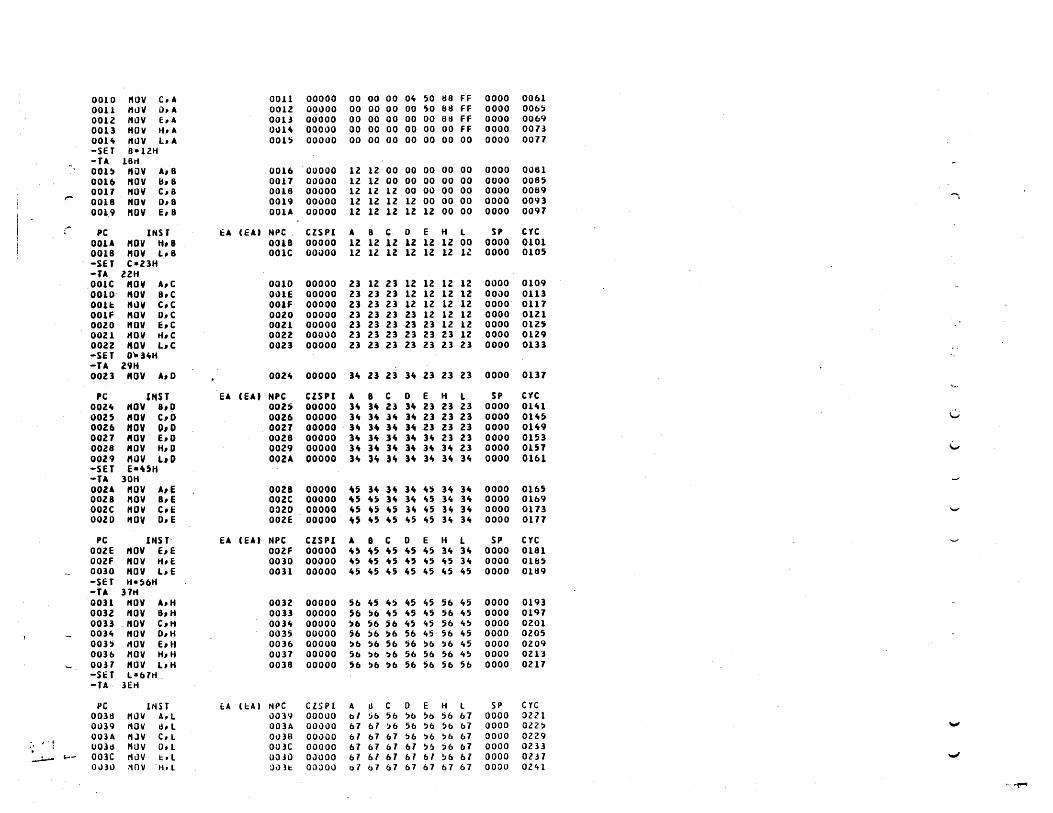
0010 HOV C.A 0011 00000 00 00 00 Oft 50 H8 FF 0000 0061 0011 HtlY a.A 0012 00000 00 00 00 00 0;0 813 FF 0000 006~
0012 HOY E, A 0013 00000 00 00 00 00 00 81t FF 0000 0069 0013 HOY H.A OIJH 00000 00 00 00 00 00 00 FF 0000 DOll OOH ,UlV L. A oon 00000 00 00 00 00 00 00 00 0000 0017 -SET B-12H -TA 18ri 001!J HilV A, B 0016 00000 12 12 00 00 00 00 00 0000 0081 OOU HOY lh8 0017 00000 lZ 12 00 00 00 00 00 0000 0085 0011 HOY e,8 0018 00000 12 12 lZ 00 00 00 00 0000 0009 .-0018 HOY 0,8 0019 00000 lZ 12 12 12 00 00 00 0000 0093
..... 0019 "OV E, B OOlA 00000 12 1l 12 12 12 00 00 0000 0091
PC INSf t:A (EU NPC _ eZSPI A 8 C 0 E H L SP eye 001A "OY H,8 0018 00000 lZ 12 12 1Z 12 12 00 0000 0101 0018 HOV LIB 001e OO~OO 12 12 12 12 lZ 12 II 0000 0105 -SET e-Z3H -TA l2H 001C HOY A,e 0010 00000 Z3 lZ Z3 12 12 lZ lZ 0000 0109 0010 HOY a,e DillE 00000 23 23 23 lZ lZ 12 12 OOJO 0113 DOH 'hlY c,e OOIF 00000 Z3 Z3 23 lZ 12 lZ lZ 0000 0111 OOlF HOV o,e 0020 00000 Z3 23- Zl 23 12 12 12 0000 Olll OOZO HOV E,e 0021 00000 23 23 23 23 Z3 lZ 12 0000 012!t OOZl HOV H,C 0022 00000 23 23 23 23 23 23 12 0000 0129 0022 HOV L,C 0023 00000 23 Z3_ 23 23 23 Zl 23 0000 0133 -SET O-HH -TA 29H 0023 HOV A,O 0021e 00000 )Ie 23 23 H 23 23 23 0000 0137
PC U4ST EA CEAt "PC CZSPl A 8 C 0 E H L SP eye OOZ" HOV 8,0 002S 00000 ]it n 23 3 .. 23 23 23 0000 OlU 0025 HOV C,D 0026 00000 lie 31t 1 .. 31t 23 23 23 0000 OH5 v 0026 "OV O,g 0021 00000 - 3' H 31t 31t 23 Z3 23 0000 o lit 9 0021 HOV - E,O 0028 00000 31t lit 31t 31t lit 23 23 0000 0153 0028 HOV H,O 00Z9 00000 3ft H 31t 31t H 3It 23 0000 0151 \..,
0029 HIlV L. () 002A 00000 )Ie 3ft lit H 3., 31t ]it 0000 0161 -seT _ E-UH -TA 30H 002A HOV A,E 0028 00000 U 3ft 3ft 3It It~ ]it )Ie 0000 0165 0028 HOV B. E 002e 00000 0\5 It~ 3ft 31t 1t5 3't 3ft 0000 0169 ooze HOY e,E 0020 00000 ~5 ~5 U 3ft It5 3ft lit 0000 0113 OOlO I10V O. E 002E 00000 ~~ ~5 <\5 1t5 1t5 lit lit 0000 0111
PC INS r- EA (EU NPC CZSPI A B C 0 E H L SP eye OOle HOV E, E OOlf 00000 It5 1t5 It5 It5 1t5 31t 31t 0000 0181 OOZf "OY H.E 0030 00000 ~~ lt5 U 0\5 1t5 "5 lie 0000 01U5 0030 HOV bE OOH 00000 It!) "5 itS 1t5 1t5 "5 1t5 0000 0169 -SET H-56H -TA 31H OOH "OV A.H 0032 00000 56 "5 It~ 1t5 1t5 56 1t5 0000 0193 003l "OV B, H 0033 00000 56 ~b "5 lt5 1t5 56 45 0000 0191 0033 HOV e,H OOH 00000 ~6 56 56 1t5 1t5 56 It~ 0000 alaI OOlle HOV O_H 0035 00000 56 !jb ~6 56 45, 56 "5 0000 0205 003~ t10V e, H 0036 00000 ~6 56 56 56 ~b ~6 1t5 0000 Ol09 0036 HOV H.H 0037 00000 5b ~b -~6 56 56 56 1t5 0000 all]
'- 00.31 HOV L,H 0038 00000 56 ~6 ~6 56 5b 56 56 0000 0217 -St:T La 61H, -TA· 3Eti
PC INH £:A 'I:A I NPC C lS P I A Ii C 0 E H l SP eyc 0038 HOV A,L ilOH 00000 bl :ib 56 56 50 56 67 0000 :>Z21 01J39 I'lOV Ii, L 003A 00000 67 61 :'6 56 56 56 67 0000 012~ """" OOlA MJV e,l OulB OOilOO 61 b7 67 56 56 56 67 0000 0229
," " ; UOH HUV 0, l 003C 00000 67 67 67 61 5!J 56 67 0000 Ol33 . ~ ~- 003C IillV I:tl O(HD 011000 61 bl b7 61 61 !l6 61 0000 0137 ~
01.131) 11nv H.L :)1131: OGOOO 07 b7 67 67 67 67 67 0000 OZ41
" -f"""

003E 11I.h/ l .. L 1l03F 00000 67 67 67 67 67 67 67 0000 02"5 --SP HH I
-fS 003F LXI HI ~0~1 O()H 00000 67 67 67 67 67 50 'H 0000 0255 00.,2 l.( I 0.3031 00.,5 00000 67 67 67 30 11 !JO H 0000 0265 001" LXI 8.1071 001,8 00000 61 70 11 30 31 50 51 0000 027!J
PC 1NSf .:A. lEAl NPC eZSPI A B e D E H L SP Cye ()
OO .. tJ LXI SP.ltOO\I 00..,8 00000 67 70 11 30 31 )0 51 40U 0285 004S HOV A .. H ,,",) 1 23 OO"C 00000 23 70 71 30 31 50 51 1t0U 029Z oo .. e lNI( H 001t0 00000 23 70 71 30 31 50 52 .. 041 0298 n 00"0 HOY thH 5052 13 OOH 00000 21 3l 71 30 31 50 52 .. 041 0305 oo"a; INI H OOH 00000 23 H 71 30 31 50 53 "OH 0)11 OO"F HOY e .. " ~O» Itlt 0050 00000 23 33 1tI. 30 31 50 53 "au 0318 ~
0050 INI H 00)1 00000 23 33 .... 30 31 SO 54 "OU 0324 OOS! PlOY 0, H 50H 5Z 0052 00000 23 33 "It 52 31 5t" 5" .. OH 0331 00)2 INI( H 0053 00000 23 33 H 52 31 50 55 "au 0337 (')
Don "OY E .. " )0)5 6l 005 .. 00000 23 H H 52 62 50 55 .. OH 03"" -PC INSf eA (EA) NPe CZSPI A B e D E H L SP eye . , 0054 IHX H 0055 00000 23 33 4" 52 62 )0 56 .. 041 0350 00)5 110V H,H 5056 17 0056 00000 23 33 "4 52 62 77 56 ..,ou O)H 0056 [NI H 0057 00000 Z3 33 It" 52 62 77 57 "OH 0363 :; 0057 I1UII L .. H 7757 76 0058 00000 23 33 It" 52 62 71 76 ItoH 0)70 -011 5600H 560FH 5600 16 76 16 16 16 76·76 16 16 76 76 76 76 16 76 76 .. : -fA 69H 0058 LXI H,5600 0058 00000 23 33 "" 52 62 56 00 "au 0180 ..... 0058 110Y H, A 5600 23 005C 00000 23 33 It" 52 62 56 00 4041 0387 005e [NX H 0050 00000 Z3 33 "" 52 62 56 01 "au 0393 0050 HOV H,8 5601 3l OOH 00000 23 33 .. " 5Z 6Z 56.01 "au 0400 005E INI H 005F 00000 23 33 .. " 52 ·bZ 56 02 40H 0"06 '"' 005F HOV ",C, 560l It It 0060 00000 23 33 "It 5l 6l 56 02 "OH 0413
PC INST EA CEA' NPC CZSPI A B e 0 E H L SP CYC ~ 0060 IN" H 0061 00000 23 3J "" 52 62 56 03 .. au 01tl9 OObI HOV PI,D 5603 S2 0062 00000 23 33 "" 52 62 56 03 ItOH 0"26 0062 INI H 0063 00000 Zl 13 .... 52 62 56 04 It 041 0432 -0063 HOV PI, E 560lt 62 006" 00000 Zl 33 .. " 5Z 62 ~6 Ole leaH OH9 006" IHX H 0065 00000 23 33 'tit 5Z b2 56 05 leaH OitU 0065 11011 ",H 560~ 56 0066 00000 23 11 .... 52 62 56 05 .. OH 01t52 "" 0066 INI H 0067 00000 21 33 ,... 52 62 56 06 ItOH 0"56 0061 HDV H .. l 56116 06 0068 00000 23 II "4 52 62 )6 06 .. au 0"65 0068 INK H 0069 00000 Z3
)3 "" 52 62 56 07 .. OH OU1 W
0069 I1VI ","6 5607 .. 6 OO~~ 00000 23 II ,,,,, 52 62 56 01 1t0H 0"81 -OH 5600H ~bOfH 5600 23 33 .... 52 62 56 06 ..6 76 76 16 16 16 76 76 76· W
-TA 8tlH
PC INSf t;A (EAI riPC ClSPI A B e 0 E H L SP cye w 0068 LXI 8,5056 OObE 00000' 23 50. 56 5Z 62 56 07 "OU OH1 006E LXI 0,5051 0071 00000 23 50 56 50 57 56 07 ItOH 0501 0071 lUAX B )0;6 77 0012 00000 77 50 56 50 51 56 01 ' ItOH 0~08 \0.1
0072 LOAl( 0 )\»)1 85 0013 00000 d) ~o )6 ~o H 56 07 ItOH OB5 0073 LDA )051i ~O)d DC 0076 00000 DC 50 ~6 50 51 !J6 01 1t0H 0~2ij
0016 HVI A, ,6 007tS 00000 ~b !JO ~6 50 57 56 07 ItOH 0535 -001d LX! I)' 5802 OOla 00000 56 50 56 5ts 02 56 07 itOH 0)1t5 0016 l.( I ti,5805 007E 00000 ~b 58 05 513 02 56 07 4041 0555 007E STU II 5BO:; :»6 :)OlF 00000 ~6 56 05 5d 02 56 07 1t041 0562 001F t1 III A,2) OJd1 00'"'00 25 56 O~ 58 02 56 07 4041 056'1
PC INST t:A lEAl N~C CZSPI A B C 0 E H L SP C vc WI'
0081 :i TA~ LI ,d1l2 25 0.;)82 OOOLIO 2) 5tS \)5 )6 OZ 56 01 4041 0)/6 ~ ... 00tl2 11 \I I A,ft: 0lld4 00000 Ft 58 05 )d 02 56 07 4041 05d) . " OOtS4 :iTA 5dOO ):JJJ fI: OOH OOJOO Fe )1$ 05 5tJ 02 56 07 4041 0)96 w ~ -=~
OOdl LilLO 'U~\l !.t .• J') 1 2J O\)~A 00,)00 FE 5d 05 ~d 02 23 22 4041 Obll
~ .. _t/¥tI~.~'~

ooc. ... StiLO ~IJOb 51:107 23 OOdD 00000 FE ~8 05 58 02 23 ZZ 4041 06ZIS -0" 5tjOOH ,80fH 5800 H 16 2!) 1b 16 )6 II 23 76 76 70 76 16 76 7b 76 -u li3H OOdD LXI SP,5b,0 0090 00000 FE 58 05 58 OZ Zl 22 5650 Ob38
0090 PUSH d ,'bH 05 OOli1 001100 FE )tJ 0) 58 02 l3 ZZ ,bitE 0650 0091 PUSH 0 5bitC 112 00'12 00000 FE ,11 05 58 OZ Zl ZZ 56itC Ob62
r 009Z PUSH H 56\A ZZ 0093 00000 FE 58 O~ 58 02 l3 22 56leA 0614 -' 0093 PUSH PSW 561e8 02 0094 00000 FE )0 05 ~6 02 23 ZZ 56.,0 06116
-0" 5bltOH 5650H 561e0 1b lb 7b 76 7b 16 76 76 02 FE 22 21 02 58 0, )6 5650 76
1 -T .,
PC ".Sf tA (Ell NPC CZSPl A II C 0 E H L SP CYC
I 009., POP H 56H FE 0095 00000 FE 58 05 58 02 FE 02 56ltA 06'16 00i5 PUP 8 5b"S Zl 0096 00000 FE 21 ZZ 58 02 H 02 56leC 0106 0096 POP PSIII 564D !i8 0097 00000 58 21 Z2 58 02 FE 02 5ME 0116 0097 POP D 564F 58 0098 00000 58 Zl Z2 58 05 FE 02 5650 .0726 -s.: T SP.5bItOH -T 1 0098 XCHG 0099 00000 ~8 23 2Z FE OZ 58 05 56.,D 0731t 009<1 )(THL 56ItE 58 009A 00000 511 Zl l2 FE 02 05 511 !i61e0 0150 009A $PHL 0098 00000 58 23 2Z FE 02 05 58 0558 0156 -. TeST ARITH"ETIC INHKUCTIONS -fA lUH 0098 "VI B,05 0090 00000 58 05 22 FE 02 05 58 0558 0763 00'10 "VI C,AO 009f 00000 58 05 AO FE 02 05 58 0558 0710 009F "VI 0, fF OOAl 00000 58 05 AO FF 02 05 58 0558 0111 .......
PC INST EA (Ell NPC CZSPI A 8 C 0 E H L SP CtC OOAl "VI E,50 OOAl 00000 58 05 AO FF 50 05 58 0558 0781e C 00A3 "VI H.zq 00A5 00000 58 05 AO FF 50 20 58 0558 0791 00A5 "VI L.02 OOAl 00000 58 O~ AO FF 50 20 02 0558 0198 OOAl AOO A 00A8 00101 80 05 AO FF 50 ZO 02 0558 0802 0 OOAe ADD B oon 00100 B!i 05 AO fF 50 ZO OZ 0558 0806 00A9 ADO C OOAA 10010 55 O~ AO FF 50 20 02 0558 0810 OOAA ADO 0 OOAB 10001 '4 O~ AO FF 50 20 02 0558 aSH 00A8 AUO E OOAC 00100 A., 0' AO FF 50 20 OZ 0558 0818 OOAC ADD H OOAD 00100 Cle O~ AO FF 50 ZO OZ 0558 OIiZZ OOAO ADD L OOle 00110 C6 05 AO FF 50 20 OZ 0558 0626 -
PC INSf EA (EAl NPC CZSPl A B C 0 E H L SP eyc OOAE ADI 01 0080 00100 C1 0' AO FF 50 ZO 02 0558 0833 OOBO ADI fF 00B2 .10111 C6 O~ AO fF 50 20 02 0558 08ltO 008Z ADe A 0083 10110 80 05 AO Ff ~o 20 OZ 0558 081t4 0083 ADC 8 OOS" 00111 93 05 AO FF 50 20 02 0558 OOltO -...I
OOS., ADC C 0085 10010 33 O~ AO FF 50 20 02 0558 0852 oon AOC 0 00B6 10011 31 05 AO FF 50 20 02 0558 0856 00B6 ADC E 0081 00110 84 05 AO FF 50 20 02 0558 0860 ..J
0081 ADC Ii 0088 00100 Ait 05 AO FF 50 ZO OZ 0558 0864 0088 ALJe L 0089 00110 Ab as AO Ff 50 20 02 0558 0868 0089 ACI 55 00B8 00100 FS 05 AO FF 50 ZO 02 0558 0875
PC INST EA 'EA) NPe CISPI A B e D E H l SP eyc - 0088 S8a A OOSC 01011 00 05 AO FF 50 20 02 0558 0819 008e SSIJ 8 OOBI> 10100 FB 05 AO Ff 50 20 OZ 0558 0883 0080 S8B C 00 at: 00011 5A 05 AO FF 50 20 OZ 0558 0881 008e S8a D ooaF 10000 )8 05 AO FF 50 20 OZ 0558 0891 008f StlS e OOCO 00011 OA 05 AO FF 50 20 02 0558 0895 OOCO sail H 00C1 10101 EA 05 AO Ff 50 20 02 0556 0699 OOC 1 idB L 00e2 00111 E1 05 AO Ff 50 20 02 05~6 0903
..., 00e2 SBI 01 OOCle 00101 Eo 05 AO FF 50 20 02 0558 0910 OOCle S81 FF 00C6 10110 E1 05 AO Ff 50 20 OZ 0558 0911
., ,I" "j V 00C6 SUS OOCl 01011 05 AO Ff 50 20 02 055B 09Z1
....., ~ A 00 ....;..--
"',~ 4 0lil':'

p, INH C4 'tAl .. PC CliPI A B C 0 E H L SP crc 00i; , SJS tl 00C6 10100 Fd O~ AO FF 50 20 02 0)56 0'125 OO'S SIJIJ C ,:,oe9 00001 )11 05 AD FF ~O 20 02 05511 0'129 00e9 SIJS IJ '1I1t A 10010 5C 05 AO FF 50 10 02 0558 0933 oDe A SUtS E ooed 00011 OC 05 AO fF 50 20 02 0)')8 0917 00C8 SJIl H ollec 10101 tc 0') AO FF 50 10 02 05511 O'l'el ooce SUB L OOCO 00101 fA 05 AO FF 50 20 02 0558 0'145 OOCO )UI 55 OOCF 00111 9') 05 AO FF 50 10 02 0558 0952 OOCf ANA A 0000 00111 95 115 AO FF 50 20 02 0556 095b 0000 "VI A,A') 0002 00111 A5 05 AO FF 50 20 02 0558 09b3 0002 ANA 8 0003 011011 05 05 AO FF 50 20 02 0558 09b7
PC 'NH t:A (EA) N'-C Cl)P1 A B C 0 E H L SP eye 0003 AI'lA e 0004 01011 00 O~ AO FF 50 20 02 0558 0971 0001t I1VI A, ,A OOOb 01011 5A 05 AO FF 50. 20 02 0558 0978 OOOb MfA D 01107 00011 )A 05 AO FF 50 10 OZ 0558 0'182 U007 ANA E 11008 00011 50 05 AO FF 50 ZO 02 0558 098b 0008 ANA Ii 0009 01011 00 05 AO FF 50 20 02 0558 0990 0009 I1VI A,FF 0008 01011 FF 05 AO FF 50 20 02 0558 0997 0008 ANA L OOOC 00001 02 05 AO FF 50 20 02 0558 1001 OOOC AIU 5') oooe 01011 00 05 AO FF 50 20 02 0558 1006 OOOE ORA A OOOF 01010 00 05 AO FF 50 ZO 02 0558 lOll OOOF OItA 8 OOEO 00010 05 05 Ail FF 50 20 02 0558 101b
PC INST EA (EA) NPC ClSPI A 8 C 0 E H L SP eye ~
oDeD ORA C ooEl 00110 A5 05 AD FF 50 20 02 0558 10lO I"
OOEl ORA D OOE2 00110 fF 05 AO FF 50 20 02 0558 1021t OOEZ I1VI A.OO OOE" 00110 00 05 AO FF 50 20 02 0558 1031 OOE" ORA E 00E5 00010 50 05 AO Ff 50 20 02 0558 1035 , DOE') ORA H OOEb 00000 10 05 AD FF 50 20 02 0558 1039 OOEb ORA L 00E7 00010 72 05 AO FF 50 20 02 05~8 10ltl 00E7 ORl 55 00E9 00010 77 05 AO FF 50 20 02 0558 1050 C. 00':9 lit A A OO':A 01010 00 05 AO fF 50 20 02 0558 10~" OOEA XItA 8 OOES 00010 05 05 AO fF 50 20 02 0556 1058 OOES XRA C ODEC 00110 A5 05 AD FF SD 20 02 0558 10b2 V
PC INSf t:A lEA) NPC elSPI A 8 C 0 E H L SP cye OOEC lKA 0 ODED 00010 5A 05 AO FF 50 20 02 0558 1066 ODED XltA E OOEE 00010 OA 05 ,AO fF 50 20 02 0')56 1070 OOtE '(IU H OOEf 00000 2A DS AO FF 50 20 02 0558 10H OOH XRA L OOFO 00010 28 as AO FF 50 20 02 0)58 1078 "."
OOfO IOU AA OOF2 00110 tlZ 05 AO FF 50 20 02 0558 1065 OOFZ CMP A OOF] 01011 8l O~ AO FF 50 20 02 OSS8 1069 00F3 CI1P 8 OOF" 00010 82 05 AO FF 50 20 02 0558 1093 ~
OOF" CI1P C OOF) 10111 82 05 AO FF 50 ZO 02 0558 1097 00f5 CI1P I) OOFb 10100 82 05 AO FF 50 20 02 055t1 1101 OOFb CI1P E 00F1 00001 82 DS AD fF 50 20 02 OS58 1105 ..,
PC INsr EA (EA) NPe CISPI A B e 0 E H L SP cYe OOf 1 CI1P H 00F8 00001 liZ os AO FF 50 20 02 0558 1109 W OOFtI CI1i» L 00F9 00101 81 as AD fF 50 20 02 055tt 1113 00.=9 CPI so OaFS 00001 tl2 05 AO fF 50 20 02 0558 1120 OOF8 LXI H,50H OOFE OOilOl 82 as AO FF 50 50 51 OS58 1130 ~
OOH AuD It 50,1 23 DOff 00110 A, 05 AO fF 50 ')0 51 0')56 1137 OOFf ADC " 50)1 21 0100 00100 Cd 0') AO fF 50 50 51 0558 11"" 0100 StSd 11 )051 21 0101 00111 AS 05 AD FF 50 50 51 0558 1151 i.,...
0101 SUB H 'O!IJ. II 0102 00111 til 05 AO FF 50 50 51 OS58 1158 0102 ANA 11 SOH lJ 0101 00001 02 05 AO FF 50 ,0 51 0558 llb5 0103 IlKA rt ~uH Zl 0101t OODOO Zl OJ AO ff 50 ,0 51 0556 111Z
PC INSf i:.A (bU NPC CZiPl A a C 0 E H L SP C 1e -...; 01D4 XU 11 ~O:H 23 010~ 01010 00 05 AO FF 50 50 ')1 0556 1119
".
,"-', 0105 CI1P 11 )0')1 23 0106 10110 00 0) AO FF 50 50 51 0556 lltt6 .~ 0106 LXi H,)100 0109 10110 00 05 AO Ff 50 51 00 05,tt 1196
vl0'l 1Nt( A JI0A 101100 01 0) AO FF 50 ')7 00 0558 1200 wi 010.\ 1 ~,( J OlJtj 11lJ11l 01 Ob 40 FF )0 )7 00 05')8 1Z04

OlOS INi{ C Oloe 10100 01 Ob Ai Ff ~il 51 00 0556 lZOtt .'1 aloe l,ii( 0 0100 11011 01 Db AI 00 50 57 00 0558 lZ12 0101l INR t; 010E 10000 01 Db Ai 00 51 57 00 05~8 121b OlOE INR H OlaF 10000 01 06 Ai 00 51 ~8 00 0558 lZ20 OIOF INR L 0110 10000 01 06 Ai 00 ~1 58 01 0558 lUte c;
- PC INST tA (EAI NPC CZSPI A 8 C 0 a: H L SP eye ... 0110 INK It 561>1 11 0111 10010 01 06 Ai 00 51 58 01 0558 12]1, Q
0111 lNR " 5801 lIS 0112 10010 01 0& Ai 00 51 58 01 ·0556 lH .. -0" )ttOOH )80fH . 5800 FE 78 l5 76 10 56 22 23 76 76 16 7b 76 76 76 76 " -TA 163H 0112 OCR A 0113 11011 00 Db A1 00 H 58 01 0558 12 .. d 0113 !Jell 8 Oll't 10011 00 05 At 00 51 58 01 0558 1252 ~ OlU OCR C 01U 10111 00 05 AO 00 51 58 01 0558 1256 OU5 DCK 0 0116 10110 00 0) AD FF 51 jO 01 0558 1260 0116 OCR E 0117 10011 00 05 AD FF 50 58 01 0558 126" n OU1 OCR H 0118 10001 00 05 AD FF 50 )7 01 0558 1268 0118 OCR L 0119 11011 00 05 AD FF 50 51 Ol' 0558 127Z 0119 OCR " 5700 75 DIU 10001 00 05 AD FF 50 51 00 0558 126l n
PC INSf EA (EA) "PC CISPI A. B C 0 E H l $P CYC DIU OCK " !i100 7 .. 011B 10011 00 05 AO FF 50 57 00 0558 1292 0 0118 ItVI A,ll 0110 10011 ZZ 05 AD FF 50 57 00 0558 1299 DU~ ADI .... 011F 00010 6b 05 AO FF 50 57 00 0558 1306 Ollf DAA OllO 00010 66 05 AD fF 50 51 00 0558 1310 0 OllO ADI 8d 01Zl 00110 ee 0' AO FF 50 51 00 0558 1311 012l OU 0123 10001 5lt 05 AD FF 50 57 00 0558 1321 0123 ettA 01 ZIt 10001 AS 05 AO FF )0 51 00 0558 1325 V Oil" STe 0125 10001 AS 05 AO FF 50 57 00 05,8 1329 0115 elte 0126 00001 AB 05 AO FF 50 57 00 0558 1333 0126 CltC 0111 10001 AB 05 AD FF 50 51 00 0558 1337 g
PC INS T EA (EU "PC CZSPI A B C 0 E H L SP eyc '- 0127 LXI B,10l0 01ZA 10001 A8 10 10 FF 50 57 00 0558 13ft 1 • OlZA LXI lJ,5AA~ 0120 10001 AB 10 10 SA A5 51 00 0558 1357
OllO DAD 8 01lE 00001 AS 10 10 5A A5 61 10 0558 1361 01ZE DAD D 01ZF 00001 AS 10 10 ~A A5 Cl 85 0558 1377 ~ OllF DAD H 0110 10001 AS 10 10 51. A5 83 6A 0558 1187 0130 DAD SP Olll 00001 AS 10 10 5A A5 88 CZ 0558 1391 0131 INK 8 0112 00001 A8 10 11 5A A5 ·88 CZ 0558 litO 3 .., 0132 INX 0 0133 00001 AB 10 11 5A At. 88 Cl 0558 H09 0133 INX H 013 .. 00001 AS 10 11 5A A6 88 C3 0558 1U5
..... 01H INX . SP 0115 00001 AS 10 11 SA A6 88 C3 0559 H21 " PC INST EA (EAI "PC CZSPI A 8 e 0 E H l SP eyc
\-. 0135 Dex B 0136 00001 AB 10 10 SA A6 88 C3 0559 HZ7 .-013b oex 0 0131 00001 AS 10 10 51 A5 88 C3 05~'I lit 33 0137 oex H 0118 00001 AB 10 10 5A. A5 88 Cl 0559 H39 0138 Del SP 0139 00001 A8 10 10 SA U 88 el 0558 lItte~ .. 0139 "~I A,5A 0118 00001 5A 10 10 5A A5 tl8 CZ 0558 H5Z 0138 RLC OBC 00001 B~ 10 10 !»A A5 68 ez 0558 lIt5b 013e KLC OBO 10001 69 10 10 5A A5 88 C2 0558 H60 • DUD RLC OHE 00001 DZ 10 10 5A A:; d8 CZ 0558 Hblt OllE IlLC OllF 10001 U 10 10 51. A5 88 ez 0558 H66 OllF RLC OHO 10001 te8 10 10 5A A!j 88 CZ 0558 H12 "
PC INST EA (EA) NPC ezsPI A B C 0 E H L SP eYe OHO IlLe OHl 00001 Qb 10 10 ~A A5 86 cz 0558 lH6 W
OH1 ~LC Olit2 10001 20 10 10 5A A5 dB e2 0558 lit 8 0 o lit 2 RLC 0143 00001 5A 10 10 5A A5 88 C2 0~58 HB4
"- Ollt] ~ItC 01ltlt 00001 Za) 10 10 5A A5 8B C2. 0558 H86 • f· . ( .J~ .•• '
01ltlt ~Re o lit 5 10001 'Ib 10 10 5A A5 au C2 0558 H9Z Ollt~ RRC Ol'tb 00001 ItS 10 10 5A A, tl8 CZ 0558 149b
.~ OHb Mite alit 7 10001 A5 10 10 5A A5 dB Cl 0558 1~00 W 0147 n(; 0148 10'JOl DZ 10 10 5A A5 ttR Cl 0558 l~Ote
. •. ~:;.. :.':,' ~', t\ . ,~. 11 It Ill'" ...... ,.._ "A::'"

Ol't~ RK(; 01ctA 10001 Oct 10 10 ,A A) Uti (;Z 0))0 1HZ ~ ,
PC !NST EA CEA) NPC CISP! A It C D E H L SP eYc OHA KRC OHB 00001 5A 10 10 5A A5 88 CZ 05511 1H6 0 OHB I(AL ollte 00001 B4 10 10 5A A5 B8 ez 0558 l~ZO
OUC RAL OHO 10001 611 10 10 5A A5 86 C2 0558 1524 OHO RAt aHE 00001 01 10 10 5A A~ 88 ez 0558 1528 0 OHE RAL OHf 10001 AZ 10 10 5A A5 88 CZ 0~58 1532 OHf ,UL 01~0 10001 45 10 10 ~A A~ 88 CZ 0558 U3b - 0150 RAL 0151 00001 86 10 10 5A A5 88 CZ 05)8 1~"0 0
4 01H RAt 0152 10001 16 10 10 5A A5 88 CZ 0558 15H OH2 RAt 01~] 00001 Zil 10 10 5A A!i 88 CZ 0558 15"8
I 01H ItU OU~ 00001 5A 10 10 5A A5 88 CZ 0558 1552 0 i
PC INST EA (EA) NPC CZSPI A B C 0 E H l SP cye OUit RAft 0155 00001 ZO 10 10 SA A5 88 e2 0558 1556 Q
0155 lUi 01~6 10001 16 10 10 5A A5 8b ez 0558 1560 OU6 RU 0151 00001 88 III 10 U A5 8B ez 0558 156" 0151 RAIl 0156 10001 ·u 10 10 5A AS 88 CZ 0558 1566 n 015B RAR OU9 10001 AZ 10 10 SA A5 88 ez 0558 1512 0159 RAR 015A 00001 01 10 10 SA A~ 88 ez 0558 157b 015A RAft 0158 10001 68 10 10 5A AS 88 CZ 0558 1580 • 01~8 RAR 01~C 00001 U 10 10 SA AS 8B CZ 0558 is 8" oue RAR 0150 00001 5A 10 10 5A " 88 ez 0558 1588 0150 J"P 0162 0162 00001 5A 10 10 5A AS 88 C2 0558 1598 •
PC INST EA (EA) NPC CZSPI A B C 0 E H l SP eyc ~ 016Z NOP 016] 00001 SA 10 10 5A AS 88 C2 0558 160Z 0
0163 NOP 016" 00001 SA 10 10 5A AS 88 CZ 0558 1606 -. TEST JU"P INSTRUCTIONS
U -seT ey·o.p·o.z·o.s-o • -TA 188H OUa" JC 0160 0167 00001 5A 10 10 5A AS 88 C2 0558 1613
v 0167 JZ 0160 016A 00001 5A 10 10 5A A5 88 CZ 0558 16Z0 • 016A JPE 0160 016D 00001 SA 10 10 SA AS 88 ez 0558 1627 016D J" 0160 0170 00001 U 10 10 5A AS 88 CZ 0558 16]10, 0170 .INC 01lb 0116 00001 SA 10 10 5A A5 88 ez 0558 16"" " 0176 JNI 017e 017C 00001 5A 10 10 5A AS 88 ez 0558 1654 011e .IPO 018l 018l 00001 U 10 10 5A A5 88 ez 0558 166" 018Z JP 0186 0188 00001 SA 10 10 5A AS 88 ez 0558 161" "
PC INST EA (EA) NPC CISPI , 8 C D E H L SP eye 018B NOP 0189 00001 SA 10 10 5A A5 88 C2 0558 1678 • -SET eY-l.p-l,Z-1.S-1 -fA 18,.H OUCl JNC 01bO 018C 11111 :;A 10 10 SA AS 88 e2 0558 Ib85 • OlBC JNZ 01bO 018F 11111 5A 10 10 SA AS 88 C2 0558 1b92 OUf JPO 0160 0192 11111 jA 10 10 5A AS 88 C2 0558 1699 0192 JP 0160 019!J 11111 SA 10 10 SA A~ 88 e2 0558 1106 • 0195 Je 019/S 0198 11111 ,A 10 10 SA A5 8tJ cz 0558 1116 0198 JZ OUI OU1 11111 :;A 10 10 5A AS 88 e2 0558 17Zb alAI JPt: OlA7 OlA7 11111 SA 10 10 5A AS 88 ez 0558 113b • I
OlA7 J" DIAD OlAO 11111 5A 10 10 5A A~ 8tJ ez 0558 17'tb OUD LXI H, 018,. OlBO 11111 )A 10 10 5A A5 01 B" 0558 115b •
PC INSf EA (EA' NPC CISPI A B e D E H L Sp cye alBa peHl 018" 11111 5A 10 10 SA A5 01 81t 0558 1162 018" CALL 5058 5056 11111 SA 10 10 5A A5 01 81t 055b 1780
.., -. It:;) , CAll ANt> REllJitli !NSTRIJC lIONS -SET Cy·o,p-o,z-o,s-o
v -TA leFH w r .. , ...... -•. i 505ts HUV AI IJ 505C \)0001 10 10 10 !iA A5 01 Bit 0~5b 116lt
~05C ItEl 0167 00001 10 10 10 5A A, 01 Bit 0558 1794 ~ ~ OlB7 CZ ,O'JU 018A 00il01 10 10 10 ~A AS 01 84 05~8 IH03 -.;
OliU CC "O,IJ 0180 OOJOI 10 10 10 SA A, 01 H4 0;58 IH2
........... ~"pt. , .... j ii

01CO Cft 5050 01C3 00001 10 10 10 5A AI) 01 Bt, 0558 1830 Cl 01e3 CrU !»O!»B ')058 00001 10 10 10 5A 15 01 Bt, 0556 Itf41J 505B HOV A,S 505C 00001 10. 10 10 5A A5 01 B4 0556 185Z
Q
PC INST EA (EA) NPC ClSP[ A 15 C 0 E H l SP eye 50SC RET 01Cb 00001 10 10 10 5A A5 01 Bt, 05')8 1862
(' 01C6 CNC 5058 5058 00001 10 10 10 5A A5 01 8t, 0556 Ideo 0 50)d ptOV A,8 505C 00001 10 10 10 5A AS 01 81t 0556 1884 505C ~I:T 01C9 00001 10 10 10 SA AS 01 8 .. 0558 1891t 01C9 CPO 5058 5058 00001 10 10 10 5A A5 01 8 .. 0556 11H2 C 50SS HOV A,8 505C 00001 10 10 10 5A 45 01 Bit 0556 1916 50)C RET 01Ce 00001 10 10 10 5A l5 01 Bit 0558 1926 01CC CP 5058 5058 00001 10 10 10 SA A5 01 81t 0556 19H 0 5058 HOV A,8 505C 00001 10 10 10 SA AS 01 81t 0556 19lt8 505e RET 01Cf 00001 10 10 10 SA A5 01 81t 0558 1958
0 PC [NST EA ( EA' NPC CZSPl A 8 C 0 E H L SP Cye
01CF NOP 0100 00001 10 10 10 5A AS 01 81t 0558 19bZ -SET Cya 1,pa 1,Za 1,Sal (')
-u 11;'" 0100 CI 5058 5058 11111 10 10 10 SA AS 01 8" 0556 1980 5058 HOV A, B 50SC 11111 10 10 10 SA A5 01 Ble 0556 198" 0 505C ReT 0103 lUll 10 10 10 SA 15 01 Bit 0558 199" 0103 ce 5058 5058 11111 10 10 10 51 AS 01 81t 0556 2012 5058 HOV ., B 505C 11111 10 10 10 SA A5 01 81t 0556 Z016 0 505e ReT 0106 11111 10 10 10 SA AS 01 U 0558 Z026 0106 CPE 5051 5058 11111 10 10 10 SA AS 01 8t, 0556 ZOH
(",., 5058 HOV A,8 50SC 11111 10 10 10 51 AS 01 Bit 0556 ZOlt8 2J 505C RET 0109 UIU 10 10 10 5A AS 01 Bit 0558 2058
0 PC INST EA CEU NPC CZSPI A 8 C 0 E H L SP CYC 0 Q109 '" ,o5, '058 11111 10 10 10 51 A5 01 81t 0556 Z016 5058 "OV ',8 505C 11111 10 10 10 SA 15 01 8" 0556 20ao
\...' 505C RET 010C 11111 10 10 10 5A AS 01 8~ 0558 Z090 • 01ut t,n ~O~D 01DF lUll 10 10 to SA A~ 01 Bit 0558 2099 010F tNt ~050 01EZ 11111 10 10 10 SA 15 01 alt 05~8 2108 _. 01EZ CPO 5050 alES 11111 10 10 10 SA U 01 8ft 0558 2111 • 0lE5 CP ~O~o 01EB lUll 10 .10 10 5A A5 01 Bit OSSB Z126 OlEa NOP 01E9 11111 10 10 10 5A AS 01 8 .. 0558 2130 -SET CYaO, P-O, Z-O,$aO • -TA ZOlH 01E9 CALL '05E S05E 00001 10 10 10 SA AS 01 Bt, 0556 2U8 ~OSE RZ 505F 00001 10 10 10 51 A5 01 8~ 0556 21St, •
PC INSf EA CEAI "PC CISPl A 8 C D E H L SP CYC
'- 505f RET 01EC 00001 10 10 10 SA A5 01 Bit 0558 216ft • OlEC CALL !:iObO 50bO 00001 10 10 10 SA A5 01 Bft 0556 Z18Z ~ObO ItC 5061 00001 10 10 10 5A AS 01 8 .. 0556 Z188 5061 RET 01EF 00001 10 10 10 5A AS 01 8~ 0558 Z198 • ~
OleF CALL :i06Z 50b2 00001 10 10 10 SA AS 01 tllt 055b 2Z16 50b2 RPE 50b3 00001 10 10 10 5A A5 01 Bit 0556 2ZZZ
1 50b3 RET 01FZ 00001 10 10 10 SA AS 01 B .. 0558 2232 • 01fZ CALL !iOb~ 506le 00001 10 10 10 ~A A5 01 Bt, 0~56 2250 S06~ It" 50b5 001101 10 10 10 5A A5 01 8" 0556 ZZ56 ~
SOU RET OlF5 00001 10 10 10 H AS 01 8" 0558 2266 • r PC INSf EA (EAt NPC CZSPl A 8 C 0 E H L SP CYC
01fS CALL 5066 506b 00001 10 10 10 SA A~ 01 Bt, 055b US" ... 50b6 KNZ 01FS 00001 10 10 10 5A A~ 01 81t 05)8 2296 01f8 CALL 50b8 5068 00001 10 10 10 SA A5 01 Bit 05~6 Z311t ~,
V ~Ob8 ItNC OlF8 00001 10 10 10 SA A5 01 81t 055d Z3Z6 • I
.~ 01FB CALL ~06A 50bA 00001 10 10 10 5A A5 01 81t 0556 Z34ft
'). .. ,. 50bA RPO OlFE 00001 10 10 10 5A A~ 01 Bit 0558 ZH6
"- 01FE CALL !1llbC SObC 00001 10 10 10 5A A5 01 Bft 0556 Z3 ]I, W 50be KP OZOl 00001 10 10 10 5A A5 01 Bit 05~8 2386 .. ~

505E RI 0201t 11111 10 10 10 SA AS 01 Bit 055B 241b
PC 'NSf I:A (EA) NPC ClSP 1 A B C [) E H L SP eYe 020t, CALL 50bO ~UbO 11111 10 '10 10 SA A5 01 Bt, 0556 Z'tlt, 50bO RC 0207 11111 10 10 10 SA A5 01 Bit OS)8 2Hb 0207 CALL 50b2 5062 11111 10 10 10 SA A5 01 Bit 0556 Zlt6it S06l RPE 020A lUll 10 10 10 5A A5 01 Bit 0558 2it7b
;- OlOA CALL !l061t 50blt 11111 10 10 10 5A AS 01 Bit 0556 Zit 9 it ~Ob" R" OZOO 11111 10 10 10 5A A5 01 Bit 0558 250b 0200 CALL 506b 506b lll11 .10 10 10 5A AS' 01 Bit 055b 25Zlt .. : 'Obb RNZ 5067 11111 10 10 10 5A AS 01 Bit 0556 2530 50b7 ItET 0210 11111 10 10 10 5A AS 01 Bit 0558 2HO 0210 CALL 5068 5068 11111 10 10 10 SA A5 01 Bit 0556 2558
PC INS T EA C EA' NPC CISPI A B C D E H .:.. SP evc 5068 RMC 5069 11111 10 10 10 SA AS 01 Bit 0556 2561t 5069 RET 0213 11111 10 10 10 5A 'AS 01 Bit 0558 2571t OZU CALL 506A 506A 11111 10 10 10 5A AS 01 Bit 0556 25n 506A RPD 506B 11111 10 10 10 SA AS 01 Bit 0556 2598 )06B RET OZ16 11111 10 10 10 SA AS 01 U 0558 2608 0216 CALL 50bC 506C 11111 10 10 10 SA A5 01 Bt, 0556 2626 50be RP 5060 11111 10 10 10 SA AS 01 Bit 0556 2b3Z 5060 RET OZl9 11111 10 10 10 SA AS 01 Bit 0558 26ltZ OZ19 RST 00 0000 11111 10 10 10 5A AS 01 Bit 0556 265" -T 2 0000 "VI A,Ol 0002 11111 01 10 10 SA U 01 Bit 0556 2661
PC INST EA 'EA) NPe CZSPI A B e 0 E H L SP eve OOOZ "VI 8,Ol OOOle 11111 01 02 10 SA AS 01 n 0556 2668 0 -OH SObS 01F5 0 50b6 01F8 50b8 ; ......
OlfB 506A OlFE V 506C OlOl 505E U OlD It 5060 Ol07 ~
50b2 OlOA 50blt \.J
OlOO 506b 50b7
...., OliO 50b8
'-' 50b9 '-'
0213 506A 50bB 021b !lObC 50bl> w t
0219
-,. '~1 0000 ) .. U 0002 \.I
~ -. TI:) T NUIU1AL PJI<T I/J IN.iIRUCTIONS
.--,- .. .". ... ~~ .. -. ......,......
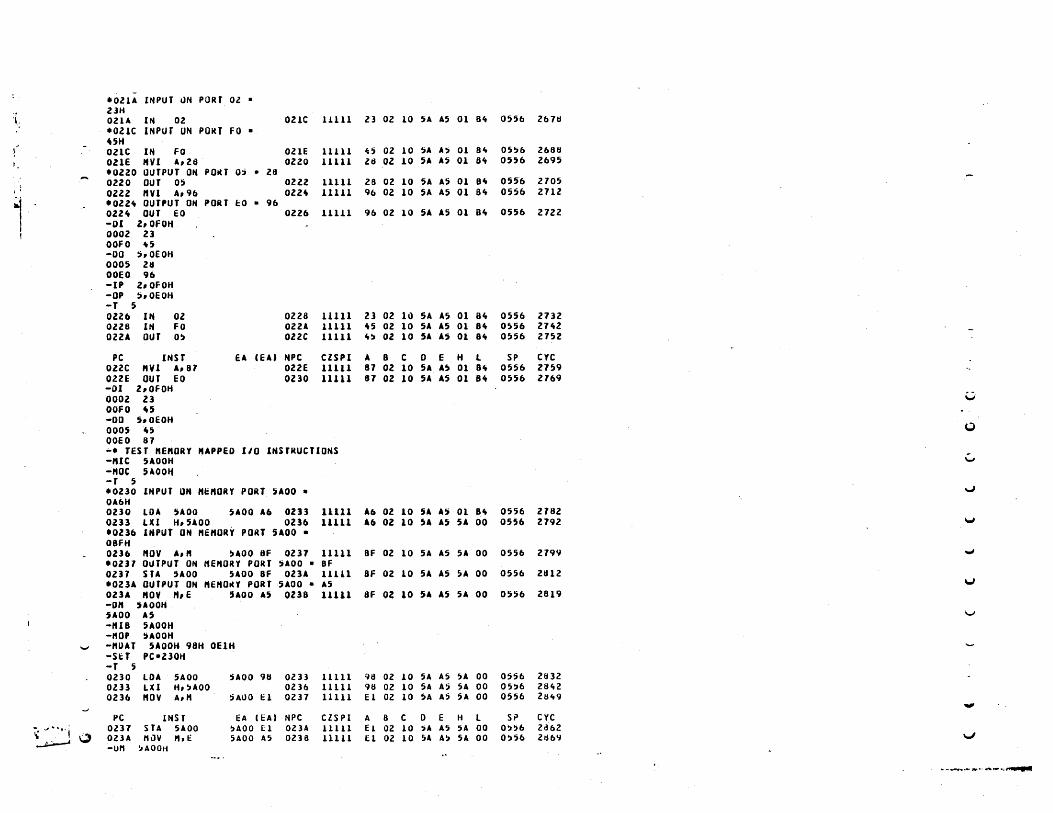
.. ·OZIA INPUT I1N PORT 02 • 21H
'l- OZlA lit 02 021C lUll 23 02 10 5A AS 01 Bit 0556 2618 .Olle INPur UN POHf fO • UH 021C IN fO 021E 11111 4) 02 10 5A A) 01 Bit O~!)b 2688 OZlE HVI A,ll) Ol20 11111 Zit OZ 10 5A A~ 01 Oft OH6 2695 .0220 OUTPUT ON POIU 0; • 28
, , 0220 OUT 05 0212 11111 28 02 10 SA A5 01 B" 0556 2105 , ' 02Zl "VI A,96 Oll<\ 11Ul 96 Ol 10 5A AS 01 81t 0556 2H2
I .Oll" OUTPUT ON PORT 1:0 • 96 022" OUT EO 0226 11111 96 02 10 SA AS 01 Bit 0556 l1Zl -DI l,OfOH
! OOOl 23 OOfO -\5 -DO :;,OEOH 0005 26 OOEO 96 -IP Z,OfOH -OP 5,OEOH -T 5 02Z6 IN Ol ozza lUll 23 02 10 SA A5 01 8" 0556 Z732 Ol28 IN Fa 0221 11111 <\5 02 10 5A AS 01 8" 0556 2H2 OllA OUT O~ 022C 11111 It~ OZ 10 5A A5 01 Bit 0556 2152
PC INST EA (EA) NPC elSPI A 8 e 0 E H l SP eYe 022C "VI A, B1 OZ2E 11111 81 02 10 5A A5 01 8ft 0556 2159 Ol2E OUT EO OZ30 lUll 81 02 10 SA 15 01 Bit 0556 2169 -01 Z,OFOH 0002 23 ~
OOFO <\S -DO 5,OEOH 0005 "5 0 OOEO 81 -. TEST KE"ORY NAPPED 1/0 INSTRUCTIONS -"Ie 5AOOH '-' -NOC ~AOOH -T 5 .0230 INPUT UN Ht:HOIU PORT UOO • \oJ
OA6H 0230 LOA !)A 00 5AOO A6 OZB 11111 A6 Ol 10 5A A~ 01 Bit 0556 2182 0233 LXI H,5AOO Ol36 11111 A6 Ol 10 5A A5 SA 00 0556 279l 'owl
t0236 INPUT ON "EHORY PORT 5AOO • OBFH 0116 HOV A, " !lAOO Sf Ol31 11111 BF 02 10 SA AS SA 00 0556 2199 .J
·0231 OUTPUT ON HEHORY PORT ~AOO • BF 0237 SU 5AOO SAOO BF 02lA 11111 BF 02 10 5A AS 5A 00 0556 2t11Z t023A OUTPUT ON HEHOItY PORT 5AOO • AS V
OllA NOV H, E 'AOO A5 DUB lUll SF 02 10 SA A5 5A 00 0556 2819 -OH UOOH UOO AS v -IUB 5AOOH -HOP 5AOOH - -HUAT 5AOOH 98H OElH -S&:T PC·Z30H -T 5 0230 LDA 5AOO HOO 96 OZB 11111 9t1 OZ 10 5A AS ~A 00 0556 2832 OlB LXI H,!)AOO OZ 36 11111 98 02 10 SA A5 SA 00 05~6 Z8ltZ 0236 ptOV A," ~AOO H 0231 11111 El Ol 10 SA A' SA 00 0556 2Slt9
.."
PC INSf EA (EA) NPe elSPI A 8 C 0 E H l SP eYe
~ "·"-1 OZ37 STA 5AOO !JAOO El OZ3A 11111 E1 02 10 ;A A5 5A 00 O)~b Zd62 0 OZlA tlllV ",E SAOO AS OZ38 11111 E1 02 10 5A A!) SA 00 O!J56 Zd61i V
~ -Uti ~AOOtt
.. - .......... ,. ......... .,............

- - - - -------- ----OUt
"t a 00000000 sao a 0 INT1.S • 0 -T 3 OllB RUt OllC lUll 00 02 10 5A A, 5A 00 05S& 2d73 OllC "VI A"CF 023E 11111 Cf 02 10 5A A5 5A 00 0556 2660 021E SI" 023F 11111 Cf 02 10 SA A5 !lA 00 05~b 268" '-_.
-0'" U a OOOOQl11 SOD a 1 INT7.S a 0 -SET Sial -DI"
I" a 10000Ul SOil a I INn.5 a 0 -T I 02lf RI" 02"0 11111 81 02 10 5A A~ 5A 00 0556 2888 -SIB -SDAr o 1 1 0 -r 5 Ol"O RI" OlU 11111 01 02 10 5A AS 5A 00 0556 Z892 alit 1 RI" 02"2 11111 87 02 10 5A AS 5A 00 0556 ZII96 OZ"Z RIH OZIt) 11111 87 02 10 SA A5 5A 00 0556 Z900 OZ"3 RI" 02"" 11111 07 02 10 SA A5 SA 00 0556 Z90.
PC INST fA (EAt NPC CZSPI A 8 C D E H L SP cye OZ"" RI" o lit 5 11111 01 OZ 10 5A AS 5A 00 0556 2908 -SeT PC·ZltOH -T 5 Ol"O RUt OZU lUll 81 02 10 " AS 51 00 0556 291Z 02 It! RlH 02"Z lUll 87 OZ 10 SA A~ SA 00 0556 2916 02"Z RI" 02"3 11111 07 OZ 10 5A U 5A 00 0~56 Z920 02"3 KU Ol"" 11111 07 02 10 5A AS 5A 00 0556 29Z" 02"" RI" . Ol'" 11111 81 OZ 10 'A A5 5A 00 0556 2928 U -SIC -soc -T 5 0 ·OZ"5 SEKIAL INPUT • 1 OZU RI" OUb l11U 87 Ol 10 SA A5 SA 00 0556 293Z \.I 02"6 "VI A"CO OZ"8 UUl CO 02 10 5A A5 SA 00 0556 2939
.• 02U SERIAL OUTPUT - 1 02,,8 SI" OZ"9 lUll CO 02 10 SA AS 5A 00 0556 29"3 \J
02"9 "VI A,80 02U UUI 80 02 10 5A A5 SA 00 0556 2950
" INST EA (EAI NPC CZSPI A B C D E H L SP CYC ...J oz,a $I" 02"1; HIU 80 02 10 S~ AS ~A 00 0556 Z95ft -. TEST VARIOUS INTERRUPTS -INT I 7 OC3H 11tH Oltt ...; -SET lEal -T " OZ", HOV A,8 OZloeD lUll 02 Ol 10 5A AS SA 00 0556 2958 V
••• INTERRUPT RECOGNIZED OZ"O HOV 0, B 02U lUll 02 02 10 OZ A5 5A 00 0556 29b2 02"£ J"' 011" 01H lUll 02 02 10 02 AS 5A 00 05!16 2972 V
017" "OV H,8 0175 11111 02 02 10 02 A5 02 00 0556 2916 -SET PC-ZitCH
...... -IIH , Z -T " ••• INTERRUPT KECOGNIHD OlitC "OV A"S OOZ" 11111 02 OZ 10 02 A5 02 00 05!1" 2993 OOZit HOV 8,0 OOZ, lUU 02 OZ 10 OZ A5 02 00 055't Z997 OOZ!; "ov C,D 00Z6 11111 02 OZ OZ OZ A!I oz 00 0551t 3001
\...- 0016 MDV 0,,0 00Z7 11111 02 02 02 02 A) 02 00 05!1" 100!l W -SET PCaZ'tCH
-., ,;I ... ·.I~ -. THIS INTERItUPT .. Ill NUT U RECOiiNLZED SINCE ENABLE BIT [S RESET ) ... , y -INT I Z 0 ~ ~ -T ,.
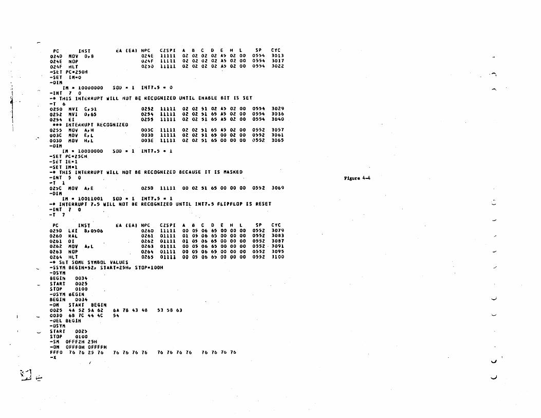
PC I"sr t:A (EAt NPC CZSPI A B C 0 E H l SP eyc 02,,0 .. OV o. B 02"E 11111 02 02 02 02 A~ 02 00 055" 3013 021tE NOP Ol4F lUll 02 02 02 02 A5 02 00 055" 3017 021tF HLT OZ)1l 11111 02 02 02 02 A, 02 00 05H 302Z -SET PC a2S0H ...... -SET 1"-0 -01"
I I.. • 10000000 SOU - 1 un., - 0 'j ......
i -INT 1 0 -. THIS IHTtRRUPT WILL liDT BE RECOGNIZED UNTIL ENABLE BIT IS SET -T 6 0250 .. VI C, :i1 OZS2 11111 02 02 H 02 A~ 02 00 055~ 3029 0252 .. VI 0,65 025 .. 11111 02 02 n 65 AS 02 00 055" 3036
I 025" El 02n 11111 02 02 51 65 A5 02 00 055ft 30"0 ••• INTEKIWPT RECOGNIZED
02S5 "OV AI H 003C 11111 02 02 U 65 AS 02 00 0552 1057 003C "OV e. L 0030 11111 02 02 51 65 00 02 00 0~52 30&1 0030 .. OV H,L 003E 11111 02 02 n 65 00 00 00 (\552 3065 -01"
I" a 10000000 SOD a 1 INn.5 a 1 -SET PC-25CH -SiT IE-I -SET l"a1 -. THIS INTERRUPT WiLL NOT BE RECOGNIZED BECAUSE IT IS "ASKED -1NT , 0 risun 4-4 -T 1 02~C "0" AI e 0250 11111 00 02 51 65 00 00 00 05!'iZ 3069 -01"
I" • 10011001 SOD - I INT1.5 - 1 -. INTERRUPT 1.5 WILL NOT BE RECOGNIZED UHTlL INT1.5 FLIPFLOP IS RESET -lin 7 0 -T 7
PC INSf t:A , EAI NPC CZSPI A B C 0 E H l SP CYC 0250 lU B, 0~06 Ol60 11111 00 os 06 65 00 00 00 0552 3079 0260 IUL 0261 01111 01 os 06 65 00 00 00 0552 3083 OZ61 01 0262 01111 01 05 06 65 00 00 00 0552 3081 ' 0262 .. 011 AIL 0263 01111 00 os 06 65 00 00 00 0552 3091 0263 NOP 026" 01111 DO 05 06 65 DO 00 00 0552 ]095 026\ HLl 02U DUll 00 05 Db 6) 00 00 00 0552 1100 -. S~T SO"~ SY"BOL VALUES -55Y" BEGIN-52, SlART-25H. STOP-100H .-'
-OS," BEGI~ DOH START Don STOP 0100 -I)S'" IiEG". BEGIN OOlft ....)
-0" STAItT BEGIN 0025 "A 52 SA 62 6A 18 It3 le8 5] 58 63 0030 68 1C " .. ItC 51t -!lEt BEGIN -on .. START 002) STOP 0100 -S" Offf2H 25H -0" OFFFOH OffFFH ffFO 16 16 25 16 16 1& 1& 7& 76 16 16 16 16 16 16 76 -x
V
": .. -~ ~ .....J

APPENDIX A
SIMULATOR MESSAGES
Simulator messages are divided into two classes; Command Mode
messages and Execution Mode messages. Most messages indicate errors
although some are merely informative. In the interactive mode,
all error messages cause the Simulator to return to the Command Mode
and cause the program to revert to using the standard I/O devices. In
the batch mode, all errors cause the Simulation Program to terminate.
The following messages are considered as errors unless stated
otherwise:
Command Messages
ADDRESS OUT OF RANGE - An operand that represents a memory address
that is too large. The maximum memory address has been exceeded
during a set memory command. The load address specified in an
object module record is greater than available memory.
ARGUMENT ERROR - a command argument contains an invalid character.
The user has specified a numeric that contains a character not
valid for this numeric base.
CHECKSUM ERROR - object module contains a checksum error. User
should reassemble source program to obtain new object module.
DATA TABLE ERROR - user has specified more data values than can be
contained in the data table.
END OF FILE ENCOUNTERED - in the batch mode, an end-of-file (EOF)
condition was detected while reading commands.
FILE NOT FOUND - a file name specified in the R, RD, RE, RED, W, L, or
LS commands could not be found or opened.
5-1
INVALID CHARACTER - an invalid character was found while processing
a command line.
INVALID COMMAND - the user specified command is not valid. See
Command Summary.
INVALID ELEMENT - an invalid element was specified with the S or
SET command.
INVALID OPERAND - a command operand was invalid.
LIMIT REACHED - This is an informative message only. It indicates
that the number of instructions specified by the LI command has
been executed. This message only occurs when the T, TA, TB, E, or
EA command is used to initiate program execution.
MISSING OPERAND - the command requires an operand(s) but none was
specified.
NUMBER OF BYTES READ = - this is an informative message that
indicates the number of bytes read in the object module by the L
or LS commands. If the number of bytes read is zero, it probably
indicates that an object module of the wrong format was read.
SYMBOL ERROR - a symbol in the object module was invalid. A symbol
specified in the DSYM or SSYM commands started with a numeric
character or contained an illegal character.
SYMBOL FORMAT ERROR - a symbol record in the object module specified
. a symbol with no corresponding value.
SYMBOL TABLE FULL - an attempt is made to place t~o many symbols
into the symbol table. If this message occurs while reading an
object module, it is an informative message only, but any remaining
symbols are ignored .. The user may increase the size of the symbol table.
SYNTAX ERROR - the user has specified an operand that contains
invalid syntax. For example: 3+-5, LABEL/3
5-2
TERMINATOR ERROR- an invalid terminator was specified for an operand.
E.G. SSYM LABEL*- 56H
UNDEFINED SYMBOL - a symbolic operand was specified that is not in
the symbol table.
VALUE OUT OF RANGE - a value has been specified that is too large. A
byte value is greater than 255. An element consisting of 1 bit
, is greater than 1.
Execution Messages
ADDRESS OUT OF RANGE - the program counter exceeds the legal
maximum.
DATA TABLE ERROR - an attempt has been made to read data from the
data buffer ,table for a port for which no data has been defined
by the DATA command. In the batch mode, this is an informative
message only; the value of the accumulator does not change and
execution proceeds. In the interactive mode, this is an error message.
ILLEGAL INSTRUCTION - an attempt has been made to ,execute an
illeg'al instruction.
INVALID INPUT DATA - the user has entered inpu~ data for an input I
port that is out of range or is an illegal numeric. This message
will only appear in the batch mode or in a read mode.
WRITING TO PROTECTED MEMORY - the Simulator has executed a micro
processor instruction that writes to protected memory.
5-3

APPENDIX B
COMMAND SUMMARY
The following list is a summary of the 8080/8085 Simulator
commands.
* - Comment
- Comment
BASE - Set Numeric Input Base
BP - Set Address Breakpoint
DATA - Specify Input Buffer Data for Normal I/O Ports
DC - Display CPU Status
DEL - Delete Symbols
DR - Display History
DIM - Display Interrupt Mask
DIN - Display Input Port
DM - Display Program Memory
DOUT - Display Output Port
DSYM - Display Symbols
E - Execute Instructions
EA - Execute Instructions Until Address
FIN - Fill Input Port
FM - Fill Program Memory
FORM - Set Display Line Format
FOUT - Fill Output Port
- Specify Heading Count
- Read Port Input Data from
- Read Port Input Data from
- Set Instruction Interrupt
Data Buffer
Current Input Device
H
IB
IC
INT
IP
IS
L
- Read Port Input Data from Preset Data Latch
- Read Port Input Data from Standard Input Device
- Load Obj ec t Module
LI - Set Instruction Execution Limit
LS - Load Object Module with Symbol Table
5-4

MDAT - Specify Input Buffer Data for Memory Mapped I/O ports
MIB - Read Memory Input Port Data from Data Buffer
MIC - Read Memory Input Port Data from Current Input Device
MIP - Read Memory Input Port Data from Preset Data Latch
MIS - Read Memory Input Port Data from Standard Input Device
MOC - Write Memory Mapped Output Port Data to Current Output Device
MOP - Write Memory Mapped Output Port Data to Data Latch
MOS - Write Memory Mapped Output Port Data to Standard Output Device
NBP - Clear Address Breakpoint
NINT - Clear Instruction Interrupt
NPRO - Clear Memory Protect Flags
NTR - Clear Address Trace Flags
- Write Output Data to Current Output Device
- Write Output Data to Data Latch
OC
OP
OS
PRO
R
RD
RE
- Write Output Data to Standard Output Device
- Set Protect Flag for Address Range
- Read Commands from· Alternate Input Device or File
- Read Commands with Delay
- Read Commands with Echo
RED - Read Commands with Echo and Delay
RES - Reset Microprocessor
RET - Return from Read Mode, Read Commands from Standard Input Device
SDAT - Specify Input Buffer Data for Serial Port
SET - Set Processor Element (Registers, Status Bits, etc.)
SIB - Read Serial Input Port Data from Data Buffer
SIC - Read Serial Input Port Data from Current Input Device
SIN - Set Input Port Data Value
SIP - Read Serial Input Port Data from Preset Data Latch
SIS - Read Serial Input Port Data from Standard Input Device
SM - Set Program Memory
5-5

soc SOP
SOS
SOUT
SSYM
T
- Write Serial Output Port Data
- Write Serial Output Port Data
- Write Serial Output Port Data
Set Output Port Data Value
- Set Symbols
- Trace Instructions
to
to
to
TA - Trace Instructions until Address
Current Output
Data Latch
Standard Output
TB - Trace Instructions with Breakpoints
TR - Trace Flags for Address Range
TYPE - Specify Processor Type
W - Write Output to Alternate Device or File
X - Exit Simulator
5-6
Device
Device

APPENDIX C
OBJECT MODULE FORMATS
The object module is a machine readable computer output in
the form of punched cards, paper tape, etc. The object module
contains specifications for loading the memory of the target micro
processor. The object module is produced as a series of card images
by Microtec's 8080/8085 Macro Assembler or any other compatible assembler.
Each object record contains the load address and data specifications
for up to 255 bytes of data. Symbol table information may also be
included. The format of an object module is shown below.
$$ symbol records
$$ data records
A record consisting of two dollar signs indicates symbol records
follow. A sample symbol record is shown below:
APPLE 00000H LABELl 0D0C3H MEM 0FFFFH
A symbol record consists of up to four symbols, with each symbol's
value immediately following "the symbol. The symbol and symbol values
must be separated by at least one blank. If the symbol's value is in
a base other than decimal, a single letter descriptor must follow the
value; "H" for hexadecimal, "Q" for Octal. A second record consisting
of two dollar signs follows the last symbol record.
The format of a data record is shown below.
1 2 3 4 5 6 7 8 9 10 11
byte count
load address
type data
5-7
40 41 42 43
data checksum

Column 1 contains the code for a colon. This marks the beginning
of an object data record.
Column 2 and 3 contain the count of the number of data bytes contained
in the record. If this field contains an "00" it signifies the end
of the object module.
Columns 4 through 7 contain the load address expressed as hexadecimal
digits. The first data byte is to be loaded into this address,
subsequent data bytes into the next sequential addresses. Columns
4 and 5 contain the most significant byte of the address.
Columns 8 and 9 contain the record type. Presently two types are
defined. "00" indicates a data record. "01" indicates a terminator
record. In this case the byte count will also be zero and the load
address will contain the module starting address.
Columns 10 to 41 (more or less depending upon number of data bytes)
contain the hexadecimal specifications for up to 16 bytes of data.
The last two columns in the record contain a checksum. The checksum
is the negative of the sum of all bytes in the record (except column
1) evaluated modulo 256. Thus when the record is read, the sum of
all bytes, including the checksum, should be zero.
5-8

APPENDIX D
8080/8085 OPERATION CODES
The following table illustrates the proper format for
writing 8080/8085 instructions. The operation code mnemonics
listed are the only valid opcodes for the assembler.
These symbols are used in the table.
D,S - indicates a source or destination register which
is one of the following: A,B,C,D,E,H,L,M
RP - indicates a register pair which may be one of the
following: B,D,H,SP
PSW - indicates the Program Status Word
eXPa - indicates an 8 bit value
eXP 16 - indicates a 16 bit value
ddd - ~he bit pattern repres~nting one of the registers
555 denoted by D or S above. The bit patterns are as
follows:
B - 000
E - all
M - 110
c - 001
H - 100
A-Ill
D - 010
L - 101
rp - the bit pattern representing one of the register
pairs denoted by RP above. The bit patte~ns are as
follows:
B.- 00 D - 01 H - 10 SP - 11
* - new instruction of 8085
When two states are shown for an instruction, the first
number is if the condition is not satisfied and the second
number is if the condition is satisfied.
5-9

SYMBOLIC FIRST BYTE NUMBER NUMBER OPCODE MACHINE CODE OF BYTES OF STATES
S080 80S5
Data Transfer
MOV D,S 01dddsss 1 5 4 MOV D,M 01dddll0 1 7 7 MOV M,S 01110sss 1 7 7 MVI ,0, exPS 00dddl10 2 7 7 MV'I M,ex p
S 00110110 2 10 10
LXI RP,ex 16 OOrpOOOl 3 10 1 0 LOA eXP16 00111010 3 1 3 1 3 STA eXP16 00110010 3 1 3 1 3 LHLD eXP16 00101010 3 1 6 1 6 SHLD eXP16 00100010 3 16 1 6 LDAX RP 00rpl010 1 7 7 STAX RP 00rp0010 1 7 7 XCHG 11101011 1 4 4
Arithmetic GrouE
ADD S 10000sss 1 4 4 ADC S 10001sss 1 4 4 SUB S 10010sss 1 4 4 SBB S 10011sss 1 4 4 AD I exPS 11000110 2 7 7 AC I exPS 11001110 2 7 7 SUI exPS 11010110 2 7 7 SBI ,exps 11011110 2 7 7 INR 0 00dddl00' 1 5 4 OCR 0 00dddl01 1 5 4 INX RP OOrpOOll 1 5 6 DCX RP 00rpl011 1 5 6 DAD RP 00rp1001 1 10 1 a DAA 00100111 1 4 4
Lo~ical GrouE
ANA S 10100sss 1 4 4 XRA S 10101 s s s 1 4 4 ORA S 10110sss 1 4 4 CMP S 10111sss 1 4 4 ANI exPS 11100110 2 7 7 XRI exPS 11101110 2 7 7 ORI exPS 11110110 2 7 7 CPI exPS 11111110 2 7 7 RLC 00000111 1 4 4 RRC 00001111 1 4 4 RAL 00010111 1 4 4 RAR 00011111 1 4 4 CMA 00101111 1 4 4 CMC 00111111 1 4 4 STC 00110111 1 4 4

SYMB.oLIC FIRST BYTE NUMBER NUMBER .oPC.oDE MACHINE C.oDE OF BYTES .oF STATES
8.080 8.085
Branch Group
JMP eXP16 11.0.0.0.011 3 10 1 .0 J NZ eXP16 11.0.0.0.01.0 3 1 .0 7/1.0 JZ eXP 16 11.0.01.01.0 3 1 .0 7/1.0 J NC eXP 16 11.01.0.01.0 3 1 .0 7/1.0 JC eXP 16 11.011.01.0 3 1 .0 7/1.0 J P.o eXP 16 111.0.0.01.0 3 1.0 7/1.0 J PE eXP 16 111.01.01.0 3 1 .0 7/1.0 JP eXP 16 1111.0.01.0 3 1.0 7/1.0 JM eXP 16 11111.01.0 3 1.0 7/1.0 CALL eXP 16 11.0.011.01 3 1 7 1 8 CNZ eXP 16 11.0.0.01.0.0 3 11/1 7 9/18
" CZ eXP 16 11.0.011.0.0 3 11/1 7 9/18 C NC eXP 16 11.01.01.0.0 3 1 1/1 7 9/18 CC eXP 16 11.0111.0.0 3 1 1/1 7 9/18 cp.o eXP16 111.0.01.0.0 3 11/1 7 9/18 CPE eXP 16 111.011.0.0 3 1 1/1 7 9/18 CP eXP 16 1111.01.0.0 3 1 1/1 7 9/18 CM eXP 16 111111..0.0 3 1 1/1 7 9/18 RET 11.0.01.0.01 1 1 .0 1 .0 RNZ 11.0.0.0.0.0.0 1 5/1 1 6/12 RZ 11.0.01.0.0.0 1 5/1 1 " 6/12 RNC 11.01.0.0.0.0 1 5/11 6/12 RC 11.011.0.0.0 1 5/11 6/12 RP.o " 111.0.0.0.0.0 1 5/11 6/12 RPE 111.01.0.0.0 1 5/1 1 6/12 RP 1111.0.0.0.0 1 5/11 6/12 RM 11111.0.0.0 1 5/11 6/12 RST A 11aaal11 1 1 1 1 2 PCHL 111.01.0.01 1 5 6
Stack, 1/.0 and Machine Control "Group
PUSH RP 11rp.o1.ol 1 1 1 1 2 PUSH PSW 1111.01.01 1 1 1 1 2 P.oP RP " llrp.o.o.ol 1 1 .0 1.0 P.oP PSW 1111.0.0.01 1 1 .0 1.0 XTHL 111.0.0.011 1 1 8 1 6 SPHl. 11111.0.01 1 5 6 IN eXP8 11.011.011 2 1 .0 1 .0 .oUT eXP8 11.01.0.011 2 1 .0 1 .0 EI 11111.011 1 4 4 01 1111.0.011 1 4 4 HLT .0111.011.0 1 7 5 N.oP .0.0.0.0.0.0.0.0 1 4 4 RIM .0.01.0.0.0.0.0 1 * 4 SIM .0.011.0.0.0.0 1 * 4
5-11

Appendix E
HEXADECIMAL-DECIMAL CONVERSION TABLE
This table allows conversions to be made between hexa-
decimal and decimal numbers. The table has a decimal range
of 0 to 4095. To convert larger numbers add the following
values to the table values.
Hexadecimal Decimal
1000 4096
2000 8192
3000 12228
4000 16384
5000 20480
6000 24576
7000 28672
8000 32768
9000 36864
AOOO 40960
BOOO 45056
COOO 49152
DOOO 53248
EOOC 57344
FOOO 61440
0 1 2· 3 4 5 6 7 8 9 A B C 0 E F I
000 0000 0001 0002 0003 0004 0005 0006 0007 0008 0009 0010 0011 0012 0013 0014 0015 010 0016 0017 0018 0019 0020 0021 0022 0023 0024 0025 0026 0027 0028 0029 0030 0031 020 0032 0033 0034 0035 0036 0037 0038 0039 0040 0041 0042 0043 0044 0045 0046 0047
030 0048 0049 0050 0051 0052 0053 0054 0055 0056 0057 0058 0059 0060 0061 0062 0063
040 0064 0065 0066 0067 0068 0069 0070 0071 0072 0073 0074 0075 0076 0077 0078 0079
050 0080 0081 0082 0083 0084 0085 0086 0087 0088 0089 0090 0091 0092 0093 0094 0095 060 0096 0097 0098 0099 0100 0101 0102 0103 0104 0105 0106 0107 0108 0109 0110 01H 070 0112 0113 0114 0115 0116 0117 0118 0119 0120 0121 0122 0123 0124 0125 0126 0127
080 0128 0129 0130 0131 0132 0133 0134 0135· 0136 0137 0138 0139 0140 0141 0142 0143 090 0144 0145 0146 0147 0148 0149 0150 0151 0152 0153 0154 0155 0156 0157 0158 0159 OAO 0160 0161 0162 0163 0164 0165 0166 0167 0168 0169 0170 0171 0172 0173 0174 0175 OBO 0176 0177 0178 0179 0180 0181 0182 0183 0184 0185 0186 0187 0188 0189 0190 0191
oeo 0192 0193 0194 0195 0196 0197 0198 0199 0200 0201 0202 0203 0204 0205 0206 020'l 000 0208 0209 0210 0211 0212 0213 0214 0215 0216 0217 0218 0219 0220 0221 0222 022: OED 0224 0225 0226 0227 0228 0229 0230 0231. 0232 0233 0234 0235 0236 0237 0238 023' OFO 0240 0241 0242 0243 0244 0245 0246 0247 0248 0249 0250 0251 0252 0253 0254 025! - - -5-12

HEXADECIMAL-DECIMAL INTEGER CONVERSION (Cont'd)
0 1 2 3 4 5 6 7 8 9 A B C 0 E F
100 0266 0257 0258 0259 0260 0261 0262 0263 0264 0265 0266 0267 0268 0269 0270 0271 110 0272 0273 0274 0275 0276 0277 0278 0279 0280 0281 0282 0283 0284 0285 0286 0287 120 0288 0289 0290 0291 0292 0293 0294 0295 0296 0297 0298 0299 0300 0301 0302 0303 130 0304 0305 0306 0307 0308 0309 0310 0311 0312 0313 0314 0315 0316 0317 0318 0319
140 0320 0321 0322 0323 0324 0325 0326 0327 0328 0329 0330 0331 0331 0333 0334 0335 150 0336 0337 0338 0339 0340 0341 0342 0343 0344 0345 0346 0347 0348 0349 0350 0351 160 0352 0353 0354 0355 0356 0357 0358 0359 0360 0361 0362 0363 0364 0365 0366 0367 170 0368 0369 0370 0371 0372 0373 0374 0375 0376 0377 0378 0379 0380 0381 0382 0383
180 0384 0385 0386 0387 0388 0389 0390· 0391 0392 0393 0394 0395 0396 0397 0398 0399 190 0400 0401 ·0402 0403 0404 0405 0406 0407 0408 0409 0410 0411 0412 0413 0414 0415 lAO 0416 0417 0418 0419 0420 0421 0422 0423 0424 0425 0426 0427 0428 0429 0430 0431 lBO 0432 0433 0434 0435 0436 0437 0438 0439 0440 0441 0442 0443 0444 0445 0446 0447
1CO 0448 0449 0450 0451 0452 0453 0454 0455 0456 0457 0458 0459 0460 0461 0462 0463 100 0464 0465 0466 0467 0468 0469 0470 0471 0472 0473 0474 0475 0476 0477 0478 0479 lEO 0480 0481 0482 0483 0484 0485 0486 0487 0488 0489 0490 0491 0492 0493 0494 0495 lFO 0496 0497 0498 0499 0500 0501 0502 0503 0504 0505 0506 0507 0508 0509 0510 0511
200 0512 0513 0514 0515 0516 0517 0518 0519 0520 0521 0522 0523 0524 0525 0526 0527 210 0528 0529 0530 0531 0532 0533 0534 0535 0536 0537 0538 0539 0540 0541 0542 0543 220 0544 0545 0546 0547 0548 0549 0550 0551 0552 0553 0554 0555 0556 0557 0558 0559 230 0560 0561 0562 0563 0564 0565 0566 0567 0568 0569 0570 0571 0572 0573 0574 0575
240 0576 0577 0578 Q579 0580 0581 0582 0583 0584 0585 0586 0587 0588 0589 0590 0591 250 0592 0593 0594 0595 0596 0597 0598 0599 0600 0601 0602 0603 0604 0605 0606 0607 260 0608 0609 0610 0611 0612 0613 0614 0615 0616 0617 0618 0619 0620 0621 0622 0623 270 0624 0625 0626 0627 0628 0629 0630 0631 0632 0633 0634 0635 0636 0637 0638 0639
280 0640 0641 0642 0643 0644 0645 0646 0647 0648 0649 0650 0651 0652 0653 0654 0655 290 0656 0657 0658 0659 0660 0661 0662 0663 0664 0665 0666 0667 0668 0669 0670 0671 2AO 0672 0673 0674 0675 0676 0677 0678 0679 0680 0681 0682 0683 0684 0685 0686 0687 2BO 0688 0689 0690 0691 0692 0693 0694 0695 0696 0697 0698 0699 0700 0701 0702 0703
2CO 0704 0705 0706 0707 0708 0709 0710 0711 0712 0713 0714 0715 0716 0717 0718 0719 200 0720 0721 0722 0723 0724 0725 0726 0727 0728 0729 0730 0731 0732 0733 0734 0735 2EO 0736 0737 0738 0739 0740 0741 0742 0743 0744 0745 0746 0747 0748 0749 0750 0751 2FO 0752 0753 0754 0755 0756 0757 0758 0759 0760 0761 0762 0763 0764 0765 0766 0767
300 0768 0769 0770 0771 0772 0773 0774 0775 0776 0777 0778 0779 0780 0781 0782 0783 310 0784 0785 0786 0787 0788 0789 0790 0791 0792 0793 0794 0795 0796 0797 0798 0799 320 0800 0301 0802 0803 OS04 0805 0806 0807 0808 0809 0810 0811 0812 0813 0814 0815 330 0816 0817 0818 OS19 0820 0821 0822 0823 0824 0825 0826 0827 0828 0829 0830 0831
340 0832 0833 0834 0835 0836 0837 0838 0839 0840 0841 0842 0843 0844 0845 0846 0847 360 0848 0849 0850 0851 0852 0853 0854 0855 0856 OS57 OS58 0859 0860 0861 0862 0863 360 0864 0865 OS66 0867 0868 OS69 0870 0871 0872 0873 0874 0875 0876 0877 0878 0879 370 0880 0881 0882 0883 0884 0885 0886 0887 0888 0889 0890 0891 0892 0893 0894 0895
380 OS96 0897 0898 0899 0900 0901 0902 0903 0904 0905 0906 0907 0908 0909 0910 0911 390 0212 0913 0914 0915 0916 0917 0918 0919 0920 0921 0922 0923 0924 0925 0926 0927 3AO 0928 0929 0930 0931 0932 0933 0934 0935 0936 0937 0938 0939 0940 0941 0942 0943 3BO 0944 0945 0946 0947 0948 0949 0950 0951 0952 0953 0954 0955 0956 0957 0958 0959
3CO 0960 0961 0962 0963 0964 0965 0966 0967 0968 0969 0970 0971 0972 0973 0974 0975 300 0976 0977 0978 0979 0980 0981 0982 0983 0984 0985 0986 0987 0988 0989 0990 0991 3EO 0992 0993 0994 0995 0996 0997 0998 Q999 1000 1001 1002 1003 1004 1005 1006 1007 3FO 1008 1009 1010 1011 1012 1013 1014 1015 1016 1017 1018 1019 1020 1021 1022 1023

HEXADECIMAL-DECIMAL INTEGER CONVERSION (Cont'd)
0 1 2 3 4 5 6 7 8 9 A 8 C 0 E F
'00 1024 1025 1026 1027 1028 1029 1030 1031 1032 1033 1034 1035 1036 1037 1038 1039 S10 1040 1041 1042 1043 1044 1045 1046 1047 1048 1049 1050 1051 1052 1053 1054 1055 '20 1066 1067 1058 1069 1060 1061 1062 1063 1064 1065 1066 1067 1068 1069 1070 1071 430 1072 1073 1074 1075 1076 1077 1078 1079 1080 1081 1082 1083 1084 1085 1086 1087
440 1088 1089 1090 1091 1092 1093 1094 1095 1096 1097 1098 1099 1100 1101 1102 1103 450 1104 1105 1106 1107 1108 1109 1110 1111 1112 1113 1114 1115 1116 1117 1118 1119 460 1120 1121 1122 1123 1124 1125 1126 1,127 1128 1129 1130 1131 1132 1133 1134 1135 470 1136 1137 1138 1139 1140 1141 1142 1143 1144 1145 1146 1147 1148 1149 1150 1151
480 1152 1163 1154 1165 1156 1157 1158 1159 1160 1161 1162 1163 1164 1165 1166 1167 490 1168 1169 1170 1171 1172 1173 1174 1175 1176 1177 1178 1179 1180 1181 1182 1183 4AO 1184 1185 1186 1187 1188 1189 1190 1191 1192 1193 1194 1195 1196 1197 1198 1199 480 1200 1201 1202 1203 1204 1205 1206 1207 1208 1209 1210 1211 .1212 1213 1214 1215
4CO 1216 1217 1218 1219 1220 1221 1222 1223 1224 1225 1226 1227 1228 1229 1230 1231 400 1232 1233 1234 .1235 1236 1237 1238 1239 1240 1241 1242 1243 1244 1245 1246 1247 4EO 1248 1249 1250 1251 1252 1253 1254 1255 1256 1257 1258 1269 1260 1261 1262 1263 4FO 1264 1265 1266 1267 1268 1269 1270 1271 1272 1273 1274 1275 1276 1277 1278 1279
500 1280 1281 1282 1283 1284 1285 1286 1287 1288 1289 1290 1291 1292 1293 1294 1295 510 1296 1297 1298 1299 1300 1301 1302 1303 1304 1305 1306 1307 1308 1309 1310 1311 520 1312 1313 1314 1315 1316 1317 1318 1319 1320 1321 1322 1323 1324 1325 1326 1327 530 1328 1329 1330 1331 1332 1333 1334 1335 1336 1337 1338 1339 1340 1341 1342 1343
540 1344 1345 1346 1347 1348 1349 1350 1351 1352 1353 1354 1355 1356 1357 1358 1359 550 1360 1361 1362 1363 1364 1365 1366 1367 1368 1369 1370 1371 1372 1373 1374 1375 560 1376 1377 1378 1379 1380 1381 1382 1383 1384 1385 1386 1387 1388 1389 1390 1391 570 1392 1393 .1394 1395 1396 1397 1398 1399 1400 1401 1402 1403 1404 1405 1406 1407
580 1408 1409 1410 1411 1412 1413 1414 1415 1416 1417 . 1418 1419 1420 1421 1422 1423 590 1424 1425 1426 1427 1428 1429 1430 1431 1432 1433 1434 1435 1436 1437 1438 1439 5AO 1440 1441 1442 1443 1444 1445 1446 1447 1448 1449 1450 1451 1452 1453 1454 1455 580 1456 1457 1458 1459 1460 1461 1462 1463 1464 1465 1466 1467 1468 1469 1470 1471
5CO 1472 1473 1474 1475 1476 1477 1478 1479 1480 1481 1482 1483 1484 1485 1486 1487 500 1488 1489 1490 1491 1492 1493 1494 1495 1496 1497 1498 1499 1500 1501 1502 1503 5EO 1504 1505 1606 1507 1508 1509 1510 1511 1512 1513 1514 1515 1516 1517 1518 1519 5FO 1520 1521 1522 1523 1524 1525 1526 1527 1528 1529 1530 1531 1532 1533 1534 1535
600 1536 1537 1538 1539 1540 1541 1642 1543 1544 1545 1546 1547 1548 1549 1550 1551 610 1552 1553 1554 1555 1556 1557 1558 1559 1560 1561 1562 1563 1564 1565 1566 1567 620 1568 1569 1570 1571 1572 1573 1674 1575 1576 1577 1578 1579 1580 1581 1582 1583 630 1584 1585 1586 1587 1588 1589 1590 1591 ' 1592 1593 1594 1595 1596 1597 1598 1599
640 1600 1601 1602 1603 1604 1605 1606 1607 1608 1609 1610 1611 1612 1613 1614 1615 650 1616 1617 1618 1619 1620 1621 1622 1623 1624 1625 1626 1627 1628 1629 1630 1631 660 1632 1633 1634 1635 1636 1637 1638 1639 1640 1641 1642 1843 1644 1645 1646 1647 670 1648 1649 1650 1651 1652 1653 1654 1655 1656 1657 1658 1659 1660 1661 1662 1663
680 1664 1665 1666 1667 1668 1669 1670 1671 1672 1673 1674 ·1675 1676 1677 1678 1679 690 1680 1681 1682 1683 1684 1685 1686 1687 1688 1689 1690 1691 1692 1693 1694 1695 6AO 1696 1697 1698 1699 1700 1701 1702 1703 1704 1705 1706 1707 1708 1709 1710 1711 6BO 1712 1713 1714 1715 ·,7,6 1717 1718' 1719 1720 1721 1722 1723 1724 1725 1726 1727
6CO 1728 1729 1730 1731 1732 1733 1734 1735 1736 1737 1738 1739 1740 1741 1742 1743 600 1744 1745 1746 1747 1748 1749 1750 1751 1752 1763 1764 1755 1766 1757 1758 1759 8EO 1780 1761· 1782 1763 1764 1765 1766 1767 1768 1769 1770 1771 1772 1773 1774 1775 BFO 1776 1777 1778 1779 f780 1781 1782 1783 1784 1785 1786 1787 1788 1789 1790 1791
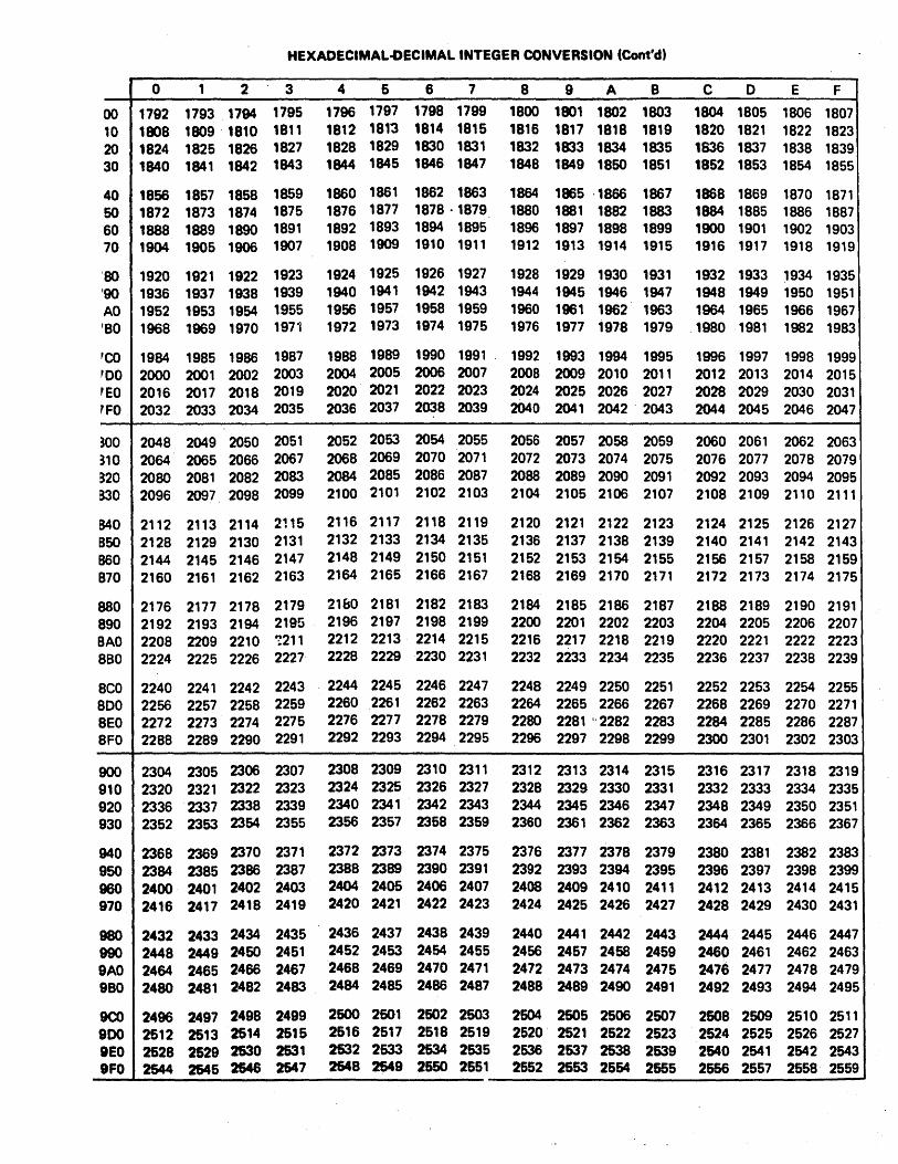
HEXADECIMAL.oECIMAL INTEGER CONVERSION (Cont'd)
0 1 2 3 4 6 6 7 8 9 A B C 0 E F
00 1792 1793 1794 1795 1796 1797 1798 1799 1800 1801 1802 1803 1804 1805 1806 1807 10 1808 1809 ·1810 1811 1812 1813 1814 1815 1816 1817 1818 1819 1820 1821 1822 1823 20 1824 1825 1826 1827 1828 1829 1830 1831 1832 1833 1834 1835 1836 1837 1838 1839 30 1840 1841 1842 1843 1844 1845 1846 1847 1848 1849 1850 1851 1852 1853 1854 1855
40 1856 1857 1858 1859 1860 1861 1862 1863 1864 1865 ·1866 1867 1868 1869 1870 1871 50 1872 1873 1874 1875 1876 1877 1878 ·1879 1880 1881 1882 1883 1884 1885 1886 1887 60 1888 1889 1890 1891 1892 1893 1894 1895 1896 1897 1898 1899 1900 1901 1902 1903 '10 1904 1905 1906 1907 1908 1909 1910 1911 1912 1913 1914 1915 1916 1917 1918 1919
'SO 1920 1921 1922 1923 1924 1925 1926 1927 1928 1929 1930 1931 1932 1933 1934 1935 '90 1936 1937 1938 1939 1940 1941 1942 1943 1944 1945 1946 1947 1948 1949 1950 1951 AO 1952 1953 1954 1955 1956 1957 1958 1959 1960 1961 1962 1963 1964 1965 1966 1967 'BO 1968 1969 1970 1971 1972 1973 1974 1975 1976 1977 1978 1979 .1980 1981 1982 1983
'CO 1984 1985 1986 1987 1988 1989 1990 1991 . 1992 1993 1994 1995 1996 1997 1998 1999 'DO 2000 2001 2002 2003 2004 2005 2006 2007 2008 2009 2010 2011 2012 2013 2014 2015 'EO 2016 2017 2018 2019 2020 2021 2022 2023 2024 2025 2026 2027 2028 2029 2030 2031 rFO 2032 2033 2034 2035 2036 2037 2038 2039 2040 2041 2042 2043 2044 2045 2046 2047
~OO 2048 2049 2050 2051 2052 2053 2054 2055 2056 2057 2058 2059 2060 2061 2062 2063 ~10 2064 2065 2066 2067 2068 2069 2070 2071 2072 2073 2074 2075 2076 2077 2078 2079 ~20 2080 2081 2082 2083 2084 2085 2086 2087 2088 2089 2090 2091 2092 2093 2094 2095 aJO 2096 2097 2098 2099 2100 2101 2102 2103 2104 2105 2106 2107 2108 2109 2110 2111
S40 2112 2113 2114 2',5 2116 2117 2118 2119 2120 2121 2122 2123 2124 2125 2126 2127 850 2128 2129 2130 2131 2132 2133 2134 2135 2136 2137 2138 2139 2140 2141 2142 2143 860 2144 2145 2146 2147 2148 2149 2150 2151 2152 2153 2154 2155 2156 2157 2158 2159 870 2160 2161 2162 2163 2164 2165 2166 2167 2168 2169 2170 2171 2172 2173 2174 2175
880 2176 2177 2178 2179 21&0 2181 2182 2183 2184 2185 2186 2.187 2188 2189 2190 2191 890 2192 2193 2194 2195 2196 2197 2198 2199 2200 2201 2202 2203 2204 2205 2206 2207 8AO 2208 2209 2210 '!211 2212 2213 2214 2215 2216 2217 2218 2219 2220 2221 2222 2223 8BO 2224 2225 2226 2227 2228 2229 2230 2231 2232 2233 2234 2235 2236 2237 2238 2239
8CO 2240 2241 2242 2243 2244 2245 2246 2247 2248 2249 2250 2251 2252 2253 2254 2255 800 2256 2257 2258 2259 2260 2261 2262 2263 2264 2265 2266 2267 2268 2269 2270 2271 8EO 2272 2273 2274 2275 2276 2277 2278 2279 2280 2281 "2282 2283 2284 2285 2286 2287 8FO 2288 2289 2290 2291 2292 2293 2294 2295 2296 2297 2298 2299 2300 2301 2302 2303
900 2304 2305 2306 2307 2308 2309 2310 2311 2312 2313 2314 2315 2316 2317 2318 2319 910 2320 2321 2322 2323 2324 2325 2326 2327 2328 2329 2330 2331 2332 2333 2334 2335 920 2336 2337 2338 2339 2340 2341 2342 2343 2344 2345 2346 2347 2348 2349 2350 2351 930 2352 2353 2354 2355 2356 2357 2358 2359 2360 2361 2362 2363 2364 2365 2366 2367
940 2368 2369 2370 2371 2372 2373 2374 2375 2376 2377 2378 2379 2380 2381 2382 2383 950 2384 2385 2386 2387 2388 2389 2390 2391 2392 2393 2394 2395 2396 2397 2398 2399 960 2400 2401 2402 2403 2404 2405 2406 2407 2408 2409 2410 2411 2412 2413 2414 2415 970 2416 2417 2418 2419 2420 2421 2422 2423 2424 2425 2426 2427 2428 2429 2430 2431
980 2432 2433 2434 2435 2436 2437 2438 2439 2440 2441 2442 2443 2444 2445 2446 2447 990 2448 2449 2460 2451 2452 2453 2454 2455 2456 2457 2458 2459 2460 2461 2462 2463 9AO 2464 2465 2466 2467 2468 2469 2470 2471 2472 2473 2474 2475 2478 2477 2478 2479 9BO 2480 2481 2482 2483 2484 2485 2486 2487 2488 2489 2490 2491 2492 2493 2494 2495
9CO 2496 2497 2498 2499 2500 2601 2502 2503 2604 2505 2506 2507 2508 2509 2510 2511 900 2512 2513 2514 2515 2516 2517 2518 2519 2520· 2521 2522 2523 2524 2525 2526 2527 BEO 2628 2629 2630 2531 2632 2533 2534 2535 2536 2637 2538 2539 2640 2541 2542 2543 BFO 2544 2645 2646 2647 2548 2649 2650 2651 2652 2653 2654 2665 2656 2557 2558· 2559

HEXADECIMAL-DECIMAL INTEGER CONVERSION (Cont'd)
0 ' 1 2 3 4 5 6 7 8 9 A B C 0 E F I Aoo 2660 2561 2662 2563 2564 2565 2566 2567 2568 2569 2570 2571 2572' 2573 2574 25751 Al0 2676 2577 2578 2579 2580 2581 2582 2583 2584 2585 2586 2587 2688 2589 2590 2591 A20 2592 2593 2594 2595 2596 2597 2598 2599 2800 2801 2602 2603 2604 2605 2606 2607 A30 2608 2609 ,2610 2611 2612 2613 2614 2615 2616 2617 2618 2619 2620 2621 2622 2623
MO 2624 2625 2626 ,2627 2628 2629 2830 2631 2832 2633 2634 2635 2636 2637 2638 2639 A50 2640 2641 2642 2643 2644 2645 2646 2647 2648 2649 2650 2651 2652 2653 2654 2655 A60 2656 2657 2658 2659 2660 2661 2662 2663 2664 2665 2666 2667 2668 2669 2670 2671 A70 2672 2673 2674 2675 2676 2677 2678 2679 2680 2681 2682 2683 2684 2685 2686 2687
A80 2688 2689 2690 2691 2692 2693 2694 2695 2696 2697 2698 2699 2700 2701 2702 2703 A90 2704 2705 2706 2707 2708 2709 2710 2711 2712 2713 2714 2715 2716 2717 2718 2719 AAO 2720 2721 2722 2723 2724 2725 2726 2727 2728 2729 2730 2731 2732 2733 2734 2735 ABO 2736 2737 2738 2739 2740 2741 2742 2743 2744 2745 2746 2747 2748 2749 2750 2751 .
ACO 2752 2753 2754 2755 2756 2757 2758 2759 2760 4761 2762 2763 2764 2765 2766 2767 ADO 2768 2769 2770 2771 2772 2773 2774 2775 2776 2777 2778 2779 2780 2781 2782 2783 AEO 2784 2785 2786 2787 2788 2789 2790 2791 2792 2793 2794 2795 2796 2797 2798 2799 AFO 2800 2801 2802 2803 2804 2805 2806 2807 2808 2809 2810 2811 2812 2813 2814 2815
BOO 2816 2817 2818 2819 2820 2821 2822 2823 2824 2825 2826 2827 2828 2829 2830 2831 Bl0 2832 2833 2834 2835 2836 2837 '2838 2839 2840 2841 2842 2843 2844 2845 2846 2847 B20 2848 2849 2850 3851 2852 2853 2854 2855 2856 2857 2858 2859 2860 2861 2862 2863 B30 2864 2865 2866 2867 2868 2869 2870 2871 2872 2873 2874 2875 2876 2877 2878 2879
B40 2880 2881 2882 2883 2884 2885 2866 2887 2888 2889 2890 2891 2892 2893 2894 2895 850 2896 2897 2898 2899 2900 2901 2902 2903 2904 2905 2906 2907 2908 2909 2910 2911 B60 2912 2913 2914 2915 2916 2917 2918 2919 2920 2921 2922 2923 2924 2925 2926 2927 B70 2928 2929 2930 2931 2932 2933 2934 2935 2936 2937 2938 2939 2940 2941 2942 2943
I B80 2944 2945 2946 2947 2948 2949 2950 2951 2952 2953 2954 2955 2956 2957 2958 2959 B90 2960 2961 2962 2963 2964 2965 2966 2967 2968 2969 2970 2971 2972 2973 2974 2975 BAO 2976 2977 2978 2979 2980 2981 2982 2983 2984 2985 2986 2987 2988 2989 2990 2991 B80 2992 2993 2994 2995 2996 2997 2998 2999 3000 3001 3002 3003 3004 3005 3006 3007
BCO 3008 3009 3010 3011 3012 3013 3014 3015 3016 3017 3018 3019 3020 3021 3022 3023 BOO 3024 3025 3026 3027 3028 3029 3030 3031 3032 3033 3034 3035 3036 3037 3038 3039 BEO 3040 3041 3042 3043 3044 3045 3046 3047 3048 3049 3050 3051 3052 3053 3054 3055 BFO 3056 3057 3058 3059 3060 3061 3062 3063 3064 3065 3066 3067 3068 3069 3070 3071
COO 3072 3073 3074 3075 3076 3077 3078 3079 3080 3081 3082 3083 3084 3085 3086 3087 Cl0 3088 3089 3090 3091 3092 3093 3094 3095 3096 3097 3098 3099 3100 3101 3102 3103 C20 3104 3105 3106 3107 3108 3109 3110 3111 3112 3113 3114 3115 3116 3117 3118 3119 C30 3120 3121 3122 3123 3124 3125 3126 3127 3128 3129 3130 3131 3132 3133 3134 3135
C40 3136 3137 3138 3139 3140 3141 3142 3143 3144 3145 3146 3147 3148 3149 3150 3151 C60 3152 3153 3154 3155 3156 3157 3158 3159 3160 3161 3162 3163 3164 3165 3166 3167 cao 3168 3169 3170 3171 3172 3173 3174 3175 3176 3177 3178 3179 3180 3181 3182 3183 C70 3184 3185 3186 3187 3188 3189 3190 3191 3192 3193 3194 3195 3196 3197 3198 3199
CSO. 3200 3201 3202 3203 3204 3205 ',3206 3207 3208 3209 3210 3211 3212 3213 3214 3215 C90 3216 3217 3218 3219 3220 3221 3222 3223 3224 3225 3226 3227 3228 3229 3230 3231 CAO 3232 3233 3234 3235 3236 3237 3238 3239 3240 3241 3242 3243 3244 3245 3246 3247 CBO 3248 3~49 3250 3251 3252 3253 3254' 3255 3256 3257 3258 3259 3260 3261 3262 3263 . CCO 3264 3265 3266 3267 3268 3269 3270 3271 3272 3273 3274 3275 3276 3277 3278 3279 COO 3280 3281 3282 3283 3284 3285 3286 3287 3288 3289 3290 3291 3292 3293 3294 3295 CEO 3296 3297 3298 3299 3300 3301 3302 3303 3304 3305 3306 3307 33Q8 3309 3310 3311 CFO ·3312 3313 3314 3315 3316 3317 3318 3319 3320 3321 3322 3323 3324 3325 3326 3327

HEXADECIMAL-DECIMAL INTEGER CONVERSION (Cont'd)
0 1 2 3 4 5 6 7 8 9 A B C 0 E F
)00 3328 3329 3330 3331 3332 3333 3334 3335 3336 3337 3338 3339 3340 3341 3342 3343 )10 3344 3345 3346 3347 3348 3349 3350 3351 3352 3353 3354 3355 3366 3357 3358 3359 )20 3360 3361 3362 3363 3364 3365 3366 3367 3368 3369 3370 3371 3372 3373 3374 3375 )30 3376 3377 3378 3379 3380 3381 3382 3383 3384 3385 3386 3387 3388 3389 3390 3391
)40 3392 3393 3394 3395 3396 3397 3398 3399 3400 3401 3402 3403 3404 3405 3406 3407 )50 3408 3409 3410 3411 3412 3413 3414 3415 3416 3417 3418 3419 3420 3421 3422 3423 )60 3424 3425 3426 3427 3428 3429 3430 3431 3432 3433 3434 3435 3436 3437 3438 3439 )70 3440 3441 3442 3443 3444 3445 3446 3447 .. 3448 3449 3450 3451 3452 3453 3454 3455
)80 3456 3457 3458 3459 3460 3461 3462 3463 3464 3465 3466 3467 3468 3469 3470 3471 )90 3472 3473 3474 3475 3476 3477 3478 3479 3480 3481 3482 3483 3484 3485 3486 3487 )AO 3488 3489 3490 3491 3492 3493 3494 3495 3496 3497 3498 3499 3500 3501 3502 3503 )BO 3504 3505 3506 3507 3508 3509 3610 3511 3612 3613 3514 3515 3516 3517 3518 3519
)CO 3520 3521 3522 3523 3524 3525 3526 3527 3528 3529 3530 3531 3532 3533 3534 3535 :CO 3536 3537 3538 3539 3540 3541 3542 3543 3544 3545 3546 3547 3548 3549 3550 3551 )EO 3552 3653 3554 3555 3656 3557 3558 3559 3560 3561 3562 3563 3564 3565 3566 3567 )FO 3568 3569 3570 3571 3572 3573 3574 3575 3576 3577 3578 3679 3580 3581 3582· 3583
Eoo 3584 3585 3586 3587 3588 3589 3590 3591 3592 3593 3594 3595 3596 3597 3598 3599 E10 3600 3601 3602 3603 3604 3605 3606 3607 3608 3609 3610 3611 3612 3613 3614 3615 :20 3616 3617 3618 3619 3620 3621 3622 3623 3624. 3625 3626 3627 3628 3629 3630 3631 E30 3632 3633 3634 3635 3636 3637 3638 3639 3640 3641 3642 3643 3644 3645 3646 3647
E40 3648 3649 3650 3651 3652 3653 3654 3655 3656 3657 3658 3659 3660 3661 3662 3663 E50 3664 3665 3666 3667 3668 3669 3670 3671 3672 3673 3674 3675 3676 3677 3678 3679 E60 3680 3681 3682 3683 3684 3685 3686 3687 3688 3689 3690 3691 3692 3693 3694 3695 E70 3696 3697 3698 3699 3700 3701 3702 3703 3704 3705 3706 3707 3708 3709 3710 3711
ESO 3712 3713 3714 3715 3716 3717 3718 3719 3720 3721 3722 3723 3724 3725 3726 3727 Ego , 3728 3729 3730 3731 3732 3733 3734 3735 3736 3737 3738 3739 3740 3741 3742 3743 EAO 3744 3745 3746 3747 3748 3749 3750 3751 3752 3753 3754 3755 3756 3757 3758 3759 EBO 3760 3761 3762 3763 3764 3765 3766 3767 3768 3769 3770 3771 3772 3773 3774 3775
ECO 3776 3777 3778 3779 3780 3781 3782 3783 3784 3785 3786 3787 3.788 3789 3790 3791 EDO 3792 3793 3794 3795 3796 3797 3798 3799 3800. 3801 3802 3803 3804 3805 3806 3807 EEO 3808 3809 3810 3811 3812 3813 3814 3815 3816 3817 3818 3819 3820 3821 3822 3823 EFO 3824 3825 3826 3827 3828 3829 3830 3831 3832 3833 3834 3836 3836 3837 3838 3839
FOO 3840 3841 3842 3843 3844 3845 3846 3847 3848 3849 3850 3851 3852 3853 3854 3855 F10 3856 3857 3858 3859 3860 3861 3862 3863 3864 3865 3866 3867 3868 3869 3870 3871 F20 3872 3873 3874 3875 3876 3877 3878 3879 3880 3881 3882 3883 3884 3885 3886 3887 F30 3888 3889 3890 3891 3892 3893 3894 3895 3896 3897 3898 3899 3900 3901 3902 3903
F40 3904 3905 3906 3907 3908 3909 3910 3911 3912 3913 3914 3915 3916 3917 3918 3919 F50 3920 3921 3922 3923 3924 3925 3926 3927 3928 3929 3930 3931 3932 3933 3934 3935 F60 3936 3937 3938 3939 3940 3941 3942 3943 3944 3945 3946 3947 3948 3949 3950 3951 F70 3952 3953 3954 3955 3956 3957 3958 3959 3960 3961 3962 3963 3964 3965 3966 3967
FSO 3968 3969 3970 3971 3972 3973 3974 3975 3976 3977 3978 3979 3980 3981 3982 3983 F90 3984 3985 3986 3987 3988 3989 3990 3991 3992 3993 3994 3995 3996 3997 3998 3999 FAO 4000 4001 4002 4003 4004 4005 4006 4007 4008 4009 4010 4011 4012 4013 4014 4015 FBO 4016 4017 4018 4019 4020 4021 4022 4023 4024 4025 4026 4027 4028 4029 4030 4031
FCC 4032 4033 4034 4035 4036 4037 4038 4039 4040 4041 4042 4043 4044 4045 4046 4047 FDD 4048 4049 4050 4051 4052 4053 4054 4055 4056 4057 4058 4059 4060 4061 4062 4063 FEO 4064 4065 4066 4067 4068 4069 4070 4071 4072 4073 4074 4075 4076 4077 4078 4079 FFO 4080 4081 4082 4083 4084 4085 4086 4087 4088 4089 4090 4091 4092 4093 4094 4095

SIMULATOR INSTALLATION NOTES
These notes are designed to help the user install the Simulator
and perform any modifications that may be necessary for a particular
computer. The Notes are sep~rated into six sections: Program
Installation, Program MOdifications, Batch/Interactive Mode, Program
Input/Output, Memory Requirements and Overlays, and NOVA MOdifications.
A. Program Installation .
1. The Simulator should be compiled once and its object module
stored on some secondary storage device (disk). Compile the
program in the usual manner, assigning it a name which can be
refered to by an Execute or Run Statement. It is usually
helpful to compile each subroutine separately. If upon loading
the compiled program, it is discovered that not enough main
memory is available to hold the entire program, refer to the
section describing overlay structures.
B. Program M~difications
1. Some computers do not accept the full ASCII character set.
Therefore, some of the characters defined in Subroutine INIT may
be illegal and give a compilation error. If this is the case
on your computer, the illegal characters must be replaced by
legal characters. The characters are in the Array NALPH. If
the illegal character is not used in the simulator as an operator,
terminator, or a character in a symbol, replace the illegal
character with a zero, O. The illegal character may not be used
between quote marks to represent an ASCII character constant.
If the illegal character is used by the Simulator, replace the
character with a unique legal character and use the new character
in place of the old, illegal character. Note: some computers
will not accept certain characters during a Fortran compilation,
but will accept the characters as program input data.
In this case t the user could define the problem characters
as numbers instead of hollerith constants. The numbers used
would be the internal values of the characters as they would
appear in a lH data specification. An example of characters
defined in this manner is shown in the NOVA modifications.
2. The variable IBIT corresponds to the number of bits per word
in the host computer. IBIT is initially set to 16. This variable
determines how many characters are packed into one host computer
word for symbols stored in the Simulator symbol table. The user
may want to increase this variable if the computer has a longer
word length. However t it is not necessary. Increasing IBIT will
allow a larger number of symbols to be stored in a fixed amount of
memory. When initially installing the programt it is suggested
that IBIT be left at 16 until the program is known.to be.operat~ng
correctly.
3.: To increase the size of the symbol table and thus the number
and length of the symbols the symbol table can hold t the user must
change certain variables. The variables that must be changed
depend on the number of bits per host computer word (see 2)t the
number of symbols in the symbol tablet and the number of characters
used to define a symbol. The variables· that define these parameters
are described below.
IBIT - number of bits per host computer word (set by user)
MLAB - maximum label length in characters (set by user)
ICCNT - number of characters per host computer word (calculated)
IWORD -number of computer words per symbol (calculated)
LTAB - length of symbol table (set by user)
The user must change the following variables to reflect the size
of the symbol table and length of a symbol. The length of a
symbol should probably correspond to the length set in the Assembler

if symbols are passed from the assembler. The arrays are in
COMMON, and therefore, the dimensions need to be changed in
every subroutine and the main program.
I TAB (IWORD,LTAB)
ITAV(LTAB)
NAME (IWORD) .
where: !WORD = l+(MLAB-l)/ICCNT
ICCNT = IBIT/8
4. The Simulator uses a random access disk file to simulate
the full 65536 bytes of mdcroprocessor memory. The memory sections
or pages most recently accessed by the simulated program are
swapped into a main me~ory array. This procedure minimizes the
memory requirements of the simulator on the host computer. A
mUlti-page scheme keeps page swapping to a minimum. Several other
things have been done to minimize page swapping and keep program
execution speed high. Memory pages are initialized only when they
are accessed. If they are never accessed, they are never initial
ized. If the data on a page is not changed, the page is not re
written to the disk file since this is not necessary and would only
slow the program down.
If the user wishes to, he may increase or decrease the memory
page size and the record length of the simulated memory disk file.
If desired, the whole simulated memory may be implemented in main
memory, eliminating the intermediate disk file altogether. If the
user does perform any of these modifications, he must be aware of
the following key variables.
MXMEM - maximum memory size stmulated (initially set to 65536, set by user)
MEM - array used to hold simulated pages in main memory (initially set to 1536, set by user to 3*MSIZE)
MSIZE - length of memory page (initially set to 5l2,set by user)
IRLEN - length of simulated memory disk file record in words (initially set to 128, set by user)
INUM - number of disk records per memory page (initially 4, calculated variable, INUM = MSIZE/IRLEN)
KPAGE - array indicating whether a page has been accessed (initially set to 128, set by user to 65536/MSIZE)

Because the disk physical record size for some computers_.is
limited. each disk read or write transfers only 128 words of
simulated memory. Therefore. when a 512 byte page is swapp~d,
4 disk transfers take place. If larger records can be handled
on the user's computer, disk activity can be minimized (and
execution time reduced) by increasing the number of words per
disk read and write. The record length should be a power of
two and evenly divisible into the page size. If possible,
increase the IRLEN variable to the page size, MSIZE.
The user should. carefully' consider the~. ma~er before increasing
or decreasing the page size of the:s:1mulated memory. Increasing
the page size may speed the simulator up, it could also slow it
down. Likewise, decreasing the page size may also affect the
speed in either direction. What happens to execution time when
the page size changes depends on the program being simulated. If
the user only simulates programs of lK words in length and the
data page is 256 bytes, then a page size of 512 words is perfect.
Larger pages are not' needed, and smaller pages would only increase
disk activity. If the user simulates programs that jump back and
forth allover memory, and access data at different locations,
a smaller page size would speed up the program. A smaller page
means that less data needs to be read from and written to the disk
~en p~ges are swapped.
If the user wishes· to implement· the whole simulated memory
in main memory, he can by increasing the dimension of the array
MEM to 65536. The page size should be set to 21512. With these
variables set to the values indicated, the disk will never be
referenced. It should be noted that array dimensions oannot
usually exceed 32767 on mo~t 16 bit machines. Another option
the user has in eliminating the disk file, is to set the MEM
array to a value less than 65536 and set the variable MXMEM to
this dimension. Whenever an address exceeds the MXMEM value,
an error message will be displayed.

5. The user may want to modify the standard' display line associated
with the "FORM S" command in order to display additional registers
and status bits. This can be done by modifying the short display
line ~ite statement and its associated format statement. The
variables of interest are listed below along with the Format by
which t~ey should be written to the output listing. The Write
and Format statements are in Subroutine DISPL and are marked by
comments.
Instruction Address 4AI (IADDR(3,I),I=I,4)
Next Instruction Address 4AI (IADDR(2,I),I=I,4)
Instruction Mnemonic 2A2 MNEI(ITYPE), MNE2(ITYPE)
Instruction Operand 10Al (NOUT(I), 1=1,10)
A Register 2Al IROUl(8), IROU2(8)
B Register 2Al IROUl(l) , IROU2(1)
C Register 2Al IROUl(2), IROU2(2)
D Register 2AI IROUI(3), IROU2(3)
E Register 2AI IROUI(4), IROU2(4)
H Register 2Al IROUI(5), IROU2(5)
L Register 2Al IROUl(6), IROU2(6)
Stack Fointer 4AI (IADDR(I,I),I=I,4)
Cycle Count 4Al (ICOUT(I),I=I,4)
Zero Flag Al FFO(I)
Carry Flag Al FFO(2)
Parity Flag Al FFO(3)
Sign Flag Al FFO(4)
Interdigit Carry AI. FFO(5)
Effective (Operand) Address 4AI (IADDR(4,I),I=I,4)
Effective Address Contents 2AI lEAI,IEA2
6. The Simulator can recognize tab characters as field
delimiters. but the uer must initialize the tab character in
Subroutine INIT. Currently the tab character. NCTAB. is
initialized to a blank in a DATA statement. The value that
NCTAB.must be initialized to varies from machine to
machine. On many computers it is possible to encode the tab
value as lH(tab) in the DATA statement. If this is not possible
on your machine, then the tab character will have to be init
ialized as a number. For most 16 bit ASCII machines this would
be. NCTAB = 9*256+32. 9 is the ASCII value for a tab; 32 is
the ASCII value for a blank. For PDP-lls, the bytes are switched,
so NCTAB = 32*256+9. Most versions of NOVA Fortran do not have
the trailing blank included so NCTAB = 9*256. Machines with
word lengths greater than 16 bits must pad out the tab character
value with as many blnaks as are in a host's word. Initializing
a tab character will allow the Simulator to properly process an
input source line that includes tabs. However~ the Simulator
does not expand the output line with tabs replaced by blanks.
This must be done by the computer's operating system.

C. Batch/Interactive Mode
1. The program is delivered with the Batch/Interactive flag, IBAT,
set to the interactive mode. In the Interactive mode, commands are
not echoed to the listing device and errors do not cause program
termination. In the Batch mode, commands are echoed to the
listing device, all command errors cause program termination.
and the command prompt is not displayed. Also in the Batch mode,
messages'are not displayed asking for input data. The user must
determine the input data before executing the program and include
it in the command stream.
D. Program Input/Output
1. The logical I/O device assignments made in the Simulator
for the "Standard I/O Devices" are:
IRDR = 7 (object module input
IMFLE = 18 (intermediate file)
Batch I/O
ICRD = 5 (command, input device)
IPRT = 6 (output listing device)
Interactive I/O
ITERC = 1 (command input device)
ITERP = 1 (output listing device)
device)
These device assignments may have to be changed for your computer.
This may be done either in t'he Job Control Stream that executes
the Simulator or in the Program itself 'at compile time. If the
a~signments need to be changed in the program, the statements
initializing 'the variables may be found in Subroutine INIT.
Typically, the user only needs to change the Batch or Interactive
assignments, since he will only be using the Simulator in one
of these modes. Note that in the interactive mode both the input
command device and the output listing device have the same device
number. This is the usual case since they are typcially the same
device.

2. When I/O is performed with a file, a logical device number
is equated to the specified file so the file can be read from
or written to by the I/O statements in Subroutine INOUT. The
logical device numbers used for the various file types are
shown below. After the file-logical dev.ice equating has been
performed in Subroutine EQUAT, the file's logical device number
is placed in a variable that represents the actual active input
or output device. These are: IOCRO - command input device,
IOPRT - output listing device, and IORDR - object module input
device.
IFILC = 8 (command input logical device number which is equated to a file name)
IFILP = 9 (listing output logical device number which is equated to a file name)
IFILR = 10 (object module input logical device number which is equated to a file name)
It may be necessary to change these device assignments on your
computer. The variables should be set to device numbers that
can be equa~ed with disk files.
3. The Simulator's intermediate file is a temporary file that
is used to contain the microprocessor's simulated memory. This
file must be random access. Some systems require disk space to
be allocated for this temporary file in the Job Control Stream.
Check to see if this is necessary for your computer. The
Intermediate file is represented by the logical device number,
IMFLE.
4. All Program I/O activity except for the generation of the
output listing is handled in Subroutine INOUT. This includes
displaying command prompts, reading the command input, and
reading the input object module. Also included in INOUT is
the display statements used for the SM, SIN, and SOUT commands.
This display only occurs if the commands are continued on
additional lines.

5. Reading and writing to a bulk storage device such as a'disk
is not standard in Fortran. There are however, two usual methods
of performing these operations. Method 1 uses a DEFINE FILE
statement and standard Read and Write statements as follows:
DEFINE FILEIMFLE(513,128,U,IMREC)
WRITE(~MFLE'IMREC) LIST
READ (IMFLE'IMREC) LIST
where: IMFLE - is the logical device number of the file
513 - is the maximum number of records in the file
128 - ,is the record length in words
U - indicates a binary record
IMREC - indicates the record number (associated variable)
LIST - list of variables to read or write
Method 2 uses a CALL to an executive or system routine to process
the disk read or write. For a typical computer this call is:
CALL EXEC (#,CODE,IBUF,CNT,NAME,IMREC)
where: # indicates the type of call, read or write
CODE - indicates binary or formatted I/O, etc. 7
IBUF - starting address of variables to read or write
NAME - is typcia11y a dimensioned array which contains the name of the disk file. This name is then used in the Job Control Stream to allocate the file.
IMREC - disk record number
The Simulator uses Method 1 as the standard method. However,
statements for Method 2 are included in the program as 'comment
statements for reference.

6. There are alternate ways of reading object modules and
command files into the Simulator. They may be read from an
I/O device (card reader, etc.) that can be refered to by a
logical device number, or they may be read from disk files.
If they are read from I/O devices that can be refered to by
a logical device number. the number is used as the argument
on the appropriate command. If the commands or object modules
exist as disk files, the file name should be specified ~s the
command argument. Subroutine EQUAT is used to equate a disk
file and a logical device number so that the file may be read
by the statements in Subroutine INOUT. The file logical device
assignments for the various input ,and output devices are listed
in 2. There are two basic parts to the EQUAT Subroutine. First,
the file name is packed inot'.a contiguous Hollerith string.
The code used to pack the characters into a string will work on
any two's complement machine. For a one's complement machine,
one line of code must be changed. The required change is marked
with comments in Subroutine EQUAT. EQUAT also forms another array,
IPBUF, ~hich contains the file name in an A1 format, only one
character per word. If the user must use the packed form of the
file name to perform the acutal equate, two variables in
Subroutine INIT must be set to the correct values for EQUAT to
work properly. These are:
ISBIT - actual number of bits in host, computer word. This mayor may not be the same an IBIT.
ICHBT ~ number of· bits per host computer character.
The place in INlT where these variables are set is marked with
comments.
The second part of Subroutine EQUAT consists of the code required
to open the named disk file and equate it to a logical device
number. This code usually consists of one statement. Some
computers can read disk files without any special code to open
the file. In this case, Subroutine EQUAT may not be needed,

or only needed to pack the file name into a contigious hollerith
string. The array name, NAMEF, would then be 'placed in the file
Read and Hrite statements in Subroutine INOUT. The user will
have to check his computer manuals to find out what the required
statements are to perform the file name and logical device
number equate.
7. The I/O statements needed to read object modules and commands
from disk files are usually the same as those that read from
logical devices. However, they may be different and statements
in INOUT provide for this case. The statements at 250 and
·350 r~ad Commands and Object modules from disk files. These
statements are currently the same as those at 200 and 300 which
read from logical devices. If the user must change the statements
at 250 and 350, he can.
8. Statements are included in Subroutine INOUT for handling an
End-Of-File (EOF) condition on both the command and object module
input devices. The READ statements with the END condition speci
fied, as shown in INOUT, can be used on most machines to detect an
EOF. However, some systems require a call to a system routine or
some other statement to detect an EOF •. Comments in Subroutine
INOUT are included to show where the program should branch when
anEOF is detected. The user may not use the EOF feature to trace
one instruction (see page 3-53) if an EOF cannot be detected.
No modifications need to be made to the INOUT routine if EOFs
cannot be detected. If the EOF conditions are not detected,
the user should expect to get a system error if he does read
through the end of a file.

9. In the Interactive mode, the program will display a prompt
character (~) to request the next.command from the user. If the
user's system already displays a prompt for input data, the user
may wish to remove the code that generates the Simulator's prompt.
This code is located in Subroutine INOUT at Fortran statement
number 100. When t;he prompt· is displayed, 1l~ers-:."\41tl piobably" not-
want the terminal to advance to the next line to read the command.
Most systems have a format control that allows a line to be dis-·
played on the terminal with no carriage return generated ·~at the
end of the line. For a NOVA, using the Z format is sufficient to
prevent the carriage return. Thus, the format statement in
Subroutine INOUT would be:
1000 FORMAT(lH-,Z)
For a PDP-11 the format statement would be:
1000 FORMAT(lH-,$)
10. The user may also want to inhibit a carriage return in the
interactive mode when the SM, SIN, or SOUT commands are continued
on ad~itiona1 lines. The statements displaying the address being
modified for these commands are at Fortran statement number 400
in Subroutine INOUT. To prevent the carriage return from being
generated for these commands Format.statement 1003 should be
modified in the manner described in 9.
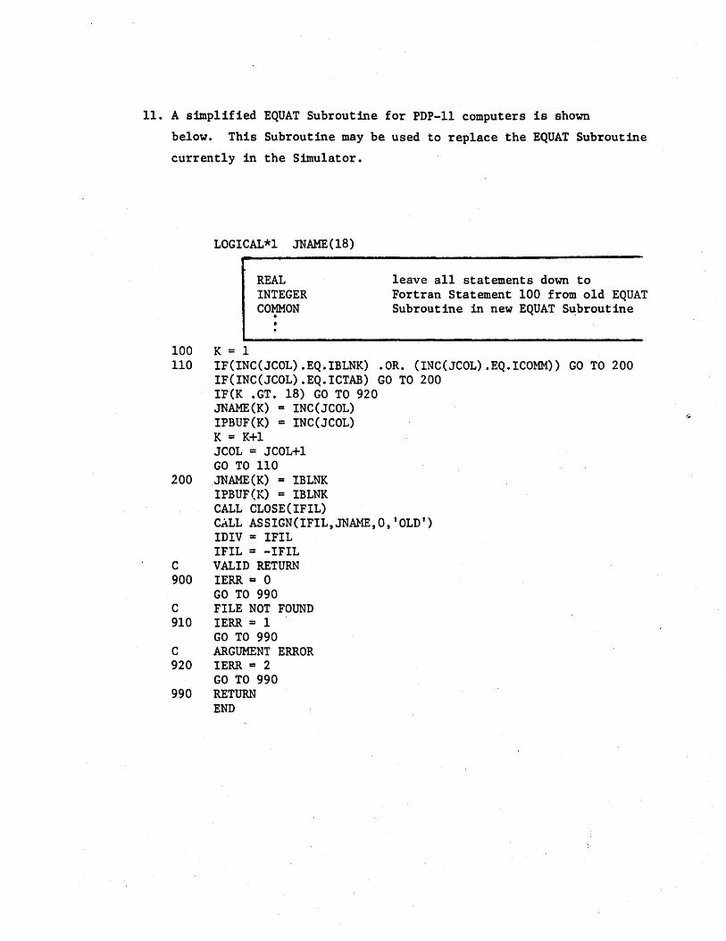
11. A sfmp1ified EQUAT Subroutine for PDP-1l computers is shown
below. This Subroutine may be used to replace the EQUAT Subroutine
currently in the Simulator.
LOGICAL*l JNAME(18)
100 K = 1
REAL INTEGER COMMON .
leave all statements down to Fortran Statement 100 from old EQUAT Subroutine in new EQUAT S~broutine
110 IF(INC(JCOL).EQ.IBLNK) .OR. (INC(JCOL).EQ.ICOMM» GO TO 200 IF(INC(JCOL).EQ.ICTAB) GO TO 200 IF(K .GT. 18) GO TO 920 JNAME(K) = INC(JCOL) IPBUF(K) = INC(JCOL) K = K+1 JCOL = JCOL+1 GO TO 110
200 JNAME(K) = IBLNK IPBUF(K) = IBLNK CALL CLOSE(IFIL) CALL ASSIGN(IFIL,JNAME,O,'OLD') IDIV = IFIL IFIL = -IFIL
C VALID RETURN 900 IERR 1:1 0
GO TO 990 C FILE NOT FOUND 910 IERR = 1
GO TO 990 C ARGUMENT ERROR 920 IERR 1:1 2
GO TO 990 990 RETURN
END

E. Memory Requirements and Overlays
1. If core size is limited, the Simulator program may have to
be overlayed. One overlay structure is shown below. This I
overlay structure will have minimal effect on program speed.
Main
MAIN INOUT COMMD SIMU DISPL LABEL SYMBL SCAN MEMRW IORW AVHEX
1st Overlay
INIT
2nd Overlay
SIMU FUNC
3rd Overlay
LOAD8 EQUAT MESS
If necessary, additional routines can be placed in the 3rd Overlay.
However, program speed may be noticeably affected.
2. To aid those users who need to form their own Overlays or
to Segment their programs, the following list shows each
routine in the 'Simulator and all the routines that call it.
MAIN -INIT INOUT - COMMD,LOAD8,MEMRW,IORW COMMD - MAIN SIMU COMMD DISPL - COMMD LOAD8 - COMMD LABEL - COMMD,SCAN SYMB L - LOAD8, LAB EL SCAN - COMMD,LOADB,IORW,EQUAT MEMRW - COMMD,SIMU,DISPL,LOAD8 IORW - SIMU,MEMRW FUNC - SIMU AVHEX - COMMD,DISPL,IORW EQUAT - COMMD MESS - COMMD,LOAD8,IORW
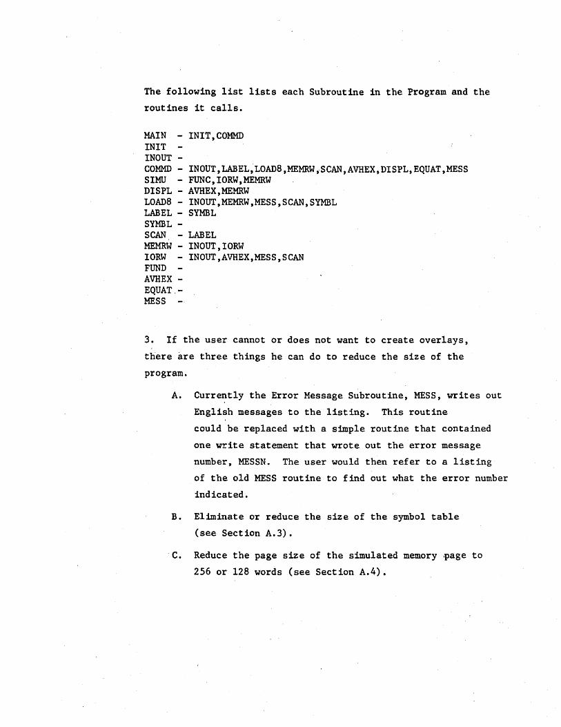
The following list lists each Subroutine in the Program and the
routines it calls.
MAIN - INIT,COMMD INIT INOUT -COMMD - IN OUT ,LABEL,LOAD8 ,MEMRW ,SCAN, AVHEX, DISPL, EQUAT ,MESS SIMU - FUNC, IORW,MEMRW DISPL - AVHEX,MEMRW LOAD8 - IN OUT ,MEMRW ,MESS, SCAN ,SYMBL LABEL - SYMBL SYMBL -SCAN. - LABEL MEMRW - INOUT, IORW IORW - INOUT ,AVHEX,MESS, SCAN FUND AVHEX -EQUAT.-MESS
3. If the user cannot or does not want to create overlays,
there are three things he can do to reduce the size of the
program.
A. Currently the Error Message Subroutine, MESS, writes out
English messages to the listing. This routine
could be replaced with a simple routine that contained
one write statement that wrote out the error message
number, MESSN. The user would then refer to a listing
of the old MESS routine to find out what the error number
indicated.
B. Eliminate or reduce the size of the symbol table
(see Section A.3).
c. Reduce the page size of the simulated memory .page to
256 or 128 words (see Section A.4).

F. NOVA Modifications
When installing the Simulator on a NOVA Computer, it is suggested
that Fortran V be used. If Fortran IV is used, some additional
program modifications have to be made.
1. Most versions of NOVA Fortran fill an H data specification
statement with zeros and not b1ank~t as is typcia11y done.
Therefore, characters read in under A formats must have the padded
blanks stripped off so they will match equivalent characters, stored
in the program under H formats. Insert the following statements
after Fortran,statement 380 in INOUT.
DO 382 1=1,80 IN(I) = IN(I).AND-256
382 CONTINUE·
2. All variables initialized in DATA statements must be placed
in Labeled COMMON. The variables are local to each Subroutine,
so unique dummy labels may be used for the COMMON Block names.
3. The DEFINE FILE Statement in the Main Program must be replaced
with a CALL OPEN statement similar to the one shown below.
CALL OPEN(IMFLE,"IDUMl",3,IER,256)
4. The Simulator intermediate file must be a random access file,
so a Callto FSEEK must preceed each file access. Use Binary Read
and Write statements for the intemediate file. To implement this,
change the Fortran source code in INOUT ap follows:
CALL FSEEK (IMFLE,IMREC) IF(ICTL .EQ. 7) GO TO 630 READ BINARY (IMFLE) (MEM(I),I=Il,I2) GO TO 640
630 WRITE BINARY (IMFLE) (MEM(I),I=Il,I2) 640 II + 12+1

5. Several characters cannot be used in Hollerith Data Specifi
cations since they are not in the NOVA assembler's legal character
set. These include right and left parenthesis, percent sign,
quote mark, etc. Check your Assembly Language Manual for the
legal character set. In Subroutine INIT replace all illegal
characters in the array NALPH with their internal representations
as they would appear in a lH Data format.
DATA NALPH(37),NALPH(38),NALPH(39),NALPH(40) /16l28,lH@,lH ,1H!/
DATA NALPH(4l),NALPH(42),NALPH(43),NALPH(44) /8704,lH#,92l6,9472/
DATA NALPH(45),NALPH(46),NALPH(47),NALPH(48) /lH&,9984,10240,10496/
DATA NALPH(57),NALPH(58),NALPH(59) /15360,lH=,l5872/