microwave device and physical … 26 4 1 microwave device and physical electronics laboratory...
TRANSCRIPT
72- 26 4 1
MICROWAVE DEVICE AND PHYSICALELECTRONICS LABORATORYDEPARTMENT OF ELECTRICAL ENGINEERING
U N I V E R S I T Y OF UTAHSALT LAKE CITY, UTAH 84112
https://ntrs.nasa.gov/search.jsp?R=19720018769 2018-07-06T21:35:16+00:00Z

University of Utah UTEC MD 71-061
Research Committee
AMPLITUDE AND POLARIZATION ASYMMETRIES
IN A RING LASER
by
L. L. Campbell and N. E. Buholz
Technical Report RC-1
January 1971
Microwave Device and Physical Electronics LaboratoryElectrical Engineering Department
University of UtahSalt Lake City, Utah
ABSTRACT
Asymmetric amplitude effects between the oppositely directed
traveling waves in a He-Ne ring laser are analyzed both theoretically
and experimentally. These effects make it possible to detect angular
orientations of an inner-cavity bar with respect to the plane of the
ring cavity. The amplitude asymmetries occur when a birefringent bar
is placed in the three-mirror ring cavity, and an axial magnetic field
is applied to the active medium.
The theoretical problem is complicated by the presence of axial
magnetic field effects in the active medium, anisotropic loss result-
ing from the Brewster windows, and linear birefringence exhibited by
the quartz bar. A simplified theoretical analysis is performed by us-
ing a first order perturbation theory to derive an expression for the
polarization of the active medium,•'.and a set of self-consistent equa-
tions are derived to predict threshold conditions. It is determined
that the amplitude asymmetries are caused by the axial magnetic field
effects in the active medium and the linear birefringence of the bar.
Polarization asymmetries between the oppositely directed waves are
also predicted. The amplitude and polarization asymmetries are only
predicted to occur in cavities formed by an odd number of mirrors (in
this case, three).
Amplitude asymmetries similar in nature to those predicted at
threshold occur when the laser is operating in 12-15 free-running
modes. These asymmetries also exist at power levels near threshold.
- ix -
The polarization asymmetry occurs simultaneously with the amplitude
asymmetries. Both amplitude and polarization asymmetries cease to
exist in a four-mirror cavity. Asymmetric polarization changes are
shown to occur between oppositely directed waves when light on a
single-pass propagates through the combination of an active medium
in the presence of an axial magnetic field and a birefringent bar in
a three-mirror cavity.
The percent increase or decrease in the intensity of the oppo-
sitely directed waves is found to be approximately linear for small
rotations of the quartz bar, thus making it easy to determine the
angular orientation of the bar by monitoring the magnitude and sign
of the oppositely directed wave intensities.
- iii -

ACKNOWLEDGMENT
The authors express their appreciation to the Research
Committee of the University of Utah for their support of the
research project described in this report, and to the National
Aeronautics and Space Administration for Mr. Campbell's Graduate
Fellowship.
- iv -
TABLE OF CONTENTS
ABSTRACT ii
ACKNOWLEDGMENT iv
LIST OF ILLUSTRATIONS AND TABLES . vi
PREFACE vii
I. THEORY OF THE RING LASER
1.1. Introduction 1
1.2. Circuit Equations 2
1.3. Polarization of the Medium 9
1.4. Self-Consistent Equations
1.4.1. General Self-Consistent Equations 18
1.4.2. Amplitude Equations 19
1.4.3. Reactive Balance Conditions 22
1.4.4. The a' and x Terms 25
1.5. Discussion 27
II. EXPERIMENTAL RESULTS
2.1. Introduction 34
2.2. Experimental Apparatus 35
2.3. Bidirectional Operation 37
2.4. Asymmetric Amplitude and Polarization Changes 39
2.5. Related Experiments 44
2.6. Rotations About the Longitudinal and Normal Axes ... 50
III. CONCLUSIONS 55
- v —

LIST OF ILLUSTRATIONS AND TABLES
Figure Page
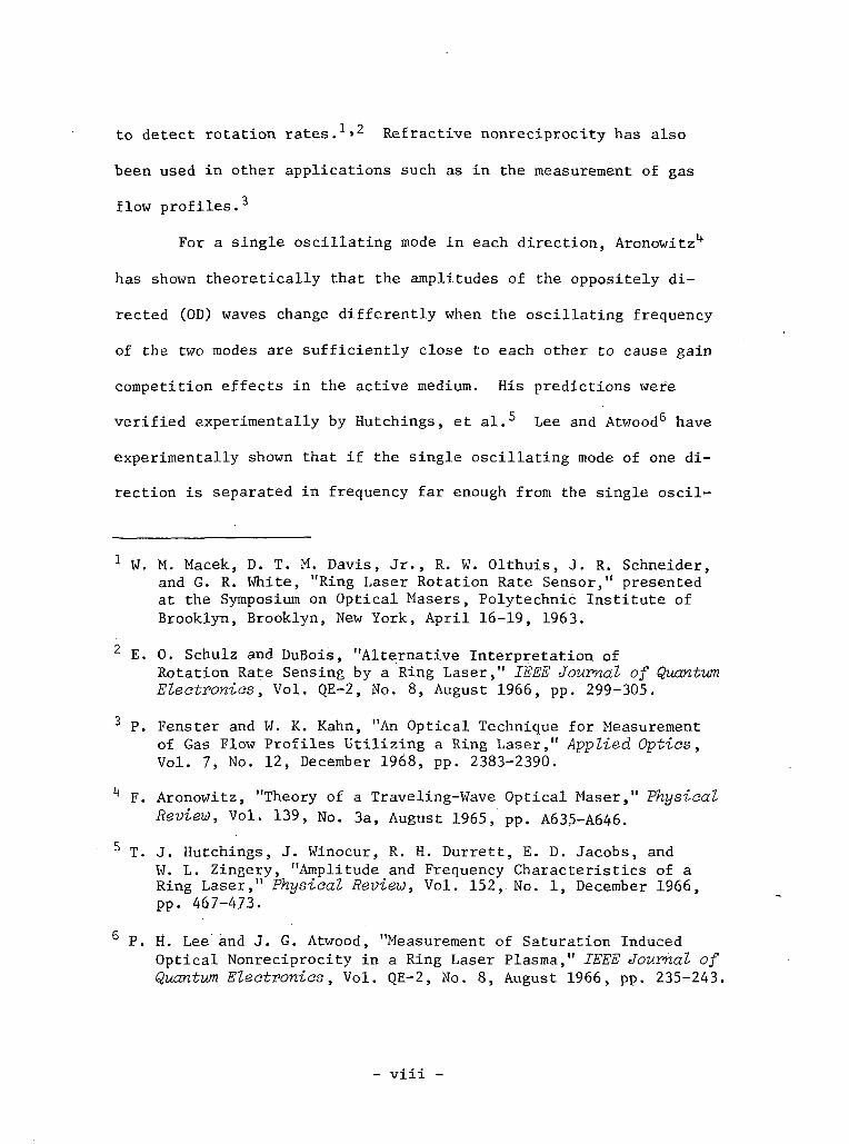
1 Ring laser schematic x
2a Schematic diagram of the ring laser showing the positionof the electromagnets and the quartz bar. The polariza-tion of the OD waves is measured from the output ofmirror No. 3, while their amplitudes are measured fromthe output of mirror No. 2.: R = 6 m, 3m, and infinityfor mirrors Nos. 1, 2 and 3, respectively 36
2b Picture of the ring laser 36
3a Schematic diagram of the quartz bar showing the threeaxes; the bar's c-axis is aligned along the transverseaxis 38
3b Enlarged view of the bar 38
4 Percent increase and decrease in the intensity of the ODwaves for various values of a, that is, for various barorientations about the transverse axis when the differ-ential field of 160 gauss is applied. The straight linesare least square fits to data (taken at position of max-imum sensitivity) 41
5 Experimental arrangement used to determine the polariza-tion rotation characteristics of light passing throughthe quartz bar as the bar is rotated about the transverseaxis (see Fig. 3):
a. In a three mirror arrangementb. In a four mirror arrangement 47
6 Sensitivity (percent intensity change/degree rotationabout the transverse axis) for various bar orientationsabout the longitudinal axis 51
7 Shift in the position of the asymmetric null as the bar'sc-axis is rotated about the normal axis out of the nullplane. The straight line is a least square fit to thedata 54
Table
Determination of phase angle \p between the x and y fieldcomponents for a balanced magnetic field 43
- vi -

PREFACE
A ring laser is a device in which the mirrors forming the
laser cavity are placed at the corners of a polygon. Active material
is placed along one or more sides of the polygon. Laser action
occurs for waves which are resonant in the polygon and which have
sufficient gain in the active medium. Such waves have a gain equal
loss condition around the ring and continue to circulate indefi-
nitely.
The important difference between ring lasers and other lasers
is that the normal modes of the ring are traveling waves rather than
standing waves. Hence, it is possible to obtain two waves traveling
in opposite directions around the ring which do not have the same
amplitude or frequency even though* they are associated with the samer»-: *
resonant frequency of the polygon, -The two amplitudes differ if the
waves see different gain or loss as they traverse the ring perimeter,
and the two frequencies differ if the optical path length is differ-
ent in the two directions. Thus the ring laser provides a means by
which phenomena that result in either a gain/loss or refractive non-
reciprocity may be studied and utilized.
Most attention has been directed toward studies involving
refractive nonreciprocity. Frequency differences caused by the
Doppler shift between the oppositely .directed waves have been used
- vii -
to detect rotation rates.1'2 Refractive nonreciprocity has also
been used in other applications such as in the measurement of gas
flow profiles.3
For a single oscillating mode in each direction, Aronowitz1*
has shown theoretically that the amplitudes of the oppositely di-
rected (OD) waves change differently when the oscillating frequency
of the two modes are sufficiently close to each other to cause gain
competition effects in the active medium. His predictions were
verified experimentally by Hutchings, et al.5 Lee and Atwood6 have
experimentally shown that if the single oscillating mode of one di-
rection is separated in frequency far enough from the single oscil-
1 W. M. Macek, D. T. M. Davis, Jr., R. W. Olthuis, J. R. Schneider,and G. R. White, "Ring Laser Rotation Rate Sensor," presentedat the Symposium on Optical Masers, Polytechnic Institute ofBrooklyn, Brooklyn, New York, April 16-19, 1963.
2 E. 0. Schulz and DuBois, "Alternative Interpretation ofRotation Rate Sensing by a Ring Laser," IEEE Journal of QuantumElectronics', Vol. QE-2, No. 8, August 1966, pp. 299-305.
3 P. Fenster and W. K. Kahn, "An Optical Technique for Measurementof Gas Flow Profiles Utilizing a Ring Laser," Applied Optics,Vol. 7, No. 12, December 1968, pp. 2383-2390.
"* F. Aronowitz, "Theory of a Traveling-Wave Optical Maser," Physical
Review, Vol. 139, No. 3a, August 1965, pp. A635-A646.
5 T. J. Hutchings, J. Winocur, R. H. Durrett, E. D. Jacobs, andW. L. Zingery, "Amplitude and Frequency Characteristics of aRing Laser," Physical Review, Vol. 152, No. 1, December 1966,pp. 467-4.73.
6 P. H. Lee and J. G. Atwood, "Measurement of Saturation InducedOptical Nonreciprocity in a Ring Laser Plasma," IEEE Journal ofQuantum Electronics, Vol. QE-2, No. 8, August 1966, pp. 235-243.
- vin -
lating mode of the opposite direction to prohibit gain competition
effects, then the amplitudes of the OD waves can be varied differ-
ently by providing a loss asymmetry between the two waves.
We have found that asymmetric amplitude changes can be in-
duced between the OD waves in a ring laser operating in 12-15 free-
running modes. These asymmetries occur when a birefringent bar is
placed in a three-mirror ring cavity and an axial magnetic field is
applied to the active medium. The amplitude changes have the follow-
ing characteristics. The birefringent bar is placed in the cavity
as shown in Fig. 1. When a static axial magnetic field is applied
to the active medium, at certain bar orientations, the average
intensity of one wave increases while the average intensity of the
OD wave decreases. As the bar is rotated to another orientation,
we find that upon applying the field, the wave which increased in
intensity before now decreases in intensity while the OD wave's
intensity increases.
It is apparent that the asymmetric effect results from unequal
changes in the gain/loss ratio of the OD waves, where the term "gain"
here refers to the unsaturated gain. The gain/loss ratio is deter-
mined, in part, by the polarization of these waves. We find experi-
mentally that, as the asymmetries occur, the net polarization of one
set of waves changes differently from that of the OD set. That is,
a polarization asymmetry is found to occur simultaneously with the
amplitude asymmetry.
- xx -
4-1 t-t
a•H
Md)tnto
DO•rl
- X -

The polarization of the waves in the ring laser is determined
by several factors — the Brewster windows, resonance conditions of
the empty three-mirror cavity, the quartz bar, and the magnetic
field effects upon the gain atoms. The Brewster windows on the
plasma tube have a minimum reflection loss for only one linear polar-
ization. As,will be shown, a three-mirror ring laser, as illustrated
in Fig. 1 but without internal cavity birefringence or magnetic field
effects, can only support waves with two polarizations — one linearly
polarized normal to the plane of the ring, the other linearly polar-
ized in the plane of the ring.7 The quartz bar, like the Brewster
windows, has a minimum reflection loss for only one polarization.
Another property of the bar is its birefringence which in general
causes the polarization of light passing through it to be changed.
Besides the quartz bar, when an axial magnetic field is applied
to the active medium, there are additional polarization effects.8"11
7 S. N. Bagaev, Y. V. Troitskii and B. I. Troshin, "The Polarizationof Radiation and the Frequency Characteristics of Ring Laserswith a Triangular Resonator," Optics and Spectroscopy, Vol. 21,No. 6, December 1966, pp. 420-421.
8 M. Sargent, III, W. E. Lamb, Jr., and R. L. Fork, "Theory of a Zee-man Laser, I and II," Physical Review, Vol. 164, No. 2, December 16,1967, pp. 436-465.
9 R. G. Buser, J. Kainz and J. Sullivan, "Influence of Magnetic Fieldsupon Gas Discharge Lasers," Applied Optics, Vol. 2, No. 8, August1963, pp. 861-862.
10 C. V. Heer and R. D. Graft, "Theory of Magnetic Effects in OpticalMaser Amplifiers and Oscillators," Physical Review, Vol. 140,No. 4A, November 15, 1965, pp. A1088-A1104.
11 G. J. Burrell, A. Hetherington and T. S. Moss, "Faraday RotationResulting from Negative Absorption," Proceedings of the PhysicalSociety, Vol. 1, Ser. 2,. 1968, pp. 692-696.
- xi -
These effects arise because the active atoms in the region of the
axial magnetic field have Zeeman-shifted energy levels or transition
frequencies, and they only interact with right- or left-hand
circularly polarized light. When a linearly polarized wave, which
can be resolved into a right- and left-hand circularly polarized
wave encounters such a system, it interacts with some atoms associ-
ated with right-hand circular polarization and some associated with
left-hand circular polarization. In general, there is a different
number of atoms in each group, and hence the polarization of the
wave as it emerges from the region of the magnetic field is elliptical
with major axis rotated from what it was when it entered.
It will be the subject of this work to understand the source
of the amplitude asymmetries, and how they are influenced by the above
polarization sensitive effects. The basis for the study of these
asymmetric effects is their possible utilization to detect angular
orientations of an inner-cavity element with respect to the ring
cavity.
Two different types of theoretical analysis can be applied
to the problem. The first involves the matrix method introduced by.
Jones12 in which each element of the cavity is represented by a
transmission matrix. The resultant matrix found by multiplying the
.12 R. C.,-Jones, et-al., Journal of the Optical Society of America,Vol. 31, No. 7, 1941, pp. 488-503; Vol. 32, No. 8, 1942, pp._486-493; Vol. 37, No. 2, 1947,.pp. 107-112; Vbl. 38,"~No~.~ 2~,"1948, pp. 671-685; Vol. 46,'No~. 2, 1956, pp. 126-131. '
- xii -
transmission matrices together is used to derive the eigenstates of
the polarization in the system.13 To use this method one must
obtain a transmission matrix describing the active medium which
appears to be a difficult problem. The second method, and the one
we will use, is to follow Lamb's treatment of the optical maser
oscillator. ltf Aronowitz15 used this approach to discuss the ring
laser oscillator; however, he did not include magnetic field effects
in the active medium, loss anisotropy, or birefringence. Sargent,
et al.,16 included these effects in a standing wave laser. We will
include the effects of a magnetic field, loss anisotropy, and
birefringence in the description of a ring laser oscillator.
As in Lamb's17 semiclassical treatment, we assume a classical
electromagnetic field exists in the cavity. This field acts on the
active medium, which is composed of atoms described by quantum
mechanical laws, causing the medium to become polarized. The result-
ing macroscopic polarization then acts as a source for the electro-
magnetic field according to Maxwell's equations. We then require the
13 H. deLang, "Eigenstates of Polarization in Lasers," Philip ResearchReports, Vol. 19, 1964, pp. 429̂ -440.
llf W. E. Lamb, Jr., "Theory of an Optical Maser," Physioal Review,Vol. 134, No. 6a, June 1964, pp. A1429-A1450.
15 F. Aronowitz, op. oit.
16 M. Sargent, III, et al., op. oit.
17 W. E. Lamb, Jr., op. dt.
- xiii -

field assumed in the cavity to be self-consistent with the field pro-
duced.
The macroscopic polarization can be derived from the equations
of motion of the density operator in which the electric field is a
perturbation term. The atoms in the active medium are Doppler shifted
because of their thermal velocity. Therefore, atoms with different
velocities resonate with different frequencies. Consequently, we
cannot obtain an exact solution to the equations of motion. There-
fore, an iterative type solution, using a perturbation expansion in
powers of the electric field, is performed. Terms which contribute
to the macroscopic polarization are obtained in first, third, etc.,
orders. As Lamb shows many nonlinear effects are obtained in the
third order. However, when one adds in the complexities of magnetic
field effects, anisotropic loss, and birefringence, the problem be-
comes sufficiently complex that it would be difficult to draw mean-
ingful conclusions from the equations, let alone the formidable prob-
lem of solving the equations. We, therefore, use the first order
theory to derive an expression for the polarization of the active
medium. The polarization is then used in the self-consistent equa-
tions to obtain a set of four coupled equations describing each prop-
agation direction. These equations are used to draw conclusions as
to the cause of the aforementioned amplitude asymmetries.
It is important to note that this theory, being a first order
theory, can predict threshold conditions; however, interactions such
- xiv -

as competition between modes of the same direction, between modes of
the opposite direction and saturation effects will not be predicted.
We are lead to attempt the first order theory due to its simplicity
and because we find the amplitude asymmetries also occur near
threshold.
In chapter I a theoretical description of the multimode ring
laser, including magnetic field effects, loss anisotropy, and linear
birefringence, is developed. The axial magnetic field effects in
the active medium are included in the manner presented by Sargent,
et al.18 A constitutive conductivity tensor "a" is included in the
wave equation to account for loss anisotropy and birefringence. The
implications of the theory are discussed.
Experimental results are presented in chapter II. The char-
acteristics of the amplitude asymmetry and associated polarization
asymmetry are explained. The results of various experiments are
illustrated indicating how the amplitude asymmetries vary as a func-
tion of bar orientation. The results of related experiments are
presented and their meaning is discussed. A conclusions section is
presented in chapter III in which specific experimental results are
correlated with theoretical predictions.
18 M. Sargent, III, et al., op. cit.
- xv -
I. THEORY OF THE RING LASER
1.1. Introduction
In this chapter we apply Lamb's19 semiclassical treatment of
the optical maser oscillator to the traveling wave case to develop
a theoretical model of the multimode ring laser. The effects of a
static axial magnetic field in the active medium region, Brewster
window loss, and cavity birefringence are included.
As in Bahr's20 analysis of the internally modulated ring
laser, a traveling wave description of the electric field is used
to derive a set of "circuit" equations in the amplitudes and phases
of the n mode for each polarization component and in each propaga-
tion direction. The presence of anisotropic loss, birefringence, and
magnetic field effects complicate the problem by forcing the oppositely
directed (OD) traveling waves to be elliptically polarized. The
anisotropic loss and birefringence are introduced phenomenologically
into the wave equation through respective conductivity and suscepti-
bility tensors.
The action of a birefringent bar on the OD traveling waves is
described by a transfer function. This function is developed for each
propagation direction in the three-mirror ring cavity. It is then
used to obtain the bar's contribution to the conductivity and
19 W. E. Lamb, Jr., op. sit.
20 A. J. Bahr, "Theory of a Multimode Ring Laser with Internal Modula-tion," M. L. Report 1508, W. W. Hansen Laboratories of Physics,Stanford University, February 1967.
susceptibility tensors.
The circuit equations become self-consistent when the macro-
scopic polarization of the active medium is calculated from an
assumed set of electric field amplitudes and phases.
The self-consistent equations are used to obtain information
about the polarization and threshold population requirements of the
QD traveling waves. We consider separately the effects the magnetic
field and the birefringent bar have upon the threshold population.
Their combined effect upon the threshold population is then consid-
ered. From these results an asymmetry in threshold population in-
version is found to exist and its implications are discussed.
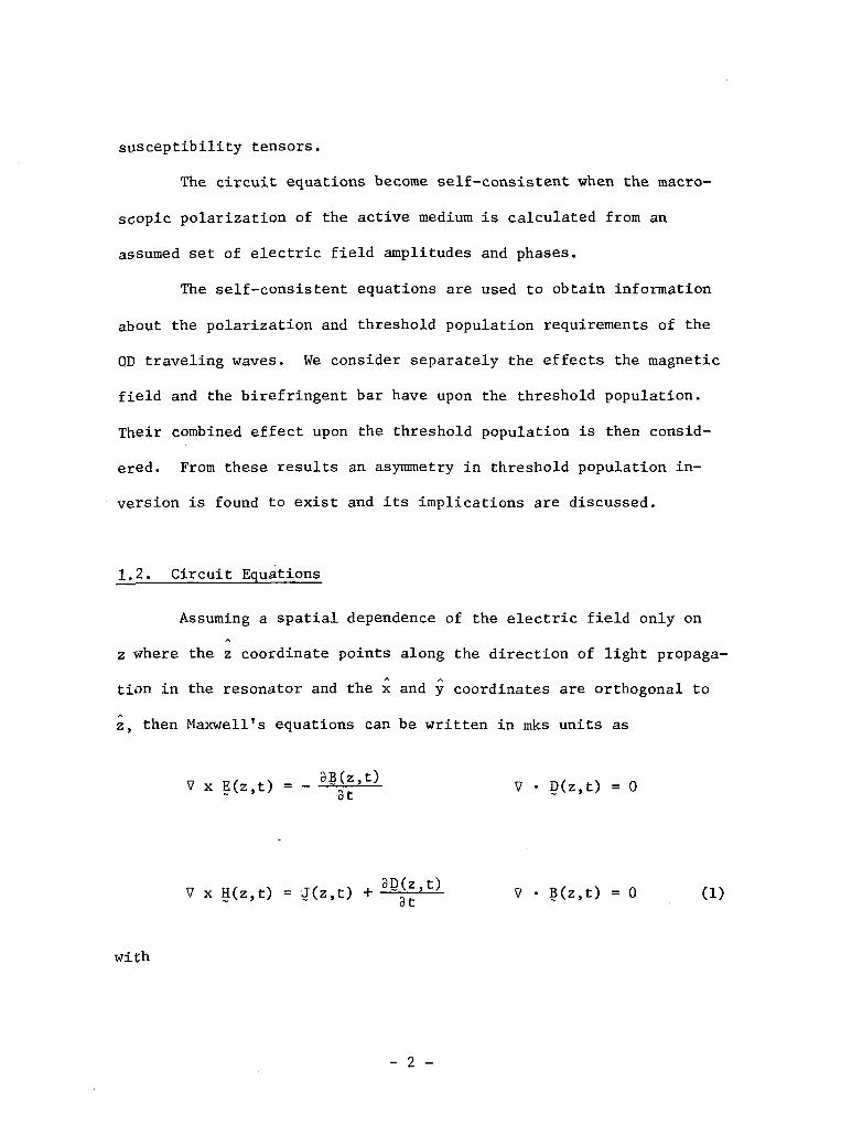
1.2. Circuit Equations
Assuming a spatial dependence of the electric field only on
z where the z coordinate points along the direction of light propaga-
tion in the resonator and the x and y coordinates are orthogonal to
z, then Maxwell's equations can be written in mks units as
V • D(z,t) = 0
V x H(z,t) = J(z,t) +̂ fz-̂ - V • B(z,t) = 0 (1)
with
- 2 -

D(z,t) = eE(z,t) + ?(z,t) B(z,t) = yH(z,t) (2)o
where E(z,t) is the total electric field in the cavity, and P(z,t)
is the polarization induced by the atomic medium. J(z,t) is the
current density. To provide for linear birefringence in the cavity,
we use a second-rank susceptibility tensor &.21 One can relate a
cavity polarization P(z,t) to E(z,t) through the tensor ^ as22
?(z't)cav
Cavity losses can be introduced by using a current density to give
J(z,t)loss = a' • E(z,t) (4)
where a1, which represents the phenomenological conductivity, is also
a second-rank tensor. Since current density is equivalent to the time
rate of change of polarization, we can combine Eqs . 3 and 4 to obtain23
J(z,t) = a • E(z,t) (5)
where
j 3t (6)
21 M. Sargent, III, et al., op. cit.
22 R. H. Pantell and H. E. Puthoff, Fundamentals of Quantum Electronics,John Wiley and Sons, Inc., 1969, p. 57.
23 M. Sargent, III, et al., op. ait.
- 3 -
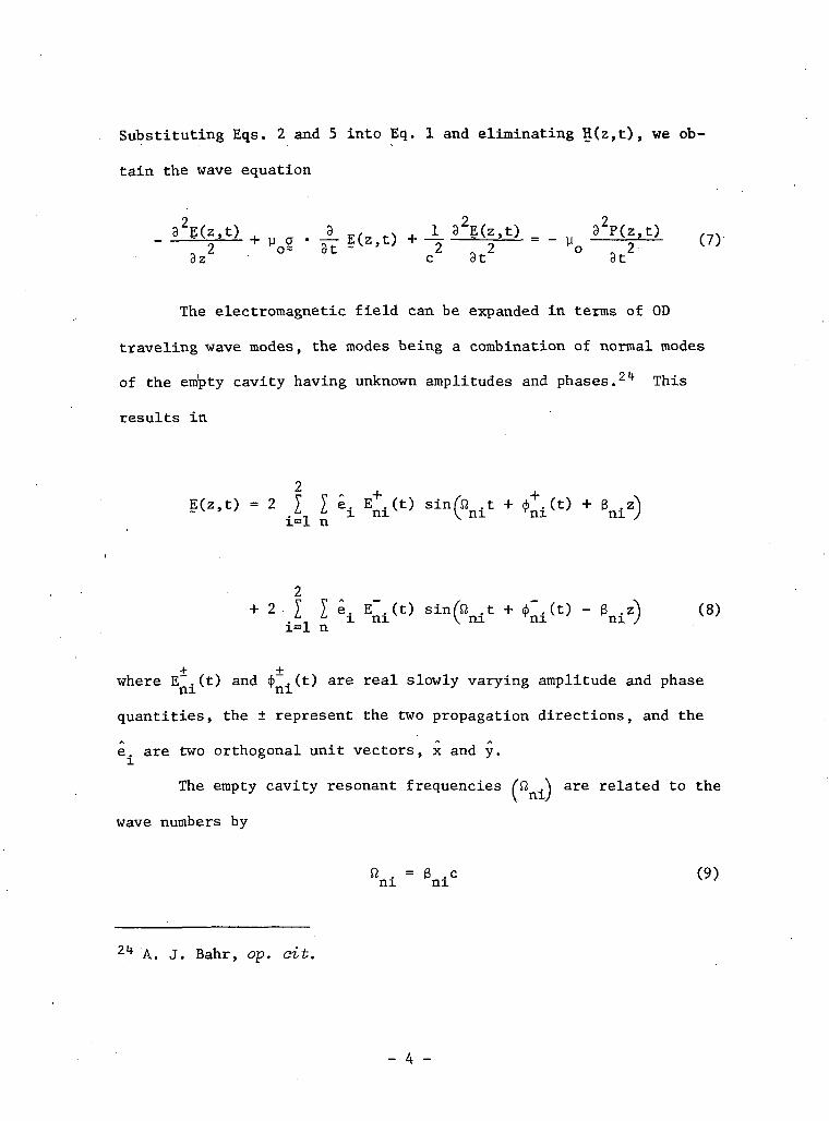
Substituting Eqs. 2 and 5 into Eq. 1 and eliminating H(z,t), we ob-
tain the wave equation
_ ) _ _8z c 3t 8t
The electromagnetic field can be expanded in terms of OD
traveling wave modes, the modes being a combination of normal modes
of the empty cavity having unknown amplitudes and phases.21* This
results in
E(z.t) = 2 I I e. E+.(t) sin̂ t + ̂ .(t) + g^x=l n
*± Eni(t) Si=l n
± ±where E . (t) and <f> . (t) are real slowly varying amplitude and phase
quantities, the ± represent the two propagation directions, and the
e. are two orthogonal unit vectors, x and y.
The empty cavity resonant frequencies (ft ..\ are related to the
wave numbers by
2lf A. J, Bahr, op. cit.
- 4 -

where ft and ft correspond to waves having polarization perpendicular
to the plane of the ring and in the plane of the ring, respectively.
The wave numbers are given by $ L = (2n + l)ir and 3 L = 2nir, where
L is the length of the cavity and n is a large integer on the order
of 10 . This difference in resonant frequencies is unique to a ring
cavity having an odd number of cavity mirrors. For example, consider
a wave emerging from point P in the cavity to be incident upon
mirror No. 1 (see Fig. 1). If the wave has a polarization which is
perpendicular to the plane of the ring, then at the mirror boundary
this wave changes phase by approximately TT, providing the angle of
incidence is less than the Brewster angle of the material.25 This
phase change occurs at each of the three mirrors giving the wave a
total additional phase change of STT in traversing the cavity. How-
ever, a wave having a polarization in the plane of the ring sees no
additional phase change in traversing the cavity. Thus, in the same
physical length, the two waves see different optical path lengths,
and hence the corresponding resonance conditions are different.
It is much easier to derive the circuit equations if Eq. 8 is
rewritten in the form
2V V ^ / "** \
~ . ̂ , *• i V ni ni ni ni / vJ-Wi=l n
where
25 S. N. Bagaev, et al., op. ait.
— 5 —

Ani(t) " Enixl" *• "ni
(ID
and
-in .t + 4>+.(t)) -ifn .t + <jT.(tj)n i ; e ^ n i V ^ +c.c
(12)
An.(t) = lE(t) e
Similarly the polarization may be written as26
2 - / - \P(z,t) = I I e. (P (t) sin & .z + P (t) cos B .z) (13)~ _-_i _ i \ ni ni ni ni yL=l n
where the quantities P .(t) and P .(t) contain the amplitude and phase
information regarding the polarization of the medium for the ni mode
of the electric field. Thus, each of these quantities has, in general,
two components for each propagation direction, one in phase with the
ni mode of the electric field, and one in quadrature. Thus, we may
write27
P .(t) = f(T. + i S'.] e v nl
ni V ni -- '
26 A. J. Bahr, op. dt.
27 Ibid.
- 6 -

ni".) e Xlli UJ-' + c.c. (14)
and
P .(t) = C . + i S . eni V ni r- '
.t
n-f' ++
28As shown previously, Eqs. 10 and 13 are substituted into Eq. 7 to
obtain a set of circuit equations for the ni mode of the electric
field. These equations are written as
•+ 1E
'ni 2
mo
\S . ) + i(s . - C . )| e f (16)
ni ni/ V ni ni v '
28 Technical Report MDL-Q31, Microwave Device and Physical ElectronicsLaboratory, University of Utah, Salt Lake City, Utah, December1969.
- 7 -
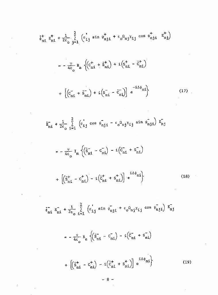
nil (17),
4e
.ni (18)
|> . E . +ni ni
/ •*•*•4e e.o
.niS .
nil (19)
- 8 -

where
i|T.. = (0 . - fl /U + (i1. - (fr (20)nji ^ nj nv Vnj n
•. - *+.LI ni
and v is an average oscillating frequency.
By determining an expression for the polarization of the active
medium in terms of amplitudes and phases of the OD waves, one can
derive the S . and C . coefficients in terms of the electric fieldni ni
amplitudes using Eqs. 13 through 15. At this point the circuit
equations become self-consistent in the amplitudes and phases of
the electric field modes.
1.3. Polarization of the Medium
As discussed in the Lamb theory,2^ excited atoms in the medium
are subjected to electric fields with assumed amplitudes and phases.
The field frequencies are near the resonance of a pair of degenerate
energy levels W and W . A magnetic field establishes a direction3. D
in space along which these energy levels are split due to the Zeeman
broadening of the atom's energy state. The atoms interact with
different frequencies not only because of Zeeman broadening but also
29 W. E. Lamb, Jr., op. eit.
- 9 -
due to Doppler effects resulting from the thermal velocity distribu-
tion of the atoms.
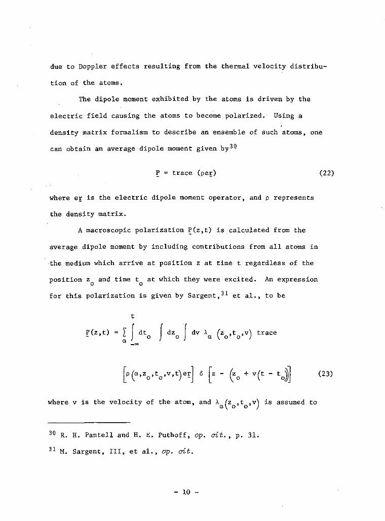
The dipole moment exhibited by the atoms is driven by the
electric field causing the atoms to become polarized. Using a
density matrix formalism to describe an ensemble of such atoms, one
can obtain an average dipole moment given by30
P = trace (per) (22)
where er is the electric dipole moment operator, and p represents
the density matrix.
A macroscopic polarization P(z,t) is calculated from the
average dipole moment by including contributions from all atoms in
the medium which arrive at position z at time t regardless of the
position z and time t at which they were excited. An expression
for this polarization is given by Sargent,31 et al., to be
t
P(z,t) = T dt dz dv X (z ,t ,v\ trace-v J o J o J • a ^ o» o' ;
[p(a,Vtofv ft)er] 6 [z - (ZQ + v(t - to| (23)
where v is the velocity of the atom, and X (z ,t .v\ is assumed to* a\ o' o' J
30 R. H. Pantell and H. E. Puthoff, op. cit., p. 31.
31 M. Sargent, III, et al., op. dt.
- 10 -
be the number of atoms excited to state a = a,b per unit time per
unit volume.
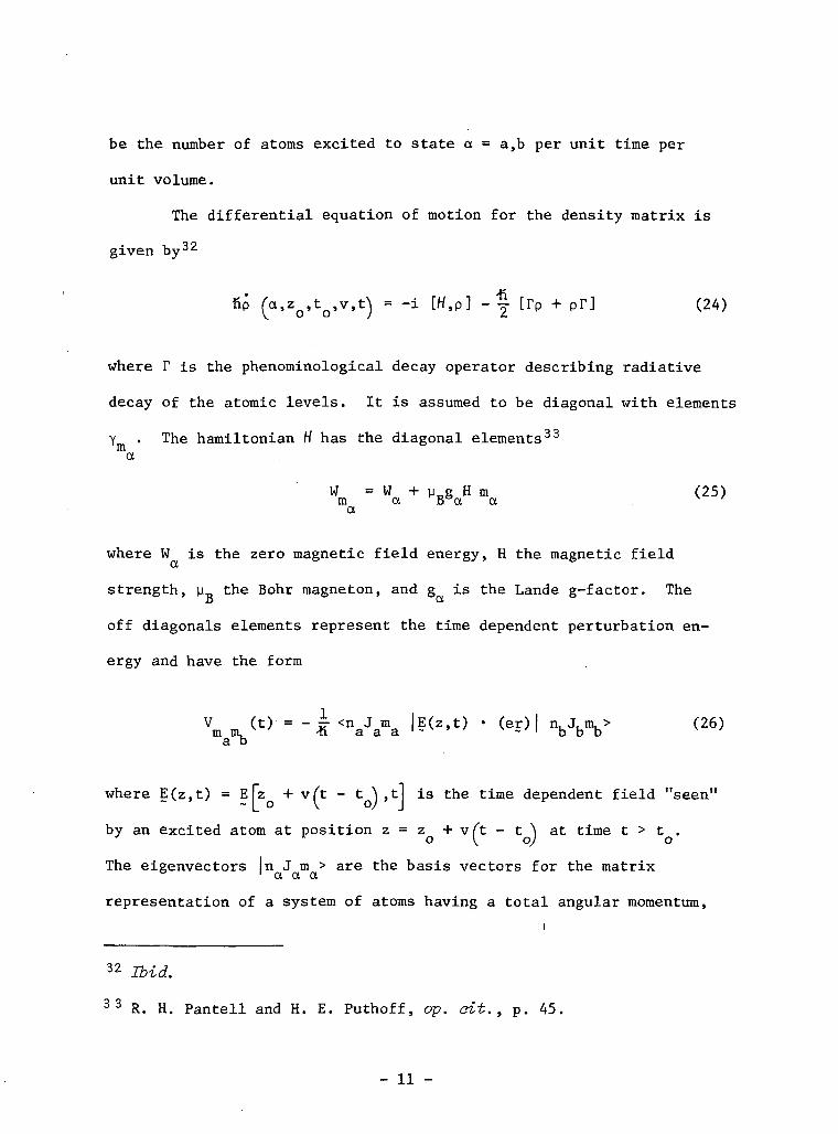
The differential equation of motion for the density matrix is
given by32
tip o , z , t , v , t = -i [ tf ,P] - [rp + pr] (24)
where T is the phenominological decay operator describing radiative
decay of the atomic levels. It is assumed to be diagonal with elements
Y . The hamiltonian H has the diagonal elements33
a
W = W + n g H m (25)m a Bea a v 'a
where W is the zero magnetic field energy, H the magnetic field
strength, y the Bohr magneton, and g is the Lande g-factor. The
off diagonals elements represent the time dependent perturbation en-
ergy and have the form
Vm " ~k <naJama '? ( z ' f c ) * <«*> I VbV <26)
where E(z,t) = E [z + v(t - t "\ ,tl is the time dependent field "seen"
by an excited atom at position z=z + vft - t ̂ at time t > t .J * o \ o) o
The eigenvectors In J m > are the basis vectors for the matrix& ' a a a
representation of a system of atoms having a total angular momentum,
32 Ibid.
33 R. H. Pantell and H. E. Puthoff, op. cit., p. 45.
- 11 -
z-component of angular momentum, and other quantum numbers represented,
respectively, by J , m , and n .a or a
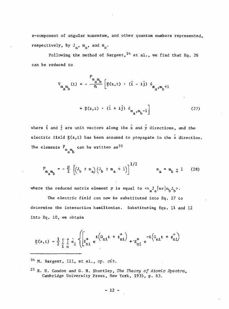
Following the method of Sargent,34 et al., we find that Eq. 26
can be reduced to
r
(t) = - -^ [E(z,t) • (i - ij) 6m
+ g(z.t) - (i + ij) « (27)
^ ^where i and j are unit vectors along the x and y directions, and the/-.
electric field E(z,t) has been assumed to propagate in the z direction.
The elements P can be written as35
Vb
n 1/2
-n r
f [(Jb * ma) (Jb *ma
where the reduced matrix element p is equal to <n J lerln, J, >.' a a1 ' TD b
The electric field can now be substituted into Eq. 27 to
determine the interaction hamiltonian. Substituting Eqs . 11 and 12
into Eq. 10, we obtain
>+.) , -ifn .t + <f>+.)ni ni7 +.E+ e V ni yni/.t +
E(z,t) =| I I "i n
. ^— i AJ .ni ni
34 M. Sargent, III, et al., op. cit.
35 E. U. Condon and G. H. Shortley, The Theory of Atomic Spectra,Cambridge University Press, New York, 1935, p. 63.
- 12 -

-Eni
(29)0 X L". | w.. -ni-y
"niT "ni ~
n - +1 we have„ 79 into Eq. 27 and defining q —«->
Then substituting Eq. 29 xnto
V (t) = -
i- E".. e
- i cos
- E'
- 13 -
- E . eni
-ifft .tV ni
t +(30)
where
(31)
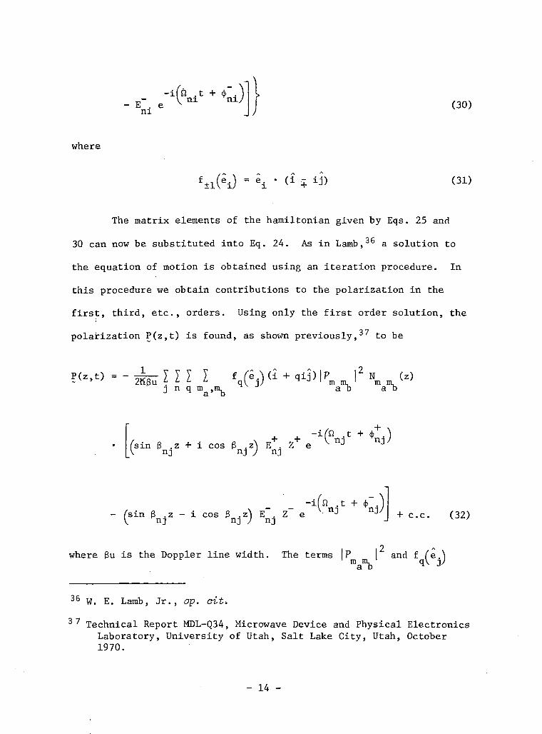
The matrix elements of the hamiltonian given by Eqs. 25 and
30 can now be substituted into Eq. 24. As in Lamb,36 a solution to
the equation of motion is obtained using an iteration procedure. In
this procedure we obtain contributions to the polarization in the
first, third, etc., orders. Using only the first order solution, the
polarization P(z,t) is found, as shown previously,37 to be
J n q
/sin 3 . z + i cos 3 .z\ E . Z eV nj nj J nj
.t +.nj
/'sin 3 .z - i cos g .z^ E . Z ev nJ nJ / nJ
.t + <f>y+ c.c. (32)
9 /^where 3u is the Doppler line width. The terms \P I and f (e. \
m nu ' qV j/
36 W. E. Lamb, Jr., op. c-it-.
37 Technical Report MDL-Q34, Microwave Device and Physical ElectronicsLaboratory, University of Utah, Salt Lake City, Utah, October1970.
- 14 -

are defined, respectively, in Eqs. 28 and 31. Z is an abbreviated
expression for Z ifv . - u> - Ym mb
which is the plasma disper-
38sion function discussed by Fried and Conte,d° where -tf<o , = Wm m m, a a a
/ - \ —W ,, Y i = 1/2 [Y + Y t j» and v . is the oscillating frequencya a a \ a a/
of the ± propagation direction. The excitation density is defined
as
a o
Aa(z) Ab(z)
m ma a
(33)
where A (z) is the number of atoms excited to the state a per unita
time per unit volume.
The excitation density N (z) for each direction is am m,a D
constant with respect to z in the active medium, which we set equal
to 1SL . Outside the active medium the excitation density is zero.Om m,a DEquation 32 is an expression for the macroscopic polarization
in terms of the traveling wave amplitudes and phases of the nj
electric field mode. As shown previously,39 ni spatial Fourier
components, P .(t) and P .(t), of the macroscopic polarization can
be obtained by projecting P(z,t) onto the respective normal modes
e. sin 3 .z and e. cos 3 .z. Then, by applying the definitions of
Eqs. 14 and 15, the C . and S . coefficients are easily determined
38 B. D. Fried and S. D. Conte, The Plasma Dispersion Function (HilbertTransform of the Gaussian), Academic Press, Inc., New York, 1961.
39 Technical Report MDL-Q34, op. oit.
- 15 -

to be
C+ = S+ = -N+xtE+ + N~f xt cos ty+ - xt sin ty+ ^ E+ (34)nx nx 1 nx \ 4 rnyx 3 rnyx/ ny v '
C = -S = N XE - N x. cos ty - X. sin ilT E~ (35)nx nx 1 nx \ b Ynyx 3 Miyxy ny v '
S+ = -C+ = -N+X̂ E+ - N+fxt cos \|)+ + xt sin *+ ^ E+ (36)nx nx 2 nx V 3 rnyx 4 nyx^ ny v '
S = C = NXE + Nx cos \l> + X sin ij;~ E~ (37)nx nx 2 nx V 3 Ynyx 4 nyxy ny
= -N+X"V" - N+fx"J" cos i^+ + xl" sin <^+ ^ E+ (38)1 ny V 4 rnyx 3 nyx^ nx v '
C + = S + +"" +""ny ny
C = -S = N XE + Nx cos ti + X sin ib E (39)ny ny 1 ny V 4 vnyx 3 nyxy nx v '
S+ = -C+ = -N+xl"E+ + N+fxt cos 4>+ - xt sin ii+ ^ E+ (40)ny ny 2 ny V 3 rnyx 4 nyxy nx v '
S = C = N X.E - N xo cos i| - X. sin ti E (41)ny ny 2 ny V 3 rnyx 4 nyxy nx v '
where, in order to discuss threshold population requirements, we have
defined
No = N± D (42)
- 16 -
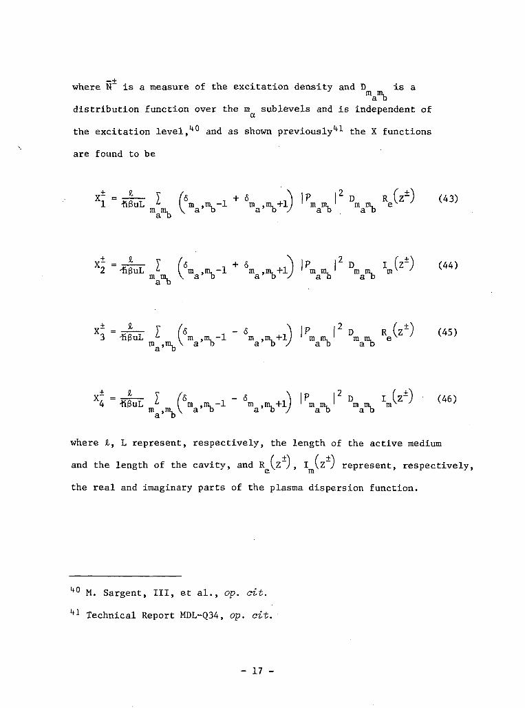
where N is a measure of the excitation density and D is am m ,a IDdistribution function over the m sublevels and is independent of
the excitation level,1*0 and as shown previously41 the X functions
are found to be
X ± = - L _ Y f 6 + 6 \ | P | 2 D Rfz 1 )1 -npuL u I m ,m, -1 m ,m, +L ' m m, ' mm, exi +,
W1 VVV Vb . Vb
o =^L-T I (& i + 5 ,.1 ) |P |D I (z1) (44)2 -nguL L I m ,m, -1 m ,m, +1 ' m m , 1 m m . m v /
m m, \ab a b / a a aba b
lp |2° R (z±)
XT =̂ |— X /6 . - 6 |P | D I z (46)4 *3uL m i t V ma'mb"1 V " " m
where £, L represent, respectively, the length of the active medium
and the length of the cavity, and R \Z~) , I vZy represent, respectively,
the real and imaginary parts of the plasma dispersion function.
40 M. Sargent, III, et al., op. cit.
41 Technical Report MDL-Q34, op. cit.
- 17 -

1.4.' Self-Consistent Equations
I.A.I. General Self-Consistent Equations
The self-consistent equations in terms of the traveling wave
amplitudes and phases can now be derived by substituting Eqs. 34
through 41 into Eqs. 16 through 19. For the ni mode of the + direc-
tion, we obtain
•+ . °xx „+.!/+' ,+ „ + . + N ,,+E + -=— E + •=— a cos ip - e n v sin \b Enx 2e nx 2e y xy rnyx o nyAxy nyxy ny
N+xtE+ + -^- N+(x+ cos / + xt sin ty+ } E+ (47)2 nx 2e V3 Ynyx 4 nyx/ nx v '
•+ °yy + 1 / '+ + + +\ +E + -Tf-^- E + -=—a cos i|> + e J2 Y sin it 1 Eny ££. ny 2e V yx nyx o nx yx nyxy nxo o ' y
" •"• " *•* " w •*» * ' •*•• ' i ' -tr ' • i ' } T-I ' f I f\ vcos it - X. sin ^ E (48)T^TT^T /I ' T^TT-^*- / T^ •Ty ^ '
O " ^o1^ 0 " \ i vT <-UO V A. SJ-LL <il I li2e 2 ny 2e V 3 rnyx 4 nyx/ nx
ft v•-(- _ + . nxAxx „ + , 1 / ' + . , + , . + + \ +» E + - ^ — E + -= — (a sin it + e ft Y cos it I Enx nx 2 nx 2e \_ xy Tnyx o ny xy nyxy nny
V —h + + V —h/ + + + + \ +-s— N X,E - -=— N (X. cos ijj - X- sin $ } E (49)/e 1 nx le V 4 nyx 3 nyxy nyo o
+E+ +-J^yjLE+ + 1 f - a '+s in/ + E f i X+ cos/ } E+
ny ny 2 ny 2e v yx rnyx o nxAyx nyxy nx
- 18 -
-=- cos / + xt sin ty+ } E+ (50)2e 1 ny 2e V. 4 nyx 3 nyx/ nx v
The analogous equations for the ni mode of the OD wave are obtained
by replacing the "+" superscript with a "-" superscript. Thus we
see that for each propagation direction, four coupled equations de-
scribe the n mode of the electric field. The equations involving
. +E . are referred to as the amplitude equations , and those involving
•±<|> . are referred to as the reactive balance equations. By using
computer techniques these equations are solvable for each mode, yield-
ing simultaneously the polarization, phase, and threshold population
inversion. We will not carry out such a detailed solution of these
first order equations since it cannot provide significantly more
meaningful results than a qualitative analysis of the equations
provides .
1.4.2. Amplitude Equations
For the purpose of discussion we consider only the equation
•+ •+involving E (Eq . 47) since similar statements hold for the E& nx ^ ny
equation and for modes of the - direction. Under the condition of
•steady state, E =0 and Eq. 47 reduces to four groups of terms.
LiX.
The two groups on the left-hand side concern the cavity parameters
of loss and birefringence. The two groups on the right-hand side
concern the action of the active medium.
The first group on the left-hand side containing the term
- 19 -

a /2e is the average loss encountered by the x component of theXjC • O
n + propagation mode. The second group on the left-hand side
represents the coupling of E to E resulting from loss anisotropy
'+ +and linear birefringence represented, respectively, by a and x
'+ +Thus, if parameters a and x 8° to zero, there would be no cou-
pling between the components from the cavity parameters.
The first group on the right-hand side contains the term
vN X2/2e , which represents the unsaturated gain encountered by the
E field component, where N is the population inversion densityrix
for the + propagation direction. The second group on the right-hand
side, containing the X_ and X, functions, describe the coupling
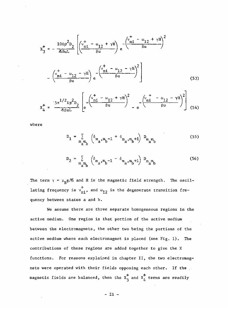
effects of the active medium. As shown previously,42 the X functions
can be rewritten approximately as
10£P2D
V **/Xl - -
ni
v̂+. -ni
Su
v . - CD.,ni ] f3u (51)
v"*" „ 1' 2 ^KguL
(V - W12 + YH
e V 3u"nl - "12 ~
(52)
ibid.
- 20 -
^Vni ' U12
Y+ „X4 -
niBu
-fiBuL
niBu
fv+.niBu
(53)
ni
- e Bu (54)
where
D, =m
im ,m, -1 m .m. + m m,a'b a' b ) ab
(55)
D2 =ffiamb
m .a D(56)
The term y = yT,g/"̂ and. H is the magnetic field strength. The oscil-D
lating frequency is v . , and u), „ is the degenerate transition fre-
quency between states a and b.
We assume there are three separate homogeneous regions in the
active medium. One region is that portion of the active medium
between the electromagnets, the other two being the portions of the
active medium where each electromagnet is placed (see Fig. 1). The
contributions of these regions are added together to give the X
functions. For reasons explained in chapter II, the two electromag-
nets were operated with their fields opposing each other. If the
magnetic fields are balanced, then the X_ and X. terms are readily
- 21 -

found to be zero, and there is no coupling between the E and E
field components. As a differential magnetic field is applied by
unbalancing the current to the electromagnets, the X. and X. terms
become nonzero and couple the field components. The principal gain
term X« is nonzero for all magnetic field values, and is typically
much larger than the coupling terms X and X,.
It is important to note from Eqs. 51 through 54 that all X
functions have approximately the same value for the + and - waves.
Consequently, the magnetic field effects on the two OD waves are
essentially the same. One also notes from Eqs. 47 through 50 that
there is no coupling between the OD waves in first order.
1.4.3. Reactive Balance Conditions
Equations 49 and 50 are referred to as the reactive balance
equations. Using Eqs. 47 and 48 in Eqs. 49 and 50, we can obtain
solutions for the quantities 4> and ^ which contain information
about the oscillating frequencies. The oscillating frequencies
• •v and v are related to (j) and <f> in the following way:
v = n + 4.nx nx Tnx
v = n + <J> (57)ny ny Yny
where ft and Si are the empty cavity eigenfrequencies defined in
Eq. 9.
Considering Eq. 49 we see that the nx + mode experiences a
- 22 -
frequency shift resulting from linear birefringence represented by
the term ft x /2- Additional frequency effects occur in the form ofIlX XX
tcavity coupling terms when a and/or x are nonzero. Frequency
xy xy
pulling due to the presence of the active medium results from the
term vN X.. /2e . Additional coupling effects also result from the
magnetic field and are represented by the last group on the right-
hand side of Eq. 49.
The eigenfrequencies ft and ft correspond to waves having
polarization perpendicular to the plane of the ring and in the plane
of the ring, respectively. As we have shown previously, the eigen-
frequencies ft are displaced from the eigenfrequencies ft by Aft =
TTC/L. In order to support oscillation of waves with an electric
field vector having a component not only perpendicular to the plane
of the ring, but also in the plane of the ring, we require that
components along each direction have the same oscillating frequency,
i.e., v = v . For this to hold we must have, from Eq. 57nx ny
• Trr*= *ny + (2k + X) IT k = °'1'2' (58)
The index k .is allowed to take on values other than zero. This accounts
for cavity birefringence, etc., which causes a different refractive
index to be "seen" by waves having their field components directed
along the x direction as opposed to directed along the y direction.
Using this condition in Eq. 49 and subtracting the result from Eq. 50,
we obtain
- 23 -
nx
nyO+£cos i|i + X0 sin i f ) ' 1 + —^- (-a1 sin 1(1'nyx 3 nyxy 2c V yx nyx(Vv y*
e ft X cos illo nx yx ny+ \
i Inyx/ny
-
nx
__ i
vN15 —2e
/v+ .+ v+ . .+ "\X. cos ty - X, sin 1(1 IV 4 nyx 3 nyxy
- -T— (a sin \ii + e fi Y cos ilj )2e V xy nyx o ny xy nyxy
= (2k + 1) •=£- - -2 V ny yy Xnx xx (59)
The similar result for the OD wave is obtained by replacing the "+"
superscripts by "-" superscripts. The only waves which can be
resonant in the cavity are those which satisfy Eq. 59. These waves
will in general have an elliptical polarization with electric field
components along x and y, differing in phase by \j> while having annyx
amplitude ratio E /E . As the bar is varied in angular position,
the a' and x terms will change. Likewise, as the magnetic field in
the active medium region is varied, the X terms change. These varia-
tions cause the parameters in the reactive balance equation (Eq. 59)
to vary. Hence, waves satisfying the new conditions will have a
different phase and/or amplitude ratio from the waves satisfying the
previous condition. Thus, we can say that as the bar is varied in
angular position and/or the magnetic field is changed, the
resonant waves will in general experience a change in polarization.
- 24 -

One can also predict that, if the combined parameter variations are
different for the two directions, the polarization of the OD waves
will change differently. As discussed above and shown previously,43
the X functions have approximately the same values for the + and -
directions. We must therefore determine how the a' and x terms vary
as a function of bar orientation, and whether they are different for
the two propagation directions.
1.4.4. The a* and x Terms
To calculate the a' and x matrix elements, we begin by deriv-
ing a transfer function which describes light propagation from the
active medium through the birefringent bar. From a given point in the
active medium, the bar appears different for the two propagation direc-
tions since in one direction waves from the active medium region re-
flect from one cavity mirror before entering the bar, and for the
opposite direction waves reflect from two cavity mirrors before enter-
ing the bar. Thus, two transfer functions are necessary, one describ-
ing each propagation direction.
For waves reflecting from one cavity mirror before entering
A
the bar, the x component suffers an additional TT phase shift from
the y component, thus the components will have optical path lengths
differing by X/2 from any given point in the medium to the entrance
point on the surface of the bar. We can account for this in the
transfer function by replacing E by E e = -E , and then"X ""X ""X
1+3 Ibid.
- 25 -
transforming to the bar coordinate system which is at some angular
orientation with respect to the laser coordinate system. For the
opposite direction waves reflect from two cavity mirrors before
entering the bar. Therefore, the path lengths of the x and y components
differ by X from a given point in the medium to the entrance point on
the bar's surface, and hence there is no coordinate reversal. Thus,
/». A
we may transform the x and y field components directly to the bar
coordinate system.
In order to relate the a1 and x terms to the transfer functions,
each function is separated into a fictitious loss and birefringent
element. The combination of the two elements is required to have the
same transmission characteristics as the transfer function.'*4' From
the loss element a phenomenological a' tensor is found having an
equivalent loss distributed evenly over the cavity. Similarly the
birefringent element is used to determine the phenomenological x ten-
sor having an equivalent birefringence distributed evenly over the
cavity.
As localized elements occupying a small region of the cavity,
the bar and Brewster windows cannot be treated as a perturbation on the
existing normal modes. Thus, we distributed their effects over the
cavity such that they could be treated as perturbation terms .l+5»lt6
44 G. N. Ramachandran and S. Ramasheshan, "Crystal Optics," Handbuchder Physik, Vol. XXV/1, Sections 12 and 13.
1+5 W. E. Lamb, Jr., op. cit.
46 M. Sargent, III, et al., op. cit.
- 26 -

As shown previously,"*7 these operations result in the following
matrix elements:
a'+ * 7 x 10~4 a' = 7 x 10 4yy yy
'+ -4 '- -4a = .67 x 10 . a = .67 x 10XX XX
'+ '+ -4 '- '- -4a = a = -.041a x 10 a = a .041a x 10xy yx xy yx
'+ '+ -4 '- '- -4e vx = e vx - .74a x 10 e vx = e vx - = -.74a x 10o xy o yx o xy o yx
(60)
where a is bar rotation about the transverse axis in degrees (see Fig. 3
and discussion in chapter II). The effects of Brewster window loss
have been included in the a and a terms.yy xx
One notes from Eq. 60 that the coupling terms (off diagonal
matrix elements) are opposite in sign for the two propagation direc-
tions.
1.5 Discussion
We conclude that for a given set of parameter values in Eq. 59,
there is a particular value of E /E and \1> which will satisfy the^ nx ny vnyx 3
equation. When these parameters are changed, the polarization, that is,
Technical Report MDL-Q33, Microwave Device and Physical ElectronicsLaboratory, University of Utah, Salt Lake City, Utah, July 1970.
- 27 -
E /E and fy will vary. One notes from Eq. 60 that the couplingnx .ny nyx J ^ re
terms (off diagonal matrix elements) are opposite in sign for the two
propagation directions. Thus the parameters in the reactive balance
equation change differently for the + and - directions leading to
different polarization changes between the OD waves.
If we had modeled a four-mirror cavity instead of the three-
mirror cavity, each wave would have suffered the same additional
phase shift in going from the active medium to the bar. Consequently,
the a' and x terms for the two directions would be the same. In this
case, we would not expect different changes in the polarization of
the OD waves for small rotations of the bar.
We would like to make predictions about the amplitudes of the
OD waves as a function of differential magnetic field and bar orienta-
tion. Indications about the relative amplitudes can be obtained from
the threshold population (N ̂ \, the threshold population being the
minimum inversion necessary to overcome the cavity losses. We argue
that waves having a threshold population requirement which is higher
than other waves will tend to have a lower oscillating amplitude. To
obtain the threshold population Eq. 47 is substituted into Eq. 48 and
the result is solved for N. Upon doing this for the + wave, we obtain
—I-an approximate expression for N , ; the corresponding expression for
the - wave is obtained by replacing the + superscripts with - super-
scripts.
/ ± N 2 . 2 ± ' ± 2 2 , ±I e vx sin ib -a cos w\ o xyy nyx xy m
- 28 -

+ \2 2 +T— 1 • *• i —
nyx
•± T + ± ± '±1. .o . vX0 e vx . . .+ vX. a sin 2\t», xx L 3 o xy 4 xyj [
' +2a ~yy
nvx—i— + smaller terms (61)
*± *± '+ ± ± ± ±where we have assumed a » a , a , e vx and X0 » X_,X.. Theyy xx' xy o xy 2 34
a1 and x terms are given in Eq. 60, while the X terms are given in
Eqs. 52 through 54.
Equation 61 is valid providing E and E are not zero. For
example, if the opposing magnetic fields are balanced and the bar is
+ + '+ '+oriented with a = 0, then the terms X,., X,, a and x are zero,3 4 xy xy '
and no coupling takes place between the field components. The field
component E , which has high loss, consequently is below threshold
and therefore is zero. Thus, we must derive the expression for
threshold population from Eq. 47.
Upon doing this we obtain the expression
__ 4- w
N-h - -S- (62)vX_
We see from this equation the minimum condition for oscillation is
determined by the loss along the x direction. The vX~ term is
associated with the unsaturated gain each mode receives in passing
through the active medium.
- 29 -
Consider the case where the bar is in the null position, i.e.,
a and Y are zero. Under these conditions a differential field isxy Axy
set up by unbalancing the current to the electromagnets causing X~
and XT to become nonzero. Now both E and E are nonzero, because4 nx ny
of the coupling terms, and we can use Eq. 61 to obtain an expression
for the corresponding threshold population. Upon doing this we
obtain
(63)
We note from this equation that N increases as the differential
field is applied provided
f +\2 2 + ( +^2 2 +(vX: ) cos iT > (vXT ) sin \l>~ (64)V 37 nyx V 47 ^nyx v
We find that for most of the oscillating modes, i.e., twelve of the
i +1 . +.twelve to fifteen oscillating modes, |vX | > |vX.|. The only modes
which do not obey this inequality are those located furthest from line
center, and these modes have small amplitudes if they oscillate at
all. If the phase angle i|T is near 90°, the inequality in Eq. 64
+would not hold. However, experimentally we find that ty is a
relatively small angle for both directions. But this experiment was
performed in the oscillating laser which would give some weighted
average ^ over all oscillating modes. If we assume, though, that \l>
- 30 -

0" /+ XX I
Th v± I1
2 V4a>:t /yy/
ia ±vX*yy 2
(e VX I_V o Axy/
does not vary appreciably from mode to mode, Eq. 64 is easily satis-
fied for the oscillating modes, and the threshold population will
increase for all modes in either direction as the differential
magnetic field is applied to the active medium. Consequently, we
are lead to believe that in the oscillating laser, the amplitudes of
the OD waves will decrease as the differential field is applied.
Consider now the case of rotating the bar such that a and& xy
X are nonzero while maintaining balanced magnetic fields. In this
situation Eq. 61 can be written as
2 2 ± '±2 2 ±sin iii - a cos ii>
nyx xy Tnyx _
(65)
We note from Eq. 60 that |e vx | » |a | and the second factor ofn ' o xy1 ' xy1
Eq. 65 is positive provided ijT is greater than approximately 3°XI yX
which we find, experimentally, to be true for the average ty
mentioned above. Thus, as a is increased by rotating the bar, the
threshold population requirement increases for both directions sincef\
(x ) is positive. This indicates that the oscillating amplitudeV xy/
for modes in both directions will decrease as the bar is rotated away
from a = 0.
As a final case we consider the combined differential magnetic
field and birefringent bar at a ̂ 0. Now all terms of Eq. 61 are non-
zero and,as discussed, the second and third terms are positive, adding
to the first term. However, the fourth term behaves differently. It
- 31 -
can be written approximately as
1 f ±\f ±\a [vX0 I e vx sin 2. xx \ j/\ o xy/ LIV^. tc.c.\+ - '+ / +\2 — <66>
2a - vXl)yy V 2/
± '±where we have assumed e vx » a as shown in Eq. 60. As discussed
I
above and as shown previously,^8 the term vX~ for each mode is
essentially independent of the propagation direction. The angle 2i/>~
has been found experimentally to be between 0 and 90 degrees for both
+ and - propagation directions. However, as discussed above, this is
an average i|) over all oscillating modes. The term e vx changeso ^*ysign with propagation direction. As a consequence Eq. 66 adds to the
first three terms of Eq. 61 causing an increase in N , , but for the
opposite direction it subtracts from these terms causing a drop in
N_, relative to the opposite direction. If the bar is rotated in the
opposite direction (-a), the opposite will occur, i.e., N , for the
direction which increased for +a will now decrease while the OD wave
will experience as increase in NT, . We can therefore predict an
asymmetry in the threshold population of the OD waves, the asymmetry
being caused by the combination of a differential magnetic field and
a birefringent bar placed in a three-mirror ring cavity. This implies
that an amplitude asymmetry is likely to occur in the oscillating
laser. If we had used a four-mirror ring cavity, the asymmetry in N ,
48 Technical Report MDL-Q34, op. cit.
- 32 -

would not exist since the x and a terms would not change sign forxy xy
the two propagation directions and we would not expect an amplitude
asymmetry to occur.
- 33 -

II. EXPERIMENTAL RESULTS
2.1. Introduction
Asymmetric amplitude changes can be induced between the OD
traveling waves in a three-mirror ring laser cavity. These changes
are found to occur for certain orientations of an inner-cavity
birefringent bar when an axial magnetic field is applied to the active
medium.
We describe experimentally the behavior of the amplitude
changes in a laser operating in twelve to fifteen free-running modes.
The amplitude asymmetries are shown to be accompanied by asymmetric
polarization changes. Asymmetric polarization changes are also
found to exist on a single pass when two elements are utilized, one
of which causes reciprocal changes to occur in the polarization of
the OD waves, the other of which causes nonreciprocal changes to
occur in the OD wave's polarization. We show that an element caus-
ing such nonreciprocal changes is the active medium in the presence
of an axial magnetic field, and how a birefringent bar placed in a
three-mirror cavity can be made to induce reciprocal changes in the
polarization of OD waves. We describe how the theory predicts that
this combination of elements also leads to the observed amplitude
asymmetries. Additional supporting experiments which give greater
insight into the operation of the device are presented; however, an
explanation of these results in terms of the theory is not attempted.
- 34 -

2.2. Experimental Apparatus
The ring cavity is mounted on a 5' x 6' slab as shown in
Fig. 2. The three-legged cavity has a total length of 410 cm. Each
mirror is the dielectric layer type with a transmission of 0.05 per-
cent. The amplifier tube is placed in one leg of the cavity, and has
an active length of 125 cm. The laser operates at A = 6328 A. The
plasma is dc excited and is sustained between a centrally located
cathode and two anodes which are near each end of the tube. The
current in each leg is approximately 35 mA. The ID of the bore is
3 mm, which restricts operation to the fundamental transverse mode.
Brewster-angle windows of fused silica glass enclose the ends of the
tube; they are aligned with each other to ±5 minutes. The tube is
filled to a total pressure of approximately 1.3 torr. A mixture of
3 205.5 to 1, He to Ne (99.95 percent isotopically pure), was used.
With this pressure and mixture, the tube has a single-pass gain of
approximately 10 percent. In most of the experiments which are
described, the laser operated in twelve to fifteen free-running modes.
Two electromagnets, each 34 cm in length, are symmetrically
placed over the amplifier tube as shown in Fig. 2. Each magnet
supplies an axial magnetic field of approximately 67 gauss/amp.
The inner-cavity birefringent bar is a 6 x 2 x 20 mm quartz
crystal. The c-axis is along the long length of the bar; the other
axes lie in the 2 and 6 mm directions. The bar is housed in a gimbal
mount which allows rotations about three axes which intersect in the
middle of the bar. The "longitudinal" axis lies in the intersection
- 35 -
Detector
L = 410 cm
(b)
Fig. 2a. Schematic diagram of the ring laser showing the position ofthe electromagnets and the quartz bar. The polarization ofthe OD waves is measured from the output of mirror No. 3, whiletheir amplitudes are measured from the output of mirror No. 2.R = 6 m, 3 m, and infinity for mirrors Nos. 1, 2 and 3, respec-tively.
b. Picture of the ring laser.
- 36 -

of the plane of the ring and the plane normal to the beam in which
the bar is placed. The "transverse" axis is perpendicular to the
longitudinal axis and makes an angle G with the plane of the ring
(see Fig. 3). The angle 0 is varied by rotating the transverse axis
about the longitudinal axis. The "normal" axis is perpendicular to
the entrance and exit surfaces of the quartz bar, and moves with the
bar as shown in Fig. 3. The bar's c-axis is aligned along the trans-
verse axis.
2.3. Bidirectional Operation
Bidirectional operation, i.e., simultaneous oscillation of
waves traveling in both the clockwise (cw) and counterclockwise (ccw)
directions, is necessary for successful orientation sensing. In
large multimode ring lasers utilizing a single neon isotope, uni-
directional operation predominates.49 However, we find that when a
current of approximately 2 amps is supplied to each electromagnet,
stable bidirectional operation occurs. These unidirectional effects
result from gain competition between the oppositely directed (OD)
waves, which is presumably the multimode analogy to the single mode
competition effects discussed by Aronowitz.50 In the single-mode
20 22case, the competition is reduced by using a mixture of Ne and Ne ,
o1+9 R. Pohle, "A Possible Explanation of Unidirectionality of Large Ne
Ring Lasers," Physics Department, University of Maryland, CollegePark, Maryland, unpublished, June 6, 1967.
50 F. Aronowitz, op. sit.
- 37 -
Longitudinalaxis
/"" Transverseaxis
90 - 9
Beam
Normal axis
(a)
00
Fig. 3a. Schematic diagram of the quartz bar showing the three axes; thebar's c-axis is aligned along the transverse axis.
b. Enlarged view of the bar.
- 38 -
which produces two Doppler gain profiles separated by the isotopic
shift. It is probable that in our case the competition is reduced in
a similar way by producing two Doppler profiles separated by twice
the Zeeman shift. While allowing bidirectional operation, the mag-
netic field also quenches any oscillation at X - 3.39 y which may be
present.51
2.4. Asymmetric Amplitude and Polarization Changes
As indicated in Fig. 3 the bar is placed in the ring cavity with
its c-axis along the transverse axis. Balanced opposing magnetic
fields are applied to the active medium by supplying a current of 3
amps to each electromagnet. This maintains bidirectional operation
while presumably canceling any induced polarization rotating effects
caused by the fields. Under these conditions the average power in
each direction is "normalized" to the same value. Upon producing a
differential axial field of 167 gauss (decreasing the current in one
magnet to 1.75 amps and increasing the other to 4.25 amps), we find
that at certain bar orientations, the average power in one direction
increases while the average power in the other direction decreases,
or, equivalently, there is an amplitude asymmetry in the OD waves.
The asymmetric effect has the following characteristics. If
a = 0, that is, if the normal axis is initially positioned in the
"null plane," i.e., the plane formed by the beam and transverse axis,
51 W. E. Bell, A. L. Bloom, "Zeeman Effect at 3.39 Microns in aHelium-Neon Laser," Applied Optics, Vol. 3, No. 3, March 1964
pp. 413-415.
- 39 -

the amplitude of the OD waves remains essentially constant as the
differential magnetic field is applied to the active medium. However,
if the bar is rotated so that the normal axis rotates about the trans-
verse axis out of the null plane, (a ̂ 0), then, upon applying the
same field, the amplitude of one wave increases while the amplitude
of the OD wave decreases. If the normal axis is rotated out of the
null plane in the opposite direction, the opposite occurs, i.e., the
wave which increased before now decreases in amplitude while the OD
wave increases in amplitude.
The percent increase or decrease in magnitude of the OD waves
for various bar orientations is shown in Fig. 4. As noted in this
figure, the angular orientation of the bar can be determined by
measuring the magnitude and sign of the asymmetry in the OD waves.
Similar amplitude asymmetries were found to exist when the
power levels of the OD waves were decreased to near threshold values.
To determine how the polarization of the OD waves changes when
the amplitude asymmetries occur, the following experiment, as
illustrated in Fig. 2a, is carried out. The polarization of the OD
waves is measured from the output of mirror No. 3, while their inten-
sities are measured from the output of mirror No. 2. As before, the
opposing fields are applied supporting bidirectional operation, and
the bar is placed in the cavity with its normal axis in the null
plane (a = 0) . The polarization of both waves is found to be slightly
elliptical. As the bar is rotated to a = 2°, the main polarization
components of the OD waves are rotated approximately 6° away from their
- 40 -

B-S
oo
M-lM-lO
50
40
30
20
10
-10
-20
-30 -
-40 -
-50 -
Clockwise
Rotation abouttransverse(degrees)-
Fig. 4. Percent increase and decrease in the intensity of the OD wavesfor various values of a, that is, for various bar orientationsabout the transverse axis when the differential field of 160gauss is applied. The straight lines are least square fits todata (taken at position of maximum sensitivity).
- 41 -

null plane values, while the amplitudes of both waves decrease equally.
The differential field is then applied. The main polarization com-
ponent of the clockwise wave rotates approximately 1° back toward its
null plane value, while the wave amplitude increases. The counter-
clockwise wave, which decreases in amplitude, has its main polarization
component rotated about 1° further from its null plane value. If the
bar is, however, rotated to a = -2°, the opposite occurs as the
differential field is applied, i.e., the counterclockwise wave, which
now increases in amplitude, has its main polarization component
rotated back toward its null plane value, while the clockwise wave,
which now decreases in amplitude, has its main polarization component
rotated still further from its null plane value. Thus a polarization
asymmetry is found to occur simultaneously with the amplitude
asymmetry.
In the above experiments the OD traveling waves were found to
be elliptically polarized. To determine the phase difference between
the x and y field components (tj>) , the above experiment was repeated.
The amplitudes of the major component of polarization, the minor
component of polarization, and the angle (g) between the major polariza-
tion component and the x field component (without the bar in the cavity
and without magnetic fields applied) were measured for each OD wave.
This was accomplished by allowing the output from mirrors No. 1 and
No. 2 to pass through a polarizer and then into a detector (see Fig. 1).
From this information the phase i/> between the x and y field components
is found by solving the transcendental equations given by Born and
- 42 -

Wolf,5^ With the bar in the cavity (as shown in Fig. 3) and balanced
fields, the results for one direction are shown in Table 1. For the
Table 1. Determination of phase angle fy between the x and yfield components for a balanced magnetic field.
a.(Degrees)
0
3
-3
(Degrees)
1.5
9
-10
Amplitude ofMajor Polarization
Component(Arbitrary Units)
1.6
1.15
1.2
Amplitude ofMinor Polarization
Component(Arbitrary Units)
.04
.045
.053
(Degrees)
40°
14°
194°
OD directed wave we obtain approximately the same results. For a given
a, i.e., a = 0,3,-3 degrees, the phase angle ty is found to vary for
both directions as the differential field is applied. Due to measure-
ment error it was difficult to determine the amount of this angular
variation; however, it appeared to be less than two degrees for each
value of a.
The variations in the polarization of the OD waves indicated
in Table 1 are in agreement with the changes in the polarization of
the OD waves found by Burrell,53 et al. The change in \jj as a varies
52 M. Born and E. Wolf, Principles of Optics, Pergamon Press, 1965, p. 27.
53 G. J. Burrell, T. S. Moss and A. Hetherington, "Beats Produced byNegative Faraday Effect in Infrared Ring Lasers," Infrared Physics3Vol. 8, 1968, pp. 199-208.
- 43 -
from 3 degrees to -3 degrees is also predicted by Troshin,5L( et al.,
using the Poincare sphere method of analysis.
The results of the above experiments are summarized as follows.
With the laser operating in twelve to fifteen free-running modes, the
fields are balanced; we find that as the bar is rotated about the
transverse axis such that a ̂ 0, the amplitudes of the OD waves de-
crease. Such behavior is predicted by the threshold population require-
ment in Eq. 62. Then, as the differential field is applied, we find
that for a ̂ 0 the asymmetries occur. This behavior is also in agree-
ment with theoretical predictions as in Eq. 63.
We also find polarization asymmetries to occur between the OD
waves, as one would expect from the discussion of the reactive balance
equations.
2.5. Related Experiments
To more thoroughly understand the polarization asymmetries and
the role the three-mirror cavity plays in the asymmetric effects,
several additional experiments have been performed. We will now ex-
plain a few of the more significant of these experiments.
The polarization of the waves in the ring laser is determined
by several factors, the Brewster windows, resonance conditions in the
B. I. Troshin and S. N. Bagaev, "Use of the Poincare Sphere Methodfor the Analysis of the Polarization Characteristics of a Laserwith an Anisotropic Element," Optics and Spectroscopy, Vol. 23,No. 5, November 1967, pp. 424-425.
- 44 -
three-mirror ring cavity, the quartz bar, and the magnetic field
effects upon the gain atoms. Polarization effects occur due to the
Brewster windows because they have a minimum reflection loss for
only one linear polarization.
As we have discussed in chapter I an empty three-mirror
cavity can only support waves having one of two polarizations — waves
having a polarization perpendicular to the plane of the ring, and
waves having a polarization in the plane of the ring. This is
illustrated in the following experiment. Without the bar in the
cavity, the amplifier tube is positioned so that the Brewster windows
have minimum reflection loss for waves with polarization perpendicular
to the plane of the ring. The current to the electromagnets is
turned off causing unidirectional operation. When the tube is
rotated about its axis away from this position by as little as ±4°,
the amplitude of either OD wave is greatly reduced, and its polariza-
tion, while remaining essentially linear, is rotated by approximately
±2°. For tube rotations of ±6°, both OD waves are completely extin-
guished. Similar results were obtained by Bagaev,55 et al. In a
cavity with an even number of mirrors, the restriction on the allowed
polarization is lifted since the resonant cavity length for both
polarizations is now the same. For example, we find that in a four-
mirror ring cavity, the amplifier tube must be rotated by as much as
20° to cause any significant amplitude changes.
55 S. N. Bagaev, et al., op. oit.
- 45 -
There are several sources of polarization effects in the quartz
bar. The bar, like the Brewster windows, has a minimum reflection
loss for only one polarization. However, the significant property of
the bar is its birefringence since the asymmetries disappear when the
quartz bar is replaced with an isotropic glass bar. The birefringence
of the quartz bar is the source of two types of behavior; one is beam
splitting, the other is a change in the polarization. Calculation
shows that the magnitude of the beam splitting due to birefringence
is about one percent of the average beam diameter. Since this split-
ting is so small, it is doubtful that it contributes to the asymmetric
effect. Regarding polarization changes, a linearly polarized wave
entering the quartz bar will, in general, exit with an elliptical
polarization. As the bar is rotated in one angular direction about
the transverse axis, we find experimentally that a wave "A" traveling
on a single pass through the bar (as shown in Fig. 3) has its main
polarization component rotated in a clockwise manner, "viewed" face
on into the propagation direction of "A". For the same bar rotation,
wave "B" traveling through the bar in the opposite direction has its
main polarization component rotated in a counterclockwise manner,
"viewed" face on into the propagation direction of "B". Thus, as the
bar is rotated about the transverse axis, the main polarization compo-
nents of waves traveling through it in opposite directions are rotated
in a nonreciprocal manner. However, if the light travels on a single
pass through a three-mirror/quartz bar combination (such as in Fig. 5a)
then, when the bar is rotated as above, the main polarization components
- 46 -
Bar
(a)
(b)
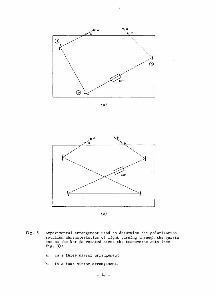
Fig. 5. Experimental arrangement used to determine the polarizationrotation characteristics of light passing through the quartzbar as the bar is rotated about the transverse axis (seeFig. 3):
a. In a three mirror arrangement.
b. In a four mirror arrangement.
- 47 -

of the OD waves are rotated in a reciprocal manner. This is shown in
the experiment which is illustrated in Fig. 5a. The OD waves "A" and
"B" enter the three-mirror/quartz bar combination with linear polariza-
tion perpendicular to the plane formed by the three mirrors. Wave "A"
travels past mirrors No. 1 and No. 2 and arrives at the bar with a
polarization still perpendicular to the plane formed by the three
mirrors. As the wave passes through the bar, its polarization becomes
elliptical. When the bar is rotated about the transverse axis in one
angular direction, the main polarization component of wave "A" is
rotated in a counterclockwise direction. This rotation becomes clock-
wise upon reflection from mirror No. 3 and the wave exits the arrange-
ment with polarization rotated clockwise. Wave "B" travels past mirror
No. 3 and also arrives at the bar with a polarization perpendicular
to the plane formed by the three mirrors, and upon passing through
the bar, its polarization becomes elliptical. When the bar is rotated
in the same manner as above, the main polarization component of wave
"B" receives a clockwise rotation. Mirror No. 2 changes this to aI
counterclockwise rotation while mirror No. 1 changes it back to clock-
wise rotation, so wave "B" also exits the arrangement with polarization
rotated clockwise. Thus, for bar rotations about the transverse axis,
the main polarization components of the OD waves are rotated in a
reciprocal manner when traveling on a single pass through a three-
mirror/quartz bar combination. On the other hand, with an even number
of mirrors, such as the four-mirror/quartz bar combination shown in
Fig. 5b, this is not the case. We now find for the same bar rotations
- 48 -

that the OD waves are rotated in a nonreciprocal manner. The same
reciprocal/nonreciprocal behavior was observed when the quartz bar
was replaced with, respectively, a Faraday rotator and a quarter-
wave plate at various orientations.
To observe how the axial magnetic field in the active medium
influences the polarization of waves passing through it, the follow-
ing experiment was performed. Linearly polarized light from a three-
mode laser (Spectra Physics 130 C) was passed through the discharge
of the active medium. When the axial field is increased in one direc-
tion from 0 to 130 gauss, the polarization becomes elliptical with
the main polarization component receiving a clockwise rotation of
approximately 0.5°. If the light is passed through the discharge in
the opposite direction and the experiment repeated, the main polari-
zation component receives a counterclockwise rotation of approximately
0.5°. Thus, the main polarization components of OD waves are rotated
in a nonreciprocal manner. We have been unable to find magnetic
field experiments similar to the above at A = 6328 A in the literature;
however, related work is reported in several articles.56"59
If the three-mirror/bar combination and the active medium in
the presence of an axial magnetic field are combined as in Fig. 2a, •
then, on a single pass, different polarization changes occur depending
56 M. Sargent, III, et al., op. cit.
57 R. G. Buser, et al., op. cit.
58 C. V. Heer, et al., op. cit.
59 G. J. Burrell, et al., op. cit.
- 49 -

upon which direction the waves are traversing the cavity.
It is difficult to draw such a single pass analogy for the
amplitudes of the OD waves. However, in terms of the theoretical
analysis such a combination of elements are necessary to set up an
asymmetric threshold polarization. If such a combination were not
used, for example, if we had used the same experimental arrangement
in a four-mirror cavity, then the OD waves in first order would vary
the same from a threshold population standpoint, and consequently
should have equal amplitudes in the operating laser. It is important
to note that we have been unable to observe asymmetric amplitude
effects or asymmetric polarization changes between the OD waves in
a four-mirror ring cavity.
2.6. Rotations About the Longitudinal and Normal Axes
We would like to know how the asymmetries vary for rotations
of the bar about the other two axes — the longitudinal axis and the
normal axis.
We find that the sensitivity (percent difference in intensity
versus angle of rotation) of the asymmetric effect depends upon the
angular position of the bar about the longitudinal axis. The maximum
sensitivity occurs at one particular angular position fQ \ of the
transverse axis (see Fig. 3). At this angular position the light is
incident on the bar at approximately the Brewster angle of quartz.
The data in Fig. 6 show the maximum sensitivity to be approximately
17 percent/degree. It is not understood why the sensitivity decreases
- 50 -

H tCO I
4J C3 iH COO T3 CO,Q 3 <U
CO 4-1 Jj•rl 60
C 60 0)O C -d•H O •w4-1 rHCO CO4-> 0) -HO J2 |x!
-- O
4-1 0)3 x:O -U
C oo jo•H (04Jco en4J Co o
0) J-Jw C60 (UQ) -H
60 MC n)nt ,£>
t̂ Co tn>> o4J -H•H H
CO flC >0)4J hc o
CU -HO X(-< CO01
0)
>,r-lrt
•H W -t-l> C -d•H 0) 34J M 4J•H 4-1 -HCO 60C <u Ccu ,d o
CO 4J t-l
00•H
oi-HI
oeg
I
- 51 -

when the bar is rotated away from 9 . One possible reason, however,
is the occurrence of optical activity for bar rotations other than
6 . The effects of optical activity, which have not been consideredP
in the theory, reduce to zero for bar orientations such that 6 is near
the Brewster angle of quartz, i.e., near 9 , and as one rotates the
bar about the longitudinal axis away from 9 , the effects of opticalP
activity will be present.e<^ Optical activity has a behavior different
from birefringence in that it always causes the polarization of the
two OD waves to be rotated in a reciprocal manner.61 From the results
of our discussion of single-pass measurements and the theoretical
predictions, we can see that in a three-mirror cavity such behavior
would not lead to the observed amplitude asymmetries. The combined
effects of both optical activity and birefringence might, therefore,
be causing a reduction in the magnitude of the amplitude asymmetries.
Another possibility for this behavior is the. fact that as the bar is
rotated, the optical length through the bar changes slightly which
could lead to a drop in the sensitivity in some unexplained manner.
These unanswered questions are topics for future research.
While experimentally determining the characteristics of the
asymmetric effect, the bar's c-axis had been positioned in the null
plane. To investigate how the position of the c-axis influences the
60 J. F. Nye, Physical Properties of Crystals, Clarendon Press, Oxford,1957, p. 263.
61 E. U. Condon, "Theories of Optical Rotatory Power," Reviews of• Modern Physios, Vol. 9, .No. 4, October 1937, pp.. 432-457. _
- 52 -

asymmetric effect, the bar was rotated about the normal axis so that
the c-axis was a few degrees out of the null plane (see Fig. 3). We
found that the asymmetric null (angular position of the bar about the
transverse axis at which no differential amplitude changes occur) is
displaced away from the null plane, as shown in Fig. 7. Thus, one
can measure the angular position of the c-axis by locating the posi-
tion of the asymmetric null.
- 53 -

CO0)0)M000)
6
5
4
3
0)
3
3
Location of theasymmetric null aboutthe transverse axis(degrees) >
co•H
0(U
-1
-2
-3
-2 -1
0).H50 -4
-5
-6 -
Fig, 7. Shift in the position of the asymmetric null as the bar'sc-axis is rotated about the normal axis out of the nullplane. The straight line is a least square fit to the data.
- 54 -

III. CONCLUSIONS
We have attempted theoretically to describe a phenomena
taking place in a ring laser system. This system is characterized
by many parameters, all of which influence its behavior to some de-
gree. The active medium, which drives the electromagnetic fields
propagating in each direction, is the source of several of these
parameters. The electromagnets cause axial magnetic field effects to
occur in the active medium. Since the laser operates well above
threshold, other effects result such as competition between modes of
the same direction, between modes of the opposite direction, and
saturation. Besides the active medium additional parameters effect-
ing the system occur in the cavity, i.e., the Brewster windows cause
anisotropic losses to exist, particular resonance conditions result
from the three-mirror cavity configuration, and the quartz bar leads
to the occurrence of linear birefringence beam splitting and optical
activity. A very complicated problem results when all of these
effects are included in a theoretical model of the system. We have
tried a simpler approach to the problem while still trying to account
for the phenomena.
Our method was to use a first order perturbation theory in
powers of the electric field to describe the active medium while in-
cluding magnetic field effects upon the gain atoms. In modeling the
quartz bar the effects of optical activity and beam splitting were
not included since they are very small.
- 55 -

Our first order theory.satisfactorily explains the source of
the phenomena of amplitude and polarization asymmetries. Specifically,
the theory predicts that for balanced opposing magnetic fields applied
to the active medium, the amplitude of both OD waves symmetrically
decrease as the bar is rotated away from a = 0. Such behavior was
found to exist in the oscillating laser. As a differential magnetic
field was applied, we found that for bar rotations away from a = 0,
an amplitude asymmetry occurred between the OD waves. The sign of
the amplitude asymmetry reversed when the bar was rotated away from
a = 0 in the opposite direction. This behavior was also predicted
using the first order theory.
The source of these asymmetries was found from the theory
to arise from the different optical properties exhibited by the
cavity elements for the two propagation directions. That is, the
combination of a differential magnetic field in the active medium and
a birefringent bar placed in the three-mirror cavity "looks" different
for the two OD traveling waves. In particular, the theory shows that
as the bar is rotated the resulting variation in x is t^e importantxy
parameter in causing the amplitude changes.
Since the effects of saturation and competition between modes
are not predicted in our theory, we cannot theoretically determine how
important they are in determining the observed asymmetries. However,
experimentally we found that the asymmetric amplitude effects occurred
not only under saturation conditions but also when the laser was oper-
ated at near threshold power levels. Consequently, we are led to be-
- 56 -
lieve the fundamental source of the asymmetries is predicted by the
first order theory presented in chapter I, and higher order effects
such as competition between modes and saturation are less important.
As was shown in Fig. 4, the percent increase or decrease in
the intensity of the asymmetries is quite linear as a function of a.
Thus, the angular orientation of the bar can be easily determined by
measuring the magnitude and sign of the asymmetry in the OD waves.
The sensitivity of angular measurement in our experimental setup is
approximately 1 degree per 17 percent intensity asymmetry.
While we have had success in predicting the qualitative be-
havior of the system, we have not attempted a quantitative understand-
ing of the system. That is, the ultimate sensitivity of the device,
and the parameters which are important in obtaining it, have not been
studied. Since the first order theory is fundamentally correct, one
can now use it to understand more thoroughly the important parameters.
Also, the theory, being quite general, can be used to describe other
ring laser problems which include either some or all of the effects
of anisotropic loss, linear birefringence, and axial magnetic fields
in the active medium.
Other optical materials and effects could be a means of improv-
ing the ultimate flexibility and sensitivity of the system. For exam-
ple, we found it difficult to detect angular orientations for bar,
angles much greater than three degrees because the OD waves were ex-
tinguished. Their extinction probably resulted from increased reflec-
tion loss at the bar surfaces since the OD waves were no longer in
- 57 -

the plane of incidence. A useful angular orientation detector must
not have this limitation. One method to circumvent the problem would
be to measure the angular orientation of the bar for rotations about
the normal axis. This can be accomplished by measuring the position
of the asymmetric null as illustrated in Fig. 7.
Also, as we have noted, optical activity behaves differently
from birefringence, and one might utilize a similar system in a four-
mirror cavity to study the optical activity in materials which do not
exhibit linear birefringence. These are topics for future study.
- 58 -
DISTRIBUTION LIST
ACTIVITIES AT WRIGHT-PATTERSON AIR FORCE BASE No. of Copies
AVN 1AVTL 1AVWW 1AVTA 3
OTHER DEPARTMENT OF DEFENSE ACTIVITIES
Air Force
Air University LibraryMaxwell Air Force BaseAlabama 36112
AFCRL (CRR-CSA)Att: Mr. Charles Ellis, Jr.L. G. Hanscom FieldBedford, Massachusetts 01731
BSD (BSYDF)Attn: Captain HyslopNorton Air Force BaseCalifornia 92409
RADC (EMATE)Attn: Mr. H. ChiosaGriffiss Air Force BaseNew York 13440
Chief, Bureau of ShipsAttn: Mr. C. C. WalkerDepartment of the NavyRoom 3337Washington, D. C. 20360
Director, Naval Research LaboratoryAttn: Mr. H. D. Arnett, Code 5244Washington, D. C. 20360

No. of Copies
Commanding Officer and DirectorUSNASL, Mr. P. J. GiardanoU. S. Naval BaseBrooklyn, New York 10001
Scientific Officer, Code 427Office of Naval ResearchWashington, D. C. 20360
DirectorU. S. Naval Electronics LaboratorySan Diego, California 92142
Chief, Bureau of OrdnanceDepartment of the Navy, Code RE-9Washington, D. C.
Chief, Bureau of AeronauticsDepartment of the Navy, Code EL-412.1Washington, D. C. 20025
Mr. Jay FromanOffice of Naval ResearchSan Francisco Area Office50 Fell StreetSan Francisco, California
Commanding GeneralU. S. Army Electronics CommandAttn: AMSEL-KL-S (Dr. H. Jacobs)Fort Monmouth, New Jersey 07703
Commanding GeneralU. S. Army Electronics CommandAttn: AMSEL-KL-TM (Mr. Harold J. Hersh)Fort Monmouth, New Jersey 07703
Commander, U. S. Army Materiel CommandHarry Diamond LaboratoriesAttn: H. W. A. GerlachConnecticut and Van Ness Streets, N. W.Washington, D. C. 20025
- D2 -

No. of CopiesCommander, U. S. Army Missile CommandAttn: Mr. W. D. McKnight, ORDXR-RBERedstone Arsenal, Alabama 35809 1
Commanding OfficerU. S. Army Mobile Equipment
Research and Development CenterAttn: Technical Documents CenterBuilding 315, VaultFort Belvoir, Virginia 22060 1
OTHER U. S. GOVERNMENT AGENCIES
DDC (TISIA)Cameron StationAlexandria, Virginia 22314 12
National Science FoundationWashingtonDistrict of Columbia 20550 1
Dr. Royal E. RostenbachActing Program DirectorEngineering Energetics, Engineering DivisionNational Science FoundationWashington, D. C. 20550 1
Advisory Group on Electron DevicesAttn: Mr. H. N. Serig201 Varick Street, 9th FloorNew York, New York 10014 4
National Bureau of StandardsAttn: LibrarianDepartment of CommerceWashington, D. C. 20025. 1
U. S. Atomic Energy CommissionDivision of ResearchAttn: Dr. Roy W. GouldWashington, D. C. 20545 1
LibraryU. S. Department of CommerceEnvironmental Science Services AdministrationBoulder LaboratoriesBoulder, Colorado 80302 1
- D3 -
NONGOVERNMENT INDIVIDUALS AND ORGANIZATIONS No. of Copies
Amperex Electronic Corporation230 Duffy AvenueHicksville, New York 11804 1
Dr. J. Mark Baird2974 Molly CourtNewberry Park, California 91302 1
Dr. Paul Berrett269 ELBElectrical Engineering DepartmentBrigham Young UniversityProvo, Utah 84601 • 1
Dr. Vladislav Bevc, L382Lawrence Radiation LaboratoryP. 0. Box 808Livermore, California 94551 1
Dr. Lawrence BowmanBrigham Young University, ELB 174Provo, Utah 84601 1
Dr. C. Kent BullockNaval Weapons CenterCode 4081China Lake, California 93555 1
Dr. W. Charles CarrLaser Sciences, Inc.Wooster StreetBethel, Connecticut 06801 1
Dr. Edwin G. ChaffeeLitton IndustriesElectron Tube DivisionCrossed-Field Devices, Dept. 180960 Industrial WaySan Carlos, California 94070 1
Dr. Su-Min Chou12305 Village Square TerraceRockville, Maryland 20852 1
Dr. Douglas A. Christensen895 Windsor CourtSanta Barbara, California 93105 1
- D4 -

No. of Copies
Dr. John C. Clark8389 Vereda del PadreGoleta, California 93017 1
Cornell UniversityElectrical Engineering DepartmentAttn: Professor Lester F. Eastman:316 Phillips HallIthaca, New York 14850 1
Cornell UniversitySchool of Electrical EngineeringAttn: Dr. Joseph M. BallantyneIthaca, New York 14850 1
Dr. Maylin Dittmore241 Helen WayLivermore, California 94550 1
EIMAC, A Division of Varian AssociatesAttn: Technical Library301 Industrial WaySan Carlos, California 94070 1
EIMAC, A Division of Varian AssociatesAttn: Dr. George Caryotakis301 Industrial WaySan Carlos, California 94070 1
Eitel-McCullough, Inc.Attn: Larry Hansen, Manager1678 Pioneer RoadSalt Lake City, Utah 1
General Electric CompanyResearch LaboratoriesAttn: Dr. T. G. MihranP. 0. Box 1088Schenectady, New York 12305 1
General Telephone and ElectronicsPhysical Electronics Laboratory
Attn: Dr. Louis R. Bloom 1Miss M. Franc, Documents Custodian 1
208-20 Willets Point BoulevardBayside, New York 11361
- D5 -

No. of Copies
Dr. Lewis C. Goodrich181 Harbor Drive, No. 4Claymont, Delaware 19703 1
Grumman Aerospace CorporationAttn: Mr. Paul H. SavetResearch Department, Plant 35Bethpage, New York 11714 1
Dr. David R. GundersonBell Telephone Laboratories 4B301Holmdel, New Jersey 07733 '. 1
Hughes Aircraft CompanyAttn: Dr. Donald C. Forster3011 Malibu Canyon RoadMalibu, California 90265 1
Dr. Vern R. JohnsonElectrical Engineering DepartmentUniversity of ArizonaTucson, Arizona 1
Dr. Tai-wu KaoElectrical Engineering DepartmentLoyola University of Los Angeles7101 West 80th StreetLos Angeles, California 90045 '1
Dr. John H. Keller7 Duchess CourtNewburgh, New York 12550 1
Dr. Kenneth G. Leib, Research EngineerGrumman Aerospace CorporationPlant 35Bethpage, New York 11714 1
Library of CongressAttn: Mr. Nathan R. Einhorn, ChiefExchange and Gift DivisionWashington, D. C. 20540 1
Dr. C. H. MaP. 0. Box 3894University, Mississippi 38677 1
- D6 -

No. of Copies
Alpheus Smith LaboratoryPhysics LibraryOhio State University174 West 18th AvenueColumbus, Ohio 94210
Raytheon ComprnyAttn: Dr. W. C. BrownMicrowave and Power Tube DivisionBuilding 1Foundry AvenueWalthain, Massachusetts 02154
RCA LaboratoriesAttn: Dr. Stanley BloomMember, Technical StaffPrinceton, New Jersey 08540
S. F. D. LaboratoriesAttn: Dr. Farney800 Rahway AvenueUnion, New Jersey 07083
Dr. Richard L. Schriever1365 Fairview CourtLivermore, California 94550
Dr. Aris Silzars901 Stony Hill RoadRedwood City, California 94061
Sperry Rand CorporationElectron Tube DivisionAttn: Dr. SutherlandGainesville, Florida 32601
Stanford UniversityPlasma Physics LibraryInstitute for Plasma ResearchAttn: LibrarianVia CrespiStanford, California 94305
Dr. Kenneth I. Talbot582 Dublin WaySunnyvale, California 94807
- D7 -
No. of CopiesTulane UniversityElectrical Engineering DepartmentAttn: James A. CronvichNew Orleans, Louisiana 70118 1
University of CaliforniaElectronics Research LaboratoryAttn: Professor J. R. WhinneryBerkeley, California 94704 1
University of CaliforniaLawrence Radiation LaboratoryAttn: Verle GilsonBuilding 170C, Room 2597Box 808Livermore, California 94551 1
University of CaliforniaAttn: Professor Glen WadeSanta Barbara, California 93107 1
University of ColoradoDepartment of Electrical EngineeringAttn: Professor Russell E. HayesBoulder, Colorado 80304 1
University of IllinoisDepartment of Electrical EngineeringAttn: Professor Paul D. ColemanUrbana, Illinois 61801 1
University of MichiganElectrical Engineering DepartmentAttn: Dr. Joseph Rowe, ChairmanAnn Arbor, Michigan 48107 1
University of UtahGifts and Exchanges Division242 Marriott LibrarySalt Lake City, Utah 84112 4
University of UtahSolid Rocket Structural Integrity Information Center4003 W Merrill Engineering BuildingSalt Lake City, Utah 84112 1
Utah Engineering Experiment StationAttn: Dr. Robert G. LarsenUniversity of Utah207 Mines BuildingSalt Lake City, Utah 84112 1
- D8 -
No. of CopiesVarian Associates, Inc.Attn: Technical Library611 Hansen WayPalo Alto, California 94303 1
Watkins-Johnson CompanyAttn: Dr. 0. T. Purl, Vice President3333 Hillview AvenueStanford Industrial ParkPalo Alto, California 94304 1
Dr. David C. WatsonElectromagnetic Systems Laboratory495 Java DriveSunnyvale, California 94086 1
Westinghouse Electric CorporationDefense and Space CenterAerospace DivisionAttn: H. W. Cooper, MS 129Friendship International AirportBaltimore, Maryland 21203 1
Zenith Radio CorporationAttn: Dr. Robert Adler, Director of Research6001 West Dickens AvenueChicago, Illinois 60639 1
Dr. Larry L. Campbell11627 Vantage Hill RoadReston, Virginia 22070 1
- D9 -