microwave oven service manual - marcone...
TRANSCRIPT

MICROWAVE OVENSERVICE MANUALMODEL: LMVH1750SB
LMVH1750STLMVH1750SW
CAUTIONBEFORE SERVICING THE UNIT, READ THE SAFETY PRECAUTIONS IN THIS MANUAL.
Website http://us.lgservice.com
P/NO : 3828W5S6189August, 2005
Printed in Korea

CAUTIONWARNING TO SERVICE TECHNICIANS
PRECAUTIONS TO BE OBSERVED BEFORE ANDDURING SERVICING TO AVOID POSSIBLE EXPOSURE
TO EXCESSIVE MICROWAVE ENERGY
a. Do not operate or allow the oven to be operated with the door open.
b. Make the following safety checks on all ovens to be serviced before activating themagnetron or other microwave source, and make repairs as necessary; (1) Interlockoperation, (2) proper door closing, (3) seal and sealing surfaces (arcing, wear, andother damage), (4) damage to or loosening of hinges and latches, (5) evidence ofdropping or abuse.
c. Before turning on microwave power for any service test or inspection within themicrowave generating compartments, check the magnetron, wave guide ortransmission line, and cavity for proper alignment, integrity, and connections.
d. Any defective or misadjusted components in the interlock, monitor, door seal, andmicrowave generation and transmission systems shall be repaired, replaced, oradjusted by procedures described in this manual before the oven is released to theowner.
e. A Microwave leakage check to verify compliance with the Federal performancestandard should be performed on each oven prior to release to the owner.
• Proper operation of the microwave ovens requires that the magnetron be assembled to the wave guide and cavity.Never operate the magnetron unless it is properly installed.
• Be sure that the magnetron gasket is properly installed around the dome of the tube whenever installing themagnetron.
• Routine service safety procedures should be exercised at all times.
• Untrained personnel should not attempt service without a thorough review of the test procedures and safetyinformation contained in this manual.

FOREWORDRead this Manual carefully. Failure to adhere to or observe the information in this Manual may result in exposingyourself to the Microwave Energy normally contained within the oven cavity.
TABLE OF CONTENTS
(Page)
SAFETY PRECAUTIONS ................................................................................................................Inside front page
SPECIFICATIONS................................................................................................................................................ 1-1
CAUTIONS ........................................................................................................................................................... 2-1
INSTALLATIONS.................................................................................................................................................. 3-1
OPERATING INSTRUCTIONS............................................................................................................................. 4-1
CONTROL PANEL ............................................................................................................................................... 4-1
CONTROL PANEL INSTRUCTIONS.................................................................................................................... 4-2
OVERALL CIRCUIT DIAGRAM............................................................................................................................ 5-1
SCHEMATIC DIAGRAM....................................................................................................................................... 5-1
MATRIX CIRCUIT FOR TOUCH KEY BOARD .................................................................................................... 5-2
GENERAL INFORMATION FOR SERVICE ......................................................................................................... 6-1
GENERAL PRECAUTIONS IN USE .................................................................................................................... 6-1
TRIAL OPERATION ............................................................................................................................................. 6-1
FEATURES AND SPECIFICATIONS FEATURES............................................................................................... 6-1
SERVICE INFORMATION.................................................................................................................................... 7-1
PRECAUTIONS AND REPAIR SERVICE TIPS ................................................................................................... 7-1
MICROWAVE LEAKAGE TEST ........................................................................................................................... 7-2
POWER OUTPUT MEASUREMENT.................................................................................................................... 7-3
DISASSEMBLY INSTRUCTIONS ........................................................................................................................ 7-4
INTERLOCK SYSTEM ....................................................................................................................................... 7-12
INTERLOCK CONTINUITY TEST ...................................................................................................................... 7-14
TEST AND CHECKOUT PROCEDURES AND TROUBLESHOOTING............................................................. 7-15
A. TEST PROCEDURES.................................................................................................................................... 7-15
B. CHECKOUT PROCEDURES......................................................................................................................... 7-20
C. TROUBLESHOOTING ................................................................................................................................... 7-23
EXPLODED VIEW ................................................................................................................................................ 8-1
REPLACEMENT PARTS LIST ............................................................................................................................. 9-1
1-1
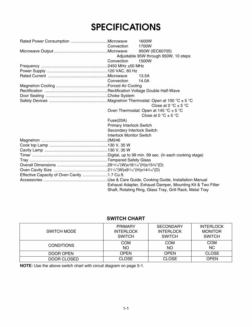
SPECIFICATIONSRated Power Consumption ................................Microwave 1600W
Convection 1700WMicrowave Output ...............................................Microwave 950W (IEC60705)
Adjustable 95W through 950W, 10 stepsConvection 1500W
Frequency ..........................................................2450 MHz ±50 MHzPower Supply .....................................................120 VAC, 60 HzRated Current ....................................................Microwave 13.5A
Convection 14.0AMagnetron Cooling .............................................Forced Air CoolingRectification .......................................................Rectification Voltage Double Half-WaveDoor Sealing ......................................................Choke SystemSafety Devices ...................................................Magnetron Thermostat: Open at 150 °C ± 5 °C
Close at 0 °C ± 5 °C............................................................................Oven Thermostat: Open at 145 °C ± 5 °C
Close at 0 °C ± 5 °C............................................................................Fuse(20A)............................................................................Primary Interlock Switch............................................................................Secondary Interlock Switch............................................................................Interlock Monitor SwitchMagnetron ..........................................................2M246Cook top Lamp ...................................................130 V, 35 WCavity Lamp .......................................................130 V, 35 WTimer ..................................................................Digital, up to 99 min. 99 sec. (in each cooking stage)Tray ....................................................................Tempered Safety GlassOverall Dimensions ............................................2915/16”(W)x167/16”(H)x153/8”(D)Oven Cavity Size ...............................................211/4”(W)x97/16”(H)x143/16”(D)Effective Capacity of Oven Cavity ......................1.7 Cu.ft.Accessories ........................................................Use & Care Guide, Cooking Guide, Installation Manual
Exhaust Adapter, Exhaust Damper, Mounting Kit & Two FilterShaft, Rotating Ring, Glass Tray, Grill Rack, Metal Tray
SWITCH CHART
SWITCH MODE
CONDITIONS
DOOR OPEN OPEN OPEN CLOSECLOSE CLOSE OPENDOOR CLOSED
PRIMARYINTERLOCK
SWITCH
SECONDARYINTERLOCK
SWITCH
INTERLOCKMONITORSWITCH
COMNO
COMNO
COMNC
NOTE: Use the above switch chart with circuit diagram on page 5-1.

2-1
CAUTIONSUnlike other appliances, the microwave oven ishigh-voltage and high-current equipment.Though it is free from danger in ordinary use,extreme care should be taken during repair.
MICROWAVE RADIATIONPersonnel should not be exposed to themicrowave energy which may radiate from themagnetron or other microwave generatingdevice if it is improperly used or connection.All input and output microwave connections,waveguide, flange, and gasket must be securenever operate the device without a microwaveenergy absorbing load attached.Never look into an open waveguide or antennawhile the device is energized.
• DO NOT operate on a 2-wire extension cord during repairand use.
• NEVER TOUCH any oven components or wiring duringoperation.
• BEFORE TOUCHING any parts of the oven, alwaysremove the power plug from the outlet.
• Remove your watches whenever working close to orreplacing the Magnetron.
• DO NOT touch any parts of the control panel circuit. Aresulting static electric discharge may damage this P.C.B.
• NEVER operate the oven with no load.• NEVER injure the door seal and front plate of the oven
cavity.• NEVER put iron tools on the magnetron.• NEVER put anything into the latch hole and the interlock
switches area.
• Proper operation of the microwave oven requires thatthe magnetron be assembled to the waveguide andcavity. Never operate the magnetron unless it is properly installed.
• Be sure that the magnetron gasket is properly installed around the dome of the tube wheneverinstalling the magnetron.
THE OVEN IS TO BE SERVICED ONLYBY PROPERLY QUALIFIED SERVICEPERSONNEL.
GasketANTENNA
COOLING FIN
MAGNETRONCHASSIS GROUND FILAMENT
TERMINALS
MAGNETRON

3-1
INSTALLATIONS
BEFORE YOU BEGIN, READ THE FOLLOWING INSTRUCTIONS COMPLETELY AND CAREFULLY.
PRECAUTIONS ON INSTALLATIONA. Plug the power supply cord into a 120V AC, 60Hz,
single-phase power source with a capacity of atleast 20 amperes.
B. Avoid placing the unit in a location where there isdirect heat or splashing water.
C. Install the unit on the mounting plate firmly.D. Place the unit as far away as possible from TV,
radio, etc. to prevent interference.
GROUNDING INSTRUCTIONSFor personal safety, this appliance must be fullygrounded at all times.
In the event of an electrical short circuit, groundingreduces the risk of electrical shock.The plug must be plugged into an outlet that isproperly installed and grounded.
CAUTIONThis unit is equipped with a 3-prong plug for yoursafety. If the wall outlet is a grounded 3-hole type,the unit will be grounded automatically.
WARNINGImproper use of the grounding plug can result in arisk of electric shock.Do not, under any circumstances, cut or remove thethird ground prong from the power cord plug.
Plug with GroundProng
Properly Polarizedand GroundedOutlet

4-1
OPERATING INSTRUCTIONSCONTROL PANEL

4-2
CONTROL PANEL INSTRUCTIONS1. DISPLAY: The Display includes a clock and indicators
to tell you time of day, cooking time settings, andcooking functions selected.
2. CUSTOM COOK: Touch this pad to recall one cookinginstruction previously programmed into memory.
3. CLOCK: Touch this pad to enter the time of day.
4. TIMER: Touch this pad to set the timer.
5. CUSTOM SET: Touch this pad to change the oven’sdefault settings for sound, clock, display speed, anddefrost weight.
6. SENSOR COOK: Touch this pad to cook bakedpotato, frozen vegetable, fresh vegetable, cannedvegetable, frozen entrée, and rice. The oven’s sensorwill tell the oven how long to cook depending on theamount of humidity coming from the food.
7. SENSOR REHEAT: Touch this pad to reheatcasserole, dinner plate, pizza slice, and soup/sauce.The oven’s sensor will tell the oven how long to cookdepending on the amount of humidity coming from thefood.
8. SENSOR POPCORN: Touch this pad when poppingpopcorn in your microwave oven. The oven’s sensorwill tell the oven how long to cook depending on theamount of humidity it detects from the popcorn.
9. AUTO DEFROST: Touch this pad to select food typeand defrost food by weight.
10. SPEED AUTO COMBI: Touch this pad when settingweight combination cooking.
11. AUTO COOK: Touch this pad to cook Bacon, FreshRoll & Muffin, Frozen Roll & Muffin, Beverage,Chicken Pieces, and Hot Cereal.
12. MICRO.: Touch this pad when setting Microwavecooking.
13. CONV.: Touch this pad when setting Convectioncooking.
14. COMBI.: Touch this pad when setting combinationcooking or preheat.
15. NUMBER: Touch number pads to enter cooking time,power level, quantities, weights, or cookingtemperature.
16. EZ-ON: Touch this pad to set and start at 100%power level on microwave cooking.
17. POWER LEVEL: Touch this pad to select a cookingpower level.
18. START/ENTER: Touch this pad to start a function orenter all entries. If you open the door after ovenbegins to cook, touch START/ENTER again.
19. STOP/CLEAR: Touch this pad to stop the oven or toclear all entries.
20. SOFTEN: Touch this pad to soften Butter, Ice Cream,Cream Cheese, or Frozen Juice.
21. MELT: Touch this pad to melt Butter or Margarine,Chocolate, Cheese, or Marshmallow.
22. More: Touch this pad to add ten seconds of cookingtime each time you press it.
23. Less: Touch this pad to subtract ten seconds ofcooking time each time you press it.
24. VENT ON/OFF: Touch this pad to turn the fan on/off.
25. VENT 5-SPEED: Touch this pad to choose one of 5fan speeds.
26. VENT AUTO TIME SET: Touch this pad when settingventilation time. (1, 3, 5, 10, and 30 minutes.)
27. LIGHT ON/OFF: Touch this pad to turn the cooktop/countertop light on or off.
28. TURNTABLE ON/OFF: Touch this pad to turn off theturntable. OFF will appear in the display.NOTE: This option is not available in sensor cook anddefrost modes.

5-1
OVERALL CIRCUIT DIAGRAMSCHEMATIC DIAGRAM

5-2
MATRIX CIRCUIT FOR TOUCH KEY BOARD
5-SPEED
LEVELPOWER
CUSTOM
POPCORN
SET
ON/OFF(VENT)
N.C
1
TIME SETAUTO
CLOCK
STOP/CLEAR
N.CENTERSTART/
ON/OFFLIGHT
ON/OFFTURNTABLE
REHEATCOOK
AUTOCOOK
(VENT)
AUTO
TIMER
DEFROST
N.C
8 9 0
AUTO
MORE
COMBI.
SPEED
SOFTEN
N.C
LESS
MELT
CONV.COOK
CUSTOMN.C
2 3
MICRO.
4
N.C
5 6
COMBI.
7
EZ-ON
12
13
11
10
8
9
1 2 3 4 5 6 7
KEY MATRIX

6-1
GENERAL INFORMATION FOR SERVICEGENERAL PRECAUTIONS IN USE
A. Never operate the unit when it is empty. Operating the oven with no load may shorten thelife of the magnetron. Whenever cooking dry foods(dried fish, bread, etc.)or a small amount of food, be sure to put a glass of water into the cookingcompartment. The glass turntable may become hotafter operating, be careful when touching it.
B. Aluminum foil should be avoided because it willdisrupt cooking and may cause arcing. However,small pieces may be used to cover some parts offood to slow the cooking. Any aluminum foil usedshould never be closer than 2.5 cm to any side wallof the oven.
TRIAL OPERATIONAfter installation, the following sequences and resultsshould be checked carefully.
A. Put a container filled with water (about 1 liter)intothe oven, and close the door tightly.
B. Set cooking time for 10 minutes by touching “1 ”and then “0” three times.“1, 0, 0, 0” appears in thedisplay window.
C. Touch the START/ENTER key. Make sure the cavity light comes on. The unit willbegin cooking and the display window will show thetime counting down by seconds.
D. After about 5 minutes, make sure the primaryinterlock switch, the secondary interlock switch andthe interlock monitor switch operate properly byopening and closing the door several times. Touchthe START/ENTER key each time the door isclosed.
E. Continue operating the unit. Two short and a longbeep sound signal is heard when the time is up.The unit will shut off automatically.
F. Confirm the water is hot. G. Finally, measure the output power according to
“POWER OUTPUT MEASUREMENT” on page 7-3.
FEATURES AND SPECIFICATIONSFEATURESA. The safety systems incorporated in this model are:
(1) Primary interlock switch(2) Secondary interlock switch(3) Interlock monitor switch(4) Choke system(5) Oven cavity thermostat
(Note This thermostat located on the oven cavitywill open and stop the unit from operation only ifa high temperature is reached, such as, a firecreated by overcooking food.)
B. Any one of 10 power output levels ranging 0W to950W can be selected by the touch control andelectronic computer system.
C. Cooking time can be displayed on the digitalreadout.
D. Three different cooking stages (Include Defrost)can be changes from one cooking stage to another.This is made possible with the memory function ofthe microprocessor.

7-1
SERVICE INFORMATION
PRELIMINARY
A. SINCE NEARLY 4000 VOLTS EXISTS IN SOMECIRCUITS OF THIS UNIT REPAIRS SHOULD BECARRIED OUT WITH GREAT CARE.The filament leads of magnetron carry HighVoltage with respect to ground. Extreme cautionmust be exercised. Never plug the unit into apower source to determine which component isdefective in high voltage section.
B. TO AVOID POSSIBLE EXPOSURE TOMICROWAVE ENERGY LEAKAGE, THEFOLLOWING PRECAUTIONS MUST BE TAKENBEFORE SERVICING.
(1) Before the power is applied:(a) Make sure the primary interlock switch, the
secondary interlock switch and the interlockmonitor switch operate properly by openingand closing the door several by opening andclosing the door several times.
(b) Make sure the perforated screen and thedielectric choke of the door are correctly andfirmly mounted.
(2) After power is applied:(a) Make sure the interlock switch mechanism
is operating properly by opening and closingthe door.
(b) Check microwave energy leakage must be belowthe limit of 5 mW/cm2 .(All service adjustments should be made forminimum microwave energy leakagereadings).
(3) Do not operate the unit until it is completelyrepaired, if any of the following conditions exist.The unit must not be operated.
(a) The door does not close firmly.(b) The hinge is broken.(c) The door seal is damaged.(d) The door is bent or warped, or there is any
other visible damage on the unit that maycause microwave energy leakage.
NOTE: Always keep the seal clean.(e) Make sure that there are no defective parts
in the interlock mechanism.(f) Make sure that there are no detective parts
in the microwave generating and transmissionassembly (especially waveguide).
(4) The following items should be checked after theunit is repaired:
(a) The interlock monitor switch is connectedcorrectly and firmly.
(b) The magnetron gasket is properly positionedand mounted.
(c) The waveguide and the oven cavity are intact.(no microwave energy leakage)
(d) The door can be properly closed and thesafety switches work properly.
(e) The unit must stop when the door is opened orthe time is up.
The unit must not be operated with any of the abovecomponents removed or by-passed.
PRECAUTIONS AND REPAIR SERVICE TIPS
7-2
MICROWAVE LEAKAGE TEST
CAUTIONS
• Be sure to check microwave leakage prior toservicing the oven if the oven is operative prior toservicing.
• The service personnel should inform themanufacture importer, or assembler of any certifiedoven unit found to have a microwave emission levelin excess of 5 mW/cm2 and should repair any unitfound to have excessive emission levels at no cost tothe owner and should ascertain the cause of theexcessive leakage. The service personnel shouldinstruct the owner not to use the unit until the oven hasbeen brought into compliance.
• If the oven operates with the door open, the servicepersonnel should;
- Tell the user not to operate the oven- Contact the manufacturer and CDRH (Center for
Devices and Radiological Health)immediately.NOTE: Address on CDRH
Office of Compliance (HFZ-312)Center for Devices and Radiological Health1390 Piccard Drive Rockville, Maryland 20850
• The service personnel should check all surface andvent openings for microwave emission testing.
• Check for microwave energy leakage after everyservicing. The power density of the microwaveradiation leakage emitted by the microwave ovenshould not exceed 1mW/cm2.sq. And always startmeasuring of an unknown field to assure safety foroperating personnel from radiation leakage.NOTE: The standard is 5mW/cm2.sq. while in thecustomer’s home.1mW/cm2.sq.stated here ismanufacturer’s own voluntary standard for units incustomer ’s home.
EQUIPMENT-
• TESTER ((VOLTS-DC, AC, Ohmmeter)• Microwave survey meter- Holaday HI-1500
HI-1501- Narda 8100
8200• 600 cc non conductive material beaker (glass or
plastic), inside diameter:approx.8.5 cm (31/2 in.)• Glass thermometer: 100 °C or 212 °F (1 deg scale)
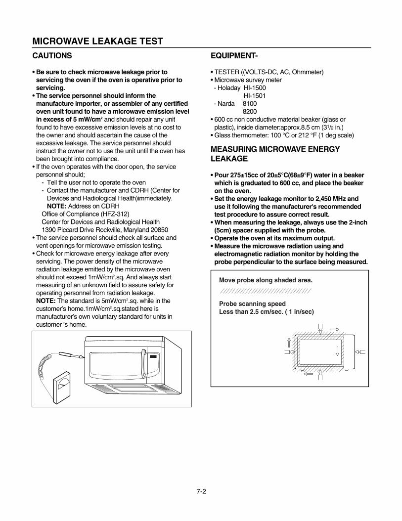
MEASURING MICROWAVE ENERGYLEAKAGE
• Pour 275±15cc of 20±5°C(68±9°F) water in a beakerwhich is graduated to 600 cc, and place the beakeron the oven.
• Set the energy leakage monitor to 2,450 MHz anduse it following the manufacturer's recommendedtest procedure to assure correct result.
• When measuring the leakage, always use the 2-inch(5cm) spacer supplied with the probe.
• Operate the oven at its maximum output.• Measure the microwave radiation using and
electromagnetic radiation monitor by holding theprobe perpendicular to the surface being measured.
Move probe along shaded area.
Probe scanning speedLess than 2.5 cm/sec. ( 1 in/sec)

7-3
MEASUREMENT WITH THE OUTSIDE CASEREMOVED(1) When you replace the magnetron, measure for
microwave energy leakage before the outer caseis installed and after all necessary componentsare replaced or adjusted. Special care should betaken in measuring the following parts.-Around the magnetron-The waveguide
WARNING: AVOID CONTACTING ANY HIGHVOLTAGE PARTS.
MEASUREMENT WITH A FULLYASSEMBLED OVEN(1) After all components, including the outer
panels, are fully assembled, measure formicrowave energy leakage around the doorviewing window, the exhaust opening and airinlet openings.
(2) Microwave energy leakage must not exceed thevalues prescribed below. NOTES:Leakage with the outer panels removed -lessthan 5 mW/cm2. Leakage for a fully assembled oven (“Before thelatch switch (primary)is interrupted”)with the doorin a slightly opened position -less than 1 mW/cm2
NOTE WHEN MEASURING(1) Do not exceed meter full scale deflection. (2) The test probe must be removed no faster than
1 inch/sec (2.5cm/sec)along the shaded area,otherwise a false reading may result.
(3) The test probe must be held with the grip portionof the handle. A false reading may result if theoperator ’s hand is between the handle and theprobe.
(4) When testing near a corner of the door, keepthe probe perpendicular to the surface makingsure the probe is moved horizontally along theoven surface.
RECORD KEEPING AND NOTIFICATIONAFTER MEASUREMENT(1) After adjustment and repair of any microwave
energy interruption or microwave energy blockingdevice, record the measured values for futurereference. Also enter the information on theservice invoice.
(2) Should the microwave energy leakage not bemore than 1 mW/cm2 after determining that allparts are in good condition, functioning properlyand genuine replacement parts which are listed inthis manual have been used.
(3) At least once a year, have the electromagneticenergy leakage monitor checked for calibrationby its manufacturer.
POWER OUTPUT MEASUREMENT(1) Microwave power output measurement is made
with the microwave oven supplied at its rated voltage andoperated at its maximum microwave power setting with aload of (1000 ± 5)g of potable water.
(2) The water is contained in a cylindrical borosilicateglass vessel having a maximum material thicknessof 1/8” (3 mm)and an outside diameter of approximately7.6” (190mm).
(3) The oven and the empty vessel are at ambientTemperature(T0)prior to the start of the test.
(4) The initial temperature (T1)of the water is(10 ± 1)°C (50 °F)It is measured immediately before thewater is added to the vessel. After addition of the water tothe vessel, the load is immediately placed on the centerof the turntable which is in the lowest position and themicrowave power switched on.
(5) The time t for the temperature of the water to riseby a value T of (10 ± 1)°K is measured, where t is thetime in seconds and T is the temperature rise.The initial and final water temperatures are selected sothat the maximum difference between the final watertemperature and the ambient temperature is 5 °K.
(6) The microwave power output P in watts is calculatedfrom the following formula :
4.187 Mw(T2 –T1)+0.55Mc(T2 –T0)t
is measured while the microwave generator isoperating at full power. Magnetron filament heat-uptime is not included. (about 3 sec)
(7) The water is stirred to equalize temperaturethroughout the vessel, prior to measuring the finalwater temperature.
(8) Stirring devices and measuring instruments areselected in order to minimize addition or removal ofheat.
P =
WhereP is the microwave power output, in watts:Mw is the mass of the water, in grams:Mc is the mass of the container, in grams:T0 is the ambient temperature, in °C:T1 is the initial temperature of the water, in °C:T2 is the final temperature of the water, in °C:t is the heating time in seconds, excluding the magnetron filament heat-up time.
WATER LOAD
GLASS TRAY

IMPORTANT NOTES:
UNIT MUST BE DISCONNECTED FROM ELEC-TRICAL OUTLET WHEN MAKING REPAIRS, RE-PLACEMENTS, ADJUSTMENTS AND CONTIN-UITY CHECKS. WAIT AT LEAST ONE MINUTE,UNTIL THE HIGH VOLTAGE CAPACITOR IN THEHIGH VOLTAGE POWER SUPPLY HAS FULLYDISCHARGED.THE CAPACITOR SHOULD BE DISCHARGED BYUSING INSULATED WIRE - I.E. TEST PROBECONNECTED TO 10K-OHM RESISTOR IN SERIESTO GROUND.WHEN RECONNECTING THE WIRE LEADS TOANY PART, MAKE SURE THE WIRING CONNE-CTIONS AND LEAD COLORS ARE CORRECTLYMATCHED ACCORDING TO THE OVERALL CIR-CUIT DIAGRAM. (ESPECIALLY SWITCHES ANDHIGH VOLTAGE CIRCUIT.)
A. REMOVING POWER AND CONTROLCIRCUIT BOARD (Figures 1, 2 and 3)
(1) Remove a screw securing the control panelassembly to the oven cavity.
(2) Remove the control panel with pushing it upward.(3) Remove the five connectors (CN1, CN2, CN4,
CN5) and wire leads (Relay8, Relay10) from thecircuit board.
(4) Remove 4 screws securing the circuit board.
Circuit Board
7-4
DISASSEMBLY INSTRUCTIONS
Power Transformer
Control Panel
Screw
Circuit Board
(CN2)
(RY8)
(RY10)
(CN1)
(CN5)
(CN4)
(CN6)
Control Bracket
Circuit Board
FPC Connector(S1)
(5) Remove the FPC connector from the terminalsocket following “HOW TO REMOVE THE FPCCONNECTOR” on the next page.
(6) Remove the circuit board from the control bracketcarefully.
Figure 1
Figure 2
Figure 3

7-5
HOW TO REMOVE THE F.P.C. CONNECTOR
Follow the steps below as illustrated in Figures 4and 5 to remove the F.P.C. connector.
(1) Hold the edges of the plastic fastener withthumb and forefinger.(Figure 4)
(2) Lift up the lever of the plastic fastener fromthe terminal socket by lightly pressing thelever end with forefinger.(Figure 5)
(3) Remove the F.P.C. connector from theterminal socket.
HOW TO INSERT THE F.P.C. CONNECTOR
Follow the steps below as illustrated in Figures 6and 7 to insert the F.P.C. connector.(1) Insert the F.P.C. connector into the terminal
socket securely with the fingers.(2) Hold the plastic fastener with thumb and
forefinger of the other hand, and push itslowly into the terminal socket. (Figure 6)NOTE: When reconnecting the F.P.C.
connector make sure that the holeson the F.P.C. connector are properlyengaged with the hooks on the plasticfastener
(3) Lock the level of the plastic fastener into thehook of the terminal socket securely byreleasing the fingers.(Figure 7)
Figure 4
Figure 6
Figure 7
Figure 5
F.P.C.Connector
Terminalsocket
Plastic fastener
Holes
Hook
Plastic fastener
Terminalsocket
F.P.C.Connector
Plasticfastener
Terminalsocket
F.P.C.Connector
Terminalsocket
Plastic fastener
Holes
Hook
7-6
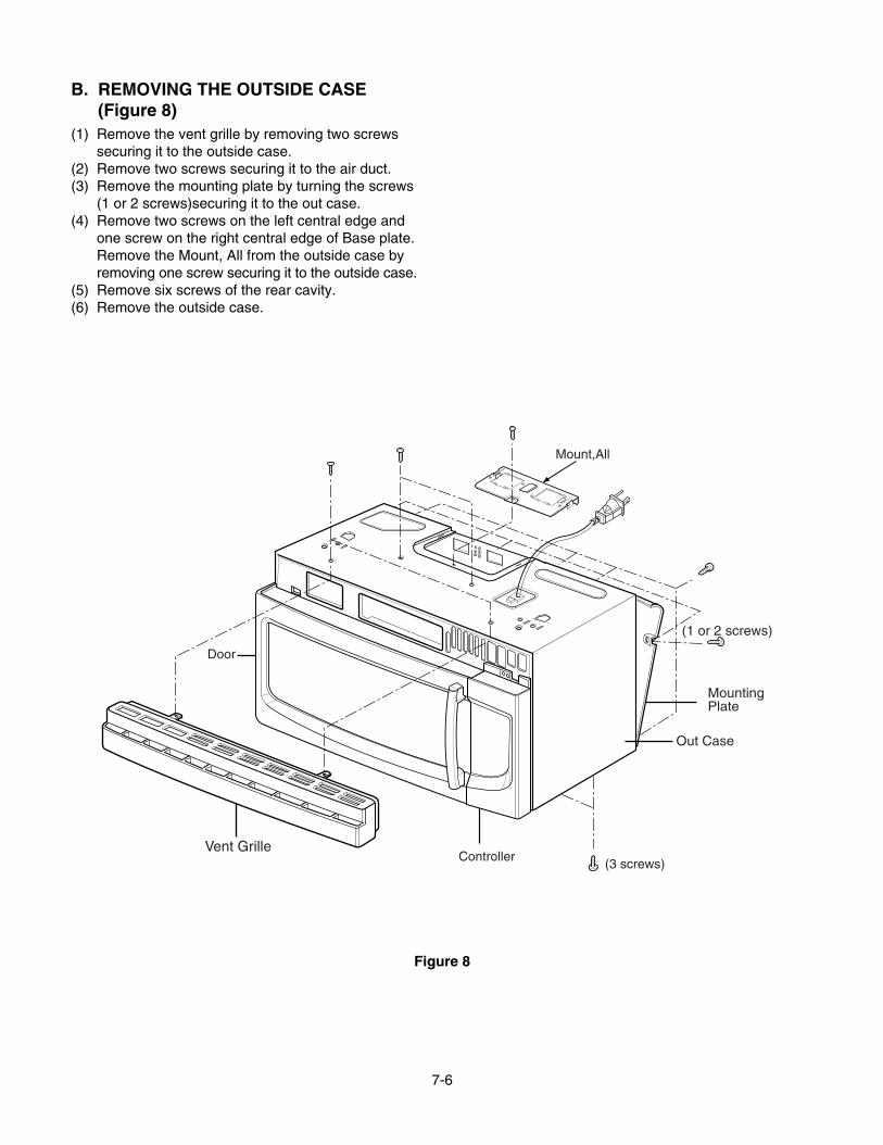
B. REMOVING THE OUTSIDE CASE(Figure 8)
(1) Remove the vent grille by removing two screwssecuring it to the outside case.
(2) Remove two screws securing it to the air duct.(3) Remove the mounting plate by turning the screws
(1 or 2 screws)securing it to the out case.(4) Remove two screws on the left central edge and
one screw on the right central edge of Base plate.Remove the Mount, All from the outside case byremoving one screw securing it to the outside case.
(5) Remove six screws of the rear cavity.(6) Remove the outside case.
Controller(3 screws)
Door
MountingPlate
(1 or 2 screws)
Out Case
Mount,All
Vent Grille
Figure 8

7-7
C. REMOVING THE DOOR INTERLOCKSWITCHES (Figures 9, 10)
(1) Disconnect the wire leads from the interlockswitches.
(2) Remove two screws securing the Latch Board.(3) Make necessary replacements and check
microwave energy leakage according to“ADJUSTMENT PROCEDURES” on page 7-12.
Latch Board
Primary Interlock Switch
Monitor Interlock Switch
Secondary Interlock Switch
Latch Board
PrimaryInterlock Switch
Monitor Interlock Switch
SecondaryInterlock Switch
Figure 9
Figure 10

7-8
D. REMOVING MAGNETRON(Figures 11 Through 13b)
(1) Remove the vent grille by loosening two screws.(Figure 11)
(2) Remove the outside case. See page 7-6.(3) Remove four tap tite screws securing the
magnetron to the wave guide.(4) Disconnect the leadwire.(5) Remove the magnetron VERY CAREFULLY.
NOTES:• When removing the magnetron, make sure that its
dome does not hit any adjacent parts, or it may bedamaged.
• When replacing the magnetron, be sure to install themagnetron gasket in the correct position and be surethat the gasket is in good condition.
• After replacing the magnetron, check for microwaveenergy leakage with a survey meter Checkmicrowave energy leakage must be below the limitof 5 mW/cm2. (All service adjustments should bemade for minimum microwave energy leakagereadings.)
Figure 11
Figure 13-a Figure 13-b
Controller(3 screws)
Door
MountingPlate
(1 or 2 screws)
Out Case
Mount,All
Vent Grille
Figure 12
7-9
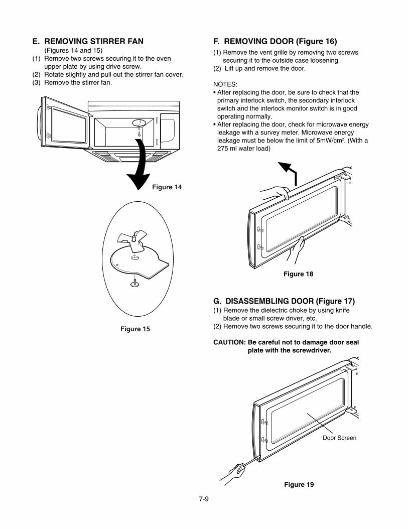
E. REMOVING STIRRER FAN(Figures 14 and 15)
(1) Remove two screws securing it to the ovenupper plate by using drive screw.
(2) Rotate slightly and pull out the stirrer fan cover.(3) Remove the stirrer fan.
F. REMOVING DOOR (Figure 16)(1) Remove the vent grille by removing two screws
securing it to the outside case loosening.(2) Lift up and remove the door.
NOTES:• After replacing the door, be sure to check that the
primary interlock switch, the secondary interlockswitch and the interlock monitor switch is in goodoperating normally.
• After replacing the door, check for microwave energyleakage with a survey meter. Microwave energyleakage must be below the limit of 5mW/cm2. (With a275 ml water load)
G. DISASSEMBLING DOOR (Figure 17)(1) Remove the dielectric choke by using knife
blade or small screw driver, etc.(2) Remove two screws securing it to the door handle.
CAUTION: Be careful not to damage door sealplate with the screwdriver.
Figure 15
Figure 14
Figure 18
Door Screen
Figure 19
7-10
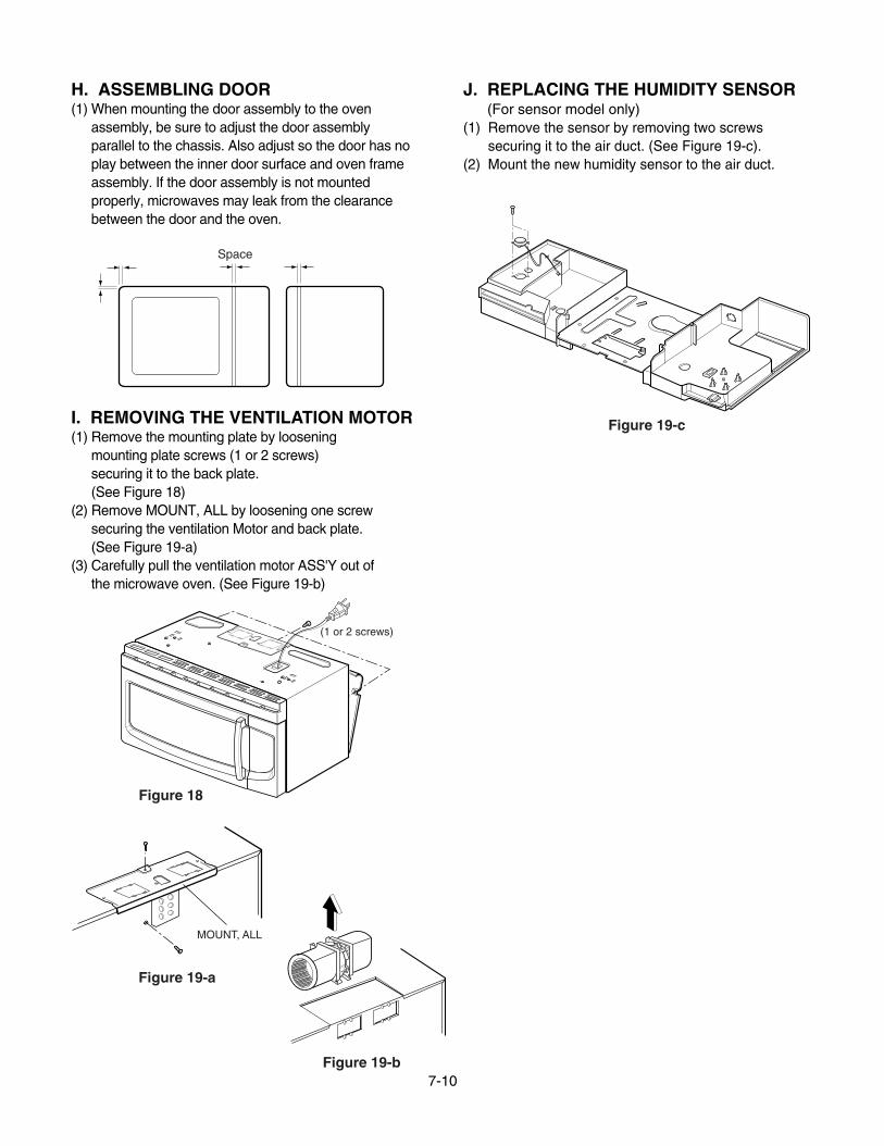
H. ASSEMBLING DOOR(1) When mounting the door assembly to the oven
assembly, be sure to adjust the door assemblyparallel to the chassis. Also adjust so the door has noplay between the inner door surface and oven frameassembly. If the door assembly is not mountedproperly, microwaves may leak from the clearancebetween the door and the oven.
I. REMOVING THE VENTILATION MOTOR(1) Remove the mounting plate by loosening
mounting plate screws (1 or 2 screws)securing it to the back plate.(See Figure 18)
(2) Remove MOUNT, ALL by loosening one screwsecuring the ventilation Motor and back plate. (See Figure 19-a)
(3) Carefully pull the ventilation motor ASS'Y out ofthe microwave oven. (See Figure 19-b)
J. REPLACING THE HUMIDITY SENSOR(For sensor model only)
(1) Remove the sensor by removing two screwssecuring it to the air duct. (See Figure 19-c).
(2) Mount the new humidity sensor to the air duct.
Space
Figure 19-c
(1 or 2 screws)
MOUNT, ALL
Figure 18
Figure 19-a
Figure 19-b

7-11
K. REMOVING THE TURNTABLE MOTOR(1) Remove the turntable.(2) Remove the turntable shaft VERY CAREFULLY
with a slotted screwdriver. (Figure 21)(3) Remove the base plate by removing 7 screws
securing it to the oven cavity. (Figure 22-a)(4) Disconnect the leadwire from the turntable motor
terminals.(5) Remove the 2 screws securing the turntable motor
to the oven cavity ASS'Y. (Figure 22-b)
NOTES:• Remove the leadwire from the turntable motor
VERY CAREFULLY.• Be sure to grasp the connector not the wires when
removing.
L. REMOVING CONVECTION HEATERAND THERMISTOR (Figure 23)
(1) Remove the out case.(2) Remove the air duct by removing six screws
securing it to the oven front plate, guide air andglasswool-L cover.
(3) Disconnect the wire leads of air duct.(4) Remove the magnetron.(5) Remove the latch board assembly.(6) Remove the bottom plate by removing four screws.(7) Remove the four net screws securing chamber
assembly.(8) Lift the chamber assembly from the oven cavity.(9) Remove three screws securing the heater of the
chamber assembly.(10) Lift the convection heater from the chamber
assembly.
Wire Leads
Turntable Motor
Figure 22-b
Figure 20
Figure 23
Figure 21-a

7-12
INTERLOCK MECHANISMThe door lock mechanism is a device which has been specially designed to eliminate microwave activity when thedoor is opened during cooking and thus to prevent the danger resulting from the microwave leakage.
ADJUSTMENT PROCEDURESTo avoid possible exposure to microwave energy
leakage, adjust the door latches and interlockswitches, using the following procedure.
The Interlock Monitor and Primary Interlock Switch actas the final safety switch protecting the user frommicrowave energy. The terminals between “COM” and“NC” of the Interlock Monitor must close when the dooris opened. After adjusting the Interlock Monitor Switch, make sure that it is correctly connected.Mounting of the primary/monitor/secondary switches tothe latch board.
CHECK THE DOOR LATCH AND SWITCHCLOSING.
NOTE:The outer cover of the microwave oven isremoved.
(1) Set the microwave oven on its side so that you cansee the latch board and the switches, as shown inFigure 23-a.
(2) Close the door tightly and check gaps A and B tobe sure they are no more than 1/64” (0.5 mm).See Figure 23-b for close-up view of gaps A and B(door latches). If all gaps are less than 1/64”(0.5 mm), adjustment of the latch board may notbe necessary. Go to Steps 5 and 6 to check thesequence of the switches.
NOTE:If any gap is larger than 1/64” (0.5 mm), you willneed to adjust the latch board”. Go to step 3and follow all steps in order.
ADJUST THE LATCH AND SWITCH CLOSING
(3) Loosen the two screws holding the plastic latchboard as shown.
(4) With the oven door closed tightly, move the latchboard upward toward the top of the oven and/oraway from the door latch until the gaps are lessthan 1/64 ” (0.5 mm).Hold the latch board tightly in this position until youcheck the sequence of the switches in steps 5and 6.
INTERLOCK SYSTEM
InterlockMonitor Switch
LATCH
LATCH BOARD
0-1/64"
0-1/64"
Latch Board
PrimaryInterlock Switch
SecondaryInterlock Switch
Figure 23-a
Figure 23-b

7-13
TEST THE LATCH AND SWITCH SEQUENCE
(5) Open the oven door slowly. Watch the door latch,the Secondary Switch. Release Rod and Leveron the switches to make sure they are zero to thebody of the switches in the following sequence:
-Primary Interlock Switch-Secondary Interlock Switch-Interlock Monitor Switch
Adjust the latch board until the switches operate inthis sequence. See Steps 3 and 4.
(6) Close the oven door slowly and be sure it is tightlyclosed. Watch the three switches to make surethey are zero to the body of the switches in thefollowing sequence:
-Interlock Monitor Switch-Primary Interlock Switch-Secondary Interlock Switch
NOTE: The Interlock Monitor Switch is an addedsafety check on the Primary andSecondary Interlock Switches. If thePrimary and Secondary Interlock Switchesallow the oven to operate with the dooropen, the Monitor Switch will blow thefuse.
(7) When you achieve the proper sequence ofswitches in Steps 5 and 6, tighten the latch boardscrews at that point.
TEST THE MICROWAVE ENERGY LEAKAGE
Make sure the microwave energy leakage is below thelimit of 1mW/cm2 (with a 275 ml water load) and5mW/cm2 (with a 275 ml water load without thecabinet) when measured with a survey meter.

7-14
A. PRIMARY INTERLOCK SWITCH TEST
When the door is opened slowly, an audible clickshould be heard at the same time or successivelyat intervals and the latches should activate theswitches with an audible clickIf the latches do not activate the switches when thedoor is closed, the switches should be a adjustedin accordance with the adjustment procedure.Disconnect the wire lead from the primary switch.Connect the ohmmeter leads to the common(COM)and normally open (NO)terminal of theswitch. The meter should indicate an open circuitin the door open condition.When the door is closed, the meter should indicatea closed circuit.When the primary switch operation is abnormal, make the necessary adjustment or replace theswitch only with the same type of switch.
B. SECONDARY INTERLOCK SWITCH TEST
Disconnect the wire lead from the secondaryswitch.Connect the ohmmeter leads to the common(COM)and normally open (NO)terminals of theswitch. The meter should indicate a open circuit inthe door open condition. When the door is closed,meter should indicate an closed circuit. When thesecondary switch operation is abnormal, make thenecessary adjustment or replace the switch onlywith the same type of switch.
C. MONITOR SWITCH TESTDisconnect the wire lead from the monitor switch.Connect the ohmmeter leads to the common(COM)and normally closed (NC)terminals of theswitch. The meter should indicate closed circuit inthe door open condition. When the door is closed, meter should indicate an open circuit. When themonitor switch operation is abnormal, replace withthe same type of switch.NOTE: After repairing the door or the interlocksystem, it is necessary to do this continuitytest before operating the oven.
INTERLOCK CONTINUITY TEST
COMPONENTS TEST PROCEDURE RESULTS
SWITCHES Check for continuity of the Door Door(Wire leads removed) switch with an Ohm-meter open closed
PrimarySwitch
MonitorSwitch
SecondarySwitch
NOTE : After checking for the continuity of switches, make sure that they areconnected correctly.
WARNING : FOR CONTINUED PROTECTION AGAINST EXCESSIVE RADIATIONEMISSION, REPLACE ONLY WITH IDENTICAL REPLACEMENT PARTS.
TYPE NO.SZM-V16-FA-63 OR VP-533A-OF OR V-5230Q FOR PRIMARY SWITCHTYPE NO.SZM-V16-FA-62 OR VP-532A-OF OR V-5220Q FOR MONITOR SWITCHTYPE NO.SZM-V16-FA-63 OR VP-533A-OF OR V-5230Q FOR SECONDARY SWITCH
NOCOM
NC
COM
NOCOM

7-15
TEST AND CHECKOUT PRECEDURES AND TROUBLESHOOTING
CAUTIONS1. DISCONNECT THE POWER SUPPLY CORD FROM THE OUTLET WHENEVER REMOVING THE OUTER CASE
FROM THE UNIT. PROCEED WITH THE TEST ONLY AFTER DISCHARGING THE HIGH VOLTAGE CAPACITORAND REMOVING THE LEAD WIRES FROM THE PRIMARY WINDING OF THE HIGH VOLTAGE TRANSFORMER.
2. ALL OPERATIONAL CHECKS WITH MICROWAVE ENERGY MUST BE DONE WITH A LOAD (1 LITER OFWATER IN CONTAINER)IN THE OVEN.
A. TEST PROCEDURES
TRANSFORMER
MAGNETRON
1. Remove wire leads.2. Measure resistance. (ohm meter scale: Rx1)
• Primary winding • Secondary winding• Filament winding
3. Measure resistance. (ohm meter scale: Rx1000)• Primary winding to ground• Filament winding to ground
1. Remove wire leads. Install the magnetron sealin the correct position. Check that the seal is ingood condition.
2. Measure resistance. (ohm meter scale: Rx1)• Filament terminal
3. Measure resistance. (ohm meter scale: Rx1000)• Filament to chassis
Normal: Less than 1 ohm
Normal: Infinite
COMPONENTS TEST RESULTS
SECONDARYWINDING
PRIMARYWINDING
FILAMENTWINDING
Approx. 0.3 to 0.5 ohms Approx. 65 to 120 ohms 0 ohm
Normal: Infinite Normal: Infinite
Antenna Gasket
Chassis

7-16
COMPONENTS TEST RESULTS
Normal:Momently indicatesseveral ohm, and thengradually returns to infiniteNormal: Infinite.
Normal:Continuity.Abnormal: Infinite.
Normal: Infinite.Abnormal: Continuity.
1. Remove wire leads.2. Measure resistance.
(ohm meter scale: Rx1000)• Terminal to terminal
• Terminal to case
1. Measure continuity. Forward.(ohm meter scale: Rx1000)
2. Measure continuity. Reverse.(ohm meter scale: Rx1000)
CAPACITOR
DIODESome inexpensive metersmay indicate infiniteresistance in both directions.
1. Measure continuity.(ohm meter scale: Rx1)
2. Remove the lead wires and operate oven atpower level 1 through power level 10.
1. Measure continuity.(ohm meter scale: Rx1)
2. Remove the lead wires and operateoven at Convection Cooking.
1. Remove wire leads.2. Measure resistance.
(ohm meter scale: Rx1)
RELAY 8 PowerLevel
12345678910
4 Sec6 Sec8 Sec10 Sec12 Sec14 Sec16 Sec18 Sec20 Sec22 Sec
18 Sec16 Sec14 Sec12 Sec10 Sec8 Sec6 Sec4 Sec2 Sec0 Sec
RELAY 10Convection
Cooking StartOFF
Normal:Approximately
ohmAbnormal:Infinite or several.
FAN MOTORCIRCULATION MOTOR
Fan Cir
35-55 ohm 25-40 ohm

7-17
Normal:Approximately25 to 45 ohm
Normal:Approximately
Abnormal:Infinite or several.
Normal:Approximately 250 to 350Kohm at 68 ± 35°FAbnormal:Infinite or several.
Normal: Approximately
Abnormal:Infinite or several.
Normal: Approximately
at 68 ± 35°FAbnormal:Infinite or several.
COMPONENTS TEST RESULTS
VENTILATION MOTOR
123
DAMPER MOTOR (D.M)TURNTABLE MOTOR (T.M)STIRRER MOTOR (S.M)
THERMISTOR
HEATER ELEMENT
SENSOR
1. Remove wire leads.2. Measure resistance.
(ohm meter scale: Rx1)
1. Remove wire leads.2. Measure resistance.
(ohm meter scale: Rx1000)
1. Remove the connector from PCB2. Measure resistance across pins 1 & 3.
(ohm meter scale: Rx1)
1. Remove wire leads.2. Measure resistance.
(ohm meter scale:Rx1)
1. Remove the 3 pin connector from PCB.2. Measure resistance across pins 1 & 2.3. Across pins 2 & 3.
(ohm meter scale:Rx1)
D.M T.M S.M
2.3-3.5 2.6-3.5 100-170Kohm Kohm ohm
Conv. HTR
15-25
1 & 2 2 & 3
3.1 Kohm ∞

7-18
COMPONENTS TEST RESULTS
Measure the resistance between terminalpins of KEY CONNECTOR.NOTE:When reconnecting the FPC connector,make sure that the holes on the FPCconnector are properly engaged with hookson the plastic fastener.
MATRIX CIRCUIT FORTOUCH KEY BOARD
CONNECTOR(KEY CON)
TOUCH KEY BOARD
Resistancevalue
Whentouched
Less than400 ohms
When nottouched
More than1 mega ohm
FPC CONNECTORTop
1 2345678910111213
NOTES:• A MICROWAVE ENERGY TEST MUST ALWAYS BE PERFORMED WHEN THE UNIT IS SERVICED FOR
ANY REASON.• MAKE SURE THE WIRE LEADS ARE IN THE CORRECT POSITION.• WHEN REMOVING THE WIRE LEADS FROM THE PARTS, BE SURE TO GRASP THE CONNECTOR, NOT
THE WIRES.
5-SPEED
LEVELPOWER
CUSTOM
POPCORN
SET
ON/OFF(VENT)
N.C
1
TIME SETAUTO
CLOCK
STOP/CLEAR
N.CENTERSTART/
ON/OFFLIGHT
ON/OFFTURNTABLE
REHEATCOOK
AUTOCOOK
(VENT)
AUTO
TIMER
DEFROST
N.C
8 9 0
AUTO
MORE
COMBI.
SPEED
SOFTEN
N.C
LESS
MELT
CONV.COOK
CUSTOMN.C
2 3
MICRO.
4
N.C
5 6
COMBI.
7
EZ-ON
12
13
11
10
8
9
1 2 3 4 5 6 7

7-20
B. CHECKOUT PROCEDURES(1) CHECKOUT PROCEDURES FOR FUSE BLOWING
CAUTION: REPLACE BLOWN FUSE WITH 20 AMPERE FUSE.
NOTES:• If the fuse is blown by an improper switch operation, replace all switches and the fuse at the same time.
After replacing the defective switches with new ones, make sure that they are correctly connected.• Check for microwave energy leakage according to INTERLOCK ADJUSTMENT PROCEDURES on page
7-12 when the primary interlock, secondary interlock switches and/or the interlock monitor switches areadjusted or replaced.
Fuse blows immediately afterthe door is closed.
Fuse blows immediately afterthe door is opened.
Fuse blows when the door is closed andSTART/ENTER key is touched.
Improper operation of the primary interlock, secondaryinterlock switches and/or the interlock monitor switch.
Malfunction of the high voltage transformer; the highvoltage capacitor including the diode, the magnetron,the blower motor or the circuit board.
PROBLEMS CAUSES

7-21
(2)CHECKOUT PROCEDURES FOR RELAY.
-PROBLEM (A)-FAN motor turns on without touching START/ENTER
key when the door is closed.
-PROBLEM (B)-FAN motor turns on When the door is closed and
START/ENTER key is touched.
GOODRemove the mate connector of I/OCON from the circuit board.Does the unit still operate?
DefectiveWire Assembly
Replace thecircuit board
ReplaceWire Assembly
NO
NO
YES
YES
-PROBLEM (A)--Oven lamp turns on without touching START/ENTER
key when the door is closed.
GOODRemove the mate connector of I/OCON from the circuit board.Does the unit still operate?
DefectiveWire Assembly
Replace thecircuit board
ReplaceWire Assembly
NO
NO
YES
YES
GOODMeasure the voltage at pin NO.1,10 of CN1Voltage reading:120 V AC
Replace thecircuit board
DefectiveFAN motor
YES
NO
NO
YES
ReplaceFAN motor.
-PROBLEM (B)-Oven lamp turns on When the door is closed and
START/ENTER key is touched.
GOODMeasure the voltage at pin NO.1,10 of CN1Voltage reading:120 V AC
Replace thecircuit board
DefectiveOven lamp
YES
NO
NO
YES
ReplaceOven lamp

7-22
(3) CHECKOUT PROCEDURES FOR CIRCUITBOARDThe following symptoms indicate a defective circuitboard.
1) The start function fails to operate but the highvoltage Systems, the interlock switches, the doorsensing and the relay check good.
2) The unit with a normal relay continuously operates.3) Proper temperature measurement is not obtained.4) The buzzer does not sound or continues to sound.5) Some segments of one or more digits do not light
up, or they continue to light up, or segments lightwhen they should not.
6) Wrong figures appear.7) The figures of all digits.8) Some of the indicators do no flicker light up.9) The clock does not keep time properly.
NOTE: A MICROWAVE ENERGY LEAKAGE TEST MUST ALWAYS BE PERFORMED WHEN THE UNIT ISSERVICED FOR ANY REASON.

7-23
C. TROUBLE SHOOTING
WHEN YOU GET A COMPLAINT FROM YOUR CUSTOMER, EVALUATE THE COMPLAINT CAREFULLY. IF THEFOLLOWING SYMPTOMS APPLY, PLEASE INSTRUCT THE CUSTOMER IN THE PROPER USE OF THE TOASTER ANDMICROWAVE OVEN. THIS CAN ELIMINATE AN UNNECESSARY SERVICE CALL.
CAUTIONS1. Check grounding and cool this unit before checking for trouble.2. Be careful of the high voltage circuit.3. Discharge the high voltage capacitor.4. When checking the continuity of the switches or of the high voltage transformer, disconnect one lead wire from these
parts and then check continuity with the AC plug removed. To do otherwise may result in a false reading or damageto your meter.
5. Do not touch any part of the circuit on the PCB since static electric discharge may damage this control panel.Always touch yourself to ground while working on this panel to discharge any static charge built up in your body.(Micom model only)
CONDITION
Microwave oven does not work.
Inserting many plugs into oneoutlet and using them at thesame time.(blown fuse or breaker)
Plug is not inserted tightly.
Output power is too low. Low AC input voltage.
Food temperature is too low.
Using metallic ware andallowing it to touch the ovenwall.
Sparks occur in oven.
Inconsistent intensity ofmicrowave by theircharacteristics.
1. Use plastic wrap or lid.2. Stir once or twice while
cooking soup, cocoa ormilk, etc.
Uneven microwave cooking.
Ceramic ware trimmed ingold or silver powder is used.
Avoid using other electricalappliances when you use thisunit.
Insert plug securely.
Use the microwave oven atadequate line voltage.
This may not be a defect.It is possible that the foodshould be cooked for alonger time period.
Do not use metallic ware forcooking except where notedin the cooking guide.
Do not use any type ofcookware with metallictrimming.
CAUSE REMEDY
7-24
CONDITION CHECK RESULT CAUSE REMEDY
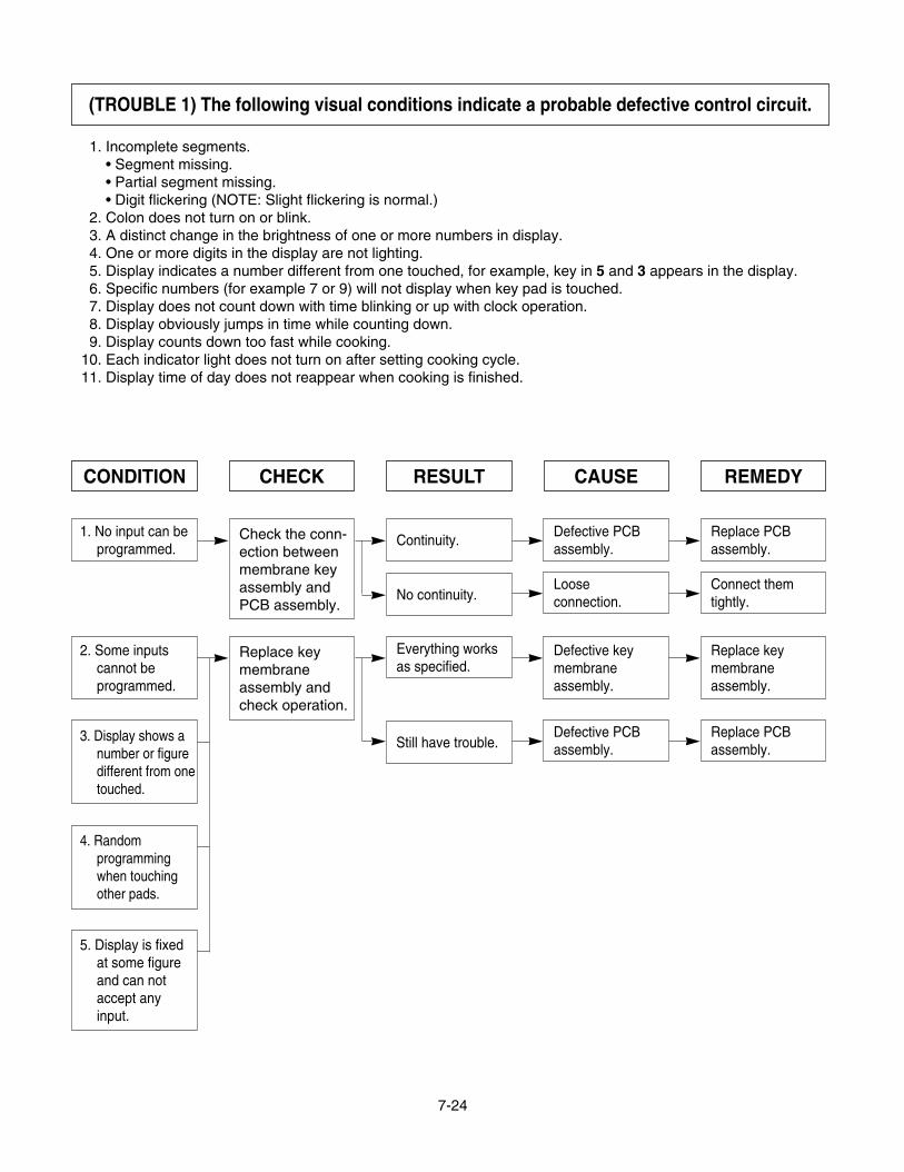
1. No input can beprogrammed.
Continuity.
No continuity.
Defective PCBassembly.
Replace PCBassembly.
Check the conn-ection betweenmembrane keyassembly andPCB assembly.
Looseconnection.
Connect themtightly.
2. Some inputscannot beprogrammed.
Everything worksas specified.
Still have trouble.
Defective keymembraneassembly.
Replace keymembraneassembly.
Replace keymembraneassembly andcheck operation.
3. Display shows anumber or figuredifferent from onetouched.
4. Randomprogrammingwhen touchingother pads.
5. Display is fixedat some figureand can notaccept anyinput.
Defective PCBassembly.
Replace PCBassembly.
(TROUBLE 1) The following visual conditions indicate a probable defective control circuit.
1. Incomplete segments.• Segment missing.• Partial segment missing.• Digit flickering (NOTE: Slight flickering is normal.)
2. Colon does not turn on or blink.3. A distinct change in the brightness of one or more numbers in display.4. One or more digits in the display are not lighting.5. Display indicates a number different from one touched, for example, key in 5 and 3 appears in the display.6. Specific numbers (for example 7 or 9) will not display when key pad is touched.7. Display does not count down with time blinking or up with clock operation.8. Display obviously jumps in time while counting down.9. Display counts down too fast while cooking.
10. Each indicator light does not turn on after setting cooking cycle.11. Display time of day does not reappear when cooking is finished.

7-25
(TROUBLE 2) Microwave oven does not operate at all, Display window does not display any figures,and no input is accepted.
CONDITION CHECK RESULT CAUSE REMEDY
2. Fuse does notblow.
No continuity.
Continuity.
Check continuityof power supplycord.
Defective powersupply cord.
Replace powersupply cord.
Defectivethermostat.
Replacethermostat.
Check continuityof magnetronthermostat.
No continuity.
1. Fuse blows. Continuity.Malfunction of themonitor switch.
Replace fuse,primary, monitorswitches, andRELAY(RY8) ofP.C.B Assembly.
Check continuityof monitorswitch (withdoor closed).
Check continuityof primaryswitch (withdoor opened).
No continuity.
Disconnect oneside of the wirelead connectedfrom transformerto the highvoltagecapacitor andoperate the unit.
No continuity.
Continuity. Shorted contact atthe primary switch.
Replace fuse,primary, monitorswitches, andRELAY(RY8) ofP.C.B Assembly.
Fuse blows again
Normal.Defective highvoltage capacitor.
Replace highvoltage capacitor.
Defective high volt-age transformer.
Replace high volt-age transformer.
Replace fuse
7-26
CONDITION CHECK RESULT CAUSE REMEDY
CONDITION CHECK RESULT CAUSE REMEDY
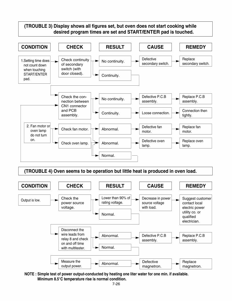
1.Setting time doesnot count downwhen touchingSTART/ENTERpad.
No continuity.
Continuity.
Defectivesecondary switch.
Replacesecondary switch.
Check continuityof secondaryswitch (withdoor closed).
Check the con-nection betweenCN1 connectorand PCBassembly.
2. Fan motor oroven lampdo not turnon.
Abnormal.Defective fanmotor.
Replace fanmotor.
Check fan motor.
Abnormal.Defective ovenlamp.
Replace ovenlamp.
Check oven lamp.
Normal.
No continuity.
Continuity.
Defective P.C.Bassembly.
Replace P.C.Bassembly.
Loose connection.Connection thentightly.
Output is low.Lower than 90% ofrating voltage.
Normal.
Decrease in powersource voltagewith load.
Suggest customercontact localelectric powerutility co. orqualifiedelectrician.
Check thepower sourcevoltage.
Disconnect thewire leads fromrelay 8 and checkon and off timewith multitester.
Abnormal.
Normal.
Abnormal. Defectivemagnetron.
Replacemagnetron.
Defective P.C.Bassembly.
Replace P.C.Bassembly.
Measure theoutput power.
(TROUBLE 3) Display shows all figures set, but oven does not start cooking whiledesired program times are set and START/ENTER pad is touched.
(TROUBLE 4) Oven seems to be operation but little heat is produced in oven load.
NOTE : Simple test of power output-conducted by heating one liter water for one min. if available.Minimum 8.5°C temperature rise is normal condition.

7-27
CONDITION CHECK RESULT CAUSE REMEDY
No microwaveoscillation.
No continuity.
Continuity.
Defective P.C.Bassembly
Replace P.C.Bassembly
Disconnect thewire leads fromrelay 8 andcheck continuityof relay 8.(Operate theunit)
Abnormal
normal
Defective highvoltagetransformer.
Replace highvoltagetransformer .
Check high vol-tage transformer
normal
normal
AbnormalDefective highvoltage Diode.
Replace highvoltage Diode.
Check high vol-tage diode.
AbnormalDefective highvoltage capacitor.
Replace highvoltage capacitor.
Check high vol-tage capacitor.
AbnormalDefectivemagnetron.
Replacemagnetron .
CheckMagnetron.
(TROUBLE 5) No microwave oscillation even though oven lamp and fan motor run(Display operates properly)
Output is full powerwhen you set lowerpower level.
Abnormal.Defective PCBassembly.
Replace PCBassembly.
Disconnect thewire leads fromrelay 8 and checkcontinuity relay 8.(Operate the unit)
NOTE: * Make sure the wire leads are in the correct position.* When removing the wire leads from parts be sure to grasp the connector not the wires.* When removing the magnetron, be sure to install the magnetron gasket in the correct position
and in good condition.
7-28
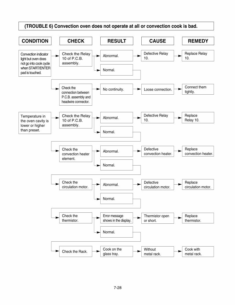
(TROUBLE 6) Convection oven does not operate at all or convection cook is bad.
CONDITION CHECK RESULT CAUSE REMEDY
Convection indicatorlight but oven doesnot go into cook cyclewhen START/ENTERpad is touched.
Abnormal.
Normal.
No continuity.Check theconnection betweenP.C.B. assembly andheadwire connector.
Defective Relay10.
Replace Relay10.
Loose connection.Connect themtightly.
Check the Relay10 of P.C.B.assembly.
Temperature inthe oven cavity islower or higherthan preset.
Abnormal.
Normal.
Abnormal.Check theconvection heaterelement.
Defective Relay10.
ReplaceRelay 10.
Defectiveconvection heater.
Replaceconvection heater.
Check the Relay10 of P.C.B.assembly.
Abnormal.Check thecirculation motor.
Defectivecirculation motor.
Replacecirculation motor.
Cook on theglass tray.
Check the Rack. Without metal rack.
Cook withmetal rack.
Error messageshows in the display.
Check thethermistor.
Thermistor openor short.
Replacethermistor.
Normal.
Normal.
Normal.

8-1
EXPLODED VIEW
DOOR PARTS
13581A
13551B
14760A
13213A
13552A
14026A
14970A
14890A
13650A
WTP004
WTT028
14760A
13581A
13551A
14760A
13213A
13552A
14026A
14970A
14890A
WTP004
WMP027
WTT028
14760A
WWS005
13650A
148902148901
#EV#
FOR MODEL: LMVH1750SBLMVH1750SW
FOR MODEL: LMVH1750ST

8-2
CONTROLLER PARTS
23506A
23572A
23551A
24781M
24810P
WTP015
268711
24781M
24810P
WTP015
268711
*07
*07
#EV#
FOR MODEL: LMVH1750SBLMVH1750SW
FOR MODEL: LMVH1750ST

8-3
OVEN CAVITY PARTSFor ModelLMVH1750SBLMVH1750ST
LMVH1750SWFor Model
For ModelLMVH1750SBLMVH1750SW
LMVH1750STFor Model
WTT027
WTT029
WTP013
WMP004
WTT022
WNH001
34960A33550P
33112U
33809A
63303A
34931A
36912H33740A
34890C
35230A
34810T
948501
330342
63302A
34810Q36549S
33530A
33531A
#EV#

8-4
LATCH BOARD PARTS
43500A
43501A
WSZ084
466001
466003
466001
44510A
#EV#

8-5
INTERIOR PARTS (I)
35026C
33390M
34370T
35889A
55893A
33052M
34980135300S
55013L
55900C
348103
53504A
948503948502
54810U
56208A
466002
54810D36549H
WWP008
WWP008WWS005
WWS005WNH003
348101
WTT028
WTT022
WTT022
WTT022
WTT021
WTT022
WTP013
WTP013
WTP013
WTP013
WTP005
WNH002
WSZ002
WSZ002
WSZ002
WTT028
WTT037
WTT028
WNH002
348102
56549B
56322A
55012A
53300S
36549C
568772
53300B56170D
54810A
56930M
56324A
54810C55900A
54974S56549F
55238A
56851D
50CZZH33390G
WTT028
WTT011
34930W
#EV#

8-6
INTERIOR PARTS (II)
56501A 352641
56930V
WTT028
WTT028
WTT028WTP005
WTP007
WTP007
WTT028
WTT028
352642
55231C
36549V
330341
53550L
36912H
50CZZM
55262A
56411A
55012U
568771
50FZZA
54931A
WTP005
WSZ002
WTT030
56201A
WTP018
#EV#

8-7
INSTALLATION PARTS
65862D
65862B
63300M
VINYLBAG
63861A
*01OWNERS MANUAL
*02SERVICEMANUAL
*06-1UPPERTEMPLATE
*06-2WALLTEMPLATE
*04INSTALLATIONMANUAL
*05COOKING GUIDE LABEL
#EV#
