microwave planning procedure 2
TRANSCRIPT
Aircom Connect 6.0 Link Planner
BASIC EXPLANATIONBASIC EXPLANATION
Aircom Connect 6.0 Link Planner
Aircom Connect Link Planner is a graphical planning tool that provides support for microwave network .
Planning is divided into two different categories : Point-to-Point Point-to-Multipoint
Link Planner is using two project database for the data:1 Properties (sites)2 Link (connection between different properties)
and some other database relates to the equipment

Aircom Connect 6.0 Link Planner
Database windows MapConnect Module
In order to use Link planner, you have to select the Connect module. After that you can start using the map or writing the database.
Aircom Connect 6.0 Link Planner
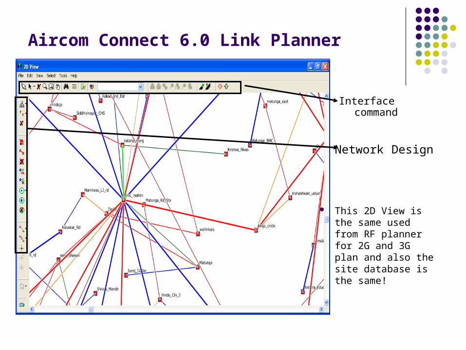
Network Design
This 2D View is the same used from RF planner for 2G and 3G plan and also the site database is the same!
Interface command

Aircom Connect 6.0 Link Planner
Selection
INTERFACE COMMANDINTERFACE COMMAND
Map Map visualizationvisualization
Map Map managingmanaging
Zoom
Drag
Search
Open Legend
Control Data types
Favorite selection
Create Vector
Vector Manager
Quick parameter display

Aircom Connect 6.0 Link Planner
Add Network Element (MSC / BSC / Site )Move Network Element
Delete Network Element
Candidates Manager RF Part
Remove Connection
Point to Multipoint Hub manager
NE CreationNE Creation
PropertProperty y ManageManagerr
LinkLink ManagManagerer
NETWORK DESIGNNETWORK DESIGN
Add Property
Move PropertyDelete Property
Add new link
Aircom Connect 6.0 Link Planner
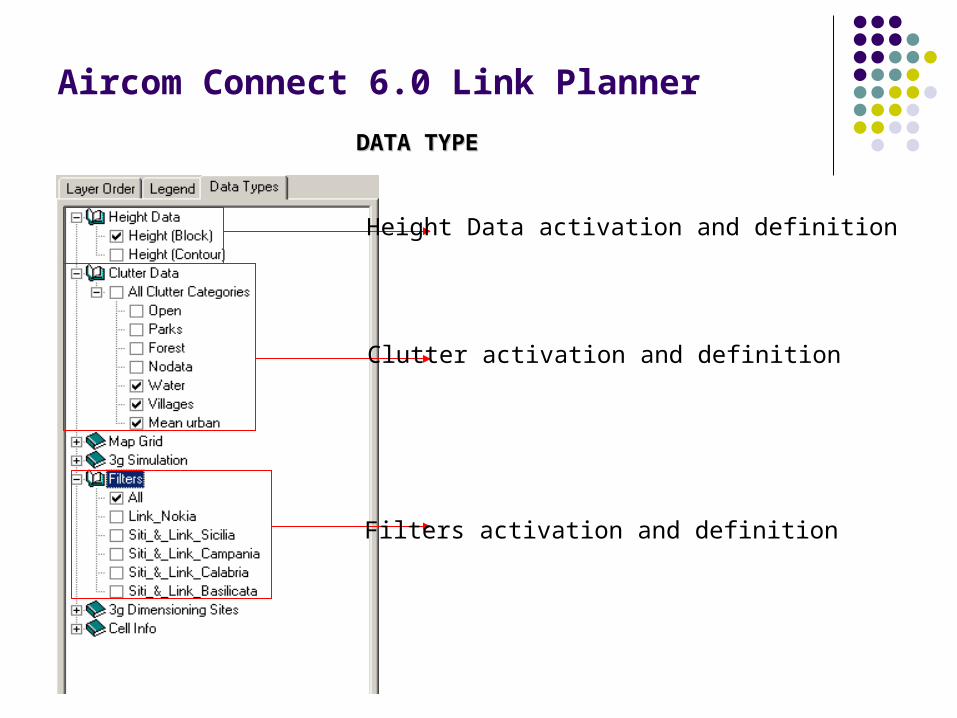
Height Data activation and definition
Clutter activation and definition
Filters activation and definition
DATA TYPE DATA TYPE
Aircom Connect 6.0 Link PlannerDATABASE SELECTIONDATABASE SELECTION
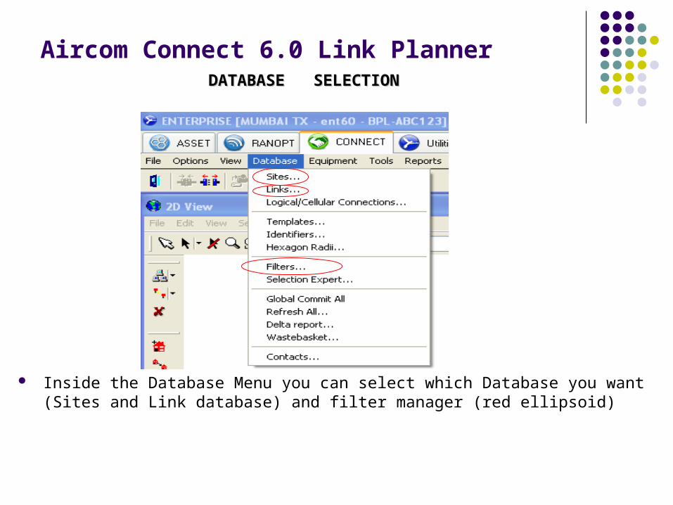
Inside the Database Menu you can select which Database you want (Sites and Link database) and filter manager (red ellipsoid)
Aircom Connect 6.0 Link PlannerEquipment SELECTIONEquipment SELECTION
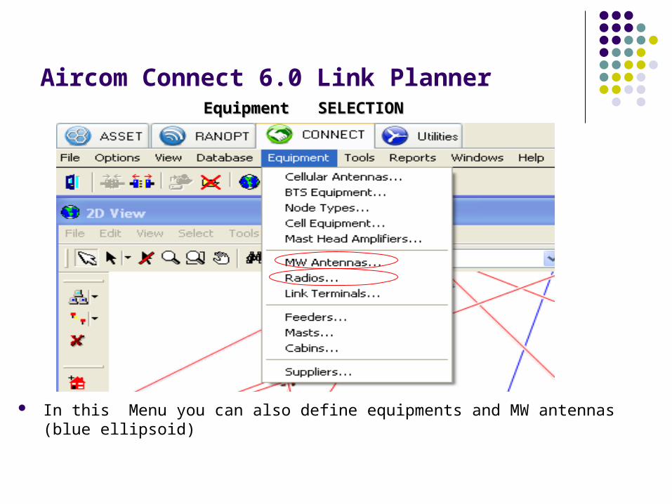
In this Menu you can also define equipments and MW antennas (blue ellipsoid)
Aircom Connect 6.0 Link PlannerSITE DATABASESITE DATABASE
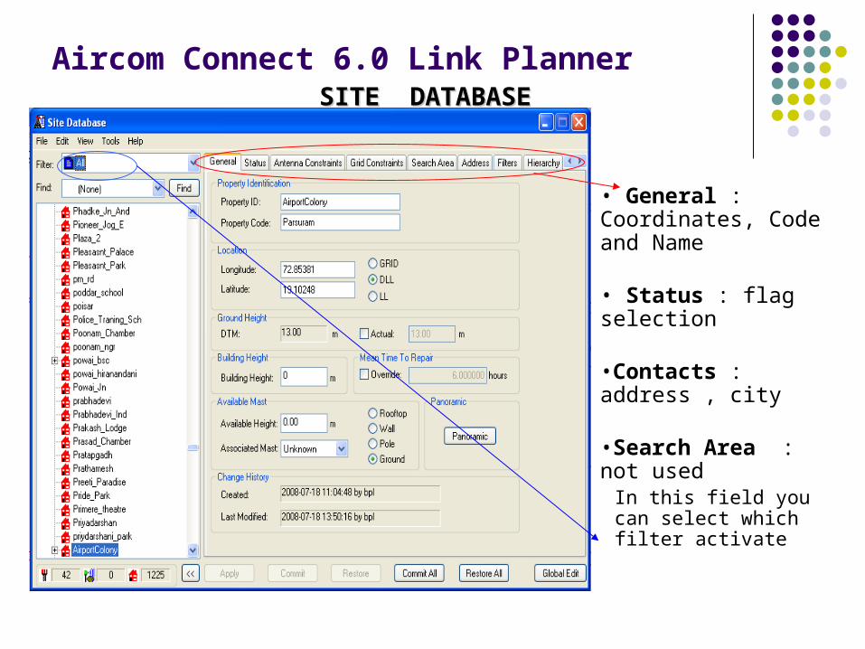
• General : Coordinates, Code and Name
• Status : flag selection
•Contacts : address , city
•Search Area : not used
In this field you can select which filter activate
Aircom Connect 6.0 Link Planner
LINK DATABASE LINK DATABASE
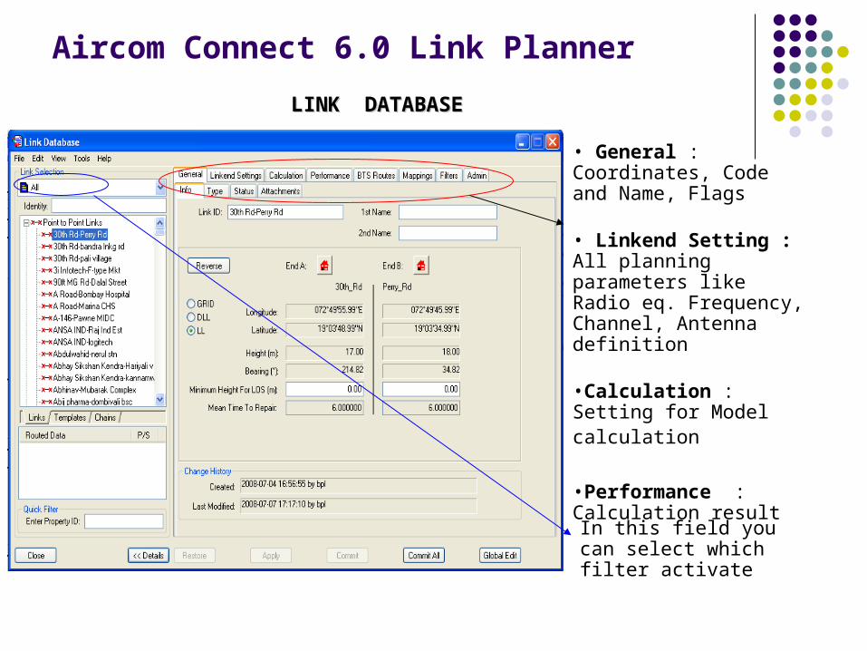
• General : Coordinates, Code and Name, Flags
• Linkend Setting : All planning parameters like Radio eq. Frequency, Channel, Antenna definition
•Calculation : Setting for Model calculation
•Performance : Calculation result
In this field you can select which filter activate
Aircom Connect 6.0 Link Planner
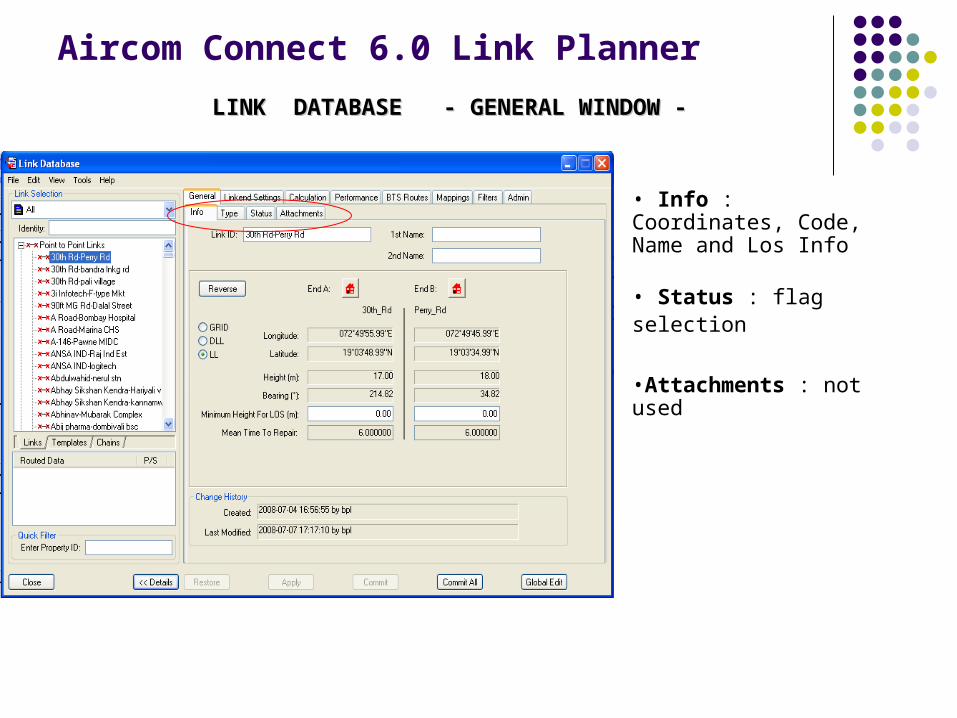
LINK DATABASE - GENERAL WINDOW -LINK DATABASE - GENERAL WINDOW -
• Info : Coordinates, Code, Name and Los Info
• Status : flag selection
•Attachments : not used
Aircom Connect 6.0 Link Planner
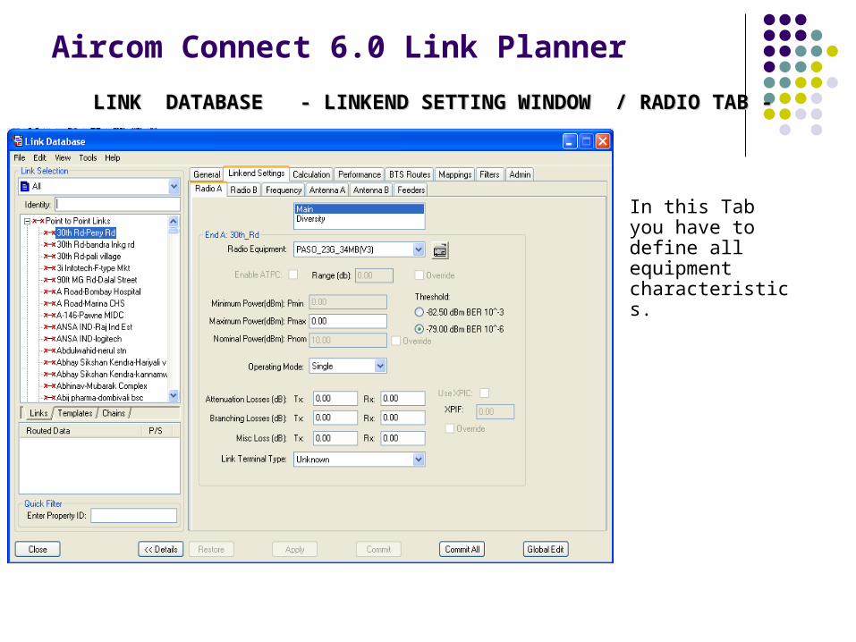
LINK DATABASE - LINKEND SETTING WINDOW / RADIO TAB -LINK DATABASE - LINKEND SETTING WINDOW / RADIO TAB -
In this Tab you have to define all equipment characteristics.
Aircom Connect 6.0 Link Planner
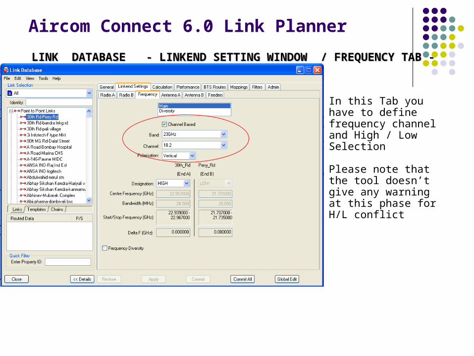
LINK DATABASE - LINKEND SETTING WINDOW / FREQUENCY TAB -LINK DATABASE - LINKEND SETTING WINDOW / FREQUENCY TAB -
In this Tab you have to define frequency channel and High / Low Selection
Please note that the tool doesn’t give any warning at this phase for H/L conflict

Aircom Connect 6.0 Link Planner
LINK DATABASE - LINKEND SETTING WINDOW / ANTENNA TAB -LINK DATABASE - LINKEND SETTING WINDOW / ANTENNA TAB -
You have to add an antenna, to select which one to use, fix the height and check the polarisation.
Please note that the tool doesn’t link between the antenna the polarisation!
Aircom Connect 6.0 Link Planner
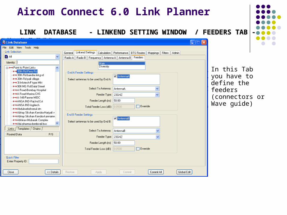
LINK DATABASE - LINKEND SETTING WINDOW / FEEDERS TAB -LINK DATABASE - LINKEND SETTING WINDOW / FEEDERS TAB -
In this Tab you have to define the feeders (connectors or Wave guide)

Aircom Connect 6.0 Link PlannerLINK DATABASE - CALCULATION WINDOW / PROPAG. PREDICTION TAB -LINK DATABASE - CALCULATION WINDOW / PROPAG. PREDICTION TAB -
In this Tab you have to define which Method you use and relative parameters

Aircom Connect 6.0 Link Planner
LINK DATABASE - CALCULATION WINDOW / RAINFALL TAB -LINK DATABASE - CALCULATION WINDOW / RAINFALL TAB -
In this Tab you have to define the rain rate. You can select a rain zone or put manually the value.
Aircom Connect 6.0 Link Planner
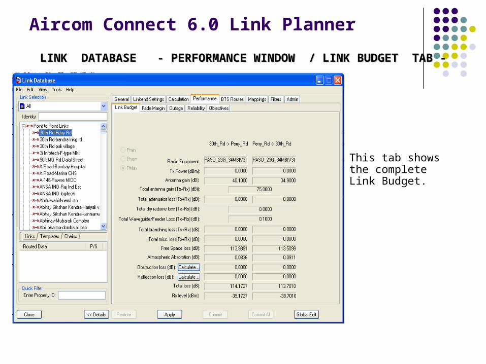
LINK DATABASE - PERFORMANCE WINDOW / LINK BUDGET TAB -LINK DATABASE - PERFORMANCE WINDOW / LINK BUDGET TAB -
This tab shows the complete Link Budget.
Aircom Connect 6.0 Link Planner
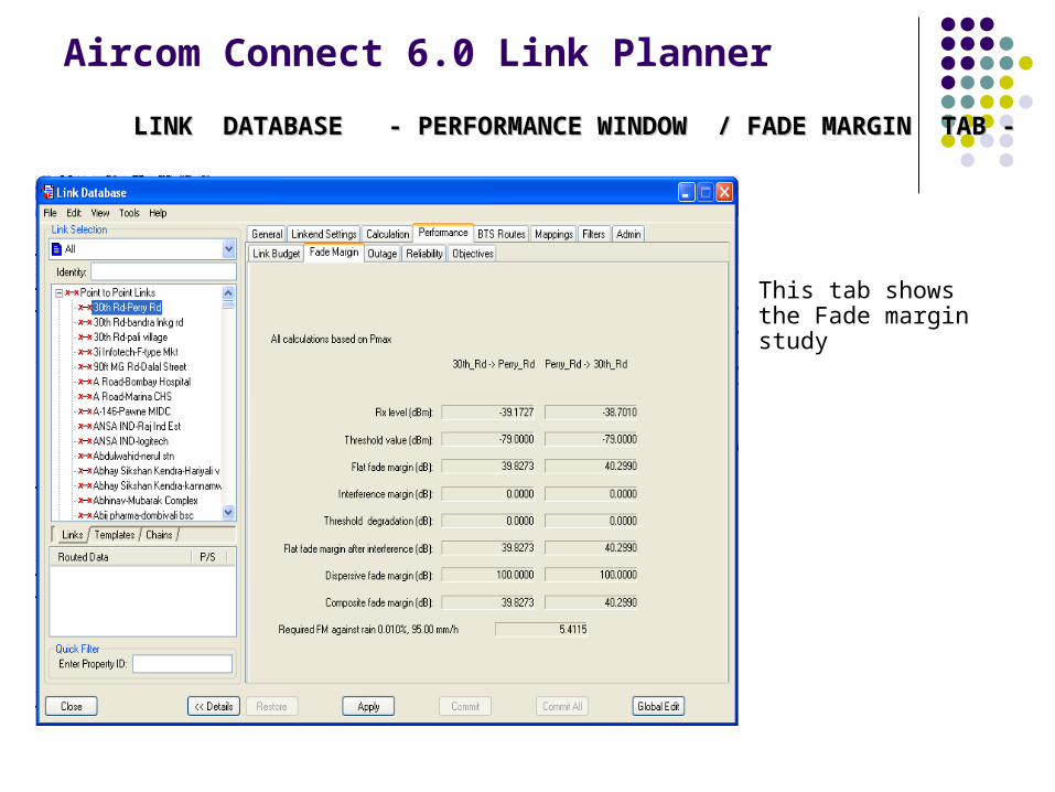
LINK DATABASE - PERFORMANCE WINDOW / FADE MARGIN TAB -LINK DATABASE - PERFORMANCE WINDOW / FADE MARGIN TAB -
This tab shows the Fade margin study

Aircom Connect 6.0 Link Planner
LINK DATABASE - PERFORMANCE WINDOW / AVAILABILITY TAB -LINK DATABASE - PERFORMANCE WINDOW / AVAILABILITY TAB -
This tab shows the Reliability and Availability of the link
Aircom Connect 6.0 Link PlannerINTERFERENCE TOOLINTERFERENCE TOOL
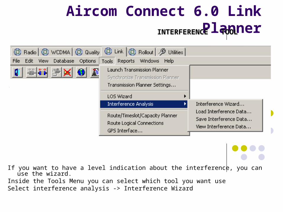
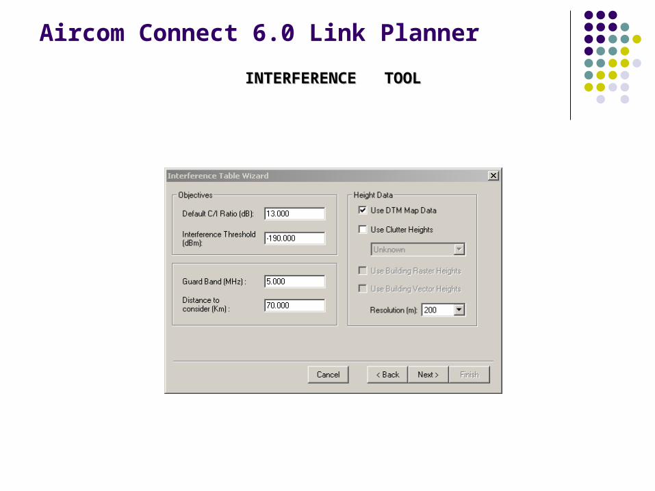
If you want to have a level indication about the interference, you can use the wizard.Inside the Tools Menu you can select which tool you want use Select interference analysis -> Interference Wizard
Aircom Connect 6.0 Link Planner
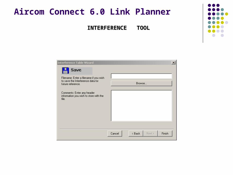
INTERFERENCE TOOLINTERFERENCE TOOL
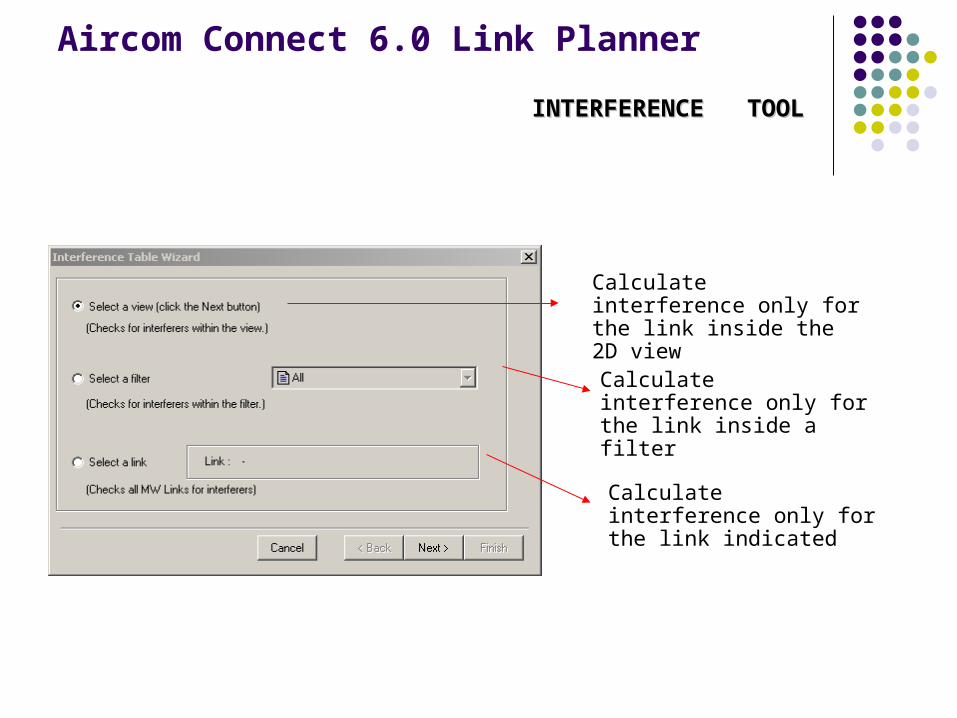
Calculate interference only for the link inside the 2D view
Calculate interference only for the link inside a filter
Calculate interference only for the link indicated
Aircom Connect 6.0 Link Planner
INTERFERENCE TOOLINTERFERENCE TOOL
Aircom Connect 6.0 Link Planner
INTERFERENCE TOOLINTERFERENCE TOOL
Aircom Connect 6.0 Link Planner
INTERFERENCE TOOLINTERFERENCE TOOL
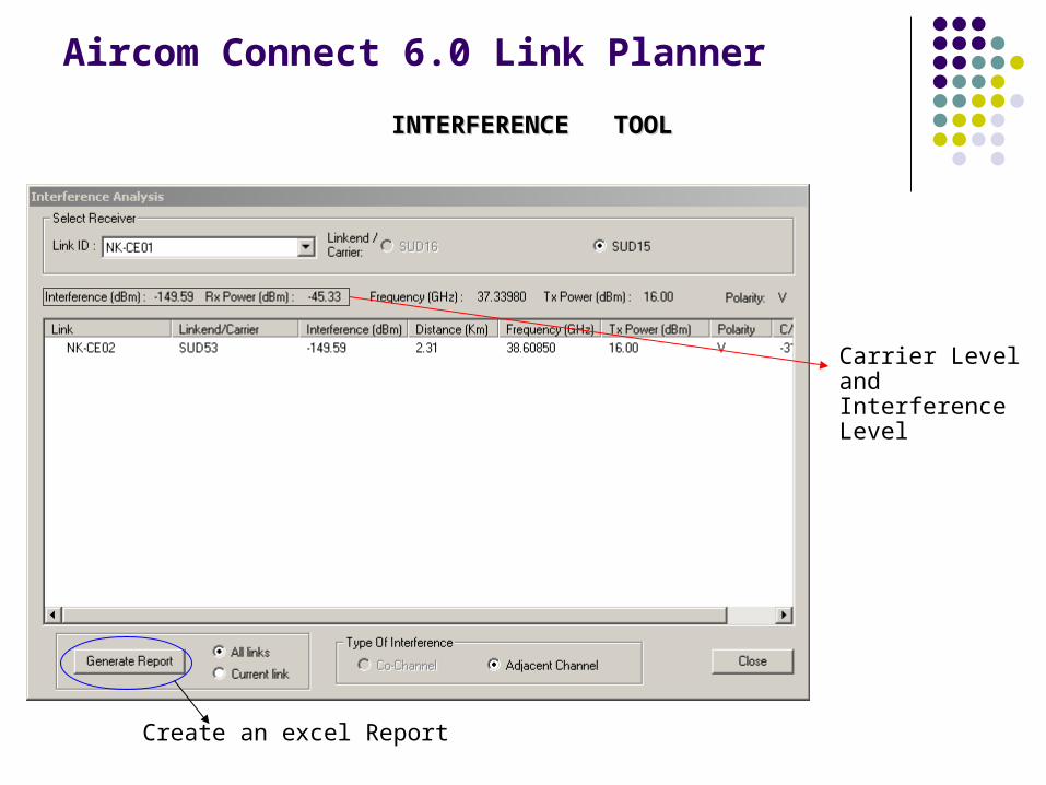
Carrier Level and Interference Level
Create an excel Report
Aircom Connect 6.0 Link Planner
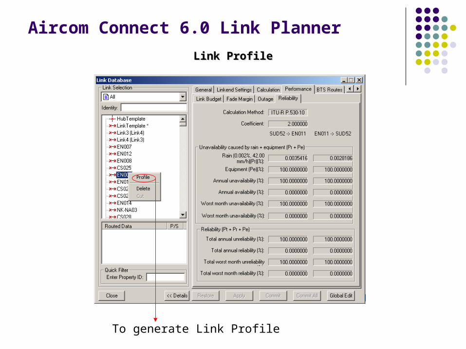
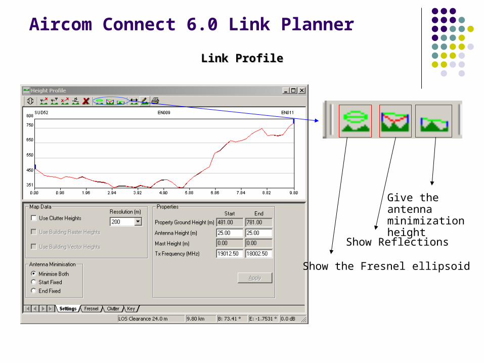
Link ProfileLink Profile
To generate Link Profile
Aircom Connect 6.0 Link Planner
Link ProfileLink Profile
Show the Fresnel ellipsoid
Show Reflections
Give the antenna minimization height
Aircom Connect 6.0 Link Planner
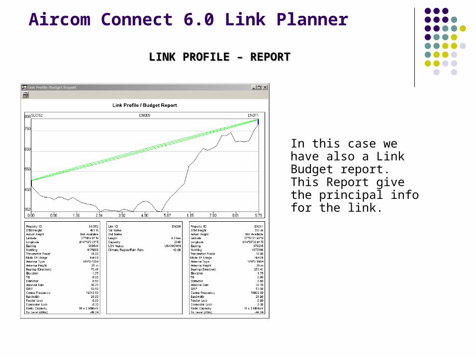
LINK PROFILE – REPORTLINK PROFILE – REPORT
In this case we have also a Link Budget report.This Report give the principal info for the link.
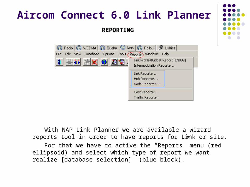
Aircom Connect 6.0 Link PlannerREPORTINGREPORTING
With NAP Link Planner we are available a wizard reports tool in order to have reports for Link or site.
For that we have to active the “Reports” menu (red ellipsoid) and select which type of report we want realize [database selection] (blue block).
Aircom Connect 6.0 Link Planner
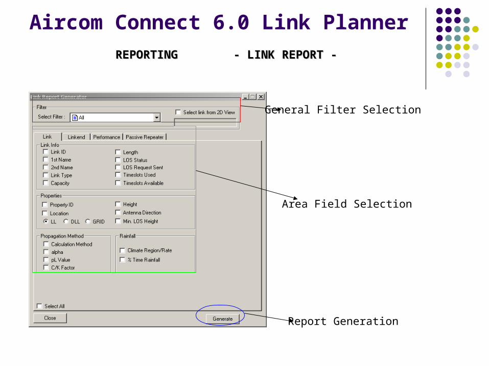
REPORTING - LINK REPORT -REPORTING - LINK REPORT -
General Filter Selection
Area Field Selection
Report Generation
Aircom Connect 6.0 Link Planner
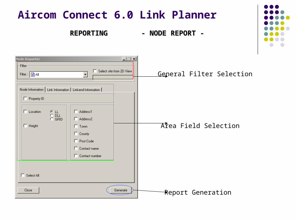
REPORTING - NODE REPORT -REPORTING - NODE REPORT -
General Filter Selection
Area Field Selection
Report Generation
Choice of Radio Equipment Fresenel Zone Clearance Objective Availability / Reliability Objectives Interference degradation Objectives Tower Height & Loading Restrictions
Link Designing: Basis of Design Criterion

Basis of Design Criterion
Link Design: The design of microwave links, involves three sets of calculations.
Working out antenna heights for the link. K-factor is major dominant variable. Earth bulge. Fresnel zone radius. Actual obstructions on the route Path Loss Operating frequency. Path profile: it indicates the distance from one of the transmitter site
where obstructions to the line of sight radio link may occur. The object of this calculation is to arrange tower heights along the
entire route of the link, so that an obstruction in the path does not enter into the fresnel zone by a specified amount for a specified K-factor used.
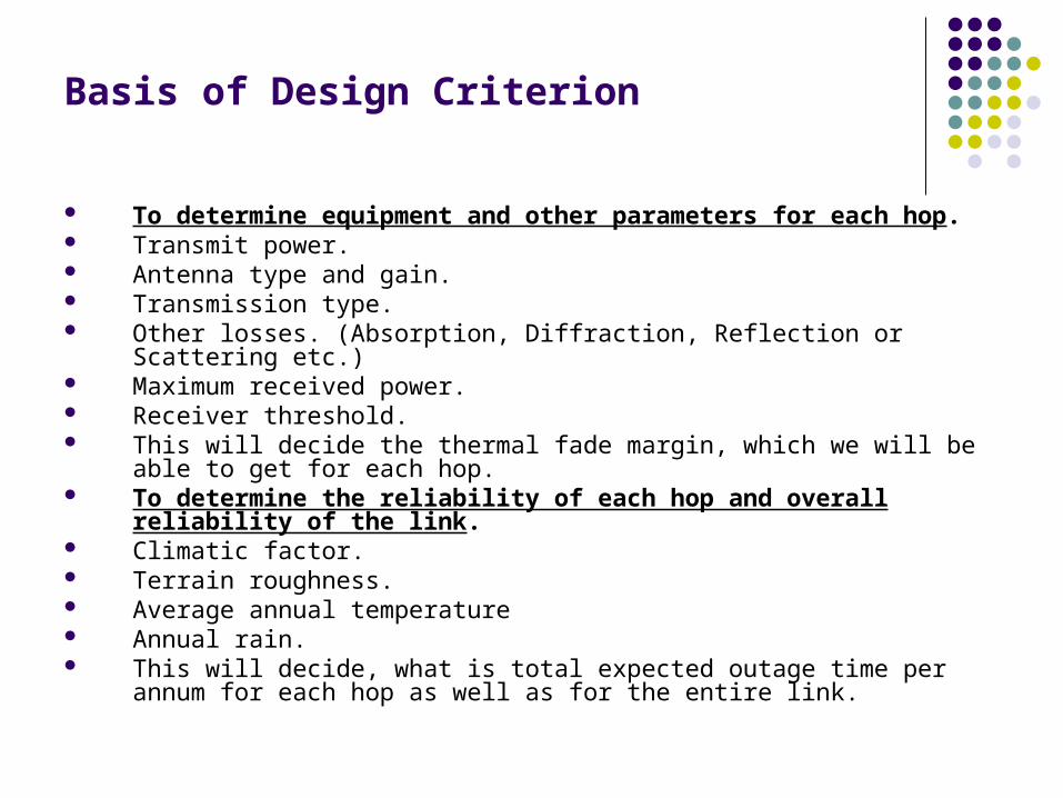
To determine equipment and other parameters for each hop. Transmit power. Antenna type and gain. Transmission type. Other losses. (Absorption, Diffraction, Reflection or Scattering etc.) Maximum received power. Receiver threshold. This will decide the thermal fade margin, which we will be able to get for each
hop. To determine the reliability of each hop and overall reliability of the link. Climatic factor. Terrain roughness. Average annual temperature Annual rain. This will decide, what is total expected outage time per annum for each hop
as well as for the entire link.
Basis of Design Criterion

Link Power Budget Receiver Sensitivity: The lowest Possible signal which can be detected by
receiver is called as Receiver Sensitivity or Threshold. This threshold value is manufacturer specific.
Fading: Received Signal vary with time due to multipath fading and rain etc. Refractive index of atmosphere varies with Temp. humidity and pressure which in turn cause the electromagnetic waves to change direction. Another cause for Multipath fading is ground reflection. So a fade margin is built in Link Designing.
Fade Margin: The fade margin is the power level, that, the unfaded received signal can fall to until it reaches the receiver threshold. This margin will vary depending on geographic and climatic conditions of different geographic areas and desired reliability of the system. Higher Fade Margin provides better link reliability. Typically it is 35-40 dB.
Fade Margin dB=Prx-Pthresh
Signal to Noise Ratio: It’s the minimum power difference between the wanted received signal and received noise.
Signal/Noise Ratio (dB)=10 log10 (Signal Power/Noise Power) Typically it is > 50 dB, logically it should be more than the Fade
Margin, so that it is always below the threshold level.
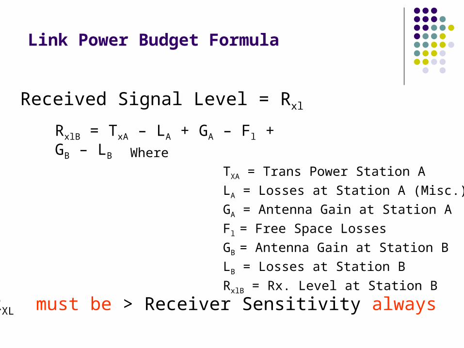
Link Power Budget Formula
Received Signal Level = Rxl
RxlB = TxA – LA + GA – Fl + GB – LB Where
TXA = Trans Power Station A
LA = Losses at Station A (Misc.)
GA = Antenna Gain at Station A
Fl = Free Space Losses
GB = Antenna Gain at Station B
LB = Losses at Station B
RxlB = Rx. Level at Station B
RXL must be > Receiver Sensitivity always
Important Formula
Free space losses)log(2045.92 fdL fs
d = distance in kilometers f = frequency in GHz
Basic Loss Formula
Propagation Loss
d = distance between Tx and Rx antenna [meter]
PT = transmit power [mW] PR = receive power [mW] G = antennae gain
2)4
(d
GPP TR

Fading
Phenomenon of Attenuation of Signal Due to Atmospheric and Propagation Conditions is called Fading
Fading can occur due to Refractions Reflections Atmospheric Anomalies
Fading
Types of Fading Multipath Fading Frequency Selective Fading Rain Fading
Multipath Fading
Multipath fading is caused due to reflected / refracted signals arriving at receiver Reflected Signals arrive with
Delay Phase Shift
Result in degradation of intended Signal
Space Diversity Radio Configuration is used to Counter Multipath Fading
Frequency Selective Fading
Frequency Selective Fading Due to Atmospheric anomalies different frequencies undergo different
attenuation levels Frequency Diversity Radio Configuration is used to Counter Frequency
Selective Fading
Rain Fading
Frequency Band > 10 GHz are affected due to Rain as Droplet size is comparable to Wavelengths
Rain Fading Occur over and above Multipath and Frequency Selective Fading
Horizontal Polarization is more prone to Rain Fades Path Diversity / Route Diversity is the only counter measure for Rain Fade
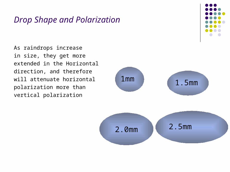
Drop Shape and Polarization
As raindrops increase
in size, they get more
extended in the Horizontal
direction, and therefore
will attenuate horizontal
polarization more than
vertical polarization
1mm 1.5mm
2.0mm 2.5mm
Link Engineering – Interference
Counter Measures Avoid Hi-Lo violation in loop Frequency Discrimination Polarization Discrimination Angular Discrimination High Performance Antennae Lower Transmit Power , if possible

PtP Microwave Transmission - Issues
Link Performance is Seriously Affected due to Atmospheric Anomalies like Ducting Ground Reflections Selective Fading Excessive Rains Interferences Thunderstorms / High Winds causing Antenna Misalignment Earthing Equipment Failure

Thank You !