microwave remote sensing intro psd
TRANSCRIPT
8/3/2019 Microwave Remote Sensing Intro Psd
http://slidepdf.com/reader/full/microwave-remote-sensing-intro-psd 1/78
11/18/02 University of Kansas
Microwave Remote Sensing: Principles andApplications
Outline² Introduction to RSL at the University of Kansas² Introduction and History of Microwave Remote Sensing² Active Microwave Sensors
Radar Altimeter. Scatterometer.
Imaging Radar.
² Applications of Active Sensors
Sea ice. Glacial ice Ocean winds. Soil Moisture. Snow. Vegetation. Precipitation. Solid Earth.

8/3/2019 Microwave Remote Sensing Intro Psd
http://slidepdf.com/reader/full/microwave-remote-sensing-intro-psd 2/78
11/18/02 University of Kansas
Microwave Remote Sensing: Principles andApplications
Passive Microwave Sensors² Radiometers
Traditional Interferometer
Polarimetric Radiometer Application of Passive Microwave Sensors
Sea ice. Glacial ice Soil Moisture.
Atmospheric sounding Snow. Vegetation. Precipitation

8/3/2019 Microwave Remote Sensing Intro Psd
http://slidepdf.com/reader/full/microwave-remote-sensing-intro-psd 3/78
11/18/02 University of Kansas
Radar Systems and Remote Sensing
Laboratory
WindvectorMeasurements overthe Ocean
Radar at 14 GHz.Concept developed at
KU.
USA, Europe and
Japan are planningto launch satellitesto obtain datacontinuously.

8/3/2019 Microwave Remote Sensing Intro Psd
http://slidepdf.com/reader/full/microwave-remote-sensing-intro-psd 4/78
11/18/02 University of Kansas
Radar Systems and Remote Sensing
Laboratory
Founded in 1964.
4 Faculty members, 20 Graduate students - Ph. D & M.S.4-6 Undergraduate students, 2 Staff
Now satellites based on concepts developed at RSL are in
operation. NSCAT, QUICKSCAT- Radars to measure ocean surface winds.
ADEOS-2 (JAPAN), Europeans Met Office is planning to launchsatellite to support operational applications.ScanSAR-
Radarsat- Canadian satellite
Envisat - EuropeanSRTM -Shuttle Radar Topography Mission.Radar Systems
and Remote Sensing Laboratory
8/3/2019 Microwave Remote Sensing Intro Psd
http://slidepdf.com/reader/full/microwave-remote-sensing-intro-psd 5/78
11/18/02 University of Kansas
Radar Systems and Remote Sensing
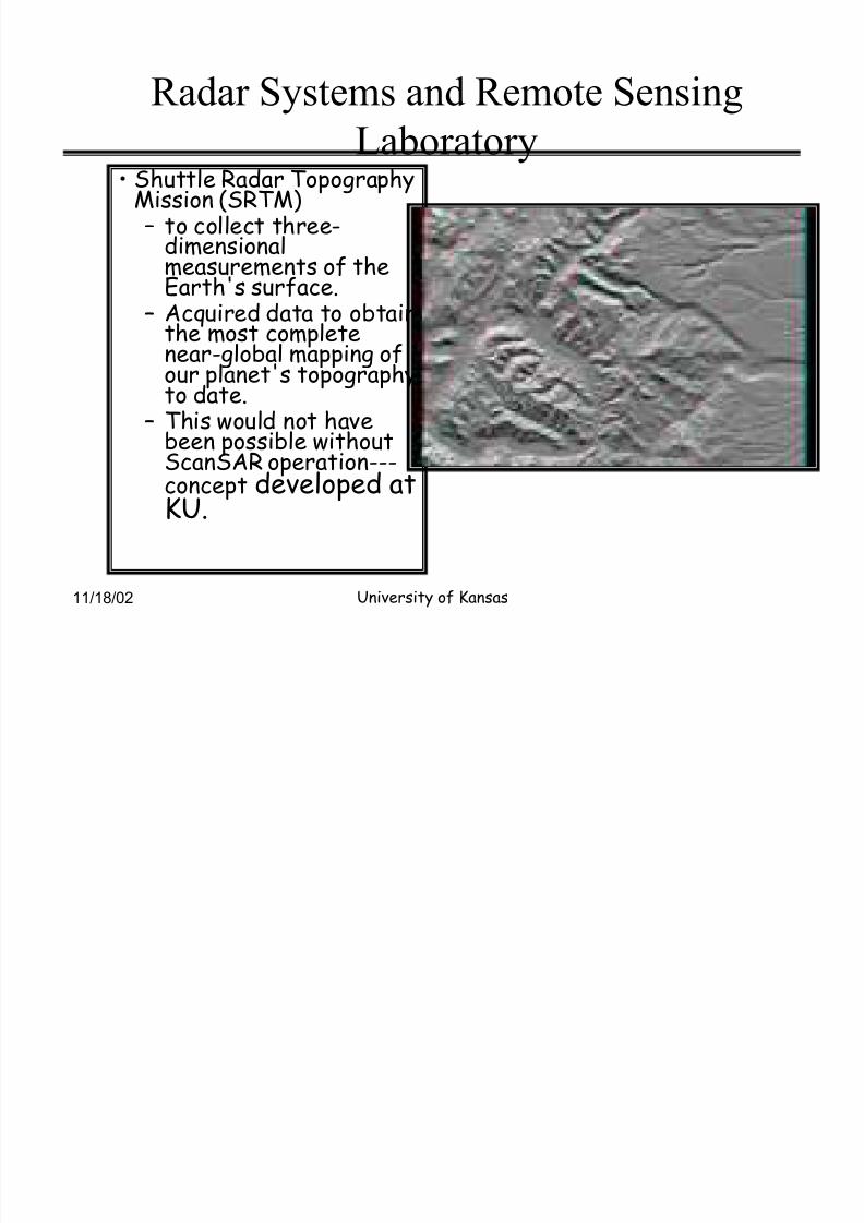
Laboratory Shuttle Radar TopographyMission (SRTM)² to collect three-
dimensionalmeasurements of theEarth's surface.
² Acquired data to obtainthe most completenear-global mapping ofour planet's topographyto date.
² This would not have
been possible withoutScanSAR operation---concept developed atKU.
8/3/2019 Microwave Remote Sensing Intro Psd
http://slidepdf.com/reader/full/microwave-remote-sensing-intro-psd 6/78
11/18/02 University of Kansas
ITTC² Information Technology &Telecommunication Center
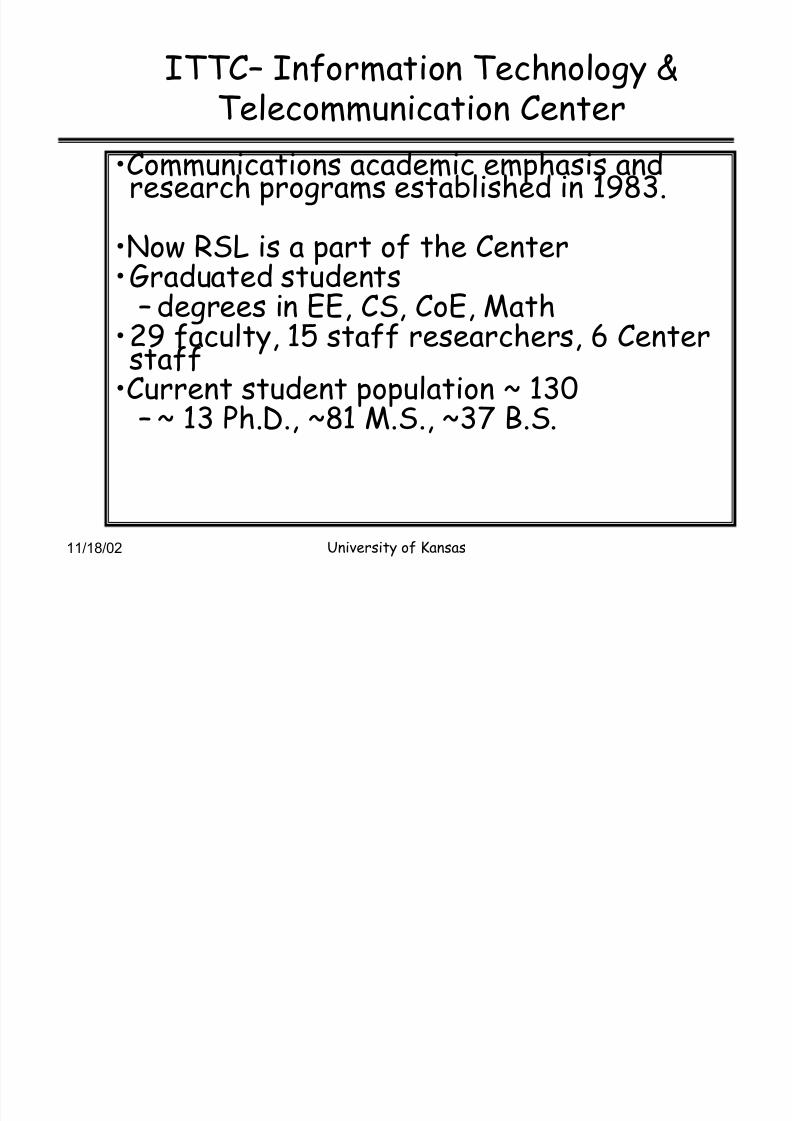
Communications academic emphasis andresearch programs established in 1983.
Now RSL is a part of the Center
Graduated students² degrees in EE, CS, CoE, Math29 faculty, 15 staff researchers, 6 Centerstaff
Current student population ~ 130² ~ 13 Ph.D., ~81 M.S., ~37 B.S.
8/3/2019 Microwave Remote Sensing Intro Psd
http://slidepdf.com/reader/full/microwave-remote-sensing-intro-psd 7/78
11/18/02 University of Kansas
EM Spectrum
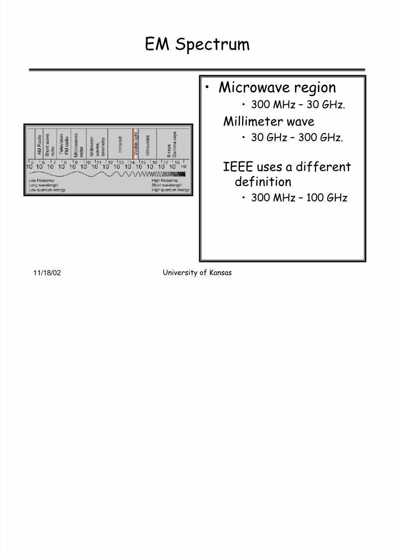
Microwave region 300 MHz ² 30 GHz.
Millimeter wave
30 GHz ² 300 GHz.
IEEE uses a differentdefinition
300 MHz ² 100 GHz
8/3/2019 Microwave Remote Sensing Intro Psd
http://slidepdf.com/reader/full/microwave-remote-sensing-intro-psd 8/78
11/18/02 University of Kansas
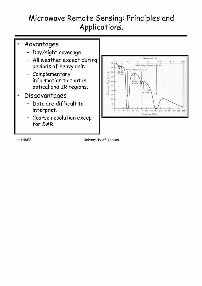
Microwave Remote Sensing: Principles andApplications.
Advantages² Day/night coverage.
² All weather except duringperiods of heavy rain.
² Complementaryinformation to that inoptical and IR regions.
Disadvantages
² Data are difficult tointerpret.
² Coarse resolution exceptfor SAR.

8/3/2019 Microwave Remote Sensing Intro Psd
http://slidepdf.com/reader/full/microwave-remote-sensing-intro-psd 9/78
11/18/02 University of Kansas
Microwave Remote Sensing³ history
US has a long history in Microwave Remote Sensing.
² Clutter Measurement program after theWW-II.
Ohio State University collected a large data
base of clutter on variety of targets.
² Earnest studies for the remote sensing of theearth can be considered to have began 1960s.
In 1960s NASA initiated studies to investigatethe use of microwave technology to earthobservation.
8/3/2019 Microwave Remote Sensing Intro Psd
http://slidepdf.com/reader/full/microwave-remote-sensing-intro-psd 10/78
11/18/02 University of Kansas
Microwave Remote Sensing³ history
The research NASA and other agencies initiated resulted in:
² Development of ground-based and airborne sensors.² Measurement of emission and scattering characteristics of
many natural targets.² Development of models to explain and understand measured
data.² Space missions with microwave sensors.
NIMBUS
² Radiometers. SKYLAB² Radar and Radiometers

8/3/2019 Microwave Remote Sensing Intro Psd
http://slidepdf.com/reader/full/microwave-remote-sensing-intro-psd 11/78
11/18/02 University of Kansas
Microwave Remote Sensing
Radar² Radio Detection and
Ranging.
² Texts: Skolnik, M. I.,Introduction to RadarSystems, McGraw Hill,1981.
Stimson, G.W.,Introduction to AirborneRadar, SciTechPublishing, 1998.
Applications
Civilian
Navigation and
tracking
Search and
surveillance
Imaging &
Mapping
Weather
Sounding
Probing
Remote sensing
MilitaryNavigation and
tracking
Search and
surveillance
Imaging &
Mapping
Weather
Proximity fuses
Counter measures
8/3/2019 Microwave Remote Sensing Intro Psd
http://slidepdf.com/reader/full/microwave-remote-sensing-intro-psd 12/78
11/18/02 University of Kansas
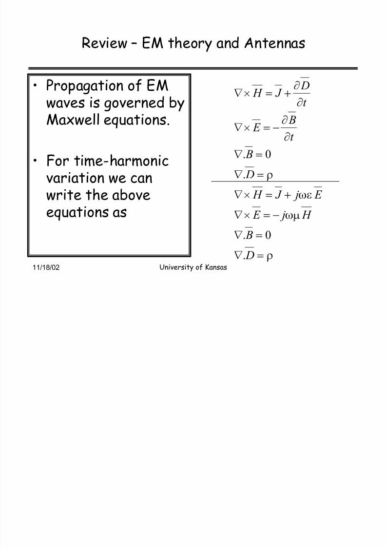
Review ² EM theory and Antennas
Propagation of EMwaves is governed byMaxwell equations.
For time-harmonicvariation we can
write the aboveequations as
V
[Q
[I
V
!
!
!v
!v
!
!x
x!v
x
x!v
D
B
H j E
E j J H
D
B
t
B E
t
D J H
.
0.
.
0.

8/3/2019 Microwave Remote Sensing Intro Psd
http://slidepdf.com/reader/full/microwave-remote-sensing-intro-psd 13/78
11/18/02 University of Kansas
EM Theory
Helmholtz Equation² From the four
Maxwell equations,
we can derive vectorHelmholtz equations
² For each component
of E and H field wecan write a scalarequation
0
0
0
0
0
2
2
2
2
2
2
2
2
2
2
2
2
2
2
2
2
2
2
2
2
2
2
2
2
2
!x
x
x
x
x
x
!x
x
x
x
x
x
!x
x
x
x
x
x
!
!
!
z z z z
y
y y y
x x x x
E z
E
y
E
x
E
E z
E
y
E
x
E
E z
E
y
E
x
E
where
H H
E E
K
K
K
QI[K
K
K
8/3/2019 Microwave Remote Sensing Intro Psd
http://slidepdf.com/reader/full/microwave-remote-sensing-intro-psd 14/78
11/18/02 University of Kansas
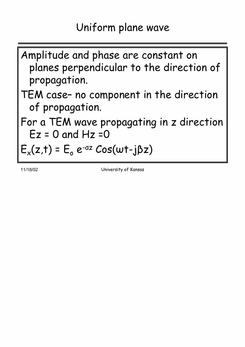
Uniform plane wave
Amplitude and phase are constant onplanes perpendicular to the direction of
propagation.TEM case² no component in the directionof propagation.
For a TEM wave propagating in z directionEz = 0 and Hz =0
Ex(z,t) = Eo e-z Cos(t-jz)
8/3/2019 Microwave Remote Sensing Intro Psd
http://slidepdf.com/reader/full/microwave-remote-sensing-intro-psd 15/78
11/18/02 University of Kansas
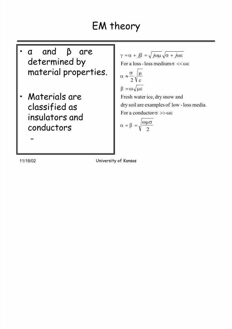
EM theory
and aredetermined bymaterial properties.
Materials areclassified as
insulators andconductors²
2
conductor aFor
media.loss-lowof examplesaresoildry
andsnowdryice,r Fresh wate
2
mediumloss-lossaFor
[QW FE
[IW
QI[ FI
QWE
[IW
[IW[Q FEK
!!
""
!
}
!! j j j

8/3/2019 Microwave Remote Sensing Intro Psd
http://slidepdf.com/reader/full/microwave-remote-sensing-intro-psd 16/78
11/18/02 University of Kansas
EM Theory
Reflection andrefraction² Whenever a wave
impinges on adielectric interface,part of the wave willbe reflected andremaining will betransmitted into thelower medium.
i r
t

8/3/2019 Microwave Remote Sensing Intro Psd
http://slidepdf.com/reader/full/microwave-remote-sensing-intro-psd 17/78
11/18/02 University of Kansas
EM Theory--Scattering
Microwave Scattering from adistributed target depends on
² Dielectric constant.² Surface roughness.
² Internal structure. Homogeneous
Inhomogeneous² Wavelength or Frequency.
² Polarization.

8/3/2019 Microwave Remote Sensing Intro Psd
http://slidepdf.com/reader/full/microwave-remote-sensing-intro-psd 18/78
11/18/02 University of Kansas
Microwave Scattering
Surface scattering² A surface is classified as
smooth or rough bycomparing its surfaceheight deviation withwavelength.
Smooth h < /32cos()
For example at 1.5
GHz and = 60 deg., h < 1.25 cm
i r
Smooth surface
Moderately roughsurface
Very rough surface

8/3/2019 Microwave Remote Sensing Intro Psd
http://slidepdf.com/reader/full/microwave-remote-sensing-intro-psd 19/78
11/18/02 University of Kansas
Microwave Scattering
Rough surface scattering

8/3/2019 Microwave Remote Sensing Intro Psd
http://slidepdf.com/reader/full/microwave-remote-sensing-intro-psd 20/78
11/18/02 University of Kansas
Microwave Scattering
Volume scattering² Material is
inhomogeneous such
as Snow
Firn
Vegetation
Multiyear ice
)()(20
t
o
v s
o
T T UW UWW !
8/3/2019 Microwave Remote Sensing Intro Psd
http://slidepdf.com/reader/full/microwave-remote-sensing-intro-psd 21/78
11/18/02 University of Kansas
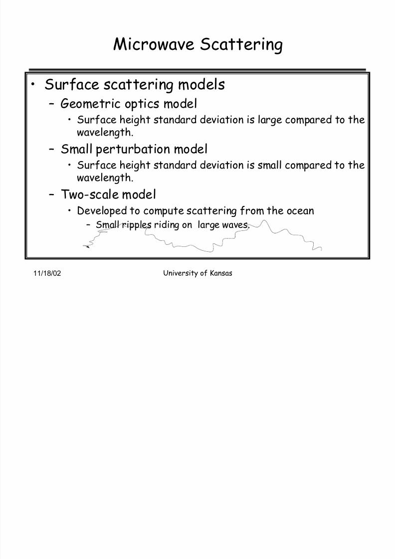
Microwave Scattering
Surface scattering models² Geometric optics model
Surface height standard deviation is large compared to thewavelength.
² Small perturbation model Surface height standard deviation is small compared to the
wavelength.
² Two-scale model
Developed to compute scattering from the ocean² Small ripples riding on large waves.

8/3/2019 Microwave Remote Sensing Intro Psd
http://slidepdf.com/reader/full/microwave-remote-sensing-intro-psd 22/78
11/18/02 University of Kansas
Antennas
Antennas are used to couple electromagneticwaves into free space or captureelectromagnetic waves from free space.
Type of antennas² Wire
Dipole
Loop antenna
² Aperture Parabolic dish
Horn
8/3/2019 Microwave Remote Sensing Intro Psd
http://slidepdf.com/reader/full/microwave-remote-sensing-intro-psd 23/78
11/18/02 University of Kansas
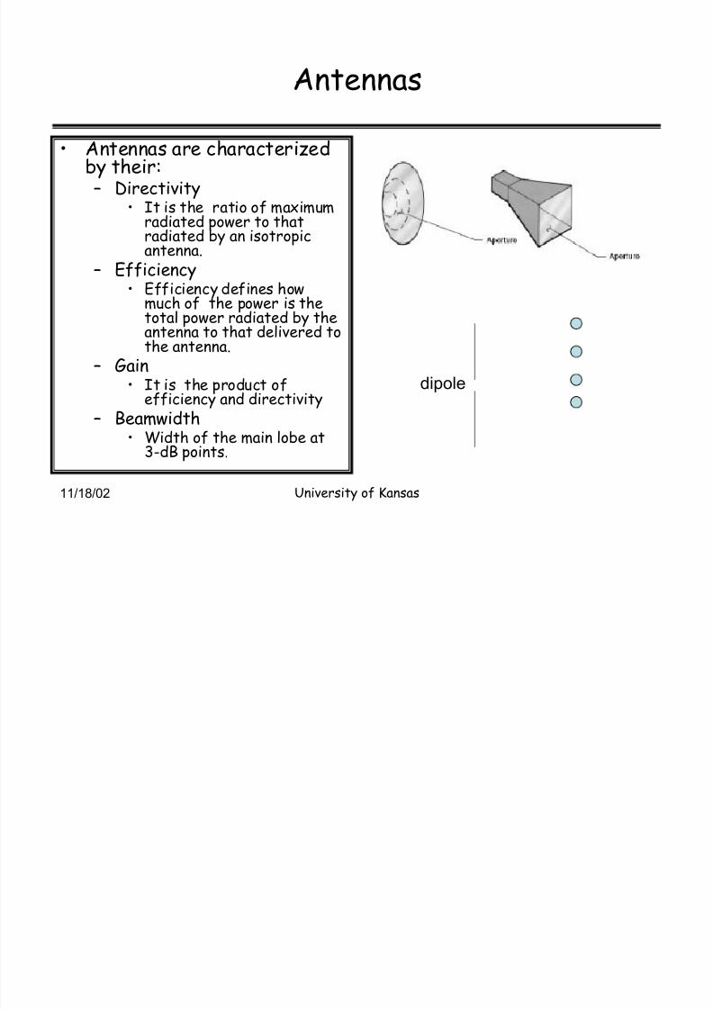
Antennas
Antennas are characterizedby their:² Directivity
It is the ratio of maximumradiated power to thatradiated by an isotropic
antenna.² Efficiency
Efficiency defines howmuch of the power is thetotal power radiated by theantenna to that delivered tothe antenna.
² Gain It is the product ofefficiency and directivity
² Beamwidth Width of the main lobe at
3-dB points.
dipole

8/3/2019 Microwave Remote Sensing Intro Psd
http://slidepdf.com/reader/full/microwave-remote-sensing-intro-psd 24/78
11/18/02 University of Kansas
Antenna gain
8/3/2019 Microwave Remote Sensing Intro Psd
http://slidepdf.com/reader/full/microwave-remote-sensing-intro-psd 25/78
11/18/02University of Kansas
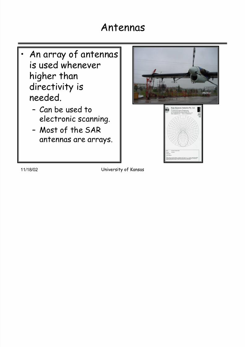
Antennas
An array of antennasis used wheneverhigher than
directivity isneeded.² Can be used to
electronic scanning.
² Most of the SARantennas are arrays.

8/3/2019 Microwave Remote Sensing Intro Psd
http://slidepdf.com/reader/full/microwave-remote-sensing-intro-psd 26/78
11/18/02University of Kansas
Antenna Array
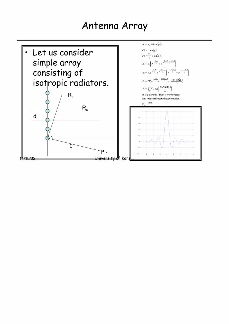
Let us considersimple arrayconsisting of
isotropic radiators.
sinx
E
.expressionresultingthereduceand
degrees90to0from increaseweIf
sin2cos
)sincos2
sin2
sin
sin
t
)sin2
sinsinsin2
sin(22
1
0
0
0
x
d E E
d ee E E
eeee E E
ee E E
d
d R
d R R
i
oit
d j
R j
ot
d j
d j
d j
R j
ot
d R j
R j
ot
o
o
w
¹ º
¸©ª
¨w
!
¹¹ º
¸©©ª
¨!
¹¹ º
¸©©ª
¨!
!x
!x
!
§
P
UT
P UT
UP
TN
U
U
P
UT
P
T
P
UT
P
UT
P
UT
P
T
P
UT
P
T
P
Ro
d
R1
U
8/3/2019 Microwave Remote Sensing Intro Psd
http://slidepdf.com/reader/full/microwave-remote-sensing-intro-psd 27/78
11/18/02University of Kansas
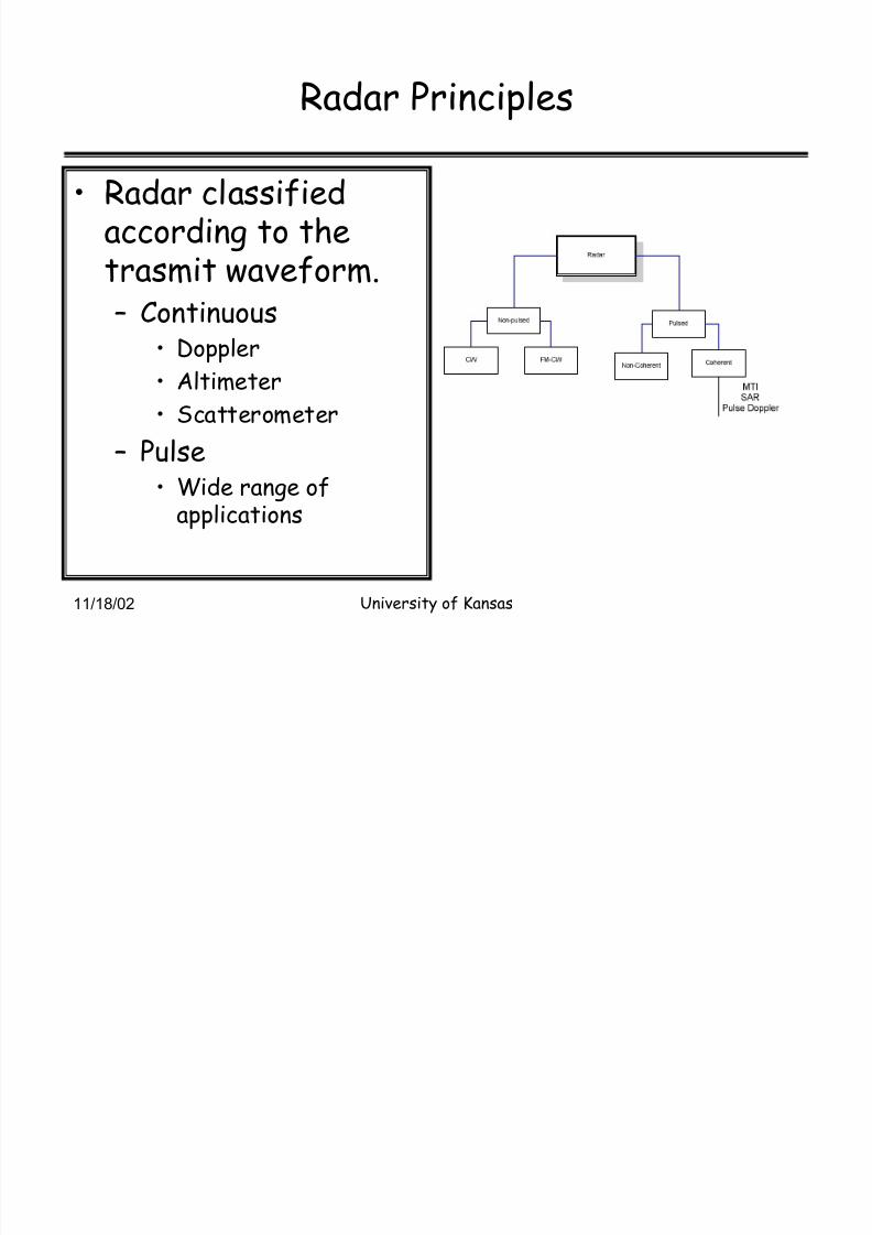
Radar Principles
Radar classifiedaccording to thetrasmit waveform.
² Continuous Doppler
Altimeter
Scatterometer
² Pulse Wide range ofapplications

8/3/2019 Microwave Remote Sensing Intro Psd
http://slidepdf.com/reader/full/microwave-remote-sensing-intro-psd 28/78
11/18/02 University of Kansas
Radar Principles
Radar measuresdistance bymeasuring time delay
between thetransmit andreceived pulse.² 1 us = 150 m
² 1 ns = 15 cm
Radar
jet.thetoRangeR
n propagatioof velocityc
receptionand
ansmission between tr delaytime
2
!
!
!
!
X
Xc R

8/3/2019 Microwave Remote Sensing Intro Psd
http://slidepdf.com/reader/full/microwave-remote-sensing-intro-psd 29/78
11/18/02 University of Kansas
Radar³ principle
Unambiguous rangeand Pulse RepetitionFrequency (PRF)
² PRF also determinesthe maximum dopplerwe can measure witha radar³ SAR.
² PRF > 2 fdmax
s1for 150 ,2
10015002
103R
Hz1500f radar withaFor
2
1,
p
8
un
p
QXX
!!(!(
!!
!
!
!
!
mr c
r
k m x
x
f
C R
T f PRF
T PRI
p
p
un
p

8/3/2019 Microwave Remote Sensing Intro Psd
http://slidepdf.com/reader/full/microwave-remote-sensing-intro-psd 30/78
11/18/02 University of Kansas
Radar³Principle
Radar equation For a monostatic radar
GT = GR
Radar sensitivity is determinedby the minimum detectablesignal set by the receiver noise.
No = kTBF
F= noise figure
Signal-to-noise ratio
2
43
2
T
22
Tr
22
T
ri
2
Tdr
2
Td
4
)4(
P
44
PP
bygivenisitandsignalincidentAe,aperture,effectiveanwithantennareceiveThe
4
1
4
P
P
bygivenisantennaon theincident power Reradiated
4
PP
radar.theof directionin the
reradiatesandsignalthisof parta
intercepts,section,crossradar hTarget wit
4
P P
byPgivenistargetat thedensityPower
P
T
T
WP
TW
T
TWT
WT
W
T
e R
RT r
eT
T
T
T
AGwhere
R
GG P
R
A
R
G
R R
G
R
G
R
G
!
!
!
!
!
!
PT
GT R
4
1
3
22
max
43
22
)4(
)4(
K TB F N
S
G P R
K TB F R
G P
N
P
N
S
T T
T T
o
r
T
WP
T
WP
!
!!
I1

8/3/2019 Microwave Remote Sensing Intro Psd
http://slidepdf.com/reader/full/microwave-remote-sensing-intro-psd 31/78
Slide 30
I1 ITTC, 11/11/2002

8/3/2019 Microwave Remote Sensing Intro Psd
http://slidepdf.com/reader/full/microwave-remote-sensing-intro-psd 32/78
11/18/02 University of Kansas
Microwave Remote Sensing
Radar cross sectioncharacterizes thesize of the object as
seen by the radar.Where
Es = scattering field
Ei = incident field
2
2
2
4
i
s
R Lim
E
E RTW gp!
r
2
r TW !
8/3/2019 Microwave Remote Sensing Intro Psd
http://slidepdf.com/reader/full/microwave-remote-sensing-intro-psd 33/78
11/18/02 University of Kansas
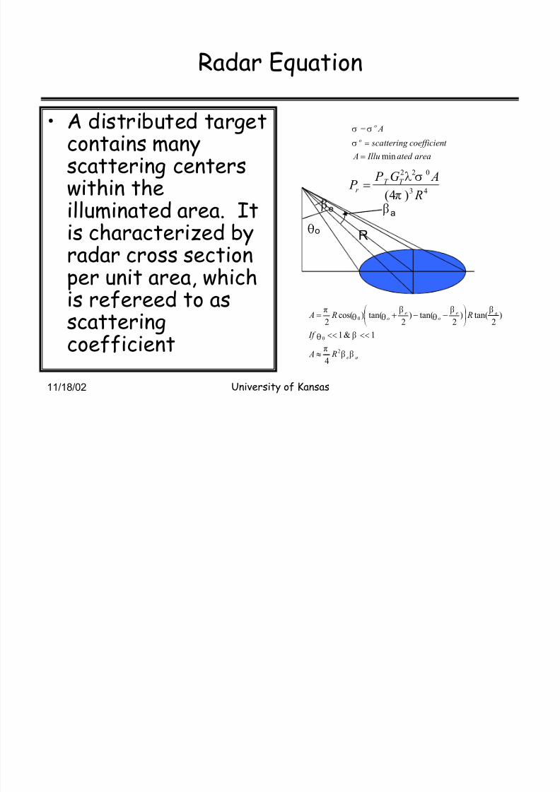
Radar Equation
A distributed targetcontains manyscattering centers
within theilluminated area. Itis characterized byradar cross sectionper unit area, which
is refereed to asscatteringcoefficient
areaated Illu A
t coe fficien scatter ing
A
o
o
min
!
!
!
W
WW
43
022
)4( R
AG P P T T
r
T
WP!
Fe
R Uo
ae
aeo
eo
R A
If
R R A
F FT
F U
F F U
F U U
T
2
0
0
4
1&1
)2
tan()2
tan()2
tan()cos(2
}
¹ º
¸©ª
¨!
Fa
8/3/2019 Microwave Remote Sensing Intro Psd
http://slidepdf.com/reader/full/microwave-remote-sensing-intro-psd 34/78
11/18/02 University of Kansas
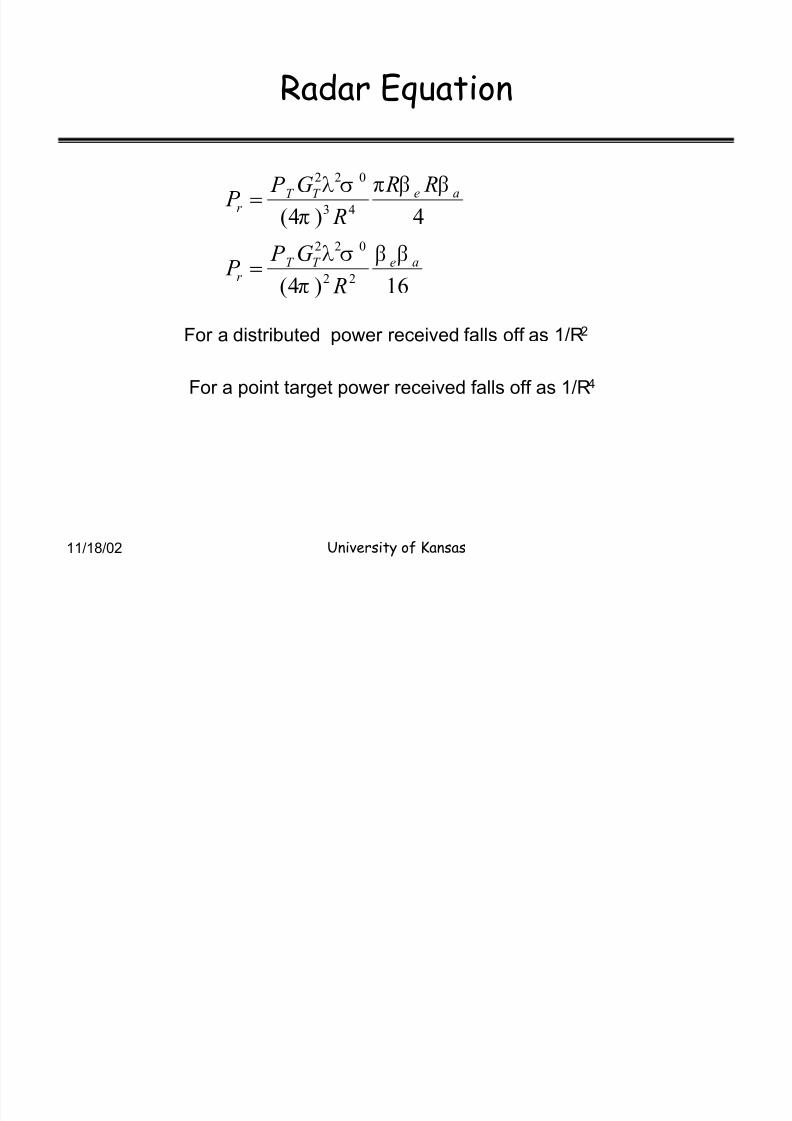
Radar Equation
16)4(
4)4(
22
022
43
022
aeT T
r
aeT T r
R
G P P
R R
R
G P P
F F
T
WP
F FT
T
WP
!
!
For a distributed power received falls off as 1/R2
For a point target power received falls off as 1/R4
8/3/2019 Microwave Remote Sensing Intro Psd
http://slidepdf.com/reader/full/microwave-remote-sensing-intro-psd 35/78
11/18/02 University of Kansas
Antenna Array
Let us considersimple arrayconsisting of
isotropic radiators.
sinx
E
.expressionresultingthereduceand
degrees90to0from increaseweIf
sin2cos
)sin
cos2
sin2
sin
sin
t
)sin2
sinsinsin2
sin(22
1
0
0
0
x
d E E
d ee E E
eeee E E
ee E E
d
d R
d R R
i
oit
d j
R j
ot
d j
d j
d j
R j
ot
d R j
R j
ot
o
o
w
¹ º
¸©ª
¨w
!
¹¹ º
¸©©ª
¨!
¹¹ º
¸©©ª
¨!
!x
!x
!
§
P
UT
P
UT
UP
TN
U
U
P
UT
P
T
P
UT
P
UT
P
UT
P
T
P
UT
P
T
P
Ro
d
R1
U

8/3/2019 Microwave Remote Sensing Intro Psd
http://slidepdf.com/reader/full/microwave-remote-sensing-intro-psd 36/78
11/18/02 University of Kansas
Antenna Array
Let us considersimple arrayconsisting of
isotropic radiators.
sinx
E
.expressionresultingthereduceand
degrees90to0from increaseweIf
sin2cos
)sin
cos2
sin2
sin
sin
t
)sin2
sinsinsin2
sin(22
1
0
0
0
x
d E E
d ee E E
eeee E E
ee E E
d
d R
d R R
i
oit
d j
R j
ot
d j
d j
d j
R j
ot
d R j
R j
ot
o
o
w
¹ º
¸©ª
¨w
!
¹¹ º
¸©©ª
¨!
¹¹ º
¸©©ª
¨!
!x
!x
!
§
P
UT
P
UT
UP
TN
U
U
P
UT
P
T
P
UT
P
UT
P
UT
P
T
P
UT
P
T
P
Ro
d
R1
U

8/3/2019 Microwave Remote Sensing Intro Psd
http://slidepdf.com/reader/full/microwave-remote-sensing-intro-psd 37/78
11/18/02 University of Kansas
Microwave Remote Sensing: Principles andApplications³ History
Active Microwave sensing² Studies related to active sensing of the
earth beagn in 1960s. Clutter studies
SkYLab ² radar altimeter and scatterometer in1960s
SEASAT in 1978
ERS-1, JERS-1, ERS-2, RADARSAT, GEOSAT,Topex-Posoidon

8/3/2019 Microwave Remote Sensing Intro Psd
http://slidepdf.com/reader/full/microwave-remote-sensing-intro-psd 38/78
11/18/02 University of Kansas
Active Sensors ² Radar Altimeter
Radar altimeter is a short pulse radarused for accurate height measurements.² Ocean topography.
² Glacial ice topography
² Sea ice characteristics Classification and ice edge
Vegetationhttp://topex-www. j pl.nasa.gov/technology/images/P38232. j pg

8/3/2019 Microwave Remote Sensing Intro Psd
http://slidepdf.com/reader/full/microwave-remote-sensing-intro-psd 39/78
11/18/02 University of Kansas
Radar Altimeter
MissionsSatellite Radar Altimeters
Mission Frequency Accuracy Period
SKYLAB Ku 10 m 1973
GEOS Ku 1-5 M 1976
SEASAT Ku ~1 m 1978
GEOSAT Ku 10 CM 1985-1990
ERS-1 Ku < 10 cm 1992-1998
TOPEX C &Ku < 10 cm 1992-
ERS-2 Ku < 10 cm 1996-
GFO Ku <10 cm 1998-
ENVISAT Ku &S <10 CM 2001-
Jason-1 Ku &C <10 cm 2000-
CRYOSAT and other
missions Ku Few cm 2003-

8/3/2019 Microwave Remote Sensing Intro Psd
http://slidepdf.com/reader/full/microwave-remote-sensing-intro-psd 40/78
11/18/02 University of Kansas
Radar Altimeter³Waveform
Satellite altimeters operatein pulse-limited mode.
k m R
F or
H cY solut ion R H
cY
Y H c
H c H
H c
Y H c
H
c H R
Y H R
7.1
ns3.3 km,800H
22Re
)2
(
2
2
2
2222
22
2
222
!
!!
!!!}
!
!¹ º
¸©ª
¨
!
!
H
XHX
XX
X
X
X

8/3/2019 Microwave Remote Sensing Intro Psd
http://slidepdf.com/reader/full/microwave-remote-sensing-intro-psd 41/78
11/18/02 University of Kansas
Radar Altimeter
A short pulse radar² Uses pulse compression to obtain fine range
resolution or height measurement.
² Range measurement uncertainty of a pulse radar.
cmr
F or N
S B
c
r
5.3
100S/NMHz,300Bexample
22
s!(
!!
s!(

8/3/2019 Microwave Remote Sensing Intro Psd
http://slidepdf.com/reader/full/microwave-remote-sensing-intro-psd 42/78
11/18/02 University of Kansas
Radar altimeter
Other sources of errors² Atmospheric delays² Troposheric delays.² EM bias² Pointing errors
² Orbit errors² Accuracies of few cms are
being achieved with newgeneration sensors. Dual-frequency Water vapor³
radiometers
GPS ² orbit determination Calibration.
Resti et al, ³The Envisat Altimeter System RA-2,´ESABulletin 98, June 1999
sigma=5.5 cm

8/3/2019 Microwave Remote Sensing Intro Psd
http://slidepdf.com/reader/full/microwave-remote-sensing-intro-psd 43/78
11/18/02 University of Kansas
Radar Altimeter³typical system
Resti et al, ³The Envisat Altimeter System RA-2,́ ESA Bulletin 98, June 1999

8/3/2019 Microwave Remote Sensing Intro Psd
http://slidepdf.com/reader/full/microwave-remote-sensing-intro-psd 44/78
11/18/02 University of Kansas
Radar Altimeter
Waveform analysis² Time delay is measured
very accurately andconverted into
distance.² Spreading of the pulse
is related to SWH.
² Scattering coefficient
can be obtained bydetermining the power.
Resti et al, ³The Envisat Altimeter SystemRA-2,́ ESA Bulletin 98, June 1999

8/3/2019 Microwave Remote Sensing Intro Psd
http://slidepdf.com/reader/full/microwave-remote-sensing-intro-psd 45/78
11/18/02 University of Kansas
Radar Altimeter- typical system
Block diagram of Envisat RA
Resti et al, ³The Envisat Altimeter System RA-2,́ ESA Bulletin 98, June 1999

8/3/2019 Microwave Remote Sensing Intro Psd
http://slidepdf.com/reader/full/microwave-remote-sensing-intro-psd 46/78
11/18/02 University of Kansas
Active sensors
Scatterometer² Scatter o Meter ² A calibrated radar used to
measure scattering coefficient.² They are used to measure radar backscatter as a
function of incidence angle.² Ground and aircraft-based scatterometers arewidely used.
² Experimental data on variety of targets to support modeland algorithm development activities.
» Developing algorithms for extracting target
characteristics from data.» Understanding the physics of scattering to developempirical or theoretical models.
» Developing target classification algorithms

8/3/2019 Microwave Remote Sensing Intro Psd
http://slidepdf.com/reader/full/microwave-remote-sensing-intro-psd 47/78
11/18/02 University of Kansas
Active sensors³ Scatterometers
Wide range of applications² Wind vector measurements
² Sea and glacial ice
² Snow extent.
² Vegetation mapping
² Soil moisture
Semi-arid or dry areas.

8/3/2019 Microwave Remote Sensing Intro Psd
http://slidepdf.com/reader/full/microwave-remote-sensing-intro-psd 48/78
11/18/02 University of Kansas
Microwave Remote Sensing³ Atmosphereand Precipitation
Global precipitation mission² Will consist of a primary spacecraft and a
constellation. Primary Spacecraft
² Dual-frequency radar.
» 14 and 35 GHz.
² Passive Microwave Radiometer
² Constellation Spacecraft Passive Microwave Radiometer

8/3/2019 Microwave Remote Sensing Intro Psd
http://slidepdf.com/reader/full/microwave-remote-sensing-intro-psd 49/78
Microwave Remote Sensing³Active
Sensors
Imaging Radars
8/3/2019 Microwave Remote Sensing Intro Psd
http://slidepdf.com/reader/full/microwave-remote-sensing-intro-psd 50/78
11/18/02 University of Kansas
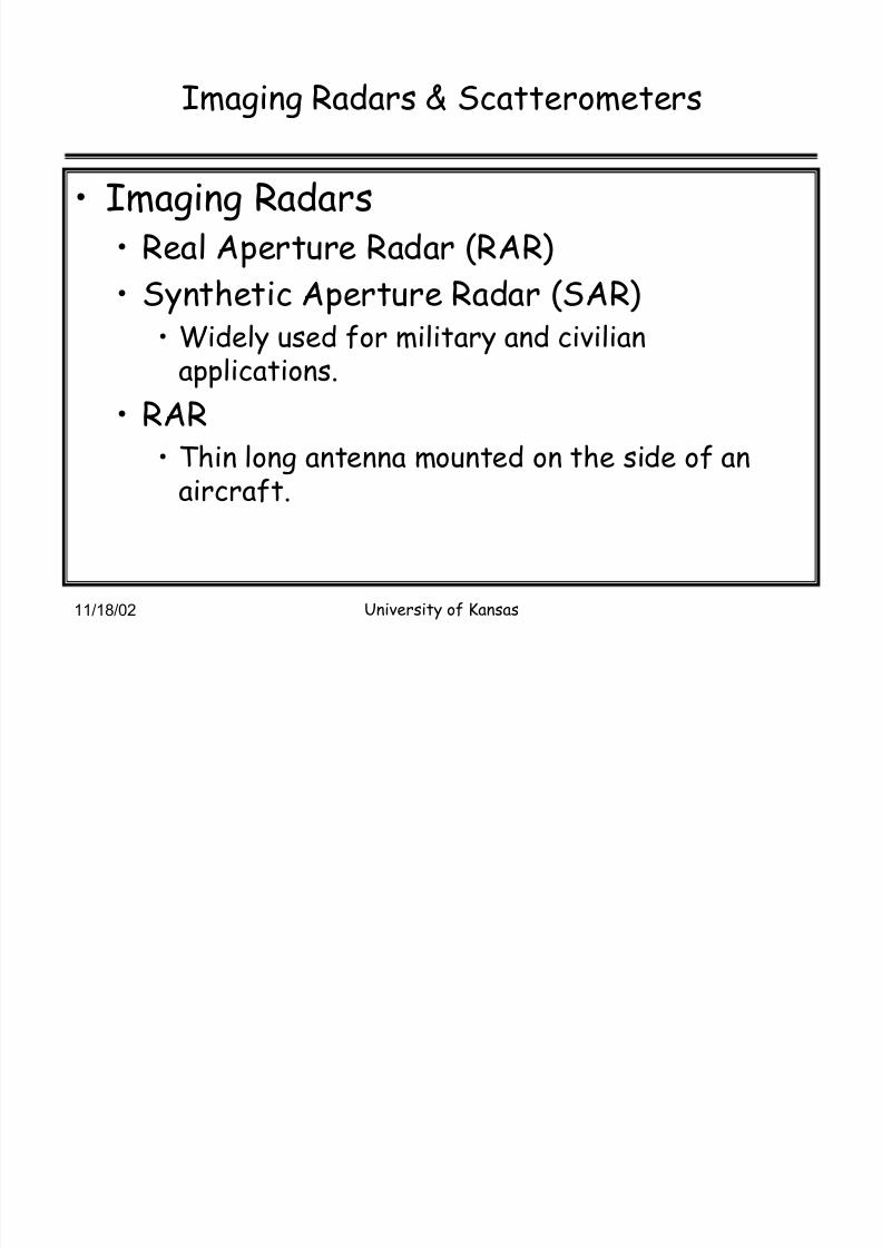
Imaging Radars & Scatterometers
Imaging Radars Real Aperture Radar (RAR)
Synthetic Aperture Radar (SAR) Widely used for military and civilian
applications.
RAR
Thin long antenna mounted on the side of anaircraft.

8/3/2019 Microwave Remote Sensing Intro Psd
http://slidepdf.com/reader/full/microwave-remote-sensing-intro-psd 51/78
11/18/02 University of Kansas
Imaging radars
RAR² Resolution is
determined by
antenna beamwidth inthe along trackdirection
² Pulse width in thecross-track direction
RAR geometry
factor weighting!
!!
k
D
Rk Rr
aa
P FH
)sin(2 U
XH
c
r c!

8/3/2019 Microwave Remote Sensing Intro Psd
http://slidepdf.com/reader/full/microwave-remote-sensing-intro-psd 52/78
11/18/02 University of Kansas
Imaging radars
For a radar operatingat f=10 GHz with a 3-mlong antenna in thealong track directionand 0.5 us pulse,resolution at 45 degreeincidence and range of10 km is given by
Assume k=0.8
m106
)45sin(2
105.0103
8003
03.01000008.0
100
106)45sin(2
105.0103
803
03.0100008.0
68
68
!!
!!
!
!!
!!
x x xr
m
xr
k m R
m
x x xr
m
xr
c
a
c
a
H
H
H
H

8/3/2019 Microwave Remote Sensing Intro Psd
http://slidepdf.com/reader/full/microwave-remote-sensing-intro-psd 53/78
11/18/02 University of Kansas
Imaging Radars: RAR
ResolutionRARs were used
until 1990s.
They are replaced
by SARs.Resolution should
1/20 about thedimensions of thetarget we want torecognize
MRS: vol. II, Ulaby, Moore and Fung
8/3/2019 Microwave Remote Sensing Intro Psd
http://slidepdf.com/reader/full/microwave-remote-sensing-intro-psd 54/78
11/18/02 University of Kansas
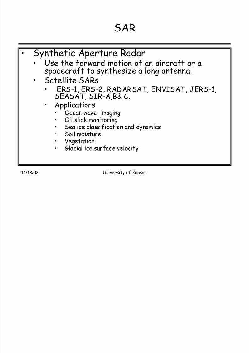
SAR
Synthetic Aperture Radar Use the forward motion of an aircraft or a
spacecraft to synthesize a long antenna. Satellite SARs
ERS-1, ERS-2, RADARSAT, ENVISAT, JERS-1,SEASAT, SIR-A,B& C. Applications
Ocean wave imaging Oil slick monitoring Sea ice classification and dynamics
Soil moisture Vegetation Glacial ice surface velocity

8/3/2019 Microwave Remote Sensing Intro Psd
http://slidepdf.com/reader/full/microwave-remote-sensing-intro-psd 55/78
11/18/02 University of Kansas
SAR
We can use a small physical antenna
For focused SAR resolution is
independent of Wavelength
Range
Best possible resolution is L/2 Where L= length of the physical antenna

8/3/2019 Microwave Remote Sensing Intro Psd
http://slidepdf.com/reader/full/microwave-remote-sensing-intro-psd 56/78
11/18/02 University of Kansas
RF Spectrum
Microwave Radiometry covers a range of frequencies.
1 GHz 10 GHz 100 GHz 1000 GHz
Soil
Moisture
1-3 GHz
Resolution /
aperture
Atmospheric
Temperature
54, 118 GHz
Accuracy
Atmospheric
Water Vapor
22, 24, 92, 150,
183 GHz
Accuracy
Sea Surface Salinity
1-3 GHz
Receiver sensitivity/
stability
Precipitation
11, 31,37,89 GHz
Frequent global
coverage
Atmospheric
Chemistry
190, 240, 640,
2500 GHz
High frequency
Sea Ice
37 GHz
Polar coverage
Ocean Surface Wind
19, 22 GHz
Polarimetry
Cloud Ice
325, 448, 643 GHz
High frequency
30 cm 3 cm 3 mm 0.3 mmP
R
L band S band C band X band Ku/K/Ka band Millimeter Submillimeter
Hartley, NASA

8/3/2019 Microwave Remote Sensing Intro Psd
http://slidepdf.com/reader/full/microwave-remote-sensing-intro-psd 57/78
11/18/02 University of Kansas
Microwave Radiometers³ theory
Planck·s Law of radiation
Where S(,T) =Intensity of
radiation in w/m2 T = temperature in Kelvins h = Planck·s constant, 6.625 ×
10-34 J·s c = velocity of propagation
m/s
k = Boltzmann constant,1.380 × 10-23 J/K
= wavelength, m
1
12),(
5
2
!kT
ch
e
hcT s
PP
TP
4
2),(
Approx
P
TP
P
ckT T S
kT ch
Jean s Ra yl eig h
!

8/3/2019 Microwave Remote Sensing Intro Psd
http://slidepdf.com/reader/full/microwave-remote-sensing-intro-psd 58/78
11/18/02 University of Kansas
Microwave Radiometer
At microwave frequencies radiationintensity is directly proportional to thetemperature.
For gray bodies² Pa = kT b B² k =Boltzman constant, B = bandwidth, Hz.
² T b = Brightness temperature, K² T b =e T phy
² e = Emissivity of the object or media

8/3/2019 Microwave Remote Sensing Intro Psd
http://slidepdf.com/reader/full/microwave-remote-sensing-intro-psd 59/78
11/18/02 University of Kansas
Microwave Radiometer
Two basic types of radiometers² Total power radiometer
Highest sensitivity
² Switching-type radiometers and its variants.
Typical total power radiometer
K T
K T
s MH z B
t imee g r at ion
band wid th B
where
B
T T
tot al
in
in
in
Tot al
2.0
500
1,6
int
TTTsysaltota
!(
!
!!
!
!
!
!(
X
X
X

8/3/2019 Microwave Remote Sensing Intro Psd
http://slidepdf.com/reader/full/microwave-remote-sensing-intro-psd 60/78
11/18/02 University of Kansas
Microwave Radiometer
Dicke or Switching-type radiometer² Any fluctuations in gain of the receiver will
reduce radiometer sensitivity.
² To eliminate system effects, Dickedeveloped switching type radiometer. It consists of switch and a synchronous
detector. The input is switched between theantenna and noise source. If the injected noisepower is equal to input signal power, the effectof gain fluctuations is eliminated.

8/3/2019 Microwave Remote Sensing Intro Psd
http://slidepdf.com/reader/full/microwave-remote-sensing-intro-psd 61/78
11/18/02 University of Kansas
Microwave Radiometer
Typical Dicke-type radiometer
in BXH total1.4TT
50% byreducedisn timeintegratio 50%,iscycledutytheIf
!

8/3/2019 Microwave Remote Sensing Intro Psd
http://slidepdf.com/reader/full/microwave-remote-sensing-intro-psd 62/78
11/18/02 University of Kansas
RF Radiometry Characteristics
Moden Radiometer
Digital processor
To eliminate down conversion process
digitalprocessor/
correlator
scan
low noise
amplifier
multiplexer/
spectrometer
detector/
digitizer mixer
LO
Receiver
Antenna
Hartley, NASA

8/3/2019 Microwave Remote Sensing Intro Psd
http://slidepdf.com/reader/full/microwave-remote-sensing-intro-psd 63/78
11/18/02 University of Kansas
Microwave Remote Sensing
Research and application ofmicrowave technology to remote
sensing of² Oceans and ice
² Solid earth and Natural hazards..
² Atmosphere and precipitation.² Vegetation and Soil moisture

8/3/2019 Microwave Remote Sensing Intro Psd
http://slidepdf.com/reader/full/microwave-remote-sensing-intro-psd 64/78
11/18/02 University of Kansas
Microwave Remote Sensing³ Ocean andIce
Winds
² Scatterometer.
Quickscat, Seawinds
² Polarimetric radiometer
Ocean topography² Radar altimeters
Ocean salinity
² AQUARIUS
Radiometer and radar combination.
² Radar to measure winds for correcting for the effectof surface roughness.

8/3/2019 Microwave Remote Sensing Intro Psd
http://slidepdf.com/reader/full/microwave-remote-sensing-intro-psd 65/78
11/18/02 University of Kansas
Ocean Vector Winds² Scatterometers
QuikScat Replacement mission for NSCAT, following loss of ADEOS Launch date: June 19, 1999SeaWinds
EOS instrument flying on the Japanese ADEOS II Mission
Launch date: December 14, 2002 ????Instrument Characteristics of QuikScat and SeaWinds Instrument with 120 W peak (30% duty) transmitter at 13.4
GHz, 1 m near-circular antenna with two beams at 46o and 54o
incidence angles
Scatterometers send microwave pulses to the
Earth's surface, and measure the power scattered
back. Backscattered power over the oceans
depends on the surface roughness, which in turn
depends on wind speed and direction.
QuikScat
SeaWinds
Advanced sensors± larger aperture
antennas.Passive polarimetric sensors.
Courtesy: Yunjin Kim, JPL
Ocean Topography Missions

8/3/2019 Microwave Remote Sensing Intro Psd
http://slidepdf.com/reader/full/microwave-remote-sensing-intro-psd 66/78
11/18/02 University of Kansas
Ocean Topography Missions
TOPEX/Poseidon and Jason-1
Joint NASA-CNES Program ± TOPEX/Poseidon launched on August 10, 1992
± Jason-1 launched on December 7, 2001
Instrument Characteristics
± Ku-band, C-band dual frequency altimeter
± Microwave radiometer to measure water vapor
± GPS, DORIS, and laser reflector for precise orbit determination
Sea-level measurement accuracy is 4.2 cm
TOPEX/Poseidon & Jason-1 tandem mission for high resolution oceantopography measurements
TO P EX/ P oseid on Ocean to po g r a ph y
o f the P acific Ocean dur ing E l Niño
and La Niña.
The most effective measurement of ocean currents
from space is ocean topography, the height of the sea
surface above a surface of uniform gravity, the geoid.
T he priority is to continue the measurement
with TOPEX/P oseidon accuracy
on a long-term basis for climate studies.
Courtesy: Yunjin Kim, JPL
Ocean Surface Topography Mission

8/3/2019 Microwave Remote Sensing Intro Psd
http://slidepdf.com/reader/full/microwave-remote-sensing-intro-psd 67/78
11/18/02 University of Kansas
Ocean Surface Topography Mission An Ex perimental Wide-Swath Altimeter
By adding an interferometric radar system to a conventional radar altimeter
system, a swath of 200 km can be achieved, and eddies can be monitored over
most of the oceans every 10 days. The design of such a system has
progressed, funded by NASA¶s Instrument Incubator Program. This
experiment is proposed to the next mission, OSTM (Ocean Surface
Topography Mission)
South AmericaCourtesy: Yunjin Kim, JPL
Global Ocean Salinity

8/3/2019 Microwave Remote Sensing Intro Psd
http://slidepdf.com/reader/full/microwave-remote-sensing-intro-psd 68/78
11/18/02 University of Kansas
Global Ocean Salinity
Aquarius (JPL, GSFC, CONAE)
ESSP-3 mission in the riskmitigation phase
First instrument to measure g lobal
ocean salinity
± Passive and active microwaveinstrument at L-band
± Resolution
Baseline 100km, Minimum200km
± Global coverage in 8 days
± Accuracy: 0.2 psu
± Baseline mission life: 3
years
1 week of salinity measurements from space
100 yrs of salinity measurements by shipCourtesy: Yunjin Kim, JPL

8/3/2019 Microwave Remote Sensing Intro Psd
http://slidepdf.com/reader/full/microwave-remote-sensing-intro-psd 69/78
11/18/02 University of Kansas
SRTM (Shuttle Radar Topography Mission)
C-band single pass interferometric SAR for
topographic measurements using a 60m
mast
DEM of 80% of the Earth¶s surface in a
single 11 day shuttle flight
± 60 degrees north and 56 degrees southlatitude
± 57 degrees inclination
225 km swath
WGS84 ellipsoid datum
JPL/NASA will deliver all the processed data
to NIMA by January 2003
Absolute accuracy requirements
± 20 m hori zontal
± 16 m vertical
The current best estimate of the SRTM
accuracy is
10 m horizontal and 8 m vertical
P artnership between N AS A and NIM A
(National Imag ery and Mapping Ag ency) X -band from German and Italian space
ag encies
Courtesy: Yunjin Kim, JPL
L band InSAR Technolog

8/3/2019 Microwave Remote Sensing Intro Psd
http://slidepdf.com/reader/full/microwave-remote-sensing-intro-psd 70/78
11/18/02 University of Kansas
L-band InSAR Technology
InSAR velocity difference indicates a 10%
increase in ice flow velocity from 1996 to
2000 on Pine Island Glacier
[Rignot et al., 2001]
Surface deformation due to Hector Mine
Earthquake using repeat-pass InSAR data
Interferometric Synthetic Aperture Radar
(InSAR) can measure surface
deformation (mm-cm scale) through
repeated observations of an area
L-band is preferable due to longer
correlation time due to longer
wavelength (24cm)
Solid Earth Science Working Group
recommended that
In the next 5 years, the new space
mission of highest priority for solid-
Earth science is a satellite
dedicated to InSAR measurementsof the land surface at L-band

8/3/2019 Microwave Remote Sensing Intro Psd
http://slidepdf.com/reader/full/microwave-remote-sensing-intro-psd 71/78
11/18/02 University of Kansas
Microwave Remote Sensing² Soil
Moisture.
HRDROS² Back-up ESSP mission for global soil moisture. L-band radiometer.
L-band radar.
- 98 .5 - 98 .0 - 97 .5
35.0
35.5
36.0
36.5
- 98 .0 - 97. 5 - 97 .0
0
10
20
30
40
50
Southern Great Plains Hydrology Experiment (SGP97)Surface Soil Moisture Derived From Remotely Sensed Microwave Data
June 30 July 1
July 2 July 3
Soil Moisture (%)
L a t i t u d e ( D e g r e e s )
Longitude (Degrees)
50
40
30
20
10
0
35.0
35.5
36.0
36.5
37.0
Chickasha
ElReno
Lamont
OklahomaCity
Chickasha
ElReno
Lamont
OklahomaCity
Chickasha
ElReno
Lamont
OklahomaCity
Chickasha
ElReno
Lamont
OklahomaCity
June 30
NASA LandSurface Hydrology Program
Courtesy: Tom Jackson, USDA
SGP¶97
Radar
Pol: VV, HH & HV
Res ± 3 and 10 km
Radiometer
Pol: H, V
Res =40 km,
dT= 0.64º K

8/3/2019 Microwave Remote Sensing Intro Psd
http://slidepdf.com/reader/full/microwave-remote-sensing-intro-psd 72/78
11/18/02 University of Kansas
Salient Features
N AS A E SSP mi ssion
First 94 GH z r ad ar s pace bor ne s y stem
C o-manif ested with C A LIPS O on Del t a l aunch vehicl e
Flies F or mat ion with the EOS C on stell at ion
Current l aunch d ate: A pr il 2004
O per at ional lif e: 2 years
P art nership with DoD ( on-or bit o p s), DoE ( valid at ion ) and CS A ( r ad ar d evel o pment)
Science
Mea sure the vert ical str uct ure o f cl oud s and quant ify their ice and water content
I m prove weather predict ion and cl ar ify climat ic processes.
I m prove cl oud inf or mat ion f rom other satellite s y stem s, in part icul ar those o f Aqua
Invest ig ate the wa y aerosol s a ff ect cl oud s and precipit at ion
Invest ig ate the ut ilit y o f 94 GH z r ad ar to ob serve and quant ify precipit at ion , in the conte xt o f cl oud pro pert ies, f rom s pace
CloudSAT
Microwave Remote Sensing² Atmosphere and
Precipitation
Courtesy: Yunjin Kim, JPL

8/3/2019 Microwave Remote Sensing Intro Psd
http://slidepdf.com/reader/full/microwave-remote-sensing-intro-psd 73/78
11/18/02 University of Kansas
Earth Science and RF Radiometery
Microwave
Radiometry
Applications.
Ocean surface wind
Soil moisture
Sea surface temperature/
Sea surface salinity
Atmospheric temperature, humidity, and clouds
Precipitation
Atmospheric chemistry
Hartley, NASA

8/3/2019 Microwave Remote Sensing Intro Psd
http://slidepdf.com/reader/full/microwave-remote-sensing-intro-psd 74/78
11/18/02 University of Kansas
Conclusions
A brief overview of microwave remotesensing principles and applications.
Opportunities for research andeducation.² Science
² Technology

8/3/2019 Microwave Remote Sensing Intro Psd
http://slidepdf.com/reader/full/microwave-remote-sensing-intro-psd 75/78
11/18/02 University of Kansas
SAR³Principle
SAR can explained using the conceptof a matched filter or antenna array.
Ro

8/3/2019 Microwave Remote Sensing Intro Psd
http://slidepdf.com/reader/full/microwave-remote-sensing-intro-psd 76/78
11/18/02 University of Kansas
SAR³ Principle
Unfocussed SAR No phase corrections are made.
Ro
r
2
48
4
82
4
4
2
22
2
0
P
T
P
TJJN
P
TJ
P
TJ
o
o
o N d
o
o
N
o
o
Rl
R
l
R
l R
l R R
R
R
e
e!!
}¹ º
¸©ª
¨!
!
!
8/3/2019 Microwave Remote Sensing Intro Psd
http://slidepdf.com/reader/full/microwave-remote-sensing-intro-psd 77/78
11/18/02 University of Kansas
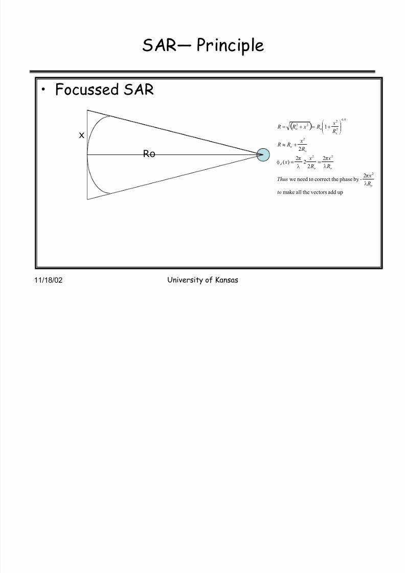
SAR³ Principle
Focussed SAR
Ro
x
upaddvectorstheallmake
2- by phaseecorrect thtoneedwe
2
22
2)(
2
1
2
22
2
5.0
2
222
to
R
xThu s
R
x
R
x x
R
x R R
R
x R x R R
o
oo
d
oo
o
oo
P
T
P
T
P
TJ !!
}
¹¹ º
¸©©ª
¨!!

8/3/2019 Microwave Remote Sensing Intro Psd
http://slidepdf.com/reader/full/microwave-remote-sensing-intro-psd 78/78
11/18/02 University of Kansas
SAR³ Principle
Resolution
22r ,resolutiontrack Along
&5.0 ,
bygivenare beamwidthdB-4
44.0,Leff length,of aperturesyntheticFor
88.0 bygivenisD,length,of aperture
realdilluminateuniformlyanof beamwidthdB-3The
a
ar
as
ar
D
L
R R
D
R L
L D
L
D
f e
ooa s
oe f
e f
a s
e f
!!!
!!!
!
!
P F
PP F
P F
P F
P F