mid-air pointing on ultra-walls
TRANSCRIPT

HAL Id: hal-01184544https://hal.inria.fr/hal-01184544
Submitted on 15 Aug 2015
HAL is a multi-disciplinary open accessarchive for the deposit and dissemination of sci-entific research documents, whether they are pub-lished or not. The documents may come fromteaching and research institutions in France orabroad, or from public or private research centers.
L’archive ouverte pluridisciplinaire HAL, estdestinée au dépôt et à la diffusion de documentsscientifiques de niveau recherche, publiés ou non,émanant des établissements d’enseignement et derecherche français ou étrangers, des laboratoirespublics ou privés.
Mid-air Pointing on Ultra-WallsMathieu Nancel, Emmanuel Pietriga, Olivier Chapuis, Michel
Beaudouin-Lafon
To cite this version:Mathieu Nancel, Emmanuel Pietriga, Olivier Chapuis, Michel Beaudouin-Lafon. Mid-air Pointingon Ultra-Walls. ACM Transactions on Computer-Human Interaction, Association for ComputingMachinery, 2015, 22 (5), pp.21:1–21:62. �10.1145/2766448�. �hal-01184544�

21
Mid-air Pointing on Ultra-Walls
MATHIEU NANCEL, Universite Paris-Sud & CNRS, Inria; University of Canterbury; University of Waterloo
EMMANUEL PIETRIGA, Inria, Universite Paris-Sud & CNRS; Inria Chile
OLIVIER CHAPUIS, Universite Paris-Sud & CNRS, Inria
MICHEL BEAUDOUIN-LAFON, Universite Paris-Sud & CNRS, Inria
Ultra-high-resolution wall-sized displays (“ultra-walls”) are effective for presenting large datasets, but their
size and resolution make traditional pointing techniques inadequate for precision pointing. We study mid-airpointing techniques that can be combined with other, domain-specific interactions. We first explore the limits
of existing single-mode remote pointing techniques and demonstrate theoretically that they do not support
high-precision pointing on ultra-walls. We then explore solutions to improve mid-air pointing efficiency:a tunable acceleration function and a framework for dual-precision techniques, both with precise tuning
guidelines. We designed novel pointing techniques following these guidelines, several of which outperform
existing techniques in controlled experiments that involve pointing difficulties never tested prior to thiswork. We discuss the strengths and weaknesses of our techniques to help interaction designers choose the
best technique according to the task and equipment at hand. Finally, we discuss the cognitive mechanisms
that affect pointing performance with these techniques.
Categories and Subject Descriptors: H.5.2 [Information Interfaces and Presentation]: User Interfaces, Input Devices and Strategies.
General Terms: Design, Performance, Experimentation
Additional Key Words and Phrases: pointing, dual-precision, large displays, ultra-high resolution
ACM Reference Format:Mathieu Nancel, Emmanuel Pietriga, Olivier Chapuis, and Michel Beaudouin-Lafon, 2015. Mid-air Pointing on Ultra-Walls. ACMTrans. Comput.-Hum. Interact. 22, 5, Article 21 (August 2015), 62 pages.DOI: http://doi.acm.org/10.1145/2766448
1. INTRODUCTION
Ultra-high-resolution wall-sized displays, or ultra-walls for short, are a new generation of wall-sized dis-plays made of a mosaic of LCD panels [Nam et al. 2009; Nam et al. 2010]. With about 100 pixels per inchand more than 100 million pixels overall, they have three times the pixel density and ten times the resolutionof the previous generation of projection-based, very-high-resolution wall-sized displays. Such high densityand resolution support the display of large datasets with a high level of detail while retaining context, andenable the juxtaposition of data of various types [Andrews et al. 2010], including small text that is perfectlylegible from up close.
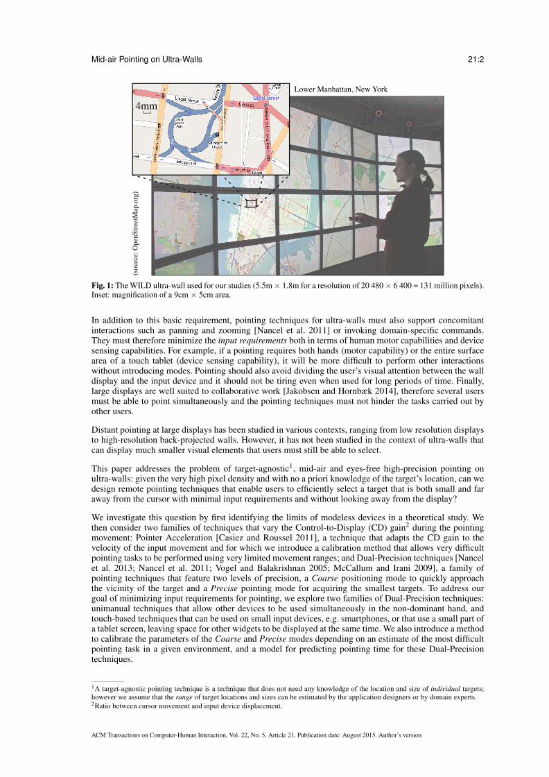
These displays are well suited to the visualization of, e.g., very large maps and complex networks (Figure 1),complex molecule simulations, or astronomy imagery with associated metadata from astronomical catalogs[Beaudouin-Lafon et al. 2012]. The combination of large size and high resolution affords a natural form ofmultiscale interaction: simply by walking, a user can smoothly transition from an overview of the wholedisplay when standing at a distance to the fine details of a specific area by getting up close [Ball et al. 2007;Yost et al. 2007; Liu et al. 2014; Jakobsen and Hornbæk 2014]. It is thus critical that users be able to pointat very small objects on the screen efficiently, whether they are standing far away from the display or withinarm’s reach [Vogel and Balakrishnan 2005].
This work is supported by the Region Ile-de-France/Digiteo grant 2008-25D “WILD” and by the French National Research Agencygrant ANR-10-EQPX-26-01 “DIGISCOPE”.
Authors’ addresses: M. Nancel <[email protected]>: University of Waterloo, Canada. E. Pietriga <[email protected]>& O. Chapuis <[email protected]> & M. Beaudouin-Lafon <[email protected]>: Universite Paris Sud, 91405 ORSAY Cedex, France.
c© ACM, 2015. This is the author’s version of the work. It is posted here by permission of ACM for your personal use. Not forredistribution. The definitive version was published in ACM Transactions on Computer-Human Interaction, ToCHI, 22(5), Article No.21, 62 pages, August 2015. DOI: http://doi.acm.org/10.1145/2766448
ACM Transactions on Computer-Human Interaction, Vol. 22, No. 5, Article 21, Publication date: August 2015. Author’s version
Mid-air Pointing on Ultra-Walls 21:2
Lower Manhattan, New York
(sou
rce:
Ope
nStre
etM
ap.o
rg)
4mm
Fig. 1: The WILD ultra-wall used for our studies (5.5m× 1.8m for a resolution of 20 480× 6 400 = 131 million pixels).Inset: magnification of a 9cm × 5cm area.
In addition to this basic requirement, pointing techniques for ultra-walls must also support concomitantinteractions such as panning and zooming [Nancel et al. 2011] or invoking domain-specific commands.They must therefore minimize the input requirements both in terms of human motor capabilities and devicesensing capabilities. For example, if a pointing requires both hands (motor capability) or the entire surfacearea of a touch tablet (device sensing capability), it will be more difficult to perform other interactionswithout introducing modes. Pointing should also avoid dividing the user’s visual attention between the walldisplay and the input device and it should not be tiring even when used for long periods of time. Finally,large displays are well suited to collaborative work [Jakobsen and Hornbæk 2014], therefore several usersmust be able to point simultaneously and the pointing techniques must not hinder the tasks carried out byother users.
Distant pointing at large displays has been studied in various contexts, ranging from low resolution displaysto high-resolution back-projected walls. However, it has not been studied in the context of ultra-walls thatcan display much smaller visual elements that users must still be able to select.
This paper addresses the problem of target-agnostic1, mid-air and eyes-free high-precision pointing onultra-walls: given the very high pixel density and with no a priori knowledge of the target’s location, can wedesign remote pointing techniques that enable users to efficiently select a target that is both small and faraway from the cursor with minimal input requirements and without looking away from the display?
We investigate this question by first identifying the limits of modeless devices in a theoretical study. Wethen consider two families of techniques that vary the Control-to-Display (CD) gain2 during the pointingmovement: Pointer Acceleration [Casiez and Roussel 2011], a technique that adapts the CD gain to thevelocity of the input movement and for which we introduce a calibration method that allows very difficultpointing tasks to be performed using very limited movement ranges; and Dual-Precision techniques [Nancelet al. 2013; Nancel et al. 2011; Vogel and Balakrishnan 2005; McCallum and Irani 2009], a family ofpointing techniques that feature two levels of precision, a Coarse positioning mode to quickly approachthe vicinity of the target and a Precise pointing mode for acquiring the smallest targets. To address ourgoal of minimizing input requirements for pointing, we explore two families of Dual-Precision techniques:unimanual techniques that allow other devices to be used simultaneously in the non-dominant hand, andtouch-based techniques that can be used on small input devices, e.g. smartphones, or that use a small part ofa tablet screen, leaving space for other widgets to be displayed at the same time. We also introduce a methodto calibrate the parameters of the Coarse and Precise modes depending on an estimate of the most difficultpointing task in a given environment, and a model for predicting pointing time for these Dual-Precisiontechniques.
1A target-agnostic pointing technique is a technique that does not need any knowledge of the location and size of individual targets;however we assume that the range of target locations and sizes can be estimated by the application designers or by domain experts.2Ratio between cursor movement and input device displacement.
ACM Transactions on Computer-Human Interaction, Vol. 22, No. 5, Article 21, Publication date: August 2015. Author’s version

Mid-air Pointing on Ultra-Walls 21:3
We designed a variety of pointing techniques that can be used eyes-free and with minimum input require-ments and we evaluated them in four controlled experiments. We find that our calibration methods makeit possible to use both Pointer Acceleration and Dual-Precision techniques at a distance for pointing taskswith a high index of difficulty. Given these results we present a set of design guidelines to select whichtechniques and input methods can be used depending on the available input devices and the required point-ing difficulty. Finally we discuss the cognitive costs associated with varying the CD gain during a pointingtask.
2. RELATED WORK
A large corpus of techniques and devices have been developped and studied for mid-air pointing. We reviewthem according to the way they map user input to cursor movements. First we briefly review pointingtechniques that use velocity control (first-order control). We then consider position control (zeroth-ordercontrol) mid-air pointing techniques by distinguishing between absolute and relative mappings, and finallywe report on “hybrid” techniques that feature both types of controls.
2.1. Rate-based mid-air pointing techniques
Techniques that map relative device motion to cursor displacements can be based on position control orrate/velocity control (zeroth or first order of control). [Rutledge and Selker 1990] designed and evaluatedtransfer functions for isometric pointing joysticks at the center of the keyboard and found it faster thana normal mouse for intermixed pointing and keyboard tasks in a desktop environment. However they donot report the mouse gain nor whether it was speed-dependent. More recent studies [Campbell et al. 2008;Natapov et al. 2009] and our own tests show that techniques based on rate control are faster and morecomfortable for coarse pointing across large distances, but perform poorly during the final precise pointingphase. [MacKenzie and Jusoh 2001] compared a regular mouse with a gyroscopic mouse3 held on a tableand then in mid-air, and to a handheld isometric joystick. The task was performed 1.52m away from a 15”screen. The joystick and the gyro-mouse held in mid-air performed poorly compared to the mice. Morerecently, [Casiez and Vogel 2008] evaluated rate-controlled pointing techniques with isometric and elasticdevices and with several CD gains, but did not evaluate them against position-controlled techniques.
2.2. Position-based absolute mid-air pointing techniques
Absolute pointing devices or techniques map an input state, e.g. the location and orientation of a hand-held device, to a cursor location on the display. Techniques based on the absolute position of the inputdevice include the family of ray-casting techniques, also called “laser pointing” [Myers et al. 2002; Oh andSturzlinger 2002; Olsen and Nielsen 2001]. These techniques extend the user’s finger, arm, or hand-helddevice with an imaginary ray whose intersection with the display defines the cursor position. [Kopper et al.2010] and [Jota et al. 2010] formulate angular-based models of pointing time that fit ray-casting performancebetter than Fitts’ law.
While intuitive, ray casting is essentially angle-based and thus degrades quickly with distance to the displaybecause hand tremor and involuntary motion due to fatigue are amplified as the user is farther away fromthe display surface [Myers et al. 2002; Oh and Sturzlinger 2002]. It is therefore not suitable for small targetson ultra-walls. [Olsen and Nielsen 2001] adapted existing interaction techniques to the limitations of thistechnology. Both [Chen and Davis 2000] and [Oh and Sturzlinger 2002] designed collaborative pointingdevices based on laser pointers, enabling several users to interact with the display simultaneously. The latteralso compared a laser pointer with a conventional mouse in a pointing task. The laser pointer performedsignificantly worse than the mouse on a 1.83m × 1.22m low-resolution back-projected screen, but waspreferred by users.
[Myers et al. 2002] studied the effect of human body limitations on laser pointing. They compared thepointing performance of a laser pointer with that of a regular mouse, a touch-sensitive SmartBoardTM andSemantic snarfing. With the latter, users point with a stylus on a handheld device that displays a copy of aregion from the main screen. The technique requires users to look at the handheld device, creating a divisionof attention. Direct input standing in front of the SmartBoard was the most efficient technique, followed bySemantic Snarfing. Laser pointer was the worst technique. Except for the SmartBoard which required directcontact, other conditions were performed seated about 1.52m away from the display.
Another ray-casting technique consists in holding a device at arm-length in front of the eyes so that the targetis aligned with the tip of the device [Pierce et al. 1997]. The technique is interesting as it resembles aiming,
3A mouse that uses gyroscopic sensors, also called gyro-mouse.
ACM Transactions on Computer-Human Interaction, Vol. 22, No. 5, Article 21, Publication date: August 2015. Author’s version

Mid-air Pointing on Ultra-Walls 21:4
but our own tests [Nancel 2012, App. B] revealed its limitations: it is more tiring and less precise than laserpointing, causes visual occlusion, and requires users to repeatedly switch between two very different focallengths.
Some techniques use absolute input but focus more on the interaction vocabulary than on pointing perfor-mance. For example, VisionWand [Cao and Balakrishnan 2003] tracks the position of a wand in 3D usingtwo low-cost cameras. The two ends of the wand have different colors and can be distinguished by thevision system. While it does not improve distant pointing performance, it enables interactions such as tap,tilt, flip and rotate gestures. Other works use vision-based techniques to enable freehand pointing. [Nickeland Stiefelhagen 2003] recognize pointing gestures with two cameras. They introduce new pointing tech-niques using information such as head and forearm orientation, but focus on the recognition of relevantgestures among a sequence of arbitrary movements rather than precision of pointing gestures. With ShadowReaching [Shoemaker et al. 2007], users reach distant objects through the shadow of their body cast on thedisplay surface by a light source. Because of projection perspective, the regions that can be reached dependon both the setup and the user’s distance to the display. As with laser pointing, the accuracy of this techniquedecreases with distance to the display.
Absolute mappings can also be used in combination with a small hand-held device. With the Touch projector[Boring et al. 2010], users manipulate objects located on a distant display using a smartphone (iPhone)through a live video feed showing that display.
Finally, the Wiimote and other game controllers have also been studied as general-purpose pointing devices.[Campbell et al. 2008] evaluated a Wiimote operated as a zero-order or first-order pointing device, and foundthat participants were roughly 2.5 times faster in the zero-order condition. [Natapov et al. 2009] comparedremote pointing with a Wiimote, a classic gamepad’s joystick, and a mouse operated on a desk as baseline.They found that the mouse had the best throughput, followed by the Wiimote and the joystick, and reportedthat hand tremor and small movements greatly affected accuracy in the Wiimote condition for small targets.
2.3. Position-based relative mid-air pointing: Pointer Acceleration
Relative position-based control maps the user’s motion to the movements of the cursor, regardless of theoriginal location of that motion. A wide variety of devices and techniques, including the widespread mouseand trackpad for desktop computers, use this technique. Jellinek et al. describe and explore a design space ofsuch mappings [Jellinek and Card 1990] for mice on desktop computers. They found that varying gains werepreferred but did not improve performance over fixed gains in their experimental setup. In this subsection weonly describe relative pointing techniques that use a transfer function between the velocity of the user inputand that of the cursor (‘Hydromatic-glide’ in [Jellinek and Card 1990]) because constant gains have seldombeen used in the literature for mid-air pointing. Indeed, as we demonstrate later in this article, constant-gaintransfer functions result in insufficient range and precision to be usable on most large displays at a distance.
Pointer Acceleration consists in varying the ratio between the velocities of the cursor and the input move-ment4, based on the assumption that users perform faster movements when they want the cursor to movefar away and that they perform slower movements when precisely adjusting the cursor’s position. PointerAcceleration is used by all major operating systems. [Casiez and Roussel 2011] have measured the velocitytransfer functions of these systems and showed that they varied significantly in shape, but not necessarily intheir input and output domains.
Despite the widespread use of Pointer Acceleration, there is very little literature on how to design effectivetransfer functions for specific input and output systems such as ultra-walls. The PRISM technique [Freeset al. 2007] and its subsequent refinements [Konig et al. 2009; Gallo and Minutolo 2012] are among thevery few that have documented their transfer functions. However, they were designed to support implicitabsolute-to-relative transfer functions and, as we show later in this paper, this approach does not scale to thehigh indices of difficulty that users of ultra-walls are exposed to.
2.4. Position-based “hybrid” mid-air pointing techniques
Some techniques, rather than making the whole range of CD gains accessible through a continuous transferfunction, provide users with two pointing modes, usually an absolute one for large-amplitude movementsand a relative one for slower, more precise movements. With HybridPointing [Forlines et al. 2006], userscan reach distant objects by switching from absolute to relative pointing by pressing with the pen used for
4We refer to this ratio as the Control-to-Display (CD) gain.
ACM Transactions on Computer-Human Interaction, Vol. 22, No. 5, Article 21, Publication date: August 2015. Author’s version

Mid-air Pointing on Ultra-Walls 21:5
pointing inside a trailing widget that follows the cursor. The technique requires direct contact of the penwith the display surface, which makes it impossible to operate in mid-air.
ARC-Pad [McCallum and Irani 2009] uses a touch-sensitive mobile device for cursor positioning on largedisplays. When the user taps the screen, the position of the tap is mapped to the entire display, enablingcoarse but fast repositioning of the cursor. When the user drags on the touch surface, the finger movementsare interpreted as relative input, allowing precise adjustments to the cursor’s position.
[Vogel and Balakrishnan 2005] use a high-precision 3D motion tracking system to develop and evalu-ate three techniques: pure ray casting, relative pointing with clutching, and ray-to-relative pointing, whichcombines absolute and relative pointing using two different hand postures. We adapted the latter to ourenvironment and tested it in the experiment described in Section 5.
3. LIMITATIONS OF THE HUMAN SENSORY-MOTOR SYSTEM FOR MID-AIR POINTING
Ultra-walls are powerful interactive platforms both in terms of display capacity and input modalities [Nancel2012; Beaudouin-Lafon et al. 2012]. Combined with computer clusters and appropriate software, dozens ofhigh-density displays can be tiled so as to be used as a single, unified surface [Pietriga et al. 2011; Schwarzet al. 2012]. At the same time, advances in input sensors make it easier and cheaper to use input channelssuch as mid-air gestures [Nancel et al. 2011], whole-body input [Wagner et al. 2013] and multi-sensordevices such as smartphones and tablets in a collaborative context [Chapuis et al. 2014].
These technological advances actually surpass the sensory-motor capabilities of the human body. For exam-ple, [Aceituno et al. 2013] showed that the input resolution of pointing devices exceeds the motor resolutionof most users, and recent display technology such as Apple’s Retina displays reach and sometimes go be-yond human visual acuity. In this section we analyze the limits of the human visual and motor systems inthe context of mid-air interaction on large displays. We later use the results of this analysis in the design ofmid-air pointing gestures adapted to ultra-walls.
3.1. Limitations of the human visual system
The largest ultra-walls range from 5-meter to 10-meter wide and 1.8-meter to 3-meter high. These sizes areuseful to display large quantities of information, especially when coupled with high pixel densities. Even ata distance, they can be visually larger than desktop screens while allowing fine details, and therefore smalltargets, to be displayed.
There is a limit distance beyond which a user with normal vision can no longer perceive a target. The angularwidth of a target seen by a user at a distance D from the display is
β = tan−1(
A+ w2
D
)− tan−1
(A− w
2D
)(1)
where w is the target’s width and A the distance between the target and the orthogonal projection of theuser’s point of view on the display5, i.e. the point directly facing the user (point P in Fig. 2-a). Accordingto the theory of visual acuity, β must be greater than or equal to 1’ of arc ( 1
60◦) for a “normal” user (20/20
vision) to be able to distinguish the target [Ware 2004], and greater than or equal to 5’ of arc ( 112◦) to be
readable [Vogel and Balakrishnan 2005]. Solving this inequality for D results in a half disc of diameterØ = w/ tan(β )◦ centered at
(A = 0,D = Ø
2
).
Fig. 2-b shows the inequality plot for a user with 20/20 vision and targets of 4 mm and 10 mm. The plotshows that the user must stand closer than respectively 13.8 m and 34.4 m from the screen to be able todistinguish these targets directly facing him, and closer than respectively 2.8 m and 6.9 m to read them.Another reading of this plot is that regardless of the user’s distance to the display, 4 mm targets further awaythan 6.9 m from point P (the point facing the user) and 10 mm targets further away than 17.2 m from pointP cannot be perceived accurately by users with normal vision. Similarly text labels cannot be read if theyare further away than 1.4 m (4mm or 11-point text) and 3.4 m (10mm or 28-point text) from P.
Using the same formula, we can compute the smallest pixel size w that can be accurately perceived at agiven distance by a user facing the screen:
w = 2×D× tan(
β
2
)(2)
5Reduced to a single point for simplicity.
ACM Transactions on Computer-Human Interaction, Vol. 22, No. 5, Article 21, Publication date: August 2015. Author’s version

Mid-air Pointing on Ultra-Walls 21:6
(a) (b)
D
A
β
P w
Visibleβ=1/60º
Decipherableβ=1/12º
A (m)
D (
m)
15
20151050
10
5
0
20
(P')
30
25
35w=10 mm
A (m)
D (
m)
15
20151050
10
5
0
20
(P')
30
25
35w=4 mm
Fig. 2: (a) The user looks at a target of width w at an offset A from the orthogonal projection P of his eyes on the displayand from a distance D to the display. (b) The possible values of D for which a 4-mm target (left) and 10-mm target(right) can be accurately perceived (blue) and read (red) for a given distance A. As an example, the thick blue line onthe Y axis represents the range of distances at which the user can accurately distinguish pixels that are A = 6 m awayfrom his projected point of view P.
Using a conservative minimal distance D of 2 m and the readability limit of 112◦, this smallest size is w =
2.9 mm (or about 8 points for text). Smaller targets will require users to step forward to be accurately read.In the following, we use w = 4 mm as our smallest target width at 2 meter distance in order to evaluate thehardest mid-air pointing tasks that can be performed on ultra-walls. We chose a value slightly larger than2.9 mm to account for non-perfect vision, even when corrected.
Note that the limits of visual acuity do not invalidate the use of high-resolution large displays. Large displaysimprove collaboration and performance by allowing users to navigate physically [Ball et al. 2007]. Theyoutperform desktop computers for interactive tasks that can take advantage of the high pixel density ofultra-walls to display numerous small textual elements simultaneously [Liu et al. 2014]. [Yost et al. 2007]showed that the advantages of high pixel density are not limited by visual acuity. In particular, users weremore efficient and sometimes more accurate performing information visualization tasks on a display with apixel density exceeding visual acuity. [Tan et al. 2006] showed that regardless of visual angles, physicallylarge displays improve performance and precision for spatial tasks such as mental rotation, 3D navigationand mental map formation and memory. They hypothesize that large displays improve the users’ sense ofimmersion and presence and help them to use more optimal cognitive strategies.
3.2. Limitations of the human motor system
Over the past ten years, a number of physical input devices have been explored for pointing on large displays.As with desktop pointing, some techniques map the absolute position of the input device to the cursor’sposition, while others use its relative motion to control cursor displacements.
We are specifically interested in techniques that allow users to point from afar while standing or walkingin front of the display. Therefore we do not consider direct techniques that use a pen [Guimbretiere et al.2001] or direct touch [Buxton et al. 2000; Streitz et al. 1999] since they require users to stand within physicalreach of the display. Similarly, we do not consider systems that can work from afar but that require usersto sit at a table. For example, [Malik et al. 2005] introduce a vision-based system for whole-hand gesturalinteractions performed on a constrained tabletop area. The system supports precise target acquisition on aback-projected wall-sized display from afar using asymmetric interactions, but is designed for users seatedat a table. The rest of this section focuses on techniques that can be used in mid-air.
Position-based pointing techniques require a transfer function [Nancel et al. 2013] mapping input motion,as captured by the device, to cursor motion. The most common transfer function uses a Control-to-Display(CD) gain, defined as the ratio between cursor movement, generally measured as a linear distance6 andinput variation, expressed in the same unit. Multiplying the magnitude of the input device motion by theCD gain therefore gives the amplitude of cursor motion. Since a gain is by definition without unit, bothinput and output amplitudes must be expressed in the same units. However, some techniques or devicesmap input and output of different natures. For example, a gyroscopic mouse transforms angular movementsinto cursor translations. In such cases the “gain” has a unit, i.e. meters per degree in this example. For thesake of simplicity and since the same computational mechanism is applied whether the multiplier has a unitor not, we also refer to such values as CD gains. In the rest of the paper we indicate the units of gains onlywhen input and output are of different types.
6Note however that ray-casting techniques can be modeled as an angular-to-angular mapping of gain 1.
ACM Transactions on Computer-Human Interaction, Vol. 22, No. 5, Article 21, Publication date: August 2015. Author’s version

Mid-air Pointing on Ultra-Walls 21:7
The value of the CD gain is not necessarily constant. Most operating systems vary the CD gain with inputvelocity, based on the principle that slow input motion occurs when precise cursor movements are intendedand that fast input motion occurs when coarse cursor movements are intended. This specific velocity-basedrelative technique is called Pointer Acceleration [Casiez and Roussel 2011]. However, the literature aboutPointer Acceleration functions is rather scarce, and existing functions were not designed for ultra-walls.Jellinek et al. argued that Pointer Acceleration (and all types of ‘Powermice’ in general [Jellinek and Card1990]) does not improve pointing performance, and is only preferred because it minimizes the device foot-print. However their experimental setup was limited to mice and desktop computers. This hypothesis re-mains to be validated on a wall-sized display.
The set of relative pointing techniques and devices that can work for ultra-walls can be refined by analyzingthe devices’ characteristics using the framework defined by [Casiez et al. 2008]. This framework providesformulae to compute upper and lower bounds for the CD gain, noted CDmax and CDmin. A gain belowCDmin requires clutching, which is believed to decrease performance. A gain above CDmax causes precisionproblems because of hand tremor and/or device quantization. If CDmin is greater than CDmax (Fig. 3), theseproblems are compounded: any CD gain will trigger at least one of them, or both.
(a) (b)
CDmax
CDmin Precisionproblems
Clutchproblems CD gain
CDmax
CDmin
Precisionproblems
Clutchproblems CD gain
Fig. 3: (a) Problems that arise when the CD gain value is lower than CDmin or larger than CDmax. (b) When CDmin isgreater than CDmax, no CD gain value can avoid both problems.
These formulae use an estimate of the minimum target width (Wmin), the maximum distance between targets(Amax), the pixel density of the display (Resscreen), the device’s morphological characteristics —operatingrange (OR) and input resolution (Resdevice)— and human motor precision (Reshand). All these parametersmust be expressed in the same physical unit, e.g. millimeters or inches, but not in pixels because displaypixels and device ticks (or minimal input) often have different physical sizes: a CD gain used with a 600 dpimouse on an 80 PPI screen should have the same effect as a 1600 dpi mouse on a 100 PPI screen.
The formulae from [Casiez et al. 2008] use Resdevice and Resscreen expressed as densities in pixels perinches (ppi), which forces all other parameters to be expressed in inches, or to convert units. We use themultiplicative inverse of these measures instead, i.e., the physical size of pixels, or Point Size (PS), so thatthey can be expressed in any length unit: PSdevice and PSscreen represent the point size of the input anddisplay devices, respectively7. Using these conventions, the formulae from [Casiez et al. 2008] are rewrittenas follows:
CDmin =Amax
OR(3)
CDmax = min(CDqmax,CDlmax) (4)
CDlmax =Wmin
Reshand(5)
CDqmax =Resdevice
Resscreen=
PSscreen
PSdevice(6)
CDmin (Eq. (3)) is the ratio between the largest amplitude of a pointing task on a given display (Amax) and thelargest device input movement (OR); it represents the minimum CD gain below which clutching is boundto occur. If the CD gain is lower than this value, the input movement needed to make the cursor travel adistance of Amax is larger than the operating range of the technique / device, resulting in the need to clutch.
Allowing clutching reduces CDmin but has a cost. For example, clutching can be an effective pointingstrategy on a small touch area [Nancel et al. 2015; Beaudouin-Lafon et al. 2014] but this result mightnot hold when performing an angular gesture using the whole arm. If we define c as the maximum numberof clutches that should happen in a normal pointing task, then the cursor must go through the maximum
7Note that Reshand should also be renamed PShand for it represents a “point size”, i.e. the smallest input that users can perform. Howeversince we do not change its definition, as opposed to PSscreen and PSdevice, we keep the same name for consistency with [Casiez et al.2008].
ACM Transactions on Computer-Human Interaction, Vol. 22, No. 5, Article 21, Publication date: August 2015. Author’s version

Mid-air Pointing on Ultra-Walls 21:8
pointing amplitude Amax in less than c + 1 movements of amplitude OR. We can thus relax Eq. (3) asfollows:
CDmin =Amax
(c+1)OR(7)
Note that clutching can only occur with relative controls. An absolute control maps OR to at least Amax,corresponding to c = 0. Thus, precision problems can occur but not clutching problems.
CDlmax (Eq. (5)), i.e. the maximum CD gain given limb precision, is the ratio between the smallest targetsize for a given task (Wmin) and the smallest human input (Reshand); it represents the maximum CD gainbeyond which human precision problems start to occur, i.e., the minimal input that can be used to keep thecursor stable within the smallest targets. If the CD gain is higher than this value, acquiring targets of sizeWmin requires more precision than normally available.
CDqmax (Eq. (6)), i.e. the maximum CD gain given device quantization, is the ratio between the smallestdisplay output (PSscreen) and the smallest device input (PSdevice); it represents the maximum CD gain beyondwhich quantization problems start to occur, i.e., the minimal input that can be used to move the cursor byone pixel. If the CD gain is higher than this value, the smallest device input results in a movement largerthan one pixel, thus some pixels become unreachable.
In the context of a ultra-wall and especially at a distance, it is not always necessary, or feasible, to reachevery single pixel on screen. In order to relax this constraint on CDqmax, we replace PSscreen by Wmin, theminimum target size. The resulting formula is the maximum CD gain beyond which targets of this sizebecome unreachable:
CDqmax =Wmin
PSdevice(8)
This is equivalent to Casiez et al.’s original formula when Wmin is the size of one pixel. In addition torelaxing the constraint that every pixel must be reachable, our formulation can also be used to model sub-pixel targets, e.g., when using lenses [Appert et al. 2010], by making Wmin smaller than the pixel sizePSscreen.
Using equations (4), (5) and (8), we can rewrite CDmax as follows:
CDmax =Wmin
PSinput, with PSinput = max(Reshand,PSdevice) (9)
PSinput is the general “point size” of the user+device input system: it represent the smallest movement thatcan be performed by the input device or the user.
Now that we have established formulae for CDmin and CDmax, we can assess the range of pointing tasks thatcan be performed on an ultra-wall by computing the maximum Fitts’ index of difficulty of such tasks.
Fitts’ law [Soukoreff and MacKenzie 2004] is an empirical model that predicts movement time (MT ) as afunction of movement amplitude (A) and target width (W ):
MT = a+b× log2(1+A/W )
where a,b are determined empirically and depend on factors such as input device and user population, andlog2(1+A/W ) is called the index of difficulty (Fitts’ ID) of the task and is measured in bits. Using Eq. (7)and (9), we compute a theoretical Fitt’s index of difficulty, IDmax, beyond which CDmin cannot be lowerthan CDmax for a given technique:
CDmin < CDmax
⇐⇒ Amax
(c+1)OR<
Wmin
PSinput
⇐⇒ Amax
Wmin<
(c+1)ORPSinput
(10)
⇐⇒ IDmax < IICc (11)
ACM Transactions on Computer-Human Interaction, Vol. 22, No. 5, Article 21, Publication date: August 2015. Author’s version
Mid-air Pointing on Ultra-Walls 21:9
with
IDmax = log2
(1+
Amax
Wmin
)IICc = log2
(1+
(c+1)ORPSinput
) (12)
IICc stands for Index of Input Capability and represents the amount of information (in bits) that users canprovide using a given input device and a maximum number of clutches c. It is the counterpart of the Indexof Difficulty, which describes the amount of information that must be provided to acquire a target. Eq. (11)provides a theoretical limit for the Fitts’ index of difficulty (IDmax) of a pointing task 8 beyond which agiven technique starts causing precision problems and/or more clutching than expected (Fig. 3).
We now use these results to assess the suitability of a number of input devices and techniques for high-precision pointing on large displays.
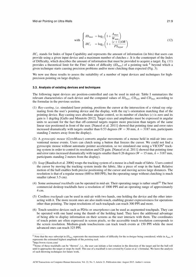
3.3. Analysis of existing devices and techniques
The following input devices are position-controlled and can be used in mid-air. Table I summarizes therelevant characteristics of each device and the computed values of IDmax, CDmin and CDmax according tothe formulae in the previous section.
(1) Ray-casting, i.e. simulated laser pointing, positions the cursor at the intersection of a virtual ray orig-inating from the user’s pointing device and the display, with the ray’s orientation matching that of thepointing device. Ray-casting uses absolute angular control, so its number of clutches (c) is zero and itsgain is 1 deg/deg [Gallo and Minutolo 2012]. Target sizes and amplitudes must be expressed in angularunits to account for the fact that off-centered targets require more precision than targets of the samelinear size positioned in front of the user. [Nancel et al. 2011] showed that pointing time and error ratesincreased dramatically with targets smaller than 0.53 degrees (W = 30 mm, A = 3187 mm, participantsstanding 2 meters away from the display).
(2) A gyroscopic mouse (GyroMouse) converts angular movements of a mouse held in mid-air into con-ventional mouse events. Users can clutch using a button that freezes the cursor. We could not find agyroscopic mouse without automatic pointer acceleration, so we simulated one using a VICON9 track-ing system in order to control its resolution and CD gain. [Nancel et al. 2011] showed that pointing timeand error rates increased dramatically with targets smaller than 0.26 degrees (W = 15 mm, A= 3187 mm,participants standing 2 meters from the display).
(3) Soap [Baudisch et al. 2006] wraps the tracking system of a mouse in a hull made of fabric. Users controlthe cursor by moving the tracking system inside the fabric, like a piece of soap in the hand. Relativemotion of the hull enables both precise positioning of the cursor and moving across large distances. Theresolution is that of a regular mouse (600 to 800 PPI), but the operating range without clutching is muchsmaller (about 3.5 cm).
(4) Some unimanual trackballs can be operated in mid-air. Their operating range is rather small10 The bestcommercial desktop trackballs have a resolution of 1000 PPI and an operating range of approximately4 cm.
(5) Cordless trackpads can be used in mid-air with two hands, one holding the device and the other inter-acting with it. The more recent ones are also multi-touch, enabling greater expressiveness for operationsother than pointing. The input resolutions of such trackpads can reach 300 PPI and more.
(6) Touch-sensitive devices such as PDAs or smartphones can be used as augmented touchpads. They canbe operated with one hand using the thumb of the holding hand. They have the additional advantageof being able to display information on their screens as the user interacts with them. The coordinatesof touch points are often expressed in screen pixels, so the accessible touch resolution corresponds tothe screen resolution. Medium-grade touchscreens can track touch events at 150 PPI while the mostadvanced ones can reach 325 PPI.
8 Note that the max subscript in IDmax represents the maximum index of difficulty for the technique being considered, while in Amax itrepresents the estimated highest amplitude of the pointing task.9http://www.vicon.com/10Some of these trackballs can be “thrown”, i.e., the user can initiate a fast rotation in the direction of the target and let the ball rolluntil it approaches the target or stops by itself. This use of a trackball is not covered by Casiez et al.’s formulae. We leave the analysisof such throwing techniques for future work.
ACM Transactions on Computer-Human Interaction, Vol. 22, No. 5, Article 21, Publication date: August 2015. Author’s version

Mid-air Pointing on Ultra-Walls 21:10
(7) Tablets also provide visual feedback with greater input surfaces than touchpads and smartphones, butmust be used with two hands. Their touch resolution is between 100 PPI and more than 250 PPI.
c = 0Device Hands PSdevice OR Reshand IDmax CDmin CDmax Min cSoap 1 32 µm (800 PPI) 35 mm 0.2 mm 7.46 91.1 20 4
Trackball 1 32 µm (800 PPI) 40 mm 0.2 mm 7.65 79.7 20 3GyroMouse 1 15.5 mdeg (65 PPD)11 90 deg 0.26 deg 8.42 35.4 mm
deg 15.2 mmdeg 2
RayCasting 1 15.5 mdeg 77 deg 0.53 deg 7.21 1 0.13 N/ASmartphonem 1 156 µm (163 PPI) 75 mm 0.2 mm 8.55 42.5 20 2Smartphonet 1 78 µm (325 PPI) 89 mm 0.2 mm 8.8 35.9 20 1
Trackpad 2 66 µm (387 PPI) 105 mm 0.2 mm 9.04 30.4 20 1Tabletm 2 192 µm (132 PPI) 197 mm 0.2 mm 9.94 16.2 20 0Tablett 2 96 µm (264 PPI) 197 mm 0.2 mm 9.95 16.2 20 0
Amax = 3187 mm, Wmin = 4 mm
Table I: Device characteristics for pointing techniques. Entries in red have CDmin > CDmax and are therefore im-practical. Min c represents the minimum number of clutches that would be necessary to ensure that CDmin < CDmax.Subscripts m and t indicate medium-grade and top-grade devices. We used the larger dimension for touch devices.
In order to compute CDmin and CDmax for each of the above devices, we must define their operating range(OR) and their hand and device resolutions (Reshand and PSdevice). For the Trackpad, Trackball, Smart-phones, Tablets and Soap, we used Casiez et al.’s conservative estimate for Reshand (0.2 mm) while forGyroMouse we adapted the formulae to obtain CD gains expressed in mm/deg. We used the smallest targetsize evaluated in Subsection 3.1 (Wmin = 4 mm) and maximum amplitude Amax = 3187 mm), resulting in amaximum Fitts’ index of difficulty of 9.64 bits.
Table I summarizes the CD gain computations for the selected devices. All but the tablets have a CDminlarger than their CDmax. They are therefore very likely to create clutching and/or precision problems ifused with constant CD gains. This is also indicated by their IDmax, which is smaller than the maximumFitts’ index of difficulty of the task, and by their minimum number of clutches Min c. We confirmed thisassessment by informally evaluating various handheld trackballs, trackpads, smartphones and tablets.
This analysis shows that with the exception of tablets, which must be operated with two hands, fixed CDgains make it difficult at best to perform the more challenging yet realistic mid-air pointing tasks thatultra-walls may require. The users’ motor capabilities and the devices’ sensing capabilities are too limitedto acquire targets that users can visually perceive with normal visual acuity, at least with constant gains.The use of clutching can improve the situation but at the cost of greater movement times, and only forrelative techniques. This confirms that ultra-walls are a limit case in Jellinek et al.’s hypothesis [Jellinek andCard 1990]: pointing techniques with varying gains become necessary beyond a certain level of pointingdifficulty, because the precision required to acquire very small targets leads to high upper bounds on thesize of the ‘device footprint’ (OR in the equations above).
This problem is best described by Eq. 10-12: for a given user, device and acceptable number of clutches,there is a maximum pointing difficulty IDmax beyond which a constant CD gain becomes inefficient. Harderpointing tasks, i.e. with higher amplitudes or smaller targets, require techniques that vary their gain, allowingfaster movement for distant targets and more precise movements for small targets. In the next section wedescribe and analyze two families of techniques that provide controllable ranges of CD gains.
4. THEORETICAL MODELS FOR DIFFICULT MID-AIR POINTING TASKS
We established in section 3.1 that we needed to be able to point at targets as small as 4mm from a distanceon a 5 meter wide ultra-wall, resulting in an index of difficulty of about 9.3 bits for an amplitude of twothirds of the width of the display. In the remainder of this paper, we call pointing tasks with an ID larger than9 bits “difficult pointing tasks”. We showed in Section 3.3 that apart from tablets, which must be operatedwith two hands, current input devices cannot reach this level of difficulty using a constant CD gain withoutclutching. We now explore techniques with varying CD gains.
The literature describes two main ways to increase the range of CD gains of target-agnostic pointing tech-niques:
11mdeg stands for millidegrees, PPD for Points Per Degrees. The values were computed using a 10-camera VICON system.
ACM Transactions on Computer-Human Interaction, Vol. 22, No. 5, Article 21, Publication date: August 2015. Author’s version

Mid-air Pointing on Ultra-Walls 21:11
— Pointer Acceleration functions (‘hydromatic-glide’ in [Jellinek and Card 1990]) dynamically adjust theCD gain according to the velocity of the user’s movements, based on the principle that the faster the inputmovement, the further away the cursor should go. Most operating systems use Pointer Acceleration,both for trackpads and mice. [Casiez and Roussel 2011] reverse-engineered the corresponding transferfunctions so that HCI researchers can simulate them accurately. However, there is very little literatureabout how to design such functions, especially for highly demanding platforms such as ultra-walls.
— Dual-Precision techniques provide two pointing modes: a Coarse mode to cover large distances withfast movements, and a Precise mode to acquire small targets at a short distance. Mode switching istriggered by a user action such as depressing a button [Kopper et al. 2010], changing the hand posture[Vogel and Balakrishnan 2005], or tapping vs dragging on a touch surface [McCallum and Irani 2009].Coarse modes are usually implemented with absolute control and Precise modes with relative control.This is similar to the ‘manual powermouse’ described in [Jellinek and Card 1990].
The main difference between these two approaches is the transition between low and high CD gains. PointerAcceleration features a continuous, implicit transition based on input movement properties, while Dual-Precision techniques use a discrete mode switch that is explicitly triggered by the user. [Gallo and Minutolo2012] introduced a hybrid approach that uses two pointing modes, one absolute and one relative, with animplicit, gradual transition based on input velocity similar to the ‘automatic powermouse’ [Jellinek andCard 1990]). They describe a detailed method to calibrate the corresponding transfer function, but we willshow that this function does not meet the constraints of ultra-walls.
We are also interested in pointing techniques that use minimal input resources, so that users can hold otherinput devices or use the one used for pointing for other purposes. We explored two approaches: unimanualtechniques that let users hold other, non-pointing devices in their non-dominant hand if necessary, and touch-based techniques that use a small portion of the touch screen to keep more space for additional widgets.
We first introduce a formal definition and a framework for Dual-Precision techniques and use the formulaefrom the previous section to define a calibration method for their CD gains and feedback. Then we describea new transfer function for Pointer Acceleration and describe a simple method to calibrate it. Note that weuse the classic formulation of Fitts’ law as well as Cartesian coordinates, even though we later apply themethod to angular-based techniques for which the models in [Kopper et al. 2010] and [Jota et al. 2010]might provide a better fit. Our goal is to devise general methods that let us compare results directly, witha common definition of task difficulty. Refining these methods for specific types of input is left for futurework.
4.1. Dual-Precision pointing techniques
The first phase of a pointing task, especially with large amplitude, is a ballistic phase [Meyer et al. 1988] inwhich users control the direction and velocity of the cursor but only have limited control over its location.The second phase of a pointing task consists of bringing the cursor within the target and may require highprecision when the target is small, thus a finer control over the cursor location and a lower velocity. Thesetwo phases require users to focus on two different trade-offs between speed and precision, and the transitionbetween them can be challenging with difficult pointing tasks.
A pointing technique should adapt to the hardware and performance requirements of a task. In particular,it should provide fast cursor movements for large amplitudes and precise control for small targets12. Whilethese two aspects are well covered in the literature about pointing techniques in desktop environments,the analysis of the previous section and the results presented in [Nancel et al. 2011] show that existingtechniques hit a performance ceiling with high Fitts’ IDs such as those required on ultra-walls.
Based on existing designs [Forlines et al. 2006; McCallum and Irani 2009; Vogel and Balakrishnan 2005],we formally define Dual-Precision pointing techniques as techniques that explicitly divide pointing tasksinto two phases of different velocities:
— a coarse phase in which users quickly approach the target by traversing most of the task amplitude withno or minimal clutching,
— a precise phase in which they can acquire nearby targets as small as the smallest visible size.
Dual-precision pointing techniques therefore feature two modes, Coarse and Precise, with explicit modeswitches.
12Other aspects can be considered, such as how a given technique allows accurate steering. Here we only consider pointing difficultyas modeled by Fitts’ ID.
ACM Transactions on Computer-Human Interaction, Vol. 22, No. 5, Article 21, Publication date: August 2015. Author’s version

Mid-air Pointing on Ultra-Walls 21:12
A
Cursor(Ø=L)
Target
d ≤ L/2
Mode switch
(c)(b) (d)(a)
Fig. 4: A Dual-Precision technique: In Coarse mode the cursor features a circle indicating the range of the precisemode L (a). The user brings the area cursor over the target (b), i.e. at a distance d ≤ L
2 , then switches to Precisemode (c). She finishes the task in Precise mode (d).
Coarse and Precise modes can each be absolute or relative. Absolute controls are clutch-less and straightfor-ward to use because the previous cursor location does not impact the input movement, i.e. the cursor can beteleported; however they have fixed gains and thus limited precision (see Section 3.2). Pointer Accelerationtransfer functions and broader ranges of CD gains can be applied to relative controls, but an offset betweenthe input and cursor locations is likely to build up, leading to clutch actions. Most Dual-Precision techniquesin the literature use absolute control for Coarse pointing and relative control for Precise pointing.
Note that any technique featuring more than one precision mode, such as Smoothed Pointing [Gallo andMinutolo 2012], could be categorized as having double or multiple precision. However, consistent with pre-vious work [Nancel et al. 2013; Nancel et al. 2011], we define Dual-Precision pointing techniques as havingan explicit mode switch (Smoothed Pointing’s is implicit) and supporting the precision of the smallest tar-gets of a given application.
4.1.1. Theoretical analysis of dual-precision techniques. The design of Dual-Precision techniques relieson four key parameters: the transfer functions used in each phase, the point at which the user is expected toswitch modes and the mode switch mechanism.
In order to be optimal, the mode switch should occur when the target is within range of the Precise mode,a distance we denote L. Switching mode outside this range causes either clutching or switching back toCoarse mode to bring the cursor closer to the target before switching again. With practice, users can learnthis distance [McCallum and Irani 2009]. However we propose to visually represent this limited operatingrange by surrounding the cursor with a circle of diameter L when in Coarse pointing mode (Fig. 4-a) to helpnovice users familiarize with this distance. The coarse pointing phase can then be seen as an area cursorpointing task [Kabbash and Buxton 1995] that consists in bringing the cursor’s circle over the target (Fig. 4-b), while the precise pointing phase is a regular target acquisition task with a distance d lower or equal toL/2 (Fig. 4-c,d).
Dual-Precision pointing techniques separate difficult pointing tasks into two pointing actions of lower dif-ficulties. As mentioned before, Fitts’ law is expressed as a linear model of an Index of Difficulty (Fitts’ ID)computed from the task width (W ) and amplitude (A):
MT = a+b× log2(1+A/W ) (13)
In our case, the Coarse phase corresponds to bringing the cursor close enough to the target in order to beable to use the Precise mode. The corresponding index of difficulty is
IDC = log2(1+A/L)
Similarly, the Precise phase consists in bringing the cursor from the location of the mode switch to thetarget, thus moving a distance d supposedly lower or equal than L/2. The corresponding index of difficultyis
IDP = log2(1+d/W) (14)
We cannot predict the value of d, so we use L/2 as a higher bound to compute the Fitts’ ID of the Precisephase:
IDP = log2(1+L/2W) (15)
ACM Transactions on Computer-Human Interaction, Vol. 22, No. 5, Article 21, Publication date: August 2015. Author’s version
Mid-air Pointing on Ultra-Walls 21:13
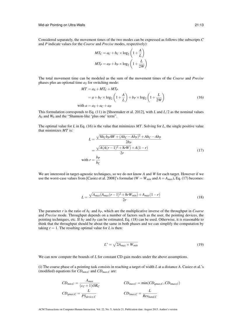
Considered separately, the movement times of the two modes can be expressed as follows (the subscripts Cand P indicate values for the Coarse and Precise modes, respectively):
MTC = aC +bC× log2
(1+
AL
)MTP = aP +bP× log2
(1+
L2W
)
The total movement time can be modeled as the sum of the movement times of the Coarse and Precisephases plus an optional time aS for switching mode:
MT = aS +MTC +MTP
= a+bC× log2
(1+
AL
)+bP× log2
(1+
L2W
)(16)
with a = aS +aC +aP
This formulation corresponds to Eq. (11) in [Shoemaker et al. 2012], with L and L/2 as the nominal valuesA0 and W0 and the “Shannon-like ‘plus one’ term”.
The optimal value for L in Eq. (16) is the value that minimizes MT . Solving for L, the single positive valuethat minimizes MT is:
L =
√8bCbPAW +(AbC−AbP)2 +AbC−AbP
2bP
=
√A(A(r−1)2 +8rW )+A(1− r)
2r(17)
with r =bP
bC
We are interested in target-agnostic techniques, so we do not know A and W for each target. However if weuse the worst-case values from [Casiez et al. 2008]’s formulae (W =Wmin and A = Amax), Eq. (17) becomes:
L =
√Amax(Amax(r−1)2 +8rWmin)+Amax(1− r)
2r(18)
The parameter r is the ratio of bC and bP, which are the multiplicative inverse of the throughput in Coarseand Precise mode. Throughput depends on a number of factors such as the user, the pointing devices, thepointing techniques, etc. If bC and bP can be estimated, Eq. (18) can be used. Otherwise, it is reasonable tothink that the throughput should be about the same in both phases and we can simplify the computation bytaking r = 1. The resulting optimal value for L is then:
L∗ =√
2Amax×Wmin (19)
We can now compute the bounds of L for constant CD-gain modes under the above assumptions.
(i) The coarse phase of a pointing task consists in reaching a target of width L at a distance A. Casiez et al.’s(modified) equations for CDmin,C and CDmax,C are:
CDmin,C =Amax
(cC +1)ORCCDmax,C = min(CDqmax,C,CDlmax,C)
CDqmax,C =L
PSdevice,CCDlmax,C =
LReshand,C
ACM Transactions on Computer-Human Interaction, Vol. 22, No. 5, Article 21, Publication date: August 2015. Author’s version
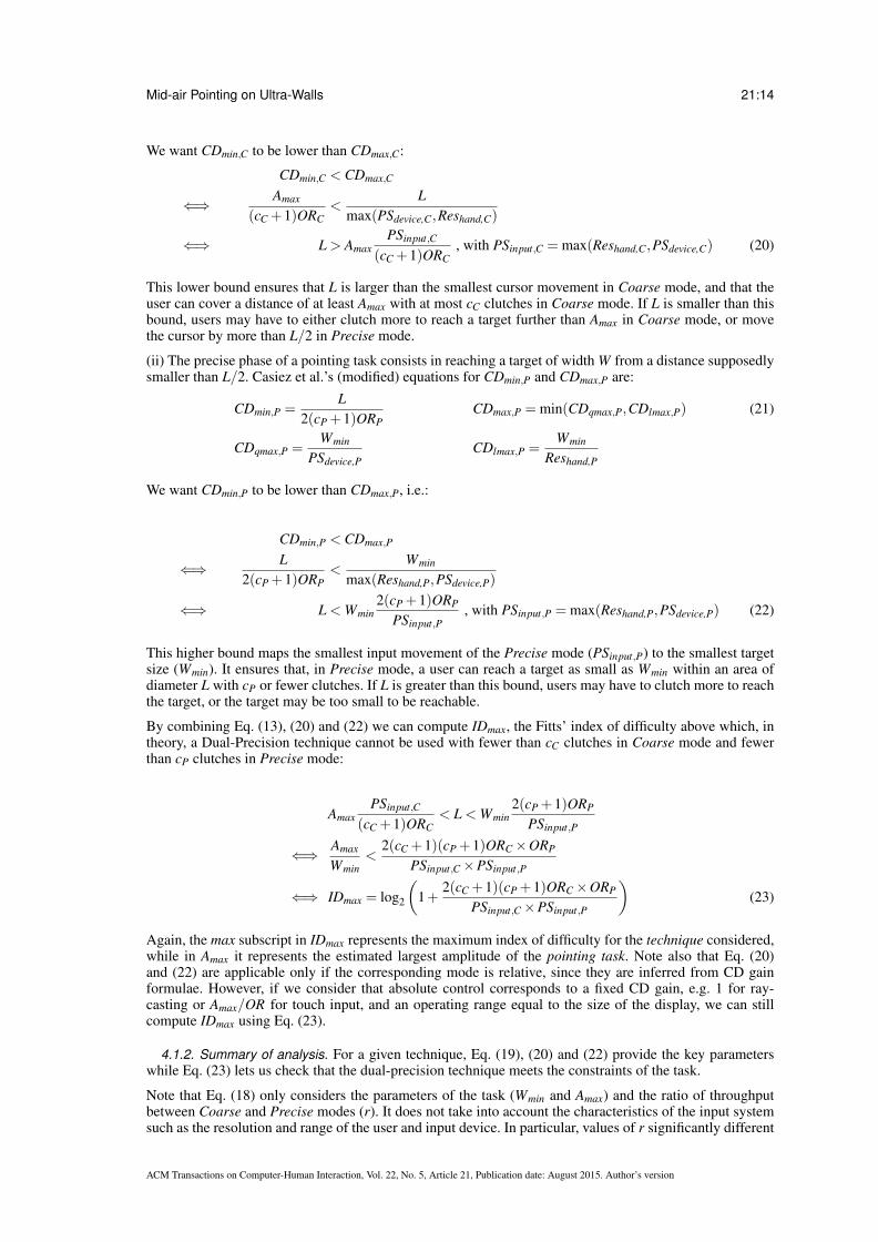
Mid-air Pointing on Ultra-Walls 21:14
We want CDmin,C to be lower than CDmax,C:
CDmin,C < CDmax,C
⇐⇒ Amax
(cC +1)ORC<
Lmax(PSdevice,C,Reshand,C)
⇐⇒ L > AmaxPSinput,C
(cC +1)ORC, with PSinput,C = max(Reshand,C,PSdevice,C) (20)
This lower bound ensures that L is larger than the smallest cursor movement in Coarse mode, and that theuser can cover a distance of at least Amax with at most cC clutches in Coarse mode. If L is smaller than thisbound, users may have to either clutch more to reach a target further than Amax in Coarse mode, or movethe cursor by more than L/2 in Precise mode.
(ii) The precise phase of a pointing task consists in reaching a target of width W from a distance supposedlysmaller than L/2. Casiez et al.’s (modified) equations for CDmin,P and CDmax,P are:
CDmin,P =L
2(cP +1)ORPCDmax,P = min(CDqmax,P,CDlmax,P) (21)
CDqmax,P =Wmin
PSdevice,PCDlmax,P =
Wmin
Reshand,P
We want CDmin,P to be lower than CDmax,P, i.e.:
CDmin,P < CDmax,P
⇐⇒ L2(cP +1)ORP
<Wmin
max(Reshand,P,PSdevice,P)
⇐⇒ L < Wmin2(cP +1)ORP
PSinput,P, with PSinput,P = max(Reshand,P,PSdevice,P) (22)
This higher bound maps the smallest input movement of the Precise mode (PSinput,P) to the smallest targetsize (Wmin). It ensures that, in Precise mode, a user can reach a target as small as Wmin within an area ofdiameter L with cP or fewer clutches. If L is greater than this bound, users may have to clutch more to reachthe target, or the target may be too small to be reachable.
By combining Eq. (13), (20) and (22) we can compute IDmax, the Fitts’ index of difficulty above which, intheory, a Dual-Precision technique cannot be used with fewer than cC clutches in Coarse mode and fewerthan cP clutches in Precise mode:
AmaxPSinput,C
(cC +1)ORC< L < Wmin
2(cP +1)ORP
PSinput,P
⇐⇒ Amax
Wmin<
2(cC +1)(cP +1)ORC×ORP
PSinput,C×PSinput,P
⇐⇒ IDmax = log2
(1+
2(cC +1)(cP +1)ORC×ORP
PSinput,C×PSinput,P
)(23)
Again, the max subscript in IDmax represents the maximum index of difficulty for the technique considered,while in Amax it represents the estimated largest amplitude of the pointing task. Note also that Eq. (20)and (22) are applicable only if the corresponding mode is relative, since they are inferred from CD gainformulae. However, if we consider that absolute control corresponds to a fixed CD gain, e.g. 1 for ray-casting or Amax/OR for touch input, and an operating range equal to the size of the display, we can stillcompute IDmax using Eq. (23).
4.1.2. Summary of analysis. For a given technique, Eq. (19), (20) and (22) provide the key parameterswhile Eq. (23) lets us check that the dual-precision technique meets the constraints of the task.
Note that Eq. (18) only considers the parameters of the task (Wmin and Amax) and the ratio of throughputbetween Coarse and Precise modes (r). It does not take into account the characteristics of the input systemsuch as the resolution and range of the user and input device. In particular, values of r significantly different
ACM Transactions on Computer-Human Interaction, Vol. 22, No. 5, Article 21, Publication date: August 2015. Author’s version

Mid-air Pointing on Ultra-Walls 21:15
from 1 may lead to unrealistic values for L. In such cases, Eq. (20) and (22) provide bounds for the valueof L that ensure that the technique’s expected Precise amplitude remains realistic. Note also that Eq. (20),(22) and (23) were based on [Casiez et al. 2008]’s formulae for constant-CD gain techniques and thereforeapply primarily to pointing modes using a constant gain.
4.2. Control-Display Transfer Functions
We now turn to the study of variable-gain transfer functions that can work for ultra-walls. Pointer Accel-eration consists in applying a transfer function to the Control-Display gain based on the dynamics of theusers’ movements. As mentioned earlier, optimizing the transfer function that controls Pointer Accelerationfor ultra-walls is challenging and previous literature on position-based pointing is scarce13.
The transfer functions used in major desktop operating systems [Casiez and Roussel 2011] work for single-and multi-monitor display configurations but are not adapted to ultra-walls, which typically have a 200to 400 inches diagonal and a resolution of, e.g., 20 480× 6 400 for our evaluation platform (Fig. 1).Beyond recent work by Casiez et al. that provides a general framework but does not address such con-texts [Casiez and Roussel 2011; Casiez et al. 2008], the only documented calibration methods are those re-lated to PRISM [Frees et al. 2007] and its refinements [Konig et al. 2009; Gallo and Minutolo 2012]. Thesemethods, however, were designed to calibrate absolute-to-relative transfer functions for pointing techniquesthat feature an implicit mode switch between absolute and relative pointing. While we later compare ourtechniques with those, this work is of little use to calibrate purely relative transfer functions. Finally, theone-dimensional transfer function described in [Cockburn et al. 2012] that adapts to the maximum taskamplitude was designed for scrolling long documents but was never evaluated with pointing tasks.
In our context, Pointer Acceleration must be adapted to enable relocation of the cursor across the display(corresponding to amplitudes of 5 meters and more) at high input speeds with minimal clutching. Thisrequires a high CD gain. Conversely, CD gain must be set to a low value at low input speeds so as to enablehigh-precision cursor control.
We use sigmoid transfer functions similar to those used for rate-based pointing [Rutledge and Selker 1990]and in some operating systems [Casiez et al. 2008; Casiez and Roussel 2011]. They are characterized bya slope that smoothly gets steeper before flattening again, as illustrated in Fig. 5. The flatter slope at theleft end enables higher precision at low input velocities. The flatter slope at the right end limits maximumcursor speed.
0.0 0.1 0.2 0.3 0.4 0.5
01
02
03
04
0
Velocity (m/s)
CD
ga
in
l
Vmin
VmaxVinf
CDmax
CDmin
Fig. 5: An example of logistic sigmoid curve (used in condition RelaLarge of the experiment reported in Section 7). Inthis example Vmin= 6 mm/s, Vmax= 37 cm/s, CDmin = 0.22, CDmax = 43.1, λ = 0.02 s/mm and ratioin f= 0.5.
To model such curves, we use a simple form of the generalized logistic function:
CD(x) =CDmax−CDmin
1+ e−λ (x−Vin f )+CDmin (24)
where Vin f = ratioin f .(Vmax−Vmin)+Vmin.
This function can be tuned with six parameters:
13A recent study from [Roussel et al. 2012] partially addresses this issue, but was published after the work described here was con-ducted.
ACM Transactions on Computer-Human Interaction, Vol. 22, No. 5, Article 21, Publication date: August 2015. Author’s version

Mid-air Pointing on Ultra-Walls 21:16
010
2030
40
Velocity (m/s)
CDgain
0.40.30.20.10 0.5
CDmax
CDmin
Vmin Vmax
Fig. 6: Examples of curves with the same values for Vmin, Vmax, ratioin f , CDmin and CDmax, and a varying λ . The red,blue and green curves correspond to decreasing values of λ . The values of the function at the ends of the input velocityrange (small circles) illustrate the fact that lower values of λ reduce the effective output range relatively to the expectedoutput range [CDmin−CDmax].
— Vmin and Vmax are estimates of the lower and upper bounds of input velocity beyond which accuratecontrol becomes difficult. The input function is not constrained to this velocity range: some very fast orvery precise movements may exceed these bounds.
— ratioin f controls the position of the inflexion point within this range: 0 sets the inflexion point at Vmin, 1sets it at Vmax and 0.5 sets it in between. We use a ratio rather than an absolute value because it is thenindependent from the velocity range. Vin f is the velocity at the inflextion point.
— CDmax and CDmin are asymptotic values that bound the output range of the function. They depend onthe task (Amax and Wmin) and can be adjusted according to users’ motor capabilities.
— λ is related to the slope of the curve at its inflexion point, defined as:
CD′(Vin f ) =λ × (CDmax−CDmin)
4(25)
λ = 0 yields a constant function, λ =+∞ a step function. λ is expressed in seconds per input units.
λ is a trade-off between the smoothness of the curve and how close to CDmin and CDmax the resultingtransfer function can go for input velocities in the [Vmin;Vmax] range. Low values (Fig. 6, green) make forsmoother curves but CDmin and CDmax are harder to reach. High values (Fig. 6, red) increase the effectiveoutput range of the function but make it steeper, and thus possibly harder to control around the inflexionpoint.
We designed the following procedure to calibrate these parameters:
(1) Vmin and Vmax are set respectively to the 90th percentile and the median of two corpora of velocitiescorresponding to voluntarily slow and fast movements collected using the input device14;
(2) CDmin is set to the ratio of the minimum target size to the smallest input movement amplitude (mininput )that is considered usable for selecting a target15: CDmin =
Wminmininput
.The initial value for CDmax is set to the ratio of the maximum pointing amplitude to the correspondingdimension of the dedicated input zone, scaled by the maximum number of pointing movements (c+1)where c is the acceptable number of clutches. Maximum amplitude is Amax for mode-less techniques andCoarse modes, or L for Precise modes. The dimension of the dedicated input zone diminput is its widthfor a horizontal movement or its height for a vertical movement, provided that the input zone has thesame aspect-ratio than the display.
CDmax =Amax or L
(c+1)diminput
In the most constrained cases where the curve remains too steep for accurate control after steps 3 and4, the output CD-gain range must be reduced. Increasing CDmin makes smaller targets much harder toselect and potentially unreachable. Reducing CDmax increases the number of clutches, but effectively
14Note that previous work such as [Aceituno et al. 2013] investigate the limits to human motor control, while this step defines acomfortable control range.15Note that this method enables subpixel pointing [Roussel et al. 2012] by setting Wmin to less than the size of one pixel.
ACM Transactions on Computer-Human Interaction, Vol. 22, No. 5, Article 21, Publication date: August 2015. Author’s version

Mid-air Pointing on Ultra-Walls 21:17
reduces the output range of the function. This makes it easier to smoothen the curve (see step 4) butlowers the cursor’s maximum velocity.
(3) ratioin f defines the relative position of the inflexion point. As described earlier, fast input motionsindicate the user’s intention to move the cursor over a long distance while slow input motions indicatethe user’s intention to perform short-range, precise movements. ratioin f defines the location of thetransition between these two behaviors within the input velocity range. ratioin f should initially be set to.5 then adjusted if a different setting improves the trade-off between the two types of control:
010
2030
40
Velocity (m/s)
CDgain
Vmin
Vmax
Vinf
0.40.30.20.10 0.5
Smaller values make the cursor accelerate early, i.e. a large section ofthe input velocity range (right part, in blue) is dedicated to fast cursormovements, making them more controllable than precise ones; usersmust therefore be able to finely control their slowest input movements(red section) to select small targets.
010
2030
40
Velocity (m/s)
CDgain
Vmin
Vmax
Vinf
0.40.30.20.10 0.5
Larger values make the cursor accelerate later, i.e. a larger section ofthe input velocity range (left part, in blue) is dedicated to precise cur-sor movements, making them more controllable than fast ones; usersmust therefore be able to perform movements fast enough (red) to travelthrough large amplitudes.
Note that ratioin f can be negative or greater than 1 if the chosen input range [Vmin; Vmax] does not accu-rately describe the effective velocity range that the users can cover.
(4) λ is directly proportional to the curve’s maximum steepness (Eq. (25), Fig. 6). In order to avoid steepchanges in velocity, λ should be set to the smallest value while still covering a sufficient part of theCD-gain output range to perform the most difficult pointing tasks with minimum clutching. A conser-vative initial value for λ is computed from the slope of the line that goes through (Vmin,CDmin) and(Vmax,CDmax), i.e. λ0 = 4
Vmax-Vmin. This value ensures that 76 % of the output range [CDmin,CDmax] is
reachable from the input range [Vmin,Vmax] with minimal steepness. It proved to be a safe lower bound tocalibrate the techniques presented later in this paper.
Step 1 in the above procedure results in indicative values for Vmin and Vmax that serve as a starting point forthe calibration of the other parameters. Vmin and Vmax should not be changed after step 1: although Vin f isinitially defined within this input range, it is used in Eq. 24 as an absolute value, so Vmin and Vmax do notactually affect the transfer function once a suitable ratioin f is chosen.
1
[Vmin, Vmax]
2
[CDmin, CDmax]
3
ratioinf
4
λ(a)
(b)(c)
Fig. 7: State machine diagram of the calibration process described above. States correspond to the steps of the calibra-tion process. Step 1 is the initial state, steps 3 and 4 are the two potential final states. Transition (c) occurs when nomodification of the couple {ratioin f , lambda} provides a satisfying pointing behavior.
A typical calibration process (Fig. 7) consists of performing steps 1 to 4, possibly cycling between steps 3and 4 until a satisfying behavior is found. If no satisfying values can be found for ratioin f and λ , the outputrange can be relaxed (transition (c) in Fig 7), e.g. by allowing more clutches or by increasing the minimaltarget width if the initial Wmin was loo low. The tuning process is considered over when (1) users can performthe most difficult task (largest amplitude, smallest target width) and (2) no further parameter tweaking canimprove pointing performance or the users’ subjective perception of smoothness and precision.
ACM Transactions on Computer-Human Interaction, Vol. 22, No. 5, Article 21, Publication date: August 2015. Author’s version
Mid-air Pointing on Ultra-Walls 21:18
This procedure is the result of an extensive iterative design process. We used it successfully to calibrateall the pointing (non-constant) transfer functions for the techniques evaluated in this paper. It was alsoused successfully for pointing with a device combining elecromyographic and inertial sensors [Haque et al.2015]. The Smarties toolkit [Chapuis et al. 2014] also uses this transfer function for pointing on wall-display with touch devices, allowing developers to fine tune its parameters. However we leave the formalcomparison of this procedure with other calibration methods to future work.
4.3. Validating our theoretical analyses
We presented the two main strategies used in the literature to augment the range of available Control-Displaygains for difficult pointing tasks: dual-precision techniques that switch explicitly between a Coarse and aPrecise mode, and Pointer Acceleration transfer functions that adapt the CD gain to the velocity of the inputmovement. Note that these two approaches are not mutually exclusive: a dual-precision technique couldfeature Pointer Acceleration functions in its modes. We also presented formulae and methods to calibratethe CD gains of pointing techniques that use these strategies.
The next three sections report on the design and evaluation of pointing techniques that were calibrated withthese methods. Considering the large design space for pointing techniques in mid-air, we chose to organizeour experimental work according to external interaction constraints, i.e. which other input channel andinteraction techniques could be required in a real-world use of our techniques: (i) pointing techniques thatrequire only one hand, leaving the non-dominant hand free for other purposes such as holding a secondarydevice or inputting gestures; and (ii) dual-precision pointing techniques that require only small areas ofa touch-enabled surface, leaving as much of the interactive surface as possible free for other touch-basedinteractions. The third experiment compares Pointer Acceleration-only techniques that use a small area of atouch-enabled surface with the best techniques of the previous experiments and of the literature.
5. STUDY 1: SINGLE- VS. DUAL-PRECISION UNIMANUAL TECHNIQUES
In this first experiment, we focus on techniques that can be operated with a single hand (the dominant one),in order to allow the other hand to hold and control other input devices. Following the two families oftechniques introduced in the previous section, we designed a Pointer Acceleration technique and exploredthree Dual-Precision pointing techniques.
5.1. Techniques
GyroAcc is a single-mode Pointer Acceleration technique that applies a custom-made transfer function tothe rotation of a hand-held wireless mouse to control cursor translation: yaw is mapped to horizontal cursormovements and pitch to vertical cursor movements. The transfer function, detailed later, was calibratedusing the procedure described in Section 4.2. The user can click with the left button of the wireless mouseand freeze the cursor with the right button to adjust the offset between cursor position and limb orientation,also known as clutching.
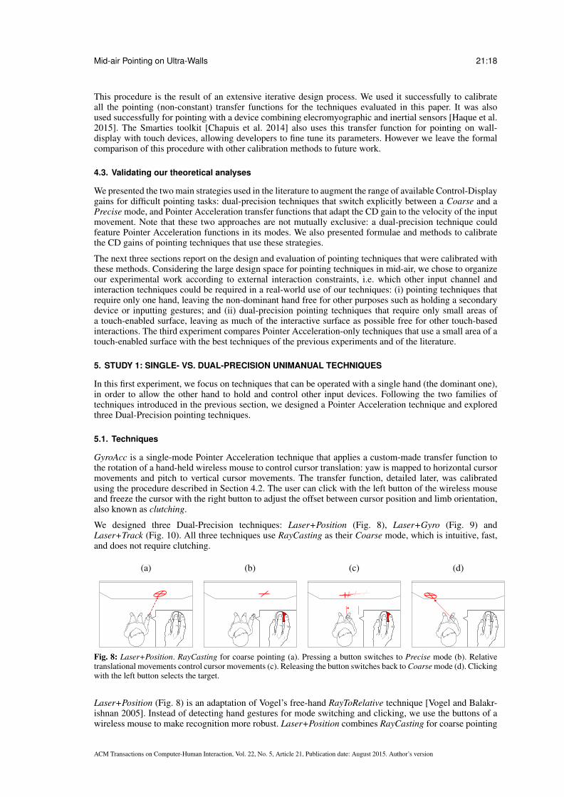
We designed three Dual-Precision techniques: Laser+Position (Fig. 8), Laser+Gyro (Fig. 9) andLaser+Track (Fig. 10). All three techniques use RayCasting as their Coarse mode, which is intuitive, fast,and does not require clutching.
(a) (b) (c) (d)
Fig. 8: Laser+Position. RayCasting for coarse pointing (a). Pressing a button switches to Precise mode (b). Relativetranslational movements control cursor movements (c). Releasing the button switches back to Coarse mode (d). Clickingwith the left button selects the target.
Laser+Position (Fig. 8) is an adaptation of Vogel’s free-hand RayToRelative technique [Vogel and Balakr-ishnan 2005]. Instead of detecting hand gestures for mode switching and clicking, we use the buttons of awireless mouse to make recognition more robust. Laser+Position combines RayCasting for coarse pointing
ACM Transactions on Computer-Human Interaction, Vol. 22, No. 5, Article 21, Publication date: August 2015. Author’s version

Mid-air Pointing on Ultra-Walls 21:19
and relative translational movements of the hand/device for precise pointing. In Precise mode, the hand’stranslation is taken into account in a plane orthogonal to the orientation of the hand-held device whenswitching mode (Fig. 8-b). Precise pointing is activated by keeping a button depressed. A second button isused for clicking. Users can clutch in Precise mode by releasing the first button and repositioning their handquickly: If they press the first button again within less than 600 ms (tuned through pilot testing), the tech-nique doesn’t switch back to Coarse mode while the button is up. Informal testing showed that an operatingrange of 300 mm for the Precise mode was large enough without causing too much fatigue. The theoreticallimit of difficulty (Eq. (23)) for Laser+Position is approximately 18.2 bits, i.e., much higher than neededfor a task that does not involve zooming or lenses (A/W ≈ 300,000).
(a) (b) (c) (d)
Fig. 9: Laser+Gyro. RayCasting for coarse pointing (a). Pressing a button switches to Precise mode (b). Relativerotational movements control cursor movements (c). Releasing the button switches back to Coarse mode (d). Clickingwith the left button selects the target.
Laser+Gyro (Fig. 9) combines RayCasting for coarse pointing and relative rotational movements for pre-cise pointing. This is somewhat similar to the ARM technique [Kopper et al. 2008; Kopper et al. 2010].However, the ‘precision mode’ of ARM is perspective-dependent, since the lower gain is applied to the rel-ative movement of the point at the intersection of the ray and the display surface (as in Smoothed Pointing[Gallo and Minutolo 2012]). In addition, ARM requires both hands. Compared to Laser+Position, whichmainly involves upper limb segments (forearm to shoulder) in Precise mode, Laser+Gyro mainly involvesthe wrist and/or elbow and is potentially less tiring. Clutching, clicking and mode switching are identi-cal to the Laser+Position technique. Our tests showed that an operating range of π rad was large enoughfor the Precise mode while not causing too much fatigue. The theoretical limit of difficulty (Eq. (23)) forLaser+Gyro is approximately 19 bits.
(a) (b) (c) (d)
Fig. 10: Laser+Track. RayCasting for coarse pointing (a). Touching the surface switches to Precise mode (b). Movingthe thumb over the surface controls cursor movements (c). Lifting the thumb switches back to Coarse mode (d). Tappingthe bottom part of the screen selects the target (Fig.11).
Laser+Track (Fig. 10) combines RayCasting for coarse pointing and relative translational movements of thethumb on a touch-sensitive surface (PDA, smartphone, etc.) for precise pointing. The surface is divided intotwo zones (Fig. 11): an upper zone (1) for tracking and a lower (smaller) zone (2) for clicking. Switchingbetween the two zones can be achieved easily using proprioceptive information and, after a short learningphase, does not require the user to look at the device. Touching the upper zone switches to Precise mode.Switching back to Coarse mode only happens 300 ms (tuned through pilot testing) after the thumb hasbeen released, thus enabling clutching. The 300 ms clutching timer is reset each time a click occurs in thelower zone so that users can stay in Precise mode if the click was a miss by going back to the upper zone. Tocompensate for unintended finger movements at release time, we retrieve the coordinates of the click 200 msbefore the finger-up event. The theoretical limit of difficulty (Eq. (23)) for Laser+Track is approximately18 bits.
For all three Dual-Precision techniques, the cursor is a crosshair surrounded by a circle (Fig. 8-10). Thecircle’s diameter is equal to the value of L (Eq. (17) for that technique. In Precise mode, the circle isdecoupled from the crosshair and displayed as a ghost at the position where the cursor will be when the user
ACM Transactions on Computer-Human Interaction, Vol. 22, No. 5, Article 21, Publication date: August 2015. Author’s version

Mid-air Pointing on Ultra-Walls 21:20
12
Fig. 11: Zones used in the Laser+Track technique: upper zone (1) is for relative pointer movements and lower zone (2)is for clicking.
(a) (b) (c) (d)
Fig. 12: The dual-precision techniques cursor (a). The circle disappears when the user switches to Precise mode (b). InPrecise mode (b to d), the circle is decoupled from the crosshair to indicate where the Coarse mode would be pointing.Opacity increases with distance to the crosshair (c and d).
switches back to Coarse mode (Fig. 12). This is because Coarse mode is absolute and the cursor jumps whentransitioning back from Precise mode. The opacity of the ghost is inversely proportional to its distance tothe crosshair so as to minimize visual interference, with a maximum value of 25%. A similar double cursormechanism featuring a more elaborate opacity mechanism has been used in recent work by [Debarba et al.2012].
All Dual-Precision techniques support clutching in their Precise mode (Fig. 13). When the user releases thebutton or finger that controls Precise mode, an animation shows how much time is left until the techniqueswitches to Coarse mode: four short strokes perpendicular to the cross’ branches move from the center tothe end of the cross (Fig. 13.b). The user can use this time to clutch and continue moving in Precise mode.When the four strokes reach the end of the cross, clutching times out and the technique switches to Coarsemode.
(a) (b)
(c.1)
(c.2)
Fig. 13: Visual feedback of the remaining time before a release event triggers a switch from Precise to Coarse mode.Precise mode is active while the user presses a button (a), or the touch surface for Laser+Track. When the user lifts thefinger (b), moving lines appear on the branches of the cross to indicate the delay. If the user presses the button or touchsurface again before the moving lines reach the end of the cross (c.1), the lines disappear and the technique stays inPrecise mode, effectively allowing the user to clutch. If the lines do reach the end of the cross, the technique switchesback to Coarse mode (c.2).
ACM Transactions on Computer-Human Interaction, Vol. 22, No. 5, Article 21, Publication date: August 2015. Author’s version

Mid-air Pointing on Ultra-Walls 21:21
5.2. Participants
Twelve unpaid volunteers (2 female), age 24 to 43 (mean 29.5, std dev. 5.76), all right-handed and withnormal or corrected-to-normal vision, served in the experiment. All participants were familiar with remoteinteraction, having previously used at least a WiiMote.
5.3. Apparatus
The experiment was conducted on the WILD ultra-wall [Beaudouin-Lafon et al. 2012] and implementedwith jBricks [Pietriga et al. 2011]. The display (Fig. 1) consists of 32 high-resolution 30” screens laidout in an 8× 4 matrix (Fig. 1). It is 5.5 meters wide and 1.8 meters high and can display 20480× 6400pixels. A cluster of 16 computers, each with two high-speed nVidia 8800GT graphics cards, communicatevia a dedicated high-speed network through a front-end computer. A VICON motion-capture system trackspassive retroreflective markers and provides 3D object coordinates with sub-millimeter accuracy at 200Hz.
RayCasting was implemented using the VICON motion tracker. Both Laser+Gyro and Laser+Position useda wireless mouse that was attached to a passive device equipped with retroreflective markers. The rightbutton was used for mode switching and clutching, the left button for clicking. A mouse was also usedfor GyroAcc: the right button was used for clutching and the left button for clicking. Laser+Track used anApple iPod Touch as a touch-sensitive surface.
The main factors were TECHNIQUE, AMPLITUDE and target WIDTH. The values of WIDTH were 30, 15, 7 and4 mm. We checked that all participants could actually see all the targets. The values of AMPLITUDE were2760 pixels (width of one LCD panel, 0.637 m), 8280 pixels (width of 3 LCD panels, 1.912 m) and 13 800pixels (width of 5 LCD panels, 3.187 m). The display is 5.5 meters wide, but we wanted to avoid edgepointing effects [Appert et al. 2008] or the cursor leaving the display. The corresponding Index of Difficultyranged from 4.47 to 9.64 bits.
According to [Casiez et al. 2008], the highest Fitts’ Index of Difficulty tested in their review of the literaturewas 7.6 bits in a desktop context (A= 30 cm, W= 1.5 mm) and 9 bits (A= 4.5 m, W= 9 mm) for a univariate(1D) pointing task on a 25-PPI projected display. Higher difficulties, e.g. 12 bits in [Guiard et al. 2001] andup to 30 bits in [Guiard and Beaudouin-Lafon 2004], have only been studied in the context of multiscale orzoomable interfaces. To our knowledge, the experiments reported in this article are the first ones to featurean index of difficulty as high as 9.64 bits in a single-scale, bivariate task (horizontal movement with 2Dcircular targets).
We made no assumption about the relative throughputs of the Coarse and Precise modes (r = 1 in Eq. (17)).The value of L is given by Eq. (19) and only depends on task parameters (Amax and Wmin). It is the same forall techniques: L = 160 mm, which is within the range defined by equations (20) and (22). For all Precisemodes we checked that CDmin,P < CDmax,P (Eq. 21) with no clutching (cP = 0). We chose CD values aslow as possible within this range to minimize the needed motor accuracy. To ensure that no clutching wasnecessary under normal use, we used CDP = 2×CDmin,P: 3.07 for Laser+Track, 0.51 for Laser+Positionand 0.89 mm/deg for Laser+Gyro16. The maximum and minimum CD gains for the transfer function ofGyroAcc were CDmax = 35.41 mm/deg and CDmin = 0.89 mm/deg 16. Applying these values to Equ. (24))gives the following logistic function, with v and Vin f expressed in deg/s:
CD(v) = 0.89+34.52
1+ e−.016×(v−130) (26)
5.4. Task and Procedure
The task was a Fitts reciprocal pointing task [Fitts 1954]. Participants were asked to click targets locatedalternatively left and right from the center of the display. Targets were presented as bright green disks on ablack background. When the cursor was inside the target, the target was highlighted in white. An additional,wider green circle appeared (Fig. 14-(4)) so that participants could see the feedback unambiguously evenfor very small targets.
Before each trial, participants had to move the cursor inside a dwell zone using ray-casting (Fig. 14-(2)) andleave it there for half a second before the target appeared. The goal was to recalibrate the relative positionand orientation of the hand-held device and the cursor at each trial so that the successive offsets caused by
16The CD gains of Laser+Gyro and GyroAcc are ratios between angular inputs (expressed in degrees) and linear outputs (in millime-ters), hence the unit.
ACM Transactions on Computer-Human Interaction, Vol. 22, No. 5, Article 21, Publication date: August 2015. Author’s version

Mid-air Pointing on Ultra-Walls 21:22
(1) (2) (3) (4) (5)
500 ms click
Fig. 14: (1) The target (green dot) and dwell zone (blue circle) are both visible at the beginning of the trial. Participantshave to keep the cursor (red cross) in the dwell zone for 500 ms (2) before it disappears (3). Then they click the target(4) and the next, symmetric trial starts (5). The background of the experiment was black but is shown here in white forclarity.
N
a
v
MT
1110987654321 12Trials
C (
%)
3015
45
Fig. 15: Criterion for the practice blocks: a user’s performance is considered stable if the ratio C = v/a is smaller than30% over the last N=4 trials. v is the variation in movement time, computed as Pointing Timemax - Pointing Timeminover the last N trials. a is the mean Pointing Time of the last N trials. In this example, trials 7 to 10 met the criterion(C < 30%) for trial 10) and trials 11 and 12 were performed as additional practice requested by the participant.
the relative techniques would not accumulate, causing undesired clutching. The dwell zone was a 500-pixel-wide circular area centered on the previous target. It disappeared at the end of the dwell time, signaling thestart of the trial.
Participants stood at a distance of 2 meters from the display. This distance gave participants a good overviewof the display while avoiding problems of visual acuity (see Subsection 3.1).
5.5. Design
We used a 4×4×3 repeated measures within-subject design with three independent variables. The factorswere:
— TECHNIQUE: GyroAcc, Laser+Position, Laser+Gyro and Laser+Track;
— WIDTH: 30 mm (130 pixels), 15 mm (65 pixels), 7 mm (30 pixels), and 4 mm (18 pixels);
— AMPLITUDE: 637 mm (2 760 pixels), 1 912 mm (8 280 pixels) and 3 187 mm (13 800 pixels).
For each participant, we grouped trials into 48 blocks of 5 trials, one block per combination of TECHNIQUE,AMPLITUDE and WIDTH. The presentation order for TECHNIQUE, AMPLITUDE and WIDTH was counterbal-anced across participants using a Latin square.
Each time a new TECHNIQUE began, participants practiced the new technique with AMPLITUDE = 1912 mmand WIDTH = 7 mm. Practice trials ended as soon as 1) the variation in task performance over the last fourtrials was less than 30% of the task time average in that window (Fig. 15) and 2) participants felt comfortablewith the technique.
We evaluate new pointing techniques with unusually-high Indices of Difficulty. Some tasks might actuallybe too difficult to perform despite our pilot tests. Therefore, if a given target was not selected after tenseconds, the trial timed out (TimeOut) with a quick visual feedback to notify the participant and the nexttrial was started.
To summarize, we collected 4 TECHNIQUE × 4 WIDTH × 3 AMPLITUDE × 5 replications × 12 participants= 2880 trials. For each (non-TimeOut) trial, we collected the number clicks outside the target (Misses), thetime until a click in the target (Pointing Time), the time to acquire the dwell zone (Recalibration), the time toenter the target (Reaching), the time to perform the first click (Clicking), the time taken to perform the first
ACM Transactions on Computer-Human Interaction, Vol. 22, No. 5, Article 21, Publication date: August 2015. Author’s version
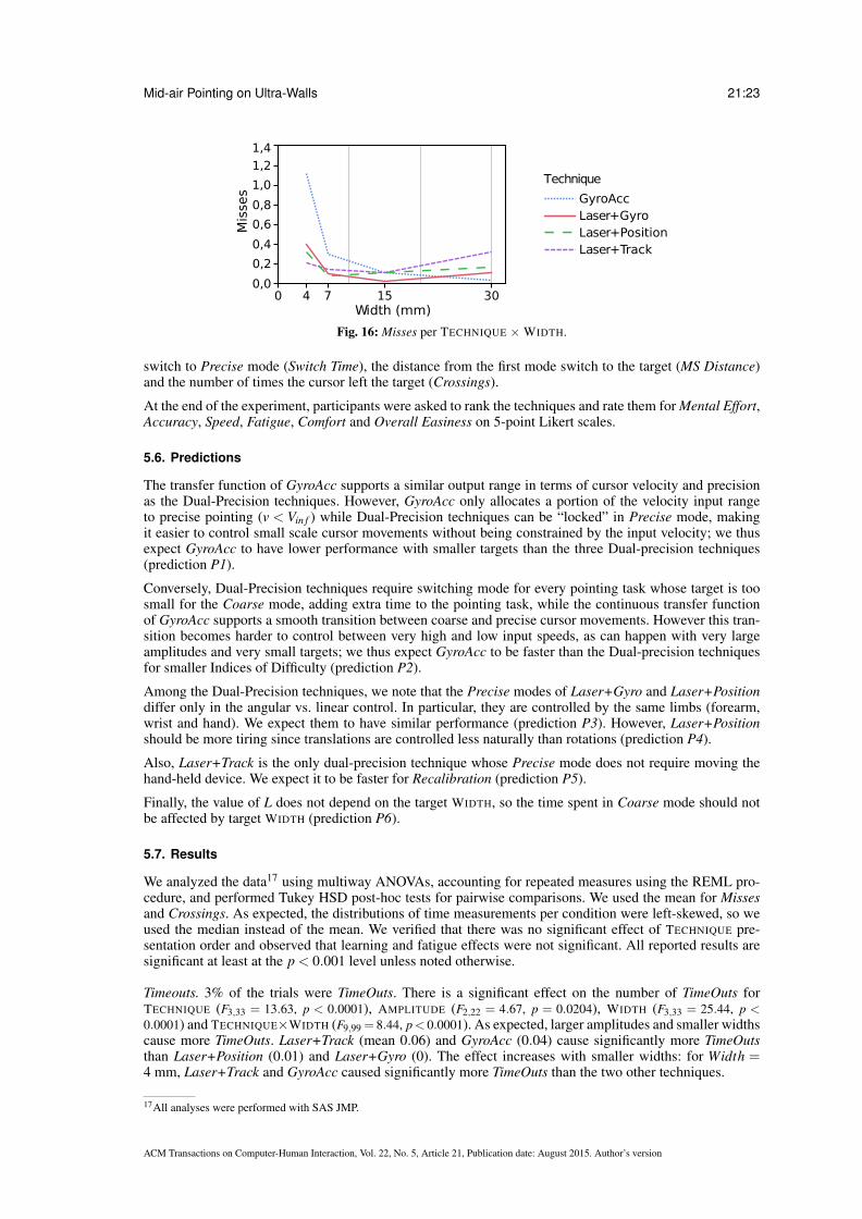
Mid-air Pointing on Ultra-Walls 21:23
0,0
0,2
0,4
0,6
0,8
1,0
1,2
1,4
Width (mm)30
Mis
ses
Technique
GyroAccLaser+GyroLaser+PositionLaser+Track
0 1574
Fig. 16: Misses per TECHNIQUE ×WIDTH.
switch to Precise mode (Switch Time), the distance from the first mode switch to the target (MS Distance)and the number of times the cursor left the target (Crossings).
At the end of the experiment, participants were asked to rank the techniques and rate them for Mental Effort,Accuracy, Speed, Fatigue, Comfort and Overall Easiness on 5-point Likert scales.
5.6. Predictions
The transfer function of GyroAcc supports a similar output range in terms of cursor velocity and precisionas the Dual-Precision techniques. However, GyroAcc only allocates a portion of the velocity input rangeto precise pointing (v < Vin f ) while Dual-Precision techniques can be “locked” in Precise mode, makingit easier to control small scale cursor movements without being constrained by the input velocity; we thusexpect GyroAcc to have lower performance with smaller targets than the three Dual-precision techniques(prediction P1).
Conversely, Dual-Precision techniques require switching mode for every pointing task whose target is toosmall for the Coarse mode, adding extra time to the pointing task, while the continuous transfer functionof GyroAcc supports a smooth transition between coarse and precise cursor movements. However this tran-sition becomes harder to control between very high and low input speeds, as can happen with very largeamplitudes and very small targets; we thus expect GyroAcc to be faster than the Dual-precision techniquesfor smaller Indices of Difficulty (prediction P2).
Among the Dual-Precision techniques, we note that the Precise modes of Laser+Gyro and Laser+Positiondiffer only in the angular vs. linear control. In particular, they are controlled by the same limbs (forearm,wrist and hand). We expect them to have similar performance (prediction P3). However, Laser+Positionshould be more tiring since translations are controlled less naturally than rotations (prediction P4).
Also, Laser+Track is the only dual-precision technique whose Precise mode does not require moving thehand-held device. We expect it to be faster for Recalibration (prediction P5).
Finally, the value of L does not depend on the target WIDTH, so the time spent in Coarse mode should notbe affected by target WIDTH (prediction P6).
5.7. Results
We analyzed the data17 using multiway ANOVAs, accounting for repeated measures using the REML pro-cedure, and performed Tukey HSD post-hoc tests for pairwise comparisons. We used the mean for Missesand Crossings. As expected, the distributions of time measurements per condition were left-skewed, so weused the median instead of the mean. We verified that there was no significant effect of TECHNIQUE pre-sentation order and observed that learning and fatigue effects were not significant. All reported results aresignificant at least at the p < 0.001 level unless noted otherwise.
Timeouts. 3% of the trials were TimeOuts. There is a significant effect on the number of TimeOuts forTECHNIQUE (F3,33 = 13.63, p < 0.0001), AMPLITUDE (F2,22 = 4.67, p = 0.0204), WIDTH (F3,33 = 25.44, p <0.0001) and TECHNIQUE×WIDTH (F9,99 = 8.44, p< 0.0001). As expected, larger amplitudes and smaller widthscause more TimeOuts. Laser+Track (mean 0.06) and GyroAcc (0.04) cause significantly more TimeOutsthan Laser+Position (0.01) and Laser+Gyro (0). The effect increases with smaller widths: for Width =4 mm, Laser+Track and GyroAcc caused significantly more TimeOuts than the two other techniques.
17All analyses were performed with SAS JMP.
ACM Transactions on Computer-Human Interaction, Vol. 22, No. 5, Article 21, Publication date: August 2015. Author’s version
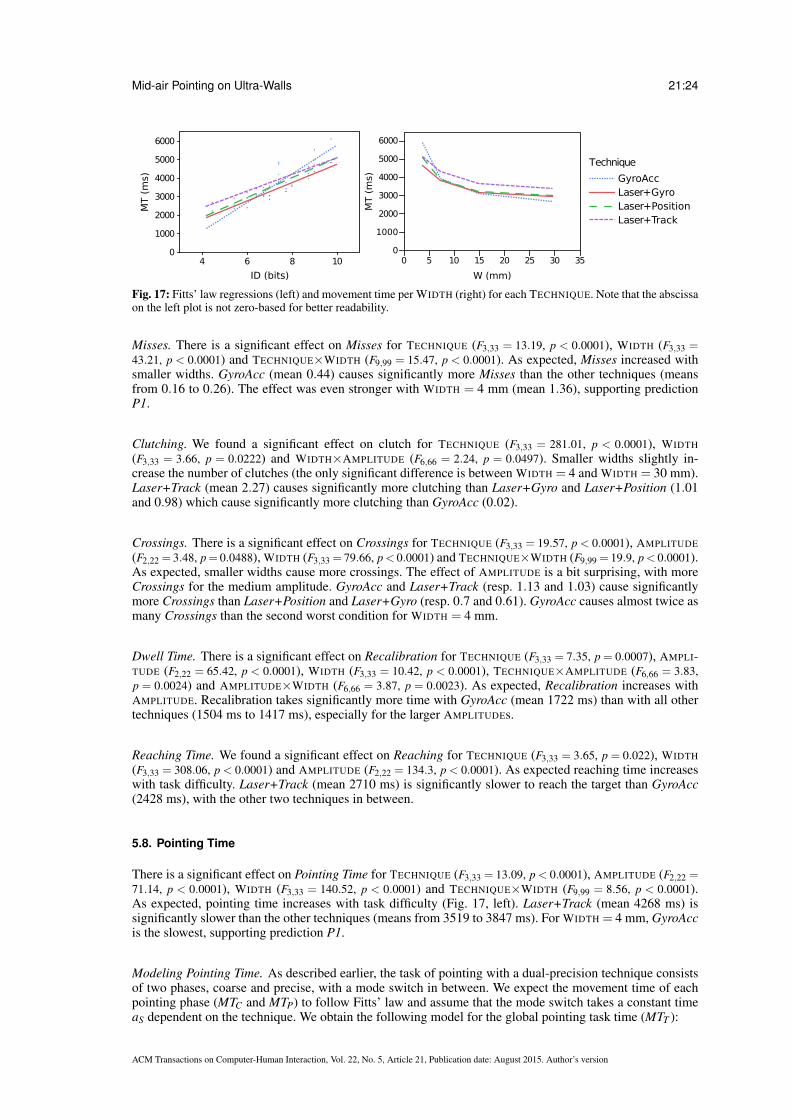
Mid-air Pointing on Ultra-Walls 21:24
1000
2000
3000
4000
5000
6000
4 6 8 100
ID (bits)
MT (
ms)
2000
3000
4000
5000
6000
0 5 10 15 20 25 30 35
W (mm)
MT (
ms)
0
1000
Technique
GyroAccLaser+GyroLaser+PositionLaser+Track
Fig. 17: Fitts’ law regressions (left) and movement time per WIDTH (right) for each TECHNIQUE. Note that the abscissaon the left plot is not zero-based for better readability.
Misses. There is a significant effect on Misses for TECHNIQUE (F3,33 = 13.19, p < 0.0001), WIDTH (F3,33 =43.21, p < 0.0001) and TECHNIQUE×WIDTH (F9,99 = 15.47, p < 0.0001). As expected, Misses increased withsmaller widths. GyroAcc (mean 0.44) causes significantly more Misses than the other techniques (meansfrom 0.16 to 0.26). The effect was even stronger with WIDTH = 4 mm (mean 1.36), supporting predictionP1.
Clutching. We found a significant effect on clutch for TECHNIQUE (F3,33 = 281.01, p < 0.0001), WIDTH
(F3,33 = 3.66, p = 0.0222) and WIDTH×AMPLITUDE (F6,66 = 2.24, p = 0.0497). Smaller widths slightly in-crease the number of clutches (the only significant difference is between WIDTH = 4 and WIDTH = 30 mm).Laser+Track (mean 2.27) causes significantly more clutching than Laser+Gyro and Laser+Position (1.01and 0.98) which cause significantly more clutching than GyroAcc (0.02).
Crossings. There is a significant effect on Crossings for TECHNIQUE (F3,33 = 19.57, p < 0.0001), AMPLITUDE
(F2,22 = 3.48, p= 0.0488), WIDTH (F3,33 = 79.66, p< 0.0001) and TECHNIQUE×WIDTH (F9,99 = 19.9, p< 0.0001).As expected, smaller widths cause more crossings. The effect of AMPLITUDE is a bit surprising, with moreCrossings for the medium amplitude. GyroAcc and Laser+Track (resp. 1.13 and 1.03) cause significantlymore Crossings than Laser+Position and Laser+Gyro (resp. 0.7 and 0.61). GyroAcc causes almost twice asmany Crossings than the second worst condition for WIDTH = 4 mm.
Dwell Time. There is a significant effect on Recalibration for TECHNIQUE (F3,33 = 7.35, p = 0.0007), AMPLI-TUDE (F2,22 = 65.42, p < 0.0001), WIDTH (F3,33 = 10.42, p < 0.0001), TECHNIQUE×AMPLITUDE (F6,66 = 3.83,p = 0.0024) and AMPLITUDE×WIDTH (F6,66 = 3.87, p = 0.0023). As expected, Recalibration increases withAMPLITUDE. Recalibration takes significantly more time with GyroAcc (mean 1722 ms) than with all othertechniques (1504 ms to 1417 ms), especially for the larger AMPLITUDEs.
Reaching Time. We found a significant effect on Reaching for TECHNIQUE (F3,33 = 3.65, p = 0.022), WIDTH
(F3,33 = 308.06, p < 0.0001) and AMPLITUDE (F2,22 = 134.3, p < 0.0001). As expected reaching time increaseswith task difficulty. Laser+Track (mean 2710 ms) is significantly slower to reach the target than GyroAcc(2428 ms), with the other two techniques in between.
5.8. Pointing Time
There is a significant effect on Pointing Time for TECHNIQUE (F3,33 = 13.09, p < 0.0001), AMPLITUDE (F2,22 =71.14, p < 0.0001), WIDTH (F3,33 = 140.52, p < 0.0001) and TECHNIQUE×WIDTH (F9,99 = 8.56, p < 0.0001).As expected, pointing time increases with task difficulty (Fig. 17, left). Laser+Track (mean 4268 ms) issignificantly slower than the other techniques (means from 3519 to 3847 ms). For WIDTH = 4 mm, GyroAccis the slowest, supporting prediction P1.
Modeling Pointing Time. As described earlier, the task of pointing with a dual-precision technique consistsof two phases, coarse and precise, with a mode switch in between. We expect the movement time of eachpointing phase (MTC and MTP) to follow Fitts’ law and assume that the mode switch takes a constant timeaS dependent on the technique. We obtain the following model for the global pointing task time (MTT ):
ACM Transactions on Computer-Human Interaction, Vol. 22, No. 5, Article 21, Publication date: August 2015. Author’s version

Mid-air Pointing on Ultra-Walls 21:25
MTT = MTC +aS +MTP (27)
= (ac+aS+ap)+bc log(
1+AL
)+bp log
(1+
dW
)(28)
= a+bc IDC +bp IDP (29)
Using our model with L =√
2AmaxWmin and d = L/2 (Eq. 16), we compute the following regressions andgoodness of fit:
Model Technique Parameters r2 AICcLaser+Gyro −226+466× IDC +633× IDP .96 168
Our model Laser+Position −309+423× IDC +745× IDP .93 178Laser+Track 601+348× IDC +640× IDP .92 175Laser+Gyro −205+496× ID .93 170
Fitts’ law Laser+Position −361+534× ID .86 181Laser+Track 540+454× ID .85 178
GyroAcc −1972+772× ID .81
Table II: Parameters and accuracy of both Fitt’s law and our model. GyroAcc is a single-mode technique and thereforeour model does not apply.
In accordance with the findings in [Shoemaker et al. 2012], the goodness of fit (r2 = .96 for Laser+Gyro,.93 for Laser+Position and .92 for Laser+Track) is consistently better than when modeling the global tasktime with Fitts’ law (r2 = .93 for Laser+Gyro, .86 for Laser+Position and .85 for Laser+Track). Since thiscould be due to our model having two parameters instead of one, we computed the Akaike InformationCriterion with correction (AICc)18[Akaike 1974]. The results confirm that our model provides a better fit.
Table II shows a wide range of intercepts for the various regressions, including some negative ones. How-ever we cannot interpret these intercepts because we cannot extrapolate these regressions to low IDs. Inparticular, low-ID tasks can be performed with Dual-Precision techniques using only their Coarse mode,which our model does not take into account. Fig. 17 (left) shows the Fitts’ law regressions, allowing us tocompare all four techniques. We see that, for the range of IDs that we tested, Laser+Gyro and Laser+Trackhave comparable throughputs with a consistent disadvantage for Laser+Track. Laser+Position has a slightlylower throughput and is in between the other two techniques. Finally, GyroAcc has the lowest throughput.It is the fastest for low IDs and the slowest with high IDs, supporting both prediction P1 and prediction P2.Fig. 17 (right) shows the average movement time for each target width and is therefore independent of themodel we choose. It shows the same pattern: Laser+Gyro is, overall, faster, with GyroAccfaster for largetargets, but much slower than any other technique for small targets.
Focusing on our model, we observe that for the Dual-Precision techniques bp is consistently higher than bc,with a ratio r = bp/bc of 1.36, 1.76 and 1.84 respectively for Laser+Gyro, Laser+Position and Laser+Track.Users seemed to have more difficulty with the Precise mode, maybe due to mental readjustment caused bythe change of input modality from Coarse to Precise. This is inconsistent with our assumption that Fitts’law parameters a and b are the same in both phases (Section 4.1, page 11). Future work should thereforestudy the effect of L on performance and fine tune the a priori value of r from preliminary evaluations ofeach mode separately. However, we observe that our approach resulted in a set of techniques that allowedall participants to perform the hardest pointing tasks in less than 6 seconds on average.
5.9. Mode Switches
In order to better understand the effect of the three dual-mode techniques on performance, Laser+Gyro,Laser+Position and Laser+Track, we performed a detailed analysis of mode switches.
Despite our instructions, some participants chose not to switch mode for some trials (5 %) and perform thetask in Coarse mode only. We observe a significant effect of WIDTH (F3,33 = 4.13, p = 0.0136), AMPLITUDE
(F2,22 = 5.8, p = 0.0095) and WIDTH×AMPLITUDE (F6,66 = 5.12, p = 0.0002) on the number of such “coarse-only” trials. Unsurprisingly, participants performed more coarse-only trials with the largest targets WIDTHs(30 mm) than with the the smaller ones (4 and 7 mm). More interestingly, participants performed more
18This criterion measures the relative goodness of fit of a statistical model and assesses overfitting, i.e., increasing the number of freeparameters to improve the goodness of fit.
ACM Transactions on Computer-Human Interaction, Vol. 22, No. 5, Article 21, Publication date: August 2015. Author’s version

Mid-air Pointing on Ultra-Walls 21:26
GyroAcc Laser+GyroLaser+PositionLaser+Track
Mental Effort
Very low
Low
NormalHigh
Too high
Accurate pointingVery difficult
Difficult
Normal
Easy
Very easy
Speed
Slow
Normal
Fast
General comfort
Uncomfortable
Normal
Comfortable
Very comfortable
Overall easinessVery difficult
Difficult
Normal
Easy
Very easy
Ranking
Worst
3rd
2nd
Best
Fig. 18: Mosaic plot of the qualitative results from Exp. 2. The height of a box represents the number of participants thatused this grade or rank overall (regardless of technique). The width of a box represents the proportion of a particulargrade or rank for a given technique.
coarse-only trials with the smallest AMPLITUDE (637 mm) than with the other two. Finally, the small ampli-tude × small target condition caused significantly more coarse-only trials than any other condition. In thefollowing analyses of mode switch occurrences we removed the trials with no mode switch.
Switch Time and MS Distance measure respectively the time and distance to target of the first mode switch.We consider that the mode switch was an error when performed at a distance greater than trials 3×L. Suchtrials (13 %) were excluded from the analyses.
We observed no significant effect of TECHNIQUE on Switch Time. Unsurprisingly, Switch Time increasessignificantly with AMPLITUDE (F2,20.86 = 147.96, p < 0.0001). However we also found a significant effect ofWIDTH (F3,32.33 = 8.84, p = 0.0002), in contradiction with prediction P6. This is surprising since the size ofthe Coarse mode “target”, L, does not depend on the actual target WIDTH. The post-hoc test reveals thatusers switch modes later for smaller targets (WIDTHs = 4 and 7 mm) than for larger ones (15 and 30 mm).
Similarly, we did not observe any effect of TECHNIQUE on MS Distance. We note that the actual distancebetween the first mode switch and the target is always lower than our conservative estimate of L/2 = 80 mm(mean 27.7 mm, stdev 23.2). This is to be expected since we calculated L as a higher bound for MS Distance,to define the visual size of the cursor. We did observe, however, a significant effect of TECHNIQUE for WIDTH
(F3,32.69 = 4.72, p = 0.0076) and AMPLITUDE (F2,21.99 = 9, p = 0.0014). Participants switched mode furtheraway from the target with larger AMPLITUDE (3187 and 1912 mm) than with the smaller one (637 mm).Participants also switched mode further away with the largest target (30 mm) than with the smaller ones (4and 7 mm).
We computed the time spent in Precise mode as Precise Time = Pointing Time - Switch Time and founda significant effect of TECHNIQUE (F2,19.19 = 11.57, p = 0.0005) and WIDTH (F3,28.33 = 81.48, p < 0.0001).Unsurprisingly, Precise Time with targets of 4 mm were higher than targets of 7 mm, which were higher thantargets of 15 and 30 mm. More interestingly, Laser+Gyro caused shorter Precise Time than Laser+Positionand Laser+Track.
Finally, we observed that Switch Time follows Fitts’ law with the model Switch Time = a + b ×log2
(1+ Amplitude
L
)with goodnesses of fit equal19 to 1 for Laser+Gyro and Laser+Position and 0.99 for
Laser+Track.
5.10. Qualitative results
A Pearson χ2 test shows that there is a significant effect on Mental Effort, Accuracy, Comfort, Easinessand Ranking for TECHNIQUE. 6 participants graded mental effort for Laser+Track as High or Too high,
19Rounded at two decimals.
ACM Transactions on Computer-Human Interaction, Vol. 22, No. 5, Article 21, Publication date: August 2015. Author’s version

Mid-air Pointing on Ultra-Walls 21:27
and all 12 graded all other techniques Normal (3) or below. 6 participants graded precise pointing withLaser+Track and GyroAcc as Difficult or Very difficult and 9 graded it Easy or Very easy with Laser+Gyroand Laser+Position.
10 participants graded Laser+Track Uncomfortable or Very uncomfortable. 10 and 7 participants respec-tively graded Laser+Gyro and Laser+Position as Comfortable or Very comfortable, partially supportingprediction P4 . 10 participants graded Laser+Position and Laser+Gyro as Easy or Very easy and 10 gradedLaser+Track as Normal (3) or below. Finally, 8 participants preferred Laser+Gyro overall, 2 preferredLaser+Position, 2 preferred GyroAcc and none preferred Laser+Track. Overall, these results are consistentwith the quantitative analysis.
5.11. Discussion
5.11.1. Coarse and Precise phases. Based on these results, we hypothesize that users adapt their Coarsepointing phase according to the expected difficulty of the Precise phase in order to optimize general pointingtime. Indeed, despite being functionally unrelated to target WIDTH, the Coarse phase lasted longer with, andended closer to, the smaller targets. We presume that this behavior was intended to make smaller targetseasier to acquire by lowering the amplitude of the Precise phase. Participants also switched modes closerto the target when the AMPLITUDE was smaller, possibly capitalizing on a normally shorter Coarse phase toswitch mode closer to the target.
Despite comparable Switch Time and MS Distance, participants spent less time in Precise mode withLaser+Gyro than with the other two Dual-Precision techniques. We hypothesize that this is due to theangular control of the Precise mode of Laser+Gyro being similar to that of the Coarse mode (ray-casting),whereas the Precise mode of Laser+Position and Laser+Track both involves linear control and differentlimbs. Also, participants sometimes avoided switching to Precise mode for small AMPLITUDE and large tar-get WIDTH. We hypothesize that they tried to minimize pointing time by saving the cost of both switchingmode and adapting their input to the Precise phase control.
Technique GyroAcc Laser+Track Laser+Gyro Laser+PositionTimeouts – – ++ +Misses – + + +Clutching ++ – + +Crossings – - + +Dwell – + + +Reaching – ++ o oPointing + lowID – o o
- HighIDMental Effort –Precision – – ++ ++Comfort –Easy o ++ ++Preference + – ++ +
Table III: Overall assessment of the techniques on a five-point scale (“–”, “-”, “o”, “+”, “++”).
5.11.2. Techniques. Table III summarizes the quantitative and qualitative results by ranking the tech-niques on a five-point scale.
GyroAcc was generally perceived as imprecise, which is consistent with the qualitative results. More pre-cisely, despite the fact that it was the fastest technique to reach the target, it caused more crossings andmisses than the other techniques, especially with very small targets. This indicates that users could easilyperform fast, coarse pointing but that stabilizing the cursor over a small target was difficult. However, Gy-roAcc performed well in both speed and accuracy for WIDTHs 7 mm and larger, indicating that pointingtasks of this difficulty can be performed without using a Dual-Precision technique to explicitly trade speedfor precision.
Laser+Track was the slowest and least preferred technique overall. Despite having the same Coarse modeas the other dual-precision techniques, it was the slowest for Reaching; it also caused many Clutching andCrossings, meaning that the Precise mode is neither precise nor fast enough to compete with other dual-precision techniques. In addition, it was not better for recalibration time, contradicting prediction P5 (weexpected that its Precise mode would cause smaller displacements of the absolute cursor). These results areconsistent with the participants’ opinion: hard to use, imprecise and uncomfortable. This may be due in partto the following problem: 5 participants reported that lifting the finger from the tracking zone of the device
ACM Transactions on Computer-Human Interaction, Vol. 22, No. 5, Article 21, Publication date: August 2015. Author’s version

Mid-air Pointing on Ultra-Walls 21:28
(zone 1 in Fig. 11) caused a loss in precision despite our finger-release adjustment, and that they wouldhave preferred a physical button. An improvement could be to implement the Precise mode of Laser+Trackwith an input device that couples finger tracking with physical actuators, such as Apple’s Magic Mouse orMicrosoft’s Touch Mouse.
Laser+Gyro and Laser+Position had very similar results, supporting prediction P3. They caused almostno TimeOuts, meaning that they were able to withstand very difficult tasks such as those in the experiment.They were also the most stable (best for Crossings) and fastest techniques overall. They were both perceivedas precise, comfortable and easy to use. Laser+Gyro was the preferred technique and had a slight advantagewhen pointing at very small targets, which is consistent with prediction P2.
It is interesting to note the sudden decrease in performance of GyroAcc for the smallest targets. We hypoth-esize that there is a limit to the output range of continuous transfer functions above which the steepness ofthe curve makes it difficult to control the transition between fast and precise movements. While this partic-ular theory should be evaluated further, we can at least observe that Dual-Precision techniques do not havesuch a limitation since the transition between modes is discrete: there is no need for a smooth transitionbetween the ranges of CD gains used in Coarse and Precise modes. Eq. (23) shows that, in most cases, thetheoretical limit of difficulty of dual-precision techniques (18.97 for Laser+Gyro, i.e., targets of 0.01 mmon a 5.5-meter ultra-wall) is higher than human visual acuity.
Finally, it is worth noting that despite their relative differences, all techniques enabled participants to reliablyperform pointing tasks with IDs up to 9.6 bits, a difficulty never evaluated before in a single-scale pointingstudy. This demonstrates the effectiveness of our design approch and theoretical analysis of unimanualDual-Precision and Pointer Acceleration pointing techniques. The next section applies a similar method todesign and evaluate touch-based pointing techniques that minimize input resources.
6. STUDY 2: SINGLE- VS. DUAL-CHANNEL TECHNIQUES USING TOUCH DEVICES
Fig. 19: Interacting with an ultra-wall using a tablet that features both control widgets and an area dedicated to high-precision remote pointing (top-left).
In this section we focus on techniques that can be used on a small portion of a touchscreen so that otherwidgets can be displayed simultaneously. We consider contexts of use where the primary purpose of thehandheld device is to accommodate widgets for the advanced control of objects selected via pointing. Thephysical area dedicated to pointing on the device, or pointing zone, should therefore not be too large. How-ever, if too small, pointing will be inefficient. Our goal is to identify the best trade-off between screenreal-estate allocation and good pointing performance.
In Section 3.2 we demonstrated that a smartphone screen does not provide enough input resolution to acquiresmall (visible) targets on an ultra-wall with a constant CD gain, and that the full size of a tablet screen wouldhave to be used for this purpose. However we would like to use the smallest area possible for input on thedevice (tablet or smartphone) to allow for other interactions. Thus, more than one CD gain is required.To address this problem we explore two ways to augment the input expressiveness of a touch area withDual-Precision techniques (Section 4.1): using an additional input channel, and distinguishing between twomodes when touching the handheld.
ACM Transactions on Computer-Human Interaction, Vol. 22, No. 5, Article 21, Publication date: August 2015. Author’s version

Mid-air Pointing on Ultra-Walls 21:29
6.1. Techniques
We showed in the previous sections that the main challenge when designing Dual-Precision techniques isto seamlessly integrate the two modes so that the mode switch minimizes cognitive and/or motor costs. Allthe techniques presented in this section assign the Precise mode to single-finger drag gestures performedwith the dominant hand in the pointing zone of the handheld device. Since the non-dominant hand typicallyholds the device [Wagner et al. 2012], this leaves two main options for the Coarse mode:
— Use the dominant hand in both modes but in two different configurations that are easily distinguishableby the system and the user;
— Use a different body part for the Coarse mode, that does not impair the control of the Precise mode.
We experimented with several options and identified two viable assignments for the Coarse mode throughiterative design, prototyping, piloting and tuning: double-finger drag gestures with the dominant hand in thehandheld’s pointing zone, and tracking the head orientation. Both approaches are detailed below.
6.1.1. Two-finger pad-based coarse pointing. This approach is inspired by ARC-Pad [McCallum and Irani2009], a pointing technique that provides users with an absolute and a relative pointing mode. A typicalARC-Pad pointing task is composed of a tap (press-release) on a touch-sensitive handheld device, followedby a dragging gesture. The tap gesture coarsely positions the cursor on the large display according to anabsolute mapping of the handheld device’s surface to the large display. The following drag gesture is inter-preted as relative movements of the cursor to adjust its position. Tapping vs. dragging is a practical way ofdifferentiating the user’s intention between coarse and precise cursor control, and was proven efficient on a52” screen with a resolution of 1360×768 pixels. However, this approach does not scale: when mapping a7 cm input device to a 5 meter display, a 1 millimeter error in the tap location corresponds to a 7.5 cm erroron the display, resulting in multiple dragging gestures to reach the target. ARC-Pad proved very difficultto use on ultra-walls, mainly because in that context the absolute mapping is far too imprecise and oftenrequires either several attempts (taps) in Coarse mode to move the cursor close enough to the target, or sev-eral relative-mode drag gestures to adjust the cursor position, causing much clutching in the second phase.We thus adapted the original technique so that users can adjust the location of their cursor in Coarse mode.We call this variation of the original technique ARC-Pad220.
ARC-Pad2 distinguishes between Coarse (absolute) and Precise (relative) pointing by the number of fingersinvolved in performing the pointing gestures rather than by the type of gesture. A single-finger drag gesturecontrols the cursor in Precise mode (as before); a drag gesture performed with two conjoined fingers [Kinet al. 2011] is interpreted as absolute positioning of the cursor. As opposed to the original method that reliedon tap gestures for absolute mapping, users can now adjust the cursor position in Coarse mode as well bydragging the two fingers, and then switch to Precise mode for more precise, relative adjustments of thecursor position. The switch from Coarse to Precise mode is triggered whenever at least one of the fingersis lifted from the pad’s surface. This means that users can either lift a single finger at the current locationand continue dragging, or they can lift both fingers, adjust their hand position relative to the pad, and touchanywhere on the surface with a single finger. This second option can be very useful when pointing at a targetnear the edges of the display, as it lets users initiate relative drag gestures from the center of the pointingzone, in any direction.
We also considered the symmetric approach, i.e. one finger for coarse pointing and two for precise pointing,but preliminary tests showed that lowering a second finger in order to switch to Precise mode may causethe second finger to fall out of the input area when the target is near the display borders. This has either noeffect if the finger did not reach an interaction widget outside the pointing area, or it can trigger unwantedcommands. In both cases users may wonder why lowering their finger did not have the expected effect andlook at the input device, thus losing their focus. Leaving the input area when using two fingers is less likelyto happen in Coarse mode since it uses an absolute mapping: users always have a feedback of their fingers’location on the input area through the position of the cursor on the display.
6.1.2. Head-based coarse pointing. The second viable approach that we identified for Coarse controluses the natural head movements that occur when remotely pointing at targets on a wall.
Object selection is often preceded by a visual search when the target is not located in the user’s immediatefield of view. Head orientation provides a good approximation of where a user is looking [Stahl 1999; Freed-man and Sparks 2000; Nickel and Stiefelhagen 2003]. Head movements can also be exploited in conjunctionwith any positioning device used in the environment [Kitajima et al. 2001; Nickel and Stiefelhagen 2003]
20ARC-Pad2F in [Nancel et al. 2013]
ACM Transactions on Computer-Human Interaction, Vol. 22, No. 5, Article 21, Publication date: August 2015. Author’s version

Mid-air Pointing on Ultra-Walls 21:30
(a) (b)
αβ
α<β
α β
α=β
Fig. 20: Varying angular motor size with ray-casting (a) can be fixed using an indirect absolute mapping (b).
and has been shown to support a variety of interaction techniques [Kitajima et al. 2001; Morency and Dar-rell 2006; Kollerl et al. 1996]. Our approach integrates head motion with cursor selection. It was inspired by[Ashdown et al. 2005], who use head orientation for positioning a cursor on the monitor of interest, therebyreducing mouse trips in a multi-monitor setup. We provide a framework for designing target selection tech-niques that use head orientation, based on the results of a study of head and body orientation when acquiringtargets in mid-air on an ultra-wall [Nancel 2012, App. C].
[Stellmach and Dachselt 2012] took a similar approach using gaze instead of head orientation. They intro-duce four techniques that follow a common design guideline: gaze suggests, touch confirms. While theirresults are promising, they did not compare their design with existing techniques, and only evaluated it indesktop environment. Wall-sized displays feature much greater sizes than desktop screens, regardless ofpixel density. While desktop screens can often be skimmed through with minimal movement other than theeyes’, wall-sized displays may require much larger head rotations, as discussed in Section 3.1. Confirmingprior work [Jacob 1991; Zhai et al. 1999], [Nancel 2012, App. C] observed that users consistently stabilizetheir gaze and lock it on the target while acquiring it. While tracking the users’ gaze is not a practical optionin our context, we found head orientation to be a good coarse indirect indicator of where users are looking21,and thus a good predictor of the rough location of the next target on the display.
Our technique controls the cursor’s location in Coarse mode through an absolute but indirect mapping ofhead orientation to cursor position on the wall. We favored an indirect mapping over direct ray-casting(or laser pointing) for two reasons. First, being based on angular movements, ray-casting is perspective-dependent and would have caused targets of the same size on the display to have noticeably different motorsizes depending on their location with respect to the user’s physical position, as illustrated in Fig. 20-a(this effect gets amplified as users get closer to the display). We also wanted to optimize the users’ inputoperating range, within the limits of comfortable neck and eyes positions.
As illustrated in Fig. 20-b, we addressed these issues by mapping a location-independent, fixed-size angularoperating range centered on the orthogonal projection of the user’s location on the flat display surface. Thisensures that when users move in front of the display, looking straight ahead always sets the cursor exactlyin front of them. As they look away, the cursor is progressively offset from the direction of the head (up to12.5◦, see Fig. 21), accounting for the extra rotation of the eyes. This offset makes it possible to point attargets on the sides of the wall comfortably while maximizing accuracy in the central area.
-40°
-20°
40°-20° 20°-40°Head
Orientation
40°
20°
Cursor angle
Fig. 21: Angular abscissa of the cursor as a function of the horizontal orientation of the head. The maximum offset(plain red line), i.e. the difference between the head orientation and the cursor angle, is 12.5◦.
This is an absolute yet indirect technique with a constant transfer function: all targets with the same displaysize have the same motor size. Its precision directly depends on the operating range of the input channel,which is limited by the angular range of head orientation that users can reach without stretching their neck
21When a target is off-centered relative to the default head position, users rotates their head in order to minimize the effort put onocular muscles [Freedman and Sparks 2000].
ACM Transactions on Computer-Human Interaction, Vol. 22, No. 5, Article 21, Publication date: August 2015. Author’s version

Mid-air Pointing on Ultra-Walls 21:31
too much and with minimal difference between eye and head orientation. Increasing the angular operatingrange makes small targets easier to acquire, but amplitudes become larger. This technique facilitates mid-airinteractions when the user moves around the room, since target motor size does not depend on the distanceto the wall.
6.1.3. Quantized coarse pointing. In the first study (Section 5) we observed that users changed theirbehavior in Coarse mode depending on the apparent relative difficulty of the Precise phase. Participantstypically spent more time adjusting the location of the mode switch when the Precise phase looked chal-lenging (i.e. smaller targets) or when the Coarse phase looked easy (i.e. small pointing amplitude). In theeasiest cases they even skipped the Precise phase and achieved the selection in Coarse mode only. Howeverthis optimization behavior occurred in only 5 % of the trials and did not significantly improve performance.
The Coarse phase was originally designed to embody the initial, ballistic phase of a pointing task. Whilefast, unconstrained Coarse movements showed signs of accuracy optimization and thus of additional cog-nitive cost. This raises a question: beyond minimizing the motor cost of switching between modes, is itpossible to minimize the cognitive cost associated with making the decision to switch between the twomodes?
We explored an approach where the cognitive load is transferred to the perceptual system, hypothesizingthat this would significantly reduce the switching cost. We designed variations of the techniques describedabove that artificially limit the precision of the Coarse pointing mode: users approach the target fast andknow when to switch to Precise mode simply because there is no other option. We discretize the displayaccording to a set of cells, in our case the 8×4 matrix of 30” LCD panels, so that in Coarse mode userscan only jump from cell to cell. Adopting the physical subdivision of the wall into display tiles ensuresthat cells do not intersect the screen edges; Subdividing the screens further would either lead to cells withaspect-ratios different from that of the input zone, or too small to be accurately acquired in Coarse mode.We call this process discretization to emphasize the fact that the pointing resolution in Coarse mode isartificially degraded while keeping the same physical input resolution.
The resulting technique is reminiscent of the Rake cursor [Blanch and Ortega 2009; Raiha and Spakov 2009]and similar multi-cursor desktop pointing techniques that use eye gaze to select the active cursor in a matrixof cursors all controlled with the same input device. However our technique always relocate the cursor atthe center of the currently head-pointed cell when in Coarse mode, as opposed to keeping its last Preciselocation relative to the cell: Although we expected users to remember where they left the cursor when theylast switched to Coarse mode, our tests showed otherwise. We found that having the Precise cursor start inthe middle of the cell yields better performance and is less demanding. It also results in a constant averagedistance between the cursor and the targets in that cell. Once the cell containing the target is selected, usershave to switch to Precise mode to reposition the cursor within that cell.
6.1.4. Four Dual-Precision pointing techniques. We eventually narrowed our design down to four pointingtechniques by combining the two coarse input control techniques (pad-based vs. head-based) with twoCoarse mode input precisions (Continuous vs. Discrete). As mentioned earlier, all four techniques use thehandheld device’s pointing zone to control the cursor in Precise mode using an optimized CD gain transferfunction.
— ARC-Pad2 + Continuous = ContPad: two conjoined fingers in the handheld’s pointing zone activateCoarse mode (absolute mapping of the zone to the wall); a single finger activates Precise mode (relativecursor displacements).
— ARC-Pad2 + Discrete = DiscPad: same as ContPad but pointing precision in Coarse mode is artificiallyrestricted: the cursor can only move to the center of a cell, requiring a switch to Precise mode for furthercursor adjustments.
— Head + Continuous = ContHead: head orientation provides Coarse control of the cursor. Touching thepointing zone on the handheld automatically switches to Precise mode (relative cursor displacements).
— Head + Discrete = DiscHead: same as ContHead, but pointing precision in Coarse mode is artificiallyrestricted. Head orientation can only make the cursor jump to the center of a cell, as for DiscPad.
With the two ARC-Pad2 techniques, the cursor only moves if one or two fingers touch the screen, allowingusers to easily perform clutch and tap gestures. For the two Head-based techniques, Coarse mode is thedefault mode: as long as the user does not touch the handheld screen, the cursor follows the user’s headmovements. Head-based techniques also feature a 500 ms delay after the finger is released from the hand-held screen before switching back to Coarse mode, letting users perform clutch and tap gestures in Precisemode.
ACM Transactions on Computer-Human Interaction, Vol. 22, No. 5, Article 21, Publication date: August 2015. Author’s version

Mid-air Pointing on Ultra-Walls 21:32
(A) (B) (C)Discrete Continuous
AR
C-P
ad2
Hea
d
Switch to relative
Fig. 22: The four Dual-Precision techniques. (A) The three combinations of device and pointing zone used in ourexperiments: tablet with large zone (Experiments 1 and 3), smartphone with small zone (Experiment 2) and tablet withsmall zone (Exp. 3). (B) The four coarse (absolute) modes, combinations of Head vs. ARC-Pad2 and Discrete vs.Continuous. (C) In all cases, using a single finger in the pointing area switches to precise (relative) mode.
To calibrate the transfer functions, we followed the procedure described in Subsection 8.2 and asked threevolunteers to test the techniques in an informal iterative design process of 800 pointing trials per useron average. Table IV gives the parameter values that we obtained after extensive pilot testing for the twopointing zones that served in the experiments reported below: a large zone that fits a tablet screen in portraitmode and a small zone that fits a smartphone screen in landscape mode.
Size Technique CDmax λ (s/mm) ratioin f
Largezone148 × 49
(mm)
ContHeadL 9.9 .02 0.4ContPadL 6.6 .018 0.4
DiscHeadL 12.9 .018 0.4DiscPadL
Smallzone75 × 26
(mm)
ContHeadS 6.3 .027 0.4ContPadS
DiscHeadS 16.4 .027 0.7DiscPadS
Large zone: Vmin = 0.006m/s, Vmax = 0.37m/s, CD gainmin = 0.22Small zone: Vmin = 0.003m/s, Vmax = 0.19m/s, CD gainmin = 0.27
Table IV: Transfer function parameter values.
Vmin and Vmax are lower for the small zone because users have less physical (motor) space at their disposalfor pointing, and thus less amplitude to accelerate. Similarly, the small zone features a higher CD gainmax,enabling faster cursor movements to compensate for the smaller operating range. Discrete techniques featurea higher CD gainmax than Continuous ones to compensate for the larger distance between the target and thepoint where mode switching is performed.
Fig. 23: Cursor of the Discrete techniques in Coarse mode. The precise cursor (red cross) is located at the center ofthe screen currently pointed at, which is highlighted (white, 5% translucency). A translucent proxy (white circle, 2%additional translucency) indicates the location of the continuous pointing input in order to enable users to anticipatewhen the pointed screen will change.
ACM Transactions on Computer-Human Interaction, Vol. 22, No. 5, Article 21, Publication date: August 2015. Author’s version

Mid-air Pointing on Ultra-Walls 21:33
6.1.5. Cursor Feedback. We use a red cross for the cursor and additional feedback in Coarse mode.For the Continuous techniques we surround the cursor with a red circle. As in the experiment reported inSection 5, the size of the circle is computed using Eq. (19) and gives users an indication of when to switchto Precise mode.
For the Discrete techniques, in Coarse mode the visible cursor is a red cross always located at the centerof the pointed cell, which is slightly highlighted (Fig. 23). Preliminary tests showed that users also need toknow how close they are to switching cells, otherwise flickering may happen when the cursor is movingback and forth over the edge between two cells. We added a translucent disc (Fig. 23) to provide feedbackabout the exact, continuous location pointed to by the Coarse technique so that users know how close theyare to the edge of the current cell. We tried other solutions such as highlighting the border of the cell whenthe user is about to change cell, but they require more attention to be understood than a simple proxy of thepointed location. To reduce clutter and since they are not critical to the pointing task, the screen highlight andthe proxy of the continuous pointing location are displayed with low opacity (5% for the screen, combinedwith 2% for the proxy).
6.2. Comparing the Techniques
We conducted two experiments to evaluate the performance of the four Dual-Precision pointing techniquesintroduced above, ContHead, ContPad, DiscHead and DiscPad, and to assess the cost of mode switching.The two experiments followed the same design but involved two different devices and input sizes: we useda tablet with a large pointing zone in the first experiment, and a smartphone with a small pointing zone inthe second one. For the sake of clarity, we use subscripts L (Large) and S (Small) when referring specificallyto the tablet vs. smartphone conditions, e.g. ContHeadL and ContHeadS.
Our hypotheses are as follows:
(H1) Discrete techniques reduce the cognitive cost of mode switching by leaving no choice to usersabout when to switch mode, leading to a shorter Coarse pointing phase than Continuous techniques.
(H2) Head-based techniques make mode switching cognitively less demanding, as they use differentbody parts to control the two modes. Pad-based techniques use the fingers in both modes and for modeswitching. With Head-based techniques, a mode switch is triggered when the finger comes into contactwith the pointing zone.
Related to (H1), we expect an effect of forcing the mode switch with Discrete techniques on the time spentin the Precise phase, since this often entails engaging the Precise mode significantly farther away from thetarget than with Continuous techniques.
We also expect to observe relative differences between the two experiments due to the smaller pointing zoneused in the second one: we expect Head-based techniques to be at an advantage in the second experiment,as the smaller size of the pointing zone will hinder performance of Pad-based techniques in Coarse mode.
6.2.1. Participants. The same 12 participants (2 female; 24 to 38 year-old, avg. 29.6, med. 28.5) servedin both experiments. All had normal or corrected-to-normal vision and were right-handed. All were dailyusers of personal computers and smartphones. Only two used tablets regularly.
6.2.2. Apparatus. Both experiments were conducted on the same WILD platform as the first experiment.We used the VICON motion-capture system to track passive IR retroreflective markers and provide the3D coordinates of the participant’s head. Participants stood up, 2 meters away from the display. Giventhis position and the size of the wall, the operating range of the head was π/2 rad horizontally ×π/5 radvertically. For the Discrete techniques, the cells correspond to the physical screens of the display (8×4 cellsof 2760×1800 pixels or 637 mm×415 mm).
6.2.3. Trials. The task consists of acquiring circular targets of two WIDTHs: 4 mm (18 pixels) and 18 mm(80 pixels). Participants first move the cursor in Coarse mode to a dedicated zone (a cell for the Discretetechniques, a 500-pixel circle for the Continuous techniques) symmetric to the target location from thecenter of the display (see Fig. 24) and dwell for half a second. Then they acquire the target, located at one ofthree AMPLITUDEs: 2 760 pixels (width of one LCD panel, 0.637 m), 8 280 pixels (width of 3 LCD panels,1.912 m), 13 800 pixels (width of 5 LCD panels, 3.187 m). The corresponding Index of Difficulty rangesfrom 5.19 to 9.64 bits.
For each AMPLITUDE, we use six combinations of starting and ending screens around the center of thedisplay (Fig. 24) so that the dwell zone is never located in the same screen as the previous target. Targets
ACM Transactions on Computer-Human Interaction, Vol. 22, No. 5, Article 21, Publication date: August 2015. Author’s version

Mid-air Pointing on Ultra-Walls 21:34
Fig. 24: Location of the six targets in all three experiments for each AMPLITUDE. Colors were changed for readability:the experiment background was black and all targets were green. Targets are also represented much larger than theywere in the experiment.
are pseudo-randomly positioned within a screen so that the average distance from the center of that screento the target is about 600 pixels (150 mm). We chose this value so as to neither advantage nor disadvantageDiscrete techniques (relative to the size of a screen), given that those techniques position the cursor at thecenter of the most recently visited LCD panel.
6.2.4. Design and Procedure. Both experiments use a 4×2×3 within-subject design with three factors:
(1) TECHNIQUE: ContHead, ContPad, DiscHead and DiscPad
(2) WIDTH: 4 mm (18 pixels) and 18 mm (80 pixels);
(3) AMPLITUDE: 637 mm (2 760 pixels), 1 912 mm (8 280 pixels) and 3 187 mm (13 800 pixels)
The trials are blocked by TECHNIQUE and the presentation order of techniques among participants is bal-anced using a Latin square. At the beginning of each block of a Head technique, participants are asked tostand still and stare at the center of the display for 5 seconds to calibrate the center of their head’s operatingrange.
Each new TECHNIQUE starts with a training session composed of two parts. In the first part, WIDTH and AM-PLITUDE are set to their largest values. The operator explains the technique and asks participant to practiceuntil their performance has stabilized. Performance is considered stable when the participant performs sixconsecutive trials with a movement time variation below 40 % of their average, similar to the first exper-iment (Section 5). Participants were allowed to practice longer if they wanted to. Then the second part ofthe training session starts, consisting of three blocks of trials covering the experimental conditions: largestWIDTH and largest AMPLITUDE, smallest WIDTH and medium AMPLITUDE, smallest WIDTH and smallestAMPLITUDE. After the training session, the next six TECHNIQUE blocks are measured, each consisting of sixreplications of a WIDTH × AMPLITUDE condition.
For both experiments, sessions lasted 40 minutes on average. At the end of a session, participants answereda questionnaire about their preferences and were encouraged to make comments.
6.2.5. Measures. To summarize, we collected 4 TECHNIQUE × 2 WIDTH × 3 AMPLITUDE × 6 replications× 12 participants = 1728 measured trials. We measured movement time MT – from the moment participantsstop dwelling to the first successful press event on the target – and error rate, the number of trials wherethe first selection is not inside the target. We split MT into movement time of the Coarse phase, CMT, andmovement time of the Precise phase, PMT, according to the time of the last switch to Precise mode (inorder to ignore erroneous mode switches). To evaluate the cost of mode switching, we also measured VPT,the time between the last event in Coarse mode and the peak in velocity in the subsequent Precise phase.Time measurements are detailed in Fig. 25.
6.3. Tablet Experiment
In this experiment, we used a tablet with a resolution of 768×1024 (Apple iPad, weight: 680 g, dimensions:19× 24.3× 1.3 cm, screen diagonal: 24.6 cm). Participants had to hold the tablet in portrait mode. Thepointing zone used the top 768×256 pixels (148×49 mm) yielding an input resolution of 5.2 dot/mm. Thetransfer functions are shown in Fig. 26.
6.3.1. Quantitative Results. We removed 0.69 % of the trials, which had an unreasonable resid-ual/predicted ratio. These outliers were mainly due to Wi-Fi transmission problems between the input device
ACM Transactions on Computer-Human Interaction, Vol. 22, No. 5, Article 21, Publication date: August 2015. Author’s version
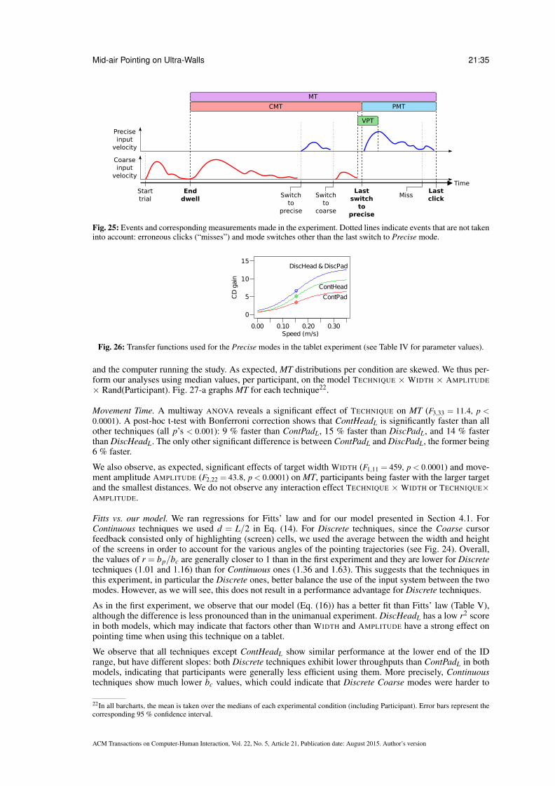
Mid-air Pointing on Ultra-Walls 21:35
Starttrial
Enddwell
Switchto
precise
Lastswitch
toprecise
Switchto
coarse
MissLastclick
MT
CMT PMT
VPT
Time
Coarseinput
velocity
Preciseinput
velocity
Fig. 25: Events and corresponding measurements made in the experiment. Dotted lines indicate events that are not takeninto account: erroneous clicks (“misses”) and mode switches other than the last switch to Precise mode.
0.00 0.10 0.20 0.30Speed (m/s)
CD
gain
DiscHead & DiscPad
ContHead
ContPad
10
5
0
15
Fig. 26: Transfer functions used for the Precise modes in the tablet experiment (see Table IV for parameter values).
and the computer running the study. As expected, MT distributions per condition are skewed. We thus per-form our analyses using median values, per participant, on the model TECHNIQUE × WIDTH × AMPLITUDE
× Rand(Participant). Fig. 27-a graphs MT for each technique22.
Movement Time. A multiway ANOVA reveals a significant effect of TECHNIQUE on MT (F3,33 = 11.4, p <0.0001). A post-hoc t-test with Bonferroni correction shows that ContHeadL is significantly faster than allother techniques (all p’s < 0.001): 9 % faster than ContPadL, 15 % faster than DiscPadL, and 14 % fasterthan DiscHeadL. The only other significant difference is between ContPadL and DiscPadL, the former being6 % faster.
We also observe, as expected, significant effects of target width WIDTH (F1,11 = 459, p < 0.0001) and move-ment amplitude AMPLITUDE (F2,22 = 43.8, p < 0.0001) on MT, participants being faster with the larger targetand the smallest distances. We do not observe any interaction effect TECHNIQUE × WIDTH or TECHNIQUE×AMPLITUDE.
Fitts vs. our model. We ran regressions for Fitts’ law and for our model presented in Section 4.1. ForContinuous techniques we used d = L/2 in Eq. (14). For Discrete techniques, since the Coarse cursorfeedback consisted only of highlighting (screen) cells, we used the average between the width and heightof the screens in order to account for the various angles of the pointing trajectories (see Fig. 24). Overall,the values of r = bp/bc are generally closer to 1 than in the first experiment and they are lower for Discretetechniques (1.01 and 1.16) than for Continuous ones (1.36 and 1.63). This suggests that the techniques inthis experiment, in particular the Discrete ones, better balance the use of the input system between the twomodes. However, as we will see, this does not result in a performance advantage for Discrete techniques.
As in the first experiment, we observe that our model (Eq. (16)) has a better fit than Fitts’ law (Table V),although the difference is less pronounced than in the unimanual experiment. DiscHeadL has a low r2 scorein both models, which may indicate that factors other than WIDTH and AMPLITUDE have a strong effect onpointing time when using this technique on a tablet.
We observe that all techniques except ContHeadL show similar performance at the lower end of the IDrange, but have different slopes: both Discrete techniques exhibit lower throughputs than ContPadL in bothmodels, indicating that participants were generally less efficient using them. More precisely, Continuoustechniques show much lower bc values, which could indicate that Discrete Coarse modes were harder to
22In all barcharts, the mean is taken over the medians of each experimental condition (including Participant). Error bars represent thecorresponding 95 % confidence interval.
ACM Transactions on Computer-Human Interaction, Vol. 22, No. 5, Article 21, Publication date: August 2015. Author’s version
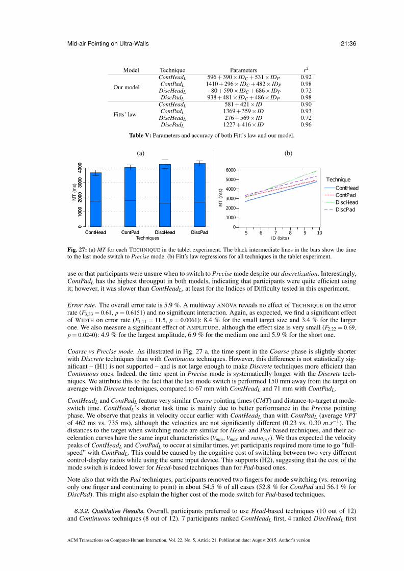
Mid-air Pointing on Ultra-Walls 21:36
Model Technique Parameters r2
Our model
ContHeadL 596+390× IDC +531× IDP 0.92ContPadL 1410+296× IDC +482× IDP 0.98
DiscHeadL −80+590× IDC +686× IDP 0.72DiscPadL 938+481× IDC +486× IDP 0.98
Fitts’ law
ContHeadL 581+421× ID 0.90ContPadL 1369+359× ID 0.93
DiscHeadL 276+569× ID 0.72DiscPadL 1227+416× ID 0.96
Table V: Parameters and accuracy of both Fitt’s law and our model.
(a) (b)
ContHead ContPad DiscHead DiscPad
Techniques
MT
(m
s)
01
00
02
00
03
00
04
00
0
ContHead ContPad DiscHead DiscPad
01
00
02
00
03
00
04
00
0
0
1000
2000
3000
4000
5000
6000
MT (
ms)
5 6 7 8 9 10ID (bits)
Technique
ContHeadContPadDiscHeadDiscPad
Fig. 27: (a) MT for each TECHNIQUE in the tablet experiment. The black intermediate lines in the bars show the timeto the last mode switch to Precise mode. (b) Fitt’s law regressions for all techniques in the tablet experiment.
use or that participants were unsure when to switch to Precise mode despite our discretization. Interestingly,ContPadL has the highest througput in both models, indicating that participants were quite efficient usingit; however, it was slower than ContHeadL, at least for the Indices of Difficulty tested in this experiment.
Error rate. The overall error rate is 5.9 %. A multiway ANOVA reveals no effect of TECHNIQUE on the errorrate (F3,33 = 0.61, p = 0.6151) and no significant interaction. Again, as expected, we find a significant effectof WIDTH on error rate (F1,11 = 11.5, p = 0.0061): 8.4 % for the small target size and 3.4 % for the largerone. We also measure a significant effect of AMPLITUDE, although the effect size is very small (F2,22 = 0.69,p = 0.0240): 4.9 % for the largest amplitude, 6.9 % for the medium one and 5.9 % for the short one.
Coarse vs Precise mode. As illustrated in Fig. 27-a, the time spent in the Coarse phase is slightly shorterwith Discrete techniques than with Continuous techniques. However, this difference is not statistically sig-nificant – (H1) is not supported – and is not large enough to make Discrete techniques more efficient thanContinuous ones. Indeed, the time spent in Precise mode is systematically longer with the Discrete tech-niques. We attribute this to the fact that the last mode switch is performed 150 mm away from the target onaverage with Discrete techniques, compared to 67 mm with ContHeadL and 71 mm with ContPadL.
ContHeadL and ContPadL feature very similar Coarse pointing times (CMT) and distance-to-target at mode-switch time. ContHeadL’s shorter task time is mainly due to better performance in the Precise pointingphase. We observe that peaks in velocity occur earlier with ContHeadL than with ContPadL (average VPTof 462 ms vs. 735 ms), although the velocities are not significantly different (0.23 vs. 0.30 m.s−1). Thedistances to the target when switching mode are similar for Head- and Pad-based techniques, and their ac-celeration curves have the same input characteristics (Vmin, Vmax and ratioin f ). We thus expected the velocitypeaks of ContHeadL and ContPadL to occur at similar times, yet participants required more time to go “full-speed” with ContPadL. This could be caused by the cognitive cost of switching between two very differentcontrol-display ratios while using the same input device. This supports (H2), suggesting that the cost of themode switch is indeed lower for Head-based techniques than for Pad-based ones.
Note also that with the Pad techniques, participants removed two fingers for mode switching (vs. removingonly one finger and continuing to point) in about 54.5 % of all cases (52.8 % for ContPad and 56.1 % forDiscPad). This might also explain the higher cost of the mode switch for Pad-based techniques.
6.3.2. Qualitative Results. Overall, participants preferred to use Head-based techniques (10 out of 12)and Continuous techniques (8 out of 12). 7 participants ranked ContHeadL first, 4 ranked DiscHeadL first
ACM Transactions on Computer-Human Interaction, Vol. 22, No. 5, Article 21, Publication date: August 2015. Author’s version

Mid-air Pointing on Ultra-Walls 21:37
0.00 0.10 0.20 0.30Speed (m/s)
DiscHead&DiscPad
ContHead&ContPad
CDgain 10
5
0
15
Fig. 28: Transfer functions used for the Precise modes in the smartphone experiment (parameters values in Table IV).
and 2 ranked ContPadL first. However, there were no strong complaints about any particular technique,except for one participant who clearly stated that he disliked Discrete techniques.
Several participants complained about the lack of tactile feedback, making it difficult to know when thefingers where leaving the pointing zone. They expressed the need for some sort of physical border, such asthe border of a touchpad on a laptop. Only one participant answered that holding the tablet for 40 minutescaused fatigue when we inquired about this potential issue.
6.4. Smartphone Experiment
This experiment used a smartphone with a resolution of 480× 320 (Apple iPod Touch, 115 g, 11× 6.2×0.8 cm, screen diagonal: 8.9 cm). Participants held the device in landscape orientation. The pointing zoneused the top 480× 166 pixels (75× 26 mm), yielding an input resolution of 6.4 dot/mm. The transferfunctions are shown in Fig. 28.
We took the feedback about the lack of tactile feedback by the participants in the previous experiment intoaccount. We attached a thick tape delimiting the pointing zone (3 mm wide, 0.8 mm thick, see Fig. 31) tothe device. Preliminary tests showed that the tape made it much easier to find the input zone eyes-free andto know in advance when the finger is about to leave the input zone while pointing.
Results are very similar to those of the tablet experiment. We get similar error rates, and an overall subjectivepreference for ContHeadS.
Movement time. The ANOVA reveals a significant effect of TECHNIQUE on MT (F3,33 = 12.1, p < 0.0001) and,as in the first experiment, no interaction of TECHNIQUE with WIDTH, AMPLITUDE and WIDTH × AMPLITUDE.A post-hoc t-test with Bonferonni correction shows that ContHead is significantly faster than all the othertechniques (all p’s < 0.0001), with a speed up of 13 % against ContPad, 12 % against DiscHead and 16 %against DiscPad. Regarding WIDTH and AMPLITUDE we find results similar to the smartphone experimentfor MT. Movement time, split between the coarse and precise phases, is shown in Fig. 29-a using the samescale as in Fig. 27-a.
Fitts’ law vs. our model. We used the same values for d (Eq. (14)) as in the previous experiment. Fitts’ lawfits the data better than in the tablet experiment, though our model (Eq. (28)) still produces higher r2 scores(Table VI).
Model Technique Parameters r2
Our model
ContHeadS 472+403× IDC +547× IDP 0.97ContPadS 969+423× IDC +535× IDP 0.97
DiscHeadS 879+463× IDC +472× IDP 0.97DiscPadS 1428+378× IDC +440× IDP 0.95
Fitts’ law
ContHeadS 464+434× ID 0.95ContPadS 966+437× ID 0.96
DiscHeadS 1162+402× ID 0.94DiscPadS 1702+359× ID 0.91
Table VI: Parameters and accuracy of both Fitt’s law and our model.
The regression lines have relatively similar slopes, much more so than in the tablet experiment. The valuesof r = bp/bc are similar to the tablet experiment: 1.02 and 1.16 for Discrete techniques, 1.26 and 1.36 forContinuous techniques.
ACM Transactions on Computer-Human Interaction, Vol. 22, No. 5, Article 21, Publication date: August 2015. Author’s version

Mid-air Pointing on Ultra-Walls 21:38
(a) (b)
ContHead ContPad DiscHead DiscPad
Techniques
MT
(m
s)
01
00
02
00
03
00
04
00
0
ContHead ContPad DiscHead DiscPad
01
00
02
00
03
00
04
00
0
0
1000
2000
3000
4000
5000
6000
5 6 7 8 9 10ID (bits)
MT (
ms)
Technique
ContHeadContPadDiscHeadDiscPad
Fig. 29: (a) MT for each TECHNIQUE in the smartphone experiment. The black intermediate lines in the bars show thetime to the last mode switch to Precise mode. (b) Fitt’s law regressions for all techniques in the smartphone experiment.
Coarse vs. Precise mode. Regarding the coarse pointing phase, this time we observe a significant effectof TECHNIQUE (F3,33 = 5.39, p = 0.0039). ContHeadS is significantly faster than all other techniques, andDiscPadS and ContHeadS are significantly faster than ContPadS (when considering the Coarse phase only).With the smaller pointing zone used in this experiment, we do observe the hypothesized advantage fordiscrete techniques (H1). However, the time gained during the coarse phase is again not sufficient to makeDiscrete techniques faster than Continuous ones.
Regarding the precise (and post mode-switch) phase, we note that the distance to the target at the lastmode switch is 83 mm and 88 mm for ContHead and ContPad, and 149 mm and 179 mm for DiscHeadand DiscPad. The difference between continuous and discrete techniques shows that the time saved in thecoarse phase by the discrete technique does not lead to better performance for the full pointing task.
In the case of ContHead and ContPad the above distances are very similar, but ContHead is faster thanContPad (even though they use the same transfer function), widening the gap that already exists in theCoarse phase. As in the tablet experiment, it seems that the cost of the mode switch is higher for ContPadthan for ContHead. Indeed, as in the tablet experiment, the velocity peak comes earlier in the precise phasewith ContHead than with ContPad (485 ms vs 773 ms for peaks of 0.33 and 0.29 m.s−1). Therefore, as inthe tablet experiment, (H2) is supported.
6.4.1. Subjective Results. In this experiment 8 participants (out of 12) ranked the ContHead techniquefirst, 3 participants ranked DiscHead first and one participant ranked DiscPad first. This is similar to thetablet experiment, however no participant preferred ContPadS in this experiment while two of them rankedContPadL first in the tablet experiment (where DiscPad was not ranked first). Only one participant (not thesame as in the tablet) found that holding the smartphone during 40 minutes caused fatigue.
Surprisingly, this experiment was considered more tiring by the participants. Despite the smartphone beinglighter and smaller than the tablet, it required a different grip and, unlike the tablet, the body could not beused to support the weight of the device.
6.5. Discussion
The first result of these studies is that beyond the relative differences in performance and user preference,the four techniques that we designed enabled participants to acquire very small targets from a distancerelatively easily, with an average pointing time under 4.5 seconds and average error rate under 6 %. Thisis very encouraging considering the small size of the touch zones (72.5 and 19.5 cm2). These studies alsoshow that leveraging natural head movements yields very good performance. When the orientation of thehead is not available, dividing difficult pointing tasks into two subtasks performed on the same input surfacealso leads to good performance, confirming the findings of our first experiment (Section 5).
6.5.1. Comparing Tablet and Smartphone Input. Since we did not counterbalance the order of pointingzone sizes (all participants performed the tablet experiment first), and since we added tactile feedback usingtape to delimit the zone in the second experiment, we cannot formally compare overall performance acrossthe results of the two experiments. However, we can make four informal observations:
(1) The movement time difference between ContHead and ContPad is larger for the smartphone (13 %)than for the tablet (9 %), which could be due to (i) the additional haptic feedback provided by the tape
ACM Transactions on Computer-Human Interaction, Vol. 22, No. 5, Article 21, Publication date: August 2015. Author’s version

Mid-air Pointing on Ultra-Walls 21:39
surrounding the touch area in the Smartphone experiment and/or (ii) the lower size of the input zonecausing smaller repositioning movements between the Coarse and Precise phases.
(2) ContPadS is not significantly faster than DiscPadS, as opposed to ContPadL vs. DiscPadL. This is partlyexplained by the fact that in the range of Fitts’ IDs that we evaluated, the fitting curves of ContPad andDiscPad tend to diverge in the Tablet experiment and converge in the Smartphone experiment (Fig. 27-band 29-b).
(3) Fig. 27-a and 29-a suggest that DiscHead performed better with the smartphone than with the tablet,relative to ContPad and DiscPad. These observations suggest that as we had anticipated, Head-basedtechniques are at an advantage with smaller pointing zones.
(4) Continuous techniques have higher slopes with the smartphone, as opposed to Discrete techniqueswhich show lower slopes. If this effect holds at higher IDs, e.g. when performing subpixel pointing withlenses, Discrete techniques could outperform Continuous techniques.
6.5.2. Cost of Switching in Discrete Techniques. In Section 5, we hypothesized that participants tended toswitch mode closer to the target than needed when either (1) the Precise phase seemed difficult (small targetsize), or (2) the Coarse phase was short enough (small amplitude) to spend extra time in Coarse mode andswitch to Precise closer to the target. We expected this decision process to be cognitively demanding andtime consuming.
To address this problem we investigated Discrete techniques that simplify the decision by leaving the userlittle or no choice about the switch location. However in both the Tablet and Smartphone experiments theeffect of discretization on Dual-Precision pointing performance was either neutral or negative. This suggeststhat the mode-switching strategy observed in Section 5 is more efficient than forcing the location and timeof the mode switch, at least within the range of IDs that we tested.
We studied only one size for the discretization: the cells corresponded to the screens of our ultra-wall. Futurework will investigate the effect of the size and number of the cells, similar to the theoretical analysis of L inSection 4.1.
7. STUDY 3: POINTER ACCELERATION VS. DUAL-PRECISION TECHNIQUES
0.00 0.10 0.20 0.30Speed (m/s)
RelaLarge
RelaSmall
CDgain
60
20
0
80
40
Fig. 30: Transfer functions used for the third study (see Table VII for parameter values).
In Section 5 we studied the design of unimanual mid-air pointing techniques that can accommodate verydifficult pointing tasks. We explored Dual-Precision techniques, following the calibration methods definedin Section 4.1, and applied the Pointer Acceleration transfer function presented in Section 4.2 to angularmid-air input. In Section 6 we explored the design of Dual-Precision mid-air pointing techniques that usedminimal portions of a touch-screen, either by using head orientation as an additional input channel or byvarying the number of fingers in contact with the touch area. These designs and results provide useful dataon which technique to use depending on the other tasks that must be performed during or after pointing andon the available input devices and channels of a given platform.
We now apply our Pointer Acceleration calibration method to mode-less, touch-based relative pointing, andcompare it with the best techniques of our previous experiments, Laser+Gyro and ContHead, and to onestate-of-the-art baseline technique for mid-air pointing, Smoothed Pointing (SmoothPoint).
7.1. Techniques
We implemented RelaSmall and RelaLarge, two purely relative, trackpad-like techniques that differ onlyin the size of the input area and the transfer function, optimized for this size (Fig. 30). Compared to thefunctions used in the two experiments of Section 6, these two functions feature a much higher CDmax
ACM Transactions on Computer-Human Interaction, Vol. 22, No. 5, Article 21, Publication date: August 2015. Author’s version
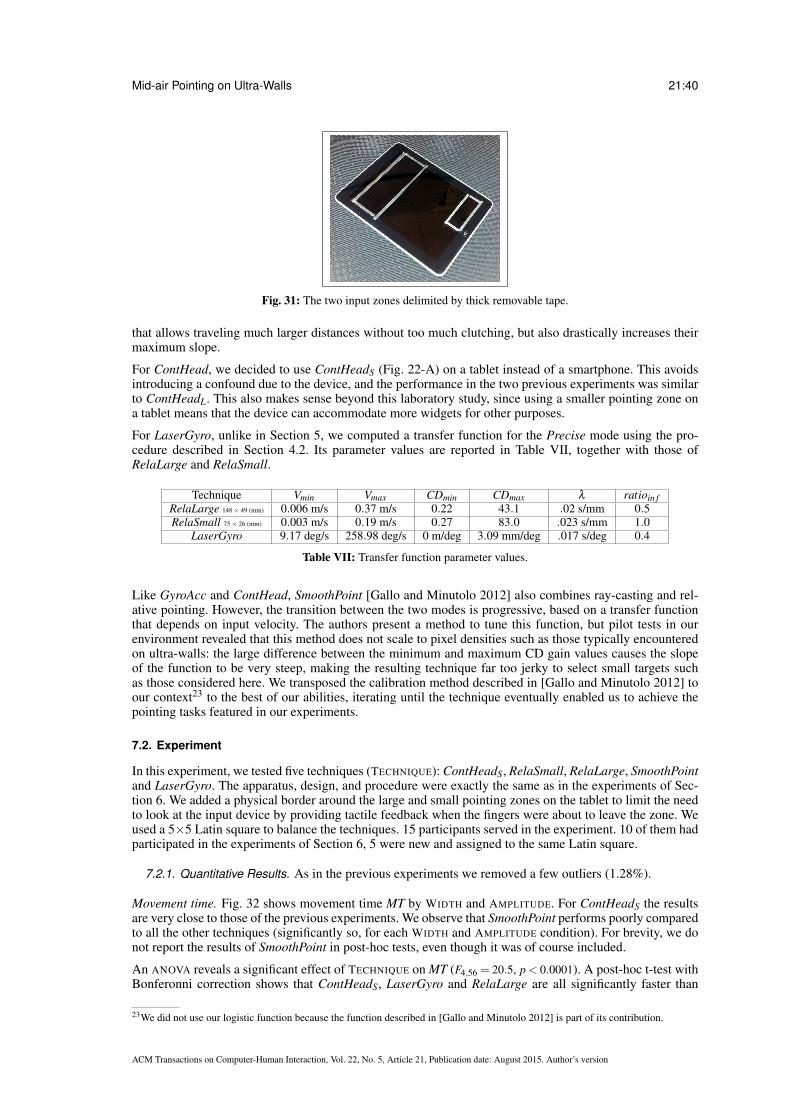
Mid-air Pointing on Ultra-Walls 21:40
Fig. 31: The two input zones delimited by thick removable tape.
that allows traveling much larger distances without too much clutching, but also drastically increases theirmaximum slope.
For ContHead, we decided to use ContHeadS (Fig. 22-A) on a tablet instead of a smartphone. This avoidsintroducing a confound due to the device, and the performance in the two previous experiments was similarto ContHeadL. This also makes sense beyond this laboratory study, since using a smaller pointing zone ona tablet means that the device can accommodate more widgets for other purposes.
For LaserGyro, unlike in Section 5, we computed a transfer function for the Precise mode using the pro-cedure described in Section 4.2. Its parameter values are reported in Table VII, together with those ofRelaLarge and RelaSmall.
Technique Vmin Vmax CDmin CDmax λ ratioin fRelaLarge 148 × 49 (mm) 0.006 m/s 0.37 m/s 0.22 43.1 .02 s/mm 0.5RelaSmall 75 × 26 (mm) 0.003 m/s 0.19 m/s 0.27 83.0 .023 s/mm 1.0
LaserGyro 9.17 deg/s 258.98 deg/s 0 m/deg 3.09 mm/deg .017 s/deg 0.4
Table VII: Transfer function parameter values.
Like GyroAcc and ContHead, SmoothPoint [Gallo and Minutolo 2012] also combines ray-casting and rel-ative pointing. However, the transition between the two modes is progressive, based on a transfer functionthat depends on input velocity. The authors present a method to tune this function, but pilot tests in ourenvironment revealed that this method does not scale to pixel densities such as those typically encounteredon ultra-walls: the large difference between the minimum and maximum CD gain values causes the slopeof the function to be very steep, making the resulting technique far too jerky to select small targets suchas those considered here. We transposed the calibration method described in [Gallo and Minutolo 2012] toour context23 to the best of our abilities, iterating until the technique eventually enabled us to achieve thepointing tasks featured in our experiments.
7.2. Experiment
In this experiment, we tested five techniques (TECHNIQUE): ContHeadS, RelaSmall, RelaLarge, SmoothPointand LaserGyro. The apparatus, design, and procedure were exactly the same as in the experiments of Sec-tion 6. We added a physical border around the large and small pointing zones on the tablet to limit the needto look at the input device by providing tactile feedback when the fingers were about to leave the zone. Weused a 5×5 Latin square to balance the techniques. 15 participants served in the experiment. 10 of them hadparticipated in the experiments of Section 6, 5 were new and assigned to the same Latin square.
7.2.1. Quantitative Results. As in the previous experiments we removed a few outliers (1.28%).
Movement time. Fig. 32 shows movement time MT by WIDTH and AMPLITUDE. For ContHeadS the resultsare very close to those of the previous experiments. We observe that SmoothPoint performs poorly comparedto all the other techniques (significantly so, for each WIDTH and AMPLITUDE condition). For brevity, we donot report the results of SmoothPoint in post-hoc tests, even though it was of course included.
An ANOVA reveals a significant effect of TECHNIQUE on MT (F4,56 = 20.5, p < 0.0001). A post-hoc t-test withBonferonni correction shows that ContHeadS, LaserGyro and RelaLarge are all significantly faster than
23We did not use our logistic function because the function described in [Gallo and Minutolo 2012] is part of its contribution.
ACM Transactions on Computer-Human Interaction, Vol. 22, No. 5, Article 21, Publication date: August 2015. Author’s version

Mid-air Pointing on Ultra-Walls 21:41
Large Small
Width
MT
(m
s)
01
00
03
00
05
00
0
Large Small
01
00
03
00
05
00
0
ContHead LaserGyro RelaLarge RelaSmall Smooth
Small Medium Large
Amplitude
MT
(m
s)
01
00
03
00
05
00
0
Small Medium Large
01
00
03
00
05
00
0
ContHead LaserGyro RelaLarge RelaSmall Smooth
Fig. 32: MT for each TECHNIQUE by WIDTH and by AMPLITUDE for the last experiment.
0
1000
2000
3000
4000
5000
6000
MT (
ms)
5 6 7 8 9 10ID (bits)
Technique
ContHead
Laser+GyroRelative LargeRelative SmallSmoothed
Fig. 33: Fitt’s law regressions for all techniques in the baselines experiment.
RelaSmall (with speed-ups of 5.4%, 8% and 9%, respectively). We find no significant difference betweenContHeadS, LaserGyro and RelaLarge.
This time, the ANOVA reveals significant interactions TECHNIQUE × WIDTH (F4,56 = 5.90, p = 0.0005) andTECHNIQUE× AMPLITUDE (F8,112 = 2.60, p= 0.0122) on MT. One cause for these interactions is SmoothPoint,which is slower for small targets than for larger ones, and faster for the largest amplitude. We also observe(Fig. 32) that the two relative techniques, RelaSmall and RelaLarge, are faster for the small width and thesmall amplitude. Indeed, post-hoc tests show that (i) for small targets, the only significant difference is thatRelaLarge is faster than RelaSmall, and for large targets, ContHeadS and LaserGyro are also significantlyfaster than RelaSmall; (ii) for the small amplitude the only significant difference is that RelaLarge is fasterthan RelaSmall and ContHeadS, while for the large amplitude the only significant difference is that bothRelaLarge and ContHeadS are significantly faster than RelaSmall.
Fitts’ Law vs our model. Table VIII shows the regressions for Fitts’ Law and our model, when applica-ble. We ran our model on SmoothPoint since it uses two pointing modes, even though the switch occursprogressively and implicitly.
Technique Fitts’ law r2 Our model r2
ContHead −177+518× ID 0.88 −68+354× IDC +754× IDP 0.98LaserGyro −342+523× ID 0.95 −310+458× IDC +681× IDP 0.99RelaLarge −234+493× ID 0.99RelaSmall 24+509× ID 0.97
SmoothPoint 122+573× ID 0.8 318+301× IDC +905× IDP 0.98
Table VIII: Parameters and accuracy of both Fitt’s law and our model.
Our model fits data better than Fitts’ law for techniques using two modes, especially ContHead and Smooth-Point. We believe this is because the single slope parameter in Fitts’ law (Eq. (13), p. 12) cannot conveyprecise information about both pointing phases. For example, we observe that ContHead has a throughputtwice as high in Coarse mode than in Precise mode (r = 2.13 in Eq. (18), p. 13) and that using head ori-entation for coarse pointing is more efficient than laser pointing (bC = 354 vs. 458 ms/b for ContHead vs.LaserGyro). We also observe a high throughput in Coarse mode (low bc) for SmoothPoint, indicating thatit is very efficient for coarse pointing; however, as hinted by its low throughput in Precise mode (high bp),it is far too slow to acquire small targets. This corresponds to our own observations: SmoothPoint was veryhard to control at low speeds.
ACM Transactions on Computer-Human Interaction, Vol. 22, No. 5, Article 21, Publication date: August 2015. Author’s version

Mid-air Pointing on Ultra-Walls 21:42
12
34
5
ContHead LaserGyro RelaLarge RelaSmall Smooth
12
34
51
23
45
Preference
Fatigue
Performance
Fig. 34: Preference, fatigue and (self-reported) perceived performance for each TECHNIQUE on a five-point Likert scale(5 is best, 1 is worst). Bold lines show the median, boxes show the lower and upper quartiles and the whiskers show the1.5 × inter-quartile range.
Error rate. The overall error rate is 9.6%. ContHeadS, RelaSmall and RelaLarge feature low error rates(3.90%, 3.52% and 4.04%) with only marginal differences between large and small targets (2.5% vs 5.17%).LaserGyro and SmoothPoint also feature low error rates for large targets (0.70% and 5.60%), but the errorrate rises dramatically for small targets: 25.6% and 43.0%. Based on our pilot studies, we did not expectsuch an increase. The problem comes from the fact that clicking with the handheld wireless mouse causesthe cursor to sometimes leave the target. This led users to click multiple times in quick succession to acquirethe target. However, the high error rate of LaserGyro did not cause a big penalty in pointing time comparedto the touch-based techniques, as opposed to SmoothPoint. SmoothPoint caused twice as many Misses onaverage (mean 0.87, stdev 1.5) as LaserGyro (mean 0.4, stdev 0.75), and 74 % of the errors with LaserGyrowere caused by a single Miss per trial vs. 49 % for SmoothPoint. This suggests that LaserGyro was easierto control with small targets.
7.2.2. Qualitative Results. At the end of the experiment, we asked participants to rank the techniques ona five-point Likert scale in terms of preference, fatigue and perceived performance. Fig. 34 summarizes theresults in a boxplot.
Kruskal-Wallis tests revealed a significant effect of TECHNIQUE on Preference (χ24 = 28.5, p < 0.0001) and
Performance (χ24 = 23.4, p = 0.0001), but not on Fatigue. Post-hoc tests using Mann-Whitney tests with Bon-
ferroni correction show that (i) ContHeadS and LaserGyro were preferred to both RelaSmall and Smooth-Point; (ii) RelaLarge was preferred to SmoothPoint; (iii) ContHeadS, LaserGyro and RelaLarge were per-ceived as faster than SmoothPoint; and (iv) LaserGyro (and ContHeadS) was perceived as (marginally) fasterthan RelaLarge.
7.3. Discussion and Design Guidelines
Overall, the results show that our techniques, designed according to the guidelines introduced in Section 4,fare better than state-of-the-art mid-air pointing techniques and enable users to perform pointing tasks withhigh a high Index of Difficulty. More precisely, the three techniques that perform best in terms of movementtime and preference are RelaLarge, ContHead and LaserGyro. While there is no significant difference inmovement time among them, each technique has its own strengths and limitations, making it more suitableto specific contexts of use.
While relative pointing is not novel, making it work efficiently in such challenging contexts is an interestingresult. Indeed, existing functions, even elaborate ones such as that of SmoothPoint, were designed for lower-resolution environments, and fare poorly with the high Fitts’ IDs considered here. We suspect that this isbecause SmoothPoint uses a sine-based function that does not allow control of the abscissa and slope ofits inflexion point: for a given input and output range, the method provides a single function that can bevery steep when the output range is much larger than the input range. Indeed, the cursor was much jerkierwith SmoothPoint than with any other technique evaluated in this study. RelaLarge, based on the transferfunction and calibration method introduced in Section 4.2, provides pointing performance that matches thatof more elaborate techniques. It is straightforward to implement and does not require special equipment totrack the 3D position and orientation of the device or user.
RelaSmall provides enough precision to perform bivariate pointing tasks of difficulty up to 9.5 bits with apointing zone of 20 cm2 only (approximately 1/4th of RelaLarge’s surface area). We did not expect suchgood performance. Given that the size of the pointing zone of RelaLarge preclude its use on smartphones,
ACM Transactions on Computer-Human Interaction, Vol. 22, No. 5, Article 21, Publication date: August 2015. Author’s version

Mid-air Pointing on Ultra-Walls 21:43
RelaSmall can be an appealing option. Indeed, the technique will only incur a 5-to-10-percent performancecost when compared to more efficient techniques, which can be considered an acceptable tradeoff whenonly small handheld devices are available, or when a large portion of the handheld’s screen real-estate mustbe allocated to additional interface widgets.
This decrease in performance can be avoided by using ContHead, which achieves the same level of perfor-mance as RelaLarge but on a much smaller input area, equivalent to that of RelaSmall. ContHead shouldbe considered when the task and context of use require many additional interface widgets or when onlysmartphones are available, provided that tracking the location and orientation of the head is possible.
0.0
1.0
2.0
3.0
0 100 200 300V (deg/s)input
CD
gain
(m
m/d
eg
) Baselinesexperiment
One-handedexperiment
Fig. 35: Transfer functions used for the Precise mode of LaserGyro in the unimanual experiment (dashed) and in thebaselines experiment (plain blue). The blue circle represents the inflexion point of the transfer function.
Finally, our implementation of LaserGyro causes many more errors than the other techniques for smallvalues of WIDTH, because the tremor caused by pressing a physical button is sufficient to miss small targetsgiven the current transfer function. LaserGyro did not cause that many errors in the unimanual experiment(Section 5) because we used a low constant CD gain (.89 mm/deg) compared to the range used in thebaselines experiment (mean 1.9 mm/deg in the [Vmin,Vmax] interval, Fig. 35). This raises the question ofwhether the calibration of the transfer function used in Precise mode should also be adapted to the type ofinput device and to the clicking mechanism, for exemple by setting PSdevice to the amplitude of the cursormovement corresponding to the aforementioned tremor in Equations (9), (20) and (22). For touch-basedtechniques, using a tap for clicking did not affect the cursor location.
8. IMPLICATIONS FOR DESIGN
In this work we started to map the design space of pointing techniques for ultra-walls. We studied twocategories of techniques: Pointer Acceleration (PA) and Dual-Precision (DP). Tables IX and X describe thesubset of the design space that we explored in terms of the input dimensions that were sensed and theirmapping to cursor movements. For Dual-Precision techniques, we also list the transition mechanism.
Study Technique Input Mapping1 GyroAcc Relative arm rotation Variable gain
RelaSmall Relative touch (small area) Variable gain3 RelaLarge Relative touch (large area) Variable gain
SmoothPoint Ray-casting (arm) Direct + Variable gain
Table IX: Design space of Pointing Acceleration techniques (see text for explanations).
Study Technique Coarse Coarse Transition Precise Preciseinput mapping input mapping
LaserGyro (1) Ray-casting (arm) Direct Button Rel. arm rotation Constant gain1 Laser+Position Ray-casting (arm) Direct Button Rel. arm translation Constant gain
Laser+Track Ray-casting (arm) Direct Touch Rel. touch Constant gain
2
ContHeadL Abs. head rotation Direct24 Touch Rel. touch (large area) Variable gainContHeadS Abs. head rotation Direct24 Touch Rel. touch (small area) Variable gainContPadL Abs. touch (large area) Indirect #fingers Rel. touch (large area) Variable gainContPadS Abs. touch (small area) Indirect #fingers Rel. touch (small area) Variable gain
3 LaserGyro (3) Ray-casting (arm) Direct Button Rel. arm rotation Variable gain
Table X: Design space of Dual Precision techniques (Abs. stands for Absolute, Rel. for Relative - see text for additionalexplanations). The precise mapping of LaserGyro changed between studies (1) and (3).
24The Coarse mode of the -Head techniques is a linear mapping between absolute orientation input and absolute cursor location,therefore not strictly a direct mapping (see Section 6.1.2 p. 29). However, we tuned it so that it was perceived as one.
ACM Transactions on Computer-Human Interaction, Vol. 22, No. 5, Article 21, Publication date: August 2015. Author’s version

Mid-air Pointing on Ultra-Walls 21:44
When input is absolute, the mapping can be either Direct, when pointing at the real target, or Indirect, whenpointing on a separate surface such as a handheld tablet. When input is relative, the mapping is specifiedby the type of gain applied to the sensed motion: Constant or Variable. Ray-casting requires both absoluteposition and rotation sensing of the hand. SmoothPoint is a special case that applies a variable CD-gain toabsolute ray-casting input in its precision mode.
Generally speaking, sensing an absolute dimension (absolute input) is more demanding than sensing itschanges (relative input). For example, tracking the mid-air position and orientation of the arm and handtypically requires an external motion tracking system while tracking the variations of its position and orien-tation can be done with an accelerometer held in the hand or attached to the arm.
The rest of this section builds on this design space and on the results of our studies to provide guidelines onhow to choose a mid-air pointing technique given the input capabilities of the interactive platform (e.g. withor without motion tracking) and the interaction requirements of its users (e.g. tablet-based interactions).We then discuss two high-level psycho-motor factors that seem to affect the usability and performance ofpointing techniques and that can suggest new directions to design more efficient pointing techniques.
8.1. Choosing among pointing techniques
Input requirementsSubjectiveevaluation
Study Technique Type Involved limbsToucharea
Angularsensing
Positionsensing Ranking
1
LaserGyro DP 1 hand n/a Absolute Absolute 1/4Laser+Position DP 1 hand n/a Absolute Absolute 2/4
GyroAcc PA 1 hand n/a Relative n/a 3/4Laser+Track DP 1 hand Small Absolute Absolute 3.5/4
2
ContHeadL DP 2 hands + head Large Absolute Absolute 1/4ContHeadS DP 2 hands + head Small Absolute Absolute 1/4ContPadL DP 2 hands Large n/a n/a 3/4ContPadS DP 2 hands Small n/a n/a 3/4
3
LaserGyro DP 1 hand n/a Absolute Absolute 2/5ContHeadS DP 2 hands + head Small Absolute Absolute 2/5RelaLarge PA 2 hands Large n/a n/a 3/5RelaSmall PA 2 hands Small n/a n/a 4/5
SmoothPoint PA 1 hand n/a Absolute Absolute 4/5
Table XI: Main input requirements and subjective ranking of the techniques evaluated in Sections 5, 6 and 7. DP standsfor Dual-Precision, PA for Pointer Acceleration. Angular and Position sensing are the input requirements to capture theangle and position of the limbs. Ranking is the median preference score of the technique in the experiment (1 is best).
Beyond their relative performance ranking, all the techniques that we designed enabled users to select verysmall targets at a distance with good performance, i.e. less than 5 seconds for most techniques, with differentinput requirements. Table XI summarizes these input requirements and Fig. 36 summarizes performanceresults. For movement time, we show the Fitts’ law regressions25. For error rate, since in most cases targetwidth had a significant effect on error rate (as opposed to the Fitts’ ID or amplitude), we represent errorrates for each target width.
Using these tables, interaction designers can select a technique depending on the input requirements ofthe task and the input capabilities of the platform, as well as the maximum pointing difficulty and userpreferences. For example, in situations without absolute real-time motion tracking, GyroAcc can be used foreasier tasks (ID < 8 bits, WIDTH> 15 mm) and provide good performance while leaving one hand free forother interactions performed with another device; RelaSmall is the only technique allowing precise pointingon a small touch sensitive surface without absolute motion tracking; for wide ranges of IDs, LaserGyro andContHead provide the best performance and user preference overall, but require absolute motion tracking;finally, despite its lower performance, Laser+Track is the only technique allowing unimanual interactionand additional touch-based input.
25As noted earlier, we may have obtained better fits with angle-based models [Kopper et al. 2010; Jota et al. 2010] for angular-basedpointing techniques (SmoothPoint, GyroAcc) and modes (Laser- and -Head techniques). However, this would have prevented us fromcomparing these techniques to the other ones based on a common definition of task difficulty.
ACM Transactions on Computer-Human Interaction, Vol. 22, No. 5, Article 21, Publication date: August 2015. Author’s version

Mid-air Pointing on Ultra-Walls 21:45
One hand Two handsMedium touch area Small touch area
1000
2000
3000
4000
5000
6000
4 6 8 100
ID (bits)
MT (
ms)
0
1000
2000
3000
4000
5000
6000
MT (
ms)
5 6 7 8 9 10ID (bits)
0
1000
2000
3000
4000
5000
6000
5 6 7 8 9 10ID (bits)
MT (
ms)
4 10 20 30
0.1
0.2
0.3
0.4
0.5
0.6
0
W (mm)
Err
or
rate
0.1
0.2
0.3
0.4
0.5
0.6
04 18
W (mm)
Err
or
rate
0
0.1
0.2
0.3
0.4
4 18W (mm)
Err
or
rate
0.5
0.6
GyroAcc
LaserTrack SmoothPoint
LaserGyro Relative LargeRelative SmallContPad
ContHead
Fig. 36: Fitts’ law regressions and error rates per target widths for our techniques, organized by input requirements.Laser+Position was discarded because of its similarity with Laser+Gyro; we only represent LaserGyro in the firststudy due to its low precision in the last one; SmoothPoint was added for comparison.
8.2. Psycho-motor aspects of high-performance pointing: Decision and Adaptation
The results of the experiments reported in Sections 5, 6 and 7 highlight two cognitive behaviors induced bythe changing transfer function during pointing: Decision and Adaptation.
Decision is the cognitive cost incurred by explicitly breaking the continuity of a pointing task, e.g. whenswitching to a different transfer function. It occurs when users have to decide whether, when and whereto switch transfer function for a given pointing task (defined by its width and amplitude) and pointingtechnique.
For example, we observed in Section 5 that when using a Dual-Precision technique, the width and amplitudeof the pointing task had an effect on the duration of its Coarse phase and on the distance of the mode switchto the target. In some of the easier conditions, participants even tried to select the target in Coarse modeonly, without switching mode.
Our hypothesis, introduced in Section 5, is that the process of deciding where and when to switch modes waspart of a higher-level, subconscious process of optimizing time and effort. Participants took more time andwere more careful about the location of the mode switch (i) when the Coarse phase seemed easy, “saving”time that could be used to ease the Precise phase, or (ii) when the Precise phase seemed difficult, i.e. whenthe target was small: more time was spent in Coarse mode to lower the amplitude of the Precise phase.The no-switch behavior is an extreme case of this optimization process, in which the Coarse mode is ableto bring the cursor so close to the target that the time needed to switch modes and then acquire the targetwith the slower Precise mode might appear greater than the time needed to acquire the target with the lessprecise Coarse mode.
Similar effects have been observed in previous studies. For example, [Mandryk and Lough 2011] studiedthe effect of the intended use of the target on the performance of pointing tasks with the same Fitts’ ID.The task consisted of acquiring a target, then performing a second subtask that could be either click, clickand acquire a second target, press and “throw” the target towards an edge of the screen, or drag the targetonto another target. The authors observed that the changes in movement time could be attributed to thedifferences in the secondary, precise pointing phase, and not the initial ballistic phase. In accordance withour results, the authors hypothesize that the movement time increases with the precision of the objective,and that motor planning and control of the second subtask is encapsulated within the second phase ofthe first subtask. [Quinn et al. 2011] observed a similar effect when studying multiple trajectory pointing
ACM Transactions on Computer-Human Interaction, Vol. 22, No. 5, Article 21, Publication date: August 2015. Author’s version

Mid-air Pointing on Ultra-Walls 21:46
methods. Participants did not always perform better with methods that shorten the trajectory to a target,such as cursor wrapping [Huot et al. 2011] or Ninja cursors [Kobayashi and Igarashi 2008]. The authorssuggest that selecting the best trajectory among several possibilities caused search and decision times thateventually cancelled out the potential performance advantage.
Adaptation is the cognitive and motor adjustment to a change in transfer function. It occurs after a suddenchange that requires the user to adapt to a transfer function whose parameters are significantly differentfrom that of the previous one. This change can be due to a change of input, e.g. switching between twoinput devices or modes to control cursor displacements, or a change of control, e.g. transitioning betweenvery different CD gains.
From our experimental results we hypothesize three possible causes of Adaptation:
(1) Steeper slopes in transfer functions require more cognitive and motor adjustments between their lowerand higher levels – We observed in Section 7 that steeper slopes lead to poorer performance. Indeed,SmoothPoint was the worst technique for all measures, followed by RelaSmall for movement time.
(2) Different transfer functions are better controlled with different limbs – When controlled with one hand,switching from one transfer function to another constrains the starting point of the latter to the last pointof the former. Users thus have a limited operating range and must adapt their body movements accord-ingly, e.g. by clutching. In the Tablet experiment in Section 6, participants spent more time in Precisemode with the Pad-based techniques than with the Head-based techniques, despite the morphologicalsimilarity between the Coarse and Precise control of the Pad-based techniques. In both experiments ofthat section, participants also took more time to reach their peak velocity in Precise mode with ContHeadthan with ContPad, despite the similar proximity of the cursor to the target at mode-switch time.
(3) When controlled with the same limb, different transfer functions are better controlled with similar inputchannels – For example, switching from angular to linear control is more cognitively demanding than ifthe whole pointing movement is angular or linear. We observed in Section 5 that users spent less timein Precise mode with Laser+Gyro than with Laser+Position and Laser+Track, even though the averageamplitudes of the Precise sub-task were not significantly different. Indeed, angular control (Precise modeof Laser+Gyro) is morphologically closer to ray-casting (Coarse mode of all three techniques) than mid-air position control and touch input (Precise modes of Laser+Position and Laser+Track respectively).
The controlled experiments in Sections 5, 6 and 7 were intended to evaluate the performance and the mor-phological aspects of input techniques, not to investigate cognition and dynamic motor control. Future workis needed to assess these hypotheses.
9. CONCLUSION
In this paper we investigated pointing techniques for location-independent interaction on ultra-walls. Theseenvironments enable very large datasets to be visualized and manipulated by several users simultaneously.Their large physical size and high pixel density create new constraints for interaction: users may need toacquire very small targets from relatively far away, and other interactions must remain possible with theinput devices at hand.
In Section 3, we explored the limits of existing pointing techniques and devices relative to the output capabil-ities of ultra-walls. We used Casiez et al.’s formulae to develop a theoretical framework for techniques withconstant CD gain [Casiez et al. 2008]. As discussed in Section 3.2, the core problem of constant CD gaintechniques is that the input expressiveness of either the device or user movements fails to match the range ofpointing task difficulty (Eq. (11), p. 8). Pointing techniques therefore need to vary their CD gain, as demon-strated by the improved performance of Pointer Acceleration. In Section 4.1, we described Dual-Precisiontechniques, a family of techniques that provide two modes, each with a specific range of CD gains, forcoarse and precise control. Switching between these modes requires an explicit action so that users canfully control the cursor movements, as opposed to Pointer Acceleration where this transition is implicit.We provided a theoretical analysis of such techniques as well as a method to calibrate the CD gain of eachmode. We also developed a new method for calibrating the transfer functions of Pointer Acceleration tech-niques, based on the capabilities of both the user and the input device(s) as well as the characteristics of thepointing task.
In Sections 5, 6 and 7, we evaluated this framework by designing and implementing a number of mid-airpointing techniques with different gain-variation methods. These techniques were designed to perform verydifficult pointing tasks with limited input requirements such as unimanual pointing or limited size of touchinput area, which are common for mid-air interaction with large displays. Through a series of controlledexperiments we showed that our techniques and their calibration methods meet these goals. Dual-Precision
ACM Transactions on Computer-Human Interaction, Vol. 22, No. 5, Article 21, Publication date: August 2015. Author’s version

Mid-air Pointing on Ultra-Walls 21:47
techniques were always among the fastest techniques in all our studies and were generally preferred byparticipants. Our Pointing Acceleration transfer functions showed similar performance to Dual-Precisiontechniques, and tended to perform better for the easiest tasks, probably because of the constant mode-switchtime and associated cognitive load of Dual-Precision techniques.
Rather than designating one technique as the “best” one, we provide a classification of these techniquesaccording to their performance, input requirements and user preference in order for interaction designersto more easily select the one that best fits their needs. While the techniques introduced in this work canalready be used in a variety of situations, our theoretical framework and the guidelines that we drew fromthe experimental results can be used by other researchers and interaction designers to design new pointingtechniques adapted to their needs. Finally, from our analyses and studies, we gathered general insights aboutthe sensorimotor aspects of highly-varying CD gains, which we summarized and discussed in Section 8.2.
Future work includes a more systematic validation of the models that we developed in Sections 3.2 and 4.1,and of the calibration methods presented in Sections 4.1 and 4.2. In particular, we will investigate how tobetter take clutching into account in the calibration of the transfer functions, taking into account the factthat the resulting increase in CD-gain range can counterbalance the additional time spent clutching [Nancelet al. 2015]. We will also evaluate our hypotheses on the effects of the Decision and Adaptation factorspresented in Section 8.2, and on how they affect the design space of pointing techniques.
REFERENCES
Jonathan Aceituno, Gery Casiez, and Nicolas Roussel. 2013. How low can you go?: Human limits in small unidirectional mousemovements. In Proceedings of the SIGCHI Conference on Human Factors in Computing Systems (CHI ’13). ACM, 1383–1386.DOI:http://dx.doi.org/10.1145/2470654.2466182 5, 16
Hirotugu Akaike. 1974. A new look at the statistical model identification. IEEE Trans. Automat. Control 19, 6 (1974), 716 – 723.DOI:http://dx.doi.org/10.1109/TAC.1974.1100705 25
Christopher Andrews, Alex Endert, and Chris North. 2010. Space to think: large high-resolution displays for sensemaking.In Proceedings of the 28th international conference on Human factors in computing systems (CHI ’10). ACM, 55–64.DOI:http://dx.doi.org/10.1145/1753326.1753336 1
Caroline Appert, Olivier Chapuis, and Michel Beaudouin-Lafon. 2008. Evaluation of pointing performance on screenedges. In Proceedings of the working conference on Advanced Visual Interfaces (AVI ’08). ACM, 119–126.DOI:http://dx.doi.org/10.1145/1385569.1385590 21
Caroline Appert, Olivier Chapuis, and Emmanuel Pietriga. 2010. High-precision magnification lenses. In Proceed-ings of the 28th international conference on Human factors in computing systems (CHI ’10). ACM, 273–282.DOI:http://dx.doi.org/10.1145/1753326.1753366 8
Mark Ashdown, Kenji Oka, and Yoichi Sato. 2005. Combining head tracking and mouse input for a GUI on mul-tiple monitors. In Extended abstracts on Human factors in computing systems (CHI EA ’05). ACM, 1188–1191.DOI:http://dx.doi.org/10.1145/1056808.1056873 30
Robert Ball, Chris North, and Doug Bowman. 2007. Move to improve: promoting physical navigation to increase user performancewith large displays. In Proceedings of the SIGCHI conference on Human factors in computing systems (CHI ’07). ACM, 191–200.DOI:http://dx.doi.org/10.1145/1753326.1753336 1, 6
Patrick Baudisch, Mike Sinclair, and Andrew Wilson. 2006. Soap: a pointing device that works in mid-air. In Proceed-ings of the 19th annual ACM symposium on User interface software and technology (UIST ’06). ACM, 43–46.DOI:http://dx.doi.org/10.1145/1166253.1166261 9
Michel Beaudouin-Lafon, Olivier Chapuis, James Eagan, Tony Gjerlufsen, Stephane Huot, Clemens Klokmose, Wendy Mackay, Math-ieu Nancel, Emmanuel Pietriga, Clement Pillias, Romain Primet, and Julie Wagner. 2012. Multi-surface interaction in the WILDroom. IEEE Computer 45, 4 (2012), 48–56. DOI:http://dx.doi.org/10.1109/MC.2012.110 1, 5, 21
Michel Beaudouin-Lafon, Stephane Huot, Halla Olafsdottir, and Pierre Dragicevic. 2014. GlideCursor: Pointing with aninertial cursor. In Proceedings of the working conference on Advanced Visual Interfaces (AVI ’14). ACM, 49–56.DOI:http://dx.doi.org/10.1145/2598153.2598166 7
Renaud Blanch and Michael Ortega. 2009. Rake cursor: improving pointing performance with concurrent input channels. InProceedings of the 27th international conference on Human factors in computing systems (CHI ’09). ACM, 1415–1418.DOI:http://dx.doi.org/10.1145/1518701.1518914 31
Sebastian Boring, Dominikus Baur, Andreas Butz, Sean Gustafson, and Patrick Baudisch. 2010. Touch projector: mobile interactionthrough video. In Proceedings of the 28th international conference on Human factors in computing systems (CHI ’10). ACM,2287–2296. DOI:http://dx.doi.org/10.1145/1753326.1753671 4
William Buxton, George Fitzmaurice, Ravin Balakrishnan, and Gordon Kurtenbach. 2000. Large displays in automotive design. IEEEComputer Graphics and Applications 20, 4 (2000), 68–75. DOI:http://dx.doi.org/10.1109/38.851753 6
Bryan A. Campbell, Katharine R. O’Brien, Michael D. Byrne, and Benjamin J. Bachman. 2008. Fitts’ law predictions with an al-ternative pointing device (wiimote R©). Human Factors and Ergonomics Society Annual Meeting Proceedings 52, 19 (2008),1321–1325. DOI:http://dx.doi.org/10.1177/154193120805201904 3, 4
Xiang Cao and Ravin Balakrishnan. 2003. Visionwand: interaction techniques for large displays using a passive wand tracked in 3D.In Proceedings of the 16th annual ACM symposium on User interface software and technology (UIST ’03). ACM, 173–182.DOI:http://dx.doi.org/10.1145/964696.964716 4
Gery Casiez and Nicolas Roussel. 2011. No more bricolage!: methods and tools to characterize, replicate and compare pointingtransfer functions. In Proceedings of the 24th annual ACM symposium on User interface software and technology (UIST ’11).ACM, 603–614. DOI:http://dx.doi.org/10.1145/2047196.2047276 2, 4, 7, 11, 15
ACM Transactions on Computer-Human Interaction, Vol. 22, No. 5, Article 21, Publication date: August 2015. Author’s version
Mid-air Pointing on Ultra-Walls 21:48
Gery Casiez and Daniel Vogel. 2008. The effect of spring stiffness and control gain with an elastic rate control pointing de-vice. In Proceedings of the SIGCHI conference on Human factors in computing systems (CHI ’08). ACM, 1709–1718.DOI:http://dx.doi.org/10.1145/1357054.1357321 3
Gery Casiez, Daniel Vogel, Ravin Balakrishnan, and Andy Cockburn. 2008. The impact of control-display gain on user performancein pointing tasks. Human-Computer Interaction 23, 3 (2008), 215–250. DOI:http://dx.doi.org/10.1080/07370020802278163 7,13, 15, 21, 46
Olivier Chapuis, Anastasia Bezerianos, and Stelios Frantzeskakis. 2014. Smarties: An input system for wall display development.In Proceedings of the 32nd international conference on Human factors in computing systems (CHI ’14). ACM, 2763–2772.DOI:http://dx.doi.org/10.1145/2556288.2556956 5, 18
Xing Chen and James Davis. 2000. Lumipoint: Multi-user laser-based interaction on large tiled displays. Displays 23, 5 (2000), 205–211. DOI:http://dx.doi.org/10.1016/S0141-9382(02)00039-2 3
Andy Cockburn, Philip Quinn, Carl Gutwin, and Stephen Fitchett. 2012. Improving scrolling devices with document length depen-dent gain. In Proceedings of the SIGCHI Conference on Human Factors in Computing Systems (CHI ’12). ACM, 267–276.DOI:http://dx.doi.org/10.1145/2207676.2207714 15
Henrique Debarba, Luciana Nedel, and Anderson Maciel. 2012. Lop-cursor: Fast and precise interaction with tiled displaysusing one hand and levels of precision. In IEEE Symposium on 3D User Interfaces (3DUI ’12). IEEE, 125 –132.DOI:http://dx.doi.org/10.1109/3DUI.2012.6184196 20
Paul M. Fitts. 1954. The information capacity of the human motor system in controlling the amplitude of movement. Journal ofExperimental Psychology 47 (1954), 381–391. DOI:http://dx.doi.org/10.1037/h0055392 21
Clifton Forlines, Daniel Vogel, and Ravin Balakrishnan. 2006. Hybridpointing: fluid switching between absolute and relative pointingwith a direct input device. In Proceedings of the 19th annual ACM symposium on User interface software and technology (UIST’06). ACM, 211–220. DOI:http://dx.doi.org/10.1145/1166253.1166286 4, 11
Edward G. Freedman and David L. Sparks. 2000. Coordination of the eyes and head: movement kinematics. Experimental BrainResearch 131, 1 (2000), 22–32. DOI:http://dx.doi.org/10.1007/s002219900296 29, 30
Scott Frees, G. Drew Kessler, and Edwin Kay. 2007. Prism interaction for enhancing control in immersive virtual environments. ACMTransactions on Computer-Human Interaction 14, 1 (2007), 2. DOI:http://dx.doi.org/10.1145/1229855.1229857 4, 15
Luigi Gallo and Aniello Minutolo. 2012. Design and comparative evaluation of smoothed pointing: A velocity-orientedremote pointing enhancement technique. International Journal of Human Computer Studies 70, 4 (2012), 287–300.DOI:http://dx.doi.org/10.1016/j.ijhcs.2011.12.001 4, 9, 11, 12, 15, 19, 40
Yves Guiard and Michel Beaudouin-Lafon. 2004. Target acquisition in multiscale electronic worlds. International Journal of HumanComputer Studies 61, 6 (2004), 875–905. http://dx.doi.org/10.1016/j.ijhcs.2004.09.005 21
Yves Guiard, Frederic Bourgeois, Denis Mottet, and Michel Beaudouin-Lafon. 2001. Beyond the 10-bit barrier: Fitts’ law in multi-scale electronic worlds. In People and Computers XV - Interaction without frontiers (Joint proceedings of HCI 2001 and IHM2001). Springer Verlag, 573–587. DOI:http://dx.doi.org/10.1007/978-1-4471-0353-0 36 21
Francois Guimbretiere, Maureen Stone, and Terry Winograd. 2001. Fluid interaction with high-resolution wall-size displays. InProceedings of the 14th annual ACM symposium on User interface software and technology (UIST ’01). ACM, 21–30.DOI:http://dx.doi.org/10.1145/502348.502353 6
Faizan Haque, Mathieu Nancel, and Daniel Vogel. 2015. Myopoint: Pointing and clicking using forearm mounted electromyographyand inertial motion sensors. In Proceedings of the 33rd Annual ACM Conference on Human Factors in Computing Systems (CHI’15). ACM, 3653–3656. DOI:http://dx.doi.org/10.1145/2702123.2702133 18
Stephane Huot, Olivier Chapuis, and Pierre Dragicevic. 2011. Torusdesktop: pointing via the backdoor is sometimes shorter.In Proceedings of the SIGCHI conference on Human factors in computing systems (CHI ’11). ACM, 829–838.DOI:http://dx.doi.org/10.1145/1978942.1979064 46
Robert Jacob. 1991. The use of eye movements in human-computer interaction techniques: what you look at is what you get. ACMTransactions on Information Systems 9, 2 (1991), 152–169. DOI:http://dx.doi.org/10.1145/123078.128728 30
Mikkel R. Jakobsen and Kasper Hornbæk. 2014. Up close and personal: Collaborative work on a high-resolutionmultitouch wall display. ACM Transactions on Computer-Human Interaction 21, 2, Article 11 (2014), 34 pages.DOI:http://dx.doi.org/10.1145/2576099 1, 2
Herbert D. Jellinek and Stuart K. Card. 1990. Powermice and user performance. In Proceedings of the SIGCHI Conference on HumanFactors in Computing Systems (CHI ’90). ACM, 213–220. DOI:http://dx.doi.org/10.1145/97243.97276 4, 7, 10, 11
Ricardo Jota, Miguel A. Nacenta, Joaquim A. Jorge, Sheelagh Carpendale, and Saul Greenberg. 2010. A comparison of ray pointingtechniques for very large displays. In Proceedings of Graphics Interface (GI ’10). CIPS, 269–276. http://dl.acm.org/citation.cfm?id=1839214.1839261 3, 11, 44
Paul Kabbash and William A. S. Buxton. 1995. The “prince” technique: Fitts’ law and selection using area cursors. In Pro-ceedings of the SIGCHI conference on Human factors in computing systems (CHI ’95). ACM & Addison-Wesley, 273–279.DOI:http://dx.doi.org/10.1145/223904.223939 12
Kenrick Kin, Tom Miller, Bjorn Bollensdorff, Tony DeRose, Bjorn Hartmann, and Maneesh Agrawala. 2011. Eden: a professionalmultitouch tool for constructing virtual organic environments. In Proceedings of the SIGCHI conference on Human factors incomputing systems (CHI ’11). ACM, 1343–1352. DOI:http://dx.doi.org/10.1145/1978942.1979141 29
Kotaro Kitajima, Yoichi Sato, and Hideki Koike. 2001. Vision-based face tracking system for window interface: prototype appli-cation and empirical studies. In Extended Abstracts on Human factors in computing systems (CHI EA ’01). ACM, 359–360.DOI:http://dx.doi.org/10.1145/634067.634279 29, 30
Masatomo Kobayashi and Takeo Igarashi. 2008. Ninja cursors: using multiple cursors to assist target acquisition on largescreens. In Proceedings of the SIGCHI conference on Human factors in computing systems (CHI ’08). ACM, 949–958.DOI:http://dx.doi.org/10.1145/1357054.1357201 46
David R. Kollerl, Mark R. Mine, and Scott E. Hudson. 1996. Head-tracked orbital viewing: an interaction technique for immersivevirtual environments. In Proceedings of the 9th annual ACM symposium on User interface software and technology (UIST ’96).ACM, 81–82. DOI:http://dx.doi.org/10.1145/237091.237103 30
ACM Transactions on Computer-Human Interaction, Vol. 22, No. 5, Article 21, Publication date: August 2015. Author’s version
Mid-air Pointing on Ultra-Walls 21:49
Werner A. Konig, Jens Gerken, Stefan Dierdorf, and Harald Reiterer. 2009. Adaptive pointing: implicit gain adaptation for ab-solute pointing devices. In Extended abstracts on Human factors in computing systems (CHI EA ’09). ACM, 4171–4176.DOI:http://dx.doi.org/10.1145/1520340.1520635 4, 15
Regis Kopper, Doug A. Bowman, Mara G. Silva, and Ryan P. McMahan. 2010. A human motor behavior model for distal pointing tasks.International Journal of Human Computer Studies 68, 10 (2010), 603–615. DOI:http://dx.doi.org/10.1016/j.ijhcs.2010.05.0013, 11, 19, 44
Regis Kopper, Mara G. Silva, Ryan P. McMahan, and Doug A. Bowman. 2008. Increasing the precision of distant pointing for largehigh-resolution displays. In Technical Report TR-08-17, Computer Science, Virginia Tech (2008-01-01). 19
Can Liu, Olivier Chapuis, Michel Beaudouin-Lafon, Eric Lecolinet, and Wendy Mackay. 2014. Effects of display size and navigationtype on a classification task. In Proceedings of the 32nd international conference on Human factors in computing systems (CHI’14). ACM, 4147–4156. DOI:http://dx.doi.org/10.1145/2556288.2557020 1, 6
Scott MacKenzie and Shaidah Jusoh. 2001. An evaluation of two input devices for remote pointing. In Proceedings ofthe 8th IFIP International Conference on Engineering for Human-Computer Interaction (EHCI ’01). Springer, 235–250.DOI:http://dx.doi.org/10.1007/3-540-45348-2 21 3
Shahzad Malik, Abhishek Ranjan, and Ravin Balakrishnan. 2005. Interacting with large displays from a distance with vision-trackedmulti-finger gestural input. In Proceedings of the 18th annual ACM symposium on User interface software and technology (UIST’05). ACM, 43–52. DOI:http://dx.doi.org/10.1145/1095034.1095042 6
Regan L. Mandryk and Calvin Lough. 2011. The effects of intended use on target acquisition. In Proceedings of the SIGCHI conferenceon Human factors in computing systems (CHI ’11). ACM, 1649–1652. DOI:http://dx.doi.org/10.1145/1978942.1979182 45
David C. McCallum and Pourang Irani. 2009. ARC-Pad: Absolute+Relative Cursor Positioning for Large Displays with a MobileTouchscreen. In Proceedings of the 22nd annual ACM symposium on User interface software and technology (UIST ’09). ACM,153–156. DOI:http://dx.doi.org/10.1145/1622176.1622205 2, 5, 11, 12, 29
David E. Meyer, Richard A. Abrams, Sylvan Kornblum, Charles E. Wright, and J. E. Keith Smith. 1988. Optimalityin human motor performance: ideal control of rapid aimed movements. Psychological Review 95 (1988), 340–370.DOI:http://dx.doi.org/10.1037/0033-295X.95.3.340 11
L.-P. Morency and Trevor Darrell. 2006. Head gesture recognition in intelligent interfaces: the role of context in improvingrecognition. In Proceedings of the 11th international conference on Intelligent user interfaces (IUI ’06). ACM, 32–38.DOI:http://dx.doi.org/10.1145/1111449.1111464 30
Brad A. Myers, Rishi Bhatnagar, Jeffrey Nichols, Choon Hong Peck, Dave Kong, Robert Miller, and A. Chris Long. 2002. Interactingat a distance: measuring the performance of laser pointers and other devices. In Proceedings of the SIGCHI conference on Humanfactors in computing systems (CHI ’02). ACM, 33–40. DOI:http://dx.doi.org/10.1145/503376.503383 3
Sungwon Nam, Sachin Deshpande, Venkatram Vishwanath, Byungil Jeong, Luc Renambot, and Jason Leigh. 2010. Multi-applicationinter-tile synchronization on ultra-high-resolution display walls. In Proceedings of the first annual ACM SIGMM conference onMultimedia systems (MMSys ’10). ACM, 145–156. DOI:http://dx.doi.org/10.1145/1730836.1730854 1
Sungwon Nam, Byungil Jeong, Luc Renambot, Andrew Johnson, Kelly Gaither, and Jason Leigh. 2009. Remote visualization oflarge scale data for ultra-high resolution display environments. In Proceedings of the 2009 Workshop on Ultrascale Visualization(UltraVis ’09). ACM, 42–44. DOI:http://dx.doi.org/10.1145/1838544.1838550 1
Mathieu Nancel. 2012. Designing and combining interaction techniques in large display environments. Ph.D. Dissertation. EcoleDoctorale d’Informatique de l’Universite Paris-Sud, France. 3, 5, 30
Mathieu Nancel, Olivier Chapuis, Emmanuel Pietriga, Xing-Dong Yang, Pourang P. Irani, and Michel Beaudouin-Lafon. 2013. High-precision pointing on large wall displays using small handheld devices. In Proceedings of the SIGCHI Conference on HumanFactors in Computing Systems (CHI ’13). ACM, 831–840. DOI:http://dx.doi.org/10.1145/2470654.2470773 2, 6, 12, 29
Mathieu Nancel, Emmanuel Pietriga, and Michel Beaudouin-Lafon. 2011. Precision Pointing for Ultra-High-Resolution Wall Displays.Technical Report RR-7624. INRIA. 8 pages. 2, 9, 11, 12
Mathieu Nancel, Daniel Vogel, and Edward Lank. 2015. Clutching is not (necessarily) the enemy. In Proceedingsof the 33rd Annual ACM Conference on Human Factors in Computing Systems (CHI ’15). ACM, 4199–4202.DOI:http://dx.doi.org/10.1145/2702123.2702134 7, 47
Mathieu Nancel, Julie Wagner, Emmanuel Pietriga, Olivier Chapuis, and Wendy Mackay. 2011. Mid-air pan-and-zoom on wall-sized displays. In Proceedings of the SIGCHI conference on Human factors in computing systems (CHI ’11). ACM, 177–186.DOI:http://dx.doi.org/10.1145/1978942.1978969 1, 5
Daniel Natapov, Steven J. Castellucci, and I. Scott MacKenzie. 2009. Iso 9241-9 evaluation of video game controllers. In Proceedingsof Graphics Interface (GI ’09). CIPS, 223–230. http://dl.acm.org/citation.cfm?id=1555880.1555930 3, 4
Kai Nickel and Rainer Stiefelhagen. 2003. Pointing gesture recognition based on 3d-tracking of face, hands and head ori-entation. In Proceedings of the 5th international conference on Multimodal interfaces (ICMI ’03). ACM, 140–146.DOI:http://dx.doi.org/10.1145/958432.958460 4, 29
Ji-Young Oh and Wolfgang Sturzlinger. 2002. Laser pointers as collaborative pointing devices. In Proceedings of Graphics Interface(GI ’02). 141–150. 3
Dan R. Olsen, Jr. and Travis Nielsen. 2001. Laser pointer interaction. In Proceedings of the SIGCHI conference on Human factors incomputing systems (CHI ’01). ACM, 17–22. DOI:http://dx.doi.org/10.1145/365024.365030 3
Jeffrey S. Pierce, Andrew S. Forsberg, Matthew J. Conway, Seung Hong, Robert C. Zeleznik, and Mark R. Mine. 1997. Image planeinteraction techniques in 3d immersive environments. In Proceedings of the 1997 symposium on Interactive 3D graphics (SI3D’97). ACM, 39–42. DOI:http://dx.doi.org/10.1145/253284.253303 3
Emmanuel Pietriga, Stephane Huot, Mathieu Nancel, and Romain Primet. 2011. Rapid development of user interfaces on cluster-driven wall displays with jbricks. In Proceedings of the 3rd ACM SIGCHI symposium on Engineering interactive computingsystems (EICS ’11). ACM, 185–190. DOI:http://dx.doi.org/10.1145/1996461.1996518 5, 21
Philip Quinn, Andy Cockburn, Kari-Jouko Raiha, and Jerome Delamarche. 2011. On the costs of multiple trajectory pointingmethods. In Proceedings of the SIGCHI conference on Human factors in computing systems (CHI ’11). ACM, 859–862.DOI:http://dx.doi.org/10.1145/1978942.1979067 45
ACM Transactions on Computer-Human Interaction, Vol. 22, No. 5, Article 21, Publication date: August 2015. Author’s version

Mid-air Pointing on Ultra-Walls 21:50
Kari-Jouko Raiha and Oleg Spakov. 2009. Disambiguating ninja cursors with eye gaze. In Proceedings of the 27th international con-ference on Human factors in computing systems (CHI ’09). ACM, 1411–1414. DOI:http://dx.doi.org/10.1145/1518701.151891331
Nicolas Roussel, Gery Casiez, Jonathan Aceituno, and Daniel Vogel. 2012. Giving a hand to the eyes: leveraging input accuracy forsubpixel interaction. In Proceedings of the 25th annual ACM symposium on User interface software and technology (UIST ’12).ACM, 351–358. DOI:http://dx.doi.org/10.1145/2380116.2380162 15, 16
Joseph D. Rutledge and Ted Selker. 1990. Force-to-motion functions for pointing. In Proceedings of the IFIP TC13 Third Intera-tional Conference on Human-Computer Interaction (INTERACT ’90). North-Holland, 701–706. http://dl.acm.org/citation.cfm?id=647402.725310 3, 15
Julia Schwarz, David Klionsky, Chris Harrison, Paul Dietz, and Andrew Wilson. 2012. Phone as a pixel: enabling ad-hoc, large-scaledisplays using mobile devices. In Proceedings of the 2012 ACM annual conference on Human Factors in Computing Systems(CHI ’12). ACM, 2235–2238. DOI:http://dx.doi.org/10.1145/2208276.2208378 5
Garth Shoemaker, Anthony Tang, and Kellogg S. Booth. 2007. Shadow reaching: a new perspective on interaction for large dis-plays. In Proceedings of the 20th annual ACM symposium on User interface software and technology (UIST ’07). ACM, 53–56.DOI:http://dx.doi.org/10.1145/1294211.1294221 4
Garth Shoemaker, Takayuki Tsukitani, Yoshifumi Kitamura, and Kellogg S. Booth. 2012. Two-part models capture the impact ofgain on pointing performance. ACM Transactions on Computer-Human Interaction 19, 4, Article 28 (Dec. 2012), 34 pages.DOI:http://dx.doi.org/10.1145/2395131.2395135 13, 25
William Soukoreff and Scott MacKenzie. 2004. Towards a standard for pointing device evaluation: Perspectives on 27years of Fitts’ law research in HCI. International Journal of Human Computer Studies 61, 6 (2004), 751–789.DOI:http://dx.doi.org/10.1016/j.ijhcs.2004.09.001 8
John S. Stahl. 1999. Amplitude of human head movements associated with horizontal saccades. Experimental Brain Research 126, 1(1999), 41–54. DOI:http://dx.doi.org/10.1007/s002210050715 29
Sophie Stellmach and Raimund Dachselt. 2012. Look & touch: gaze-supported target acquisition. In Proceedingsof the 2012 ACM annual conference on Human Factors in Computing Systems (CHI ’12). ACM, 2981–2990.DOI:http://dx.doi.org/10.1145/2208636.2208709 30
Norbert A. Streitz, Jorg Geissler, Torsten Holmer, Shin’ichi Konomi, Christian Muller-Tomfelde, Wolfgang Reischl, Petra Rexroth,Peter Seitz, and Ralf Steinmetz. 1999. i-land: an interactive landscape for creativity and innovation. In Proceedings of the SIGCHIconference on Human factors in computing systems (CHI ’99). ACM, 120–127. DOI:http://dx.doi.org/10.1145/302979.3030106
Desney S. Tan, Darren Gergle, Peter Scupelli, and Randy Pausch. 2006. Physically large displays improve performance on spatial tasks.ACM Transactions on Computer-Human Interaction 13, 1 (2006), 71–99. DOI:http://dx.doi.org/10.1145/1143518.1143521 6
Daniel Vogel and Ravin Balakrishnan. 2005. Distant freehand pointing and clicking on very large, high resolution displays. InProceedings of the 18th annual ACM symposium on User interface software and technology (UIST ’05). ACM, 33–42.DOI:http://dx.doi.org/10.1145/1095034.1095041 1, 2, 5, 11, 18
Julie Wagner, Stephane Huot, and Wendy Mackay. 2012. BiTouch and BiPad: designing bimanual interaction for hand-held tablets.In Proceedings of the 2012 ACM annual conference on Human Factors in Computing Systems (CHI ’12). ACM, 2317–2326.DOI:http://dx.doi.org/10.1145/2208276.2208391 29
Julie Wagner, Mathieu Nancel, Sean G. Gustafson, Stephane Huot, and Wendy E. Mackay. 2013. Body-centric design space formulti-surface interaction. In Proceedings of the SIGCHI Conference on Human Factors in Computing Systems (CHI ’13). ACM,1299–1308. DOI:http://dx.doi.org/10.1145/2470654.2466170 5
Colin Ware. 2004. Information visualization: perception for design. Morgan Kaufmann, San Francisco, CA, USA. 5Beth Yost, Yonca Haciahmetoglu, and Chris North. 2007. Beyond visual acuity: the perceptual scalability of information visualizations
for large displays. In Proceedings of the SIGCHI conference on Human factors in computing systems (CHI ’07). ACM, 101–110.DOI:http://dx.doi.org/10.1145/1240624.1240639 1, 6
Shumin Zhai, Carlos Morimoto, and Steven Ihde. 1999. Manual and gaze input cascaded (magic) pointing. InProceedings of the SIGCHI conference on Human factors in computing systems (CHI ’99). ACM, 246–253.DOI:http://dx.doi.org/10.1145/302979.303053 30
Received July 2012; revised March 2015; accepted April 2015
ACM Transactions on Computer-Human Interaction, Vol. 22, No. 5, Article 21, Publication date: August 2015. Author’s version