middle east technical university department of aerospace
TRANSCRIPT
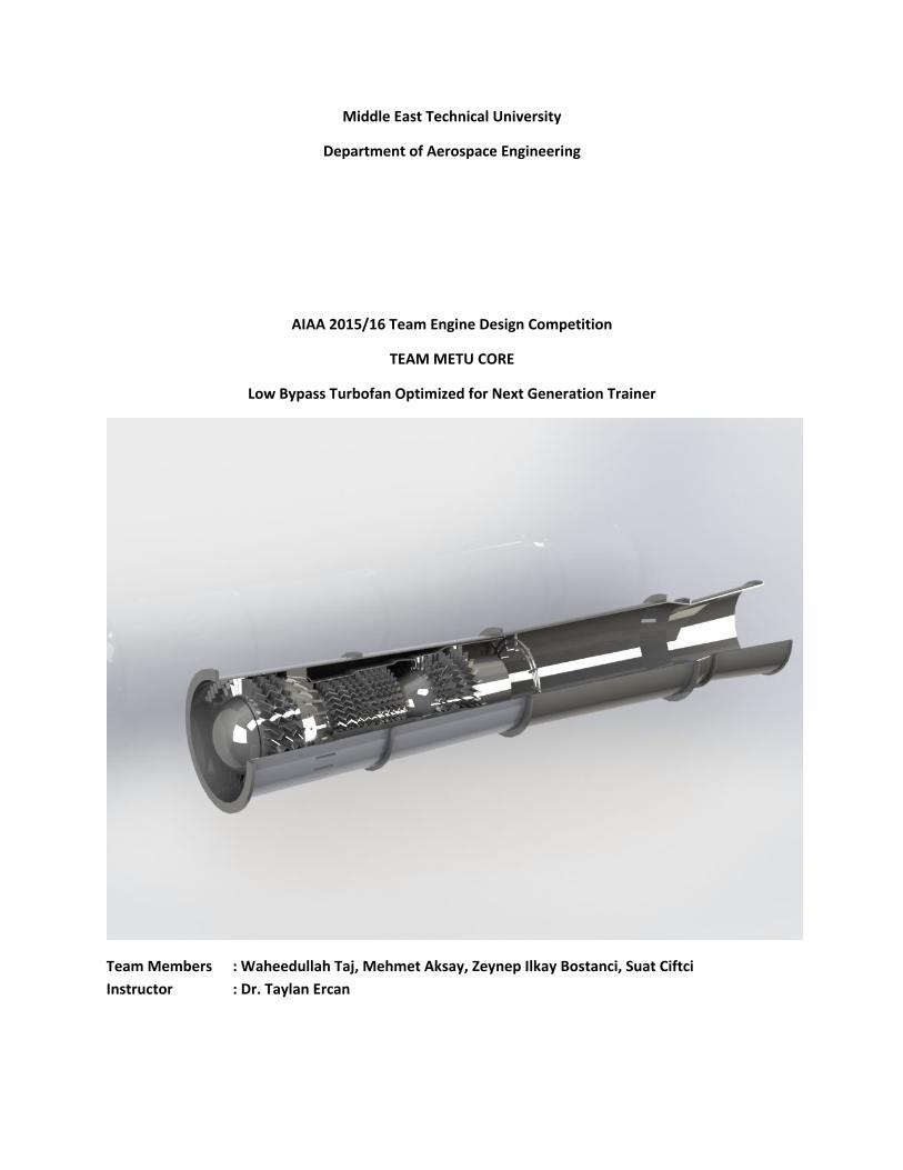
Middle East Technical University
Department of Aerospace Engineering
AIAA 2015/16 Team Engine Design Competition
TEAM METU CORE
Low Bypass Turbofan Optimized for Next Generation Trainer
Team Members : Waheedullah Taj, Mehmet Aksay, Zeynep Ilkay Bostanci, Suat Ciftci
Instructor : Dr. Taylan Ercan
1
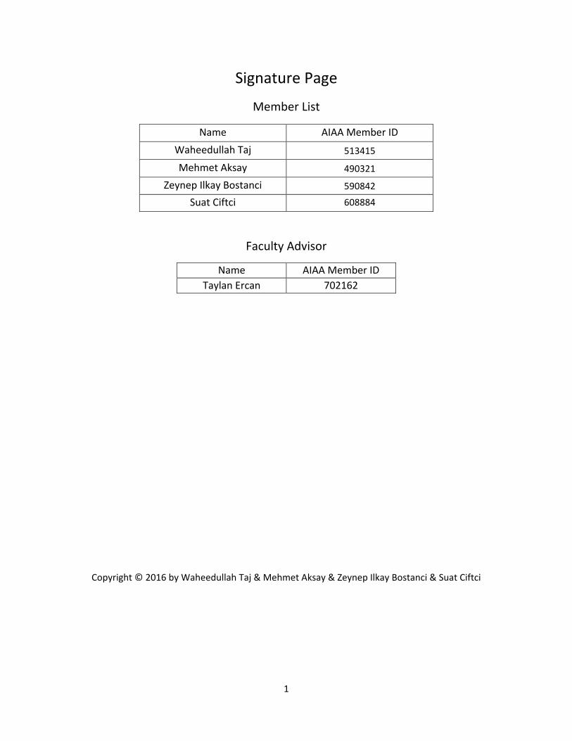
Signature Page
Member List
Name AIAA Member ID
Waheedullah Taj 513415
Mehmet Aksay 490321
Zeynep Ilkay Bostanci 590842
Suat Ciftci 608884
Faculty Advisor
Name AIAA Member ID
Taylan Ercan 702162
Copyright © 2016 by Waheedullah Taj & Mehmet Aksay & Zeynep Ilkay Bostanci & Suat Ciftci
2
Contents
CHAPTER 1 .................................................................................................................................................... 3
CHAPTER 2 .................................................................................................................................................... 4
2.1 Turbofan cycle ............................................................................................................................... 5
2.1.1 OPR vs TET vs Cruise TSFC ..................................................................................................... 6
2.1.2 BPR vs Outer FPR vs Cruise TSFC ........................................................................................... 8
2.1.3 HPC Pressure Ratio vs Outer FPR vs Cruise TSFC .................................................................. 8
2.2 Conclusions ................................................................................................................................... 9
CHAPTER 3 .................................................................................................................................................. 10
3.1 Inlet Design ................................................................................................................................. 10
3.2 Axial Fan Design ............................................................................. Error! Bookmark not defined.
3.2.1 AXIAL COMPRESSOR DESIGN ................................................. Error! Bookmark not defined.
3.3 Combustion chamber desıgn ...................................................................................................... 11
3.4 Turbine Design ............................................................................................................................ 13
3.4.1 HPT Design .......................................................................................................................... 13
3.4.2 LPT Design ........................................................................................................................... 14
3.5 Afterburner Desıgn ..................................................................................................................... 14
CHAPTER 4 Material and Lubrication ..................................................................................................... 15
4.1 LUBRICATION .............................................................................................................................. 15
3
CHAPTER 1
Introduction
This report is the design summary of a low bypass ratio turbofan engine optimized for a next generation
trainer as per requirements of 2015/16 AIAA Foundation Undergraduate Team Engine Design
Competition. The trainer shall be able to simulate advanced 5th generation fighters. It should attain
speeds of Mach 1.3 at 40000 ft. altitude, cruise at Mach 0.85 at 35000 ft. altitude, loiter with Mach 0.5
speeds at 15000 ft. for 30 min. and have a range of 1500 nm and a service ceiling of 51000 ft.
Geometrically the engine must be confined to a length of 51 in. and fan diameter of 20 in. A total of two
engines will be used in the trainer aircraft.
The trainer aircraft under consideration is to replace the T-38 Talon that uses J85-GE-5A. This engine is
used as a baseline and it was completely modelled in Gasturb 12 [1] for future reference and
comparison. Numerous trade studies such as constraint diagram were then prepared to find the best
point for designing the new engine cycle. The new cycle aims to attain the thrust levels at various flight
segments with the lowest mission fuel burn. Since the engine under consideration is a much modern
engine with respect to J85-GE-5A, influence of technological levels on component performance were
analyzed. Similarly a performance margin was allocated for engine component deterioration and
manufacturing imperfections.
Subsequently engine components such as the inlet, fan, compressor, combustion chamber, turbine and
nozzle were designed separately. Various analytical and numerical tools such as Computational Fluid
Dynamics were used during component design. Turbomachines were designed with the help of
AxStream [2] to achieve more realistic and accurate solutions. 3D drawings of the engine components
and the engine as a whole were then drafted in SolidWorks [3].
Special attention was paid to materials selection. Comprehensive literature survey was conducted and
the relative performance and costs of many different materials were compared to come up with the
best materials for use in various engine components.
4
CHAPTER 2
Cycle Design
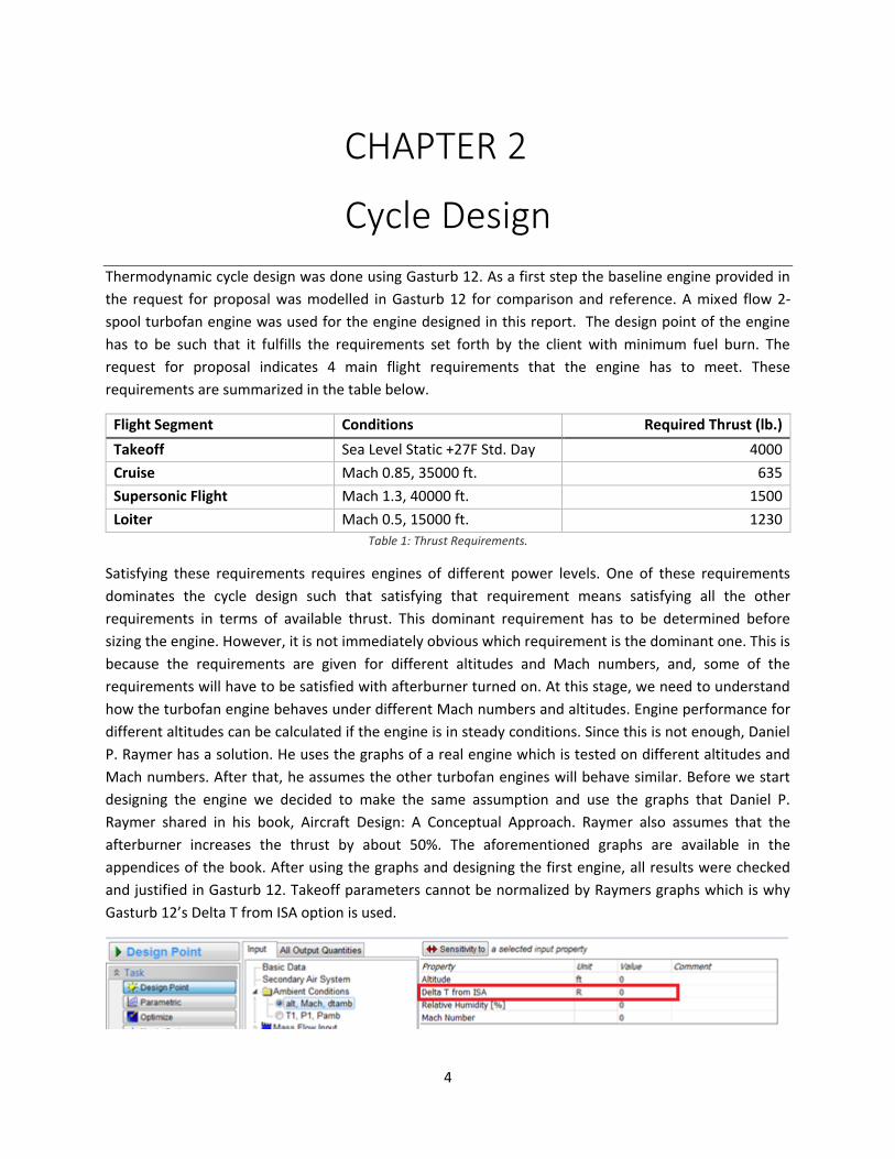
Thermodynamic cycle design was done using Gasturb 12. As a first step the baseline engine provided in
the request for proposal was modelled in Gasturb 12 for comparison and reference. A mixed flow 2-
spool turbofan engine was used for the engine designed in this report. The design point of the engine
has to be such that it fulfills the requirements set forth by the client with minimum fuel burn. The
request for proposal indicates 4 main flight requirements that the engine has to meet. These
requirements are summarized in the table below.
Flight Segment Conditions Required Thrust (lb.)
Takeoff Sea Level Static +27F Std. Day 4000
Cruise Mach 0.85, 35000 ft. 635
Supersonic Flight Mach 1.3, 40000 ft. 1500
Loiter Mach 0.5, 15000 ft. 1230
Table 1: Thrust Requirements.
Satisfying these requirements requires engines of different power levels. One of these requirements
dominates the cycle design such that satisfying that requirement means satisfying all the other
requirements in terms of available thrust. This dominant requirement has to be determined before
sizing the engine. However, it is not immediately obvious which requirement is the dominant one. This is
because the requirements are given for different altitudes and Mach numbers, and, some of the
requirements will have to be satisfied with afterburner turned on. At this stage, we need to understand
how the turbofan engine behaves under different Mach numbers and altitudes. Engine performance for
different altitudes can be calculated if the engine is in steady conditions. Since this is not enough, Daniel
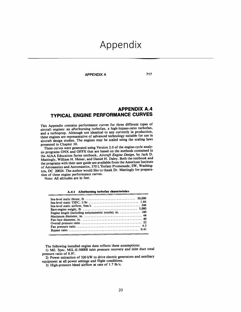
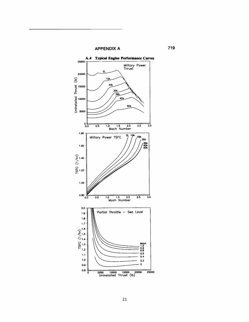
P. Raymer has a solution. He uses the graphs of a real engine which is tested on different altitudes and
Mach numbers. After that, he assumes the other turbofan engines will behave similar. Before we start
designing the engine we decided to make the same assumption and use the graphs that Daniel P.
Raymer shared in his book, Aircraft Design: A Conceptual Approach. Raymer also assumes that the
afterburner increases the thrust by about 50%. The aforementioned graphs are available in the
appendices of the book. After using the graphs and designing the first engine, all results were checked
and justified in Gasturb 12. Takeoff parameters cannot be normalized by Raymers graphs which is why
Gasturb 12’s Delta T from ISA option is used.
5
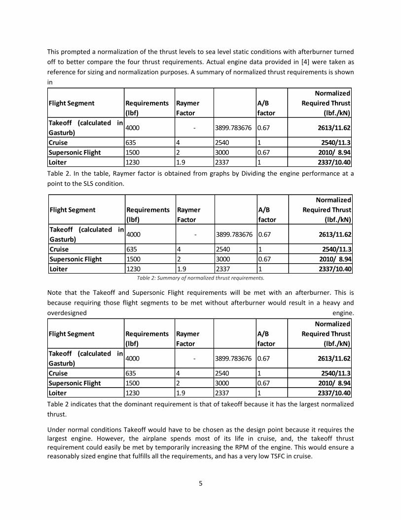
This prompted a normalization of the thrust levels to sea level static conditions with afterburner turned
off to better compare the four thrust requirements. Actual engine data provided in [4] were taken as
reference for sizing and normalization purposes. A summary of normalized thrust requirements is shown
in
Table 2. In the table, Raymer factor is obtained from graphs by Dividing the engine performance at a
point to the SLS condition.
Table 2: Summary of normalized thrust requirements.
Note that the Takeoff and Supersonic Flight requirements will be met with an afterburner. This is
because requiring those flight segments to be met without afterburner would result in a heavy and
overdesigned engine.
Table 2 indicates that the dominant requirement is that of takeoff because it has the largest normalized
thrust.
Under normal conditions Takeoff would have to be chosen as the design point because it requires the largest engine. However, the airplane spends most of its life in cruise, and, the takeoff thrust requirement could easily be met by temporarily increasing the RPM of the engine. This would ensure a reasonably sized engine that fulfills all the requirements, and has a very low TSFC in cruise.
Flight Segment Requirements
(lbf)
Raymer
Factor
A/B
factor
Normalized
Required Thrust
(lbf./kN)
Takeoff (calculated in
Gasturb)4000 - 3899.783676 0.67 2613/11.62
Cruise 635 4 2540 1 2540/11.3
Supersonic Flight 1500 2 3000 0.67 2010/ 8.94
Loiter 1230 1.9 2337 1 2337/10.40
Flight Segment Requirements
(lbf)
Raymer
Factor
A/B
factor
Normalized
Required Thrust
(lbf./kN)
Takeoff (calculated in
Gasturb)4000 - 3899.783676 0.67 2613/11.62
Cruise 635 4 2540 1 2540/11.3
Supersonic Flight 1500 2 3000 0.67 2010/ 8.94
Loiter 1230 1.9 2337 1 2337/10.40
Flight Segment Requirements
(lbf)
Raymer
Factor
A/B
factor
Normalized
Required Thrust
(lbf./kN)
Takeoff (calculated in
Gasturb)4000 - 3899.783676 0.67 2613/11.62
Cruise 635 4 2540 1 2540/11.3
Supersonic Flight 1500 2 3000 0.67 2010/ 8.94
Loiter 1230 1.9 2337 1 2337/10.40
6
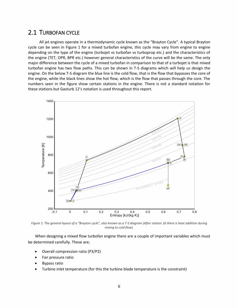
2.1 TURBOFAN CYCLE All jet engines operate in a thermodynamic cycle known as the “Brayton Cycle”. A typical Brayton
cycle can be seen in Figure 1 for a mixed turbofan engine, this cycle may vary from engine to engine depending on the type of the engine (turbojet vs turbofan vs turboprop etc.) and the characteristics of the engine (TET, OPR, BPR etc.) however general characteristics of the curve will be the same. The only major difference between the cycle of a mixed turbofan in comparison to that of a turbojet is that mixed turbofan engine has two flow paths. This can be shown in T-S diagrams which will help us design the engine. On the below T-S diagram the blue line is the cold flow, that is the flow that bypasses the core of the engine, while the black lines show the hot flow, which is the flow that passes through the core. The numbers seen in the figure show certain stations in the engine. There is not a standard notation for these stations but Gasturb 12’s notation is used throughout this report.
Figure 1: The general layout of a “Brayton cycle”, also known as a T-S diagram (After station 16 there is heat addition during
mixing to cold flow).
When designing a mixed flow turbofan engine there are a couple of important variables which must
be determined carefully. These are;
Overall compression ratio (P3/P2)
Fan pressure ratio
Bypass ratio
Turbine inlet temperature (for this the turbine blade temperature is the constraint)
7
The process of designing an engine is actually a tradeoff of these parameters. All of these
parameters are linked to each other in a sophisticated way and changing one would automatically imply
a change in some others. To understand how these variables affect the engine performance we need to
plot many of these parameters on the same graph and find the points that suits our interests the most.
To avoid an overly complicated graph we opted to plot and compare only 2 variables against TSFC and
thrust. When such plots are obtained and an optimum point is chosen, other variables and plots also
have to be observed and checked if they are within reasonable limits. If not the selection of the design
point has to be iterated.
2.1.1 OPR vs TET vs Cruise TSFC The first graph that should be analyzed is HPC Pressure ratio vs TET vs TSFC. For every bypass ratio,
we design a whole different engine and for every and each one of them the OPR must be optimized.
OPR is defined as the multiplication of inner fan pressure ratio and HPC pressure ratio. However, in
order to simulate a change in OPR it is sufficient to change one of these only. Thus only HPC pressure
ratio is varied to change OPR while performing the aforementioned optimizations.
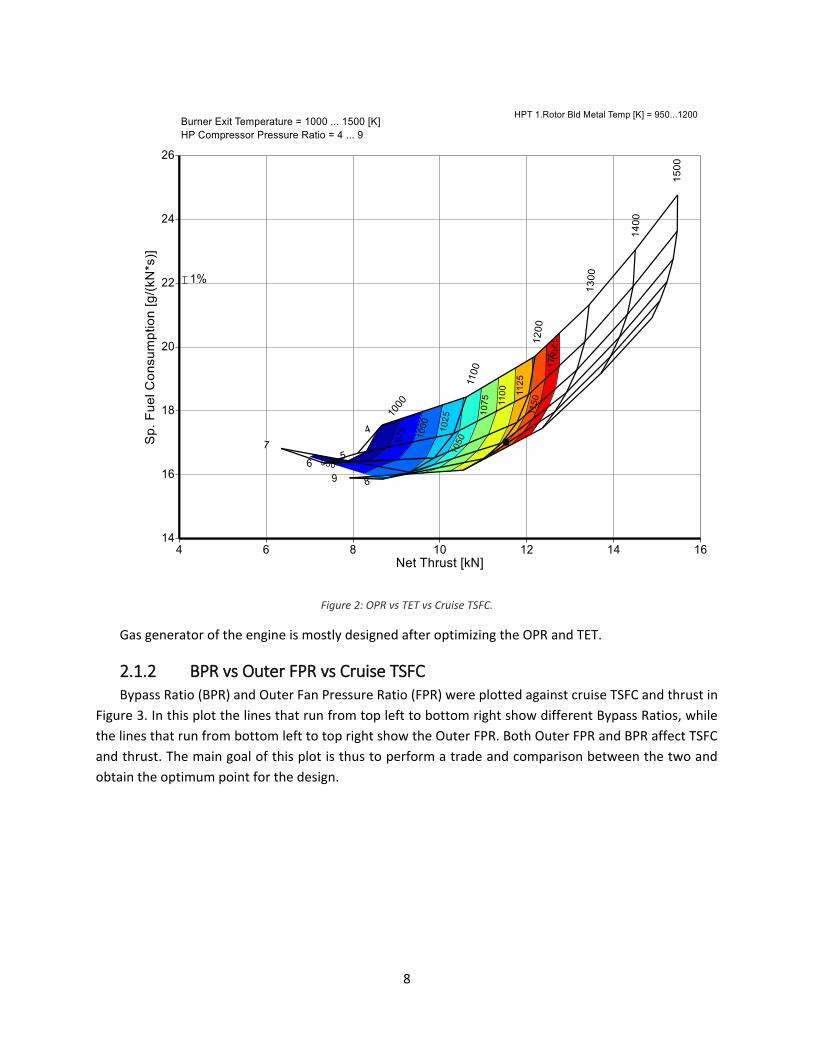
Overall Pressure Ratio (OPR) and Turbine Entry Temperature (TET) were plotted against Cruise TSFC
and thrust in Figure 2. In this figure, blade temperature is shown with contours while TET is visualized
with near vertical solid lines and HPC Pressure Ratio lines are the solid lines with values between 4 and 9.
In this graph the black dot is the final engine design point. There are 2 limitations in this graph. Firstly,
the Turbine blade temperature should not be higher than 1150K since the Inconel 718 material is not
durable at higher temperatures. Above the 1200 K blade temperature was not included in the contours.
Our main limitation is the blade temperature and it can be seen that minimum TSFC for the given thrust
of 11.3 kN, is obtained at the design point shown.
8
Figure 2: OPR vs TET vs Cruise TSFC.
Gas generator of the engine is mostly designed after optimizing the OPR and TET.
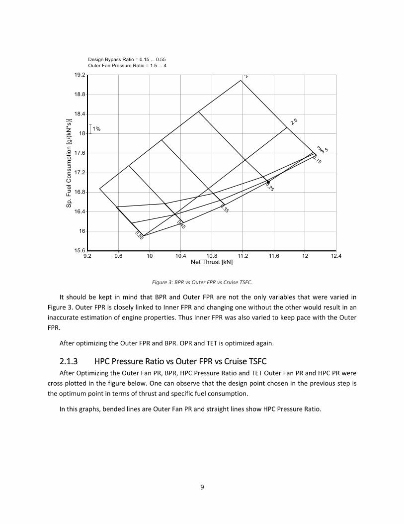
2.1.2 BPR vs Outer FPR vs Cruise TSFC Bypass Ratio (BPR) and Outer Fan Pressure Ratio (FPR) were plotted against cruise TSFC and thrust in
Figure 3. In this plot the lines that run from top left to bottom right show different Bypass Ratios, while
the lines that run from bottom left to top right show the Outer FPR. Both Outer FPR and BPR affect TSFC
and thrust. The main goal of this plot is thus to perform a trade and comparison between the two and
obtain the optimum point for the design.
9
Figure 3: BPR vs Outer FPR vs Cruise TSFC.
It should be kept in mind that BPR and Outer FPR are not the only variables that were varied in
Figure 3. Outer FPR is closely linked to Inner FPR and changing one without the other would result in an
inaccurate estimation of engine properties. Thus Inner FPR was also varied to keep pace with the Outer
FPR.
After optimizing the Outer FPR and BPR. OPR and TET is optimized again.
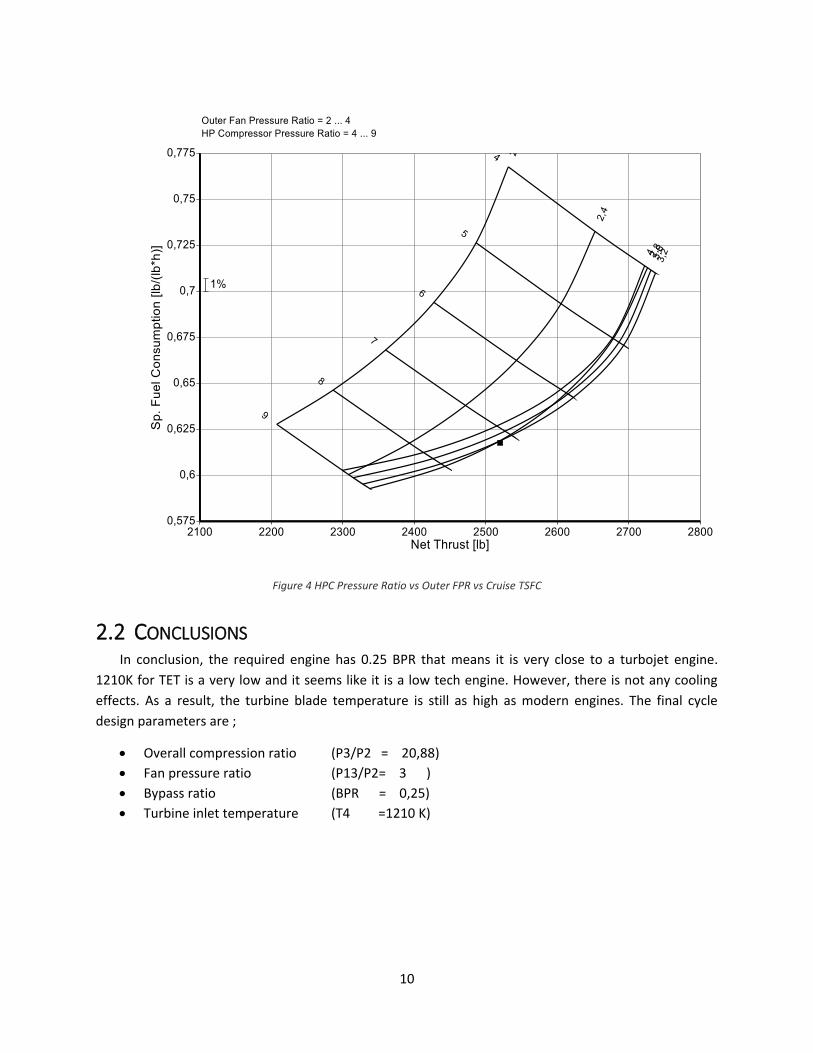
2.1.3 HPC Pressure Ratio vs Outer FPR vs Cruise TSFC After Optimizing the Outer Fan PR, BPR, HPC Pressure Ratio and TET Outer Fan PR and HPC PR were
cross plotted in the figure below. One can observe that the design point chosen in the previous step is
the optimum point in terms of thrust and specific fuel consumption.
In this graphs, bended lines are Outer Fan PR and straight lines show HPC Pressure Ratio.
10
Figure 4 HPC Pressure Ratio vs Outer FPR vs Cruise TSFC
2.2 CONCLUSIONS In conclusion, the required engine has 0.25 BPR that means it is very close to a turbojet engine.
1210K for TET is a very low and it seems like it is a low tech engine. However, there is not any cooling
effects. As a result, the turbine blade temperature is still as high as modern engines. The final cycle
design parameters are ;
Overall compression ratio (P3/P2 = 20,88)
Fan pressure ratio (P13/P2= 3 )
Bypass ratio (BPR = 0,25)
Turbine inlet temperature (T4 =1210 K)
11
CHAPTER 3
Component Design
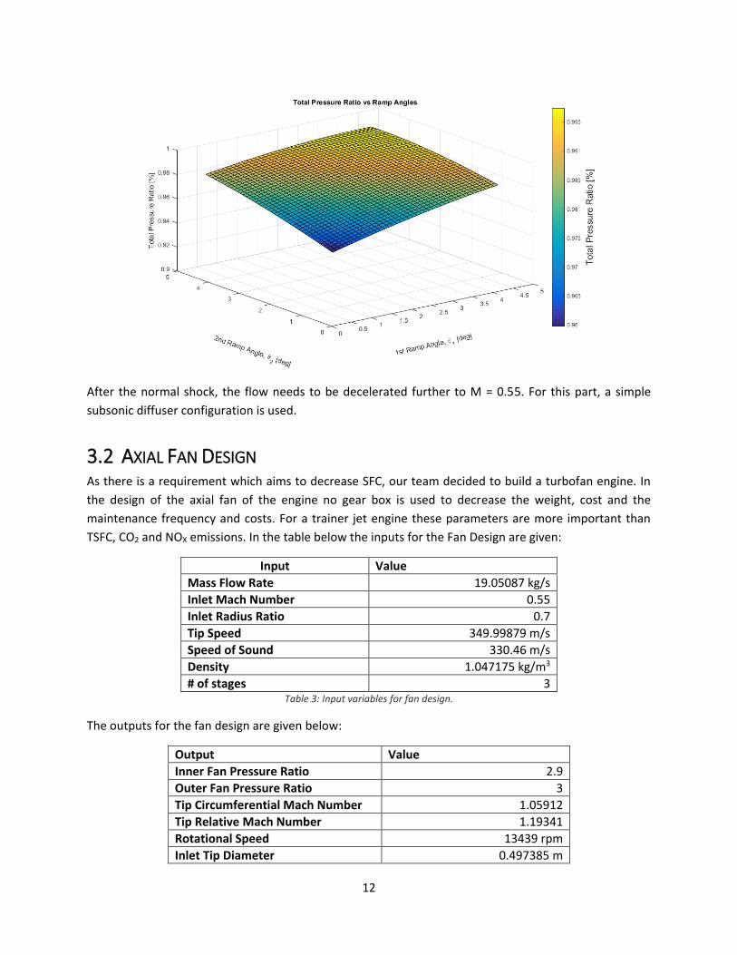
3.1 INLET DESIGN Inlet design has always been one of the important parts of the engine design process since inlet has the
main purpose of decelerating the flow while maintaining maximum total pressure. It is even more
important in supersonic flight conditions because of the shockwave occurance. A carefully designed
inlet will allow the flow to decelerate to operating conditions of the compressor with maximum
efficiency. In this project, the dependency of total pressure ratio with respect to ramp numbers and
ramp angles were investigated for an external compression inlet. A MATLAB code is written to obtain
the optimum number of ramps and ramp angles for an aircraft cruising at M = 1.2, 1.3 and 1.4 for
minimizing the pressure loss associated with the shocks.
In an external compression type, the flow goes through one or more oblique shocks using the ramps
outside the inlet - and one final normal shock at the lip. By this setup the normal shock strength is
reduced, resulting in less pressure loss. Inside of the inlet works as a subsonic diffuser, decelerating the
flow further into the compressor's required inlet Mach number.
Theoretically, having the maximum pressure recovery requires infinitely many weak oblique shocks. But
in reality, this configuration would have some drawbacks such as spoiling the flow field, being harder to
manufacture, need for lengthy ramps (resulting in extra weight) etc.
The best ramp angle combinations for 2-ramp case is as follows:
Mach Number 1st Ramp Angle [deg] 2nd Ramp Angle [deg]
1.2 1.6 1.9
1.3 2.7 3.1
1.4 4.0 4.3
As can be seen from the table, a variable 2-ramp inlet configuration would be the best.
For M = 1.4
12
After the normal shock, the flow needs to be decelerated further to M = 0.55. For this part, a simple
subsonic diffuser configuration is used.
3.2 AXIAL FAN DESIGN As there is a requirement which aims to decrease SFC, our team decided to build a turbofan engine. In
the design of the axial fan of the engine no gear box is used to decrease the weight, cost and the
maintenance frequency and costs. For a trainer jet engine these parameters are more important than
TSFC, CO2 and NOX emissions. In the table below the inputs for the Fan Design are given:
Input Value
Mass Flow Rate 19.05087 kg/s
Inlet Mach Number 0.55
Inlet Radius Ratio 0.7
Tip Speed 349.99879 m/s
Speed of Sound 330.46 m/s
Density 1.047175 kg/m3
# of stages 3 Table 3: Input variables for fan design.
The outputs for the fan design are given below:
Output Value
Inner Fan Pressure Ratio 2.9
Outer Fan Pressure Ratio 3
Tip Circumferential Mach Number 1.05912
Tip Relative Mach Number 1.19341
Rotational Speed 13439 rpm
Inlet Tip Diameter 0.497385 m
13
Inlet Hub Diameter 0.348169 m
Aerodynamic Interface Plane 0.1942817 m2 Table 4: Properties of the designed fan.
As seen from the table above the inlet diameter is smaller than the diameter requested by RFP which is
0.508 m. The diameter of the fan is near the limits due to our interest in increasing bypass ratio to
decrease SFC as much as we can. The fan has a 3 stage structure, because the fan was giving best
pressure ratio for minimum SFC in that case.
3.2.1 AXIAL COMPRESSOR DESIGN Our design has two shaft architecture to decrease the complexity and weight of the engine, decrease
the cost and maintenance frequency. Through our analysis, we have seen that our OPR needs to be
22.88 and HPC pressure ratio is 7.2. To do that with the most efficient number of blades we have
decided that the axial compressor will be consists of 9 stages, this is because of the fact that loading of
the stages increases and the efficiency of the stages increases as the number of stages increases. In
addition to these our team has decided to use variable IGV to be able to get the least losses due to
velocity. To satisfy the total length requirement given in the RFP (which is 2.7432 meters) the best
solution was these. The mass flow rate, inlet total pressure, inlet total temperature, outlet total
pressure and shaft rotational speed are obtained from the GasTurb and put into AxStream to design the
HPC.
Property Pressure Ratio Internal Total to Total
Efficiency
Polytropic Efficiency
Value 0.9283 0.9021 21424
Table 5: Summary of high pressure compressor properties.
3.3 COMBUSTION CHAMBER DESIGN Combustor of this engine is optimized to have high-combustion efficiency, reliable and smooth ignition
(both on the ground and in case of flameout in high altitudes), wide stability limits, low pressure loss,
good outlet temperature distribution for turbine blades, low emission, low cost, low weight, durability
and maintainability. An annular type combustor is designed since it has lower pressure loss than other
combustor types.
Wall cooling is an important aspect of combustor design. This engine includes angled effusion cooling
(AEC) whereby multiple patterns of small holes are drilled through the liner wall at a shallow angle to its
surface. With this scheme, the cooling air flows through the liner wall, first removing heat from the wall
itself, and then providing a thermal barrier between the wall and the hot combustion gases.
Required diffuser area ratio is calculated as 3.76, which results in a pressure loss of … and efficiency of ….
The 95% of the total air coming is used for burning and the remaining 5% is used for cooling.
Equivalence ratio of the engine is selected as 1.7 for primary zone and 0.7 for secondary zone. Reference
velocity is taken as 18 m/s. Based on these assumptions, residence time, loading factor and combustor
intensity is calculated as:
14
Property Residence
Time
Combustion
Intensity
Combustor Intensity Combustion
Efficiency
Fuel-to-air
Ratio
Value 5 ms 40 MW/𝑚3bar 0.2 kg/(𝑏𝑎𝑟1.8𝑚3𝑠) 99.95% 0.012997
Figure 5: Summary of combustion chamber properties.
Then, using correlations given in Lefebvre, combustor loading parameter is calculated and it
corresponds to a 99.95% efficiency in combustion chamber. That result matches with the GasTurb
output.
3.4 TURBINE DESIGN Turbines are another group of turbomachinery that extract some energy from the flow to drive the
compressors. Turbine technology is especially important because turbine blades are exposed to a
combination of high thermal and mechanical loads. Just like compressors, there are two types of
turbines; centrifugal and axial. However centrifugal turbines are not as efficient in large engines as axial
turbines and hence the latter was used in this engine. Two different turbines were used; High Pressure
Turbine (HPT) and Low Pressure Turbine (LPT). These are connected to the compressor and the fan, via
different shafts, respectively. Similar to the compressor, Axstream was used to design turbine blades
and stages.
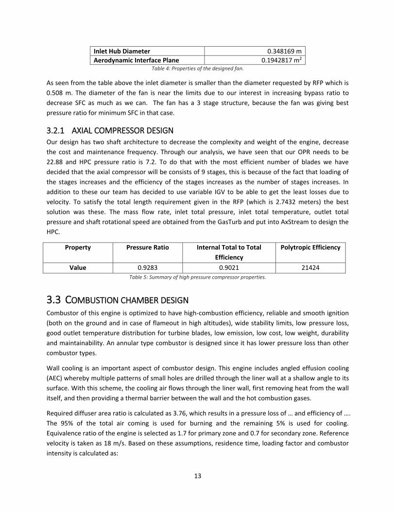
3.4.1 HPT Design High Pressure Turbine immediately follows the combustion chamber and it extracts power from the flow
to drive the compressor. To design the HPT in Axstream a number of predefined parameters need to be
specified. These include total and static pressures and temperatures before and after the turbine, inlet
flow angle, and constraints on hub and tip radii. These were obtained from Gasturb calculations. Stage
loading coefficient was used as the main constraint in determining the number of stages. Thus two
stages were used in the HPT after a careful consideration of all the parameters involved, such as weight,
mechanical complexity, efficiency and cost. The shape of the stage is shown below.
Figure 6: Schematic view of the HPT rotor and stator.
Some properties of the HPT obtained from both Axstream and Gasturb are shown below.
Property Isentropic Efficiency
(Gasturb)
Isentropic Efficiency
(Axstream)
Shaft RPM Number of Stages
Value 0.9283 0.9021 21424 2
Figure 7: Summary of high pressure turbine properties.
15
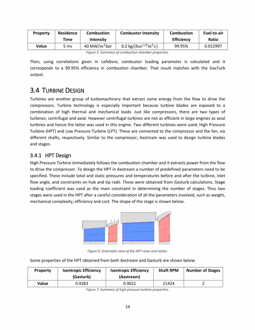
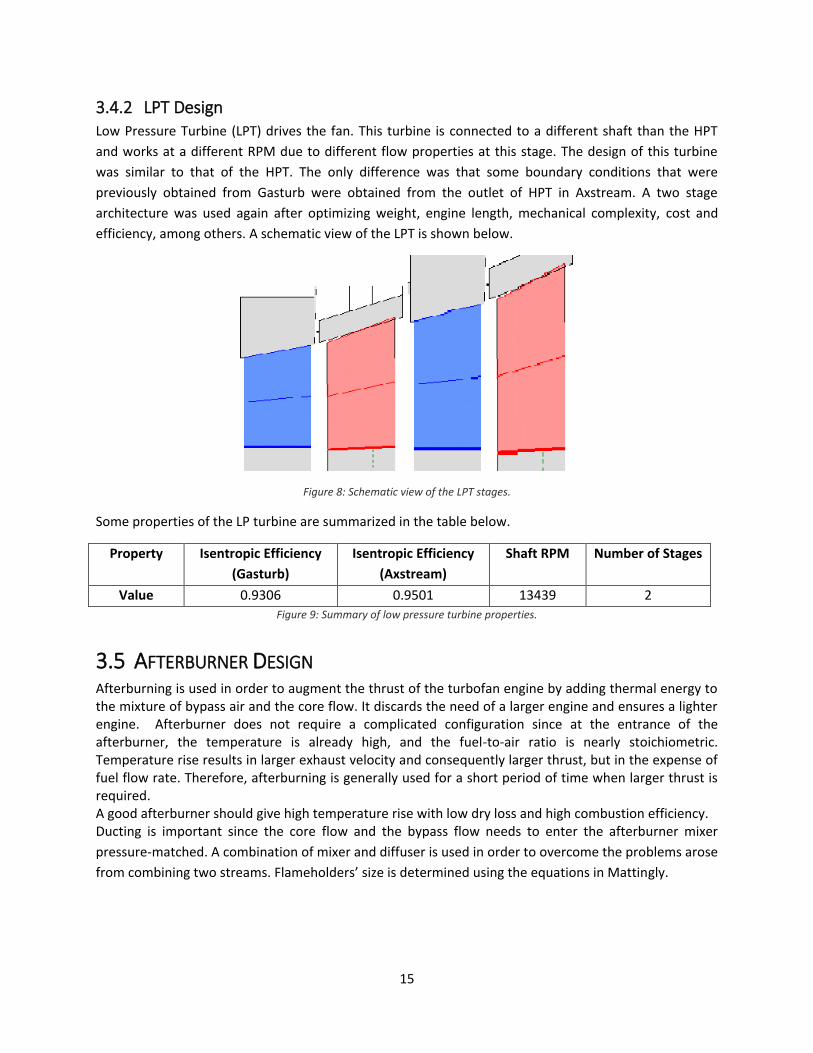
3.4.2 LPT Design Low Pressure Turbine (LPT) drives the fan. This turbine is connected to a different shaft than the HPT
and works at a different RPM due to different flow properties at this stage. The design of this turbine
was similar to that of the HPT. The only difference was that some boundary conditions that were
previously obtained from Gasturb were obtained from the outlet of HPT in Axstream. A two stage
architecture was used again after optimizing weight, engine length, mechanical complexity, cost and
efficiency, among others. A schematic view of the LPT is shown below.
Figure 8: Schematic view of the LPT stages.
Some properties of the LP turbine are summarized in the table below.
Property Isentropic Efficiency
(Gasturb)
Isentropic Efficiency
(Axstream)
Shaft RPM Number of Stages
Value 0.9306 0.9501 13439 2
Figure 9: Summary of low pressure turbine properties.
3.5 AFTERBURNER DESIGN Afterburning is used in order to augment the thrust of the turbofan engine by adding thermal energy to the mixture of bypass air and the core flow. It discards the need of a larger engine and ensures a lighter engine. Afterburner does not require a complicated configuration since at the entrance of the afterburner, the temperature is already high, and the fuel-to-air ratio is nearly stoichiometric. Temperature rise results in larger exhaust velocity and consequently larger thrust, but in the expense of fuel flow rate. Therefore, afterburning is generally used for a short period of time when larger thrust is required. A good afterburner should give high temperature rise with low dry loss and high combustion efficiency. Ducting is important since the core flow and the bypass flow needs to enter the afterburner mixer
pressure-matched. A combination of mixer and diffuser is used in order to overcome the problems arose
from combining two streams. Flameholders’ size is determined using the equations in Mattingly.
16
CHAPTER 4
MATERIAL AND LUBRICATION
4.1 LUBRICATION An aircraft engine has a lot of mechanical parts which are exposed to friction and high temperatures
through their life. As the power of the engine increases, the lubrication technology becomes more
important. Some roles of lubrication which are taken from Linke-Diesinger[5] given below:
Lubrication of the rotor bearings
Lubrication of the gears and bearings of the gearboxes
Cooling of the bearings especially in the turbine area
Removal of the contaminants from the lubricant
Support of the sealing of the carbon bearing seals
Supplying of a squeeze film between the bearing outer races and their housings for oil
dampened bearings. Oil damping dampens the transmission of dynamic loads of the rotors to
the casings. This feature reduces the vibration levels and the fatigue loads for the casings.
Lubricant can be used for both for decreasing the friction between the metal parts and decreasing
temperature of the hot parts. Friction is divided into 3 as stated by Linke-Diesinger[5] according to the
movement type. These are; wiping, sliding and rolling type of frictions. In bearings, as their names
suggest mostly sliding and rolling type frictions are seen while gear teeth are usually subjected to wiping
type friction. Today mostly used engine oils are the oils which can be operated for a wide range of
temperatures and synthetic[5].
The main characteristics of engine oils are viscosity, pour point, flash point, pressure resistance,
oxidation resistance and thermal stability[5].
Viscosity: Viscosity is a fluid’s internal resistance to deformation. Viscosity of an oil depends on the
temperature. As temperature increases viscosity decreases such that a low viscosity fluid at a high
temperature will be less useful as a lubricant. The viscosity unit is usually referred as centistokes(Cs)[5].
Pour point: The pour point is the temperature at which the viscosity becomes very large that oil stops
flowing[5].
Flash point: The lowest temperature at which the fluid is able to form a mixture with air that is
ignitable[5].
Pressure resistance: The max pressure at which the lubricant loses its ability to prevent the contact of
the moving surfaces[5].
17
Oxidation resistance: Oxidation is the process of reacting with oxygen. When lubricant oxidizes its
viscosity increases. The oxidation usually becomes important after a certain temperature[5].
Thermal stability: Thermal stability is the resistance of the oil to decomposition of the oil compounds at
high temperatures. After a certain temperature the lubricant is gets divided into its compounds by a
chemical decomposition[5].
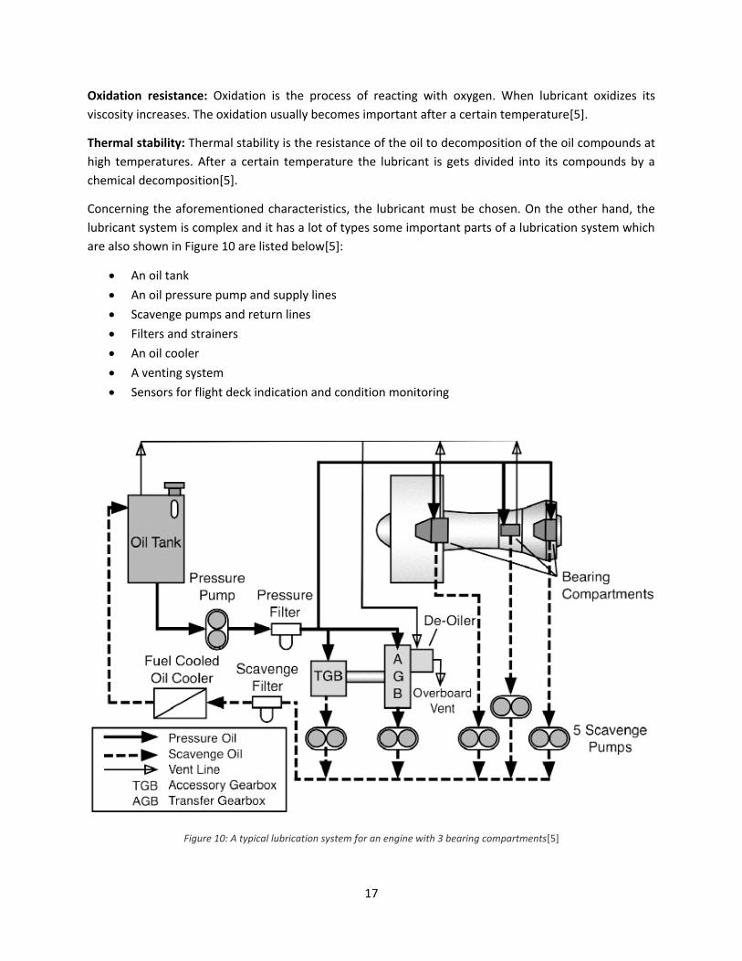
Concerning the aforementioned characteristics, the lubricant must be chosen. On the other hand, the
lubricant system is complex and it has a lot of types some important parts of a lubrication system which
are also shown in Figure 10 are listed below[5]:
An oil tank
An oil pressure pump and supply lines
Scavenge pumps and return lines
Filters and strainers
An oil cooler
A venting system
Sensors for flight deck indication and condition monitoring
Figure 10: A typical lubrication system for an engine with 3 bearing compartments[5]
18
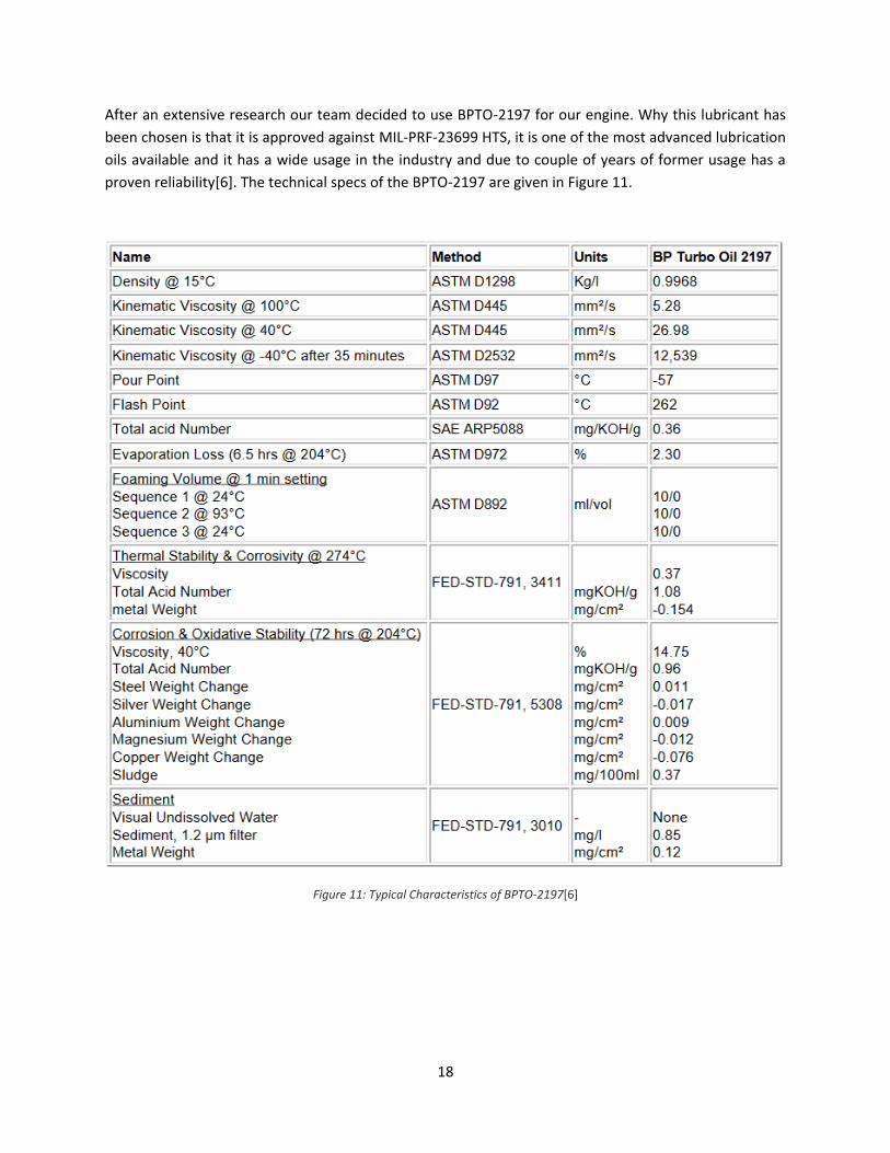
After an extensive research our team decided to use BPTO-2197 for our engine. Why this lubricant has
been chosen is that it is approved against MIL-PRF-23699 HTS, it is one of the most advanced lubrication
oils available and it has a wide usage in the industry and due to couple of years of former usage has a
proven reliability[6]. The technical specs of the BPTO-2197 are given in Figure 11.
Figure 11: Typical Characteristics of BPTO-2197[6]
19
References
[1] “Gasturb 12.” Gasturb GmbH, Aachen Germany, 2016.
[2] “AxStream.” SoftInWay Inc., Burlington, MA, 2016.
[3] “SOLIDWORKS.” Dassault Systemes, 2016.
[4] D. P. Raymer, Aircraft Design: A Conceptual Approach, 2nd ed. Washington, DC: American Institute of Aeronautics and Astronautics, Inc., 1992.
[5] A. Linke-Diesinger, Systems of Commercial Turbofan Engines - An Introduction to Systems Functions. Springer-Verlag Berlin Heidelberg, 2008.
[6] BP, “BP Turbo Oil 2197 Product Data,” 2012. [Online]. Available: https://www.fmv.se/FTP/Drivmedel 2016/datablad/M0741-8590XX_BPTO2197.pdf.
[7] Mattingly, J. D., Heiser, W. H., & Daley, D. H. (1987). Aircraft engine design. Washington, D.C.: American Institute of Aeronautics and Astronautics.
[8] Lefebvre, A. H. (1983). Gas turbine combustion. Washington: Hemisphere Pub.
[9] Cohen, H., Rogers, G. F., & Saravanamuttoo, H. I. (1987). Gas turbine theory. Burnt Mill, Harlow, Essex, England: Longman Scientific & Technical.
20
Appendix
21

22