mifare classic operations with trf79xxa nfc/rfid transceivers
TRANSCRIPT

Mifare Classic Operations with TRF79xxA NFC/RFID Transceivers
S2 Microcontroller DivisionNFC/RFID Applications Team03/2014
1

Agenda• Mifare Classic Operations Overview & Standards based timings• Technical Information about using the TRF79xxA devices with the
Mifare Classic transponders– Activation & Selection– Authentication– Read Blocks & Sectors– Writing Blocks & Sectors
• Handling 7 byte UID Mifare Classic Tags• Timing Observations
– Activation and Selection– Authenticaiton– Read Block– Read Sector– Conclusion
• Backup Slides 2

Mifare Classic Operations Overview• Mifare Classic uses ISO14443A air interface protocol, so TRF79xxA is
setup for ISO14443A, and Mifare Classic card UID is read and then selected.
• After this point, a three round authentication must take place. This is where Mifare deviates from the ISO standard so the TRF79xxA must be placed in Direct Mode 0 (Analog Front End Mode).
• For TX, this is the relationship of MOD pin to carrier, as the MCU must modulate the RF according to the ISO14443A air interface and do so in accordance with Mifare Classic protocol.
• For RX, this is the digitized data bit stream from I/O_6, which the MCU must decode, according to the ISO14443A air interface standard.
3

Mifare Classic Activation Sequence
• The bit 6 in the SAK indicates, whether the PICC is compliant to the ISO/IEC14443-4 or not. However, it does not necessarily indicate, whether the PICC supports the MIFARE Protocol or not.
4

Mifare Classic Anti-collision Loop
5
• Mifare tags recently started being released with double sized (7 byte) UID’s. Mifare 4 byte UID’s are now labeled “non-unique”. Currently there are no triple sized UID Mifare tags.

ISO14443A Anti-collision Loop
6

ISO14443A Selection Process
7

NXP’s Mifare Tag Types• You can see in the table below the different functionality available in
NXP’s MIFARE tags.
• These tags are quite common in the field.
8

ISO14443A Standard Important Timings
9
• 128/fc = 9.435uSec = tb (106kbps data rate)• 64/fc = 4.719uSec = tx time • 32/fc = 2.359uSec = t1 time

Technical Information• The following several slides go into the details of using the TRF79xx
devices first in Direct Mode 2 to activate the card and select it, then in Direct Mode 0 during Mifare Card specific operations.– Note: subsequent slides do not show all register configurations, but this has
been done beforehand, per the TRF79xxA datasheets.
10
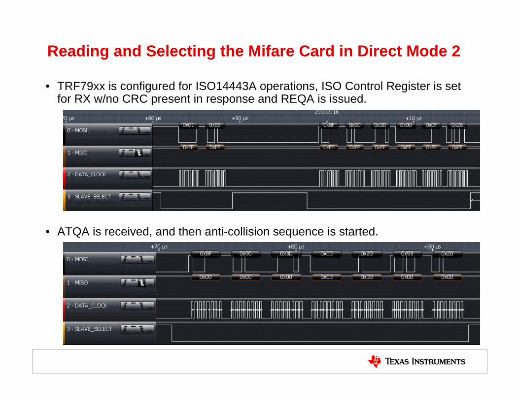
Reading and Selecting the Mifare Card in Direct Mode 2
• TRF79xx is configured for ISO14443A operations, ISO Control Register is set for RX w/no CRC present in response and REQA is issued.
• ATQA is received, and then anti-collision sequence is started.
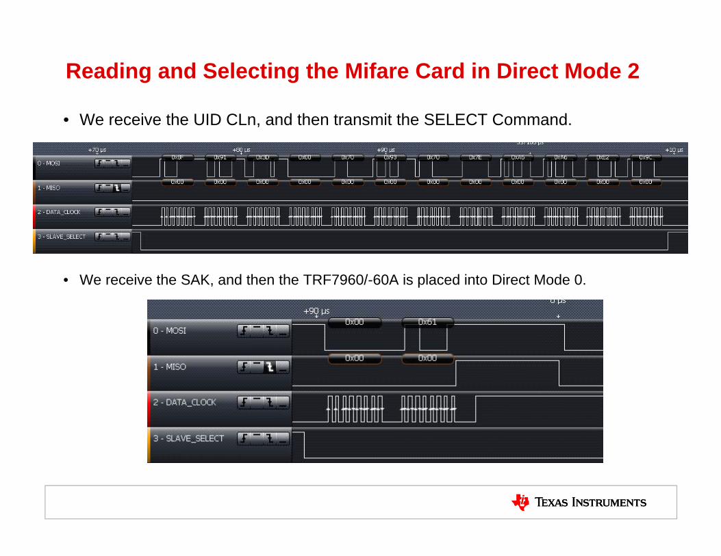
Reading and Selecting the Mifare Card in Direct Mode 2
• We receive the UID CLn, and then transmit the SELECT Command.
• We receive the SAK, and then the TRF7960/-60A is placed into Direct Mode 0.

Reading and Selecting the Mifare Card in Direct Mode 2(cont., TRF7970A DM0 specific)
• We receive the UID CLn, and then transmit the SELECT Command.
• We receive the SAK, and then the TRF7970A is placed into Direct Mode 0. NOTE : see extra 8 clocks after sending 0x61 to Chip Status Control Register (Direct Mode 0) setting
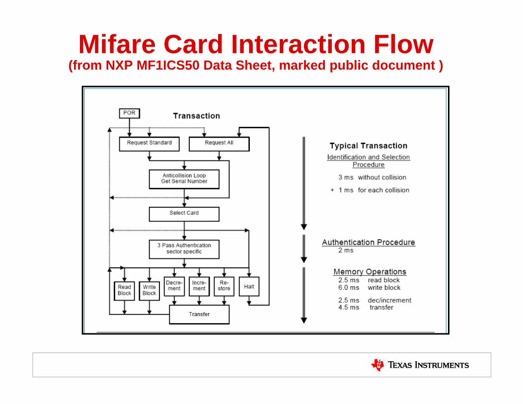
Mifare Card Interaction Flow (from NXP MF1ICS50 Data Sheet, marked public document )

Three pass authentication sequence
1. The reader specifies the sector to be accessed and chooses key A or B.2. The card reads the secret key and the access conditions from the sector
trailer. Then the card sends a random number as the challenge to the reader (pass one).
3. The reader calculates the response using the secret key and additional input. The response, together with a random challenge from the reader, is then transmitted to the card (pass two).
4. The card verifies the response of the reader by comparing it with its own challenge and then it calculates the response to the challenge and transmits it (pass three).
5. The reader verifies the response of the card by comparing it to its own challenge.
NOTE: After transmission of the first random challenge the communication between card and reader is encrypted.

Three pass authentication sequence (cont.)
• The AUTH protocol does:– Reader sends 32 bit random number (+ error correction)– Card responds with 32 bit key stream XOR a derivative of the reader
random number XOR its own random number– Reader responds with 32 bit key stream XOR the card random number
• NOTE: None of this information can really be checked for plausibility without the secret keys, as it's either random or encrypted (or both mixed). This is why you will see later in the slides that 38 bits are sent out instead of the 80 bits that one might expect from reading publicly available NXP documents.

Using the TRF79xx in Direct Mode 0 for Authentication
• At this point, the MOD pin is being driven by the MCU, which in turn is driving the TRF79xx transmitter, in accordance with the ISO14443A air interface specifications. For example, below is a logic analyzer capture showing the TRF79xx being put into Direct Mode 0, and also shown below is exact same thing, but on oscilloscope, so that the RF output can be correlated to how MOD pin is being driven. (next slide shows full size of the RF screen shot)

ISO14443A SOF (in Direct Mode 0)• Per the ISO14443A Standard, this is sequence Z, which is used for the PCD to
PICC Start of Communication (SOF)

Using the TRF79xx in Direct Mode 0 for Authentication
• Here is another example, captured with TRF7970A this time, showing SOF after going into DM0.
– Note extra clock cycle after register 0x00 is written with 0x61.
• Cursors are on MOD (ignore MISO line here) starting with the ISO14443A SOF (Sequence Z) - as when MOD is high, TX is off
• This is followed by bit stream starting with: XXXXYXYX…(11110101)…0xF5…and goes on.
X X X X Y X XY
1 1 1 1 0 1 10
F 5
X Y X
etc…
Z
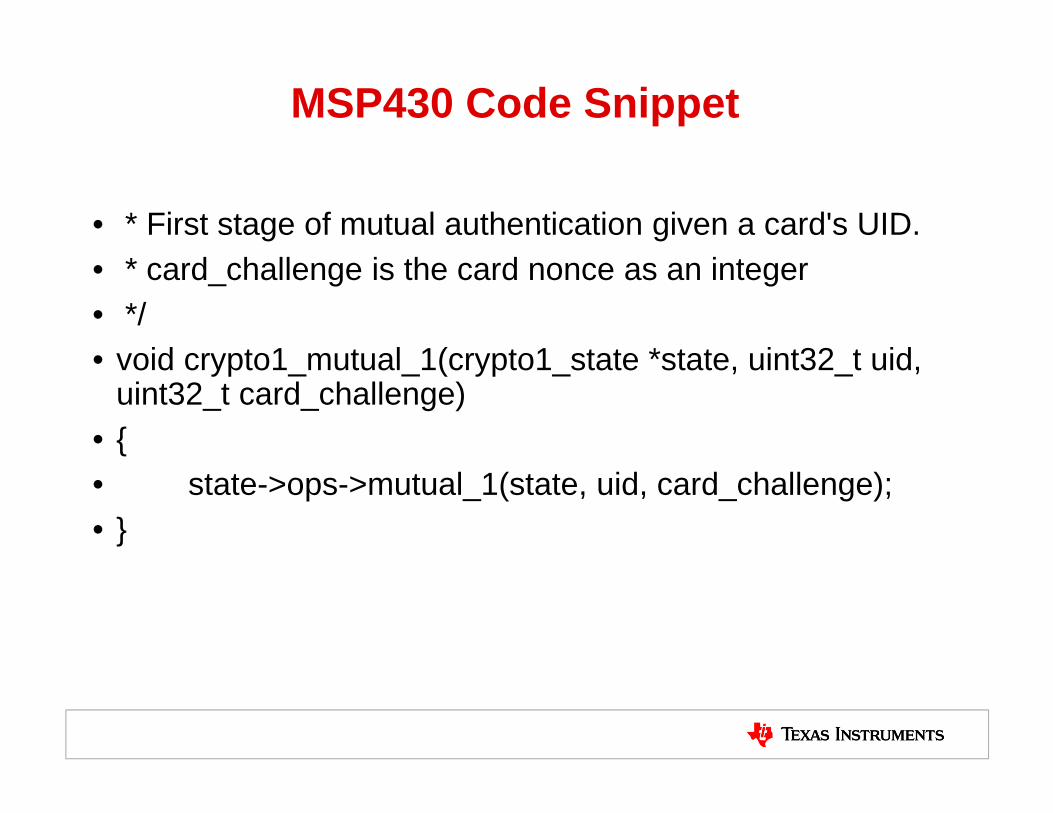
MSP430 Code Snippet
• * First stage of mutual authentication given a card's UID.• * card_challenge is the card nonce as an integer• */• void crypto1_mutual_1(crypto1_state *state, uint32_t uid,
uint32_t card_challenge)• {• state->ops->mutual_1(state, uid, card_challenge);• }

First TRF79xx TX Sequence Out in DM0 for Mifare Authentication
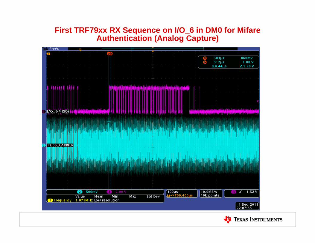
First TRF79xx RX Sequence on I/O_6 in DM0 for MifareAuthentication (Analog Capture)

First TRF79xx RX Sequence on I/O_6 in DM0 for Mifare Authentication (cont., digital capture of previous slide)
• PICC is communicating back @ 106kbps (fc/128), so:– The following sequences are defined:
• Sequence D: the carrier shall be modulated with the subcarrier for the first half (50 %) of the bit duration,
• Sequence E: the carrier shall be modulated with the subcarrier for the second half (50 %) of the bit duration,
• Sequence F: the carrier is not modulated with the subcarrier for one bit duration.
– Bit coding shall be Manchester with the following definitions:• logic "1": Sequence D• logic "0": Sequence E• Start of Communication: Sequence D• End of Communication: Sequence F• No Information: No Subcarrier.
• T1:T2 cursors are ISO14443A PICC to PCD SOF (Sequence D)

First TRF79xx RX Sequence on I/O_6 in DM0 for Mifare Authentication (cont., digital capture of previous slide)
• Data is encrypted:

Second TRF79xx TX Sequence Out in DM0 for Mifare Authentication (analog)
• This is encrypted TX out.

Second TRF79xx RX Sequence on I/O_6 in DM0 for Mifare Authentication (cont., digital dapture of previous slide)
• This is encrypted RX in

Using the GUI to do Encrypted Read Operations• Here we are using the GUI to do encrypted read of Block 0 in Sector 1 (it was previously programmed
with all 0xFF data.
• Using Host Command Code 0xC830
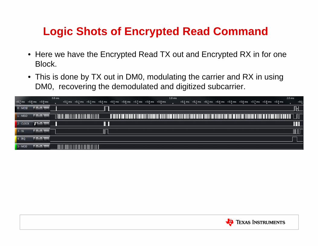
Logic Shots of Encrypted Read Command
• Here we have the Encrypted Read TX out and Encrypted RX in for one Block.
• This is done by TX out in DM0, modulating the carrier and RX in using DM0, recovering the demodulated and digitized subcarrier.

Logic Shots of Encrypted Read Response
• We have seen the TX out – here is the RX in response, zoomed – this is from reading a block of data.
• The encrypted bit stream response coming in from I/O_6 (normally MISO line during SPI operations) follows the ISO14443A standard.
• As the bits come in, they are timed (in 9.44uSec increments) and decoded, as Sequences D, E or F, then decrypted, all by the MCU.
• At the start we are measuring a Sequence D (logic 1) – but in this case it is also the tag response SOF.
D D E D D E
SOF
1 0 1 1 0 1 0 1 0 0 0 1 0 0 1 0
D E D E D EE E DE E
1
D
1
D
1
D
1
D
B 5 8 9 7

Using the GUI to do Encrypted Write Operations
• Here we are using the GUI to do encrypted read of Block 0 in Sector 1.
• Using Host Command Code 0xC800 + Data
• Below is entire sequence, zoomed out
• To the right is the GUI interface.

MIFARE Classic cards with 7 Byte UID’s • NXP has nearly run out of unique 4 byte UID’s for their MIFARE Classic
tags. This has caused them to recently release MIFARE Classic tags with Double size (7 Byte) UID’s. – Taken out of one of NXP’s App notes:
• It is very rare that you would ever encounter 4 byte tags with the same UID, but it is possible. NXP renamed the UID for this cards.
31

Handling Double Size UID• Here is the break down of the PICC’s response during anti-collision.
• We’ll need to understand this, to understand how to handle this in code.
32

Handling Double Size UID
• The Authentication procedure requires a 4 byte UID input.
• Table 4 defines which 4 bytes are used for 7 byte UID cards.
33

MIFARE Classic 7 byte UID Demo• 7 byte UID’s are not supporting in TI’s Mifare demo GUI.
• We currently have a Docklight project used for evaluation purposes.
34

Copy over UID from Scan for Card Response
35

Connect to COM port and step through commands.
36

Timing Observations with two different MCU platforms
• There are four main card operations to study for timings– Activation & Selection of the card (this is according to ISO14443A)– Authentication of the Card– Authenticated Read of a Block– Authenticated Read of a Sector
• Below here we can see a logic shot of activation and selection of the card, according to ISO144443-2, 3.
• Marker 1 is set at when we write the ISO Control Register for 0x88, marker 2 is set for end of the reception of the SAK and the RSSI value of the card.
• Total time using TRF79xxA + MSP430 is measured here as 2.1mSec (slides 45 & 46 from NXP public data, shows they are specifying taking up to 3mSec for this operation == we are on par / slightly better here.
37
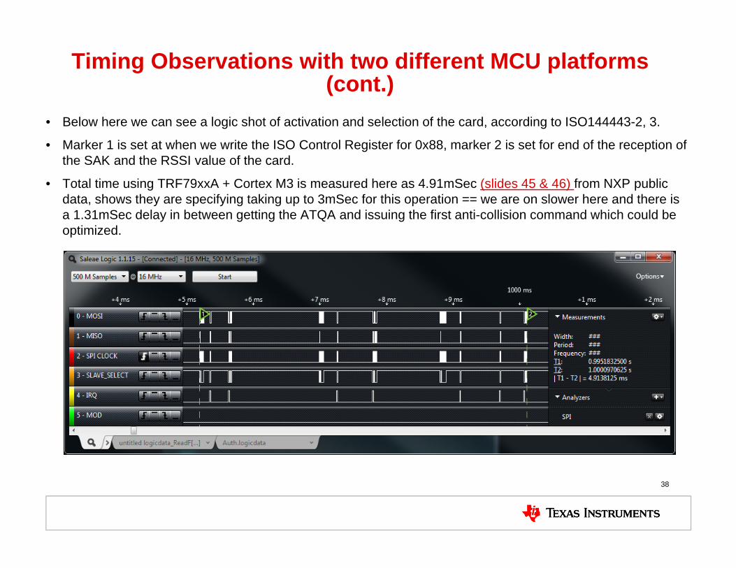
Timing Observations with two different MCU platforms (cont.)
• Below here we can see a logic shot of activation and selection of the card, according to ISO144443-2, 3.
• Marker 1 is set at when we write the ISO Control Register for 0x88, marker 2 is set for end of the reception of the SAK and the RSSI value of the card.
• Total time using TRF79xxA + Cortex M3 is measured here as 4.91mSec (slides 45 & 46) from NXP public data, shows they are specifying taking up to 3mSec for this operation == we are on slower here and there is a 1.31mSec delay in between getting the ATQA and issuing the first anti-collision command which could be optimized.
38

Authentication of the Card Timing• Authenticating the card is the next step after activation and selection.
• Here below one can see a logic shot which is showing performing the authentication process using the MSP430.
• Marker 1 is set for when the TRF79xxA is placed into Direct Mode 0 to begin the non-ISO standard mode of operation that Mifare Classic requires and Marker 2 is set for the end of that process.
• Total time measured is 151.26mSec NXP specs 2mSec for this.
• This could possibly be optimized (see next slide).
39

Authentication of the Card Timing• Authenticating the card is the next step after activation and selection.
• Here below one can see a logic shot which is showing performing the authentication process using the Cortex M.
• Marker 1 is set for when the TRF79xxA is placed into Direct Mode 0 to begin the non-ISO standard mode of operation that Mifare Classic requires and Marker 2 is set for the end of that process.
• Total time measured is 2.9mSec NXP specs 2mSec for this.
• This is doing in firmware close to what NXP is doing in hardware.
40
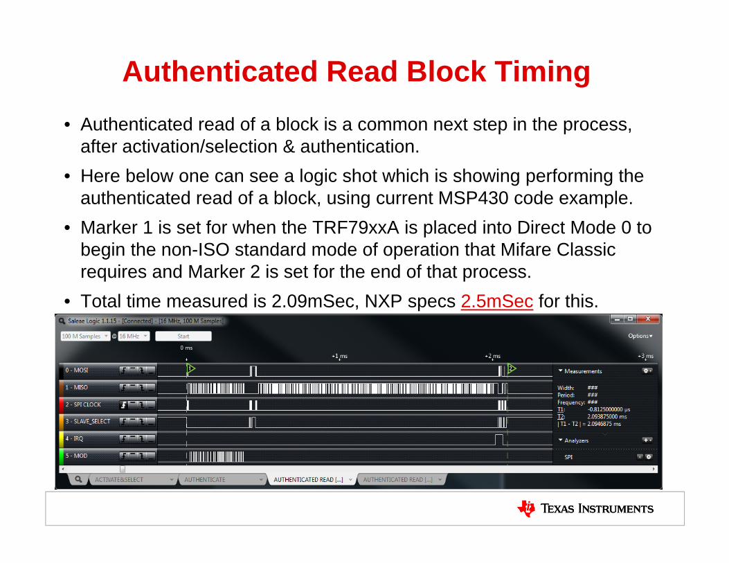
Authenticated Read Block Timing• Authenticated read of a block is a common next step in the process,
after activation/selection & authentication. • Here below one can see a logic shot which is showing performing the
authenticated read of a block, using current MSP430 code example. • Marker 1 is set for when the TRF79xxA is placed into Direct Mode 0 to
begin the non-ISO standard mode of operation that Mifare Classic requires and Marker 2 is set for the end of that process.
• Total time measured is 2.09mSec, NXP specs 2.5mSec for this.
41

Authenticated Read Block Timing• Authenticated read of a block is a common next step in the process,
after activation/selection & authentication. • Here below one can see a logic shot which is showing performing the
authenticated read of a block using current Cortex M code example. . • Marker 1 is set for when the TRF79xxA is placed into Direct Mode 0 to
begin the non-ISO standard mode of operation that Mifare Classic requires and Marker 2 is set for the end of that process.
• Total time measured is 5.07mSec, NXP specs 2.5mSec for this.
42
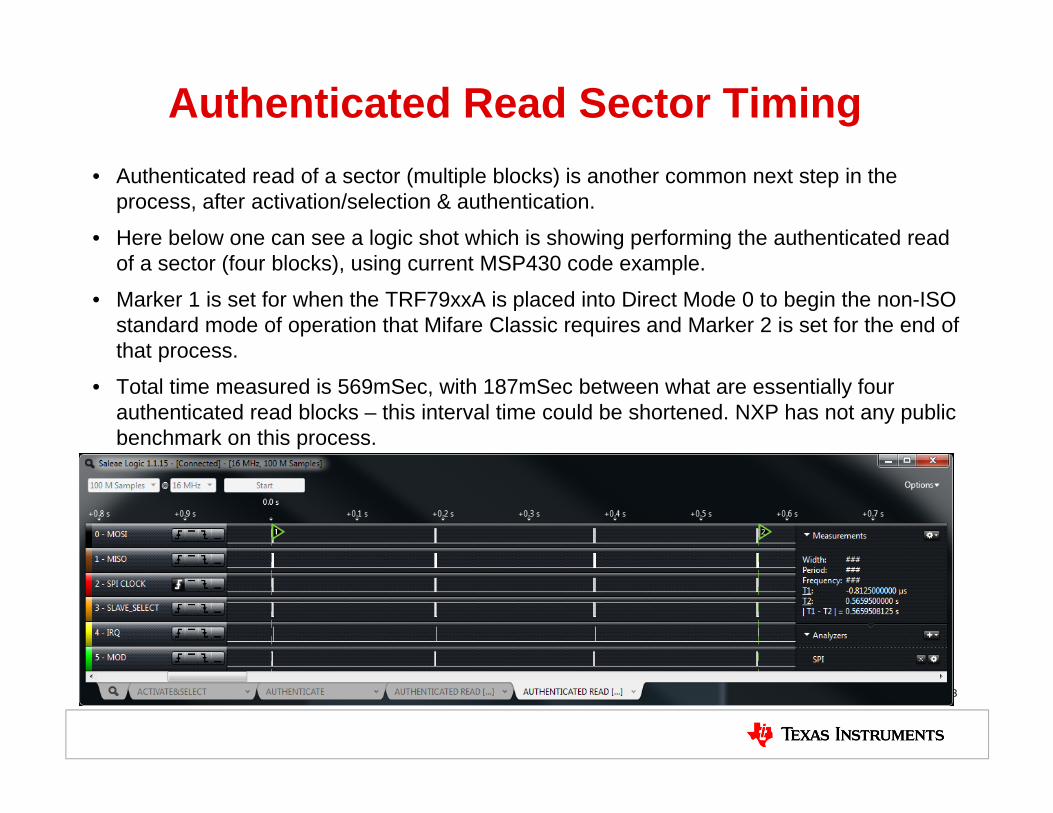
Authenticated Read Sector Timing• Authenticated read of a sector (multiple blocks) is another common next step in the
process, after activation/selection & authentication.
• Here below one can see a logic shot which is showing performing the authenticated read of a sector (four blocks), using current MSP430 code example.
• Marker 1 is set for when the TRF79xxA is placed into Direct Mode 0 to begin the non-ISO standard mode of operation that Mifare Classic requires and Marker 2 is set for the end of that process.
• Total time measured is 569mSec, with 187mSec between what are essentially four authenticated read blocks – this interval time could be shortened. NXP has not any public benchmark on this process.
43

Authenticated Read Sector Timing• Authenticated read of a sector (multiple blocks) is another common next step in the
process, after activation/selection & authentication.
• Here below one can see a logic shot which is showing performing the authenticated read of a sector (four blocks), using current Cortex M code example. .
• Marker 1 is set for when the TRF79xxA is placed into Direct Mode 0 to begin the non-ISO standard mode of operation that Mifare Classic requires and Marker 2 is set for the end of that process.
• Total time measured is 14mSec, with ~1mSec between what are essentially four authenticated read blocks – NXP has not any public benchmark on this process.
44
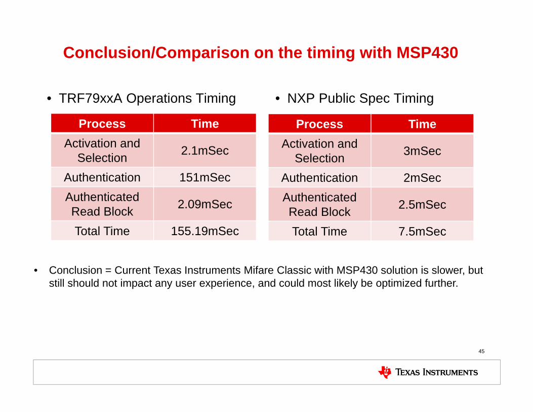
Conclusion/Comparison on the timing with MSP430
• TRF79xxA Operations Timing • NXP Public Spec Timing
45
Process TimeActivation and
Selection 2.1mSec
Authentication 151mSecAuthenticated Read Block 2.09mSec
Total Time 155.19mSec
Process TimeActivation and
Selection 3mSec
Authentication 2mSecAuthenticated Read Block 2.5mSec
Total Time 7.5mSec
• Conclusion = Current Texas Instruments Mifare Classic with MSP430 solution is slower, but still should not impact any user experience, and could most likely be optimized further.

Conclusion/Comparison on the timing with Cortex M
• TRF79xxA Operations Timing • NXP Public Spec Timing
46
Process TimeActivation and
Selection 4.91mSec
Authentication 2.9mSecAuthenticated Read Block 5.07mSec
Total Time 12.88mSec
Process TimeActivation and
Selection 3mSec
Authentication 2mSecAuthenticated Read Block 2.5mSec
Total Time 7.5mSec
• Conclusion = Current Texas Instruments Mifare Classic with Cortex M3 solution is slightyslower than what NXP is recommending, but should not impact any user experience!
Backup

EVM Screen Captures• These captures illustrate sequence X, as taken from the TRF7960EVM
tb = 9.44uSec tx = 4.72uSec t1 = 2.48uSec

EVM Screen Captures• These captures illustrate Sequences Y and Z, as taken from the TRF7960EVM
Sequence Y = Carrier for 9.44uSec Sequence Z = Pause for 2uSec-3uSec, Carrier for Remainder of 9.44uSec

EVM Screen Capture Decoded
1 or X 1 or X 0 or Y 0 or Z 0 or Z 1 or X 0 or Y 0 or Z 1 or X

Data from GUI for Mifare Authentication• 19:45:04.452 --> 010E000304C0FFFFFFFFFFFF0000• 19:45:04.749 <-- 010E000304C0FFFFFFFFFFFF0000• Crypto1 set key.• Initialization ok
• 19:45:04.812 --> 010F000304C160007EA6A6E29C0000• 19:45:05.015 <-- 010F000304C160007EA6A6E29C0000• Crypto1 authentication step 1.• Card nonce: D06530F3. Success
• 19:45:05.077 --> 010C000304C2112233440000• 19:45:05.312 <-- 010C000304C2112233440000• Crypto1 authentication step 2.• Authentication ok. Success