migration from cisco to hp switches - theseus
TRANSCRIPT

Qi Zhang
Migration from Cisco to HP switches
Technology and Communication
2010

1
VAASAN AMMATTIKORKEAKOULU
UNIVERSITY OF APPLIED SCIENCES
Degree Programme of Telecommunication Engineering
FOREWORD
The project's main job is to replace the switches; the most important part is the rational
allocation of VAMK VLAN, and the exchange of information security. The working
period is between Jan, 2010 and Apr, 2010.
I would like to express my appreciation to the supervisor Mr. Johan Dams, who has been
concerned about this project, guiding the project and giving me lots of help and
suggestions.
Then I would like to thank you to Dr. Smail Menani principal Lecturer to give me an
opportunity for this project.
Finally I would like to thank you to Mr. Hannu Teulahti Data Communications Planner
who guiding me to fully accomplish the configuration and support Academic and
theoretical of the project.
In Vaasa, 10 MAY 2010
Qi Zhang

2
VAASAN AMMATTIKORKEAKOULU
UNIVERSITY OF APPLIED SCIENCES
Degree Programme of Telecommunication Engineering
ABSTRACT
Author Qi Zhang
Title Migration from Cisco to HP Switches
Year 2010
Language English
Pages 42
Supervisor Johan Dams
In today's society, information has become a key structure resource. Network
technologies transmit accurate information, high-speed in all types of computers,
terminals, telephones, and fax machines and communications devices.
In campus, LAN technology is a relatively small geographical areas covered by
high-speed data network, which includes workstations, personal computers,
printers and other devices. It provides the equipments and applications, including
shared access, users to exchange files, e-mail and other communication
applications. VLAN technologies emerge and LAN switching technology is
inseparable. The project aim is to replace the switch, which VLAN conversion is a
very important part to distribute VLAN for helping the operator to manage easily.
On the other hand, VLAN considerably reduced the broadcasting field, and the
bandwidth of the application to the network information transmission rate greatly
increased, based on HP ProCurve switch 2910 series VLAN communication
protocol is IEEE802.1Q, through a combination of authentication and encryption
technology to ensure that the data in the whole network reliability and stability.
This paper is based on finding achieved by configuring layer 3 switch VLAN
allocation, implementation, and the connection between different switches,
ensuring information exchange, file transfer and telephone network, communicates
well in VAMK network.
Keywords LAN, IEEE802.1Q, VLAN, Switch

3
ABBREVIATION
LAN: Local Area Network
VLAN: Virtual Local Area Network
WLAN: Wireless LAN
NIC: Network Interface Card
MAC: Media Access Control
IPv4: Internet Protocol Version 4
IPv6: Internet Protocol Version 6
GARP: Generic Attribute Registration Protocol
GVRP: GARP VLAN Registration Protocol
RIP: Routing Information Protocol
SNTP: Simple Network Time Protocol
SNMP: Simple Network Management Protocol
LLDP: Link Layer Discovery Protocol
CDP: Cisco Discovery Protocol
ISL: Inter Switch Link (Cisco)
PDU: Protocol

4
Table of Contents FOREWORD .......................................................................................................... 1
ABSTRACT ............................................................................................................ 2
ABBREVIATION ................................................................................................... 3
1. INTRODUCTION ............................................................................................... 5
1.1. Motivation of project ................................................................................ 7
1.2. How the switch works ............................................................................... 8
2.TECHNICAL BACKGROUNDS ...................................................................... 11
2.1. Network Distribution ............................................................................. 11
2.2. Instruction of HP ProCurve Switch ....................................................... 12
2.3. Switch replacement procedure .............................................................. 12
2.3.1. Glossary ............................................................................................... 12
2.3.2. VLAN infrastructure ............................................................................ 13
2.3.3. GVRP introduction .............................................................................. 14
2.3.4. Switch replacement procedure ............................................................. 15
2.3.4.1. Sample topology .............................................................. 16
2.3.4.2. Preparations ...................................................................... 18
3.CONFIGURATION ON HP PROCURVE SWITCH ....................................... 25
3.1. Access HP ProCurve Switch ................................................................. 25
3.1.1. ProCurve Switch Command Prompts .................................................. 26
3.1.2. Getting help in the menu Interface ...................................................... 28
3.2. Basic Setting for the ProCurve Switch .................................................. 29
3.3. Configuration on HP ProCurve ............................................................. 31
3.3.1. Configuration Steps on HP ProCurve Switch ...................................... 31
3.3.2. Verification Commands On HP2910-wa033-1.................................... 36
3.4. Dynamic VLANs Implementation .......................................................... 37
3.4.1. GVRP configuration on HP ProCurve ................................................. 37
3.4.2. Verify Command of GVRP ................................................................. 40
4. CONCLUSION .................................................................................................. 42
REFERENCES ...................................................................................................... 43
APPENDIX 1 CISCO 3500 INTERFACE STATUS ........................................... 44
APPENDIX 2 CISCO 3500 VLAN STATUS ...................................................... 45
APPENDIX 3 HP2910-WA033-1 RUNNING-CONFIFURATION ................... 46

5
APPENDIX 4 HP2910-WA033-1 INTERFACE BRIEF ..................................... 49
APPENDIX 5 HP2910-WA033-1 OUTPUT OF LLDP ....................................... 50
APPENDIX 6 HP2910-WA033-1 VLANS .......................................................... 51
APPENDIX 7 GVRP_TEST_SW OUTPUT OF LLDP ....................................... 52
APPENDIX 8 HP-1 AND GVRP_TEST_SW VLANS ....................................... 53
APPENDIX 9 GVRP OUTPUT ........................................................................... 54
APPENDIX A LIST OF CONFIGURED HP PROCURVE SWITCHES ........... 55
APPENDIX B LIST OF CONFIGURED MSM422 ACCESS PONITS ............. 56

5
1. INTRODUCTION
LAN technologies are maturing technology enabling the computer to the network,
integration and rapid development of the direction of a growing number of local area
network interconnection between the requirements to achieve a wider range of data
communication and resource sharing. The interconnection technology is based on the
network structure into a clear functional level.
In VAMK the LAN system has multiple servers and several workstations together to
share the communication lines or through WLAN connection, they are in a limited
geographical scope of resource sharing and information exchange. Study of its
technical definition, it is through a specific type of transmission medium (such as cable,
fiber and wireless media) and network adapter (also called NIC) connected to the
computer and monitored by the network operating system network.
LAN has a higher data rate, error rate is relatively low, but the transmission distance is
restricted. And in the same LAN can be connected to a certain number of nodes is also
wanted.
Figure 1-1 shows a relatively common local area network, LAN has two parts of
network hardware and network software. Network hardware is: servers, workstations,
and network transmission medium and connecting components. Network software
includes network operating systems, network protocols, transmission control
information and the corresponding protocol software and a large number of network
application software.

6
Figure 1-1: Common LAN
Various servers in VAMK such as file server, print server, communications server,
database server and so on. File server is the most basic LAN server, for managing file
resources within the LAN, print server providing print services shared in the network
for users, communication server is mainly responsible for the local LAN and other
LAN, the host system or a remote workstation communication and database server is to
provide users with database retrieval, updates and other services.
Workstation (clients) generally is a user's computer also can be a dedicated computer.
Workstation has its own operating system, independent work, by running network
software can access the server shared resources in the workstations. VAMK
workstations include Windows7/Vista and Linux. Network connection between the
workstations and servers are achieved through the transmission medium components.
Network connection components include network interface cards, hubs and switches
etc. Here is our main target of this project: switch.
Switch is focus on the endpoint lines that connect and support the port number of
simultaneous connections between the workstation and achieve multiple simultaneous
data transfers between workstations, the bandwidth can be increased to improve the
local area network LAN Performance and service quality.

7
1.1. Motivation of project
Remove the Cisco switches and replaced with HP ProCurve switch, because Cisco
service ended, VAMK adopt the new network hardware of HP 2910al ProCurve
Switch that need to converse VLANs on HP. For settings because Cisco switches
have many useless VLANs, therefore using the new VLANs to manage, facilitate
management. All the 2910 switches have four dual-personality Gig ports and four
optional 10G port with one RJ-45 serial console port. The development of IPv6 has
become a trend; 2910al series is support dual stack of IPv4/IPv6 which provides
transition mechanism from IPv4 to IPv6; both protocols connectivity is supported, of
course HP ProCurve can be managed and deployed at the edge of IPv6 networks, so
far we still use IPv4 in VAMK, but Physical Devices are prepared for the future.
Summarized below are some of the advantages about HP ProCurve Switch:
Connectivity
10Gbps Ethernet connectivity – support four optional and flexible 10G-Gigbit
ports.
Dual stack (IPv4/IPv6) – provides transition mechanism from IPv4 to IPv6,
the switches also can be supported and managed IPv6 network.
Manageability ̈
RMON (Remote Network Monitoring) – provide advanced monitoring and
reporting capabilities for history, status and events.
Command authorization – provide CLI (Command Line Interface) to
individual network administrator’s login.
Layer 2 switching
VLAN support and tagging – supports the IEEE 802.1Q about 4,094 VLAN
IDs and 256 VLANs simultaneously.
Layer 3 routing
Static IP Routing – provides manually configured routing.
RIP – provides RIPv1 and RIPv2 routing.

8
Security
IEEE 802.1X – support multiple user authentications with RADIUS server.
Warranty and support
ProCurve Warranty – for as long as you own the product, with
next-business-day advance replacement
We need to refer the previous Cisco configuration, also need to understand the
distribution of the switches in the VAMK. Focus on new VLANs conversion on HP
ProCurve switches configuration and replace of the Cisco switches. Understand the HP
switch description with functions that what the difference settings are between HP and
CISCO.
HP ProCurve Identity Driven Manager is to manage the HP switches and other HP
devices while the new devices are added, it automatically detects and manually assign
switch to the specified group.
Upon completion of the switch assembly, assign wireless access point static DHCP
address in ns2.puv.fi server.
1.2. How the switch works
Switch technology based on layer 2 (data link layer) technologies, is the data link
equipment, data packets can be identified in the MAC address information, according
to MAC address forwarding MAC address information, record MAC address and port
corresponding to an address in the internal address table.
1. Switch receive a data packet from one port, first read the header of the source MAC
address, MAC address it’s know that the machine connect to which port.
2. Reads the header of the head to destination MAC address and find the appropriate

9
port in the address table.
3. If appropriate port can be found in destination MAC address then copy the data to
this port.
4 If the table cannot found in the corresponding port put the data packet broadcast to all
ports, when the destination machine respond to the source machine, the switch can
learn which destination MAC address and port corresponding to transmit data, no
longer need to carry out all ports broadcast t next time.
Layer 3 (network layer) switches is a part of the router functions of the switches, the
most important objective is to accelerate the exchange of data within a large local area
network, and the routing function has also the services for this purpose can be a route,
forward many times. Such regularity for the data packet forwarding process to achieve
high speed by the hardware, but as the routing information update, routing table
maintenance, route calculation, routing and other functions determined by the software.
Consideration of security and convenience, mainly purpose to reduce the broadcast
storm, such as large local area network (LAN) by function or geographical factors
divided into a small local area network, making the VLAN in the network to a large
number of applications, communication between different VLAN must be forwarded
through the router to complete. Because network visits information is increase, simply
use a router to achieve the access, for the limited number of ports and limiting the size
of the network and access speed. Based on this situation come into being layer 3
switches - designed for the IP, simple interface type, with a strong layer 2 packet
processing capabilities, is ideal for large LAN routing and switching of data, It can
work on layer 3 protocol or part of the complete replacement of traditional router
functions, while the rate of exchange has almost the same with layer 2 switch, and the
price is relatively cheaper.

10
In campus, the general will use layer 3 switches in the network of core layer, with the
gigabit ports or fast port connection different subnet or VLAN. The most important
function of layer 3switch is to speed up data exchange within a large local area network,
the routing function has also many purposes around the launch, so its routing
capabilities of professional grade is a little less than router. After all, security, protocol
support has gaps, can not completely instead of routers.
In practical applications, the typical approach is: The LAN has the same subnet of the
Internet and VLAN, use layer 3 switches instead of the routers, LAN and public
network only to achieve inter-connectivity for area network accesses, that’s we need
professional router.

11
2. TECHNICAL BACKGROUNDS
2.1. Network Distribution
VAMK university network provides a comprehensive application environment for the
school's teaching, management, office, and information exchange, communication
network.
Figure 2-1: VAMK current network topology
Figure 2-1shows VAMK current Network topology is star topology has three layers that
consists of core layer, distribution layer and access layer. Core layer provides optimal
transport between two locations, the distribution layer of the network service to connect
to the access layer, and the realization of security, communications loading and routing
strategy. Access layer provides users access to a switch or hub.
Software and hardware that contains operation system, various servers and backbone
switch; central/router switch; main building switch and access switch.

12
Object of the project access switches are control network of the classrooms and staff
offices. We focus on Access Layer in the project to remove Cisco replaced with HP.
2.2. Instruction of HP ProCurve Switch
In the project we use HP ProCurve 2910al Switch Series includes:
a) HP ProCurve 2910al-24G Switch
b) HP ProCurve 2910al-48G Switch
All 2910 switches have four dual-personality Gig ports and four optional 10G port with
one RJ-45 serial console port. The development of IPv6 has become a trend; 2910al
series is support dual stack of IPv4/IPv6 which provides transition mechanism from
IPv4 to IPv6; both protocols connectivity is supported, of course HP ProCurve can be
managed and deployed at the edge of IPv6 networks, so far we still use IPv4 in VAMK,
but Physical Devices are prepared for the future.
2.3. Switch replacement procedure
2.3.1. Glossary
Figure 2-2 shows deals with what different command to set uplink port in VLAN
between HP and Cisco, these are used to describe similar concept on both platforms.

13
Figure 2-2: Difference commands between Cisco & HP
2.3.2. VLAN infrastructure
Virtual Local Area Network uses to segment the network into smaller broadcast domain
or segments. When the device is actually located a number of different LAN segments,
they can be as connected to the same physical media to communicate. VLAN is based
on the logical connection rather than a physical connection, so it is very flexible.
VLAN classification has many ways - IP address-based VLANs, Port-based VLANs,
MAC-based VLANs etc.; the specific classification can be selected according to the
actual situation of the division of different ways. In our college VLAN conversion
divided by Port-based. Here are some advantages of port-based VLANs.
Port-based VLANs is a common method of VLAN classification also called
segment-based VLANs or static VLANs; a lot of switch products support this function.
This method is based on the Ethernet switch ports division.
It divided into single-port VLANs switch port and multi-switch port VLANs
classification, the former supports only a single switch port number specified on the
composition of the VLAN, in a multi-division can make a VLAN spans multiple
switches, and the same switch port can belong to different VLAN. Port-based VLANs

14
classification can be better for users to manage and reduce broadcast storms, and high
security.
Advantage is simple to define VLAN membership as all the ports are defined for the
same VLAN group. It’s suitable for any network. If a user leaves the original port, to a
new switch the port will be redefined.
In the project Cisco switches remove many kind of useless VLANs and the project
provide new VLAN 316 in HP ProCurve Switches instead of VLAN 29(manage Cisco
switch); therefore converse VLAN is an important part of this project.
Figure 2-3 shows VAMK Important VLANs
Figure 2-3: VAMK important VLAN List
2.3.3. GVRP introduction
GVRP is an application of GARP, based on the working mechanism of GARP,
maintaining the switch in the VLAN dynamic registration information and disseminate
this information to other switches. Support GVRP feature of the switch can receive the
VLAN information from other switches, and dynamically update the local VLAN
registration information, including the current VLAN membership, the members of
these VLAN ports through which to reach and so on.
Name Duty
VLAN 316 Manage HP ProCurve Switch
VLAN 329 Manage HP Access Point (MSM422 wireless device)
VLAN 306 Filter PCWN wireless
VLAN 332 VAMK Staff
VLAN 396 VAMK Student
VLAN 397 VAMK Mobile
VLAN 317 Telephone system and work time management
VLAN 305 PCWN (wireless network)
VLAN 29 Manage Cisco Switch

15
GVRP is IEEE GARP-based protocol developed.
GVRP protocol is by attribute statement - a registration mechanism to the local VLAN
information notice to the other switch.
GVRP protocol supported VLAN ID range of 1-4094.
2.3.4. Switch replacement procedure
Compared with other hardware, switch is not really particularly stable and reliable
equipment. So there will be a variety of problems occur, we need to replace the switch.
If there is no manual, we can change it down, and thereafter on demand, re-configure
and use it. However, if based on reasonable steps that can save administrators a lot of
time to achieve the multiplier effect. Now we're going to explore a set of replacement
switches reasonable steps to.
1. Remove Cisco switch
a) Archive backup before remove the Cisco switch we need to save its
configuration;
b) Mark the labels on the connect switch cables and record each corresponding
switch port;
c) Shutdown, power off and unplug all the connecting cables;
d) Remove the switch out of Cabinet
2 Install HP ProCurve Switch
a) Configure HP Switch;
b) Put HP switch in cabinet;
c) In accordance with the original line corresponds to the original plan plugged;
d) Test connection
16
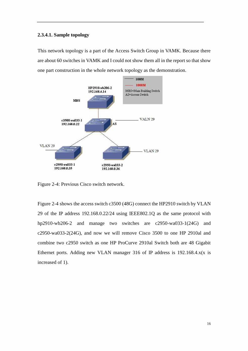
2.3.4.1. Sample topology
This network topology is a part of the Access Switch Group in VAMK. Because there
are about 60 switches in VAMK and I could not show them all in the report so that show
one part construction in the whole network topology as the demonstration.
Figure 2-4: Previous Cisco switch network.
Figure 2-4 shows the access switch c3500 (48G) connect the HP2910 switch by VLAN
29 of the IP address 192.168.0.22/24 using IEEE802.1Q as the same protocol with
hp2910-wb206-2 and manage two switches are c2950-wa033-1(24G) and
c2950-wa033-2(24G), and now we will remove Cisco 3500 to one HP 2910al and
combine two c2950 switch as one HP ProCurve 2910al Switch both are 48 Gigabit
Ethernet ports. Adding new VLAN manager 316 of IP address is 192.168.4.x(x is
increased of 1).
17
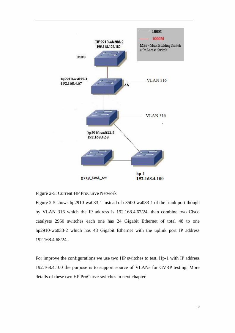
Figure 2-5: Current HP ProCurve Network
Figure 2-5 shows hp2910-wa033-1 instead of c3500-wa033-1 of the trunk port though
by VLAN 316 which the IP address is 192.168.4.67/24, then combine two Cisco
catalysts 2950 switches each one has 24 Gigabit Ethernet of total 48 to one
hp2910-wa033-2 which has 48 Gigabit Ethernet with the uplink port IP address
192.168.4.68/24 .
For improve the configurations we use two HP switches to test. Hp-1 with IP address
192.168.4.100 the purpose is to support source of VLANs for GVRP testing. More
details of these two HP ProCurve switches in next chapter.

18
2.3.4.2. Preparations
Before configuration on HP ProCurve Switch, there are various preparations we need
to know that make sure all VLANs information such as status, name and the
corresponding port and how many VLANs will be assigned etc. The preparation can
affect the configuration so that make clear several forms to record the previous
settings on Cisco and new settings on HP ProCurve. Refer to those forms,
Discovery configuration
Regarding discovery protocol on Cisco configuration, CDP is enabled by default,
ProCurve LLDP is also enabled in send and receive mode. Link Layer Discovery
Protocol can directly display network devices for advertising of their identity,
capabilities and interconnecting. Very useful protocol used in HP Switch.
Checking Discovery info on Cisco Switch
On Cisco 3500-wa033-1:
Figure 2-6 shows c3500-wa033-1 Cisco Discovery Protocol result, configuration
commands “show cdp neighbours “list CDP neighbour devices. As expected, it displays
the two Catalysts 2950. Cisco 3500 local interface Gig0/48 is connect to
c2950-wa033-1 port of Gig0/24, the other one Gig0/47 is connect to wa033-2 port of
Gig0/24.
Figure 2-6: Cisco Discovery Protocol
Checking running-configuration
Take a cut out of the c3500 running/configuration, the Cisco Switch manage VLAN 29

19
IP address 192.168.0.22/24.
c3500-wa033-1#show running-config
interface VLAN29
ip address 192.168.0.22 255.255.255.0
no ip directed-broadcast
no ip route-cache
Checking interface status
On Cisco 3500:
Firstly get trunk ports information of interface line status is required to pass VLAN
information between switches. Cisco switch have two Ethernet trunk mechanisms: ISL
and IEEE 802.1Q.
Both ISL and IEEE 802.1Q are supported on Cisco 3500, but Cisco 2950 only support
802.1Q. HP ProCurve 2910al series as the same with Cisco 2950 can support 802.1Q.
ISL and IEEE802.1Q they belong to different protocol, cannot communicate each
other.
How the two protocols additional VLAN information on the data frame?
ISL (Inter Switch Link):
ISL, Cisco product support the similar with IEEE802.1Q, used to link aggregation on
the additional protocol VLAN.
After using the ISL, the head of each data frame of 26 bytes will be added "ISL header
(ISL Header)", and bring the end of the frame header by including the ISL frame
including the data calculated by 4 bytes CRC value. In other words, totally increase of
30 bytes of information.
Use ISL method, when the data frame leaves the link aggregation; simply remove the
ISL header and the new CRC. As the original frame and CRC are intact, so do not need

20
to recalculate the CRC.
Figure 2-7: ISL Frame
Figure 2-7 shows ISL Frame, ISL header and new CRC package the original data frame,
therefore it calls “Encapsulated VLAN”.
IEEE 802.1Q
IEEE802.1Q is certified through the IEEE additional VLAN on the data frame
identification information of the agreement.
IEEE802.1Q attached to the VLAN identification information in the data frame “source
MAC address" and "Category Domain (Type Field)" between. Include 2 bytes TPID
and 2 bytes TCI, a total of 4 bytes.
Added in the data frame the content of 4 bytes, then the CRC value must change.
Currently CRC frame value obtained is re-calculated the data frame after inserted TPID
and TCI.

21
Figure 2-8: IEEE 802.1Q frame
Figure 2-8 shows IEEE802.1.Q frame, when the data frame leaves link aggregation,
TPID and TCI will be removed, then will conduct a CRC re-calculation.
TPID value fixed at 0x8100. Switch by TPID, to determine the additional data frame's
VLAN information based on IEEE802.1Q. The essence of the VLAN ID is TCI's 12-bit.
So that up to 212
=4096 identified VLAN.
VLAN-based IEEE802.1Q additional information, as in the delivery label attached
articles. Therefore, it is also known as "tag-based VLAN (Tagging VLAN)".
Figure 2-9 shows Cisco 3500 interface status, the command “show interface status”
was captured (Appendix 1), according interfaces status we know.
Catalysts 3500
Port Name VLAN 29
Fa0/42 alpha.cc.puv.fi Trunk to alpha.cc.puv.fi
Fa0/47 c2950-wa033-1 Trunk to wa033-1 switch

22
Figure 2-9: Catalysts 3500 interface status
Figure 2-10 shows Cisco 2950 Switches interface status, use the same method get
c2950-wa033-1 and wa033-2 interface status:
Figure 2-10: Catalysts 2950 interface status
Checking VLANs
The command “show vlan status” was captured (Appendix 2).Get the current VLANs
information. Remove useless VLANs on Cisco 3500. Choose active VLANs and write
in the form.
Figure 2-11 shows Cisco 3500 VLAN, for example, VLAN 320 has the name Printers
which is active with a port number Fa0/37 but for VLAN 367 has the port number Fa0/1
to Fa0/16, Fa0/18 to Fa0/36, Fa0/38 to Fa0/41, Fa0/43 and Fa0/44, according VLAN
status, current VLANs are used:
Figure 2-11: Catalysts 3500 VLAN
Figure 2-12 shows Catalysts 2950 switch VLAN.
Fa0/48 c2950-wa033-2 Trunk to wa033-2 swtich
Gi0/1 hp2910-wb206-2 Trunk to wb206-2 switch
Catalysts 2950 wa033-1
Port Name VLAN 29
Fa0/24 c3500-wa033-1 Trunk to c3500-wa033-1
Catalysts 2950 wa033-2
Fa0/24 c3500-wa033-1 Trunk to c3500-wa033-1
Catalysts 3500
VLAN name Status Ports
VLAN320 Printer Active Fa0/37
VLAN363 Etaliittymat Active Fa0/45,46
VLAN367 Active Fa0/1 – 16, 18–36, 38–41,
43 and 44
Catalysts 2950-wa033-1

23
Figure 2-12: Catalysts 2950 VLAN
To sum up Catalysts 3500 and two Catalysts 2950 VLANs are keeping in the HP
ProCurve that those VLANs information will be assigned in HP switch, therefore the
interface also should be rearranged in HP Switch. Because reasonable distributions of
ports help improve future management, administrators can easily view the switch port
information.
Rearrange c3500-wa033-1 to hp2910-wa033-1
Figure 2-13 and 2-14 shows rearrange trunk port and interfaces from Cisco 3500 to
HP 2910, distribute the trunk port on hp 2910-wa33-1; replace VLAN 29 with VLAN
316 assign on Fa0/46, 47 and 48 ports. VLAN 320 on Fa0/1 port,
Figure 2-13: Rearrange trunk port on Catalysts 3500
VLAN name Status Ports
VLAN367 Active Fa0/1 – 19
VLAN317 Active Fa0/20 – 23
Catalysts 2950-wa033-2
VLAN367 Active Fa0/1 – 9, 11 – 22
VLAN320 Active Fa0/10
VLAN317 Active Fa0/23
c3500-wa033-1 uplink port assign hp2910-wa033-1 uplink port assign
Trunk
port
Name VLAN Trunk
port
Nam VLAN
Fa0/42 alpha.cc.puv.fi VLAN
29
Fa0/46 alpha.cc.puv.fi VLAN
316
Fa0/47 c2950-wa033-1 VLAN
29
Fa0/47 hp2910-wa033-2 VLAN
316
Fa0/48 c2950-wa033-2 VLAN
29
Gi0/1 hp2910-wb206-2 VLAN
29
Gi0/48 Hp2910-wb206-2 VLAN
316
c3500-wa033-1 interfaces assign hp2910-wa033-1 interfaces assign
Port Name VLAN Port Name VLAN
Fa0/1 – 16,
18 – 36, 38 -
VLAN 367 Fa/4 - 44 VLAN 367

24
Figure 2-14: Rearrange interface on Catalysts 3500
Rearrange interfaces and combine two c2950 into one hp2910-wa033-2
Figure 2-15 and 2-16 shows rearrange trunk port and interfaces on Cisco 2950.
Figure 2-15: Rearrange trunk port on Catalysts 3500
Figure 2-16: Rearrange interface on hp2910
41
Fa0/37 Printer VLAN 320 Fa 0/1 Printer VLAN 320
Fa0/45 Etayhteys
Jakas/Kallio
VLAN 363 Fa0/2 Etayhteys
Jakas/Kallio
VLAN 363
Fa0/46 Borje Harju VLAN 363 Fa0/3 Borje Harju VLAN 363
c2950-wa033-1 uplink port assign hp2910-wa033-2 uplink port assign
Trunk Port Name VLAN Trunk port Name VLAN
Fa0/24 c3500-wa033-1 VLAN 29
Fa0/48
hp2910-wa033-1
VLAN
316
c2950-wa033-2 uplink port assign
Fa0/24 c3500-wa033-1 VLAN 29
c2950-wa033-1 interfaces assign
Port Name VLAN
Fa0/1 – 19 VLAN
367
Fa0/20–23 Telephone system VLAN
317
c2950-wa033-2 interfaces assign
Fa0/1 – 9,
11 – 22
VLAN
367
Fa0/10 Printer VLAN
320
Fa0/23 Telephone system VLAN
317
hp2910-wa033-2 interfaces assign
Port Name VLAN
Fa0/1 – 5 Telephone system VLAN
317
Fa0/6 Printer VLAN
320
Fa0/7– 47 VLAN
367

25
3. CONFIGURATION ON HP PROCURVE SWITCH
3.1. Access HP ProCurve Switch
Switch without the keyboard and mouse, no monitor, the computer needs to initialize
the switch and the switch console serial port to connect. Two most common approaches
is to use the console cable (control cable) to connect PC and use telnet to access
Equipments and Hardware:
HP ProCurve Switch
RJ-45 to DB9 Adapter
Software:
HyperTerminal
Putty
HP ProCurve RJ45-DB9 driver
Figure 3-1 shows use a RJ-45 to DB9 adapter to connect the switch console port and
laptop COM 1 port.
Figure 3-1: Connection Diagram
Normally switch of the default state is bps – bits per second is 96000bps, the COM
port of properties is set to revert to the default value which you can choose to identify
and press enter key, then the screen prompt appears on the router or other characters,

26
indicating the computer is connected to the switch, and wait for the switch begins to
load IOS (Internet work Operating System) while loading IOS system you can see the
IOS version, switch type and memory size are displayed, after the completion can be
configured.
Setting communication parameters on HyperTerminal
COM port COM1
9600bps
Data bits: 8
Parity: None
Stop bits: 1
Flow control: None
3.1.1. ProCurve Switch Command Prompts
In the default configuration, switch displays the following CLI prompts.
Figure 3-2 shows login flow chart of process model.
User Exec
Log in to start switch HP ProCurve Switch>
Privileged Exec
User mode “enable” command execution HP ProCurve Switch#
Global Configuration
Privileged mode “configuration” execution HP ProCurve Switch(config)#
Config-VLAN (Global Configuration VLAN mode)
Global mode “vlan-id” execution HP ProCurve Switch(vlan-id)#

27
Interface configuration level (Global Configuration interface level mode)
Global mode “interface-id” execution HP ProCurve Switch(eth-id)#
Figure 3-2: Login flow chart
Figure 3-3 shows logout flow chart of process model.
User Exec
HP ProCurve Switch> Execution “exit” command
Privileged Exec
HP ProCurve Switch# Execution “logout” or “exit” command
Global Configuration
HP ProCurve Switch(config)# Execution “exit” or ctrl+Z command
Config-VLAN (Global Configuration VLAN mode)

28
HP ProCurve Switch(vlan-id)# Execution “exit” or ctrl+Z command
Interface configuration level (Global Configuration interface level mode)
HP ProCurve Switch(eth-id)# Execution “exit” or ctrl+Z command
Figure 3-3: Logout flow chart
3.1.2. Getting help in the menu Interface
For information on specific parameters in the menu interface, help command conduce
to configure the switch when you have no idea or forget the command, mention the
information you need, and suggestion the processing in future.
Otherwise the command “help” in the CLI has the similar function with help in the
menu interface, type “help” in the privilege execution while several commands are
displayed on your switch. Get the help from the list that improve your configuration.

29
3.2. Basic Setting for the ProCurve Switch
All HP ProCurve Switches have the same basic settings, such as SNTP, SNMP and IP
route parameters must be the same, because data transmission though by these server
and gateway. The theory of layer 3 switches sending data between different
computers:
Figure 3-4: Switch sends data between two computers
Figure 3-4 shows switch send data between two computers, such as A send data to B,
the requirement is known destination IP address of B, then A estimate and check
destination IP address whether or not in the same subnet mask.
If A and B are in the same network segment, but do not know the MAC address required
for forwarding of data, A will send an ARP (Address Resolution Protocol) request, B
return to their MAC address, A package this MAC and send the packet switch, the
switch use the layer 2 (data link layer) function, find the MAC address table, will
forward the packet to the appropriate port.
If the destination IP address displayed is not in the same network segment, achieve the
communication between A and B, no corresponding MAC address table entry in the
flow cache, firstly to send a normal data packet to a default gateway, the default
gateway in the operating system has been set up, corresponding to the routing module
of layer 3 (network layer), we can see that the data which is not the same subnet, the
first the default gateway of MAC address is kept in the MAC; then routing modules

30
receiving this packet, check the routing table to determine the route to reach B, it will
construct a new frame header, in which the default gateway MAC address as the source
MAC address, host B's MAC address for the destination of MAC addresses.
Recognition by some trigger mechanism, the establishment of the host A and B's MAC
address and corresponding port forwarding System, and record it in the flow cache,
after the A to B data, directly referred to the layer 2 of the exchange module to
complete.
Configuration include-credentials have to be given once by hand before copy paste this
setting uses on every HP ProCurve Switch. The project requirements use the last port as
uplink port (24G/48G).
include-credentials
time timezone 120
time daylight-time-rule Western-Europe
ip routing
timesync sntp
sntp unicast
sntp server priority 1 192.168.1.1 3
sntp server priority 2 192.168.1.2 3
ip ssh
ip ssh filetransfer
ip route 0.0.0.0 0.0.0.0 192.168.4.1
router rip
no auto-summary
exit
snmp-server community "public" unrestricted
snmp-server host 193.166.140.174 "public"
snmp-server host 193.166.140.44 "public"
Time zone 120: Europe time zone.
IP routing: access the path of the data travel across multiple networks.
SNTP server priority 1 192.168.1.1: switch achieves time synchronization with SNTP
server.
IP authorized-managers: show IPv4 address allowed managing the switch.

31
IP route 0.0.0.0 0.0.0.0 192.168.4.1: configure default route which means 0.0.0.0
0.0.0.0 indicate all of the local IP address (first 0.0.0.0 is all IPs; second is all subnets),
192.168.4.1 indicate the next hop switch is 192.168.4.1.
SNMP server host 193.166.140.174 "public: SNMP agent sent trap to host
193.166.140.174 that can grantee communication of the switches.
The setup configuration steps:
Step 1: Access Global Configuration HP2910# configure terminal
Step 2: Give include-credentials HP2910(config)# include-credentials
Step 3: copy and paste the basic configuration before settings
3.3. Configuration on HP ProCurve
3.3.1. Configuration Steps on HP ProCurve Switch
Refer to figure from 2-10 to 2-13, the interface are assigned on HP ProCurve.
This configuration example applies to the following HP series 2910 switch products.

32
Figure 3-5: Network connection
Figure 3-5 shows the network connection according Figure 2-5,trunk port 22 of
hp2910-wb206-2 connect to wa033-1 Gigabit port 48, on wa033-1 port 45 is untagged
for a wireless access point connect to Ethernet 0, besides port 45 need to be tagged on
trunk port (47 and 48), then port 47 as the trunk port connect to the next one wa033-2
switch on port 48, hp-1 with port 48 trunk to port 29 on wa033-2, the other one
802.1x-test port 47 trunk to port 22 on wa033-2.
Now we get all trunk port information, configure VLAN 316 (192.168.4.47) on
hp2910-wa033-1, VLAN 316 uses on uplink port, the duty is to carry multiple VLANs.
The next steps all VLANs have to tagged on VLAN 316, it decide VLANs where from
and go.

33
hp2910-wa033-1
1. Configure Host Name
In VAMK, there are various switches, each switch in the network as a certain role;
administrators face the problems when making management of the large number of
different types of switches. Therefore, a meaningful name to the switch to show its type,
function and location (wa033 classroom) is necessary.
HP ProCurve Switch(config)# hostname hp2910-wa033-1
2. Configure Password
Set user password when the user need remote login or directly connect to console port
with switch, we can set the operator and manager password. In our situation we are
using the same password on each ProCurve Switch.
hp2910-wa033-1(config)# password operator xxxx
hp2910-wa033-1(config)# password manager xxxx
3. VLAN creation
Access vlan-id execution in global configuration; create VLAN 316, give an IP
address and subnet mask address to this VLAN, setting port 46 to 48 are trunk ports that
47 trunk to upper switch wa033-2 and 48 to wb206-2.
hp2910-wa033-1 (config)# VLAN 316
hp2910-wa033-1 (VLAN-316)# name KYTKIMET
hp2910-wa033-1 (VLAN-316)# ip address 192.168.4.67/24
hp2910-wa033-1 (VLAN-316)# tagged 46-48
hp2910-wa033-1 (VLAN-316)# exit
Printer VLAN 320 uses port 1 which is connecting to the printer in classroom wa033 as
untagged status; port 2 and 3 are assigned to VLAN 363; ports 4 to 44 are assigned to
VLAN 367 that manage all students computer in wa033. Uplink ports in each VLAN
must be tagged on VLAN 316. All data communication exchanges though the main
VLAN 316.

34
hp2910-wa033-1(config)# VLAN 320
hp2910-wa033-1(VLAN-320)# name PRINTERS
hp2910-wa033-1(VLAN-320)# untagged 1
hp2910-wa033-1(VLAN-320)# tagged 46-48
hp2910-wa033-1(VLAN-320)# exit
hp2910-wa033-1(config)# VLAN 363
hp2910-wa033-1(VLAN-363)# name SDSL-LIITTYM
hp2910-wa033-1(VLAN-363)# untagged 2-3
hp2910-wa033-1(VLAN-363)# tagged 46-48
hp2910-wa033-1(VLAN-363)# exit
hp2910-wa033-1(config)# VLAN 367
hp2910-wa033-1(VLAN-367)# name VLAN367
hp2910-wa033-1(VLAN-367)# untagged 4-44
hp2910-wa033-1(VLAN-367)# tagged 46-48
hp2910-wa033-1(VLAN-367)# exit
VLAN 320, 363 and 367 already tagged on VLAN 316 then follow the IP address of
VLAN 316 (192.168.4.67); VLANs are recorded in NS (Name server) server which is
used to specify the DNS server from the domain name for resolution, it will get the
request from switch to and checks that VLAN information whether exist and offer an IP
address to the computer. For example printer VLAN 320 will get the IP address
192.168.20.xxx.
VAMK internal telephone system VLAN is 317, it, and here we did not configure
VLAN 317 in hp2910-wa033-1, this VLAN also has to be tagged in VLAN 316 for
access VLAN 317 data transmission through by VLAN 316, the purpose is for wa033-2
switch can take the VLAN 317 information from the uplink port.
hp2910-wa033-1(config)# VLAN 317
hp2910-wa033-1(VLAN-317)# name VLAN317
hp2910-wa033-1(VLAN-317)# tagged 46-48
hp2910-wa033-1(VLAN-317)# exit
Assign wireless network VLAN 329 with another four VLANs 306, 332, 396 and 397
which I mentioned in the figure 2-3 VAMK important VLAN list. VLAN 329 is like
VLAN 316, 329 control all wireless devices, and the duty of 316 is to manage wired
devices.

35
hp2910-wa033-1(config)# VLAN 329
hp2910-wa033-1(VLAN-329)# name HP-WLAN
hp2910-wa033-1(VLAN-329)# untagged 45
hp2910-wa033-1(VLAN-329)# tagged 48
hp2910-wa033-1(VLAN-329)# exit
hp2910-wa033-1(config)# VLAN 306
hp2910-wa033-1(VLAN-306)# name PCWN
hp2910-wa033-1(VLAN-306)# tagged 48
hp2910-wa033-1(VLAN-306)# exit
hp2910-wa033-1(config)# VLAN 332
hp2910-wa033-1(VLAN-332)# name W30-STAFF
hp2910-wa033-1(VLAN-332)# tagged 45,48
hp2910-wa033-1(VLAN-332)# exit
hp2910-wa033-1(config)# VLAN 396
hp2910-wa033-1(VLAN-396)# name WL-Vamk-w30
hp2910-wa033-1(VLAN-396)# tagged 45,48
hp2910-wa033-1(VLAN-396)# exit
hp2910-wa033-1(config)# VLAN 397
hp2910-wa033-1(VLAN-397)# name WL-VamkMobile
hp2910-wa033-1(VLAN-397)# tagged 45,48
hp2910-wa033-1(VLAN-397)# exit
Assign VLAN 329 static DHCP address 192.168.29.21 in ns2 server (ns2.puv.fi),
Hardware Ethernet is MAC address of MSM422 Access point. Switch loading VLAN
329 parameters in ns2 server and assign the static DHCP address to HP Access Point.
1) Login ns2.puv.fi by SSH in putty
2) Become root sudo –i
3) Find the location of dhcp3 folder; cd /etc/dhcp3/
4) Nano master.dhcp.conf and edit configuration as below:
host puv-wa033 {
hardware ethernet 00:0f:61:0e:2b:b2;
fixed-address 192.168.29.21;
}
4. Authorized IP manager
The security configuration by authorized IP Manages function used IP address and
masks to determine which stations (PCs or workstations) can access the switch through

36
the network. The default IP Mask is 255.255.255.255 which means allow switch access
only a station having an IP address, the Mask address specify ranges of the IP address.
The function of authorized IP Manages include Telnet application, web browser
interface and SNMP wile configured switch, IP managers through local password first,
but if we assigned RADIUS server in switch, the authorized IP manager it is defined as
one of the highest priority. The password will be followed in RADIUS server. Now
focus the project, we have two workstations can be used, 193.166.140.44 and
193.166.140.174.
hp2910-wa033-1(config)#ip authorized-managers 193.166.140.44 255.255.255.255
access manager
hp2910-wa033-1(config)#ip authorized-managers 193.166.140.174 255.255.255.255
access manager
Thus far HP 2910-wa033-1 configuration is done; type the command in privilege
execution “write memory” for saving the running-configuration of the switch to the
flash memory; other switches configuration on the same theory. Refer VLAN forms
preparation care of what VLAN-ID should be assigned and be careful of the
management VLAN 316 IP address which is following the previous IP address and
increase of 1. Here we took 192.168.4.67/24 for wa033-1 classroom, next switch
wa033-2 is 192.168.4.68/24 and so on, subnet mask don’t need to change.
3.3.2. Verification Commands On HP2910-wa033-1
Complete HP ProCurve Switch configuration, while some commands can check the
configuration. Verification commands displaying clearly configuration what you did.
Firstly, we check the running configuration of all the switches; the command “show
running-configuration” is one of the best ways in verification commands, and was
captured (Appendix 3). If the configuration is good, the other method “ping” and
“telnet” command also can check the configuration; verify the connection in the
network. Packet Internet Groper (ping) operates by sending ICMP echo request witch

37
data package to a host, if the host responds, then the host is the existence of this
network. Even so ping command does not determine whether the host is working
correctly. Login hp2910-wa033-1 and ping VAMK web server 193.166.140.15, the
default gateway of VLAN 316 192.168.4.1.
Secondly another way to verify the configuration is to use “show interface brief”, the
command was captured in Appendix 4, displays all the interfaces parameter and mode
on the switch. The trunk port connection status the connection of all trunk ports is on.
Then checking the network identity devices, the command “show lldp info
remote-device” advertise network devices on IEEE 802 LAN network. Output of the
information was captured in Appendix 5, local port 45 connect MSM422 Ethernet 0,
port 47 trunk to wa033-2, 48 trunk to wb206-2, the results as we expecting.
Finally verification command VLAN and IP authorized outputs in APPENDIX 6.
3.4. Dynamic VLANs Implementation
3.4.1. GVRP configuration on HP ProCurve
Dynamic VLANs information can be propagated by GVRP, switch in the network can
dynamically create VLAN, and real-time to maintain VLAN configuration consistency.
Enable GVRP the switch can monitor each port of GVRP PDU (protocol data unit), to
learn from the GVRP PDU connected to GVRP-aware devices in the VLAN
information, accordingly the configuration accept VLAN membership on GVRP PDU
port. The way by sending a GVRP PDU, switch advertises VLAN information on every

38
port. Notices of the VLAN information includes the level of static configuration and
through GVRP learns the other devices information.
GVRP default settings of global state and dynamic creation VLANs are disabled,
before configurations of GVRP, there are some proceeding need attention.
Both ends of a link the switch should start GVRP, GVRP information advertise
on the trunk ports, but dissemination of information including the current
VLANs information to all switches, regardless of whether learning the
dynamic VLAN, or manually.
State of forwarding ports will participate in GVRP operation, such as receiving,
sending GVRP PDU; only the forwarding ports of VLAN GVRP information
will be spread.
Add the VLAN port GVRP are tagged port.
GVRP dynamic VLAN learning none of the configuration will be stored in the
system, when the switch reset, these messages will be lost. Users can not save
these dynamic learning to the VLAN information.
Created by the GVRP dynamic VLAN cannot modify the parameters.
Make the connection of hp-1 and gvrp_test_sw switches (Figure 3-6) where refer to
Figure 2-5 new HP ProCurve topology, hp-1 has to be considering as VLAN Source
Provider.

39
Figure 3-6: GVRP switches connection
Figure 3-6 shows GVRP Switches connection, its point out VLAN Source Provider
supports two static VLAN of VLAN 316 and 367 which will be spread to the network,
as the receiver of gvrp_test_sw when get the VLANs information from hp-1 and learn
VLAN parameters from port 19 to port 23 based on both switches are enable GVRP
Global settings, we have 2 VLANs learned on gvrp_test_sw switch in the network. Two
static VLANs 316 and 367, it is configured to “block” the learning of any additional
“unknown” VLANs which can be guaranteed hp-1 switch will only advertise the 2
statically-configured VLANs.
The syntax to enable GVRP
hp-1(config)#gvrp enable
Or disable by no gvrp enable
Determine VLAN 316 and 367 must be”Active” on hp-1, VLAN 316 is trunk link with
IP address 192.168.4.100/24, interfaces 1 to 20 assigns to VLAN 367.
The configuration for GVRP
hp-1(config)# vlan 316
hp-1(vlan-316)# ip address 192.168.4.100/24
hp-1(vlan-316)# tagged 48
hp-1(vlan-316)# exit

40
hp-1(config)#vlan 367
hp-1(vlan-367)# untagged 1-20
hp-1(vlan-367)# tagged 48
hp-1(vlan-367)# exit
hp-1(config)#gvrp
hp-1(config)#interface 1-20
hp-1(eth-1-20)#unkown-valns block
hp-1(eth-1-20)#end
hp-1# write memory
Notice interface 1-20 block unknown VLANs, the reason is to reject other VLAN
parameter access on the interface 1-20, only transmit VLAN 367 parameters on the
network. The learning switch gvrp_test_sw will know what VLAN ID is advertised.
From the configuration of VLAN 367 interface 1-20 is untagged, but its tagged on
VLAN 316, as I mentioned GVRP only advertise on Tagged port, so VLAN 316 also
spread to the learning switch.
3.4.2. Verify Command of GVRP
In order to verify the configuration, at the beginning we check the switches connection
status, the command of” show lldp info remote-device” capture in APPENDIX 7 the
result of gvrp_test_sw discover hp-1 switch on local port 23.
Then checking VLAN information on both switches that out of put “show vlans” in
APPENDIX 8. As we expected, the result shows VLAN 316 and 367 in hp-1 is static,
on gvrp_test_sw is dynamic status its successful get the advertising VLANs on the
network.
GVRP status verification of “show gvrp” in APPENDIX 9, interface 1-20 of hp-1
blocked all unknown VLANs, and the other sides on gvrp_test_sw of all ports are
learned from provider switch.
The GVRP is the future implementation in VAMK, within the network by automatically
notice VLAN ID, GVRP configuration reduces the inconsistency because the

41
possibility of errors arising. And, when a device on the VLAN configuration is changed,
GVRP can automatically change the VLAN configuration on the connected devices,
thus reducing manual configuration.

42
4. CONCLUSION
The project focus on the implementation of the Migration from Cisco to HP switches
for VAMK VLAN conversions. In the past three months, I realize the importance of
teamwork during the project and strong capability of handling various problems; we
support each other in studies and share practical experiences, and with my supervisor
guiding us to achieve this project step by step, finally all the switches and wireless
access points configured successfully.
From project preparation to completion, I did the following research and work
(APPENDIX A and B).
Understand network distributed in VAMK;
Understand HP ProCurve Switch configuration;
Understand the difference configurations between Cisco and HP ProCurve Switch;
Incorporate fundamental studies and substantial network skills into the practical;
The paper is to explain one of the important access layers switches configurations steps,
because replace switches is a large project, some part has to improve in the future of
GVRP configuration and authentication implementation.

43
REFERENCES
HP ProCurve Network Technical Supports in Internet:
URL: http://www.hp.com/rnd/support/manuals/2800.htm
CCNA: Cisco Certified Network Associate Study Guide Sixth Edition 640-802
Technical Words Definitions:
URL: http://www.webopedia.com/
Data Communications and Networking Fourth Edition, Forouzan.

44
APPENDIX 1
Cisco 3500 interface status:
c3500-wa033-1#show interfaces status
Port Name Status VLAN Duplex Speed Type
------- ------------------ ------------ -------- ------ ------- ----
Fa0/1 connected 367 A-Full A-100 100BaseTX/FX
Fa0/2 connected 367 A-Full A-10 100BaseTX/FX
……..
Fa0/15 connected 367 A-Full A-100 100BaseTX/FX
Fa0/16 notconnect 367 Auto Auto 100BaseTX/FX
Fa0/17 notconnect trunk Auto Auto 100BaseTX/FX
Fa0/18 notconnect 367 Auto Auto 100BaseTX/FX
Fa0/19 notconnect 367 Auto Auto 100BaseTX/FX
Fa0/20 notconnect 367 Auto Auto 100BaseTX/FX
Fa0/21 notconnect 367 Auto Auto 100BaseTX/FX
………
Fa0/39 notconnect 367 Auto Auto 100BaseTX/FX
Fa0/40 notconnect 367 Auto Auto 100BaseTX/FX
Fa0/41 notconnect 367 Auto Auto 100BaseTX/FX
Fa0/42 alpha.cc.puv.fi connected trunk A-Full A-100 100BaseTX/FX
Fa0/43 notconnect 367 Auto Auto 100BaseTX/FX
Fa0/44 notconnect 367 Auto Auto 100BaseTX/FX
Fa0/45EtayhteysBorj connected 363 A-Half A-10 100BaseTX/FX
Fa0/46EtayhteysJaka connected 363 A-Half A-10 100BaseTX/FX
Fa0/47c2950-wa033-2 connected trunk A-Full A-100 100BaseTX/FX
Fa0/48c2950-wa033-1 connected trunk A-Full A-100 100BaseTX/FX
Gi0/1 hp2910-wb206-2 connected trunk A-Full 1000 1000BaseSX
Gi0/2 notconnect trunk Auto 1000 Missing

45
APPENDIX 2
Cisco 3500 VLAN status:
c3500-wa033-1#show VLAN
VLAN Name Status Ports
---- -------------------------------- --------- -------------------------------
1 default active
320 Printers active Fa0/37
329 hp-wireless active
332 hal-332-W30 active
333 hal-333-R29 active
334 hal-334-R31-R33 active
335 hal-335-TB active
336 hal-336-test active
337 VamkStaffWlan active
363 Etaliittymat active Fa0/45, Fa0/46
364 opp-364-W30 active
365 VLAN365 active
366 VLAN366 active
367 VLAN367 active Fa0/1, Fa0/2, Fa0/3, Fa0/4,
Fa0/5, Fa0/6, Fa0/7, Fa0/8,
Fa0/9, Fa0/10, Fa0/11, Fa0/12,
Fa0/13, Fa0/14, Fa0/15, Fa0/16,
Fa0/18, Fa0/19, Fa0/20, Fa0/21,
Fa0/22, Fa0/23, Fa0/24, Fa0/25,
Fa0/26, Fa0/27, Fa0/28, Fa0/29,
Fa0/30, Fa0/31, Fa0/32, Fa0/33,
Fa0/34, Fa0/35, Fa0/36, Fa0/38,
Fa0/39, Fa0/40, Fa0/41, Fa0/43,
Fa0/44
368 VLAN368 active

46
APPENDIX 3
Resulting Configuration of hp2910-wa033-1:
hp2910-wa033-1# show running-config
Running configuration:
; J9147A Configuration Editor; Created on release #W.14.38
hostname "hp2910-wa033-1"
time timezone 120
time daylight-time-rule Western-Europe
module 1 type J9147A
interface 2
name "Etayhteys-Borje-Harju"
exit
interface 3
name "Etahyteys-Jakas-Kallio"
exit
interface 46
name "alpha.cc.puv.fi"
exit
interface 47
name "hp2910-wa033-2"
exit
interface 48
name "hp2910-wb206"
exit
ip routing
VLAN 1
name "DEFAULT_VLAN"
ip address dhcp-bootp
no untagged 1-48
exit
VLAN 316
name "KYTKIMET"
ip address 192.168.4.67 255.255.255.0
tagged 46-48
exit
VLAN 320
name "PRINTERS"
untagged 1
tagged 46-48

47
no ip address
exit
VLAN 363
name "SDSL-LIITTYM"
untagged 2-3
tagged 46-48
no ip address
exit
VLAN 367
name "VLAN367"
untagged 4-44
tagged 46-48
no ip address
exit
VLAN 329
name "HP-WLAN"
untagged 45
tagged 48
no ip address
exit
VLAN 306
name "PCWN"
tagged 45,48
no ip address
exit
VLAN 332
name "W30-STAFF"
tagged 45,48
no ip address
exit
VLAN 396
name "WL-Vamk-w30"
tagged 45,48
no ip address
exit
VLAN 397
name "WL-VamkMobil"
tagged 45,48
no ip address
exit
VLAN 317
name "VLAN317"
tagged 46-48
no ip address

48
exit
VLAN 307
name "Eduroam"
tagged 45,47-48
no ip address
exit
include-credentials
password operator sha1 "446410a140d4e16355e0a38e4f924fa1a4c7790f"
password manager sha1 "446410a140d4e16355e0a38e4f924fa1a4c7790f"
timesync sntp
sntp unicast
sntp server priority 1 192.168.1.1 3
sntp server priority 2 192.168.1.2 3
ip authorized-managers 193.166.140.44 255.255.255.255 access manager
ip authorized-managers 193.166.140.174 255.255.255.255 access manager
ip ssh filetransfer
ip route 0.0.0.0 0.0.0.0 192.168.4.1
router rip
no auto-summary
exit
snmp-server community "public" unrestricted
snmp-server host 193.166.140.174 "public"
snmp-server host 193.166.140.44 "public"
snmpv3 engineid "00:00:00:0b:00:00:00:24:a8:dc:31:80"
no tftp client
no tftp server
no autorun

49
APPENDIX 4
HP ProCurve wa033-1 Verification command of Interface Brief
hp2910-wa033-1# show interfaces brief
Status and Counters - Port Status
| Intrusion MDI Flow Bcast
Port Type | Alert Enabled Status Mode Mode Ctrl Limit
----- --------- + --------- ------- ------ ---------- ----- ----- ------
1 100/1000T | No Yes Up 100FDx MDIX off 0
2 100/1000T | No Yes Up 10HDx MDIX off 0
3 100/1000T | No Yes Up 10HDx MDIX off 0
4 100/1000T | No Yes Up 1000FDx MDI off 0
5 100/1000T | No Yes Up 1000FDx MDI off 0
6 100/1000T | No Yes Up 1000FDx MDI off 0
7 100/1000T | No Yes Down 1000FDx MDI off 0
8 100/1000T | No Yes Up 1000FDx MDI off 0
9 100/1000T | No Yes Up 1000FDx MDIX off 0
10 100/1000T | No Yes Up 1000FDx MDI off 0
11 100/1000T | No Yes Up 1000FDx MDIX off 0
12 100/1000T | No Yes Up 1000FDx MDI off 0
13 100/1000T | No Yes Up 1000FDx MDI off 0
………..
43 100/1000T | No Yes Up 1000FDx MDIX off 0
44 100/1000T | No Yes Down 1000FDx Auto off 0
45 100/1000T | No Yes Up 1000FDx MDIX off 0
46 100/1000T | No Yes Up 100FDx MDIX off 0
47 100/1000T | No Yes Up 1000FDx MDI off 0
48 1000SX | No Yes Up 1000FDx off 0

50
APPENDIX 5
Output of “show lldp info remote-device”
hp2910-wa033-1:
LLDP Remote Devices Information
LocalPort | ChassisId PortId PortDescr SysName
--------- + ------------------------- ------ --------- ----------------------
45 | SG949ZVW45 eth0
47 | 00 24 a8 dc 54 00 48 48 hp2910-wa033-2
48 | 00 24 a8 c6 c4 40 22 22 hp2910-wb206-2

51
APPENDIX 6
Output of “show vlans”
hp2910-wa033-1:
Status and Counters - VLAN Information
Maximum VLANs to support : 256
Primary VLAN : DEFAULT_VLAN
Management VLAN :
VLAN ID Name | Status ssVoice Jumbo
------- -------------------- + ---------- ----- -----
1 DEFAULT_VLAN | Port-based No No
306 PCWN | Port-based No No
307 Eduroam | Port-based No No
316 KYTKIMET | Port-based No No
317 VLAN317 | Port-based No No
320 PRINTERS | Port-based No No
329 HP-WLAN | Port-based No No
332 W30-STAFF | Port-based No No
363 SDSL-LIITTYM | Port-based No No
367 VLAN367 | Port-based No No
396 WL-Vamk-w30 | Port-based No No
397 WL-VamkMobil | Port-based No No
IP Authorized Managers:
IPV4 Authorized Managers
------------------------
Address : 193.166.140.44
Mask : 255.255.255.255
Access : Manager
Address : 193.166.140.174
Mask : 255.255.255.255
Access : Manager

52
APPENDIX 7
Output of “show lldp info remote-device”
gvrp_test_sw
LLDP Remote Devices Information
LocalPort | ChassisId PortId PortDescr SysName
--------- + ------------------------- ------ --------- ----------------------
23 | 00 24 a8 dc 20 80 19 19 hp-1

53
APPENDIX 8
Output of”show vlans” on hp-1 and gvrp_test_sw
hp-1:
Status and Counters - VLAN Information
Maximum VLANs to support : 256
Primary VLAN : DEFAULT_VLAN
Management VLAN :
VLAN ID Name | Status Voice Jumbo
------- -------------------- + ---------- ----- -----
1 DEFAULT_VLAN | Port-based No No
316 VLAN316 | Port-based No No
367 VLAN367 | Port-based No No
gvrp_test_sw:
Status and Counters - VLAN Information
Maximum VLANs to support : 256
Primary VLAN : DEFAULT_VLAN
Management VLAN :
VLAN ID Name | Status Voice Jumbo
------- -------------------- + ---------- ----- -----
1 DEFAULT_VLAN | Port-based No No
316 GVRP_316 | Dynamic No
367 GVRP_367 | Dynamic No

54
APPENDIX 9
Output of “show gvrp”
hp-1:
GVRP support
Maximum VLANs to support [256] : 256
Primary VLAN : DEFAULT_VLAN
GVRP Enabled [No] : Yes
Port Type | Unknown VLAN Join Leave Leaveall
---- --------- + ------------ ----- ----- --------
1 100/1000T | Block 20 300 1000
2 100/1000T | Block 20 300 1000
……
18 100/1000T | Block 20 300 1000
19 100/1000T | Block 20 300 1000
20 100/1000T | Block 20 300 1000
gvrp_test_sw:
GVRP support
Maximum VLANs to support [256] : 256
Primary VLAN : DEFAULT_VLAN
GVRP Enabled [No] : Yes
Port Type | Unknown VLAN Join Leave Leaveall
---- --------- + ------------ ----- ----- --------
1 100/1000T | Learn 20 300 1000
2 100/1000T | Learn 20 300 1000
……
18 100/1000T | Learn 20 300 1000
19 100/1000T | Learn 20 300 1000
20 100/1000T | Learn 20 300 1000
21 100/1000T | Learn 20 300 1000
22 100/1000T | Learn 20 300 1000
23 100/1000T | Learn 20 300 1000

55
APPENDIX A
List of configured HP ProCurve Switches
IP address Switch name
192.168.4.40 hp2910-wb004
192.168.4.41 hp2910-wa117-1
192.168.4.42 hp2910-wa128-1
192.168.4.44 hp2910-wa333
192.168.4.47 hp2910-wa313-1
192.168.4.57 hp2910-wa339-1
192.168.4.67 hp2910-wa033-1
192.168.4.68 hp2910-wa033-2

56
APPENDIX B
List of configured MSM422 Access Points
IP address Access Ponit AP ID MAC Address
192.168.29.26 puv-wa333 SG949ZVW1L 00:0f:61:0e:3f:88
192.168.29.27 puv-wa301 SG949ZVW05 00:0f:61:0e:3f:2e
192.168.29.28 puv-wa337 SG949ZVWMC 00:0f:61:0e:3f:b8
192.168.29.29 puv-wa242 SG951ZVWSP 00:0f:61:0e:5d:f8
192.168.29.30 puv-wa234 SG952ZVW02 00:0f:61:0e:7d:88
192.168.29.32 puv-wa202 SG951ZVWSJ 00:0f:61:0e:6d:14
192.168.29.36 puv-wa247 SG951ZVX8R 00:0f:61:0e:9d:f2
192.168.29.38 puv-wc017 SG951ZVWWD 00:0f:61:0e:2b:8e