mih800 - generac mobile products
TRANSCRIPT

SAVE THIS MANUAL FOR FUTURE REFERENCE
MIH800Indirect Fired Heater
Owner’s Manual
010409
For technical assistance contact:
www.generacmobileproducts.comTechnical Support1-800-926-9768

Use this page to record important information about your mobile heater
Record the information found on your unit data label onthis page. See Unit Serial Number Locations.
Engine and generator serial numbers are located on dataplates affixed to the engine and generator, respectively.When contacting a Generac Mobile Authorized ServiceDealer (GMASD) about parts and service, always providethe unit model and serial number.
Operation and Maintenance: Proper maintenance andcare of the mobile heater ensures a minimum number ofproblems and keeps operating expenses at a minimum. Itis the operator’s responsibility to perform all safetychecks, to verify that all maintenance for safe operation isperformed promptly, and to have the equipment checkedperiodically by a GMASD. Normal maintenance, service,and replacement of parts are the responsibility of theowner/operator and, as such, are not considered defectsin materials or workmanship within the terms of thewarranty. Individual operating habits and usage maycontribute to the need for additional maintenance orservice.
Unit Model No.
Unit Serial No.
Engine Model No.
Engine Serial No.
Generator Model No.
Generator Serial No.
(000394)
WARNINGBreathing diesel engine exhaust exposes you to chemicals known to the State of Californiato cause cancer and birth defects or other reproductive harm.• Always start and operate the engine in a well-ventilated area.• If in an enclosed area, vent the exhaust to the outside.• Do not modify or tamper with the exhaust system.• Do not idle the engine except as necessary.For more information go to www.P65Warnings.ca.gov/diesel.
(000393a)
WARNINGCANCER AND REPRODUCTIVE HARM
www.P65Warnings.ca.gov.

Table of Contents
Section 1: Introduction and Safety
Introduction ..........................................................1Read This Manual Thoroughly ....................................1
Intended Applications .........................................1
Safety Rules .........................................................1How to Obtain Service .................................................2
General Hazards ..................................................2
Explosion and Fire Hazards ................................2
Trailer Hazards .....................................................3
Battery Hazards ...................................................3
Service Safety ......................................................3
Towing Safety ......................................................3Hitch and Coupling ......................................................4
Running Lights ............................................................4
Safe Towing Techniques .............................................4
Reporting Trailer Safety Defects ........................4
Safety and Operating Decals ..............................5
Section 2: General Information
Specifications ......................................................7
Unit Dimensions ..................................................8
Unit Serial Number Locations ............................8
Component Locations .........................................9Exterior ........................................................................9
Engine .......................................................................10
Heater ..................................................................11
Control Panel .....................................................12
Emissions ...........................................................13
Engine Oil Recommendations ..........................13
Coolant Recommendation ................................13
Fuel System ........................................................13
Trailer Towing Guidelines .................................13Wheel Chock Guidelines ...........................................14
Section 3: Operation
Before Starting Engine ......................................15Pre-start Checklist .....................................................15
Engine Oil Level Check .............................................15
Engine Coolant Check ...............................................15
Ducting Guidelines ............................................ 15
Engine and Heater Startup ............................... 16
Adjusting Heater Output ................................... 16
Engine and Heater Shutdown .......................... 17
Thermostat ......................................................... 17Changing Temperature Units ....................................17
Thermostat Control ....................................................17
Section 4: Maintenance
Maintenance ....................................................... 19
Maintenance Tasks ........................................... 19Daily Walk Around Inspection ...................................19
Draining and Refilling the Oil .....................................19
Adding Coolant ..........................................................20
Maintenance Schedule ...................................... 21
Engine Maintenance Schedule ......................... 21
Battery Inspection ............................................. 23Battery Installation and Replacement ........................23
Other Maintenance Checks .............................. 24
Trailer Maintenance ........................................... 24
Short Term Storage ........................................... 24
Return to Service ............................................... 24
Section 5: Troubleshooting
General Troubleshooting Guide ...................... 25
Section 6: Wiring Diagrams
Cabin Harness Wiring ....................................... 31
Control Box Components ................................. 32
Cabin Harness Schematic ................................ 33
Trailer Wiring ..................................................... 34
Owner’s Manual for Indirect Fired Heater iii

This page intentionally left blank.
iv Owner’s Manual for Indirect Fired Heater

Section 1: Introduction and Safety
IntroductionThank you for purchasing a Generac Mobile product.This unit has been designed to provide high-perfor-mance, efficient operation, and years of quality use whenmaintained properly.
The MIH800 indirect fired heater is designed and built forsustained, reliable heat production in industrial operatingconditions and environments. The MIH800 is built to with-stand frequent handling under these conditions.
The unit is mounted on a trailer that has forklift accessand chain attach points on both sides. The fully encloseddesign protects the operating components, allowing all-weather storage and operations.
The information in this manual is accurate based onproducts produced at the time of publication. The manu-facturer reserves the right to make technical updates,corrections, and product revisions at any time withoutnotice.
Read This Manual Thoroughly
If any section of the manual is not understood, contactyour nearest GMASD, or contact Generac Mobile Cus-tomer Service at 800-926-9768, or visit www.generac-mobileproducts.com with any questions or concerns.
The owner is responsible for proper maintenance andsafe use of the equipment. The manufacturer stronglyrecommends that if the operator is also the owner, toread the owner’s manual and thoroughly understand allinstructions before using this equipment. The manufac-turer also strongly recommends instructing other users toproperly start and operate the unit. This prepares them ifthey need to operate the equipment in an emergency.
SAVE THESE INSTRUCTIONS for future reference. Thismanual contains important instructions for the machinethat should be followed during installation, operation, andmaintenance of the heater and batteries. Always supplythis manual to any individual that will use this machine.
Intended ApplicationsThe machine is designed for industrial use. Examples ofintended applications include, but are not limited to:
• Gas and oil exploration
• Utilities and power plants
• Mining
• Construction
• Agricultural applications
• Employee locker areas and housing
• Emergency thawing
• Pre-warming of equipment and motors
• Offshore drilling rigs
• Painting and coating locations
• Airline hanger heat
• Dehumidification
Using this machine for applications other than itsintended purpose may void the warranty. Examples ofmisuse include, but are not limited to, using the machine:
• To transport persons or equipment.
• As a tow vehicle.
• As a ladder or work surface.
• During extreme weather.
• Indoors.
• If it is incorrectly serviced or maintained.
Safety RulesThe manufacturer cannot anticipate every possible cir-cumstance that might involve a hazard. The alerts in thismanual, and on tags and decals affixed to the unit, arenot all inclusive. If using a procedure, work method, oroperating technique that the manufacturer does not spe-cifically recommend, verify that it is safe for others anddoes not render the equipment unsafe.
Throughout this publication, and on tags and decalsaffixed to the unit, DANGER, WARNING, CAUTION, andNOTE blocks are used to alert personnel to specialinstructions about a particular operation that may be haz-ardous if performed incorrectly or carelessly. Observethem carefully. Alert definitions are as follows:
(000100a)
WARNINGConsult Manual. Read and understand manualcompletely before using product. Failure to completely understand manual and productcould result in death or serious injury.
(000001)
DANGERIndicates a hazardous situation which, if not avoided, will result in death or serious injury.
(000002)
WARNINGIndicates a hazardous situation which, if not avoided,could result in death or serious injury.
Owner’s Manual for Indirect Fired Heater 1

Introduction and Safety
NOTE: Notes contain additional information important toa procedure and will be found within the regular text ofthis manual.
These safety alerts cannot eliminate the hazards thatthey indicate. Common sense and strict compliance withthe special instructions while performing the action orservice are essential to preventing accidents.
How to Obtain Service
When the unit requires servicing or repairs, contact aGMASD for assistance. Service technicians are factory-trained and are capable of handling all service needs. Forassistance locating a dealer, go to https://www.gener-acmobileproducts.com/parts-service/find-service.
When contacting a GMASD about parts and service,always supply the complete model and serial number ofthe unit as given on the data decal located on the unit.Record the model and serial numbers in the spaces pro-vided on the front cover of this manual.
General Hazards
Explosion and Fire Hazards
(000003)
CAUTIONIndicates a hazardous situation which, if not avoided,could result in minor or moderate injury.
Asphyxiation. Running engines produce carbon monoxide, a colorless, odorless, poisonous gas. Carbon monoxide, if not avoided, will result in death or serious injury.
(000103)
DANGER
Personal injury. Do not operate unit during transport. Doing so could result in death, serious injury, or property damage.
(000231a)
WARNING
(000111)
WARNINGMoving Parts. Keep clothing, hair, and appendages away from moving parts. Failure to do so could result in death or serious injury.
CAUTION
(000291)
Equipment damage. Do not attempt to start or operate a unit in need of repair or scheduled maintenance. Doing so could result in serious injury, death, or equipment failure or damage.
WARNING
(000108)
WARNINGHot Surfaces. When operating machine, do not touch hot surfaces. Keep machine away from combustibles during use. Hot surfaces could result in severe burns or fire.
(000107)
WARNINGHearing Loss. Hearing protection is recommended when using this machine. Failure to wear hearing protection could result in permanant hearing loss.
CAUTION
(000229)
Equipment or property damage. Do not block air intake or restrict proper air flow. Doing so could result in unsafe operation or damage to unit.
CAUTION
(000240a)
Unit damage. Do not stop engine before heatingunit is cooled. Doing so could result in unit damage.
(000105)
DANGERExplosion and Fire. Fuel and vapors are extremely flammable and explosive. Add fuel in a well ventilated area. Keep fire and spark away. Failure to do so will result in death or serious injury.
(000214)
DANGERExplosion and Fire. Do not fill fuel tank past full line. Allow for fuel expansion. Overfilling may cause fuel to spill onto engine causing fire or explosion, which will result in death or serious injury.
(000147)
WARNINGRisk of Fire. Unit must be positioned in amanner that prevents combustible materialaccumulation underneath. Failure to do socould result in death or serious injury.
2 Owner’s Manual for Indirect Fired Heater

Introduction and Safety
Trailer Hazards
Battery Hazards
Always recycle batteries in accordance with local lawsand regulations. Contact your local solid waste collectionsite or recycling facility to obtain information on localrecycling processes. For more information on batteryrecycling, visit the Battery Council International websiteat: http://batterycouncil.org
Service Safety
• DO NOT perform even routine service (oil/filterchanges, cleaning, etc.) unless all electrical com-ponents are shut down.
• Replace all missing and hard to read decals.Decals provide important operating instructionsand warn of dangers and hazards.
Towing SafetyTowing a trailer requires care. The trailer and vehiclemust be in good condition and securely fastened to eachother to reduce the possibility of an accident. Some
WARNINGFire risk. Fuel and vapors are extremely flammable. Do not operate indoors. Doing so could result in death, serious injury, or property or equipment damage. (000281)
(000282)
WARNINGExplosion and fire risk. Do not smoke near unit. Keep fire and spark away. Failure to do so could esult in death, serious injury, or property or equipment damage.
WARNINGPersonal injury. Trailer must be securely coupled to the hitch with the chains correctly attached. Uncoupled or unchained towing could result in death or seriousinjury. (000233a)
(000234a)
WARNINGCrushing hazard. Verify unit is properly secured and on level ground. An unsecured unit can suddenly roll or move, causing death or serious injury.
WARNING
Property or Equipment Damage. Tighten wheel lug nuts after first 50 miles to factory specifications. Failure to do so could result in death, serious injury, property or equipment damage. (000235)
WARNINGRollover hazard. Unit must be placed on flat, level ground to prevent tipping or rollover. Failure to do so could result in death, serious injury, or property or equipment damage. (000283)
WARNINGProperty or equipment damage. Do not alter the trailer. Alterations can damage essential safety items. Doing so could result in death, serious injury, or property or equipment damage. (000285)
(000162)
WARNINGExplosion. Do not dispose of batteries in a fire. Batteries are explosive. Electrolyte solution can cause burns and blindness. If electrolyte contacts skin or eyes, flush with water and seek immediate medical attention.
(000163a)
WARNINGRisk of burn. Do not open or mutilate batteries. Batteries contain electrolyte solution which can cause burns and blindness. If electrolyte contacts skin or eyes, flush with water and seek immediate medical attention.
(000130)
WARNINGAccidental Start-up. Disconnect the negative battery cable, then the positive battery cable when working on unit. Failure to do so could result in death or serious injury.
WARNING
(000228)
Environmental Hazard. Always recycle batteries at an official recycling center in accordance with all local laws and regulations. Failure to do so could result in environmental damage, death, or serious injury.
CAUTION
(000419)
Personal injury. Wear appropriate personal protective equipment at all times while operating and servicing unit. Failure to do so could result in personal injury.
Owner’s Manual for Indirect Fired Heater 3

Introduction and Safety
states require that large trailers be registered andlicensed. Contact your local Department of Transporta-tion (DOT) office to verify license requirements for yourparticular unit.
Hitch and Coupling
• Verify the hitch and coupling on the towing vehicleare rated equal to, or greater than, the trailer’sGross Vehicle Weight Rating (GVWR).
• Verify the trailer hitch and the coupling are compat-ible. Verify the coupling is securely fastened to thevehicle.
• DO NOT tow the trailer using defective parts.Inspect the hitch and coupling for wear or damagebefore every tow.
• To eliminate squeaking, wipe the coupler clean andapply fresh grease each time the trailer is towed.
• Connect safety chains in a crossing pattern underthe tongue.
• Before towing the trailer, verify that the weight ofthe trailer is equal across all tires. On trailers withadjustable height hitches, adjust the angle of thetrailer tongue to keep the trailer as level as possi-ble.
• Verify all access doors on the trailer are closed andlocked.
Running Lights
• Verify directional and brake lights on trailer areconnected and working properly.
Safe Towing Techniques
• Practice turning, stopping, and backing up in anarea away from heavy traffic prior to transportingthe unit.
• Maximum recommended speed for highway towingis 45 mph (72 km/h). Recommended off-road tow-ing speed is 10 mph (16 km/h) or less, dependingon terrain.
• When towing, maintain extra space between vehi-cles and avoid soft shoulders, curbs, and suddenlane changes.
• Reduce speed before curves, and maintain speedthroughout the curve.
• Reduce speed before going over bumps or holes.Keep your foot off the accelerator while going overbumps or holes.
• Do not tow unit with fuel in the fuel tank.
Reporting Trailer Safety DefectsIf you believe your trailer has a defect which could causea crash, injury, or death, you should immediately informthe National Highway Traffic Safety Administration(NHTSA) in addition to notifying Generac Mobile Prod-ucts, LLC.
If NHTSA receives similar complaints, it may open aninvestigation. If it finds that a safety defect exists in agroup of vehicles, it may order a recall and remedy cam-paign. However, NHTSA cannot become involved in anindividual problem between you, your dealer, or GeneracMobile Products, LLC.
To contact NHTSA, you may either call the Auto SafetyHotline toll-free at 1-888-327-4236 (TTY:1-800-424-9153), go to http://www.safercar.gov; or write to:
AdministratorNHTSA1200 New Jersey Avenue S.E.Washington, DC 20590
You can also obtain other information about motor vehi-cle safety from http://www.safercar.gov.
4 Owner’s Manual for Indirect Fired Heater

Introduction and Safety
Safety and Operating DecalsSee Figure 1-1. This unit features numerous safety andoperating decals. These decals provide important operat-ing instructions and warn of dangers and hazards. Thefollowing diagrams illustrate decal locations and descrip-
tions. Replace any missing or hard-to-read decals anduse care when washing and cleaning the unit. Decal partnumbers can be found in the unit parts manual atwww.generacmobileproducts.com.
Figure 1-1. Safety and Operating Decal Locations
A No fuel additives. Low or ultra low sulfur diesel fuelonly
E Caution: Rotating assembly
B Warning: Fire from flammable fuel can causeserious injury or death. No smoking, sparks, or openflame during fueling or wash-down
F Danger: Moving parts can cut or crush
C Warning: Wheel lugnuts may become loose G Warning: Hot surfaces
D Trailer identification information
D
C
A
E
FG
C
B
010410
Owner’s Manual for Indirect Fired Heater 5

Introduction and Safety
This page intentionally left blank.
6 Owner’s Manual for Indirect Fired Heater

Section 2: General Information
Specifications
Description Unit of Measure MIH800
Engine
Make (Model) — Isuzu® (3CE1)EPA Certification tier 4 FinalType — Naturally aspiratedHorsepower At Operating Speed hp (kW) 21.1 (15.7)Operating Speed rpm 1,800
Displacement in3 (L) 97.6 (1.6)
Cylinders qty 3Fuel Type — DieselFuel Consumption gph (Lph) 1.25 (4.73)
CapacitiesMinimum Run Time hr 27.7Fuel—Tank, Usable gal (L) 189 (715.4), 171 (647)Coolant—Engine Block qt (L) 2.1 (2.0)Oil, Including Filter qt (L) 7.1 (6.7)Fuel Consumption (Engine+Heater) gph (Lph) 7.0 (24.5)
HeaterType — Indirect fired
Burner—Make (Model), type — Riello® (R40 F15), single stageBurner—Fuel Consumption gph (Lph) 5.75 (21.77)Maximum Heat Produced BTU/hr (kW/hr) 800,000 (234)Air Output—Temperature Rise °F (°C) 180 (82.2)
Air Output—Volume ft3/min (m3/hr) 3,900 (6,626)
Static Pressure WG (kPa) 5 (1.24)Air Ducts qty, diameter 2, 12 in (30.5 cm)Estimated Efficiency % 85
TrailerBrakes type ElectricPer-Axle Rating lb (kg) 6,000 (2,721.6)Axles qty 1Tire Size in (cm) 16 (40.6)Hitch size, type 2-5/16 in, ball couplerMaximum Tire Pressure psi (kPa) 80 (551.58)
Electrical
Generator—Make (Model), Output — Marathon Electric® (282CSL1504), 13.5 kWSystem Voltage VDC 24Battery—Voltage (Quantity Per Unit) VDC (qty) 12 (1)Battery—Rating CCA 720Battery—Type — Wet cellBattery—Group Number — 24Controller — LOFA™
Unit WeightDry lb (kg) 4,900 (2,223)Operating lb (kg) 6,080 (2,758)
Specifications are subject to change without notice.
Owner’s Manual for Indirect Fired Heater 7

General Information
Unit Dimensions
Figure 2-1. MIH800
Unit Serial Number LocationsSee Figure 2-2 for unit ID tag and Vehicle IdentificationNumber (VIN) tag. Important information, such as the unitserial number, model number, VIN, and tire loadinginformation are found on these tags. Record the
information from these tags so it is available if the tagsare lost or damaged. When ordering parts or requestingassistance, you may be asked to provide this information.
Figure 2-2. Serial Number Locations
L W H
186 in (4.72 m) 72 in (1.83 m) 91.5 in (2.32 m)
010064
L
H
W
010411
VIN TagTIRE AND LOADING INFORMATION
RENSEIGNEMENTS SUR LES PNEUS ET LE CHARGEMENT
SEE OWNER’SMANUAL FOR ADDITIONAL
INFORMATIONVOIR LE
MANUEL DEL’USAGER
POURPLUS DE
RENSEIGNEMENTS
MANUFACTURED BY/FABRIQUE PAR: Generac Mobile Products LLC DATE: 00/0000GVWR/PNBV: 000KG (0000LBS) COLD INF. PRESS./ PRESS. DE
V.I.N./N.I.V.:
00000000000000000
TYPE:
TRAILER
MODEL:
XXX000
GAWR / PNBE TIRE / PNEU RIM / JANTE GONF A FROID - KPA(PSI/LPC) SGL / DUAL
EACHAXLE
THIS VEHICLE CONFORMS TO ALL APPLICABLE STANDARDS PRESCRIBED UNDER THE U.S. FEDERAL MOTOR VEHICLE SAFETY STANDARDS(FMVSS) AND CANADIAN MOTOR VEHICLE SAFETY REGULATIONS IN EFFECT ON THE DATE OF MANUFACTURE.
CE VEHICULE EST CONFORME A TOUTES LES NORMES QUI LUI SONT APPLICABLES EN VERTU DU REGLEMENT SUR LA SECURITE DES VEHICULES AUTOMOBILES DU CANADA EN VIGUEUR A LA DATE SA FABRICATION.
The weight of cargo should never exceed 0000KG (0000LBS)Le poids du chargement ne doit jamais depasser 0000KG (0000LBS)
Serial Number
V
A
Model
KVA
Manufacturing Code
1 ph. 1.0PF 3 ph. .8PF 3 ph. 1.0PF
KW
Country of Origin
Weight (lbs/kg) RPM/Frequency
Rating
Ins. Class
FOR ELECTRICAL EQUIPMENTONLY. POUR MATERIAL
ELECTRIQUE SEULEMENT.209649
Form: SFC626B
Manufactured by Generac Mobile Products LLC
(920) 361-4442 (800) 926-9768
Unit ID TagInside unit, on engine mount
8 Owner’s Manual for Indirect Fired Heater

General Information
Component Locations
Exterior
Figure 2-3. Exterior Components
A Engine exhaust G Tie-down (4 locations)
B Burner exhaust H Control panel access door
C Reflector light (multiple locations) I Inlet vent
D Fuel fill J Hot air discharge ducts
E Forklift pocket (4 locations) K Burner and thermostat access door
F Engine access door
J
K
A
B
C
D
E
G
F
H
I
010410
Owner’s Manual for Indirect Fired Heater 9
General Information
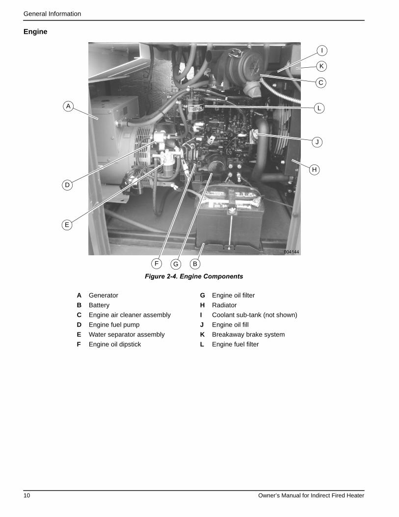
Engine
Figure 2-4. Engine Components
A Generator G Engine oil filter
B Battery H Radiator
C Engine air cleaner assembly I Coolant sub-tank (not shown)
D Engine fuel pump J Engine oil fill
E Water separator assembly K Breakaway brake system
F Engine oil dipstick L Engine fuel filter
004144
A
H
E
D
BGF
K
C
L
J
I
10 Owner’s Manual for Indirect Fired Heater
General Information
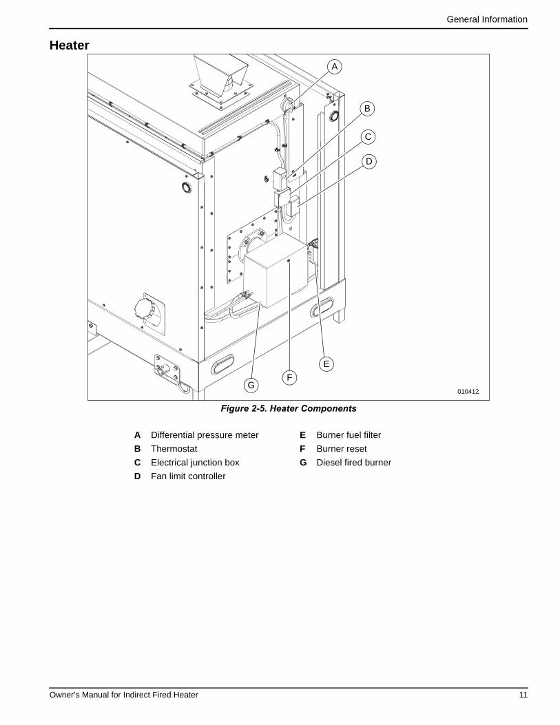
Heater
Figure 2-5. Heater Components
A Differential pressure meter E Burner fuel filter
B Thermostat F Burner reset
C Electrical junction box G Diesel fired burner
D Fan limit controller
GF
E
C
B
D
A
010412
Owner’s Manual for Indirect Fired Heater 11

General Information
Control Panel
Figure 2-6. Control Panel
A Engine control box and ignition E Blower STOP button
B Fuel gauge F Blower ON indicator lamp
C Burner ON-OFF switch G Blower OFF indicator lamp
D Blower START button H Control panel main disconnect switch
008962
3
1
2
A
DC
B F
G
E
H
12 Owner’s Manual for Indirect Fired Heater

General Information
EmissionsThe United States Environmental Protection Agency (USEPA) (and California Air Resources Board (CARB), forengines/equipment certified to California standards)requires this engine/equipment to comply with exhaustand evaporative emissions standards. Locate theemissions compliance decal on the engine to determineapplicable standards. See the included emissionswarranty for emissions warranty information. Follow themaintenance specifications in this manual to ensure theengine complies with applicable emissions standards forthe duration of the product’s life.
Engine Oil RecommendationsChange oil and oil filter at least once every 12 months,even if the hours of operation are fewer than the other-wise recommended service interval. See the applicableengine manual for recommended oil types. Use onlyapproved oil types.
For more information, see the engine manual.
Coolant Recommendation
Use demineralized or distilled water for best results. Hardwater causes scale deposits, which reduces cooling effi-ciency and raises internal temperatures, possibly leadingto engine damage.
See the engine manual for recommended coolants.
Use a Long Life Coolant Antifreeze or Extended LifeCoolant that meets or exceeds these specifications:
• Isuzu Part Number 8-12346-290-0
• ASTM D4985
See the engine manual for recommended coolants.
Test coolant yearly, or every 1,000 hours, whichevercomes first.
For more information, see the engine manual.
Fuel System
The heater is designed to operate with diesel fuel.
IMPORTANT NOTE: Comply with all laws regulatingthe storage, handling, and transporting of fuels.
Follow these guidelines:
• Use only ultra-low-sulfur diesel fuel.
• When temperatures are at or below freezing, useNo. 1D diesel fuel.
• When temperatures are above freezing, use No.2D diesel fuel.
• In some areas of the country, climatized fuel—amixture of 1D and 2D—may also be used.
For more information, see the engine manual.
Trailer Towing Guidelines(000149)
DANGERRisk of poisoning. Do not use mouth to siphon coolant. Doing so will result in death or serious injury.
CAUTION
(000323)
Engine damage. Use approved coolant only. Failure to do so could result in equipment damage.
(000168)
DANGERExplosion and Fire. Fuel and vapors are extremely flammable and explosive. Keep fire and spark away. Failure to do so will result in death or serious injury.
(000204)
DANGERExplosion and Fire. Do not overfill fuel tank. Overfilling may cause fuel to leak and ignite or explode, resulting in death or serious injury.
WARNINGPersonal injury. Trailer must be securely coupled to the hitch with the chains correctly attached. Uncoupled or unchained towing could result in death or seriousinjury. (000233a)
WARNING
Property or Equipment Damage. Tighten wheel lug nuts after first 50 miles to factory specifications. Failure to do so could result in death, serious injury, property or equipment damage. (000235)
WARNINGProperty or equipment damage. Do not alter the trailer. Alterations can damage essential safety items. Doing so could result in death, serious injury, or property or equipment damage. (000285)
Owner’s Manual for Indirect Fired Heater 13

General Information
Driving a vehicle with a trailer in tow is different than driv-ing the same vehicle without a trailer in tow. Consider thefollowing:
• It takes longer to get up to speed.
• More room is needed to turn and pass.
• More distance is needed to stop.
• The driver is responsible for keeping the vehicleand trailer under control.
When towing, make regular stops to verify the following:
• Coupler is secured to the hitch and locked.
• Electrical connections are made.
• Appropriate slack in the safety chains and thebreakaway switch pull-pin cable.
• Tires are inflated to proper air pressure with nodamage or unusual wear to tread or sidewalls.
• Trailer doors are secured and latched.
• Fuel tank is empty.
Other towing guidelines:
• Use the tow vehicles mirrors to verify there isenough room for lane changes or entering/exitingtraffic.
• Allow plenty of stopping distance for the trailer andtow vehicle.
• Do not drive faster than the conditions allow.
• A rule of thumb for passing distance is the distancewith a trailer is four times the passing distancewithout a trailer.
• Use lower gears for climbing and descendinggrades.
• Do not ride the brakes while descending grades;this can cause overheating and potential brake fail-ure.
• Do not apply the tow vehicle brakes to correct ex-treme trailer swaying. Continued pulling of thetrailer, and even slight acceleration, or carefullyapplying the trailer brakes (using the electronicbrake controller) will provide a stabilizing force.
Wheel Chock Guidelines
• Select wheel chock according to equipment typeand size.
• Always use in pairs and on firm surfaces.
• Chock in direction of grade.
• Chock both sides of wheel if direction of grade isunknown.
• Use wheel chock only after parking brake isapplied and tested.
• Center chocks squarely against tread of eachwheel.
• Do not drive over wheel chocks.
Personal injury. Do not operate unit during transport. Doing so could result in death, serious injury, or property damage.
(000231a)
WARNING
(000234a)
WARNINGCrushing hazard. Verify unit is properly secured and on level ground. An unsecured unit can suddenly roll or move, causing death or serious injury.
14 Owner’s Manual for Indirect Fired Heater

Section 3: Operation
Before Starting Engine
Pre-start Checklist
• Remove all flammable materials and fire hazardswithin 5 ft (1.5 m) of unit.
• Keep unit a minimum of 5 ft (1.5 m) from structuresor barricades.
• Keep unit a minimum of 150 ft (45.72 m) away fromopen oil head.
• Verify the unit is not leaking fluids: inspect insideand outside the unit for leaking fuel, engine oil,HTF/hydraulic oil, and engine coolant.
• Verify the following are clear of debris and obstruc-tions:
– Engine air intake
– Engine exhaust stack
– Outlets and fan intakes
• Verify air duct hose is securely fastened to outletduct assembly.
• Check fuel, engine oil, and engine coolant levels.
• Verify unit is properly secure with jacks deployed (ifapplicable), wheels chocked, and level.
• Inspect the alternator drive belt for tension andabnormalities.
• Verify that the burner cover is securely installed.
• Inspect the generator. See the generator manual.
• Verify battery cables are not loose or corroded.
• Inspect ducting for damage or unusual wear.
Engine Oil Level Check
NOTE: If engine was running, wait at least 10 minutesbefore proceeding.
1. Remove oil dipstick from crankcase and wipe itclean with a clean, lint free cloth.
2. Slowly insert the clean oil dipstick into the oil dip-stick tube. Verify the oil dipstick is fully seated.
3. After 10 seconds, remove the oil dipstick and lookat the oil level on both sides. The lower of the tworeadings will be the correct oil level measurement.
4. Add oil (if necessary) to adjust the level. After add-ing or changing the oil, run the engine for one min-ute before checking the oil level. Wait 10 minutesto allow the engine to cool and oil to fully drain intothe oil pan.
Typical causes of inaccurate oil level readings:
• Reading the high level of the oil dipstick.
• Reading the oil dipstick before the oil fully drainsinto the oil pan.
• Inserting and removing the oil dipstick too quickly.
• The oil dipstick is not fully seated in the oil dipsticktube.
Engine Coolant Check
Inspect the coolant sub-tank to check the coolant level.Check the coolant level when the engine is cold, as cool-ant flows to the sub-tank when the radiator is still hot,which provides an inaccurate reading. Replace the cool-ant according to the Maintenance Schedule, or if it iscontaminated or dirty. See Adding Coolant.
Ducting Guidelines
• Place ducting in desired configuration before oper-ating the unit.
(000108)
WARNINGHot Surfaces. When operating machine, do not touch hot surfaces. Keep machine away from combustibles during use. Hot surfaces could result in severe burns or fire.
(000135)
CAUTIONEngine damage. Verify proper type and quantity of engine oil prior to starting engine. Failure to do so could result in engine damage.
(000154)
WARNINGRisk of burns. Do not open coolant systemuntil engine has completely cooled. Doing so could result in serious injury.
Asphyxiation. Running engines produce carbon monoxide, a colorless, odorless, poisonous gas. Carbon monoxide, if not avoided, will result in death or serious injury.
(000103)
DANGER
WARNINGBurn hazard. Do not remove ducting until all air pressure has been emptied from hose duct. Failure to do so could result in severe injury.
(000288)
Owner’s Manual for Indirect Fired Heater 15
Operation
• Tightly secure ducting end to the unit. Verify anyadditional ducting is also tightly secured.
• Avoid sharp bends or 90° turns in the ducting.
• Use only the necessary length of ducting required;do not exceed maximum length.
• Verify that ducting is not in a high traffic area, andwill not impede workers or other machinery. Careshould be taken to prohibit the need to step orclimb over ducting.
• DO NOT place ducting over combustible materials.
• DO NOT place ducting over surfaces that maycause damage or reduce performance, such aswater, sharp rocks or glass, electrical wiring, pip-ing, etc.
• DO NOT place or drape anything over ducting,such as covers, insulation (insulated ducting isavailable), blankets or cloth, or electrical wires.
• Inspect ducting for damage or unusual wear beforeeach use.
Engine and Heater Startup
1. Turn ignition key to RUN and wait for the light toexpire.
2. Turn ignition key to START.
NOTE: Do not hold the engine starter key in the startposition for more than 15 seconds. Doing so will overheatthe starter motor. Wait 30 seconds for the starter motor tocool before making a second attempt to start if the enginefails to start.
3. Warm up engine for 90 seconds.
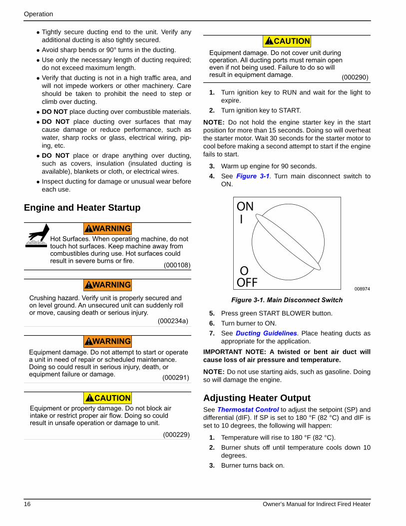
4. See Figure 3-1. Turn main disconnect switch toON.
Figure 3-1. Main Disconnect Switch
5. Press green START BLOWER button.
6. Turn burner to ON.
7. See Ducting Guidelines. Place heating ducts asappropriate for the application.
IMPORTANT NOTE: A twisted or bent air duct willcause loss of air pressure and temperature.
NOTE: Do not use starting aids, such as gasoline. Doingso will damage the engine.
Adjusting Heater OutputSee Thermostat Control to adjust the setpoint (SP) anddifferential (dIF). If SP is set to 180 °F (82 °C) and dIF isset to 10 degrees, the following will happen:
1. Temperature will rise to 180 °F (82 °C).
2. Burner shuts off until temperature cools down 10degrees.
3. Burner turns back on.
(000108)
WARNINGHot Surfaces. When operating machine, do not touch hot surfaces. Keep machine away from combustibles during use. Hot surfaces could result in severe burns or fire.
(000234a)
WARNINGCrushing hazard. Verify unit is properly secured and on level ground. An unsecured unit can suddenly roll or move, causing death or serious injury.
CAUTION
(000291)
Equipment damage. Do not attempt to start or operate a unit in need of repair or scheduled maintenance. Doing so could result in serious injury, death, or equipment failure or damage.
WARNING
CAUTION
(000229)
Equipment or property damage. Do not block air intake or restrict proper air flow. Doing so could result in unsafe operation or damage to unit.
CAUTION
(000290)
Equipment damage. Do not cover unit duringoperation. All ducting ports must remain open even if not being used. Failure to do so will result in equipment damage.
008974
ON
OFF
I
O
16 Owner’s Manual for Indirect Fired Heater
Operation
Engine and Heater Shutdown
1. Turn burner switch to OFF.
2. Allow outlet air temperature to cool for at least 90seconds.
IMPORTANT NOTE: Do not detach ducting until all airpressure has been emptied from hose duct.
3. Press STOP BLOWER button.
4. Turn ignition key to OFF.
Thermostat
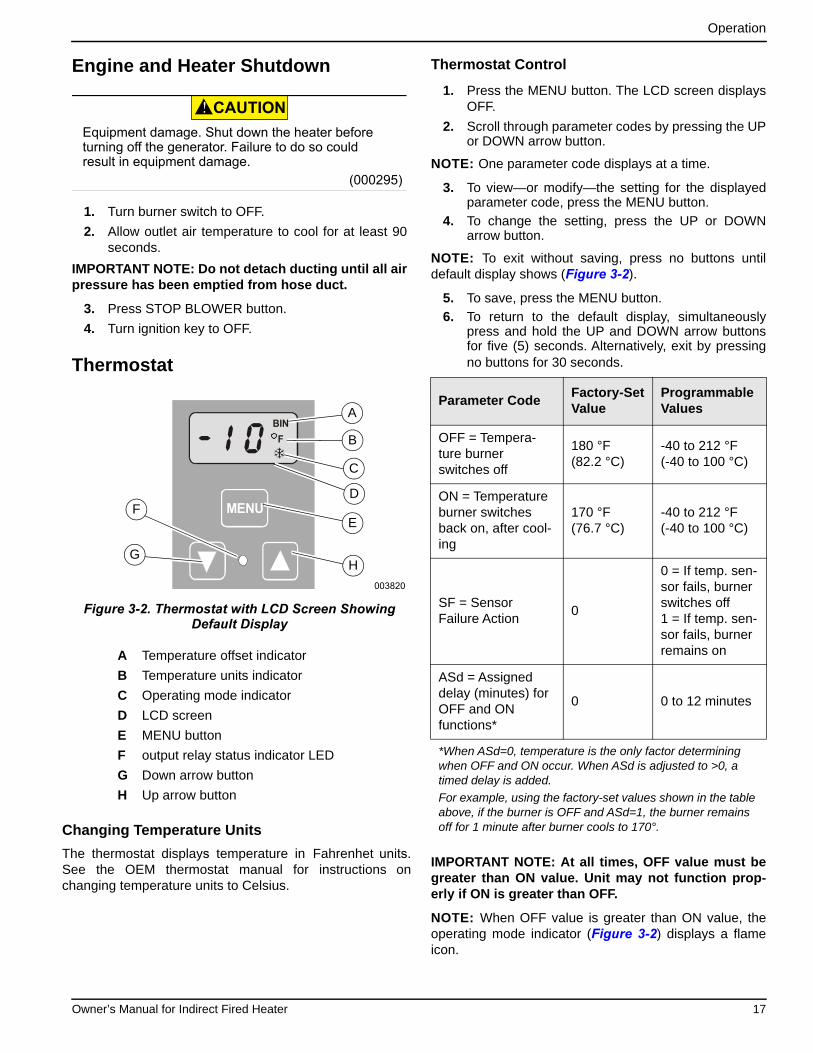
Figure 3-2. Thermostat with LCD Screen Showing Default Display
Changing Temperature Units
The thermostat displays temperature in Fahrenhet units. See the OEM thermostat manual for instructions on changing temperature units to Celsius.
Thermostat Control
1. Press the MENU button. The LCD screen displaysOFF.
2. Scroll through parameter codes by pressing the UPor DOWN arrow button.
NOTE: One parameter code displays at a time.
3. To view—or modify—the setting for the displayedparameter code, press the MENU button.
4. To change the setting, press the UP or DOWNarrow button.
NOTE: To exit without saving, press no buttons untildefault display shows (Figure 3-2).
5. To save, press the MENU button.
6. To return to the default display, simultaneouslypress and hold the UP and DOWN arrow buttonsfor five (5) seconds. Alternatively, exit by pressingno buttons for 30 seconds.
IMPORTANT NOTE: At all times, OFF value must begreater than ON value. Unit may not function prop-erly if ON is greater than OFF.
NOTE: When OFF value is greater than ON value, theoperating mode indicator (Figure 3-2) displays a flameicon.
A Temperature offset indicator
B Temperature units indicator
C Operating mode indicator
D LCD screen
E MENU button
F output relay status indicator LED
G Down arrow button
H Up arrow button
CAUTION
(000295)
Equipment damage. Shut down the heater beforeturning off the generator. Failure to do so could result in equipment damage.
MENU
FBIN
003820
A
D
C
B
H
FE
G
Parameter CodeFactory-Set Value
Programmable Values
OFF = Tempera-ture burner switches off
180 °F (82.2 °C)
-40 to 212 °F(-40 to 100 °C)
ON = Temperature burner switches back on, after cool-ing
170 °F(76.7 °C)
-40 to 212 °F(-40 to 100 °C)
SF = Sensor Failure Action
0
0 = If temp. sen-sor fails, burner switches off1 = If temp. sen-sor fails, burner remains on
ASd = Assigned delay (minutes) for OFF and ON functions*
0 0 to 12 minutes
*When ASd=0, temperature is the only factor determiningwhen OFF and ON occur. When ASd is adjusted to >0, atimed delay is added.
For example, using the factory-set values shown in the tableabove, if the burner is OFF and ASd=1, the burner remainsoff for 1 minute after burner cools to 170°.
Owner’s Manual for Indirect Fired Heater 17

Operation
This page intentionally left blank.
18 Owner’s Manual for Indirect Fired Heater

Section 4: Maintenance
MaintenanceRegular maintenance will improve performance andextend engine/equipment life. Generac Mobile recom-mends that all maintenance work be performed by aGMASD. Regular maintenance, replacement, or repair ofthe emissions control devices and systems may be per-formed by any repair shop or person of the owner’schoosing. To obtain emissions control warranty servicefree of charge, the work must be performed by aGMASD. See the emissions warranty.
Maintenance TasksDaily checks must be performed when unit is operatedcontinuously for extended periods of time. Daily checksand routine monthly checks can be performed by anauthorized operator.
NOTE: Normal maintenance, service, and replacementof parts are the responsibility of the owner and are notconsidered defects in materials or workmanship withinthe terms of the warranty. It is strongly recommendedthat equipment be periodically checked by a GMASD.
Daily Walk Around Inspection
Inspect for conditions that could hinder performance orsafety, such as (but not limited to) oil, coolant, and fuelleakage, blocked vents, loose or missing hardware, andimproper electrical connections. Check for foreign matterblocking vents and on top of unit. Perform any necessarymaintenance tasks. See Trailer Maintenance beforetowing.
• Inspect outer cover for significant damage beyondscuffs and small nicks.
• Inspect for electrical wire abrasion.
• Inspect the fan belt for cracking, fraying, andstretching. Verify the belt is properly seated in thepulley grooves. See Maintenance Schedule.
• Check fluid levels.
• Inspect electrical connectors, battery, and groundpoints. Look for loose or missing hardware.
• Inspect all flexible rubber hoses for deterioration.
• Inspect hydraulic hoses for signs of wear.
• Verify hoses are not crushed, bent, or twisted.
• Verify there are no cracks or corrosion.
• Inspect tires for unusual wear.
• Inspect ducting for damage or unusual wear.
Draining and Refilling the Oil
1. See Figure 4-1. Place container under drain port,or connect hose (A) or piping to drain port leadingto container.
Figure 4-1. Oil Drain Hose Location
2. Remove plug from oil drain.
3. Open drain valve (B). Drain oil.
4. Close drain valve once draining is complete.
5. Remove drain hose or piping, if applicable.
6. See engine manual for oil filter information.
7. See Figure 2-4. Remove filler cap (yellow) (J) onthe rocker arm cover.
8. Fill oil pan to specified level.
9. Replace filler cap.
NOTE: Do not overtighten filler cap. Overtightening maydamage filler cap.
10. Start engine and let run for five minutes. Verifythere are no leaks.
11. Stop engine and let cool for approximately 10 min-utes. Verify oil level is correct. (See Engine OilLevel Check.) Repeat steps 7–9 until oil is prop-erly filled.
(000139)
WARNINGRisk of burns. Allow engine to cool before draining oil or coolant. Failure to do so could result in death or serious injury.
Potential of cancer. Prolonged or repeated contact with used motor oil has been shown to cause cancer in laboratory animals. Thoroughly wash exposed areas with soap and water. (000127a)
WARNING
008969A B
Owner’s Manual for Indirect Fired Heater 19

Maintenance
IMPORTANT NOTE: Do not overfill oil pan. Overfillingmay result in white exhaust smoke, sudden overengine speed, or engine damage.
Adding Coolant
Coolant must be changed every year or at 1,000 hours ofoperation. Check coolant level and degree of foulingaccording to the steps below. Correct coolant level isapproximately 0.39 in (10 mm) below the radiator coretop. Wear proper PPE when handling Long Life Coolant.
1. Verify engine is stopped and cooled.
2. See Figure 4-2. Verify coolant drain plug (A) isclosed.
Figure 4-2. Coolant Drain Plug
3. See Figure 4-3. Remove radiator cap (B).
Figure 4-3. Radiator Location
4. Fill radiator slowly with coolant until it reaches thelip of the filler port.
5. Replace radiator cap.
6. Remove cap (C) from sub-tank.
7. Fill sub-tank with coolant until it reaches the FULLmark.
8. Replace sub-tank cap.
9. Operate engine approximately five minutes at alow idle speed to purge air in the coolant system.
NOTE: Coolant level will drop.
10. Stop engine and, once cooled, replenish with cool-ant until the sub-tank reaches the FULL mark.
(000149)
DANGERRisk of poisoning. Do not use mouth to siphon coolant. Doing so will result in death or serious injury.
WARNINGRisk of burns. Contents under pressure.Do not remove the radiator pressure cap while engine is hot. Doing so could result in death or serious injury. (000322a)
(000154)
WARNINGRisk of burns. Do not open coolant systemuntil engine has completely cooled. Doing so could result in serious injury.
(000165a)
CAUTIONRisk of overheating. Do not use any chromate base rust inhibitor with propylene glycol base antifreeze, boosters, or additives. Doing so will cause overheatingand possible equipment damage.
CAUTION
(000419)
Personal injury. Wear appropriate personal protective equipment at all times while operating and servicing unit. Failure to do so could result in personal injury.
008970
A
008964
B C
20 Owner’s Manual for Indirect Fired Heater

Maintenance
Maintenance SchedulePeriodic inspection, service, and maintenance of this unitis critical to ensuring reliable operation. The following isthe manufacturer’s recommended maintenance sched-ule. The maintenance items need to be performed morefrequently if the unit is used in severe applications (suchas very high or very low ambient conditions or extremelydirty or dusty environments). Use the unit hour meter orcalendar time, whichever occurs first, from the previousmaintenance interval to determine next required mainte-nance interval.
NOTE: Some checks are based on hours of operation.
Follow all applicable safety alerts in this manual or theengine service manual before performing any mainte-nance checks or service.
This maintenance schedule reflects the minimum tasksneeded to verify the unit remains operational. Some ofthe tasks can be performed by an authorized operator,and others must be performed by a GMASD.
NOTE: An authorized operator is one who has beentrained by a GMASD in correct operation and inspectionof this unit.
Engine Maintenance Schedule
Daily
• Check engine oil level.
• Check fuel level.
• Check engine coolant level.
• Drain water from fuel filters.
• Inspect air cleaner, dust unloader valve, and indicator.
• Perform visual walk around inspection.
• Inspect generator windings for dirt or grime.
50 Hour Break-In• Replace engine oil and engine oil filter.
• Inspect and adjust cooling fan V-belt.
Every 500 Hours
• Drain water from fuel tank.
• Drain oil/water separator.
• Service battery.
• Change engine oil and replace oil filter. 1 2
• Inspect coolant pump.
• Inspect open crankcase vent (OCV) system.
• Remove and replace fuel filter elements.
• Inspect belt wear.
• Inspect belt tensioner.
• Inspect cooling system.
• Pressure test cooling system.
• Check and adjust engine speeds.
• Inspect engine mounts.
• Inspect engine ground connection.
Every 1,000 Hours• Inspect generator ball bearings.
• Flush and refill cooling system.
Every 2,000 Hours • Check the DC no load excitation voltage. See generator manual.
Every 3,000 Hours
• Inspect crankshaft vibration damper.
• Adjust valve clearance.
• Test glow plugs for continuity.
Every 6,000 Hours • Test thermostat opening temperature.
Owner’s Manual for Indirect Fired Heater 21

Maintenance
As Required
• Drain water from fuel filters.
• Add coolant.
• Replace air filter element.
• Inspect primary air filter element.
• Replace fan belt.
• Inspect fuses.
• Inspect electrical wiring and connections.
• Purge fuel system.1 During the initial operation of a new or rebuilt engine with Break-In Plus, change the oil and filter between a minimum of 100 hours and amaximum of up to 500 hours.2 Service intervals depend on sulfur content of the diesel fuel, oil pan capacity, and the oil and filter used.
NOTE: For more information, see engine manual.
22 Owner’s Manual for Indirect Fired Heater

Maintenance
Battery Inspection
Always recycle batteries in accordance with local lawsand regulations. Contact your local solid waste collectionsite or recycling facility to obtain information on localrecycling processes. For more information on batteryrecycling, visit the Battery Council International websiteat: http://batterycouncil.org
NOTE: Remove the 5 amp controller fuse from controlpanel.
An authorized operator should inspect the engine batterymonthly. At this time, the battery fluid level should bechecked using a load tester and distilled water added ifneeded. Battery cables and connections should also beinspected for cleanliness and corrosion.
A GMASD should inspect the battery system once everysix months. At this time, the battery condition and state ofcharge should be checked using a load test battery.Recharge or replace the battery as required.
Battery service is to be performed or supervised by per-sonnel knowledgeable of batteries and the required pre-cautions. Keep unauthorized personnel away.
Observe the following precautions when working on bat-teries:
• Remove watches, rings, or other metal objects.
• Use tools with insulated handles.
• Wear rubber gloves and boots.
• Do not lay tools or metal parts on top of battery.
• Disconnect charging source prior to connecting ordisconnecting battery terminals.
NOTE: Wash spilled electrolyte down with an acid neu-tralizing agent. A common practice is to use a solution of1 lb (454 g) bicarbonate of soda (baking soda) to 1 gal(3.8 L) of water. Add the bicarbonate of soda solutionuntil the evidence of reaction (foaming) has ceased.Flush the resulting liquid with water.
NOTE: Discharge static electricity before touching thebattery by first touching a grounded metal surface.
Battery Installation and Replacement
When required, the battery must be replaced with one ofequivalent size, voltage, and CCA (cold crank ampcapacity). Contact a GMASD for correct battery size. Anew battery must be filled with the proper electrolyte andbe fully charged before install.
Battery cables are connected to the unit at the factory.
Proceed as follows to connect cables to battery posts.
1. Connect battery cable from starter contactor topositive (POS or +) battery post.
2. Connect black battery cable to negative (NEG or -)battery post.
3. Refer to Engine and Heater Startup.
(000188)
DANGERElectrocution. Do not wear jewelry while working on this equipment. Doing so will result in death or serious injury.
(000137a)
WARNINGExplosion. Batteries emit explosive gases while charging. Keep fire and spark away. Wear protective gear when working with batteries. Failure to do so could result in death or serious injury.
(000162)
WARNINGExplosion. Do not dispose of batteries in a fire. Batteries are explosive. Electrolyte solution can cause burns and blindness. If electrolyte contacts skin or eyes, flush with water and seek immediate medical attention.
(000163a)
WARNINGRisk of burn. Do not open or mutilate batteries. Batteries contain electrolyte solution which can cause burns and blindness. If electrolyte contacts skin or eyes, flush with water and seek immediate medical attention.
(000130)
WARNINGAccidental Start-up. Disconnect the negative battery cable, then the positive battery cable when working on unit. Failure to do so could result in death or serious injury.
WARNING
(000228)
Environmental Hazard. Always recycle batteries at an official recycling center in accordance with all local laws and regulations. Failure to do so could result in environmental damage, death, or serious injury.
WARNINGExplosion hazard. Never add acid to a battery.Add distilled water only. Failure to do so could result in death, serious injury, or equipment damage. (000316)
(000167a)
CAUTIONEquipment damage. Do not make battery connections in reverse. Doing so will result in equipment damage.
Owner’s Manual for Indirect Fired Heater 23

Maintenance
Other Maintenance ChecksThe following inspections should be performed by anauthorized service technician, or a properly trained auth-orized operator. These maintenance items require a highlevel of experience and skill to evaluate and correct.
• Inspect engine accessory drive belts.
• Inspect hoses and connections.
• Inspect fuel supply system.
• Inspect exhaust system.
• Inspect exhaust pipe sleeve.
Trailer MaintenancePerform daily inspections of the trailer before each use.
• Inspect trailer for damage, such as dents, cracks,gouges, or deep scratches.
• Inspect trailer for corrosion or abrasion.
• Inspect trailer tires for wear and deflation.
• Inspect all safety devices for damage or unusualwear.
• Inspect all electrical connections for any bare wiresor other damage.
• Rectify any issues before using the trailer.
Short Term StorageWhen the machine will not be in use for three or moremonths, follow the guidelines below to properly store themachine:
• Perform all necessary maintenance or repairsbased on the Maintenance Schedule. Performany upcoming necessary maintenance task beforestoring.
• Fill the fuel tank to FULL.
• Fill coolant to FULL. Do not drain.
• Remove all dirt and debris from inside and outsidethe enclosure.
• Lock the machine to prevent any unauthorizedoperation.
• Store in a safe location — do not position near oron top of any combustible materials; observe anylocal, state, or national codes or regulations. Storein a low moisture, low dust area.
• Disconnect the negative cable from the battery.
• Grease exposed components and joints of theengine accelerator system.
Return to ServiceFollow the guidelines below for engines and machinesthat have not been operated for three to six months:
• Conduct a thorough inspection of the machinebefore starting the engine.
• Verify the maintenance schedule is up to date.
• Connect the negative battery cable.
• After starting the engine, let it warm up for morethan 10 minutes at idle.
24 Owner’s Manual for Indirect Fired Heater

Section 5: Troubleshooting
General Troubleshooting GuideProblem Cause Solution
Engine will not crank
Low battery output voltage or discharged battery.
Charge or replace batteries. See Bat-tery Inspection.
Loose or corroded connections. Clean and tighten connections.
Faulty start circuit relay. Contact a GMASD.
Blown fuse. Replace fuse.
Faulty main switch or start safety switch. Repair switch as required.
Faulty starter solenoid. Replace solenoid.
Faulty starter. Replace starter.
Starter cranks slowly
Low battery output voltage or discharged battery.
Charge or replace batteries. See Bat-tery Inspection.
Excessive crankcase oil viscosity.Drain crankcase oil and replace with correct viscosity oil. See Draining and Refilling the Oil.
Loose or corroded connections. Clean and tighten connections.
Hard to start or will not start
Engine starting under load. Disengage PTO.
Incorrect starting procedure.Review starting procedure. See Pre-start Checklist and Engine and Heater Startup.
Restricted exhaust. Inspect and correct exhaust restriction.
No fuel. Check fuel tank.
Air in fuel line. Purge fuel lines. See engine manual.
Poor fuel quality.Drain fuel and replace with proper grade and quality of fuel for operating condition.
Water, dirt, or air in fuel system. Drain, flush, fill, and purge fuel system.
Fuel filter restricted or full of water. Replace fuel filter or drain water from fuel filter.
Dirty or faulty fuel injectors.Contact a GMASD.
Electronic fuel system failure.
Cold weather. Use cold weather starting aids (see engine manual).
Excessive crankcase oil viscosity.Drain crankcase oil and replace with correct viscosity oil. See Draining and Refilling the Oil.
Electronic control system problem or basic engine problem. Contact a GMASD.
Owner’s Manual for Indirect Fired Heater 25

Troubleshooting
Problem Cause Solution
Engine misfiring or runs irregularly
Poor fuel quality; incorrect fuel/dirty fuel. Test fuel, drain water from fuel bowl.
Restricted fuel filter. Replace fuel filter element.
Water, dirt, or air in fuel system. Drain, flush, fill, and purge fuel system.
Low coolant temperature. Remove and check thermostat.
Dirty or faulty fuel injectors.
Contact a GMASD.Electronic fuel system problem.
Electronic control system problem or basic engine problem.
Lack of engine power
Restricted air intake. Service air cleaner.
Restricted exhaust. Check and correct exhaust restriction.
Poor fuel quality.Drain fuel and replace with proper grade and quality of fuel for operating condition.
Restricted fuel filter. Replace fuel filter elements.
Engine overloaded. Reduce engine load.
Incorrect crankcase oil.Drain crankcase oil and replace with correct viscosity oil. See Draining and Refilling the Oil.
Low coolant temperature. Remove and check thermostat.
Incorrect valve clearance. Adjust valve clearance or contact a GMASD.
Dirty or faulty fuel injectors. Contact a GMASD.
Air leak in engine intake or exhaust mani-fold.
Check intake and exhaust manifold gaskets and manifolds; repair as required or contact a GMASD.
Engine is in derate due to DTC.Contact a GMASD.Electronic control system problem or basic
engine problem.
Engine idles poorlyPoor fuel quality.
Drain fuel and replace with proper grade and quality of fuel for operating condition.
Electronic control system problem or basic engine problem. Contact a GMASD.
Excessive fuel consumption
Engine overloaded. Reduce engine load.
Restricted or dirty air cleaner. Replace air cleaner element as required.
Insufficient compression. Determine cause of low compression and repair as required.
Leaks in fuel supply system. Locate source of leak and repair as required.
Poor fuel quality/improper type of fuel.Drain fuel and replace with proper grade and quality of fuel for operating condition.
Incorrect valve clearance. Adjust valve clearance or contact a GMASD.
Dirty or faulty fuel injectors.
Contact a GMASD.Electronic fuel system failure.
Electronic control system problem or basic engine problem.
Low engine temperature. Remove and check thermostat(s).
26 Owner’s Manual for Indirect Fired Heater

Troubleshooting
Problem Cause Solution
Fuel in oil
Restricted fuel return line. Check and fix fuel return lines.
Engine load too light. Increase engine load.
Leaking fuel injectors. Contact a GMASD.
Low-pressure fuel system — fuel pressure low
Restricted fuel filter. Replace fuel filter.
Restricted fuel line. Locate restriction, repair as required.
Faulty transfer pump. Contact a GMASD.
Faulty high-pressure fuel pump. Remove fuel pump, repair/replace pump as required.
Abnormal engine noise
Worn main or connecting rod bearings.
Contact a GMASD.
Excessive crankshaft end play.
Loose main bearing caps.
Worn connecting rod bushings and piston pins.
Scored pistons.
Worn timing gears or excess backlash.
Excessive valve clearance.
Worn camshaft lobes.
Worn rocker arm shaft(s).
Worn valve guides.
Damaged valve retainers.
Loose or worn rocker arms.
Bent pushrods.
Broken valve springs.
Bent connecting rods.
Worn flywheel.
Loose flywheel.
Excessive piston to liner clearance.
Excessive thrust bearing clearance.
High oil viscosity.
Engine emits white smoke
Insufficient engine compression.Determine cause of low compression and repair as required, or contact a GMASD.
Faulty thermostat(s) (does not close). Test thermostats; replace thermostats as required.
Coolant entering combustion chamber (failed cylinder head gasket or cracked cyl-inder head).
Repair or replace as required, or con-tact a GMASD.
Electronic control system problem or basic engine problem. Contact a GMASD.
Poor fuel quality or incorrect type of fuel.Drain fuel and replace with proper grade and quality of fuel for operating condition.
Low engine temperature. Warm up engine to normal operating temperature.
Faulty fuel injectors. Contact a GMASD.
Owner’s Manual for Indirect Fired Heater 27

Troubleshooting
Problem Cause Solution
Engine emits black, gray, or blue smoke
Restricted or dirty air cleaner. Replace air cleaner element as required.
Incorrect type of fuel.Drain fuel and replace with proper grade, type, and quality of fuel for oper-ating condition.
Engine burning oil.
Contact a GMASD.Electronic control system problem or basic engine problem.
Cracked or damaged exhaust filter.
Dirty fuel injectors.
Engine overheats
Restricted or dirty air cleaner. Replace air cleaner element as required.
Insufficient coolant in cooling system.
Fill cooling system to proper level. Check radiator and hoses for loose connections or leaks. See Adding Coolant.
Insufficient engine oil. Check oil level. Add oil as required. See Draining and Refilling the Oil.
Dirty radiator core. Clean cooling system as required.
Cooling system needs flushing. Flush coolant system.
Engine overloaded. Reduce engine load.
Loose or faulty fan belt. Check automatic belt tensioner and belts. Replace as required.
Faulty or wrong type of thermostat(s). Test thermostat opening temperature, replace thermostats as required.
Faulty radiator cap. Replace radiator cap as required.
Faulty temperature gauge or sender. Check coolant temperature with ther-mometer and replace if necessary.
Incorrect grade of fuel.Drain fuel and replace with proper grade, and quality of fuel for operating condition.
Damaged or leaking cylinder head gasket.Contact a GMASD.
Faulty coolant pump.
Coolant temperature below normal
Faulty thermostat(s). Test and replace thermostats as required.
Faulty temperature gauge or temperature sender.
Check gauge, sender, and connec-tions.
Coolant in crankcase
Faulty cylinder head gasket.
Contact a GMASD.
Cracked cylinder head or block.
Leaking cylinder liner seals.
Pitted cylinder liners.
Leaking oil cooler.
Faulty oil cooler O-rings.
Leaking EGR cooler system.
Faulty coolant pump seal; weep hole plugged; coolant leaking through bearing.
28 Owner’s Manual for Indirect Fired Heater

Troubleshooting
Problem Cause Solution
Excessive oil consumption
Insufficient crankcase oil viscosity.Drain crankcase and refill with correct viscosity oil. See Draining and Refill-ing the Oil.
Excessive crankcase oil. Drain oil until oil level is correct. See Draining and Refilling the Oil.
External oil leak(s). Determine source of oil leak(s) and repair as required.
Restricted crankcase vent tube. Clean vent tube, verify that crankcase oil level is correct.
Excessive oil pressure.
Contact a GMASD.
Worn, broken, or unseated oil control rings.
Scored cylinder liners or pistons.
Worn valve guides or stems.
Faulty turbocharger.
Front and/or rear crankshaft oil seal faulty.
Piston ring gaps not staggered.
Insufficient piston ring tension.
Piston rings sticking in ring grooves.
Piston ring grooves excessively worn.
Batteries will not charge
Loose or corroded connections. Clean and tighten connections.
Sulfated or worn-out batteries. Replace batteries. See Battery Instal-lation and Replacement.
Stretched belt or faulty belt tensioner. Adjust belt tension or replace belts.
Entire electrical system does not function
Faulty battery connection. Clean and tighten connections.
Sulfated or worn-out batteries. Replace batteries. See Battery Instal-lation and Replacement.
Blown fuse. Replace fuse.
Generator overheating
Overloaded generator. Reduce load.
Clogged ventilation screens. Remove debris and clean air pas-sages.
High altitude. Reduce load or improve ventilation. Contact a GMASD.
Insufficient air circulation.
Contact a GMASD.
Unbalanced load.
Abnormal generator noises
Faulty bearing.
Loose or misaligned coupling.
Belt slap or loose guards.
Thermostat not functioning
Incorrect wiring.
Contact a GMASD.Insufficient supply voltage.
Incorrect sensor operation.
Display shows fault code. See thermostat manual, or contact a GMASD.
No heat Burner malfunction. Contact a GMASD.
Owner’s Manual for Indirect Fired Heater 29

Troubleshooting
This page intentionally left blank.
30 Owner’s Manual for Indirect Fired Heater

Section 6: Wiring Diagrams
Cabin Harness Wiring
3
FM
4321
CR
WIRE COLOR
JB
BL TS DPS
LC
GEN
GROUP G
WIRNG - DIAGRAM
WD SD-MIH800 CABIN
DRAWING #: A0000261121
REVISION: -A-
DATE: 7/11/19 PAGE 1 OF 6
Owner’s Manual for Indirect Fired Heater 31

Wiring Diagrams
Control Box Components
MLCB
COMPONENTS LOCATED IN CONTROL BOX
PDB
PTB
M1
CB1 CB2
SS1
PB1
PB2
LT1
LT2
GNDB
GNDR
GROUP G
WIRNG - DIAGRAM
WD SD-MIH800 CABIN
DRAWING #: A0000261121
REVISION: -A-
DATE: 7/11/19 PAGE 2 OF 6
32 Owner’s Manual for Indirect Fired Heater

Wiring Diagrams
Cabin Harness Schematic
GROUP G
SCHEMATIC - DIAGRAM
WD SD-MIH800 CABIN
DRAWING #: A0000261121
REVISION: -A-
DATE: 7/11/19
MLCB
PDB
GNDL GNDB
M1 M1
FM
CB1PTB
CRPTB
CB2
PTB
PTB PTB PTB PTB
PTB PTB
SS1
M1
PTB
PB1 PB2
M1M1
M1
M1
LT1
LT2
PAGE 3 OF 6
Owner’s Manual for Indirect Fired Heater 33

Wiring Diagrams
Trailer Wiring
WIR
E C
OLO
R L
EG
EN
D
LEG
EN
D
3020688_B_10.16.19
34 Owner’s Manual for Indirect Fired Heater


Part No. A0000244048 Rev. A 11/25/2019
©2019 Generac Mobile Products, LLCAll rights reserved.Specifications are subject to change without notice.No reproduction allowed in any form without prior written consent from Generac Mobile Products, LLC.
Generac Mobile Products, LLC215 Power Drive, Berlin, WI 54923
GeneracMobileProducts.com │800-926-9768 │920-361-4442