mii/prf-53 134 26 january 1996 performance specification
TRANSCRIPT
INCH-POUND 1MII/PRF-53 13426 January 1996
PERFORMANCE SPECIFICATION
ULTRALIGHTWEIGHT CAMOUFLAGE NET SYSTEM (ULCANS)
This spec~lcation is approved for use by aUDepartments and Agencies of the Department ofDefense.
1. SCOPE
1.1 w. This specification covem the ukralightweight camouflage net systems (ULCANS)for tactical equipment and field installations including helicopters and freed wing aircraft.
1.2 Classification. Tire ULCANS covered by this specification sbaU be of the following typesaa specified:
Type 1 - Aviation, OH-58D Helicopter System, Radar Scattering
Type 11- Aviation, AH-64/UH-60 Helicopter System, Radar Scattering
Type III - General Purpose, Modular, Radar Transparent
Type IV - General Purpose, Modular, Radar Scattering
Class 1 - Woodland
Beneficial comments (recommendations, additiorrs, deletions) and rmypertittent data which may beof usc in improving this document should be addressed to: USA COMMCTNS-ELE~ CMD,LOG RSCH CTR, AITN AMSEL LC ED BD, 10115 GRIDLEY RD. STE 228, ~ BELVOIR VA22060-5849 by using the Standardization Document Improvement Proposrd (DD Form 1426)apPe~g at the end of this document or by letter.
AMSC NIA FSC 1080DISTRIBUTION STATEMENT A. Approved for public use, distribution is unlimita.t.
Downloaded from http://www.everyspec.com

MIL-PRF-53134
2. APPLICABLE DOCUMENTS
2.1 General. The documents listed in this section are needed to meet the requirementsspecified in sections 3, 4, and 5 of this speciilcation. This section does not include documentscited in other sections of this specification or recommended for additional information or asexamples. While every effort has been made to ensure the completeness of this list, documentusers are cautioned that they must meet afl specitled requirements documents cited in sections 3,4, and 5 of this specification, whether or not they are listed.
2.2 Government documents.
2.2.1 Mrecifications and standards. The following speciflcatiorrs and standards form a part ofthis document to the extent specified or referenced to herein. Unfess otherwise specified, theissues of these documents are those listed in the issue of the Department of Defense Index ofSpecifications and Standards (DoDISS) and supplement thereto, cited in the solicitation (see 6.2).
SPECIFICATIONS
DEPARTMENT OF DEFENSE
MILW-4088 -MILC-52765 -MILC-53004 -
STANDARDS
FEDERAL
FED-STD-191 -
Webbing, Textile, Woven Nylon.Camouflage Screening Support Systems.Camouflage Screening Systems Lightweight, Synthetic, Woodland,Desert and Snow.
Textife Test Methods.
DEPARTMENT OF DEFENSE
MLSTD- 130 - Identilcation Marking of U.S. Mfitary Property.MIL-STD-81O - Envimtrrnentrd Test Methods and Engineering Guidefines.MIIAWD-882 - System Safety Pmgranr Requirements.MILSTD-1472 - Human Engineering Design Criteria For Military Systems, Equipment
and Facilities.
(Unless otherwise indicated, copies of the above specflcations and standards are avaifable fmmtfre: STDZN DCMNT ORDER DESK, BLDG 4D, 700 ROBBINS AVE. PHILADELPHL4 PA19111-5094.)
Downloaded from http://www.everyspec.com
MIL-PRF-53 134
2,2.2 Orher Government drawirws. The following other Government drawings form a parr ofthis document to the extent specified herein. Unless otherwise specified. the issues are those ineffect on the date of the solicitation.
DRAWINGS - ME
13226E0964 -13227E0131 -13227E0132 -13227E0134 -13227EO136 -
Case, Camouflage screen, Woodland/Desert.Cloth, VirtyI-NylCm.Pole, Aluminum, Support.Pole, Plastic, SupportStake, Anchor, Class 1.
I 13227E0137 - Case, Carrying, Camouflage Screening Support Systems.
(Copies of drawings required by conwactors in connection with specflc acquisition functinnsshould be obtained from the: US Army CECOM Research, Development and EngineeringCenter, Night Vision and Electronic Sensors Directorate, A’ITN AMSEL-RD-NV-CD-CCD,10221 Burbeck Road, Suite 430, Fort Belvoir VA 22060-5806.)
2.3 Non-Government mrblications. The following non-Govemrnent publications form a partof this document to the extent specified herein. Unless otherwise specified, rhe issues nf thedocuments which are DoD adopted are those listed in the issue of the DoDISS cited in thesolicitation. Unless otherwise specifted, the issues of documents not listed in the DoDISS are theissues of ffredocuments cited in the solicitation (see 6.2).
AMERICAN SOCIETY FOR TESTING AND MATERIALS (ASTM)
B117 -D 751 -D 2244 -
D 2247 -
D 2261 -
D 3659 -D 3787 -
D 5034 -E 308 -G26 -
Standard Test Method of Salt Spray (Fog) Testing.Standard Test Methods for Coated FabricsStandard Test Method of Color Differences from Instrumentally Measured ColorCoordinates El.Standard Test Methnd for Testing Water Resistance of Coatings in 1007. RelativeHumidity.Standard Test Method fnr tearing Strength of Woven Fabrics by tbe Torque(Single Rip) Method (Corrstars:-Rate-of-ExterssionTerrsife Test Method).Flammability of Apparel Fabrics by Semi-Restraint Method.Standard Test Method for Bursting Strength of KnittedGonds-Cottstant-Rate-of-Traverae (CRT) Ball Burst Test.Standard Test Method for Breaking Force and Elongation of Textife Fabrics.Standard Method for Computing the Colors of Objects Using the CIE System.Standard Practice for Operating Light Exposure Apparatus (Xenon-Arc type) withand without Water for Exposure of Nonmetallic Materials.
(Copies of ASTM standards can be obtained from: AMERICAN SOCETY FOR TEST ANDMATERIALS, 1916 RACE STREET, PHILADELPHIA PA 19103.)
Downloaded from http://www.everyspec.com

MIL-PRF-53134
CIE51 - A Method for Assessing the Quality of Daylight Simulators for Calorimetry
(Copies of CtE documents can be obtained from TLA Lighting Consultants, Seven Pond Street,Salem MA 01970.)
AMERICAN ASSOCIATION OF TEXTILE CHEMISTS AND COLORISTS (AATCC)
301988- Anti-Fungal Activity, Assessment nn Textile Materials, Mildew and Rot Resistanceof Textile Materials.
(Copies nf these documents can be obtained from the American Association of TextifeChemists and Colnrists, 1 Davis Drive, PO Box 12215, Research Triangle Park, Rafeigh NC27709.)
NATIONAL AERONAUTICAL STANDARD
NAS 1756 - Streamer, Warning.
(Copies of thii document can be obtained from the Aerospace ktdustnes Association ofAmerica, Inc., 1250 Eye Street NW, Washington DC 20005.)
2.3 Order of mwederrce. In the event of a cnnilict between document and references citedherein, the text of this document takes precedence. Notimg in this document, however,supersedes applicable laws and regulations unless a specific exemption bas been obtained.
3. REQUIREMENTS
3.1 Svstem description. UItralightweight camouflage net system (hereafter designated“LJLCANS”) is to provide concealment of mithary aircraft and ground equipment when tacticallydeplnyed (see 6.3.5). ULCANS shall provide visual, electm-optic, radar, and infrared signaturereduction characteristics. ULCANS shall be made of easily and rapidly deployable andrecoverable (see 6.3.6), srtag-resistan~ tdtmlightweight materiaL ULCANS types I and II shalf beused for aviation and ULCANS types III and IV shall be used for general purpose. ULCANSshall not be the source of Fo~ign Object Damage (POD). W-CANS shall be field repairable andmaintainable, fm retardant, shall not show performance degradation when exposed to Petroleum,Odor Lubricants (POL) or when properly stored for extended periods, and shalt be mildew androt resistant. ULCANS shall be used in all weather condkiorts by soldiers dressed in full MissionOriented Protective Posture (MOPP) gear and cold weadter clothing.
3.1.1 Svstem size..
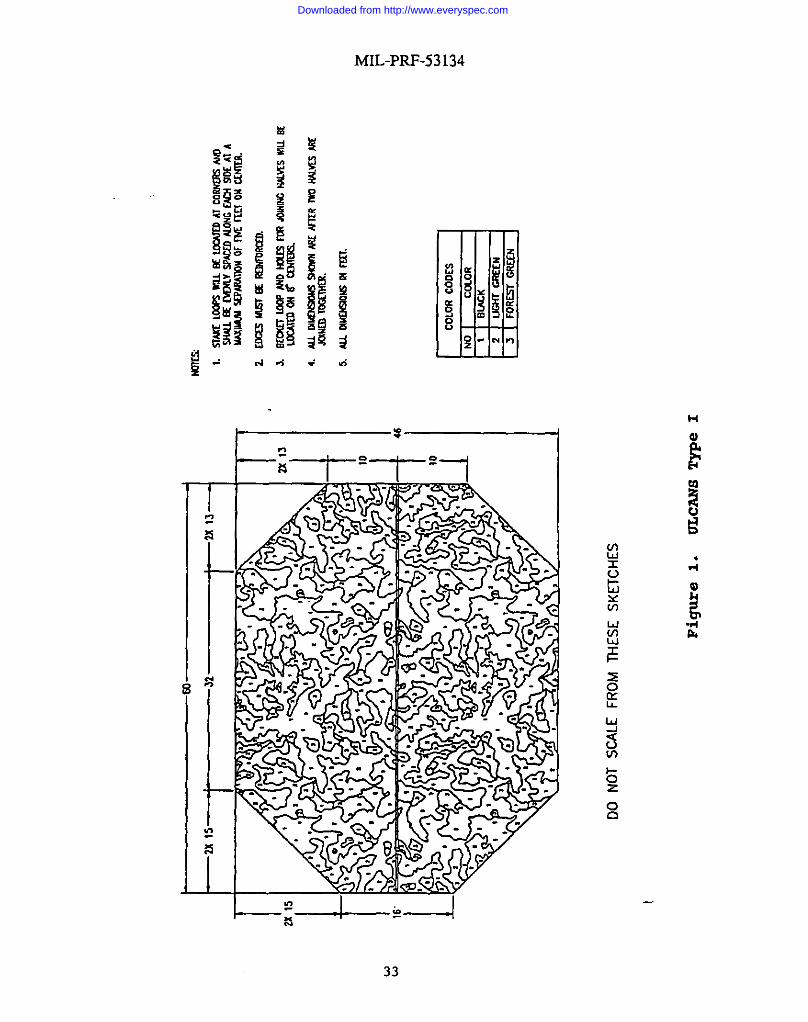
3.1.1.1 ~. Type I ULCANS shall be capable of concealing an OH-58D helicopter inaccordance with figure 1.
Downloaded from http://www.everyspec.com

MIL-PRF-53134
3.1.1.2 -. Type 11ULCANS shall be capable of concealing an AH-64 helicopter or aUH-60 helicopter io accordance with figure 2.
3.1.1.3 Tvr)es III and IV. Types IfI and IV ULCANS shall be in accordance with figure 3.
3.1.2 Svstemwei~ht.
3.1.2.1 Screen weis!ht. ~efinished screen, witibecket loops, reinfoud edging mdstieloops shall not exceed an average weight of 6 ounces per square yard.
3.1.2.2 Totrdsvstemwei~ht. Total system weight inchrdesboth scrmnmd support systemwith storage and transport containers and shafl not exceed the weights listed in table I.
TABLE I. Total svstem wei~h~
Screen Type Total System Weight
1 180 Lbs.
n 350 Lbs.
III&IV 120 Lbs.
3.1.3 SWem vohrme. Aviation type screen system volume inchrdes both screen and supportsystems when field packed in accordance with the operator’s mamraf.
3.1.3.1 ~. Type I ULCANS volume, when field packed, shall not exceed 25 cubic feet.
3.1.3.2 =. Type II W.-CANS vohrme, when field packed, shall not exceed 40 cubic feet.
3.1.4 Sw.tem comrronents. ULCANS shall consist of the following components:
3.1.4.1 Screen swstem. Screen system shall consist of camouflage screens, repair kit, operatorand maintenance manual, and storagcftransport container. In addition, types I and U shall haverotor blade tip covers, wire cutter covers and snag cover for main rotor hubs.
3.1.4.2 Surmort svstem. Support system shrdl consist of ground stakes, screen supports, shapedisrupters, and storagehranspott container in tbe quantities listed in table If.
Downloaded from http://www.everyspec.com

MIL-PRF-53134
TABLE D. Number of surxrort svstem comoonenLs.
Support system Stakes Screen Supports Shape StoragcYTYarrsportDisrupters Container
Type I 40 6 6 1Type II 56 10 10 1Types III &IV 24 12 6 1
3.1.4.2.1 Hei!zbt of suDuort poles. Table IIf lists the beigbt of support poles.
TABLE III. Height of suPDortpoles.
ULCANS SUppOrt Height of poles Height of poles retractedsystem
Type 1 192” (max. extension) 62”
Type II 192” (max. extension) 62”
Types ID& IV 48” NIA
3.2 Svstem performance rerruirements.
3.2.1 Total svstem rermi~ments.
3.2.1.1 Erection times. ULCANS shall be designed so that the screens can be erected in thetimes specitled under the following conditions.
3.2.1.1.1 ULCANS tvpe I and If. ULCANS types I and fl shaft be designed so that threeexperienced soldiers (see 6.3. 10) can deploy the system in Iess than 40 minutes in standardconditions, as defined in 3.2.1.4.1.
3.2.1.1.2 ULCANStvD es ID and IV. When tested as specified in 4.4.2.1.1.2, ULCANS typesIfI and IV sbaff be designed so that three experienced soldiers can deploy the system in a timeequat to or less than it rakes to deploy an equivalent number of the Army’s current L@rtweightCamouflage Screen System (LCSS) screens.
3.2.1.2 Removal times. ULCANS shall be designed so that the screens can be removed(recover) (see 6.3.6) in the times specified under the foflowing conditions.
3.2.1.2.1 ULCANS tvDes I and D. ULCANS types I and II shrdt be capable of going from astate of full deployment to being broken down by three experienced soldiers in such a mannerthat the aircraft can fly away, leaving all ULCANS components behkrd, within 5 to 10_minutesunder standard conditions; and no longer than 10minutes while at MOPP level N.
6
Downloaded from http://www.everyspec.com
M1L-PRF-53134
3.2.1 .2.2 ULCANS twes Ill and fv. When tested as specified in 4.4.2.1.2.2, ULCANS type111and IV shall be designed so that three experienced soldiers can remove the system in a timeequal to or less than it tafcesto remove an equivalent number of LCSS screens.
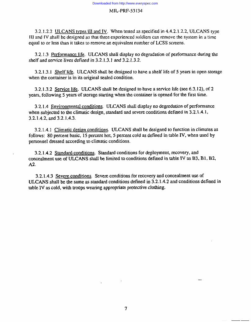
3.2.1.3 Performance life. ULCANS shalf display no degradation of performance during thesheff and service lives defined in 3.2.1.3.1 and 3.2.1.3.2.
3.2.1.3.1 Shelf life. ULCANS shall be designed to have a shelf life of 5 years in open storagewhen the container is in its original seafed condition.
3.2.1.3.2 Service life. ULCANS shall be designed to have a service life (see 6.3.12), of 2years, following 5 years of storage starting when the container is opened for the fust time.
3.2.1.4 Environmental conditions. ULCANS shafl display no degradation of performancewhen subjected to the climatic design, standard and severe conditions defined in 3.2.1.4.1,3.2.1.4.2, and 3.2.1.4.3.
3.2.1.4.1 Climatic desien conditions. ULCANS shrdl be designed to function in climates asfoflows: 80 percent basic, 15 percent hot, 5 percent cold as defined in table IV, when used bypersonnel dressed according to climatic condkions.
3.2.1.4.2 Standard conditions. Standard conditions for deployment, recovery, andconcealment USEof ULCANS shall be timited to condkions defined in table IV as B3, B1, B2,A2.
I3.2.1.4.3 Severe conditions. Severe conditions for recovery and conceahnent use of
I ULCANS shall be the same as standard conditions defined in 3.2.1.4.2 and conditions defined inI table N as cold, with troops wearing appropriate protective clothiog.
I
Downloaded from http://www.everyspec.com

LmmvcDedgn
m
Ha
IHo
tI
l-==
F- *
sash
sack
“i-=- Lse
wnw
Cpmtb.lcmfbra
SLOWad
Tm61Cw
d.!bm
ww,
(OST
AG2s0’)
AIrbhntxn
add!SadkMonSph
An!bbMR8
W8
GmLM
SulamTanF
~w,ti
IkriuxdAk
Tmpm
m(w’/m
q’Hm
My
ln%t@
Main
Hunfdif
‘F?C
)w
Tewe
rahm
Trc]
.%vrc}
%
W-m
Wmmm
atom
3!98
T4S
1s91bm
1107
(ato49)
(Oe.lln)
(03)
(’33!071)
HwHu
nHearnM
So(0S43
691C
.SS
la8!017
911Q
1W14!080
mpltow
(Omlme)
(Sk)
(33t071)
COmmH!#l
Nm)/c+m
iwi7S
NqiQbb
m!olm
NA
NA
Nwtjtiraa
mulCQ
HwnM
!y(FI)
(24)
mQTI
Vaf?abbW
nmos
Olom
74tom
tznw)
7EM
U145
18!07$
Hm~
(S2)
(23103s)
(0Inm)
(2$!023)
SadcHG
40820110
Otoz$s
14bM
140(W)
10IO!8
M6b14S
6!044
w(W
I0431
ploftal
(3!023)
Sadctiu
.sm+s
No$@
!bTens’qwa
rd.s
I+T
‘!8.13to.20
(cl)
(.2120.=)
Tnrd~wad
Wmlbn
ratumil
(2s1
0.33]
~(ml
-25tom
N@2ib
Tmmjwa
d(w
to48)
+aWI
<1e
a10a
Terdtitmardcaimlbn
Cmlmtb”
t.3T!,.k8]
Ww!
aN9w2JbW
Tm-
.an{.s0
<!8
1,*!nwti sam
lb”
(u]
(wmaw
sabm
bn(:)
{41)
*Designationsin
psrentbese$refextn
mrrs-spnnding
climatic
categnriex
inquadzipmite
Standardization
Agre8m
ent360Cfirnmic
Environmenfa/
ComfifimsAj&c2ingtheDesignoflfilikuyM
rJfctiel.Twon
ftheQST
At3
360categories,
COandC4
,arenntused
bytheUoitedStates
NOTEThe num
bers
shnw
nfortheclimatic
elem
ents
representonly
tbeUP
IX?Jandlnwe
rlimits
nfdtecyclesthat
typify
days
during
wbicb
theextreme$
ncmrr,
e.g.,fortieHot-Drycycle,120“Fistbemaxhrmmdaytimetempcrstoreand90‘Fistheminimumnighttime(mearlymnmiogtemperature).
Materielshallbedesignedto
functinn
atanyandallp
ointsin
tieapplicable
range.
TABLE
fV,
Cliiatic
de$ien
conditions,
I
‘W=watt,
nra=meter
squared
Downloaded from http://www.everyspec.com

MfL-PRF-531 34
3.2.1.4.4 Sand, dust. freezing rain and ice. When tested in accordance with 4.4.2 .1.3.2 and4.4.2.1.3.3, ULCANS support systems shall be designed to withstand exposure to sand and dustparticles up to 1000 micrometers in size, and ice and freezing rain glaze of 0.9 specific gravity atl/2-inch thickness with no system component failures.
3.2.1.4.5 w. When tested in accordance with 4.4.2.1.3.1, ULCANS shall remain erect inwind conditions up to 46 miles per hour (mph). ULCANS types I and II shall also remaindeployed when subjected to 46 mph winds from a hovering helicopter.
3.2.2 Screen sw.tem retruirements. ULCANS screen system, consisting of camouflage screens,repair kit, operators and maintenance manual, storagehransport container and, for types I and U,rotor blade tip covers, wire cutter covers, and snag cover for main rotor hubs shall conform to thefolfowing requirements
3.2.2.1 Foreim obiect damace. Screens sbafl be designed to eliminate FOD and snagging, andshall not contain any materials that could become a source of damage. Screens shrdl beconstructed to prevent stones, twigs, leaves and other debris from becoming enmeshed in thescreens when they are on the ground and then falling onto equipment when the screen isdeployed. Screens shrdl rdso not produce any residue or discharge inchrding carbon dust or fibersthat could present the potential for damage to any elecrncal systems or components.
3.2.2.2 Color and .wrectrslreflectivity. when tested as specKled in 4.4.2.2, before and afterPOL exposure, the color and spectral reflectivity shall be as specified in 3.2.2.2.1 and 3.2.2.2.2.
3.2.2.2.1 ~. When tested as specitied in 4.4.2.2.1, the total color difference DE”&bbetween each finished materitd sample measurement and”tie appropriate vahses specfied in tableV shall be less than 2.0. DE*a,b shall be calculated for each measurement using the CIE 1976L“a”b*(CIELAB) color-difference formula its accordance with ASTM D 2244.
TABLE V. Color requirements for finished screen materirds
COLOR L* a“ b“
Black 15.28 .52 1.07
Light green 26.91 -1.39 14.16
Forest green 18.41 -.69 5.00
Downloaded from http://www.everyspec.com

MIL-PRF-53 134
3.2.2.2.2 S~ectml reflectivity. When tested as specified in 4.4.2.2.2, finished material samplesfor each color, shall have spectral reflectivity values within dre appropriate fimits specified intabIe W. For wavelengths between 600 and 2500 nanometer (rim) not shown in the tables, linearinterpolation shall be used to calculate the correct values.
TABLE VI. Spectral reflectivity limits for finished screen materials.
NIR reflectance limits - black
Wavelength (rim) M.hi@?) !!@L@l600 0 10660 0 10700 10 20720 15 25740 20 30760 30 35800 30 351200 30 351400 20 301800 0 202500 0 10
NIR reflectance limits - green
Wavelenetb (rrm] m !!@@?)600 0 10660 0 10700 10 33720 18 40740 30 50760 40 60800 40 601200 40 601400 30 501800 20 402500 0 20
3.2.2.3 Screen Datteming. Patterning of the screens shall be performed in accordance withfigures 1,2, and 3 for each net design.
10
Downloaded from http://www.everyspec.com

1 MIL-PRF-53134
1 3.2.2.4 Thermal rrrotrerties.
I 3.2.2.4.1 Thermal transmission. When tested as specified in 4.4.2.3.1, transmission ofULCANS measured in the 3 to 5 and 8 to 12micron band shatl be less than 30 percent required
~ and less than 20 percent desired.
3.2.2.4.2 Screen thermal siwrature. When tested as specified in 4.4.2.3.2, the ULCANS
1’appment temPemhJre measured in the 3 to 5 and 8 to 12microo band, shatl be a maximum of 8“C above and below ambient air temperature. An appment temperature difference of 5 “C aboveand below ambient air temperature is desired.
II 3.2.2.5 Radar properties.
I3.2.2.5.1 Radar IXFMSDWIK Drouerties. Nothing shall be in or applied to the ULCANS screen
which would interfere with the transmission of the emitted or reflected radar signals. Whentested as specified in 4.4.2.4.1, the one-way transmission of the ULCANS radar transparentscreen shall not be less than 90 percent.I
3.2.2.5.2 Radar scattenn~ Prorrerties. Fhished screen shatl have an average transmission ofless than or equrd to 50 pert-ent, a standard deviation of between 10 and 25 percent and a
I correlation length of less than 2 inches as measured in accordance with 4.4.2.4. ULCANS shallI have radar properties equal to or better than LCSS.
3.2.2.6 Screen materiat rrrutrerties.II 3.2.2.6.1 Ffame resistance. When tested in accordance with 4.4.2.5.1, screen material test
I specimens shall be self-extinguishing prior to burning 60 percent of the specimen area.
3.2.2.6.2 Fungus resistance. When tested in accordance with 4.4.2.5.2, finished screens shallnot support fungus growth.
3.2.2.6.3 Weight increase after water immersion. Weight increase after immersion in watershalt be Iess thart 30 percent of original conditioned weight of the specimen required and lessthan 15 percent desired in accordance with 4.4.2.5.3.
3.2.2.6.4 Breakirw strenmb. When tested as spec~led in 4.4.2.5.4, the breaking strength of thescreen material shall not be less than that specified in table VII.
11
Downloaded from http://www.everyspec.com

MIL-PRF-531 34
TABLE WI. Breakirm strerrmh reauirementa.
Test Method Material Requirement
Grab Test Woven Warp Direction Fill Direction55 Lbs. 80 Lbs.
Grab Test Garnish Cloth Warp Direction Fdl Direction40 Lbs. 40 Lbs.
Bafl Burst Test Knitted 75 Lbs.
3.2.2 .6.4.1 Breakirw srrerwtb after exposure. When tested as specified in 4.4.2 .5.4.1 through4.4.2.5.4.7, the breaking strength of the screen material shatt not be less than that specified intable VfIf.
TABLE VfII. Breaking strenmlr requirements after exr)osure,
Test Method Material Requirement
Grab Test Woven Warp Direction Fdl Direction50 Lbs. 60 Lbs.
Grab Test Garoisb Cloth Warp Direction Fdl Direction36 Lbs. 36 Lbs.
Ball Burst Test Knitted 65 Lbs.
3.2.2.6.5 Tear strenmh. When the garnish cloth materiaf is tested as specitled in 4.4.2.5.5, thewq thread pult Out or break value of the garnish cloth shatl be a minimum of 5 pounds or thefdl thread shall break before the warp fhreads can be pulled out of the coating.
3.2.2.7 Seams and rip stem Both becket loop seams and the seams around the edgea of the netmust be reinforced to preclude tearing. Scree.oashall be constructed so that, should a rip occur inthe net. it will tear no further than 5 feet.
3.2.2.8 Labeling. Screens shall be marked as described in MIL-STD- 130. For ULCANS typesI and II, net markings for orientation sod alignment should be applied to screens to help orientthem over aircraft. Label shafl include type and CIZMSas a minimum.
3.2.2.9 x.
12
Downloaded from http://www.everyspec.com

MIL-PRF-53 134
3,2.2.9.1 Rotor blade titr covers. Covers shall be so constmcted as to prevent main and tailrotor blades from tearing screens. Covers for AH-64 helicopter main rotor blades must be able tobe attached to existing rotor blade tiedowns when deploying ULCANS.
3.2.2.9.2 Wire cutter cover. Wire cutter covers shafl be included for types I and II screens,These covers shall be designed to fit snugly over the wire cutters on each individrsaf aircraftconfiguration. Cover shall be held in place by means of hook and loop type fastener.
3.2.2.9.3 Snae cover for main hub. A snag proof cover for the main rotor hub shall beincluded for the types I and H screens. This cover shall be designed to enwrap the entire mainrotor hub area to a point 12 inches past the position of main rotor blade attachment. Cover shafIbe held in place by means of hook and loop type fastener.
3.2.2.9.4 LabeLirrg.Covers shalf be marked with contrasting ink, for guidance only useMIL-STD-130.
3.2.2.9.5 Marking. Covers shall include a red rag measuring 3 inches wide and 24 inches longwith the words “Remove Before Flight” clearly imprinted in white ink in accordance with NAS1756.
3.2.2.10 ReDair kit. Kit shall contain alf items necessary to make field repairs of the screenand return the system to service. Screen materiafa in kit shall meet requirements for ULCANSand include a minimum of 25 square feet of material. Kit for types I and II screens shall includeneedles and thread to attach material to the screen. Kit for types III and IV screens shall include300 cable ties to attach material to the screen. A separate container shall be provided for therepair kit for types U and IV screens.
3.2.2.10. I Antenna flame assembly. An antema flange assembly must be used on the screenwhen erecting it over vehicles and equipment that arEequipped with antennas. Tfris assemblyshall be constructed of non-radar reflective material and in accordance with figure 4. Theantenna flange assembly shall be placed on the screen in the ma where the antenna(s) willprotrude. After the assembly is pfaced on the screen, an X-shaped incision must be made (withinthe inner diameter of tire flange) that shrdf allow tire antenna to extend through the screen. Theflange assembly shall then sfip over the anrema and allow for screen adjustment. Antema flangeassembly shafl be capable of wirirstrmdirrgrepeated deployment and recovery of the screenwithout failure. The antenna flange assembly shall atso be capable of removal from the screenand reuse. Five assemblies shall be included in each repair kit-
3.2.2.11 Stora@mrstrorr container(s). Container(s) shall be sized to hold alt screen systemcomponents and large enough for repackaging components after they have been deployed. Noone storagehtarraport container shall exceed the maximum weight of 147 pounds (for afour-soldier carry).
13
Downloaded from http://www.everyspec.com

MIL-PRF-531 34
3.2.2 .11.1 -.
3.2.2 .11.1.1 ULCANS tvrres I and IL Types 1and ft containers shall be configured as a clothclamshell style bag with a water resistant sfide fastener (zipper) around three top sides, forming aflap. Inside pockets shafl be provided for the repair kit, technical mamraf, stakes, and covers.Pockets shall have a hook and loop type closure. Container shall have additional outside strapsfor closure included in the design, guidance Drawing 13226E0964.
3.2.2 .11.1.2 ULCANS rvDesIll and IV. Guidance Drawings 13226E0964 and 13227EOI37 forthe design of these containers.
3.2.2 .11.2 -. Guidance Drawing 13227EO131,containers, shatl be made of waterproofpolyester or nylon coated cloth.
3.2.2 .11.3 Handles. Guidance MIL-W-4088, handles shaII be made of l-23/32-inch widenylon webbing type VfIl, olive drab 7. At least one handle shall be provided for each soldierrequired to carry the full container, guidance MIL-STD-1472 to determine the number of soldiersrequired based on the system weight. Handles shall be placed so that bafance of the bag contentsis maintained.
3.2.2 .11.4-. Container shall be marked with contrasting ink (guidance MII..-ST130)O)and as specitled in 3.4. Labeling shall include contents, packed container weight and number ofsoldiers required to carry container.
3.2.3 Srmuort svstem reauitements.
3.2.3.1 Screen srstmotts. Suppom shalf be provided to erect screens without touchingvehiclelaircraft and to disrupt shape. Telescoping poles are required for types I and II aviationnetting white segmented poles am required for types fIl and fV, general purpose netting.
3.2.3.1.1 Material. Supports shafl be made of aluminum or composite materirds and shaO besufficiently strung to resist denting that precludes sopport sections fitting together or preventstelescoping - depending on support design. Type Iff support system shall not interfere withelectromagnetic emanations. If made of aluminum or other conductive materials, each supportsection shall have a warning notice regarding conduction of electricity permanently affiied. Ifthe tubes of the support are made of a composite material, they shalf not exhibit shattering,bursting or produce sharp pmjectihx in a failure mode.
3.2.3 .1.2-. Telescoping poles shall positively lock in the open (extended) and closedmode, with variable height adjustment. If variable height adjustment is not obtainable, anadjustment freight in 2-foot increments is required, The bottom of these supports shall be closedand finished so that dirt, mud, and debris cannot enter support end. Dents or grit shall-not resultin loss of function. Drain hoIes shaIl be included in design to prevent collection of water. Poles
14
Downloaded from http://www.everyspec.com

MIL-PRF-53 134
shafl be held in place under the net by use of a stake (see 3.2.3.3) either rhrough a loop attachedto base of pole or a hole in pole base itself. Telescoping poles must also be designed with apositive locking device to attach the shape disrupter to the pole. A flexible joint which aids intransitioning the wind load from the net to the pole is also required for types 1and If supportpoles. For types III and N screens, use of segmented poles is required. Both the telescoping andsegmented poles must be compatible with current batten spreader adapter assembly. Supportpoles, for guidance use MILC-52765, Drawings 13227EO132 and 13227EO134,must alsooperate in environmental conditions as specified in 3.2.1.4.
3.2.3.2 Srmeader/ShaDedisnmter. Spreadem/shape disrupters shafl be designed to beaPProx~a@ly one foot in diameter or any other design such that sufficient surface area to disruptshape is provided of screen when deployed. Spreader/shape disrupter must provide an aggressivegrip onto camouflage saeen to prevent poles from fafling if bflowing of net occurs in gustyconditions. For ULCANS types I and II support systems, it shafl afso be provided with a positivelocking device attaching it to the support pole.
3.2.3.3 -. Stakes shafl be provided to secure ULCANS to the ground in a woodlandenvironment. Guidance Drawing 13227E0136 for the design of the stakes.
3.2.3.4 Storam%m.rrsportcontainer(s). Container(s) shall be of a size to hold all components.
3.2.3.4.1 -.
3.2.3 .4.1.1 ULCANS tvoes I and fI Containers sbafl be cotilgured as a cloth clamshell stylebag with a water resistant sfide fastener (zipper) around three top sides, forming a flap.Container shrdI have additional outside straps for closure included in design, guidance Drawing13226E0964.
3.2.3 .4.1.2 ULCANS tvDesfll and N. Design fnr types f31and IV guidance Drawing13227E0137.
3.2.3.4.2 =. Guidance Drawing 13227E0131, containers shatl be made of waterproofpolyester or nylon coated cloth.
3.2.3.4.3 Handles. Guidance MIL-W-4088, handles shall be made of l-23/32-inch wide nylonwebbing type VILI,olive drab 7. At lease one handle shall be provided for each soldier requiredto carry the fufl container, guidance MII..-STD-1472 to determine the number of soldiers requiredbased on the system weight. Handles shalf be placed so that the bafsmcz of bag contents ismaintained.
3.2.3.4.4 a. Container shall be marked wifh contrasting ink (guidrmce MIL-STD- 130)and as prescribed in 3.4. LabeLingshall inchrde contents, packed container weight and-number ofsoldiers required to carry container.
15
Downloaded from http://www.everyspec.com

MIL-PRF-53134
3.3 Durability. When rested as specified in 4.4.2.6, ULCANS shall be capable of beingdeployed and recovered 112 times without any system failure (see 6.3. 11).
3.4 Human erwineering. ULCANS design shall conform to human engineering design criteria,guidance MIL-STD- 1472. Special design emphasis shatl be given to general requirements,labeling, andrropometry, and smatl systems and equipment, portability and load carrying asapplicable.
3.5 Maintenance surrPort. When tested as speciiled in 4.4.2.7, repair kit and operator andmaintenance manuals shalt be adequate to return ULCANS to system level performance.
3.6 Workmarrshi~. The fmisfred items shall be clean, free of burrs and sharp edges, smoothlyfinished, and shall not be broken or malformed. The finished screens shall be clean and freefrom all foreign matter. There shalt be no excessive, or smeared adhesive and no loose threadslonger than 1.5 inches.
3.7 Recovered materiats. For the purpose of this requirement, recovered materials are thosemateriak which have been collected from solid waste and reprocessed to become a source of rawmaterials, as distinguished from virgin raw materials. The components, pieces, and partsincorporated in the ULCANS maybe newly fabricated from recovered materials to the maxirntrmextent practicable, provided the screening system produced meets all other requirements of thisspec~lcation. Used, rebuilt, or remanufactured components, pieces, and parts shall not beincorporated in the ULCANS.
3.8 Pollution mevention. Non-hazardous and environmentally acceptable materials or, if notpossible, less hazardous and more environmentally acceptable rdtemative materials shall be usedto the maximum extent possible whenever feasible. Pollution that cannot be prevented orrecycled should be treated in an environmentally safe manner whenever feasible; and disposal orother release into the environment sbordd be employed only as a last resort and should beconducted in an environmentally safe manner.
3.9 Safetv and heakb hazards. Safety and health hazards associated with the operation,tmrrsportation, maintenance, set-upkear-dowrr, storage and dkposrd of the ULCANS shall beeliminated or controlled to acceptable levels. Hazards shall be classiiled as to their severitycategory and probability level Qytidamx IvlILSTD-882), no “high” or “medhrm” risk safety “orhealth hazards shall exist. ULCANS shao not rely on tire use of protective clothing andequipment (e.g., gloves, goggles, respirator) to contiol exposure to safety or heahh haxards.
3.10 Fbst article. When specified (see 6.2), a sample shall be subjected to f~st articleinspection in accordance with 4.2.
16
Downloaded from http://www.everyspec.com

MIL-PRF-53134
4. VERIFICATION
4.1 Classification of inspections. The inspection requirements specified herein are classifiedas follows:
a. First article tests (see 4.2).b. Conformance inspection (see 4.3).
4.2 First article. First article examination and tests as specified in 4.4, shall be performed bythe contractor. ULCANS will be tested on a one-time Production Veritlcation Test (PVT) / FkstArticle i.FA) test by the U.S. Army CECOM Research, Development and Engineering center(CERDEC), Night Vision and Electronic Sensors Directorate (NVESD). PVWFA testing shallconsist of visuaf, near iofrarcd, rherma.1and radar field tesrs plus the specitled tests herein.Failure of any test performed by the contractor or Government shall be cause for rejection.
4.3 Conformance ins~ection.
4.3.1 Instruction. The ULCANS shall be inspected as specified in 4.4. Presence of any defectsor failure of any tests shall be cause for rejection.
4.3.1.1 Freauencv of conformance instruction. Screens shall be inspected every 20,000 units ofproduction.
4.3.1.2 Government veritlcation tests. Verification resting for fmt articIe tests andconformance inspections when required by the Government shall be performed by CERDEC,NVESD. Failure of any test performed is cause for rejection.
4.3.2 T-. The ULCANS shalf be subjected to the tests in table IX. Failure of any test shallbe cause for rejection.
4.4 Irmection mocedurw.
4.4.1 Examinations. ULCANS shafl be examined as specilled herein for the following defects.
101. Materird not as speciiied.102. Components missing, not as spcciiled, or darnaged.103. Dimensions not as shown on drawings.104. Weight of system not as specitled.105. Volume of system not as spec~led.106. Repair kit not as specified.107. Screen identification missing, incorm.et,.or illegible.108. Used, rebuilt, or remanufactured components, pieces, or parts incorporated in the screen.
17
Downloaded from http://www.everyspec.com
109.110111.112.113.
MIL-PRF-53134
Workmanship not as specified.Human engineering not as specified.Patterns not as specit3ed.Foreign Object Damage.Safety and heafdr features not as specified.
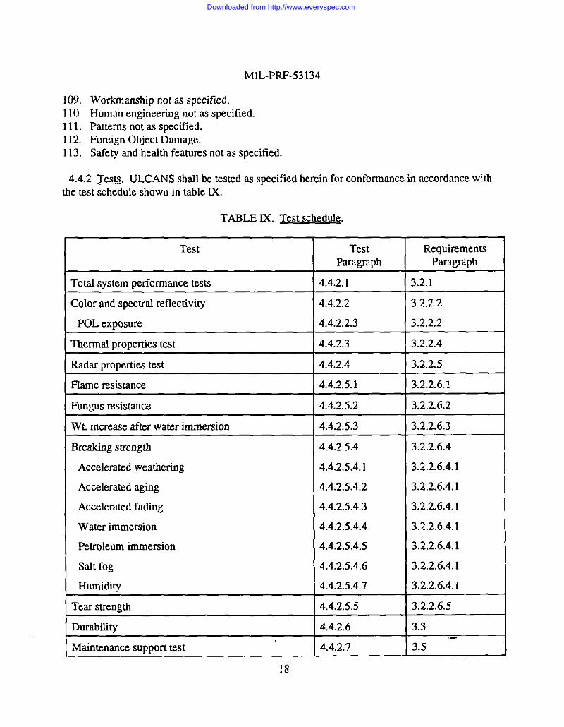
4.4.2 ~. ULCANS shall be tested as specified herein for conformance in accordance withthe test schedule shown in fable IX.
TABLE DC. Test schedule,
Test Test RequirementsParagraph Paragraph I
rotal system performance tests 4.4.2.1 3.2.1
Color and spectraf reflectivity 4.4.2.2 3.2.2.2
POL exposure 4.4.2 .2.3 3.2.2.2
Tltermaf properties test 4.4.2.3 3.2.2.4
Radar properties test 4.4.2.4 3.2.2.5
flame resistance 4.4.2.5.1 3.2.2.6.1
Rmgus resistance 4.4.2.5.2 3.2.2.6.2
Wt. increase after water immersion 4.4.2.5.3 3.2.2.6.3
Breaking strength 4.4.2.5.4 3.2.2.6.4
Accelerated weathering 4.4.2.5.4.1 3.2.2 .6.4.1
Accelerated aging 4.4.2.5.4.2 3.2.2 .6.4.1
Accelerated fading 4.4.2 .5.4.3 3.2.2.6.4.1
Water immersion 4.4.2 .5.4.4 3.2.2 .6.4.1
Petroleum immersion 4.4.2 .5.4.5 3.2.2 .6.4.1
salt fog 4.4.2 .5.4.6 3.2.2 .6.4.1
Humidity 4.4.2 .5.4.7 3.2.2.6.4.1
Tear strength 4.4.2.5.5 3.2.2.6.5
Durability 4.4.2.6 3.3
Maintenance support test 4.4.2.7 3.5 –
18
Downloaded from http://www.everyspec.com
MIL-PRF-53 134
4.4.2.1 Total svstem Performance tests. The Government will conduct the followingperformance tests. Any system failure for any of these tests is reason for rejection.
4.4.2.1.1 Erection time.
4.4.2 .1.1.1 ULCANS tvoes I and II. After reading the technical manual and inventorying thesystem, three experienced soldiers will deploy the system within the time specified in 3.2.1.1.1.
4.4.2 .1.1.2 ULCANS tVOes fU and IV. After readiog the technical manuals and inventoryingthe systems, three experienced soldiers shall assemble (connect) two ULCANS systems (twohexagon screens and two rhombic screens) and deploy the systems. The same three soldiers shallthen assembly and deploy two LCSS systems in the same configuration. Each exercise shall betimed from the opening of the containers until the soldiers are clear of the deployed systems. Thetimes shafl then be compared and Nonconformance with 3.2.1.1.2 shafl constitute faihm of thistest
4.4.2 .1.2 Removal times.
4.4.2 .1.2.1 ULCANS tw e 1and Il. The three experienced soldiers, who erected the types I/IIsystems, will rake it down as spec~led in 3.2.1.2.1.
4.4.2.1.2.2 ULCANS tvDexIll and IV. Three experienced soldlers will break down and storetwo connected ULCANS systems (two hexagon screens and two rhombic screens). The samethree soldiers shall then break down and store two LCSS systems in the same configuration.Each exercise shrdl be tinted from the beginning of break down until soldiers have packed allcomponents intn storage containers. ‘llre times shall then be compared and Nonconfomtatrcewith 3.2.1.2.2 shall constitute failure of this test.
4.4.2.1.3 Environmental conditions. ULCANS shafl be tested under the following conditions.Any system failure is reason for rejection.
4.4.2.1.3.1 w. After deployment, ULCANS shall be subjected to a steady wind of 25 mphor greater with 10 gusts of 46 mph or greater during a two-hour period. Nonconformance to3.2.1.4.5 shall constitute failure of this test
4.4.2 .1.3.2 Freezirw rairr/fce. Support components shall show no signs of structural safety oroperability degradation when subjected to ice and freezing rain tests, guidance MIL-STD-8 10,method 521. Nonconfomrance to 3.2.1.4.4 shall constitute faifure of this test.
4.4.2 .1.3.3 Sand/Dust. Support components shall show no signs of structural, safety, oroperability degradation when subjected to sand and dust tests, guidance MIL-STD-8 1(%method510. Nonconformance to 3.2.1.4.4 shall constitute faifum of this test.
19
Downloaded from http://www.everyspec.com

MIL-PRF-53 134
4.4.2.1.4 Environmental tests. ULCANS components shall be subjected to extreme climaticconditions in an environmental laboratory guidance MfL-STD-810. Function of all componentsshalI not be adverseiy affected.
4.4.2.2 Color and srrectrat reflectivity.
4.4.2.2.1 Color testing. Samples of finished camouflage screen material measuring 1 m(meter) x 1 m are required for color testing. A sample is required for each color present in thescreen pattern.
4.4.2 .2.1.1 Test arroaratus. A spec~oradiometer meedng parameters specified in table X isrequired.
TABLE X. Radiometer rxarameters.
Bandpasst=10 nmSampling IntervalK=5 nmAcceptance Arrgle>=5 degree~’Seositivity+=lO-g W/cm’Spectral Range 380-780 nmWavelength Accuracyz=l nmWavelength Repeatability+O.5 nm
it cone ~ ~g]e>=2.5 degrees.a In native UMNOfthe instrument
The room where the measurements are made shalf be painted matte black using paint with anaverage reflectance of 0.05 (5 percent) or less in the range 0.4 to 2.5 microns. Louvered diffuserafor ceiling lamps shafl be painted with the same black paint and dkect the light straight down toprevent entry and reflection of stray tight from the lamps. The floor shall be covered with a blackrubber pebble-grained mat or similar material with a reflectivity simifar to the paint for the walk.All entrances shalf be fight tight to block stray radiation.
Two CfE D65 simulatom shall be used to illuminate the samples. The lamps shall be qualitledby CIE Publication 51 requirements for color rendering with a rating of C or better for both colorand W rating. Lamps shall be used in pairs and each lamp shafl defiver a tilmum of 75 foot-candles of ilfumirration at 0.75 meters. The Iamps shafI be capable of illuminating a 1m x 1 marea with a uniformity of *2Opercent.
20
Downloaded from http://www.everyspec.com

MIL-PRF-53 I34
A fixture is required to support test specimens vertically at the required orientation withoutcreating folds or wrinkfes in the sample. The net specimens shall be mounted on the glossy sideof a l/4-inch thick black acrylic sheet four feet square.
A diffuse white panel of known spectral reflectivity shall be used as a guidance standard. Thepanel sbafl be a primed afrrminum sheet at least 125-inch thick and four feet square, paintedwidr a high quafity, T102-rich matte white paint free of barium sulfate (f3aS0.J and other whitepigments.
4.4.2 .2.1.2 Test omcedure. Four spectraf reflectivity measurements shall be made for each ofthe required screen samples. The screen samples shafl be rotated 90 degrees within the plane ofdie sample between measurements. The screen samples and reflectance standard shalf bepositioned vertically and normal to the fine-of-sight of the spectroradiometer for allmeasrrt-ements.
The lamps shall be angled at 45 degrees (nominal) and positioned as close to each other and themounting fmture as possible without obscuring the field of view of the spectroradiometer orinterfering with production of uniform iUumirtation. The distance from the radiometer to thespecimen shalf permit viewing an area of the specimen at least 0.5 meter in diameter, and shaU bepointed at the cerrter of the specimen position. The height of the instrument aperture, the supportfmttrre specimen mount center, and centers of the lamps shafl aLlbe the same.
Lamp positioning shall be determined with the black acryfic support in place and the mom fightsoff. The lamps shalf be moved untif there is no specular component coming from the blacksupport toward the Iocation of the spectroradiometer.
With the wfthe reference in place, the room lights out and the lamps on, the uniformity of theillumination of the white reference surface shaO be checked by holding a photometer against thereference in sixteen uniformly spaced positions (4X4 grid). As required, maneuver theiffuminators to flatten the field of illumination. Individual departores from uniformity shafl notexceed 20 percent of the average of aOthe readings.
Place the spectroradiometer at a distance that rdlows its view angle to encompass a measurementarea at least 0.5 meter in dk+tneter. Tbe fmrd position of the radiometer shaff be determined byiterative radiometric mapping using a black matte surface for a background. The radiometershaU be pointed at the center of the specimen position. Mapping can be done by holding a small(7.5 watt) lamp at freed grid points and observing and mapping the instrument response. Aftereach mapping the position of the instrument shalf be refined and checked. For this purpose thenative response units of tie uncalibrated radiometer (voltage or current) are an adequate measure.
The preparation of the white reference panel shall include at least two witness coupons, 1 inch by1 inch. The reflectivity of these coupons shalf.be measured in a spectrophotometer referenced toa NfST-traceable standard. Measurements shalf be at 5 nm intervals. The reflectivity, evafuared
21
Downloaded from http://www.everyspec.com

MIL-PRF-53134
between 380 and 750 nm, of the white panel as a function of wavelength is the average value ateach wavelength in the wavelength range. No measured value between 380 and 750 nm shall bemore than 0.003 in reflectivity and the root mean squared (rms) error for all coupons at allwavelengths between 380 and 750 nm shall not exceed 0.005 reflectivity units.
The black panel shafl be positioned and a net specimen attached. Tape may be used to fasten theedge of the netting to the mount. Position the screen sample so that fabric threads rmminglengthwise in the machine direction are oriented horizontally. Pull the screen sample taut toeliminate folds and wrinkles without distorting the scrim or the garnish. Illuminate the screensample, and acquire spectroradiometric measurements. Rotate the screen sample 90 degreeswithin dre plane of the sample and reposition sample over the background plate. Repeat the testprocedure for each of the four sample orientations.
4.4.2 .2.1.3 Calculation of color coordinates. A reflectivity versus wavelengdr function shall be
R(L) = - )?.(k)r
calculated for each of the test specimens using the following relationship:
whereR(?J = test specimen reflectivity as a function of wavelength
Lm) . measured spectral radiance reflected from the test specimen, averaged at eachmeasured wavelength over each of the four sample orientations
L@) = measured spectrrd radiance reflected fmm the reflectance standardand
R~(L) = absolute specmd reflectivity of the reflectance standard for k = 380 to 750 nm
Tristimulus values and CfELAB color coordinates shalI he cafcrdatcd fmm spectral reflectivitydata for each specimen in accordance with ASTM E 308 using standard illumirtant D= and CIE1964 supplementmy standard (10 degrees) observer. Nonconformance to 3.2.2.2.1 shallconstitute faiIure of this test.
4.4.2.2.2 Srrectral reflectivity.
4.4.2 .2.2.1 Test suecimens. Samples of finished camouflage screen materiaI measuring 1m x1m are required for spectml reflectivity testing. A sample is required for each color present inthe screeo pattern.
—
22
Downloaded from http://www.everyspec.com
MfL-PRF-53134
4.4.2 .2.2.2 Test a~~aratus. A spectroradiometer capable of operation over the wavelengthrange 600 to 2500 nm is required for acquisition of radiometric data. Measurements shall beperformed in a darkened room or enclosure having matte black interior surfaces with nonsecularr~ffectivity vafum less than 5 percent over the wavelength range 600 to 2500 nm. Room orenclosure and afl entrances or openings must be must be light tight to block stray radiation. Twobanks of quartz-hafogen lamps or two arrays of lamps having a suitable reflector or lens capableof illuminating a I m x 1m area with a minimum intensity of 50 W/mz is required. Illuminaoceover this area shall be unifontt to within *2O percent of the average vahte. A fmture is requiredto support test specimens vertically at the required orientation without creating folds or wrinkfesin the sample or preventing transmission of light through the sample area. A diffuse whitereflectance standard with dimensions 1 m x 1m having noospectdar reflectivity coated with highgrade Ti02 paint is required for determination of sample spectral reflectivity. A black acrylicflat plate measuring 1m x 1m is required as a background for measurement of test samples.
4.4.2 .2.2.3 Test trrocedure. Four spectral reflectivity measurements shall be made for each ofthe required screen samples. Screen samples shall be rotared 90 degrees witbin the plane of thesample between measurements. Screen samples and reflectance standard shafl be positionedverdcatfy and normrd to the line-of-sight of the spectroradiometer for afl measurements. Theheight of the spectroradiometer aperture, the support fixture specimen mount center, and lampsshalf all be the same.
Two banks of quartz-hafogen lamps shaff be angled at 45 degrees (nomirrrd)‘md positioned asclose to the mounting fixture as possible without obscuring the field of view of thespectroradlometer and without interfering with production of a uniform iflumioation over a 1 m x1m area. Lamp positiorrirrg shall be determined with the black support in place and the roomfights off. The lamps shall be moved until there is no specular component coming from the blacksupport toward the spectroradiometer.
Place tbe spectruradiomerer at a distance that allows its view angle to encompasses ameasurement area at least 0.75 m in diameter. The final position of the radiometer shalt bedetermined by iterative radiometric mapping to ensure that the radlomerer shalf be pointed at thecenter of the specimen position. Mapping shall be done by holding a 7.5 watt [amp against ablack mat background at freed grid points and mappitig the instrument response. After eachmapping the position on the instrument shall be refined aad checked. For this purpose the nativeresponse units of the uncalibrated radiometer (voltage or current) are art adequate measure.
Aquire spectroradiometric measurements of reflectance standard over the wavelength range 600to 2500 nor with a maximum iotervaf of 20 nm between measurements. Replace the reflectancestandard with bIack background plate and attach a screen sample. Position the screen sample sothat fabric threads running Lengthwise in the machine direction are oriented horizontally. Poll thescreen sample taut to eliminate folds and wnokfes witbout distorting the scrim or the garnish.Illuminate the screen sample, and acquire spec,troradiometric measurements as beforelor thereflectance standard. Rotate screen sample 90 degrees within the phrte of the sample and
23
Downloaded from http://www.everyspec.com

M[L-PRF-53 134
reposition sample over the background plate. Repeat the test procedures for each of the foursample orientations.
4.4.2 .2.2.4 Calculation of srrectral reflectivity. A reflectivity versus wavelength function shrdlbe calculated for each of the test specimens at each of the four sample orientations using the
following relationship:
where
R(Z) = test specimen reflectivity as a function of wavelengthL@) = measured spectral radiance reflected from the test specimenI,@) = measured spectral radiance reflected from the reflectance standard
and
lqd(z) = absolute spectral reflectivity of the reflectance standard for L = 600 to 2500 nm.
Nonconformance to 3.2.2.2.2 shall constitute faihrre of this test.
4.4.2.2.3 POL exposure for color test. Appropriate size and number of samples as required by4.4.2.2.1 and 4.4.2.2.2 shrdfbe prepared for POL exposure. Separate samples shaIl be preparedfor helicopter fuel W-8 and diesel fuel DF-2. Immerse test sample for 15minutes in fuel.Remove and blot excess liquid from screen. Samples shall be rested as specified in 4.4.2.2.1 and4.4.2.2.2. Nonconformance to 3.2.2.2 shall constitute faihrre of tfds test.
4.4.2.3 Thermaf properties test.
4.4.2.3.1 Thermal transmission. Themral transmission testing shall be performed indoors.Two heated plate targets, each having art area of at least 10 feet square (10 ft’), shalI be heated totemperatures of 25 *2 “C and 40*2 “C respectively, above ambient air temperature. Targettemperatures shaIl be maintained to witbin 0.5 “C of these vafues throughout the testing.Imagery of each tmget in the 3 to 5 and 8 to 12 micron band shalt be acquired with targets fallingthe imagers’ field of view and average radiance levels for each of the targets shall be determined.The finished ULCANS shalf then be suppo~d so that a single layer of material hangs verticallyat a distance often feet in front of both targets. ‘flrermat imagery of that portion of the ULCANSwhich conceals each of the targets shall be acquired and average radiance levels for each of the10 ft’ minimum sectioos of material which covers each target shall be determined. Thepercentage transmission shall be calculated as follows:
24
Downloaded from http://www.everyspec.com

Where R = Radiance levelU = ULCANS covered targetB = Bare target40= Target 40 “C above ambient air temperature
and 25 = Target 25 “C above ambient air temperature
The ULCANS shall be repositioned so that a different area of the screen conceafs the targeta afterimagery of the bare targets is reacquired and the above procedure shaIl be repeated. A total offive measurements shrdl he made to obtain an average transmission value for tire ULCANS.Nonconformance to 3.2.2.4.1 shall constitute failure of this test
4.4.2.3.2 Screen thermal sienature. Screen thermal signature testing shall be performedoutdoors. The ULCANS shall be deployed in its intended cofilguration in an open area so that itreceives full solar radiation in daytime. frnagery of the ULCANS in the 3 to 5 and 8 to 12micmnband shrdl be acquired during the day after exposure of the screen to solar radiation levels greaterthan 800 W/mz and an average wind speed of less than 2 M/s for a period of at least one hour.The imager shall be positioned at ground level so that those screen surfaces which receive thegreatest solar Ioadmg are in the imager’s field of view. An ambient temperature black bodyhaving art emissivity of 0.98 or higher in the 3 to 5 and 8 to 12micmn band shall be placed in tieimager’s field of view at the same distartw fmm the imager as the ULCANS and shieIded fromincident solar radiation. Ambient air temperature shall be determined by measuring aCNd
ambient black body temperature. Daytime thermal imagery shall be collected while the solarradiation level is greater than 800 W/mz and the average wind speed is less thao 2 mfs. Imagetyof the ULCANS shall be acquired at three different times with a period of at least 15 minutesbetween readings. Ambient black body temperature shall be used as a reference point incalibrating the imagery. Daytime imagery shall be anafyzed to identify the 1m 2area of theULCANS which has the highest average apparent temperature. Vkurd inspection of imagerymay be used to limit the anafysis to those regions of the ULCANS which appear to have a highaPP~ent temPerWnre relative to the rest of the screen. The dlfferenw between the averageaPPment @mPem~~ of this area and ambient air temperature shafl be determined for eachreading and these values shall be averaged. hnagery in the 3 to 5 and 8 to 12micron band shallrdso be acquired at night while there is minimal cloud cover (less than ten percent). The windspeed specified for daytime testing does not apply to nighttime testing, however, wind speedshafl be recorded. An ambient temperature black body shaff be used to determine ambient airtemperature and calibrate imagery as in the daytime test. Nighttime imagery of the ULCANSshall be acquired at three different times with a period of at least 15 minutes between readings.Nighttime imagery shall be arrafyzed to identify the 1mz area of the ULCANS which has thelowest average apparent temperature. Visual inspection of imagery maybe used to limit rlreanafysis to those regions of the ULCANS which appear to have a IOW appwent @mPe_m~rerelative to the rest of the screen. The difference between the avetage apparent temperature of this
25
Downloaded from http://www.everyspec.com

MfL-PRF-53134
area and ambient air temperature shafl be determined for each reading and drese values shall beaveraged. Nonconformance to 3.2.2.4.2 shall constitute failure of this test.
4.4.2.4 Radar motrerties test. Average percent power transmitted through a finished net shallbe measured at two orthogonal antenna pnlanzations relative to the screen and at least51 discretefrequencies over a bandwidth of 2 GHz centered at 6.0, 10.0, 17.0,35.0, and 94.0 GHz using theprocedure outlined in 4.4.2.4.1. The standard deviation and correlation length shall be measuredat 10 GHz using the procedure outlined in 4.4.2.4.2. Nonconformance to 3.2.2.5 shall constitutefailure of tits test.
4.4.2.4.1 Averaee transmission test.
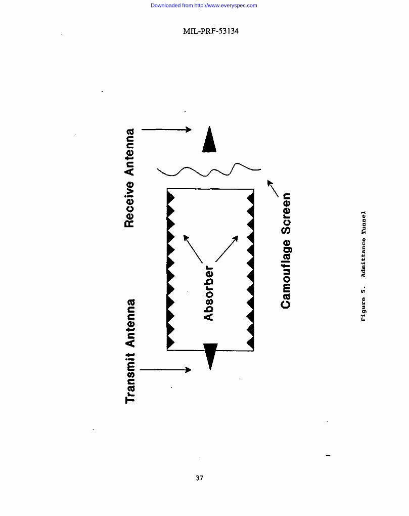
4.4.2 .4.1.1 Admittance tunneL Construct admittance tunnel as shown in figure 5. The interiorof the tunnel shatl be coated with radar absorbing material. The dimensions of the tunneI sbafl besuch that the tunnel aperture is in the far field of all antennas used in the measurements. Theaperture of the tunnel sbafl provide at least 625 square inches of area unoccluded by any radarabsorbing materiat.
4.4.2 .4.1.2 Calibration. At each discrete frequency and polarization measure and record thecomplex voltage response of tfte admittance tunnel with no screen covering the aperture. Storethis data for use in the cafcrdations outlined in 4.4.2.4.1.4. A new set of calibration data sbrdl betaken for each screen measured.
4.4.2.4.1.3 Screen dats. Take screen data as folfows: Stretch screen tightly over tunnelaperture so that continuous contact is made on all four edges of the aperture and no obvious foldsor heavy wnokfes are evident. Measure and record complex voltage response of the screen.Repeat this procedure six times per frequency and relative polarization with a different section ofscreen positioned over tunnel each time.
4.4.2 .4.1.4 Crdculations. Cafculate percent power transmitted for each sample, polarization,
T.., = Iv’(i’j’k) ? xIOO% i=l,2,... i{ j=l,2,...6 k=l,2uV,(i, k)
and discrete frequency using the folfowing formulas:
where
Tijk = percent power transmitted for sample.Vc(i,k) = complex voltage response of the open
rneasrrred in 4.4.2.5.1.
26
and frequency i at polarization k.unnel at frequency i and polarization k
Downloaded from http://www.everyspec.com

V,(i,j,k) =
N .
MIL-PRF-53134
complex voltage response of screen for sample j, frequency i, and polarization kmeasured in 4.4.2.4.1.3.Number of discrete frequencies.
The resulting vahres of T for each polarization and each band are averaged by sample number
and frequency to obtain the average T by the foifowing formula.
where ~>~ is the average transmission at polarization k.
4.4.2.4.2 Standard deviation and correlation length test..4.4.2 .4.2.1 Scanning aomrmtrs. An apparatus for linearly positioning an open ended X band
(WR-90) waveguide at any arbitrary location in the aperture plane of the admittance tunnel ofsection 4.4.2 .4.1.1 shall be constructed. The scanning apparatus replaces the receiving antenna infigure 5. The apparatus shall be capable of accurately positioning tfrewaveguide to within.O1-inch. The open end of the waveguide shall be positioned as close as possible to the aperturewithout making physical contact with aoy camouflage material covering the aperture.
4.4.2 .4.2.2 Calibration. Wltb no materiaf covering the aperture, measure and record firecomplex voltage response from the open waveguide as it is scanned in I&inch steps across theaperture of the admittance tunnel with the transmitter operating at 10 GHz. The open waveguideand the tmtsmitting antenna shall have the same polarization. The linear extent of the scan mustbe within the haff power points of the tunnel aperture and shall be at least 25 inches.
4.4.2 .4.2.3 Scan data. Take scan data as foltows: Stretch screen tightfy over tunnel aperture sothat continuous contact is made on all four edges of the aperture and no obvious foIds or heavywrinkfes are evidenL Measure and record the complex voltage response of the screen as thewaveguide is scanned across the material in .10-inch steps over the length of the scandetermined in 4.4.2.4.2.2. Repeat this procedure six times with a different section of screenpositioned in front of the waveguide each time. Screen samples shrdf be rotated 90 degreeswithin the plane of the sample between measurements.
4.4.2 .4.2.4 Calculations. Tire calibrated transmission at each position of the scan is calculated
Iv,(i, j) ~Tu =Iv=(i) 1’
i = 1,2... N j= 1,2,...6
using the folfowing formula.
27
—
Downloaded from http://www.everyspec.com
MIL-PRF-53 134
where
N= the number of data points per scan.V,(ij) = the measured complex response of the screen sample j at position i,V=(i) = the meaxured calibration value at position i.
v=
R. =E~I~7.,(Tv - F){ Tq - ~) k=i+n
The autocovariarrce function of the scan is then computed by the foUowirtg formula.
To obtain a correlation lengti of less than 2 inches, the screen data must then meet the folfowing
condition.
where e is Euler’s number (approximately 2.71828).
4.4.2.5 Screen materird Dmuerties tests.
4.4.2.5.1 Ffame resistarrce. Test specimen shall be prepared by using a 12-inch x 12-inch pieceof screen. Specimens shall not be selected from the same roll. Each specimen shall beconditioned according to option B of ASTM D 3659. Each specimen shaff be attached to andhung from a horizontal support so drat the entire 12-inch x 12-inch area is exposed. The middleof the bottom edge of the specimen shafl be positioned in the center of a 1-1/2 inch burner flame.
28
Downloaded from http://www.everyspec.com
MfL-PRF-53 134
The burner, gas regulator vrdve, and fuel shall be as specified in ASTM D 3659. The flame shallbe applied for 15 seconds then removed. Nonconformance to 3.2.2.6.1 shall constitute failure ofthis test.
4.4.2.5.2 Furwrrs resistance. The screens shall be tested in accordartce with ACT 30, test III.Nonconformance to 3.2.2.6,2 shaU constitute failure of this test.
4.4.2.5.3 Weight increase after water immersion. For guidance use FED-STD- 191, method5502 to determine the screen weight increase after immersion in water. A 6 x 6 inch sampleshalf be used. Nonconformance to 3.2.2.6.3 shalI constitute failure of this test.
4.4.2.5.4 Breaking streneth. The breaking strength of the garnish cloth and woven screenmaterial shall be tested in accordance with ASTM D 5034 grab test method. The breakingstrength of the knitted screen material shall be tested in accordance with ASTM D 3787 burstingbafl test method. Nonconformance to 3.2.2.6.4 shall constitute failure of this test.
4.4.2 .5.4.1 Accelerated weathering. The material shaU be conditioned in accordance withASTM G 26, method 1, type BH for 300 hours and tested as specified in 4.4.2.5.4.Nonconformance to 3.2.2 .6.4.1 sbrdl constitute failure of this test.
4.4.2 .5.4.2 Accelerated atzing. The materird shall be conditioned in accordance with ASTM D751, test method: accelerated heat aging of fabrics coated with robber or plastics by the ovenmethod, for ten days at 175 M “F, and tested as specified in 4.4.2.5.4. Nonconformance to3.2.2 .6.4.1 shaff constitute failure of this test.
4,4.2.5.4.3 Accelerated fading. The material shalf be conditioned for 140 hours, guidanceFED-STD-191 method 5660, sod tested as specified in 4.4.2.5.4. Nonconformance to 3.2.2 .6.4.1shall constitute failure of thk test.
4.4.2 .5.4.4 Water immersion. The ftished cloth shall be immersed in distilled water for 24hours at 73 ~ “F, and tested as specKled in 4.4.2.5.4. Nonconformance to 3.2.2.6.4.1 shaIfconstitute failure of thk test.
4.4.2 .5.4.5 PeEoleum immersion. The ftihed cloth shall be immersed in both JP-8helicopter and DF-2 diesel firefs for 2 hours at 73 *2 “F, and tested as specified in 4.4.2.5.4.Nonconformance to 3.2.2 .6.4.1 shalf constitute faifure of this test
4.4.2 .5.4.6 Salt fop. The finished cloth shalf be conditioned for 300 hours in accordance withASTM B 117 and tested as specitied in 4.4.2.5.4. Nonconfomrance to 3.2.2.6.4.1 shalf constitutefailure of this test.
29
Downloaded from http://www.everyspec.com
MIL-PRF-53134
4.4.2 .5.4,7 Humidity. The finished cloth shall be conditioned for 14 days in accordance withASTM D 2247 and tested as specified in 4.4.2.5.4. Nonconformance to 3.2.2 .6.4.1 shatlconstitute failure of this test.
4.4.2.5.5 Tear strength. The garnish cloth material shrdl be tested in accordance with ASTM D2261 except with the following mod~lcations:
a. The specimen size shall be I inch by 8 inches.b. ‘fIre rest shall be performed only with specimens with the short distance (l-inch width)
parallel to the warp yams.c. The average break value shafl be calculated based on the average of the five highest peaks
of each sample tested.
Nonconfomrrmce to 3.2.2.6.5 shall constitute failure of this rest.
4.4.2.6 Durability. ULCANS shall be deployed rmd recovered into storagehransport containers112 times. Nonconformance to 3.3 shalt constitute a faiture.
4.4.2.7 Maintenance srruPort test. Prior to conducting Government verification performancetests, make an “L shaped incision in screen 24 inches in each direction (each Ieg) and repair withitems in repair kit. At end of test arty evidence of screen deterioration in the repaired area isreason for rejection.
5. PACKAGING
5.1 Packa~ing. For acquisition purposes, the packaging requirements shall be as specitled inthe contract or order (see 6.2). When acmaf packaging of materiel is to be performed by DoDpersonnel, these personnel need to contact the responsible packaging activity to ascertainrequisite packaging requirements. Packaging requirements are maintained by the InventoryControl Point’s packaging activity within the Militag Department or Defense Agency, or withinthe Mtitary Department’s System Command. Packaging data rernevaf is available form themanaging Military Department’s or Department Agency’s automated packaging tiles, CD-ROMproducts, or by contacting the responsible packaging activity.
6. NOTES.(This section contains information of a general or explanatory nature that maybe helpful, but isnot mandatory.)
6.1 Intended use. ULCANS is the camouflage system designed fnr use with all militarymateriel isrchrding racticat vehicles and aircraft ULCANS is the only camouflage screen systememployed by aviation units to camouflage aircraft. It is intended to increase vehicle survivabilityby countering visual, wide band radar, near infrared and thermal detection capabititie& Duringhigh winds and heavy snowfalls, ULCANS should be checked frequently. A great accumulation
30
Downloaded from http://www.everyspec.com

MIL-PRF-53 134
of snow or ice should not be allowed to accumulate on screens. Snow or ice must be removedfrom the screens as soon as they begin to sag or show signs of stress or strain due to the extraweight.
6.2 Acquisition recmiremerrrs. Acquisition documents should specify the foUowing:
a. Title, number, and dare of the specification.b. Issue of DoDISS to be cited in the solicitation, and if required, the specific issue ofindividual document referenced (see 2.2 and 2.3).
c. When a first article is required for inspection and approval and number of units required (see3.10 and 4.2).
d. Packaging requirements (see 5. 1).e. Marking if other than as spec~led (see 5.2).
6.3 Definitions.
6.3.1 ULCANS @e I. Ultmdightweight Camouflage Net System, type I consists of thecomponents (modular camouflage screens, rotor blade tip covers, wire cutter covers, repair kit,operators and maintenance mamraf, and storagehrtsporr containers) required to conceal anOH-58D helicopter.
6.3.2 ULCANS tvPCIL Ukralightweight Camouflage Net System, type II consists of thecomponents (moduIm camouflage screens, rotor blade tip covers, wire cutter covers, repair kit,operatora and maintenance mamraf, and storageltransport containers) required to conceal anAH-64 or UH-60 helicopter.
6.3.3 ULCANS tvpes HI rmd fV. Ultralightweight Camouflage Net System, types III and fVconsists of the components (modular camouflage screens, repair kit, operators and maintenancemanual, and storagehmrrsport containers) required to conceal ground equipment.
6.3.4-. The terms “net”,” netting” and “screen” are synonymous in this specification.
6.3.5-. The act of emcdrtg ULCANS, fmm the storage case being opened until Liesoldiers wafk clear of tie ULCANS.
6.3.6 Recover. ‘fire act of taking dnwn ULCANS and putting it in the storage containers withall components clear of equipment or aircraft. Types I and tI shalf be secured and aircraft able todepart &fely.
6.3.7 Concealment.
6.3.8 Iderrtitlcation.ULCANS.
Hiding an airvraft or vehicle under an ULCANS.
Ability to determine the presence of an aircraft or vehicle under ~
31
Downloaded from http://www.everyspec.com

MIL-PRF-53134
6.3.9 Open storaee. A covered storage area without environmenttd control (i.e., hangar.warehou~, etc.).
6.3.10 Experienced soldier. Any soldier that has deployed ULCANS a minimum of 3 times.
6.3.11 .Swstemfailure. A system failure is defined as any malfunction that can not be repairedby the crew and which causes or may cause failure to commence operation, cessation ofoperation or degradation of performance below specit3ed levels or poses serious personnel safetyhazards.
6.3.12 Service life. Service life shall be considered 112 cycles.
6.4 Subiect term fkev word) listirw.
concealmentnear infrared suppressionnettingradar suppressionscreenscreeningthermal suppressionvisual suppression
Custodians:Army-MENavy - MC
Preparing activity:Army-ME
Project 1080-0083
—
32
Review activities:Army - AV, CR, GL, MI
Downloaded from http://www.everyspec.com
I
w cd
I
‘““-t--—
-”~u
‘3+
DONO
TSC
ALE
FROM
THES
ESK
ETCH
ES
Ialss i z .s,
4. 5.
SIMS
LOWSMU
ESLO
XSO
ATCO
RKRS
MO
SNJIl=lW!l.Y
SPUX
OUJJNCfMX91X
AlA
UAxw
wMNm
llor
FMm
ONCnm
R.
mhu3ERm
mmo.
Wxlm
mg
~wgfm
JowM
W.ws
mu
~“~bmm?i
NI[
mu
mu
Iwf.s
Aif
UL
uNf.16?oN
5Nrsll.
Eia
COLO
RCO
DES
NOCO
LOR
1BU
CK2
UGW
GREE
N3
FOR~
GRE
EN
Figure
1.ULCANSType
I
Downloaded from http://www.everyspec.com

NJlm
DONO
TSC
ALE
FROM
THES
ESK
ETCH
ES
1. 2. 3, 4. 5.
ulsMslER
mnncm
Eff~
*W=
mmm
Plus
wEs
NltWNS
LU6N
JEL
r=.
eCOLO
RC1
20+3
NOCO
LOR
1EU
.CK
2mm
GIWEM
3fozfzl
GRm
Fi~@
2.ULCANSType
II
Downloaded from http://www.everyspec.com

Eiiiii3
--1
19=i7-
,
I
~ z da
w g
DO
NOT
SCALE
FROM
THES
ESK
ETCH
ES
00NOT
SCU
FROM
THES
ESK
EfCH
ES
Figure
3.
ULCANS
Types
III
&IV
Downloaded from http://www.everyspec.com

I
w m
TOP
RETA
INER
PIAT
E
/
(NON
-RAO
ARRU
LE~N
GM
ATE
RIA
l)
rYA
:2’;
’’””
)“=%{-”-”~i,-
\.-
.m“
1.YY
L.vI
03.0
0
Figure
4.
Antema
Flange
Assembly
Downloaded from http://www.everyspec.com
w u
Antenna
Receive
Antenna
1 +
/’Absorber
\
Camouflage
7
Screen’
I
Figure
5.
Admittance
Tunnel
Downloaded from http://www.everyspec.com
STANDARD12A: 10N 00CWSENT IMPROVEMENTPROPOSAL
INSTRUCTIONS
1. The preparing activity oust cmpiete blocks 1, 2, 3, and 8. In block 1, both the docent nmber ad reVi SiOn letter shouhbe give”.
2. The submitter of this form rust c.mp(ete b(ocks 4, 5, 6, md 7.3. The prepwing activity mnr provide a reply within 30 days frm receipt of the form.
NOTE: This form may not be used t. request copies of docments, nor to request waivers, or clarification of rswirmsnts mcurrent cmtr.acts. Ccmnents sutfnit ted m this form do not constitute or itrply author izatim to uaive anv portion of thereferenced dacunm t(s) or to amnd contractual rsquirenmts.
RECCWENDA CHANGE: 1. DOCUMENTNUMBER 2. OIXWENT DATE (YYN14DD)MI L-PRF -53134 960126
3. DOW!(ENT TITLE uLTmLIGHTkiEIGHT CAJ4CUFLAGENET SYSTEM (ULCANS)
4. NATUREOF CHANGE(Identify paraLTraFAI rnmber md include prapossd rewrite, if possible. Attach extra sheets as needed. )
5. REA2DN FOR RECC+OIENDATION
5. 5USHITTER
>. NM (Last, First, ❑i&le Initial> b. 0RGAN12ATIDN
:. AOORESS(lnckde Zip Cede) d. TELEPHONE (Inc(uds Area code) 7. DATE SIISHITTEO(1) Cmnw-cial
(if a@icable)(2) DSN
]. PREPARINGACTIVITY
1. NmE b. TELEPHONE (Include Area Cede)(1) Camercie,t (2) DSN 654-366s
Carolw S. Johnsm (703) 704-3469
:. ADDRESS(Include Zip C&) IF YUJ 00 NOT RECEIVE A REPLY WITHIN 45~AYS, CO#lACT,OEFNS QLTY 8 STOZN OFC
USA CCW4UNICATIWS-ELECTRONICS WC), BELWIR PIPE 2CUTH 52o3 LEESSURGPIKELDGISTICS & REAOINESS CENTER STE 1403ATTN: AMSEL-LC-ED-SO FLS CHURCHVA 22041-3464FT BELVOIR VA 22060 -5S49 Tele@mne (703) 736-234o OSN 289-2340
Downloaded from http://www.everyspec.com