mike richards looks at the sdrplay radio spectrum ... · the mirics chipset is very easy to...
TRANSCRIPT
8 December 2014 radiouser
■ Mike Richards looks at the SDRplay Radio Spectrum Processor
■ All images and diagrams supplied by the author
review
T he SDRplay Radio Spectrum Processor (RSP) is a completely new offering and the fi rst from
this company. Designed to provide as wide a frequency coverage as possible, while giving the user access to a wealth of internal adjustments, the RSP looks an attractive proposition. The package also includes the documented application programming interface (API) that will enable more advanced users to create their own receiver and decoding designs. Frequency coverage is near continuous between 100kHz and 2GHz and the receive in-phase and quadrature (IQ) bandwidth can be adjusted from 200kHz up to 8MHz with 10-bit resolution.
In the BoxThe SDRplay RSP is supplied in a compact housing measuring 30 x 80 x 110mm with just two connectors. The
Let’s run through the operation. Frequencies in the range 0 to 60MHz are fed through three software selectable inductor/capacitor (LC) filters before being applied to the amplitude modulation (AM) port 2 of the MSi001. The filter bands are 0 to 12MHz, 12 to 30MHz and 30 to 60MHz. For frequencies above 60MHz, the antenna signal is first applied to an enhancement mode pseudomorphic high electron mobility transistor (E-pHEMT) based low noise amplifier (LNA) block to provide around 20dB gain. Following the LNA, a group of five software selectable filters is used with the following ranges: 50 to 120MHz, 120 to 250MHz, 250 to 380MHz, 400 to 1000MHz and finally, a 1000MHz high pass filter. The filter outputs are fed to the appropriate input ports of the MSi001, where each signal is further amplified before being sent to the mixer, filter and final amplifier stages. The final stages in the MSi001 tuner chip generate the differential analogue IQ outputs ready for further processing. The MSi001 also features digital control of the gain stages from the LNA through to the mixer, with an adjustment range of 0 to 59dB in 1dB steps. The SDRplay RSP uses the gain control system to provide its radio frequency/intermediate frequency (RF/IF) automatic gain control (AGC).
The IQ signals from the MSi001 connect to the analogue to digital converter (ADC) in the MSi2500 USB interface device, where the digitised IQ signals are conditioned by the MSi2500’s digital signal processing (DSP) module. The processed IQ signals are finally passed to the SDR software via the USB link.
In addition to providing a complete signal handling solution, the Mirics chips both use a serial peripheral interface (SPI) for the command and programming interface. SPI is a very well-established serial communication system that is easy to use and ideal for this type of
Mike Richards takes a close
look at the SDRplay RSP, a
new SDR receiver hardware
package that features wide
frequency coverage and
has been produced with
experimenters in mind.
SDRplay Radio Spectrum Processor
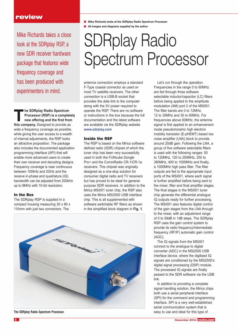
The SDRplay Radio Spectrum Processor.
antenna connection employs a standard F-Type coaxial connector as used on most TV satellite receivers. The other connection is a USB-B socket that provides the data link to the computer along with the 5V power required to operate the RSP. There are no software or instructions in the box because the full documentation and the latest software are available via the SDRplay website.www.sdrplay.com
Inside the RSPThe RSP is based on the Mirics software defined radio (SDR) chipset of which the tuner chip has been very successfully used in both the FUNcube Dongle Pro+ and the CommRadio CR-1/CR-1a receivers. This chipset was originally designed as a one-stop solution for consumer digital radio and TV receivers but has proved to be ideal for general-purpose SDR receivers. In addition to the Mirics MSi001 tuner chip, the RSP also uses the Mirics MSi2500 USB interface chip. This is all supplemented with software switchable RF filters as shown in the simplified block diagram in Fig. 1.
SDRPlay Review.indd 8SDRPlay Review.indd 8 05/11/2014 11:5205/11/2014 11:52

radiouser December 2014 9
tuner sub-system. All the switching and adjustable features of both chips can be accessed through this simple interface that is made available to the host PC via the USB port.
The team at SDRplay has been very open with its design, and full circuit diagrams, technical descriptions and details of the API are readily available on the SDRplay website.www.sdrplay.com
SDR# OperationWhile it’s great to have a flexible design to experiment with, I suspect most people will also want to be able to use the RSP as a practical receiver straight out of the box. To support this, SDRplay supplies an easy to install SDR# plug-in for the RSP. When I ran the installer, it asked me to specify the location of my SDR# software and it then automatically unpacked the plug-in to that directory. On starting SDR#, the RSP plug-in was automatically recognised and selectable via the Source drop-down menu. Fig. 2 shows SDR# and SDRplay receiving a 6MHz bandwidth.
The initial plug-in was short on features but the team at SDRplay is actively working to improve it and made significant improvements during the review period. At the time of writing, the latest plug-in was v1.3 but the team was busy working on a 1.4 release so look out for that.
In addition to providing control of the receiver parameters, the SDRplay plug-in also includes an RF AGC system. One of the benefits of using the Mirics chip to handle the USB conversion is access to a range of receive bandwidths. The default setting was 1.536MHz but the
following bandwidths were selectable from the control panel: 200kHz, 300kHz, 600kHz, 1.536MHz, 5MHz, 6MHz, 7MHz and 8MHz. As you can see from Fig.3 ,
the SDRplay control panel provides a simple block diagram of the receiver, with the bandwidth and gain settings for each stage clearly displayed. When I
Filterswitching
Filterbanks
3 bands 0-60MHz
3 bands 50MHz - 1GHz+ 1GHz HP filter
Mirics MSi001tuner
AntennaMirics MSi2500USB interface
AnalogueIQ
I I
Q Q
DigitalIQ
USB
SPI - controlGPIO
To PC
LNA
+20dB
Fig. 1: A simplified block diagram of the SDRplay RSP.
Fig. 2: The SDR# start-up display.
Fig. 3: The SDRplay control panel in SDR#.
SDRPlay Review.indd 9SDRPlay Review.indd 9 05/11/2014 11:5205/11/2014 11:52

first tried the SDRplay, I was caught out by the unusual action of the AGC. When the AGC is active, it alters various gain settings to avoid ADC overload and the changing gain settings can be viewed in the control panel. However, when you disable the AGC, rather than reverting to a default value, the gain settings remain at the last value set by the AGC system. This is a deliberate plan that’s designed to give the user a good starting point for any manual adjustment. Although unusual, this is a sound idea because it’s very easy to get in a mess when you start altering the gain distribution and bandwidth settings in a complex tuner. By using the AGC to get you in the right area, you stand a much better chance of actually being able to make an improvement. If you do get in a mess, the control panel has a Load Defaults button to put everything back to the default value. One of the other effects of the SDRplay AGC system will be particularly noted on quieter bands. When there are few signals around, the AGC will increase the RF gain to bring the strongest signal in the bandwidth close to 0dB. As a result, the noise floor will also be elevated and it was not unusual to see the noise floor showing at -30dB. It must be remembered that the dB indications in SDR# are not absolute values, so a noise indication at -35dB does not mean -35dBm.
Broadcast ReceptionThe SDRplay RSP supports the reception of frequency modulation (FM) and digital broadcast services and this is best done using the free Mirics software that’s available for download from the SDRplay website – see Fig. 4. This was a simple to use program that included fully automated searches for analogue FM and digital audio broadcasting (DAB) services. This software worked seamlessly and delivered good quality reception complete with radio data system (RDS) and DAB text services. In this configuration, the tuner appeared to be very sensitive.
For ExperimentersIf you want an SDR hardware platform to experiment with, then the SDRplay RSP is not a bad choice. The Mirics chipset is very easy to configure using the SPI link and the hardware performance is well established. The RSP hardware provides the additional switchable RF filters that should allow the unit to operate successfully as a self-contained test-bed
for your experiments. To help configure the Mirics chipset, SDRplay is expecting to be able to supply the Mirics SDR API
Evaluation Tool as a download from its website – see Fig. 5. As you can see, the Mirics tool provides easy access to
10 December 2014 radiouser
Fig. 4: The Mirics broadcast reception software.
An inside view of the SDRplay Radio Spectrum Processor.
SDR Play Specification SummaryFrequency coverage 100kHz to 380MHz and 430MHz to 2GHzIntermediate frequencies Zero IF, 450kHz, 1.620MHz and 2.048MHz
(selectable)IF bandwidths 200kHz, 300kHz, 600kHz, 1.536MHz, 5MHz, 6MHz,
7MHz and 8MHzADC sample rate 0.5 to 12MSPSAntenna 50Ω F-Type connectorUSB USB-2 type B connector
SDRPlay Review.indd 10SDRPlay Review.indd 10 05/11/2014 11:5205/11/2014 11:52

a very wide range of parameters, thus simplifying the development process. ●
radiouser December 2014 11
Fig. 5: The Mirics SDR API Evaluation Tool.
summary
Heil p47.indd 47 27/10/2014 09:29
The SDRplay Radio Spectrum Processor is a great idea that provides a useful, wide frequency range, development platform for those that want to experiment with SDR technology and create their own receive systems. For use as a ready to go receiver, the RSP is still unusual in its approach but I have every confidence that the team at SDRplay will continue development of the SDR# plug-in, thus delivering better out of the box results. Just as this article was submitted, I received news that the popular SDR-Console software could soon support the SDRplay RSP.
The SDRplay Radio Spectrum Processor is available direct from SDRplay and costs £175.00 (including VAT at 20 per cent and shipping). My thanks to SDRplay for the loan of the review model and for its technical support.
SDRplay is a UK company and its registered office is Riverside View, Thornes Lane, Wakefield WF1 5QW.www.sdrplay.com
SDRPlay Review.indd 11SDRPlay Review.indd 11 05/11/2014 11:5305/11/2014 11:53