mil-dtl-24643b superseding mil-c-24643a 14 march 1994...
TRANSCRIPT

INCH-POUND MIL-DTL-24643B 22 August 2002 SUPERSEDING MIL-C-24643A 14 March 1994
DETAIL SPECIFICATION
CABLES AND CORDS, ELECTRIC, LOW SMOKE, FOR SHIPBOARD USE GENERAL SPECIFICATION FOR
This specification is approved for use by all Departments and Agencies of the Department of Defense.
1. SCOPE
1.1 Scope. This specification covers low smoke electric cable and cord for Navy
shipboard applications.
1.2 Classification. Cables and cords covered by this specification are classified as watertight, watertight (with circuit integrity), and non-watertight constructions, armored, and unarmored, unarmored with overall shield and further classified for flexing and nonflexing service for power, lighting, control, communications, instrumentation and electronic applications, as specified in 1.2.1 through 1.2.4 (see 6.2). A part number for cable and cord is as specified in 6.8 and the applicable specification sheet.
1.2.1 Watertight, (with circuit integrity), nonflexing service. Cable and cord types for watertight, (with circuit integrity), nonflexing service as follows:
Beneficial comments (recommendations, additions, deletions) and any pertinent data which may be of use in improving this document should be addressed to: Commander, Naval Sea Systems Command, ATTN: SEA 05Q, 1333 Isaac Hull Avenue, SE, Stop 5160, Washington Navy Yard DC 20376-5160 by using the Standardization Document Improvement Proposal (DD Form 1426) appearing at the end of this document or by letter. AMSC N/A FSC 6145 DISTRIBUTION STATEMENT A. Approved for public release; distribution is unlimited.
Downloaded from http://www.everyspec.com

MIL-DTL-24643B
Power and lighting: Type Unarmored with
overall shield Armored Conductors Voltage (V)
---- ---- LSDPS Two conductors 600 LSDSGU ---- ---- Two conductors 1000 ---- ---- LSFPS Four conductors 600 LSFSGU LSSSGU
---- ----
LSSSGA Four conductors One conductor
1000 1000
--- ---- LSTPS Three conductors 600 LSTSGU ---- LSTSGA Three conductors 1000 LS6SGU ---- ---- Six conductors 1000 --- ---- LS7PS Seven conductors 600 LS7SGU ---- ---- Seven conductors 1000 Control: Type Unarmored with
overall shield Armored Conductors Voltage (V)
LSMSCU LSMSCS1/ ---- Seven through 91 conductors
1000
1/Double overall shield. Electronic, communication and instrumentation: Type Unarmored with
overall shield Armored Conductors Voltage (V)
---- ---- LSTCKX One, 3, 7 and 12 pairs LSTCTU ---- ---- One pair ---- ---- LSTCTX Three, 7 and 12 pairs LSTTSU ---- ---- 1-1/2 through 6 pairs 300
1.2.2 Watertight, nonflexing service. Cable and cord types for watertight, nonflexing service are as follows: Power, lighting and special purpose: Type Unarmored with
overall shield Armored Conductors Voltage (V)
LSMDU ---- ---- Nineteen conductors 600 LSSRW ---- ---- Single conductor 3000 LSTRW ---- ---- Three conductors 3000
2
Downloaded from http://www.everyspec.com

MIL-DTL-24643B
Electronic, communication and instrumentation: Type Unarmored with
overall shield Armored Conductors Voltage
(V) LSDRW ---- ---- Two conductors 3000 LSECM ---- ---- 56 single conductors 600 LSPBTMU ---- ---- Five, 15 and 30 pairs LSTCJU ---- ---- One pair ---- ---- LSTCJX Three, 7 and 12 pairs LS1SMWU ---- ---- 70 Shielded pairs LS1SWU ---- ---- Two, 14, 20 and 30
shielded singles
LS2SWAU ---- ---- 3- 61 shielded pairs LS2SWU ---- ---- 1- 61 shielded pairs ---- LS2WAU ---- 40 pairs with overall
shield 600
LS3SWU LS3SWUS 1/ ---- 3- 44 shield triads LS2SWL-7 ---- ---- Seven shielded pairs ---- LS2UW-42
LS2UWS-42 1/ ---- 42 pairs with overall
shield
1/Double overall shield.
1.2.3 Non-watertight, nonflexing service. Cable and cord types for non-watertight, nonflexing service are as follows: Power and lighting: Type Unarmored with
overall shield Armored Conductors Voltage (V)
LSDNW ---- --- Two conductors 1000 LSFNW ---- --- Four conductors 1000 LSTNW ---- --- Three conductors 1000 ---- LS2SJ --- Two conductors
with overall shield 600
3
Downloaded from http://www.everyspec.com

MIL-DTL-24643B
Control: Type Unarmored with
overall shield Armored Conductors Voltage (V)
LSMNW ---- --- Seven through 44 conductors 1000 ---- LSMS --- 37 conductors with overall
shield 300
LSMU LSMUS 1/ ---- 14 conductors 300 LS4NW 1/ ---- --- Four conductors LS8NW6 ---- --- Eight conductors 1/Double overall shield. Electronic, communication and instrumentation: Type Unarmored with
overall shield Armored Conductors Voltage (V)
LSMRI ---- ---- Twisted pair and triad LSTPNW ---- ---- 1-1/2 through 40 pairs 300 LS1SAU ---- ---- 44 shielded singles LS1SMU ---- ---- 5 shielded singles LS1SU ---- ---- 36 and 60 shielded singles LS1S50MU LS1S50MUS1/ ---- 16, 20, 40 and 70 shielded
singles
LS1S75MU ---- ---- Eight shielded singles ---- LS2AU ---- 40 pairs with overall
shield 600 V
LS2SU LS2SUS1/ ---- Three through 61 shielded pairs
---- LS2U ---- 10 through 60 pairs with overall shield
300
---- LS3SJ ---- Three conductors with overall shield
600
LS3SU LS3SUS1/ ---- Three through 44 shielded triads
LS3U ---- ---- Three, 7 and 12 triads ---- LS4SJ ---- Four conductors with
overall shield 600
---- LS2CS2/ ---- Six, 18, 42, 60 and 77 pairs with double overall shield
1/ Double overall shield. 2/ With overall shield
4
Downloaded from http://www.everyspec.com

MIL-DTL-24643B
1.2.4 Non-watertight flexing service. Cable and cord types for non-watertight flexing service are as follows: Power and lighting: Type Unarmored with
overall shield Armored Conductors Voltage (V)
LSCVSF ---- ---- Four conductors (3 #3 and 1 #5 AWG)
600
LSDHOF ---- ---- Two conductors 600 LSFHOF ---- ---- Four conductors (2-6 AWG) 600 LSSHOF ---- ---- Single conductor (3 through
800 AWG) 600
LSSRW ---- ---- Single conductor 3000 LSSSF ---- ---- Single conductor 600 LSTHOF ---- ---- Three conductors (3 through
600 AWG) 600
Control: Type Unarmored with
overall shield Armored Conductors Voltage (V)
LSMHOF ---- ---- Seven through 61 conductors 600 Electronic, communication and instrumentation: Type Unarmored with
overall shield Armored Conductors Voltage (V)
LSDCOP ---- ---- Two conductors 300 LSMCOS Multi conductors shielded 600 LSMMOP ---- ---- Five conductors 300 LSTCOP ---- ---- Three conductors 300 LSTTOP ---- ---- Three through 15 conductor
pairs 300
LSTTRS ---- ---- Two through 16 conductor pairs
300
LS3SF ---- ---- Seven shielded triads 600
2. APPLICABLE DOCUMENTS
2.1 General. The documents listed in this section are specified in sections 3 and 4 of this specification. This section does not include documents cited in other sections of this specification or recommended for additional information or as examples. While every effort has been made to ensure the completeness of this list, document users are cautioned that they must meet all specified requirements documents cited in sections 3 and 4 of this specification, whether or not they are listed.
5
Downloaded from http://www.everyspec.com

MIL-DTL-24643B
2.2 Government Documents.
2.2.1 Specifications, standards, and handbooks. The following specifications, standards,
and handbooks form a part of this document to the extent specified herein. Unless otherwise specified, the issues of these documents are those listed in the issue of the Department of Defense Index of Specifications and Standards (DoDISS) and supplement thereto, cited in the solicitation (see 6.2). SPECIFICATIONS
FEDERAL TT-I-735 Isopropyl Alcohol
DEPARTMENT OF DEFENSE MIL-C-572 Cords, Yarns and Monofilaments Organic Synthetic Fiber. MIL-Y-1140 Yarn, Cord, Sleeving, Cloth and Tape-Glass MIL-H-5606 Hydraulic Fluid, Petroleum Base; Aircraft, Missile, and
Ordinance. MIL-DTL-5624 Turbine Fuel, Aviation, grades JP-4 and JP-5. MIL-F-16884 Fuel, Naval Distillate. MIL-PRF-17331 Lubricating Oil, Steam Turbine and Gear, Moderate
Service. MIL-PRF-17672 Hydraulic Fluid, Petroleum, Inhibited. MIL-PRF-23699 Lubricating Oil, Aircraft Turbine Engine, Synthetic Base. MIL-C-85485 Cable, Electric, Filter Line, Radio Frequency Absorptive.
(See supplement 1 for list of applicable specification sheets.) STANDARDS
FEDERAL FED-STD-228 Cable and Wire, Insulated; Methods of Testing.
(Unless otherwise indicated, copies of the above specifications, standards, and handbooks are available from the Standardization Document Order Desk, 700 Robbins Avenue, Building 4D, Philadelphia, PA 19111-5094.)
2.3 Non-Government Publications. The following documents form a part of this document to the extent specified herein. Unless otherwise specified, the issues of the documents which are DoD adopted are those listed in the issue of the DoDISS cited in the solicitation. Unless otherwise specified, the issues of documents not listed in the DoDISS are the issues of the documents cited in the solicitation (see 6.2).
6
Downloaded from http://www.everyspec.com

MIL-DTL-24643B
ASTM B 3 Soft or Annealed Copper Wire. (DoD adopted) B 8 Concentric-Lay-Stranded Copper Conductors, Hard, Medium Hard or
Soft. (DoD adopted) B 33 Tinned Soft or Annealed Copper Wire for Electrical Purposes. (DoD
adopted) B 172 Rope-Lay-Stranded Copper Conductors Having Bunch-Stranded
Members, for Electrical Conductors. (DoD adopted) B 173 Rope-Lay-Stranded Copper Conductors Having Concentric-Stranded
Members, for Electrical Conductors. (DoD adopted) B 174 Bunch-Stranded Copper Conductors for Electrical Conductors. (DoD
adopted) B 193 Resistivity of Electrical Conductor Materials. (DoD adopted) B 228 Concentric-Lay-Stranded Copper Clad Steel Conductors. (DoD
adopted) B 258 Standard Nominal Diameters and Cross-Sectional Areas of AWG
Sizes of Solid Round Wires Used as Electrical Conductors. (DoD adopted)
B 286 Copper Conductors for Use in Hookup Wire for Electronic Equipment. (DoD adopted)
B 355 Nickel Coated Soft or Annealed Copper Wire. (DoD adopted) D 297 Rubber Products-Chemical Analysis. (DoD adopted) D 470 Standard Methods of Testing Crosslinked Insulation and Jackets for
Wire and Cable. D 1248 Standard Specification for Polyethylene Plastics Molding and
Extrusion Materials. D 2240 Rubber Property Durometer hardness. (DoD adopted) D 2565 Standard Practice for Operating Xenon Arc Type (Water Cooled)
Light-Exposure Apparatus Wire and Without Water for Exposure of Plastics.
G 21 Standard Practice for Determining Resistance of Synthetic Polymeric Materials to Fungi.
(Application for copies should be addressed to ASTM, 100 Barr Harbor Drive, West Conshohocken, PA 19428.)
AMERICAN NATIONAL STANDARDS INSTITUTE, INC. (ANSI) B46.1 Surface texture, Surface Roughness, Waviness and Lay. (DoD adopted) MC96.1 Temperature Measurement Thermocouples. (DoD adopted)
(Application for copies should be addressed to American National Standards Institute, Inc. 11 West 42nd Street, 13th Floor, NY, NY 10036.)
7
Downloaded from http://www.everyspec.com

MIL-DTL-24643B
INSULATED CABLE ENGINEERS ASSOCIATION (ICEA) T-28-562 Test Method for Measurement of Hot Creep of Polymeric Insulations.
(Application for copies should be addressed to the Insulated Cable Engineers Association, PO Box 440, South Yarmouth, MA 02664)
NATIONAL ELECTRICAL MANUFACTURERS ASSOCIATION (NEMA) WC 26 Wire and Cable Packaging Standard WC 61 Surface Transfer Impedance FI 4 Film, Flexible Composites
(Application for copies should be addressed to the National Electrical Manufacturers Association, 1300 North 17th Street, Suite 1847, Rosslyn, VA 22209)
NAVAL ENGINEERING STANDARDS (NES) 711 Determination of the Smoke Index of the Products of Combustion
from Small Specimens of Materials, Issue 2 (1/81). 713 Determination of the Toxicity Index of the Products of Combustion
from Small Specimens of Material, Issue 3 (3/85). (Copies of Naval Engineering Standards are sponsored by the Procurement Executive, Ministry of Defense, Ship Department, Section TE112, Block G, Foxhill, Bath 5AB England.)
UNDERWRITERS LABORATORIES, INC. (UL) 1581 Reference Standard for Electrical Wires, Cables, and Flexible Cords 1685 Reference Standard for Fire-Propagation and Smoke-Release Test for
Cables (Application for copies of publications should be addressed to Underwriters Laboratories, Inc., 333 Pfingsten Road, Northbrook, IL 60062.) (Non-Government standards and other publications are normally available from the organizations that prepare or distribute the documents. These documents also may be available in or through libraries or other informational services.)
2.4 Order of precedence. In the event of a conflict between the text of this document and the references cited herein (except for related associated detail specifications, specification sheets, or MS standards), the text of this document will take precedence. Nothing in this document, however, supersedes applicable laws and regulations unless a specific exemption has been obtained.
8
Downloaded from http://www.everyspec.com

MIL-DTL-24643B
3. REQUIREMENTS
3.1 Detail specifications. The individual item requirements shall be as specified herein and in accordance with the applicable specification sheet. In the event of any conflict between the requirements of this specification and the specification sheet, the latter shall govern.
3.2 Qualification. Cables and cords furnished under this specification shall be products which are authorized by the qualifying activity for listing on the applicable qualified products list at the time of award of contract (see 4.3 and 6.5).
3.3 Materials. Materials used in construction of those cables or cords furnished under this spec shall be in accordance with the requirements shown in the applicable specification sheets and as follows.
3.3.1 Conductors.
3.3.1.1 Copper conductors. Copper conductors shall be composed of soft or annealed copper strands in accordance with ASTM B 3.
3.3.1.2 High strength conductors. Unless otherwise specified on the specification sheet, high strength conductors shall be composed of 30 percent conductivity, high strength, copper-covered steel strands in accordance with ASTM B 228.
3.3.1.3 Tin coating. Tin coating shall be in accordance with ASTM B 33.
3.3.1.4 Nickel coating. Nickel coating shall be in accordance with class 2 of ASTM B355.
3.3.1.5 Thermocouple wire. Conductors for thermocouple cables shall be in accordance with ANSI MC96.1.
3.3.2 Insulation. Insulation shall be as specified on the applicable specification sheet, except silicone rubber coated glass fabric tape insulation shall be as specified in 3.3.2.1.
3.3.2.1 Silicone rubber coated glass fabric tape. The silicone rubber coated glass fabric tape insulation shall, before application to a conductor, have a dielectric strength of not less than 475 V per mil for tapes which are less than 8.8 mils thick, and 575 V per mil for tapes which are 8.9 mils or more in thickness. These dielectric strength values shall be met after the tapes have been conditioned for 24 hours at 23 degrees Celsius ( C) and 96 percent relative humidity and tested while maintaining temperature and humidity conditions in accordance with the short time dielectric breakdown test. Extruded silicone rubber insulation shall have a specific gravity of not more than 1.55. Other physical and electrical properties shall be as specified in the specification sheets.
3.3.3 Jackets. The material used for jackets over insulated conductors and groups of insulated conductors, and for the cable or cord jacket, shall have the physical and electrical properties as required by the applicable specification sheet and as specified herein. Unless
9
Downloaded from http://www.everyspec.com

MIL-DTL-24643B
otherwise specified in the applicable specification sheet, the color of the cable or cord jacket shall be black or white.
3.3.4 Shields. The materials and constructions for shields of insulated conductors, groups of insulated conductors and overall cable and cord shall be as specified in the specification sheet. When AWG sizes are specified for wire shields, they shall be in accordance with ASTM B 258.
3.3.5 Fillers. Unless otherwise specified in the applicable specification sheet, fillers for cables or cords intended for flexing applications, only fibrous or paper fillers shall be used. For non-flexing types, solid or fibrous filler materials shall be acceptable. Fillers for cables or cords which are required to be watertight shall be nonfibrous or a combination of nonfibrous and fibrous.
3.3.5.1 Fibrous fillers. Fibrous fillers shall be treated for flame or moisture resistance, or a combination of both, to meet the requirements for the particular type of cable or cord.
3.3.5.2 Nonfibrous fillers (solids). Nonfibrous fillers shall consist of elastomeric material which is removable from insulation of conductors and insulating coverings over the shields without the use of chemicals or tools.
3.3.5.3 Water blocking compound (watertight). Water blocking compound used in cable and shield interstices shall be compatible with all other cable materials. The compound shall be clean, non-tacky to the touch and shall leave no residue on the installer�’s hands. The compound shall be free stripping from the cable components and shield by hand and shall not require the use of chemicals or other mechanical means of removal. The compound shall not interfere with any termination technique used with finished cable, shields or components. The compatibility of the compound shall be in accordance with 4.8.7 and 4.8.8.
3.3.6 Tapes. Unless otherwise specified (see 3.1), tapes shall be polyester in accordance NEMA FI-4. Tapes applied over shield braids for singles, twisted pairs and triads, shall be sealed or set to prevent unwinding freely, but shall be easily removable for wire and/or shield termination.
3.3.7 Braids (identification). Colored braids used for conductor or group identification shall be in accordance with MIL-C-572.
3.3.8 Braids (glass). Glass braids for use on silicone insulated conductors shall be composed of the appropriate size of either staple or continuous fiber in accordance with MIL-Y-1140.
3.3.9 Tie cords. Tie cords shall be of synthetic fiber having a maximum diameter of 0.065 inch and a minimum breaking strength of 30 pounds.
10
Downloaded from http://www.everyspec.com

MIL-DTL-24643B
3.3.10 Separators. Separators, when required, shall be of a material that is compatible with other cable materials. The compatibility of the material shall be in accordance with 4.8.7 and 4.8.8.
3.3.11 Binders. Binders shall be of a material compatible with the other cable materials. The compatibility of the material shall be in accordance with 4.8.7 and 4.8.8.
3.3.12 Armor wires. The armor wires shall consist of Alclad 5056 or 5154 aluminum alloy having a diameter of 0.0126± 0.0005 inch. A minimum tensile strength of 50,000 pounds per square inch (lb/in2) and a minimum elongation (before application to the cable) of 2 percent in 10-inch length.
3.3.13 Fungus Resistance. All nonmetallic materials shall be fungus inert and shall be certified that they meet the requirements of ASTM G 21.
3.3.14 Hazardous items and toxic materials. The material shall have no adverse effect on the health of personnel when used for its intended purpose. Questions pertinent to this effect shall be referred by the contracting activity to the appropriate department medical service who will act as an advisor to the contracting agency. Regardless of any other requirements, materials and parts containing asbestos, mercury or mercury compounds or those giving off excessive toxic fumes (see 4.8.28) shall not be used.
3.3.15 Materials control. All materials included in the construction of the cable shall be examined and tested to ensure conformance to this specification and applicable specification sheet. Once a cable construction has been fully qualified, no materials may be added, deleted or modified. Any addition, deletion or modification of materials within a cable construction shall require Requalification.
3.3.16 Recycled, recovered or environmentally preferable materials. Recycled, recovered, or environmentally preferable materials should be used to the maximum extent possible provided that the material meets or exceeds the operational and maintenance requirements, and promotes economically advantageous life cycle costs.
3.4 Design and construction.
3.4.1 Conductor stranding. The size and quantity of individual conductor strands and the total circular-mil area of the conductor shall be in accordance with ASTM B 8, B 286, B 173 or B 174 as specified in the specification sheet. Navy standard sized conductors shall be in accordance with Table I.
3.4.1.1 Concentric lay stranded. The length and direction of lay and the type and number of joints in concentric lay stranded conductors shall be in accordance with ASTM B 8 or B 286 as applicable.
3.4.1.2 Bunch stranded. The length and direction of lay and the type and number of joints in bunch stranded conductors shall be in accordance with ASTM B 174.
11
Downloaded from http://www.everyspec.com

MIL-DTL-24643B
3.4.1.3 Rope lay stranded. The length and direction of lay and the type and number of
joints in rope lay stranded conductors shall be in accordance with ASTM B 172 or B 173 as applicable.
TABLE I. Navy standard sizes.
Conductor cross sectional area (circular mils)
Maximum conductor
resistance D.C. per 1000 ft at 25oC
Conductor size Navy standard
No. of stds
(min)
Std dia.
nom. (inch)
Cond. dia.
nom. (inch) nom.1/ min. bare coated
Wt. per 1000 ft-lbs appr.
Concentric lay stranded 30(19) 400 (127)
19 127
0.040 0.057
0.2020.742
30,860413,600
30,240405,400
0.358 0.0268
0.365 0.0273
95 1,300
Bunch lay stranded 9 (90) 14 (140)
90 140
0.010 0.010
0.1200.145
9,04514,070
8,86413,790
1.22 0.786
1.28 0.823
28 43
Rope lay stranded 42 (209) 60 (304) 83 (418) 133(684) 150 (760) 200(988) 250 (1254) 400 (2052) 800 (4033)
209 304 418 684 760 988
1254 2052 4033
0.014 0.014 0.014 0.014 0.014 0.014 0.014 0.014 0.014
0.2600.3100.3800.4800.5100.5800.6800.8501.150
42,10061,20084,230
137,800153,100199,100252,700413,500812,700
41,28060,04082,560
135,100150,100195,100247,700405,300796,500
0.272 0.187 0.136
0.0830 0.0747 0.0575 0.0453 0.0277 0.0141
0.284 0.196 0.142
0.0867 0.0780 0.0600 0.0472 0.0289 0.0148
130 190 270 440 490 630 800
1,300 2,600
1/ Values are for information only.
3.4.2 Separators. Separators employed directly over conductors shall be applied to give not less than 100 percent coverage to the conductors.
3.4.3 Insulation. The insulation shall be as specified in the applicable specification sheet. Conductor insulation shall be readily removable by conventional wire stripping devices without damage to the conductor.
3.4.3.1 Extruded insulation. Extruded insulation shall be applied concentrically to the dimensions required by the specification sheet.
12
Downloaded from http://www.everyspec.com
MIL-DTL-24643B
3.4.3.2 Taped insulation. Tapes used as insulation shall be applied in such a manner that they lie smoothly and free from wrinkles. The tape width shall be proper for the diameter over which it is applied so as to minimize splits, creases, and edge tears when the completed cable is subjected to bending.
3.4.3.2.1 Silicone rubber glass tapes. Silicone rubber glass tapes shall be held from unwinding from conductors when the conductors are exposed and subjected to normal handling during splicing and terminating. The tapes may be held from unwinding by the use of self-bonding tapes, by the use of silicone rubber adhesive, heat sealable polyester tapes, or an extruded covering over the insulating tapes. Voids within the insulating wall shall be filled with a compound so as to exclude air and moisture and prevent the passage of water through the insulation. Any adhesive or self-sealing compound shall have no deleterious effect on the other cable parts during tests or during the normal service life of the cable.
3.4.4 Glass braids. Glass braids for use on extruded silicone rubber insulation shall have a thickness of 0.006 ± 0.0005 inch. The braid angle shall be such that the completed cable shall meet all inspection and test requirements.
3.4.5 Braid covering (over glass braid). Unless otherwise specified (see 3.1), when a specification sheet requires a covering over the glass braid, the covering shall consist of a layer or layers of a black material that provides high resistance to moisture, abrasion, hydraulic fluids, and provide a smooth surface for printed identification marking. The surface shall be smooth and free from irregularities and discontinuities.
3.4.6 Fillers and binders. Fillers and binders shall be used, where required, to provide firmness and roundness of completed cables and to provide watertightness when required by the specification sheet. Filler and binder material shall be compatible with other cable components. Compatibility of components shall be determined in accordance with 4.8.7 and 4.8.8.
3.4.7 Shields. Shields, when specified in the applicable specification sheet, shall be of the pushback type and shall be constructed to conform to the physical and electrical requirements specified in the applicable specification sheet. The shield shall be of a close fitting braid construction and shall be free from irregularities and discontinuities. Individual wire strands may be spliced, but not more than one carrier may be spliced at any one point. When the braided shield is cut, it shall be capable of sliding back not less than 4 inches on an exposed 24 inch length of component wire or cable with the opposite end clamped.
13
Downloaded from http://www.everyspec.com

MIL-DTL-24643B
3.4.7.1 Braided wire shield. Braided wire shield shall have the angle of application and the percent coverage as required in the specification sheet. The percent coverage and the angle of application shall be determined by the following formula:
Percent coverage (k) = 100 (2F-F2)
Where F = NPd/Sin (a) Tan (a) = 2x3.14159 (D+2d)P/C a = acute angle of braid with axis of cable or cord d = diameter (inch) of individual braid wires D = diameter (inch) of cable under braid N = number of wires per carrier C = number of carriers P = picks per inch of cable or cord length
3.4.7.2 Double Shield. Double shields shall have the angle of application and the
percent of coverage as required in the specification sheet. The material and percent of separator tape coverage between double shields shall be as required by the applicable specification sheet.
3.4.7.3 Shield insulation. Shield insulation shall consist of two polyester tapes in accordance with NEMA FI-4, sealed. An alternate shield insulation may consist of one tape, of NEMA FI-4, plus an extruded jacket of a suitable translucent material, minimum average thickness of the transparent material 0.003 inch. The standard identification code shall be applied by method 2 on the inner tape.
3.4.8 Watertightness. Where watertight cable construction is specified (see 3.1), voids within the cable or cord construction shall be filled to prevent the passage of water longitudinally through the cable or cord.
3.4.9 Braid armor. The armor shall be applied in the form of a braid. The weave of the braid shall be of either the "one over - one under" or the "two over - two under" type. The weave shall be such that the wires of a carrier are laid closely together, flat and parallel. The braid shall be applied with maximum tension possible so as to prevent loosening and creeping but not to cause broken ends. The braid shall remain snug to the cable jacket and not spring away when cut. Splices in the braid strands shall be infrequent, staggered and inconspicuous so as not to increase the nominal diameter of the cable or result in rough spots. The selection of the number of wires per carrier and the number of carriers per braid shall be such as to produce a basket weave to give a minimum of 88 percent coverage and a braid angle within the limits as specified in table II. The number of wires per carrier shall be not more than as specified in table III.
14
Downloaded from http://www.everyspec.com

MIL-DTL-24643B
TABLE II. Armor braid angle.
Braid angle Diameter over jacket
(inches) Minimum (degrees)
Maximum (degrees)
0.100 - 0.600 .601 - 1.000
1.001 - 1.500 1.501 - 2.000 2.001 - 3.000
30 35 40 45 50
60 60 70 70 80
TABLE III. Wires per carrier.
Max. number of ends/carrier Diameter under braid
(inches) One over One under
Two over Two under
0.100 - 0.400 .401 - .800 .801 - 3.000
8 12 16
5 10 10
3.4.9.1 Coverage. The coverage shall be as determined by the following formula:
Percent coverage (k) = 100 (2F-F2)
Where: F = NPd/Sin (a) Tan (a) = 2x3.14159 (D+2d)P/C a = acute angle of braid with axis of cable or cord d = diameter (inch) of individual braid wires D = diameter (inch) of cable under braid N = number of wires per carrier C = number of carriers P = picks per inch of cable or cord length
3.4.10 Dimensional tolerances. Where minimum or maximum dimensions, or both are
specified, no minus or plus tolerances, respectively, shall be permitted. Where no minimum overall cable or cord diameter is specified, the minimum permissible diameter shall be not less the 92-1/2 percent of the specified maximum overall cable or cord diameter. Where a specification sheet gives the maximum overall diameter for unarmored cables and the cable is acquired with armor, the maximum overall diameter shall be increased by 0.050 inch. NOTE: Caution should be exercised when designing armored cables since the use of 28 AWG aluminum armor results in an actual increase in overall diameter of as much as 0.060 inch.
3.4.10.1 Nominal dimensions. Where a dimension is specified as nominal, it shall be for reference purpose only and shall not be construed as a requirement.
15
Downloaded from http://www.everyspec.com

MIL-DTL-24643B
3.4.10.2 Extruded and taped insulation wall thickness. For conductor insulation wall thickness specified as minimum average, the minimum thickness, measured at any cross section, shall be not less than 90 percent of the specified minimum average.
3.4.10.3 Cable or cord jacket thickness. In case of multiconductor cables or cords, the jacket thickness shall be determined from the measurements made at the high point of each conductor taken on a line through the center of the cable or cord and through the center of each conductor in the outer layer. The average of 4 such readings shall be used to compute the minimum average readings taken at 90-degree intervals around the cable. In the case of cables with 2 or 3 components, 2 or 3 readings respectively, shall be taken at the component high points, these readings shall be used to compute the minimum average. The minimum thickness at any cross section shall be not less than 80 percent of the minimum average.
3.4.11 Centering and circularity.
3.4.11.1 Insulation. The insulation on the individual conductors shall be uniform in diameter throughout the conductor length. At any cross section, the maximum wall thickness shall not exceed the minimum by more than 25 percent for specified thickness greater than 0.025 inch, nor by more than 40 percent for specified thickness of 0.025 or less.
3.4.11.2 Cable or cord jacket. The cable or cord jacket shall be applied concentrically to the cable or cord core in a manner to maintain circularity in the completed cable or cord. The maximum wall thickness of the jacket at any cross section shall not exceed the minimum by more than 66 percent.
3.4.12 Identification codes and methods. Individual conductors and groups of conductors shall be separately identified. The applicable identification code and method by which the code is applied shall be as specified in the specification sheet.
3.4.12.1 Identification codes.
3.4.12.1.1 Standard identification code. Standard identification code shall be in accordance with table IV.
TABLE IV. Standard identification code.
Color, conductor or group no.
Background or base color
First tracer color Second tracer color
1 2 3 4 5 6 7 8
Black White Red Green Orange Blue White Red
---- ---- ---- ---- ---- ---- Black Black
---- ---- ---- ---- ---- ---- ---- ----
16
Downloaded from http://www.everyspec.com

MIL-DTL-24643B
Color, conductor or group no.
Background or base color
First tracer color Second tracer color
9 10 11 12 13 14 15 16 17 18 19 20 21 22 23 24 25 26 27 28 29 30 31 32 33 34 35 36 37 38 39 40 41 42 43 44 45 46 47 48 49 50 51 52
Green Orange Blue Black Red Green Blue Black White Orange Blue Red Orange Black White Red Green Orange Blue Black White Red Green Orange Blue Black White Orange White Brown Brown Brown Brown Brown Brown Brown White Red Green Orange Blue Black White Red
Black Black Black White White White White Red Red Red Red Green Green White Black Black Black Black Black Red Red Black Black Black White White Red White Red ---- Black White Red Green Orange Blue Black White Orange Red Red Orange Black Orange
---- ---- ---- ---- ---- ---- ---- ---- ---- ---- ---- ---- ---- Red Red White White White White Green Green Green Orange Green Orange Orange Orange Blue Blue ---- ---- ---- ---- ---- ---- ---- Blue Blue Red Blue Orange Red Orange Black
17
Downloaded from http://www.everyspec.com

MIL-DTL-24643B
Color, conductor or group no.
Background or base color
First tracer color Second tracer color
53 54 55 56 57 58 59 60 61 62 63 64 65 66 67 68 69 70 71 72 73 74 75 76 77 78 79 80 81 82 83 84 85 86 87 88 89 90 91 92 93 94 95 96
Green Orange Blue Black White Red Green Orange Blue Black White Red Green Orange Blue Black White Red Green Orange Blue Black Red Green Orange Blue Red Green Blue Orange Green Black White Blue Black White Red Green Blue Black White Red Green Orange
Red Black Black Orange Orange Orange Black Orange Green Red Orange Black Orange White White Green Green Green White Red Red Orange Orange Red White White White White Black White Red Green Green Green Orange Orange Orange Orange Orange Blue Blue Blue Blue Blue
Blue Blue Orange Green Green Green Blue Blue Orange Blue Blue Blue Blue Red Red Blue Blue Blue Red Black Black Blue Blue Black Green Green Orange Orange Green ---- ---- ---- ---- ---- ---- ---- ---- ---- ---- ---- ---- ---- ---- ----
18
Downloaded from http://www.everyspec.com

MIL-DTL-24643B
Color, conductor or group no.
Background or base color
First tracer color Second tracer color
97 98 99 100 101 102 103 104 105 106 107 108 109 110 111 112 113 114 115 116 117 118 119 120 121 122 123 124 125 126 127
Yellow Yellow Yellow Yellow Yellow Yellow Yellow Black White Red Green Orange Blue Black White Green Orange Blue Black Red Green Orange Blue Black White Red Orange Blue Black White Red
---- Black White Red Green Orange Blue Yellow Yellow Yellow Yellow Yellow Yellow Yellow Yellow Yellow Yellow Yellow Yellow Yellow Yellow Yellow Yellow Yellow Yellow Yellow Yellow Yellow Yellow Yellow Yellow
---- ---- ---- ---- ---- ---- ---- ---- ---- ---- ---- ---- ---- Red Red Red Red Red White White White White White Green Green Green Green Green Blue Blue Blue
19
Downloaded from http://www.everyspec.com

MIL-DTL-24643B
3.4.12.1.2 Telephone identification code. Conductor identification code for telephone cables shall be as follows:
Color or conductor no. Color
Color or conductor no. Color
1 2 3 4 5 6
Black White Red Green Orange Blue
7 8 9 10 11 12
Brown Gray Yellow Purple Tan Pink
The pairing of conductors for forming pairs shall be as follows: No. 1 paired with nos. 2 thru 12 for first 11 pairs No. 2 paired with nos. 3 thru 12 for next 10 pairs No. 3 paired with nos. 4 thru 12 for next 9 pairs No. 4 paired with nos. 5 thru 12 for next 8 pairs No. 5 paired with nos. 6 thru 12 for next 7 pairs No. 6 paired with nos. 7 thru 12 for next 6 pairs No. 7 paired with nos. 8 thru 12 for next 5 pairs No. 8 paired with nos. 9 thru 12 for next 4 pairs No. 9 paired with nos. 10 thru 12 for next 3 pairs No. 10 paired with nos. 11 thru 12 for next 2 pairs No. 11 paired with no. 12
3.4.12.1.3 Special identification code. Special identification code shall be in accordance with the following:
Color or conductor no. Color
Color or conductor no. Color
1 2 3 4 5 6
Black White Red Green Orange Blue
7 8 9 10 11 12
Brown Gray Yellow Purple Tan Pink
3.4.12.1.4 Letter identification code. Letter identification code shall consist of the letters
A, B, C and D printed in block type and with black, white, red and green ink respectively.
3.4.12.1.5 Twisted pair identification code. This code shall consist of the numbers in sequence running from 1 through the number corresponding to the total number of twisted pairs in the cable. Both conductors in each pair shall be numbered the same, denoting the sequence number of the pair. Distinction between the two conductors is provided by different colored insulation. Conductors of a cable with a single pair need not be numbered.
20
Downloaded from http://www.everyspec.com

MIL-DTL-24643B
3.4.12.1.6 Twisted triad identification code. This code shall consist of the numbers in
sequence running from one through the number corresponding to the total quantity of twisted triads in the cable. Three conductors shall be numbered the same, denoting the sequence number of the triad; distinction between the three conductors is provided by different colored insulation. Conductors of a cable with a single triad need not be numbered.
3.4.12.2 Identification methods.
3.4.12.2.1 Method 1. Identification method 1 shall be surface printing of both number and color designations. The legend shall be printed in contrasting color: preferably white ink on black or dark background or black ink on white or light background. The printing can be on the conductor insulation provided the jacket is transparent or on the jacket if the jacket is not transparent. The legend shall be repeated at intervals not exceeding 3 inches and alternate legends shall be inverted. For example 10 ORANGE BLACK . The character type shall be block and shall have a height in accordance with the diameter over which it is applied as follows:
Diameter range (inch) Height of character approximate (inch)
0.045 to 0.070 0.025 0.070 to 0.095 0.031 0.095 to 0.115 0.047 0.115 to 0.200 0.062 0.190 to 0.250 0.078 0.235 to 0.325 0.094
0.330 and larger 0.125
3.4.12.2.2 Method 2. Identification method 2 shall be the use of translucent (opaque) polyester tapes which have been printed with both the number and the color designation. The legend shall be printed with black ink and shall be repeated at intervals not exceeding 3 inches and alternate legends shall be inverted. The character type shall be block and shall be approximately 3/32 inch height.
3.4.12.2.3 Method 3. Identification method 3 shall be the use of solid base colors or solid base colors with tracers as required. The base color may be either the color or the insulation or the color of a coating applied to the insulation. The tracers shall be approximately 1/32 inch wide ink stripes of the required color applied helically with 1 1/2 + 1/4 inch lay. If two tracers are required, the second shall be half the width of the first.
3.4.12.2.4 Method 4. Identification method 4 shall be the use of colored braids. Tracers shall consists of the required colors applied by three adjacent carriers. Where two tracers are required, they shall be applied with reverse lay.
3.4.12.2.5 Method 5. Identification method 5 shall be the use of the printed letter on the outermost insulating tape or the printed letter on a polyester binder tape over the insulating tapes.
21
Downloaded from http://www.everyspec.com

MIL-DTL-24643B
The letters shall be approximately 3/16 inch high and shall have been printed at intervals not exceeding 3 inches prior to the application of the tape to the conductor. If the insulating tapes are white, no printing is required on the B (white) conductor.
3.4.12.2.6 Method 6. Identification method 6 shall consist of numerals printed in ink on the conductor insulation. For conductors having a jacket directly over the insulation, the numerals may be printed in ink on the jacket, at the manufacturer's option. White ink shall be used for a red or black background; black ink shall be used for a white background. Numerals shall be perpendicular or parallel to the longitudinal axis of the conductor (see figure 1). Numeral width shall be proportional to conductor outside diameter (o.d.) as shown in Method 1 (see 3.4.12.2.1).
Numeral width shall be 1/3 numeral height. Each numeric legend shall be underlined. Two digit legends which are parallel to the longitudinal axis shall have the bottom numeral underlined. Legends shall be alternately inverted and shall be repeated at intervals not greater than 1 1/2 inches.
3.4.13 Manufacturer's identification tape. Unless otherwise indicated on the specification sheet, all cables and cords with a core diameter of 0.250 in or greater, shall contain a continuous, thin, moisture resistant marker tape, not less than 1/10 inch wide. Cables with core diameters less than 0.250 inches shall either contain a manufacturer�’s identification tape, or a marker thread per 3.4.13.1. The marker tape or threads shall be placed directly under the cable or cord binder tape or jacket. The tape shall be printed to show the following information at intervals not greater than 1 foot:
Name and location of manufacture Year of manufacture Specification number (MIL-DTL-24643) Progressive serial number
The serial number is not necessarily a footage marker. A serial number shall not be repeated by a manufacture in any one year for any one type and size of cable or cord.
3.4.13.1 Marker threads. Marker threads may be used on cables or cords as an alternative to a manufacturer's identification tape, as specified in 3.4.13, for cables or cords with a core diameter of less than 0.250 inches. The use of market threads in lieu of the tape for all other size cables or cords shall have the written approval of NAVSEA. Marker threads shall be in accordance with those assigned by Underwriters Laboratory (UL) Incorporated to indicate the manufacturer of the cable or cord. When UL marker threads are used, yearly marker threads shall also be used to indicate the year of manufacture, as follows:
22
Downloaded from http://www.everyspec.com

MIL-DTL-24643B
Year Thread No. 1 Thread No. 2 1998 Blue Yellow 1999 Blue Green 2000 Blue Brown 2001 Blue Black 2002 White Green 2003 White Brown 2004 White Black 2005 White Yellow 2006 Red Green 2007 Red Brown 2008 Red Black
3.4.14 Cable or surface marking. Unless otherwise specified (see 3.1), ink marking shall
be used for overall cable jacket surface marking. The legend shall be printed in contrasting color: preferably white ink on black or dark background or black ink on white or light background. The legend shall consist of the manufacturer's name, the cable or cord type and size designation, when applicable, the part number, year of manufacture and jacket type. The legend shall be repeated at intervals not exceeding 1 foot and the year of manufacture need not be in line with the balance of the legend. For cable constructions on which armor is to be applied, the unarmored or armored cable designations may be applied on the cable jacket. The character type shall be block and shall have a minimum height in accordance with the diameter over which it is applied as follows:
Diameter range (inch) Height of character approximate (inch)
0.125 to 0.200 0.047 0.200 to 0.285 0.063 0.285 to 0.350 0.078 0.350 to 0.500 0.094
0.500 and larger 0.125
Jacket material names shall be abbreviated as follows:
Crosslinked polyolefin - XLPOLYO Silicone rubber - SILRBR
For example: "Manufacturer's name - LS3SWU 19 M24643/36-05UN 1991 XLPOLYO
3.5 Electrical properties. Electrical properties of the completed cable or cord shall be as specified by the specification sheet.
3.6 Physical properties. Physical properties of the completed cable or cord and cable or cord components shall be as specified by the specification sheet.
23
Downloaded from http://www.everyspec.com

MIL-DTL-24643B
3.7 Repair of the cable or cord jacket. Minor repair of the cable or cord jacket shall be
permitted. The materials and techniques used shall be such that the finished cable or cord complies with all of the requirements of this specification.
3.7.1 Conductor splices. Conductor splices in finished cable or cord, shall be removed prior to preparation for shipment.
3.8 Workmanship. Cable and cords shall be a uniform and consistent product and shall be delivered free of defects and surface contamination, which will adversely affect the serviceability of the product.
3.9 Shipment of cables. Cables covered by this specification shall be shipped on reels, unless otherwise specified on the specification sheet.
3.9.1 Cable packaging. Cables shipped on reels shall be packaged in accordance with requirements of NEMA WC 26.
3.9.1.1 Placement of cable on the reel. The cable on each reel shall be one continuous length and shall have both ends readily available for testing without re-reeling.
3.9.1.2 Year marking. In addition to any other required marking, reels shall be marked with a keyed series of colors to indicate the year of manufacture. The cycle of colors shall be repeated every fifth year. The reel marking shall consist of a stripe of one coat of commercial quality outside paint approximately 2 inches wide, colored to designate the particular year of manufacture as follows:
Year of manufacture Identifying color
1998 Orange 1999 Blue 2000 White 2001 Red 2002 Green 2003 Orange 2004 Blue 2005 White 2006 Red 2007 Green 2008 Orange
3.9.1.2.1 Location of year marking. The colored stripe on reels shall be applied
circumferentially over the lagging or the alternative to lagging and midway between the flanges. The stripe shall consist of one coat of commercial quality outside paint of the appropriate color. In addition to the stripe, both flanges of the reel shall be stenciled with 4 inch high figures to show the year of manufacture.
24
Downloaded from http://www.everyspec.com

MIL-DTL-24643B
3.9.1.3 Standard reel markings. Each reel shall be plainly marked on both flanges with
the following information:
(a) Reel number. (b) Type and size of cable. (c) Footage. (d) Contract or order number (e) Contractor's name. (f) Manufacturer's name (if other than contractor) (g) Gross weight. (h) One continuous length on the reel indicated in feet
3.9.2 Coils. Coils shall contain one continuous length of cable or cord (standard length,
see table V).
TABLE V. Cable or cord lengths.
Remnant lengths price reduction
Type of package
Nominal length (feet)
Standard lengths no
price reduction(feet)
Random lengths no
price reduction
(feet)
5 percent (feet)
10 percent (feet)
Scrap lengths not acceptable
(feet)
Coil Coil Reel Reel Reel Reel Reel Reel Reel
500 600 500 800 1000 1500 2000 2500 3000
550 to 450 660 to 540 550 to 450 880 to 720 1100 to 900 1650 to 1350 2200 to 1800 2750 to 2250 3300 to 2700
449 to 150 539 to 180 449 to 150 719 to 240 899 to 300 1349 to 450 1799 to 600 2249 to 750 2699 to 900
149 to 100 179 to 120 149 to 100 239 to 160 299 to 200 449 to 300 599 to 400 749 to 500 899 to 600
99 to 50 119 to 60 99 to 50 159 to 80 199 to 100 299 to 150 399 to 200 499 to 250 599 to 300
49 to 0 59 to 0 49 to 0 79 to 0 99 to 0 149 to 0 199 to 0 249 to 0 299 to 0
3.9.2.1 Year marking. In addition to any other required marking, coils shall be marked
with a keyed series of colors to indicate the year of manufacture. This marking shall consist of a stripe approximately 2 inches wide and colored for the particular year of manufacture. The cycle of colors shall be the same as those used for year marking on reels (see 3.9.1.2).
25
Downloaded from http://www.everyspec.com

MIL-DTL-24643B
3.9.2.2 Identification. Two shipping tags shall be securely attached to each coil, one inside and one outside the wrapping, and marked with the following information.
(a) Type and size of cable or cord. (b) Footage. (c) Contract or order number. (d) Contractor's name. (e) Manufacturer's name (if other than contractor). (f) Gross weight.
4. VERIFICATION
4.1 Classification of inspection. The examination and testing of all cable and cord
covered by this specification are classified as follows:
(a) Qualification inspection (see 4.3). (b) Conformance inspection (see 4.4).
4.2 Inspection conditions. Unless otherwise specified, all inspections shall be performed
in accordance with the test conditions specified in section 4.5.
4.3 Qualification inspection. Qualification inspection shall consist of the examination and test specified in tables VI and VIII and in accordance with the applicable specification sheet.
TABLE VI. Qualification inspection. (see 6.2)
Examination or test Requirement para. Test method para. Cable aging (260 C) Cable aging & compatibility (125 C) Acid gas equivalent Halogen content Flame propagation Immersion Smoke index Toxicity index Durometer Weathering Fungus resistance Abrasion resistance Gas flame (3 hour) Accelerated service Cold working (-20 C) Specific gravity
Specification Sht. Specification Sht. Specification Sht. Specification Sht. Specification Sht. Specification Sht. Specification Sht. Specification Sht. Specification Sht. Specification Sht. 3.3.13 Specification Sht. Specification Sht. Specification Sht. Specification Sht. Specification Sht.
4.8.5 4.8.6
4.8.24 4.8.25 4.8.13 4.8.27 4.8.26 4.8.28 4.8.12 4.8.29
----- 4.8.1
4.8.14 4.8.2
4.8.10 4.8.20
4.3.1 Qualification specimens. A manufacturer seeking qualified products listing (QPL)
shall manufacture and be responsible for testing a cable or cord type and size required for group qualification in accordance with table VII. When a manufacturer desires qualification of an
26
Downloaded from http://www.everyspec.com

MIL-DTL-24643B
individual type, size or group, the selection of test specimens and scope of qualification shall be subject to review. For slash sheets (see 3.1) having more than one type of insulation compound, each insulation type will require qualification. A sufficient length of any test specimen shall be manufactured at one time. Qualification will apply for armored, unarmored and unarmored with overall shielded cables.
4.3.1.1 Authorized testing of qualification samples outlined in Table VII or testing of selected samples to incorporate alternate materials in the originally approved Details of Construction Sheets and approval of low smoke electrical cables based on satisfactory test results for the representative samples shall not in any way be construed as meaning that only the type/size variation of the representative sample(s) has to meet the specification requirements. All types/sizes/variations comprising the group(s) represented by the test sample(s) must meet all specification requirements.
4.3.2 Qualification retention. In order to maintain qualification, each cable manufacturer shall annually submit a certification that materials previously qualified have not changed in composition or supplier since the previous qualification testing was performed, and shall every three years perform the following tests in accordance with the applicable tests paragraph, (see Table VI), on all materials for which a requirement is specified:
Halogen Content Toxicity Index Acid Gas Smoke Index Immersion
TABLE VII. Qualification samples and groups.
Qualification test samples
Group no.
Additional cable types
and sizes for flame
propagation test only
All tests specified in the
applicable specification
sheet type and size
Types comprising the group 1/
1 LSDHOF-3 LSTHOF-9 All sizes 83 and smaller of
LSSHOF, LSDHOF, LSTHOF, LSFHOF
2 LSTHOF-150 All sizes 133 and greater of LSSHOF, LSDHOF, LSTHOF, LSFHOF, plus LSSSF
3 LS2SJ-22 LSPBTMU-5
LSMDU-23 LSTPNW-11/2
All sizes of LSMDU, LSMRI, LSPBTMU, LSMS, LSMU, LS2SJ, LS3SJ, LS4SJ & LSTPNW
27
Downloaded from http://www.everyspec.com

MIL-DTL-24643B
Qualification test samples
Group no.
Additional cable types
and sizes for flame
propagation test only
All tests specified in the
applicable specification
sheet type and size
Types comprising the group 1/
4 LSDCOP-1 LSTTOP-10 All sizes of LSMMOP, LSTTOP,
LSDCOP, LSTCOP & LSMHOF 5 LSDSGU-3
LSTTSU-1-1/2 LSMSCU-7 LSTCTU-4 or LSTCJU-4
All sizes of LSMSCU, LSTCJU, LSTCTU, LSTTSU, AWG 7 and smaller of LSDSGU, LSTSGU, LSFSGU & LS7SGU
6 LSDSGU-50 LSTSGU-150 All sizes greater than 7 of LSSSGU, LSDSGU, LSTSGU, LSFSGU, LS6SGU & LS5KVTSGU
7 LSTCTX-1 or LSTCKX-1, LSDPS-3
LSTCTX-7 or LSTCKX-7 LSPI-3
All sizes of LSTCTX, LSTCKX, LSTCJX, LSPI, LSDPS, LSTPS & LSFPS
8 LSTTRS-2 LSTTRS-8 All sizes of LSTTRS 9 LSDNW-3
LSMNW-7 LSTNW-150 All sizes of LSDNW, LSTNW,
LSFNW, LSMNW, LS4NW-8 & LS8NW-6
10 LS2CS-6 LS3U-3 LS2SU-3
LS1S50MU-16 LS2SU-10
All sizes of LS1S50MU, LS2AU, LS3SU, LS3U, LS1S75MU, LS1SMU, LS1SAU, LS3SF, LS2U, LS2CS, LS1SU, LS2SU & LSMCOS
11 LS1SWU-2 LS2SWAU-10 LSECM
All sizes of LS2SWAU, LS1SWU, LS3SWU, LSECM, LS2WAU, LS1SMWU, LSSRW, LSDRW, LSTRW, LS2SWL, LS2UW & LS2SWU
1/ Includes all sizes and variations of the cable type unless specifically specified in the table.
4.4 Quality conformance inspection. Quality conformance inspection shall be performed on all completed cable or cord in accordance with the procedure specified herein. This inspection shall consist of basic electrical test plus groups A, B, C and D examination and tests specified in table VIII and in accordance with the specification sheets.
TABLE VIII. Quality conformance inspection. (see 6.2)
Examination or test Requirement paragraph Test method paragraph Basic electrical: Conductor resistance Voltage withstand
Specification sheet Specification sheet
4.9.4 4.9.8
28
Downloaded from http://www.everyspec.com

MIL-DTL-24643B
Examination or test Requirement paragraph Test method paragraph Insulation resistance Conductor and shield continuity Jacket flaws Group A: Visual and dimensional Capacitance Characteristic impedance Watertightness Hydrostatic (open end) Crack Resistance Group B: Cold bending cord Cold bending cable Cross link proof Drip Twisting endurance Tear strength Physicals (unaged) Attenuation Gas flame (1 hour) Bending endurance Breaking strength Twisting endurance Group C: Physicals (aged) Permanence of printing (conductor insulation) Permanence of printing (jacket) Heat distortion Cable sealant removability Shrinkage Mutual inductance Surface transfer Impedance Pulse response time Tensile & elongation Group D: Flame propagation
Specification sheet Specification sheet
Specification sheet
3.3, 3.4, 3.5, 3.6, 3.7 &
specification sheet Specification sheet Specification sheet Specification sheet Specification sheet Specification sheet
Specification sheet Specification sheet Specification sheet Specification sheet Specification sheet Specification sheet Specification sheet Specification sheet Specification sheet Specification sheet Specification sheet Specification sheet
Specification sheet Specification sheet
Specification sheet Specification sheet Specification sheet Specification sheet Specification sheet Specification sheet
Specification sheet Specification sheet
Specification sheet
4.9.5 4.9.10 4.9.9 4.7 4.9.2 4.9.3 4.8.23 4.8.16 4.8.32 4.8.9 4.8.8 4.8.33 4.8.11 4.8.22 4.8.21 4.8.19 4.9.1 4.8.14 4.8.3 4.8.4 4.8.22 4.8.19 4.8.17 4.8.18 4.8.15 4.8.7 4.8.31 4.9.6 4.9.11 4.9.7 4.8.30 4.8.13
4.4.1 Inspection lot. An inspection lot shall consist of the total number of units of
product of any one type, size and construction manufactured under essentially the same conditions.
29
Downloaded from http://www.everyspec.com

MIL-DTL-24643B
4.4.2 Basic electrical tests. Basic electrical tests shall be in accordance with the
applicable specification sheet and shall be performed on each length of completed cable or cord. For electrical test purposes, length of completed cable shall be as defined in para 6.7.1.1.
4.4.3 Sampling procedure. The required number of samples for groups A, B, C and D examination and tests shall be selected at random from the inspection lot. Nonconforming starting and finishing ends of cable or cord shall be removed by the manufacturer prior to selecting samples.
4.4.3.1 Sampling for group A examination and tests. Samples for group A examination and test shall be selected from each lot in accordance with Table IX.
TABLE IX. Sampling for group A examination and tests.
Units of product in lot Number of samples 1 2 thru 10 11 thru 30 31 thru 90 91 thru 210 211 and over
1 2 3 7 15 25
4.4.3.2 Sampling for group B tests. Samples for group B tests shall be selected from
each lot in accordance with table X.
TABLE X. Sampling for group B tests.
Units of product in lot Number of samples 8 and under
9 thru 30 31 thru 90 91 thru 210
211 and over
1 2 3 4 5
4.4.3.3 Sampling for group C tests. Samples for group C tests shall be selected in
accordance with table XI.
30
Downloaded from http://www.everyspec.com

MIL-DTL-24643B
TABLE XI. Sampling for group C tests.
Two month's production (units of product)
Number of samples
8 and under 9 thru 30 31 thru 90 91 thru 210
211 and over
1 2 3 4 5
4.4.3.4 Sampling for group D tests. Samples for group D test shall be selected by testing
the first production run of each type and size of cable and once for each 75,000 feet there after.
4.4.3.5 Sampling, accept/reject criteria. Material found unacceptable shall be resubmitted for reinspection only after all materials are re-examined or retested and all defective materials are removed or defects corrected. Material resubmitted shall be verified 100 percent for the failing characteristic. Material found acceptable during re-screening inspection/testing can be re-identified and released as a separate lot.
4.4.4 Group A examination and tests. Group A examination and tests as required by the specification sheet shall be performed on samples selected in accordance with 4.4.3.1.
4.4.5 Group B examination and tests. Group B examination and tests as required by the specification sheet shall be performed on samples selected in accordance with 4.4.3.2.
4.4.6 Group C examination and tests. Group C examination and tests as required by the specification sheet shall be performed on specimens taken from samples selected in accordance with 4.4.3.3.
4.4.7 Group D examination and tests. Group D examination and tests as required by the specification sheet shall be performed on specimens taken from samples selected in accordance with 4.4.3.4.
4.5 Certified test reports. The contractor shall prepare test reports in accordance with the data ordering document (see 6.2.2). The test report shall contain the following information:
(a) Manufacturer's QPL number and date or serial number and date of NAVSEA letter of approval.
(b) A statement to the effect that the product was constructed from materials listed on the manufacturer's approved details of construction sheet.
(c) A statement that the product meets all of the requirements of this specification.
(d) Results of all quality conformance tests showing actual values obtained.
(e) Year and month cable was manufactured.
(f) Serial numbers of the marker tape taken from each end of each length of cable.
31
Downloaded from http://www.everyspec.com

MIL-DTL-24643B
(g) Customer's name and contract or order number.
(h) A statement that the product contains no metallic mercury or mercury compounds and are free from mercury contamination.
(i) The serial number of all NAVSEA letters approving deviations from the approved specification slash sheet.
4.6 Test conditions. Unless otherwise specified (see 3.1), the examination and tests
specified in tables VI and VIII shall be made at standard ambient conditions as follows:
(a) Temperature: 23 ± 20 C
(b) Humidity: 50 ± 40 percent RH
4.7 Visual and dimensional examination. Cables shall be visually examined to verify that the materials, design, construction, physical dimensions, marking and workmanship are as specified in 3.3, 3.4, 3.5, 3.6, 3.7 and the specifications sheets. Concentricity, wall thickness and dimensional examinations shall be made as specified in 4.7.1 and 4.7.2.
4.7.1 Concentricity and wall thickness. The concentricity of the finished wire and the finished cable jacket shall be determined in accordance with 4.7.1.1, as applicable. Wall thickness measurements shall be made on cross sections of the finished wire or cable jacket under suitable magnification. The wall thickness shall be the shortest distance between the outer rim of the finished wire insulation or cable jacket and the outer rim of the underlying conductor or shield strand.
4.7.1.1 Component wire and cable jacket. The concentricity of the finished wire and cable jacket shall be determined by first locating and recording the minimum wall thickness measured on a cross section of the finished wire and cable jacket. From this point on the outer rim of the finished wire and cable jacket (at which the minimum wall thickness was measured), three more reference points (90 degrees apart) on the outside rim of the finished wire and cable jacket shall be established. At each of these three reference points, the nearest member of the conductor shall be selected, and the minimum wall thickness be measured. The average of the four readings shall be the average wall thickness. The percent concentricity shall be defined 100 times the ratio of the minimum wall thickness to the average wall thickness.
4.7.2 Dimensions. Measurements shall be made on not less than a 12 inch length of cable taken from the end of the sample unit. Inner components shall be made accessible by stripping and removing the outer components so as not to nick, cut, cold work or otherwise damage the component to be measured. Four points for measurement shall be located 3 to 4 inches apart along the finished wire specimen or finished cable specimen lengths, as applicable. Measurements shall be made at each point at two perpendicular planes or as required to assure the minimum and maximum reading is attained at each point. A total of eight (8) measurements shall be performed each specimen. The minimum, maximum and average value shall be recorded, as applicable. Measurements shall be made with a micrometer, caliper or equal. A PI-tape may be used for measurements of diameters greater than 0.250 inches.
32
Downloaded from http://www.everyspec.com

MIL-DTL-24643B
4.8 Test methods (physical).
4.8.1 Abrasion resistance. Abrasion resistance of insulation coverings and cable jackets shall be determined as specified in 4.8.1.1 through 4.8.1.4.
4.8.1.1 Specimens. Specimens shall be as follows:
(a) Insulation. Each specimen shall consist of a single insulated conductor (including insulation covering, if any) of not less than 22 inches in length. Specimens shall be removed from completed cable as follows:
(1) Cables containing 4 or fewer conductors - one conductor shall be removed from each insulated conductor.
(2) Cables containing more than 4 but fewer than 21 different insulated conductors (a total of 4 specimens).
(3) Cables containing 21 or more conductors - the number of specimens removed shall be equal to the square root (rounded to the nearest whole number) or the total number of conductors. Each specimen shall be removed from a different insulated conductor.
(b) Cable jacket. One cable jacket test specimen shall be prepared by extruding material onto a 16 AWG (19/29) conductor. The material shall be manufactured using process conditions as close as possible to those used to produce the overall cable jacket and shall have an overall cable diameter of 0.119 + 0.001, - 0.000 inch.
4.8.1.2 Special apparatus. Apparatus shall include the following:
(a) Abrading machine - A cylinder, which incorporates 2 abrading elements on its
surface, which is motor driven to rotate about a horizontal axis at 17 plus 3, minus 2 revolutions per minute (rpm) and over which the specimen is draped, as shown in figures 2 and 3 and as described below:
(1) Each abrading element shall consist of a 5/16 inch square, high speed tool bit (Cleveland Twist Drill Company number 855 or equivalent ) which has been ground on two adjacent, longitudinal sides to produce a single, sharp 90 degree longitudinal edge free of nicks. A medium grade grinding wheel (Norton Company number 39C6018VK or equivalent) shall be used for this grinding. Abrading elements shall be reground as required; in no case shall an abrading element be used in excess of 5 hours without regrinding. Whenever the perpendicular distance between either pair of opposite longitudinal sides of an abrading element become less than 0.3085 inch (as by repeated regrinding) then that abrading element shall be discarded and replaced.
(2) The cylinder shall be 8 ± 1/8 inches in diameter and shall be rigidly fabricated from metal.
33
Downloaded from http://www.everyspec.com

MIL-DTL-24643B
(3) Each of the 2 abrading elements shall be maintained in electrical contact with the metal cylinder by securing each in a notch cut into the cylinder surface, parallel to the cylinder axis; the 2 notches required shall be spaced 180 ± 2 degrees apart around the circumference of the cylinder. These notches shall be cut such that the sharpened 90 degree longitudinal edge of each element shall be facing outward from the cylinder surface and such that the midpoint of a straight line drawn between the midpoint of the 2 longitudinal edges adjacent to the sharpened edge is tangential ± 0.003 inch to the cylinder surface.
(4) An automatic counter shall be provided to totalize the number of times the test specimen is scraped by the abrading elements during the test.
(5) A 1 pound ± 0.5 ounce weight shall be provided for applying tension to the specimen.
(b) Short circuit monitor - A voltage source of not less than 12 V (either direct current (DC) or root mean square (RMS) alternating current (AC)) which can be applied between the specimen conductor and both abrading elements of the abrading machine as shown in figures 2 and 3. (The connection to the abrasion elements may be provided by a wiping contact on the cylinder.) A means (such as an electrical relay) shall be provided whereby an electrical connection between either abrading element and the specimen conductor shall automatically stop the rotation of the cylinder on the abrading machine (as by removing motor power).
4.8.1.3 Procedure. Specimens shall be wiped with a clean dry cloth to remove any
lubricant or dirt. Each specimen shall then be tested (either simultaneously or at one time) as follows. Each specimen shall be hung circumferentially over the cylinder of the abrading machine such that each specimen shall form an arc of not less than 170 degrees around the cylinder for the remainder of the test. One end of each specimen shall then be secured to a fixed surface. The abrading machine weight shall be attached to the opposite specimen end such that both this specimen end and the weight be freely suspended. The automatic counter shall be set initially to zero, the short circuit monitor shall be applied between both abrading elements on the abrading machine and the conductor of each specimen. The cylinder motor shall then be turned on, allowing the cylinder to rotate beneath each specimen, from secured end to weighted end.
4.8.1.4 Observation. Specimen failure shall be construed if electrical contact occurs between either abrading element and any specimen conductor (as evidenced by cessation of cylinder rotation) prior to completing the specified number of abrasive scrapes (see 3.1).
4.8.2 Accelerated service. The ability of completed cable and cord to withstand electrical current overload shall be determined.
4.8.2.1 Specimen. The specimen shall consist of a 15 foot ± 2 inch length of completed cable or cord.
34
Downloaded from http://www.everyspec.com

MIL-DTL-24643B
4.8.2.2 Special apparatus. Apparatus shall include the following and separate voltage and current sources shall be used:
(a) Voltage source - A 3 phase, 60 hertz (Hz) adjustable voltage source, as shown in figure 4, for providing a separate, single phase test voltage through a normal blow fuse or overload relay to each specimen conductor. This voltage source shall be in accordance with the following:
(1) Specimens rated for 1 kilovolt (kV) - The test voltage shall be 450 ± 10 Vrms between conductors. Fuses or overload relays shall each have a maximum rating of 1 ampere (A).
(2) Specimens rated for 5 kV - The test voltage shall be 4160 ± 100 Vrms between conductors. Fuses or overload relays shall each have a maximum rating of 1/4 A. The secondary winding voltage rating of any constituent voltage step up transformers shall be not less than the required test voltage. Each phase of the voltage source shall supply the specimen with a current that shall be not less than twice the fuse or overload relay rating.
(b) Current source - A 3 phase, 60 Hz adjustable voltage source shall be used with three current transformers, as shown in figure 4, to provide three adjustable, single phase test currents as specified. The secondary winding of each current transformer shall be isolated from electrical ground. Bus bar conducting test current without generating significant amounts of heat shall be used to convey the test currents from the current transformers to the specimen conductors.
(c) Electrical metering - Instrumentation shall be provided, as shown on figure 4, such that the test voltage and current applied to each specimen conductor shall be measured with a error of not more the ± 2 percent.
(d) Heating chamber - A heating chamber shall be provided for supporting the requirements as specified in 4.8.2.3. This chamber shall have interior finishes and dimensions which discourages the reflection of radiant heat (generated by the test currents) onto the specimen.
(e) Thermocouple devices - Four thermocouples and an associated temperature indicating device, shall be provided for the use and temperatures as specified in 4.8.2.3. Temperatures shall be measured with an error of not more than ± 1 C.
4.8.2.3 Procedure. The specimen shall be formed into a single, horizontal loop within
the heating chamber (to permit free circulation of convection air currents). Air temperature within the chamber shall be maintained at 30 ± 2 C during the test (except in the immediate vicinity of the specimen) and means shall be provided to prevent forced air drafts from directly striking the specimen. The four thermocouples shall be placed on the top of the specimen, near its midpoint, and in firm contact with its jacket. These thermocouples shall be placed longitudinally along the specimen jacket at 2 ± 1/16 inch intervals. On unarmored specimens, firm jacket contact can be assured by the use of a length of string with a weight on each end as this can be hung over the jacket after forming a single wrapping around the jacket and over the thermocouple bead. On armored specimens, firm jacket contact can be assured by opening a
35
Downloaded from http://www.everyspec.com

MIL-DTL-24643B
small space between the jacket and an armor carrier (as with an ice pick), and inserting the thermocouple bead within this space, afterwards pulling the armor carrier longitudinally to press the thermocouple bead tightly against the jacket. Under no circumstances shall the jacket be cut or shall tapes be used to hold the thermocouple beads since these may cause premature specimen failure due to elevated jacket temperatures (see 4.8.2.4). Two thermocouples shall be used to measure ambient temperature within the chamber. The test voltages and currents shall be simultaneously applied to the specimen as shown in figure 4. If the specimen is armored, an additional test voltage shall be applied by grounding the armor, as shown in figure 4. This shall effectively apply an additional voltage which is approximately equal to the test voltage divided by the square root of 3 between the armor and the specimen conductors. The test currents and voltages shall remain continuously applied to the specimen for a period of not less than 7 hours, unless specimen failure (see 4.8.2.4) occurs prior to the end of this period, then the test shall be terminated prematurely. The following notes shall apply for specimens with more than 3 conductors:
(a) Unarmored 4 conductor specimens - The green insulated conductor shall be isolated from all test voltages and currents.
(b) Armored 4 conductor specimens - The green insulated conductor shall be electrically connected to the armor during the test.
(c) Six conductor specimens (armored or unarmored) - The radially opposed conductors within the core of the specimen shall be electrically connected, at both specimen ends, to effectively form three conductors during the test.
4.8.2.4 Observations. Any of the following shall constitute specimen failure, if
occurring prior to the expiration of the 7 hour minimum test period:
(a) The blowing of any fuse or the tripping of any overload relay
(b) Any thermocouple indication of the jacket temperature in excess of 135 C.
(c) Jacket sagging on an unarmored specimen.
(d) Jacket exudation through the armor of an armored specimen. (Jacket bulging, without actual flow or cutting, is not considered to be exudation.)
4.8.3 Bending endurance. The ability of completed cable and cord to withstand repeated
smooth and continuos, reversing bending motion while subjected to a specified temperature shall be determined.
4.8.3.1 Specimen. The specimen shall consist of a 30 ± 6, -0 inch length of completed cable or cord. Specimen conductor ends shall be electrically interconnected such that a single series electrical circuit is formed by the conductors. The two end conductors of this series circuit shall be connected as specified in 4.8.3.3.
36
Downloaded from http://www.everyspec.com

MIL-DTL-24643B
4.8.3.2 Special apparatus. Apparatus shall include the following:
(a) Flexing machine - A device for suspending the specimen vertically and for automatically bending the upper portion of the specimen alternately left and right by 90 ± 5, -0 degrees from vertical over rollers as shown in figure 5 and as further described below.
(1) The specimen shall be suspended and bent by means of a rigid, motor driven arm, which initially shall be vertical, which shall be horizontally pivoted about its lower end, and which shall incorporate a clamp at its upper end for securing the upper end of the specimen jacket. The distance between the upper end of the specimen jacket and the nearest edge of this clamp shall be not less than 1 inch. When its motor is turned on, the arm shall move at the rate of not more than 14 nor less than 12 cycles per minute, where a cycle is 180 ±10degrees of clockwise arm travel plus 180 ± 10, -0 degrees of counterclockwise arm travel (360 ± 20, -0 degrees total travel). The specimen clamp shall be positioned such that when the arm is vertical (straight up), the longitudinal axis of the specimen shall intersect the pivoting axis. The lower edge of the clamp shall be 8 1/2 ± 1/2 inches above a horizontal line drawn across the tops of the upper rollers.
(2) The specimen shall be bent over two solid steel cylindrical rollers (the upper rollers as shown in figure 5) of the diameter specified. Unless otherwise specified in the applicable specification sheet: for cables over 1 inch in diameter, the roller shall have a diameter four times the diameter of the specimen; for cables with a diameter between 0.75 and 1 inch, the roller diameter shall be 3.5 times the maximum diameter of the cable; and for cables with a diameter less than 0.75 inch roller size shall be three times the maximum diameter of the cable. Both rollers shall have a smooth surface finish on their curving surfaces, shall be pivoted about their axes and capable of free rotation at all times. They shall be position such that their axes are horizontal and parallel and share a common horizontal centerline. The tops of the rollers shall be below the horizontal centerline of the flexing machine arm pivoting axis by a distance equal to one half of the maximum specified overall cable or cord diameter ± 10 percent. The rollers shall be located equidistantly on opposite sides of the vertical centerline passing through the flexing machine arm-pivoting axis. They shall be spaced apart such that their nearest edges are 1/8 ± 1/32 inch from the specimen passing between them when the flexing machine arm is vertical.
(3) Two cylindrical rollers (the lower rollers as shown on figure 5), of not less than 3/8 inch diameter shall be provided to restrain lateral motion of the specimen. Both rollers shall be pivoted about their axes and capable of free rotation at all times. They shall be positioned such that their axes are horizontal centerline. The axes of these rollers shall be 7 ± 1 inch below the axes of the rollers over which the specimen is bent (the upper rollers as shown in figure 5). The lower rollers shall be located equidistantly on opposite sides of the vertical centerline passing through the flexing machine
37
Downloaded from http://www.everyspec.com

MIL-DTL-24643B
arm pivoting axis. They shall be spaced apart such that their nearest edges are 1/8 ± 1/32 inch from the specimen passing between them when the flexing machine arm is vertical.
(4) A weight shall be provided for applying tension to the specimen. This weight shall be attached to the specimen by means of a second clamp. The lower end of the specimen jacket shall be a distance of not less than 1 inch below the nearest edge of this clamp. The weight shall be chosen such that the:
Specimen tension produced by the clamp plus the weight in pounds
= 10 (3.14159)d2 ± (3.14159)d2 /2
Where: d = specified maximum overall cable or cord diameter, in inches.
The clamp and weight shall be attached such that the specimen tension is applied vertically downward along the specimen axis.
(5) Both the specimen clamp on the flexing machine arm and the specimen clamp supporting the tensioning weight shall apply radial compression to the specimen that neither the specimen nor any of its internal components will slip in the clamping area during the test.
(6) An automatic counter shall be provided to total the number of bending cycles performed on the specimen during a test.
(7) The specimen shall not come into contact with any piece of machinery at any time during the test, except for the upper and lower rollers, the two specimen clamps and the circuit continuity monitor.
(b) Circuit continuity monitor is a means for continuously monitoring the electrical continuity of the series through connected specimen conductors, which shall automatically stop the flexing machine arm (as by removing motor power) when a specimen conductor breaks.
(c) Test chambers are chambers for maintaining the specified air temperature within plus or minus 2 C for accommodating the flexing machine with the specimen attached and for supporting the requirements as specified in 4.8.3.3. The chamber air temperature shall be measured in the immediate vicinity of the upper roller of the flexing machine. The chamber shall incorporate a viewing port for observing the specimen under test.
(d) Voltage withstand test apparatus is as specified in 4.9.8.2.
4.8.3.3 Procedure. The flexing machine shall be installed in the test chamber and the specimen installed in the flexing machine as shown in figure 5. The circuit continuity monitor shall be connected between the two end conductors of the single series circuit within the specimen. The test chamber doors shall then be closed and the air temperature within the chamber shall be brought to the specified value within ± 2 C. After the air temperature within the chamber has been maintained at this value for a period of not less than one hour, the automatic counter shall be set at zero and the bending endurance test begun by turning on the motor driven flexing machine arm. The specified number of bending cycles shall be performed.
38
Downloaded from http://www.everyspec.com

MIL-DTL-24643B
At all times during the test, the air temperature within the chamber shall be maintained as specified within ± 2 C, and the test chamber doors shall remain closed.
4.8.3.4 Observation. Either of the following shall constitute specimen failure, except the specimen damage within 2 inches of the location where either specimen clamp had been fastened shall not constitute specimen failure, but shall require a complete retest using different specimen from the same length of cable or cord:
(a) Stoppage of the flexing machine arm caused by the circuit continuity monitor (indicating conductor breakage), prior to the completion of the specified number of bending cycles. (Loss of conductor continuity from loss of connectors shall not be construed as failure. If this situation occurs, reconnect connectors and continue testing).
(b) Rupture of the specimen jacket prior to the completion of the number of specified bending cycles.
4.8.3.5 Further procedure. If the specimen shows no failure, it shall be allowed to return
to room temperature and shall be subjected to the voltage withstand test as specified in 4.9.8, using the specified voltages. Following this, that portion of the specimen which had been repeatedly bent over the upper rollers shall be dissected. Each of the constituent components visually inspected for deterioration.
4.8.3.6 Further observation. Either of the following shall constitute specimen failure, except the specimen damage within 2 inches of the location where either specimen clamp had been fastened shall not constitute specimen failure, but shall require a complete retest using different specimen from the same length of cable or cord:
(a) Specimen fails the voltage-withstand test (see 4.9.8).
(b) Specimen upon dissection and inspection, exhibits visible distortion or cracking of any specimen component, including strand breakage on any conductor or exhibits any other visible deterioration of such a nature or extent as to impair the performance of the cable or cord in service.
4.8.4 Breaking strength. This test shall determine the axial tension necessary to break
complete cable or cord.
4.8.4.1 Specimen. The specimen shall consist of a piece of completed cable or cord which shall have sufficient length for use in the test as specified in 4.8.4.3. Additional specimens may be required in the event of invalid test results (see 4.8.4.3).
4.8.4.2 Special apparatus. Apparatus shall include a motor driven tensile machine, for applying increasing axial tension to the specimen, which shall automatically indicate within ± 1 percent, the maximum axial tension experienced by the specimen prior to rupture. This tensile machine shall incorporate two parallel and opposing, rigid and smooth cylindrical mandrels, between which the specimen can be secured, as specified in 4.8.4.3. The two tension machine
39
Downloaded from http://www.everyspec.com

MIL-DTL-24643B
mandrels shall increase their separation at the uniform rate of 1 ± 1/8 inch per minute during the test by means of the tensile machine motor.
4.8.4.3 Procedure. The ends of the specimen shall be attached to the opposing tensile machine mandrels, such that each specimen end is tightly wrapped circumferentially around its mandrel for not fewer than two complete revolutions and then firmly secured at its extremity, to the mandrel. This is to assure that neither specimen nor any internal components slip during the test. Care shall be taken during specimen mounting to assure that the specimen shall be subjected only to axial forces and not lateral or torsional forces during the test. The specimen shall be mounted such that it has free span of not less than 6 inches between its nearest points of contact on the opposing mandrels at all times during the test. The test shall be initiated by starting the tensile machine motor, thereby increasing the mandrel separation and applying increasing tension to the specimen. If specimen rupture occurs in a location other than in the free span between mandrels, the test results shall be considered invalid and the test shall be repeated using different specimen.
4.8.4.4 Observation. Specimen failure shall be construed if the maximum recorded specimen tension is less than specified (see 3.1).
4.8.5 Cable aging (260 C). This test shall be to determine the ability of armored cable with silicone rubber insulation and jacketing to withstand accelerated heat aging.
4.8.5.1 Specimen. The specimen shall consist of a 48 ± 1 inch length of completed cable or cord.
4.8.5.2 Special apparatus. Apparatus shall include the following:
(a) A forced fresh air circulating oven shall be used for supporting the requirements as specified in 4.8.5.3. The oven air temperature shall be measured in the immediate vicinity of the specimen.
(b) Tensile strength and elongation test apparatus shall be as specified in 4.8.31
4.8.5.3 Procedure. The specimen shall be bent at the approximate middle of its length to form a symmetrical U shape, such that its inside diameter (i.d) shall be six times the specified maximum overall cable diameter (see 3.1) ± 1/4 inch. The specimen shall be secured in this position using heat resistant twine and shall be freely suspended vertically such that the specimen ends face downwards within the oven. The air temperature within the oven shall be raised in a uniform manner from room temperature to a temperature of 260 ± 10o C, over a period of not more than three nor less than two hours. The oven air temperature shall be maintained at 260 ± 10oC for a period of not less than 24 hours and shall then be returned to room temperature. Provision shall be made to catch, for later weighing, any material which may fall away from the specimen ends during this test. Following the test, the air within the oven shall be allowed to return to room temperature. The specimen shall then be removed from the oven.
40
Downloaded from http://www.everyspec.com

MIL-DTL-24643B
4.8.5.4 Observation. Any of the following shall constitute specimen failure:
(a) The falling away of any material in excess of 1 gram from the specimen ends during the test.
(b) Jacket exudation through the armor of an armored cable. (jacket bulging, without actual flow or cutting, is not considered to be exudation.)
(c) Jacket shrink-back in excess of 1/8 inch from either end of the specimen.
4.8.5.5 Further procedure. If the specimen shows no failure, its jacket shall be subjected to the tensile and elongation tests as specified in 4.8.31.
4.8.5.6 Further observation. Specimen failure shall be construed if either the jacket tensile strength or elongation is less than that specified (see 3.1).
4.8.6 Cable aging and compatibility (125oC). This test shall be to detect any significant degradation due to component incompatibility or prolonged over heating of completed cable or cord containing thermosetting or silicone rubber and glass tape insulation. This test permits either of two methods (the current overload method or the hot air oven method) to be used for heat aging.
4.8.6.1 Specimen. Specimens for cable aging and compatibility test shall be as follows:
(a) For the current overload method, the specimen shall consist of a 40 ± 4 foot length of completed cable or cord.
(b) For the hot air method, two specimens of completed cable or cord shall be required. Specimen number one shall have a length of 30 ± 3 feet. Specimen number two shall have a length of not less than the sum of 12 inches plus 20 times the maximum specified overall diameter of the cable or cord (see 3.1). Both specimens shall be removed from the same length of cable or cord.
4.8.6.2 Special apparatus. Apparatus shall include the following:
(a) The oven (required for either heat aging method) shall support the requirements as
specified in 4.8.6.3, as applicable. The oven air temperature shall be measured in the immediate vicinity of the specimen.
(b) The mandrel (required for either heat aging method) shall be rigid, smooth cylinder or partial cylinder, with a continuous curved surface of not less than 180 degrees, of suitable length and construction for the specimen bending as specified in 4.8.6.5 The mandrel diameter shall be approximately 12 times the specified maximum overall cable or cord diameter (see 3.1).
(c) Voltage withstand test apparatus (required for either heat aging method) shall be as specified in 4.9.8.3.
41
Downloaded from http://www.everyspec.com

MIL-DTL-24643B
(d) Insulation resistance test apparatus (required for either heat aging method) shall be specified in 4.9.5.3.
(e) Thermocouple device (required for the current overload method if sub-method 4.8.6.3(a)(1) is used) and an associated temperature-indicating device shall be provided for the use and temperatures specified in 4.8.6.3(a). Temperatures shall be measured with an error of not more than ± 1oC.
(f) Current source (required for current overload method only) shall be an adjustable source of either dc or 60 Hz single phase ac, for maintaining specimen conductors at an elevated temperature as specified in 4.8.6.3(a). A means shall be provided for measuring the current produced by this source with an error of not more than ± 5 percent.
(g) Resistance meter (required for the current overload method if sub-method 4.8.6.3(a) is used) shall be provided for measuring the resistance of a single specimen conductor at room temperature and at elevated temperatures, as specified in 4.8.6.3(a). The meter shall exhibit a measurement error of not more than ± 1 percent.
4.8.6.3 Procedure. Select and perform either of the two heat aging methods, the current
overload method or the hot air method, specified in (a) or (b) herein respectively. The oven air temperature (in both methods), conductor temperature and current (in the current overload method only) shall be recorded at intervals of not more than 15 minutes during the first hour after attaining the heat aging temperature, at intervals of not more than 1 hour for the following 5 hours and not less than twice daily thereafter for the duration of the heat aging. The interval between the consecutive temperature recordings shall not exceed 17 hours at any time during heat aging.
(a) Prior to heat aging, the current overload method specimen shall be subjected to the insulation resistance and voltage withstand test in accordance with 4.9.5 and 4.9.8, respectively. The voltage withstand test shall use the specified voltages (see 3.1). Following these, specimen conductor ends shall be electrically interconnected such that a single series electrical circuit is formed in the conductors. Provision shall then be made to measure specimen conductor temperature, using either of the following submethods.
(1) The smallest practicable "V" shaped cut shall be made along the specimen at a point approximately midway between the specimen ends, the thermocouple shall be placed beneath the resulting triangular tab. The thermocouple shall be positioned such that it is in firm contact with any single specimen conductor layer. (For specimens with only a single layer of conductors, any specimen conductor may be used.) The thermocouple shall be used with its associated temperature indicating device to measure specimen conductor temperature during heat aging.
(2) The resistance meter shall be connected to measure the resistance between the ends of any single specimen conductor in the innermost conductor layer. (For specimens with only a single layer of conductors, any specimen
42
Downloaded from http://www.everyspec.com

MIL-DTL-24643B
conductor may be used.) The meter leads shall be positioned on the conductor extremities such that all conductor interconnections are excluded from resistance measurements. The conductor temperature shall then be determined by using the following formula:
Conductor temperature, in oC = (234.5 + t) (R/r) - 234.5
Where: R = Measured conductor resistance, in ohms during heat aging.
t = Measured room temperature, in oC, to which the specimen is exposed prior to heat aging. Temperature t shall be measured in the immediate vicinity of the specimen; measurement accuracy shall be within ± 0.5oC.
r =Measured conductor resistance, in ohms, when the specimen is exposed to room temperature it shall be held constant, within ± 0.5oC for a period of not less than two hours prior to this measurement.
The specimen shall next be placed into the oven such that a length of not less than the sum of 12 inches plus 20 times the maximum specified overall cable or cord diameter (see 3.1) remains straight and horizontal and such that the remainder of the specimen is formed into the largest practicable horizontal coil (to permit free circulation of convection air currents). The current source shall be connected between the two end conductors of the single series circuit within the specimen. The specimen shall then be subjected to heat aging; the air temperature within the oven shall be raised to 50 ± 3oC and the current source adjusted to produce a conductor temperature of 125 ± 5oC. These temperatures shall be maintained for a continuous period of not less than 400 hours. The current source shall not be shut off during heat aging, except for momentary shut off for taking resistance measurements when sub-method (a) (2) herein is used. Following heat aging, the specimen shall be allowed to cool throughout to room temperature. The conductor temperature shall then be recorded. A recording which differs from room temperature by more than 5oC shall be considered to indicate failure of the conductor measurement means. If any such failure should occur, the heat-aging test shall be considered to be invalid and shall be repeated using a different specimen removed from the same cable or cord. (A possible advance indication of such a failure and the need to retest, may be the need to make prominent adjustments of conductor current in order to maintain indicated conductor temperature during heat aging.) Following heat aging, the specimen shall be subjected a second time to the insulation resistance and voltage-withstand tests as specified in 4.9.5 and 4.9.8, respectively. A sample, of length not less than 12 inches plus 20 times the maximum specified overall cable or cord diameter (see 3.1), shall then be removed from that portion of the specimen which had been kept straight during the heat aging. This sample shall be subjected to the bending procedure as specified in 4.8.6.5. A portion of the remainder of the specimen shall be subjected to the cable filler removability test as specified in 4.8.7.
(b) Prior to heat aging, hot air oven method specimen one shall be subjected to the insulation resistance and voltage withstand tests as specified in 4.9.5 and 4.9.8, respectively. The voltage withstand test shall use the voltages specified (see 3.1). Both specimens shall then be placed within the oven, specimen number one shall be
43
Downloaded from http://www.everyspec.com

MIL-DTL-24643B
formed into the largest practicable horizontal coil within the oven and specimen number two shall be positioned such that it is both straight and horizontal. Both specimens shall be simultaneously subjected to heat aging. The air temperature within the oven shall be raised to 125 ± 3oC. This temperature shall be maintained for a continuous period of not less than 400 hours. Following heat aging both specimens shall be allowed to cool to room temperature. Specimen one shall then be subjected a second time to the insulation resistance and voltage-withstand tests as specified in 4.9.5 and 4.9.8, respectively. A portion of specimen one shall next be subjected to the cable filler removability test as specified in 4.8.7. Specimen two shall be subjected to the bending procedure as specified in 4.8.6.5.
4.8.6.4 Observation. Any of the following shall constitute specimen failure:
(a) The falling away of any material from either end of any specimen during heat-aging.
(b) Jacket sagging on any unarmored specimen.
(b) Jacket exudation through the armor of any armored specimen. (Jacket bulging, without actual flow or cutting, is not considered to be exudation.)
(c) Specimen (specimen one if the hot air oven method is used) fails either of the insulation resistance tests (see 4.9.5).
(e) Specimen (specimen one if the hot air oven method is used) fails either of the voltage withstand tests (see 4.9.8)
(f) Specimen (specimen one if the hot air oven method is used) fails the cable filler removability tests (see 4.8.7).
4.8.6.5 Further procedure. The mandrel shall be secured to a fixed surface, one end of
the specimen shall be secured such that it is both in contact with the curved surface of the mandrel and perpendicular to the mandrel center of the curvature axis. The opposite end of the specimen shall be bent circumferentially around the curved mandrel surface through an arc of not less than 170 degrees. Bending shall be accomplished at the rate of approximately 20 degrees per second. The specimen shall then be secured to maintain its bent shape (as with a piece of twine, stretched taut and tied between each end of the specimen) and shall be removed from the mandrel. Not less than two thirds of the bent portion of the specimen shall then be dissected, each of its constituent components shall be visually inspected for deterioration.
4.8.6.6 Further observation. Specimen failure shall be construed if the specimen, upon dissection and inspection, exhibits visible deterioration of such a nature or extent as to impair the performance of the cable or cord in service. Deterioration sufficient to constitute specimen failure shall include, but not limited to, distortion or cracking of any constituent component, hardening of filler material or any discoloration indicating material incompatibility.
4.8.7 Cable sealant removability. This test shall determine whether or not filler materials can be readily removed from the constituent components of cable and cord. This test shall not apply to filler material used to fill voids between either conductor strands or braid strands.
44
Downloaded from http://www.everyspec.com

MIL-DTL-24643B
4.8.7.1 Specimen. The specimen shall be a 2 foot ± 2 inch length of completed cable or
cord.
4.8.7.2 Procedure. Overall specimen components (such as armors, jackets, overall binders or shields) shall be removed from one end of the specimen for a distance of not less than 10 inches, thereby exposing the cable core. Using fingers only, sealant material shall then be removed from all exposed insulated conductors or from all groupings of insulated conductors which have a common covering (such as insulated conductor pairs or triads, which have an overall shield or binder) for a distance of not less than 8 inches. Tools, cloths or solvents shall not be used to assist with sealant removal. The common covering and sealant material shall then be removed from not less than one grouping of insulated conductors, on specimens incorporating such groupings, for distance of not less than 5 inches. Fingers only shall then be used for sealant removal. If occasional particles of sealant material remain on any constituent component of the cable core, then the removal of these particles shall be attempted by means of light brushing with fingers or with a dry cloth.
4.8.7.3 Observation. Any of the following shall constitute specimen failure:
(a) Sealant material is nonflexible.
(b) Sealant material which adheres to the finger or to any component of the cable core. The adherence of occasional small particles of sealant material to the cable core is acceptable unless there are small particles which cannot be removed from the core components by light brushing with fingers or a dry cloth.
(c) Sealant material which leaves a residue on cable core components.
(d) Sealant material cannot be removed in less than 5 minutes.
4.8.8 Cold bending cable. This test shall determine the ability of completed cable, which is not intended to be flexed during use, to withstand bending at reduced temperature, such as might be encountered during shipboard construction or repair.
4.8.8.1 Specimen. The specimen shall consist of a piece of completed cable which shall have a length of not less than the sum of 12 inches plus 1.6 times the specified mandrel diameter (see 3.1).
4.8.8.2 Special apparatus. Apparatus shall include the following:
(a) Refrigeration chamber shall support the requirements as specified in 4.8.8.3. The chamber air temperature shall be measured in the immediate vicinity of the specimen.
(b) Mandrel shall be rigid, smooth cylinder or partial cylinder, with a continuous, curved surface of not less than 180 degrees, of suitable length and construction for the specimen bending of 4.8.8.3. Unless otherwise specified (see 3.1). The mandrel diameter shall be 12 times the diameter of the cable. The mandrel shall be provided with a clip for affixing one specimen end (see 4.8.8.3).
45
Downloaded from http://www.everyspec.com

MIL-DTL-24643B
4.8.8.3 Procedure. The specimen shall be straightened. If it does not remain straight of
itself, it shall be held straight by securing it (as with twine to a straight wooden bar). The straightened specimen (including wooden bar if applicable) shall be placed within the refrigeration chamber and subjected to an air temperature of minus 20 ± 2oC (unless otherwise specified, see 3.1) for a continuous period of not less than 6 hours. Prior to any change of chamber temperature, the specimen shall be removed from the chamber (following detachment from the wooden bar, if applicable) and one specimen end shall be inserted into a clip which has been affixed to (or adjacent to) the mandrel, such that the specimen is both in contact with the curved surface of the mandrel and also perpendicular to the mandrel center of curvature axis. The opposite end of the specimen shall then be bent circumferentially around the curved mandrel surface through an arc of not less than 170 degrees. This bending shall be accomplished at a rate of not less than 20 degrees per second. The period of time between the removal from the refrigeration chamber and the completion of specimen bending shall be not greater than 40 seconds. Care shall be taken to avoid heating the specimen, as by excessive handling, during removal from the refrigeration chamber and during bending. Following bending, the specimen shall be secured to maintain its bent shape (as with a piece of twine stretch taut and tied between each end of the specimen) and shall then be removed from the mandrel. Not less than two thirds of the bent portion of the specimen shall then be dissected and each of its constituent components visually inspected for deterioration.
4.8.8.4 Observation. Specimen failure shall be construed if the specimen either during bending or upon dissection and inspection, exhibits distortion or cracking of any specimen component, or exhibits any other visible deterioration of such a nature or extent as to impair the performance of the cable in service.
4.8.9 Cold bending cord. This test shall determine the ability of completed cord to withstand bending at a reduced temperature, such as might be encountered during shipboard construction or repair.
4.8.9.1 Specimens. The required specimens shall be as follows:
(a) The cord specimen shall consist of a completed cord which shall have a length of not less than the sum of 12 inches plus 60 times the maximum specified overall cord diameter (see 3.1).
(b) Insulated conductor specimens shall consist of not fewer than two different insulated conductors removed from the completed cord. Each insulated conductor shall have a length of not less than the sum of 12 inches plus the sum of 30 times the maximum specified overall insulated conductor diameter (see 3.1).
46
Downloaded from http://www.everyspec.com

MIL-DTL-24643B
4.8.9.2 Special apparatus. Apparatus shall include the following:
(a) A refrigeration chamber for supporting the requirements as specified in 4.8.9.3. The chamber air temperature shall be measured in the immediate vicinity of the specimen.
(b) Two mandrels, as specified in (1) and (2), shall be provided and shall be mounted within the test chamber such that the axis of each is horizontal and each supports the requirements as specified in 4.8.9.3. Provision shall be made whereby each mandrel can be rotated about its axis at the rate specified in 4.8.9.3, by an operator located outside the chamber (as by crank, the shaft of which passes through the chamber wall and mandrel axes to which the mandrels are affixed, or by remotely controlled and appropriately geared motor, which is located within the chamber) and whereby each mandrel can be locked in a desired rotational position.
(1) Cord mandrel shall be rigid, smooth cylinder and shall have a diameter of not more than three times the specified minimum overall cord diameter (see 3.1). The mandrel shall be of suitable length and construction for the specimen wrapping as specified in 4.8.9.3.
(2) Insulated conductor mandrel shall be a rigid, smooth cylinder and shall have a diameter of not more than that of the specified nominal insulated conductor diameter (see 3.1) and which shall be of suitable length and construction for the specimen wrapping as specified in 4.8.9.3.
(c) A magnifying glass which shall provide a magnification of not less than three diameters.
4.8.9.3 Procedure. One end of the cord specimen shall be secured to the curved surface
of the cord mandrel and one end of each insulated conductor specimen shall be secured to the curved surface of the insulated conductor mandrel, such that all specimens are vertically suspended without obstruction and that free space exists on each mandrel to accommodate the specimen wrapping to follow. A weight shall be attached to the opposite end of each specimen such that the suspended portion of each specimen shall remain vertical during wrapping. The refrigeration chamber doors shall then be closed and the specimen be subjected to an air temperature of minus 40 ± 2oC for a period of not less than 20 hours. Prior to any change of chamber temperature the mandrels shall be rotated from outside the chamber at a rate of 2.5 ± 0.5 r/min, such that the specimens are wrapped around the mandrels for not fewer than five closely spaced turns. The mandrels shall then be locked to maintain the specimens in their wrapped position. The chamber doors shall be opened and the specimen secured to the mandrels to prevent the loosening or unwrapping. The mandrels, with specimens attached, shall then be removed from the chamber and the entire wrapped portion of each specimen shall be examined using the magnifying glass.
4.8.9.4 Observation. Specimen failure shall be construed if the specimen, upon examination, exhibits distortion or cracking of any specimen component or exhibits any other visible deterioration of such a nature or extent to impair the performance of the cord in service.
47
Downloaded from http://www.everyspec.com

MIL-DTL-24643B
4.8.10 Cold working (minus 20oC). This test shall determine the ability of completed cable, which is not intended to be flexed during use, to with stand a traveling bend at a reduced temperature, such as might be encountered during shipboard construction or repair.
4.8.10.1 Specimen. The specimen shall consist of a 20 ± 1 foot length of completed cable.
4.8.10.2 Special apparatus. Apparatus shall include the following:
(a) A refrigeration chamber for supporting the requirements as specified in 4.8.10.3. The chamber air temperature shall be measured in the immediate vicinity of the specimen.
(b) Bending apparatus shall consist of two identical sheaves, as shown on figures 6 and 7, which are attached to a fixed surface such that they are pivoted about there axes and at all times their axes are both horizontal and parallel, the corresponding points on both sheave are located in the same vertical plane, their bending surfaces are separated by not more than four times the maximum specified cable diameter (see 3.1), and they support the requirements as specified in 4.8.10.3. Each sheave shall have a bending surface width of not more than three times the maximum specified overall cable diameter (see 3.1) and bending surface diameter of not more than 13 nor less than 11 times the maximum specified overall cable diameter (see 3.1).
(c) Two pieces of rope or twine, each of which shall have a length of not less than 25 feet and shall support the requirements as specified in 4.8.10.3.
4.8.10.3 Procedure. One end of one piece of rope or twine shall be firmly attached to
either end of the specimen and one end of the second piece of rope or twine shall be firmly attached to the opposite specimen end. Attachment may be either with a cable grip or by directly tying the rope or twine to the specimen. The specimen with the rope or twine attached, shall be placed within the refrigeration chamber and shall be subjected to a temperature of minus 20 plus or minus 2oC for a period of not less than 6 hours. Prior to any change of chamber temperature, the specimen with rope or twine attached shall be removed from the chamber, one rope or twine shall be wound through the bending apparatus into a S shape as shown in figure 6 and not more than 20 seconds after removing from the chamber. The specimen shall be subjected to cold working as follows. The specimen shall be drawn completely through the bending apparatus at a rate of 35 ± 5 feet per minute by means of pulling on the rope or twine which initially passes through the apparatus. Immediately thereafter, the specimen shall be drawn completely through the bending apparatus in the opposite direction, at the same rate, by means of pulling on the opposite end of the rope or twine. At all times during cold working, both ropes or twine shall be directed such that the bending surface of each sheave is in contact with either the specimen or the rope or twine for an arc of not less than 170 degrees. Following cold working the specimen shall be dissected for a distance of not less than 3 feet and each of the constituent components visually inspected for deterioration.
4.8.10.4 Observation. Specimen failure shall be construed if the specimen, either during cold working or upon dissection and inspection, exhibits distortion or cracking of any specimen
48
Downloaded from http://www.everyspec.com

MIL-DTL-24643B
component or exhibits any other visible deterioration of such a nature or extent as to impair the performance of the cable in service.
4.8.11 Drip. This test shall determine whether or not fillers will exude and drip from the cable ends when cables containing these fillers are subjected to high temperatures. Such filler dripping may produce deleterious effects, such as the coating or bridging of underlying electrical contacts.
4.8.11.1 Specimen. The specimen shall consist of an 18 ± 1/2 inch length of completed cable.
4.8.11.2 Special apparatus. Apparatus shall include a heating chamber for supporting the requirements as specified in 4.8.11.3. The chamber air temperature shall be measured in the immediate vicinity of the specimen.
4.8.11.3 Procedure. The specimen shall be straightened and shall be suspended from one end within the heating chamber, such that the specimen hangs freely downward. The temperature within the chamber shall then be raised to the specified value (see 3.1) within 1oC. This chamber temperature shall be maintained for a continuous period of not less than 18 hours. Provision shall be made to catch any material which may fall away from the lower specimen end during this test.
4.8.11.4 Observation. Specimen failure shall be construed if any material falls away from the lower specimen end during the test.
4.8.12 Durometer hardness. This test shall be to determine whether or not jacketing material exhibits sufficient hardness (see 4.8.12.4) for use in cable construction.
4.8.12.1 Specimen. The specimen shall consist of a block of material of the dimensions specified in ASTM D 2240, which shall have been cured in effectively the same manner as when used in cable manufacture.
4.8.12.2 Special apparatus. Apparatus shall include a type A or D durometer, as specified (see 3.1), which shall be in accordance with ASTM D 2240.
4.8.12.3 Procedure. The specimen shall be tested in accordance with ASTM D 2240.
4.8.12.4 Observation. Specimen failure shall be construed if the specimen exhibits a durometer hardness other than that specified (see 3.1).
4.8.13 Flame propagation. This test shall be to determine the relative ability of grouped cable to resist the propagation of fire along its length. The test shall be performed according to Method 1 of UL Standard 1685, without the smoke requirements.
4.8.14 Gas flame. This test shall determine the ability of completed cable to maintain electrical circuit integrity in the presence of flame.
49
Downloaded from http://www.everyspec.com

MIL-DTL-24643B
4.8.14.1 Specimen. The specimen shall consist of a 48 ± 6 inch length of completed
cable. The jacket and blocking materials shall be removed for a distance of 3 inches on each end of the sample. Sufficient insulation shall be removed from one end of each conductor for making electrical connections as follows:
(a) Specimens with one conductor shall be tested with single-phase voltage. The specimen shall be covered with an aluminum or copper braid shield providing no less than 50 percent coverage. The braid covering shall be attached to ground.
(b) Specimens with two conductors shall be tested using two phases of the three-phase source.
(c) Specimens with three conductors shall be tested with each conductor connected to a separate phase.
(d) Specimens with four conductors shall have physically opposite conductors and be connected together in pairs to form two effective electrical circuits.
(e) Specimens with six conductors shall have physically opposite conductors and be connected together in pairs to form three effective electrical circuits.
(f) Specimens with seven or more conductors shall have conductors connected together to form three effective electrical conductors. Connections shall be made such that physically adjacent conductors shall be members of different effective electrical conductors to the maximum practicable extent and such that the number of conductors constituting each effective electrical conductor does not differ by more than one.
4.8.14.2 Special apparatus. Apparatus shall include the following:
(a) A metered and adjustable source of natural gas or other flammable gas and an
adjustable source of air (see figures 8, 9 and 10), able to support the requirements as specified in 4.8.14.3 The gas and air support shall be made available as a mixture through a single conduit.
(b) A ribbon burner, which accepts gas and air from the gas and air supply via a single, 1/2 inch nominal pipe set vertically into its underside, which thoroughly blends the gas and air within an internal mixing chamber, which allows the blended gas and air mixture to exit for burning via a multiplicity of holes in its top which shall be fabricated in accordance with figures 8, 9 and 10. The mixing chamber, fabricated from number 16 United States Standard Gage (USSG) steel, shall be horizontally centered within the burner and shall be airtight except for the specified holes on its two sides and through the inside of the 1/2 inch nominal pipe. The burner exterior shall be fabricated from number 14 USSG steel and shall be airtight except for the specified holes on its top and the specified holes in the mixing chamber.
(c) A three phase, 60 Hz voltage source, as shown in figure 11, shall provide a separate, single phase test voltage through a normal blow fuse or overload relay to each specimen conductor. This voltage source shall be in accordance with the following:
50
Downloaded from http://www.everyspec.com

MIL-DTL-24643B
(1) Specimens rated for 1 kV which incorporate conductors with cross sections of less than 14,000 circular mils and all specimens rated for less than 1 kV. The test voltage shall be 120 ± 5 Vrms between conductors. Fuses or overload relays shall each have a maximum rating of 1 A.
(2) Specimens rated for 1 kV which incorporate conductors cross sections of 14,000 circular mils or more, the test voltage shall be 450 ± 10 Vrms between conductors. Fuses or overload relays shall each have a maximum rating of 1 A.
(3) Specimens rated for 5 kV, the test voltage shall be 4160 ± 100 Vrms between conductors. Fuses or overload relays shall each have a maximum rating of 1/4 A.
The secondary winding voltage rating of any constituent voltage step up transformer shall be not less then the required test voltage. Each phase of the voltage source shall have the capacity to supply the specimen with a current which shall be not less than twice the fuse and overload relay rating.
(d) A chamber enclosing the horizontally mounted burner and the suspended specimen (see 4.8.14.3). This enclosure shall incorporate an exhaust fan at its top and shall incorporate apertures for admitting air along its sides adjacent to its base. The exhaust fan shall be operated to produce no more suction than is necessary to carry off smoke and gases. The enclosure shall be designed to both minimize horizontal air drafts to the greatest practicable extent and to allow free circulation of convection air currents generated during the gas flame test.
4.8.14.3 Procedure. The burner shall be mounted within the chamber, such that the holes
in its top are in common horizontal plane. The specimen shall be suspended within the enclosure, such that it is parallel to the burner, horizontally centered directly above the burner and spaced 1 7/8 ± 1/8 inches vertically above the top of the burner surface. Specimen suspension shall be accomplished in a manner (such as by wire loops) which shall not significantly shield the specimen from flame and which shall prevent any portion of the specimen from dropping closer than 3/4 inch to the top surface of the burner during specimen burning. The gas air supply shall then be attached to the burner and the gas adjusted to provide a flow rate of not less than that calculated by the following formula:
Gas flow rate, in cubic feet per hour = 1387 (T+273)/PN
Where: T = Measured ambient temperature in the vicinity of the burner, in oC. Measurement accuracy shall be within ± 0.5oC.
P = Local atmospheric pressure, in lb/in2 absolute. Measurement accuracy shall be within ± 2 percent.
N = Gross heating value, in BTU/ft3, of the gas at an atmospheric pressure of 14.69 lb/in2 absolute and a temperature of 23oC, this value shall be accurate in ± 2 percent.
51
Downloaded from http://www.everyspec.com

MIL-DTL-24643B
The gas exiting the burner shall then be ignited and the air flow to the burner adjusted to produce the smallest blue flame possible. The short circuit monitor test voltages shall then be applied to the specimen, as shown in figure 11. If the specimen is armored, an additional test voltage shall be applied by grounding the armor as shown in figure 11. (This will effectively apply an additional voltage which is approximately equal to the test voltage divided by the square root of three between the armor and the specimen conductors.) The flame and test voltages shall remain continuously applied to the specimen for a period of not less than that specified (see 3.1), unless specimen failure (see 4.8.14.4) occurs prior to the end of this period, in which case the test may be terminated.
4.8.14.4 Observation. Specimen failure shall be construed in any fuse blows or if any overload relay trips prior to completion of the specified test period (see 3.1).
4.8.15 Heat distortion. This test shall determine the ability of insulation and jacket material to resist physical deformation when subjected to an elevated temperature.
4.8.15.1 Specimen. Each specimen shall be removed from completed cable or cord in accordance with (a) and (b), (1) or (2), whichever is indicated. The number of specimens which shall be required shall be in accordance with (b) (3), (4) or (5), as appropriate.
(a) Cable jacket: Each specimen shall consist of a piece jacketing that has been removed from a finished cable and a cut to form rectangular strip. This strip shall be not less than 7/8 inch long nor less than 9/16 ± 1/16 inch wide, and shall be ground and buffed to a thickness of 0.50 ± 0.010 inch with a grinding apparatus (see 4.8.15.2 (c)). The thickness of the specimen shall be made as uniform as practicable.
(b) Insulation:
(1) Cables or cords which incorporate conductors with cross sections of more than 190,000 circular mils, each specimen shall consist of a piece of insulation which has been removed from a conductor and which has been cut to form a rectangular strip. This strip shall be not less than 7/8 inch long nor less than 9/16 ± 1/16 inch wide, and shall be ground and buffed to a thickness of 0.50 ± 0.010 inch with a grinding apparatus (see 4.8.15.2 (c)). The thickness of the specimen shall be made as uniform as practicable.
(2) Cables or cords which incorporate conductors with cross sections of 190,000 circular mils or less, each specimen shall consist of a single insulated conductor of a length not less than 7/8 inch. Note: In order to prevent misleading results, the conductor should be removed and replaced with a solid copper rod of similar diameter.
(3) Cables or cords containing four or fewer conductors, one specimen shall be prepared from each insulated conductor.
(4) Cables or cords containing more than four but fewer than 21 conductors, one specimen shall be prepared from each of four different insulated conductors (a total of four specimens).
52
Downloaded from http://www.everyspec.com

MIL-DTL-24643B
(5) Cables or cords containing 21 or more conductors, the number of specimens prepared shall be equal to the square root (rounded if necessary, to the nearest whole number) of the total number of conductors. Each specimen shall be prepared from a different insulated conductor.
4.8.15.2 Special apparatus. Apparatus shall include the following:
(a) A self standing thickness gage, for supporting the requirements as specified in
4.8.15.3, which shall exhibit a measurement error of not less than ± 0.001 inch. This gage shall incorporate a flat horizontal platen upon which the entire specimen shall be laid flat during measurement and shall incorporate a foot which rests upon the top of the specimen during measurement. This foot shall be attached to a plunger which moves freely in the vertical direction and which is attached to a dial or other indicating device from which the specimen thickness may be read. The foot shall present a horizontal disk of 3/8 ± 1/64 inch diameter to the specimen, which shall bear down on the specimen with a force of 85 ± 4 grams and shall be loaded with weights (see 4.8.25.3) to present additional force to the specimen.
(b) A micrometer (required for insulated conductor specimens only) with flat, parallel measurement surfaces on both spindle and anvil, for the specimen thickness measurement as specified in 4.8.15.3 (b) (1), which shall exhibit a measurement error of not more than ± 0.001 inch.
(c) A motor driven grinding wheel and a motor driven buffing wheel, or their equal, for the specimen preparation as specified in 4.8.15.1 (a) and (b) (1). Guides shall be provided to assure that the specimen is pulled tangentially to the surface of each wheel during grinding and buffing.
(d) An oven, for accommodating the gage with the specimen inserted and for supporting the requirements as specified in 4.8.15.3. The oven air temperature shall be measured in the immediate vicinity of the specimen.
4.8.15.3 Procedure. The initial insulation thickness of each specimen (T in the formula
below) shall be determined (see (a) (1) and (b) (1) below) and the oven shall be preheated to 121 ± 1oC. This oven temperature shall be maintained for the remainder of the test. The gage foot shall then be loaded with weights (see (a) (2) and (b) (2) below) and the gage placed within the oven. Not less than one-hour later, one specimen shall be selected and also placed within the oven. Not less than one hour after placing the specimen within the oven, the specimen shall be placed beneath the gage foot such that the gage indicates the specimen thickness. Not less than 1 hour after placing the specimen beneath the gage foot, the final specimen thickness or diameter (as appropriate) shall be read from the gage and the final insulation thickness (t in formula below) determined (see (a) (3) and (b) (3) below). In an identical manner, the remaining specimens shall also be tested. The percentage heat distortion of the insulation shall then be calculated by using the following formula:
53
Downloaded from http://www.everyspec.com

MIL-DTL-24643B
Percentage heat distortion = Median value of 100 (T-t)/T for all tested specimens.
Where: T = Initial insulation thickness of the specimen, in thousandths of an inch (see (a) and (b) below).
t = Final insulation thickness of the specimen, in thousandths of an inch (see (a) and (b) below).
The following additional details apply:
(a) Rectangular strip specimens:
(1) The initial insulation thickness (T) shall be the initial specimen thickness, as measured with he gage, prior to loading the gage with weights and prior to inserting either the gage or the specimen into the oven
(2) The gage foot shall be loaded with 2000 ± 100 grams.
(3) The final insulation thickness (t) shall be the final specimen thickness, measured as specified.
(b) Insulated conductor specimen:
(1) The initial insulation thickness (T) shall be defined as 1/2 of the difference between the measured overall specimen diameter and the measured specimen conductor diameter. Measurements shall be made using the micrometer. The overall specimen diameter shall be measured in the same radial direction as will be measured when the final insulation thickness (t) (see (b) (3) below) is determined.
(2) The gage foot shall be loaded as follows:
a. Specimens with a conductor cross section of not more than 3999 circular mils nor less than 2700 circular mils: 400 ± 20 grams.
b. Specimens with a conductor cross section of not more than 21,999 circular mils nor less than 4000 circular mils: 500 ± 25 grams.
c. Specimens with a conductor cross section of not more than 94,999 circular mils nor less than 22,000 circular mils: 750 ± 35 grams.
d. Specimens with a conductor cross section of not more than 189,999 circular mils nor less than 95,000 circular mils: 1000 ± 50 grams.
(3) The final insulation thickness (t) shall be defined as 1/2 of the difference between the final specimen diameter, measured as specified and the previously measured specified conductor diameter.
4.8.15.4 Observation. The specimen shall be construed to have failed the test if the
percentage heat distortion is greater than that specified on the applicable specification sheet.
54
Downloaded from http://www.everyspec.com

MIL-DTL-24643B
4.8.16 Hydrostatic (open end). This test shall determine the ability of completed cable, which is intended to pass through watertight bulkheads, to prevent the longitudinal flow of high-pressure water when properly installed in a bulkhead penetrator.
4.8.16.1 Specimen. The specimen shall consist of a 60 ± 2 inch length of completed cable.
4.8.16.2 Special apparatus. Apparatus shall include a tank which can be filled with water, can be internally pressurized to the specified value (see 3.1) and which is used for applying this water pressure to one specimen end, as specified in 4.8.16.3. An appropriate stuffing tubeshall be welded into the tank wall to provide a means for sealing the one specimen end within the tank. An appropriate packing assembly shall be available to effect this sealing (4.8.16.3). A means shall be provided whereby the pressure within the tank can be measured within an accuracy of 5 percent.
4.8.16.3 Procedure. One end of the specimen shall be installed through the tank stuffing tube and shall be sealed in place by using a cable packing assembly. The opposite specimen end shall remain freely exposed to air for the remainder of the test. The tank shall then be closed and filled with water such that the specimen end within the tank remains directly and entirely exposed to water for the remainder of the test. The water shall then be pressurized to a value of not less than that specified (see 3.1). This pressure shall be maintained for a continuous period of not less than that specified (see 3.1), unless specimen failure (see 4.8.16.4) occurs prior to the end of this period, in which case the test may be terminated prematurely. Following the test, the specimen shall be removed from the tank and the end which had been exposed to water pressure shall be examined.
4.8.16.4 Observation. Either of the following shall constitute specimen failure:
(a) Any water leakage from the free end of the specimen in excess of that specified (see 3.1) at any time during the test.
(b) Slippage of more than 1/4 inch, with respect to the specimen jacket, of any specimen component at the end of the specimen which had been exposed to water pressure.
4.8.17 Permanence of printing (conductor insulation). This test shall determine the
ability of printed information on insulated conductors to remain legible in the presence of repeated abrasion.
4.8.17.1 Specimen. Each specimen shall consist of a single insulated conductor which shall have sufficient length for use in the test as specified in 4.8.17.3. Specimens shall be removed from completed cable or cord as follows:
(a) Cables containing four or fewer conductors: one specimen shall be removed from each insulated conductor.
55
Downloaded from http://www.everyspec.com

MIL-DTL-24643B
(b) Cables containing more than four but fewer than 21 conductors: one specimen shall be removed from each of four different insulated conductors (a total of four specimens).
(c) Cables containing 21 or more conductors: The number of specimens removed shall be equal to the square root (rounded, if necessary, to the nearest whole number) or the total number of conductors. Each specimen shall be removed from a different insulated conductor.
4.8.17.2 Special apparatus. Apparatus shall include an abrading machine, which shall
secure a specimen horizontally between two fixed supports, and which shall abrade the specimen printed identification by means of a motor-driven, reciprocating tape consisting of number 50-2/20 unbleached cotton braid. One possible arrangement for the abrading machine is shown on figure 12. The braided cotton tape shall lie flat on the specimen surface, shall remain perpendicular to the specimen axis, and shall abrade an unchanging area of the specimen periphery, over an arc of not less than 135 degrees, at all times during the test. One end of the tape shall be reciprocated at a rate of 28 ± 3 cycles per minute, such that the tape is drawn across the specimen for a distance of 10 plus 1, minus 0 inches in each direction (20 inches minimum total excursion during cycle). The opposite end of the tape shall be maintained under tension by a freely suspended 1/2 plus 1/64, minus 0 pound weight. Each side of the tape shall be used to perform not more than 500 cycles; the tape shall then be discarded and replaced. The abrading machine shall incorporate an automatic counter to total the number of abrasion cycles to which the specimen is subjected during the test.
4.8.17.3 Procedure. Each specimen shall be wiped with a clean, dry cloth to remove any lubricant or dirt. One specimen shall then be selected and mounted between the two fixed supports of the abrading machine. Mounting shall be accomplished such that the specimen shall be as taut as practicable, and such that the braided cotton tape shall repeatedly abrade the same portion of the specimen printed identification at all times during the test. The automatic counter shall be set initially to zero. The abrading machine motor shall then be turned on. Allowing the braided cotton tape to reciprocate and abrade the specimen printed identification either until the printed identification is no longer legible in its abraded region, or until not fewer than the specified number of abrasive cycles (see 3.1) have been completed whichever occurs first. The number of abrasive cycles completed shall then be noted, and the remaining specimens then tested in an identical manner.
4.8.17.4 Observation. Specimen failure shall be construed if the median value of the number of abrasive cycles completed on each specimen is less than that specified (see 3.1).
4.8.18 Permanence of printing (jacket). This test shall determine the ability of printed information of jacketing material to remain legible in the presence of repeated abrasion. The test shall be in accordance with Clause 1690 of UL Standard 1581.
4.8.19 Physical tests (aged) on insulation and jacket. This test shall determine whether or not various insulating and jacketing materials have been properly processed, by means of
56
Downloaded from http://www.everyspec.com

MIL-DTL-24643B
tension measurements. This test makes provision for making tension measurements both before and after these materials have been artificially aged.
4.8.19.1 Specimens. Each specimen shall consist of a single piece of insulation or jacketing, which shall have sufficient length for use in the test as specified in 4.8.30, as specified (see 3.1). Specimens shall be removed from completed cable or cord.
4.8.19.2 Special apparatus. Apparatus shall include the following:
(a) A forced fresh air circulating oven for supporting the requirements as specified in 4.8.19.3(a). The oven air temperature shall be measured in the immediate vicinity of the specimens.
(b) A heated container, which shall be filled with lubricating oil in accordance with symbol number 2190 TEP of MIL-PRF-17331, and which shall be for the specimen immersion as specified in 4.8.19.3(b). The oil shall be maintained at a temperature of 121 ± 1oC during specimen immersion.
4.8.19.3 Procedure. Specimens shall be maintained at ambient temperature for a period
of not less than 30 minutes immediately prior to any accelerated aging or testing. Each of the specified physicals (aged) accelerated aging procedures shall be performed as follows, using one specimen for each procedure. The same specimen shall not be used for more than one physicals (aged) procedure. Each of the specified physicals (unaged) test shall be performed as specified in 4.8.30.
(a) Air oven accelerated aging: each specimen shall be freely suspended vertically, secured by one end, within the oven. The air temperature within the oven shall then be raised to the value specified in table XII , and shall be maintained at this value for a continuous period of not less than that specified in table XII. Each specimen shall then be removed from the oven and tested as specified in 4.8.30.
(b) Hot oil immersion accelerated aging: each specimen shall be submerged within the hot oil bath for a continuous period of not less than that specified in table XII. Each specimen shall then be removed from the hot oil bath, blotted lightly to remove excessive oil and then suspended in air, to ambient room temperature, for 4 + 1/2 hours. Each specimen shall then be tested as specified in 4.8.30.
57
Downloaded from http://www.everyspec.com

MIL-DTL-24643B
TABLE XII. Details for accelerated aging procedures.
Specimen material Procedure Temperature
(oC) Minimum period
(Hours) Insulation specimens: Polyethylene (cross linked) Rubber (Ethylene Propylene) Jacketing specimens: Silicon rubber Cross linked Polyolefin
Air oven Air oven Air oven Air oven Hot oil immersion
121 ± 2
121 ± 2
260 ± 2 136 ± 2 121 ± 2
168
168
24 168 18
4.8.19.4 Observation. Any of the following shall constitute specimen failure:
(a) A specimen tensile strength which is less than that specified (see 3.1). (b) A specimen elongation which is less than that specified (see 3.1).
4.8.20 Specific gravity. The specific gravity of extruded silicone rubber insulation shall
be determined in accordance with method D of ASTM D 297.
4.8.21 Tear strength. This test shall determine the ability of elastomeric jacketing material to withstand the propagation of a cut passing through a portion of its length.
4.8.21.1 Specimen. This test shall consist of a piece of jacketing material, which shall have been cut to the dimensions specified in ASTM D 470. Specimens shall be removed from completed cable or cord. Not fewer than five specimens shall be required.
4.8.21.2 Special apparatus. Apparatus shall include the following:
(a) A micrometer with flat, parallel measurement surfaces on both spindle and anvil, which shall be for the specimen measurements as specified in 4.8.21.3 and which shall exhibit a measurement error of not more than 0.001 inch.
(b) A motor driven tensile machine which shall be for applying increasing tension to the specimen, and which shall automatically indicate within 1 percent the maximum tension experienced by the specimen prior to tearing. This tensile machine shall incorporate two parallel and opposing jaws, between which the specimen can be secured, as specified in 4.8.21.3. The two jaws shall increase their separation at the uniform rate of 20 ± 2 inches per minute by means of the tensile machine motor.
58
Downloaded from http://www.everyspec.com

MIL-DTL-24643B
4.8.21.3 Procedure. The specimen shall be tested in accordance with ASTM D 470.
4.8.21.4 Observation. Specimen failure shall be construed if the median value of the measured tear strengths of all specimens is less than that specified (see 3.1).
4.8.22 Twisting endurance. This test shall determine the ability of completed cable and cord, which is intended to be flexed during use, to with-stand repeated and reversing torsional motion while subjected to a specified temperature.
4.8.22.1 Specimen. The specimen shall consist of a piece of completed cable or cord which shall have a length of not less than the sum of 18 inches plus 10 times the specified maximum overall cable or cord diameter (see 3.1), except that no specimen shall have a length of less than 24 inches. Specimen circuit is formed by the conductors. The two end conductors of this series circuit shall be connected as specified in 4.8.22.3.
4.8.22.2 Special apparatus. Apparatus shall include the following:
(a) A twisting machine for suspending the specimen vertically, and for automatically twisting the upper specimen end alternately clockwise and counterclockwise by 180 plus 10, minus 0 degrees with respect to the lower specimen end as described below.
(1) The specimen shall be suspended and repeatedly twisted from one extremity by means of a clamp, which shall be fastened to a motor driven, rotating and reversing mechanism (such as a pinion connected to a rack, which in turn is made to reciprocate by an arm from a motor). The upper specimen end shall be twisted about its axis at a rate of not more than 14, nor less than 12 cycles per minute. Each cycle shall produce 180 plus 10, minus 0 degrees of clockwise axial specimen rotation plus 180 plus 10, minus 0 degrees of counterclockwise axial specimen rotation (360 plus 20, minus 0 degrees total rotation). The upper end of the specimen jacket shall be a distance of not less than 1 inch above the nearest edge of the clamp.
(2) A weight shall be provided for applying tension to the specimen. This weight shall be attached to the lower specimen extremity by means of a second clamp, which shall be constrained from rotating but which shall be free to move in the vertical direction at all times during the test. The weight shall be chosen such that the:
Tension from the second clamp plus the weight in pounds =
10(3.14159)d2 ± (3.14159)d2/2
Where: d = Specified maximum overall cable or cord diameter, in inches (see 3.1).
This second clamp shall be separated from the rotating clamp by a distance which shall not exceed the sum of 6 inches plus 10 times the specified maximum overall cable or cord diameter (see 3.1). The second clamp and
59
Downloaded from http://www.everyspec.com

MIL-DTL-24643B
weight shall be constructed such that tension is applied vertically downward along the specimen axis. The lower end of the specimen jacket shall be a distance of not less than 1 inch below the nearest edge of a clamp.
(3) Both the rotating clamp and the tensioning weight clamp shall apply radial compression to the specimen that neither the specimen nor any of its internal components will slip in the clamping area.
(4) An automatic counter shall be provided to total the number of twisting cycles performed on the specimen during a test.
(5) The specimen shall not come into contact with any piece of machinery, except for the rotating clamp, the tensioning weight clamp and the circuit continuity monitor (see (5)(b)) at any time during the test.
(b) Circuit continuity monitor (a means for continuously monitoring the electrical continuity of the series connected specimen conductors) shall automatically stop the motion of the rotary clamp as by removing motor power when a specimen conductor breaks.
(c) A test chamber for maintaining the specified air temperature (see 3.1) within 2oC, for accommodating the twisting machine with specimen attached and for supporting the requirements as specified in 4.8.22.3. The chamber air temperature shall be measured in the immediate vicinity of the specimen, approximately midway between the two specimen clamps of the twisting machine. The test chamber shall have a viewing port for observing the specimen under test.
(d) Voltage withstand test apparatus shall be as specified in 4.9.8.2
4.8.22.3 Procedure. The twisting machine shall be installed in the test chamber, and the specimen shall be installed in the twisting machine. The circuit continuity monitor shall be connected between the two end conductors of the single series circuit within the specimen. The test chamber doors shall then be closed, and the air temperature within the chamber shall be brought to the specified value (see 3.1) within 2oC. After the air temperature within the chamber has been maintained at this value for a period of not less than 1 hour, the automatic counter shall be set initially to zero and the twisting endurance test begun by turning on the motor driven, rotating clamp. The specified number of twisting cycles (see 3.1) shall be performed, unless specimen failure (see 4.8.22.4) occurs prior to the completion of this number of cycles. The test may then be terminated prematurely. At all times during the test, the temperature within the chamber shall be maintained as specified (see 3.1) within 2oC and the test chamber doors shall remain closed. Following the test, the specimen shall be removed from the twisting machine and the test chamber.
4.8.22.4 Observation. Either of the following shall constitute specimen failure, except that specimen damage within 2 inches of the location where either specimen clamp had been fastened shall not constitute specimen failure, but shall require a complete retest using a different specimen from the same length of cable or cord:
60
Downloaded from http://www.everyspec.com

MIL-DTL-24643B
(a) Rotary clamp stoppage caused by the circuit continuity monitor (indication specimen conductor breakage), prior to completion of the specified number twisting cycles (see 3.1).
(b) Rupture of the specimen jacket prior to completion of the specified number of bending cycles (see 3.1). Specimens exhibiting no failure shall be tested further, as specified in 4.8.22.5.
4.8.22.5 Further procedure (may not be required, see 4.8.22.4). The specimen shall be
allowed to return to room temperature and shall be subjected to the voltage withstand test as specified in 4.9.8, using the specified voltages (see 3.1). Following this, the portion of the specimen which had been between the specimen clamps of the twisting machine shall be dissected, and each of its constituent components visually inspected for deterioration.
4.8.22.6 Further observation. Either of the following shall constitute specimen failure, except that specimen damage within 2 inches of the location where either specimen clamp had been fastened shall not constitute specimen failure, but shall require a complete retest of twisting endurance using a different specimen from the same length of cable or cord.
(a) Specimen fails the voltage withstand test (see 4.9.8).
(b) Specimen, upon dissection and inspection, exhibits visible distortion or cracking of any specimen component, including strand breakage on any conductor, or exhibits any other visible deterioration of such a nature or extent as to impair the performance of the cable or cord in service.
4.8.23 Watertightness. This test shall determine the ability of completed cable, which is intended to pass through watertight bulkheads, to prevent the longitudinal flow of low-pressure water.
4.8.23.1 Specimen. The specimen shall consist of a 60 ± 2 inch length of completed cable. The specimen shall be cut to length using a scissors-action cable cutter. Saws shall not be used.
4.8.23.2 Special apparatus. Apparatus shall include the following:
(a) A source of pressurized water, which shall be provided at a regulated pressure of 25 ± 1/2 lb/in2 and which shall be for use with the terminal fitting (see (b)) as specified in 4.8.23.3.
(b) A metal terminal fitting which applies the source of pressurized water to one end of the specimen, which supports the requirements as specified in 4.8.23.3, and which shall be fabricated as specified in the following. Figure 13 shows one possible arrangement for the terminal fitting. The fitting shall admit the specimen end for the distance specified in 4.8.23.3, and shall have an i.d., where it fits over the specimen, of not greater than the measured overall specimen diameter plus 1/2 inch. The fitting shall have a means for introducing the source of pressurized water to the specimen end, and means for bleeding off any air which might be trapped between
61
Downloaded from http://www.everyspec.com

MIL-DTL-24643B
the specimen end and the source of pressurized water. The fitting shall also have an aperture for introducing a hardening sealant (see (c)), to produce a pressure-tight bond between the fitting and the specimen jacket. A plug (such as a thick wrapping of rubber tape around the specimen) shall be provided at the place where the specimen enters the fitting, to prevent sealant loss and to approximately center the specimen within the fitting.
(c) A liquid hardening sealant which shall be for producing a pressure tight bond between the fitting and the specimen jacket, when applied as specified (see 4.8.23.3) and allowed to harden. The sealant shall be at a temperature of not greater than 100oC when poured into the terminal fitting, and shall not expand in volume while hardening. An appropriate metal alloy is recommended as a sealant since it can be remelted and reused. Any metal alloy used shall have a melting point of not greater than 88oC.
4.8.23.3 Procedure. The specimen shall be secured in a vertical position, the terminal
fitting (including the plug) shall be fitted over its upper end, and the hardening sealant shall be poured through the appropriate terminal fitting aperture to bond the fitting to the specimen. These shall be done such that the specimen is approximately centered within the terminal fitting, such that not more than a 6 inch length of specimen jacket is exposed to the sealant, such that the end face of the specimen is located a distance of not more than 1 inch above the sealant surface and itself contains no sealant, and such that the aperture through which the sealant was introduced is itself made pressure tight. The sealant shall be allowed to harden, following which the terminal fitting plug shall be removed or cut away to the extent that it exerts no radial compression on the specimen. The specimen shall then be positioned such that it is straight, and such that no portion of the specimen is at a greater elevation than the specimen end within the terminal fitting. The fitting shall then be connected to the source of pressurized water, and excess air within the fitting shall be bled off until it can be certain that the entire enclosed specimen end face is exposed to the pressurized water for the remainder of the test. The source of pressurized water shall remain connected to the fitting for a continuous period of 6 plus 1/4, minus 0 hours. During this test period, water (if any) leaking from the specimen end opposite the terminal fitting shall be collected into an initially dry container. Following the test period, the volume of this collected water shall be measured.
4.8.23.4 Observation. Specimen failure shall be construed if the collected water volume exceeds that shown in table XIII
TABLE XIII. Limits for water leakage.
Sum of specified cross sections of all specimen conductors (see
3.1) (circular mils) Collected water volume, (cubic inches, maximum)
Less than 9,001 9,001 to 15,000 15,001 to 25,000 25,001 to 50,000 50,001 to 100,000
4 5 6 8 9
62
Downloaded from http://www.everyspec.com

MIL-DTL-24643B
Sum of specified cross sections of all specimen conductors (see
3.1) (circular mils) Collected water volume, (cubic inches, maximum)
100,001 to 200,000 200,001 to 500,000 500,001 to 800,000 800,001 or greater
10 11 12 13
4.8.24 Acid gas generation. The method given below is to determine the total emission
of any strong soluble acids (pH less than 3). The required apparatus is shown on figure 14. A weighed sample of the jacket, fillers and insulation materials (for component wire, use insulation removed from a 22 AWG wire), normally 1/4 to 1/2 gram, shall be placed in a silica boat which is put into the center of a silica tube, length 50/60 centimeters and internal diameter 20/22 millimeters. The material shall be tested individually. The silica tube shall be placed in the tube furnace. An air supply, derived from a blower or compressed air cylinder, at the rate of 1 liter per minute 5 percent shall be passed through the silica tube and then through four absorber flasks each containing 30 milliliters of deionized water. The furnace heating shall be commenced and the temperature of the tube and sample shall be raised to 800 ± 10oC over a period of approximately 40 minutes and then held at temperature for a further 20 minutes. During the heating period, any acid gases produced will be carried over into the absorber flasks. On completion of the heating cycle, the acid content of the fluids in the absorber flasks shall be titrated against 0.1 N sodium hydroxide solution using congo red as an indicator. The total titrate indicates the total soluble acids. 1.0 mL of 0.1 N sodium hydroxide solution is equivalent to 3.65 mg of acid expressed as "acid equivalent relative to hydrochloric acid."
4.8.24.1 Observation. Specimen failure shall be construed if the acid equivalent exceeds the percentage, by weight of the sample, specified (see 3.1).
4.8.25 Halogen content. The halogen content of the cable jacket or fillers shall be determined by X-ray fluorescence or analytically following an examination and analyses of the chemical composition of all ingredients used.
4.8.25.1 Observation. Specimen failure shall be construed if the halogen content is greater than that specified (see 3.1).
4.8.26 Smoke index. The smoke index shall be measured as specified in NES 711 with exceptions and modifications as listed in 4.8.26.1 and 4.8.26.2.
63
Downloaded from http://www.everyspec.com

MIL-DTL-24643B
4.8.26.1 Specimen:
(a) Jacket. Each specimen shall consist of a sufficient number of 75 mm long strips cut from the cable jacket to completely cover the face area of the sample holder. To prevent excessive buckling and distortion of the specimen during test, a wire mesh, manufactured from either a 1.0 mm diameter stainless steel wire with a spacing of 12.5 mm and a square mesh configuration or a 40 mil stainless steel wire 2 mesh screen (2 openings per inch), shall be placed inside and across the face of the sample holder. The specimen shall be fabricated by placing the specimen holder (with wire mesh) test face down onto a flat surface and positioning each 75 mm length in the holder in a parallel arrangement so that when the holder is in the test position the strips will be vertical. An insulating block 10 mm thick completely wrapped in aluminum foil shall be placed on top of the strips followed by a tension spring and locking pin.
(b) Insulation. The test specimen shall be a 1 meter length of 22 AWG finished wire with a nominal wall thickness of 0.020 inch of insulation material.
(c) Fillers and sealants.
(1) Non Fibrous. The test specimen shall be 3 by 3 inches of 0.070 ± 0.010 inch thick block of the same material used in the cable.
(2) Fibrous. The test specimen shall consist of as many 75 mm lengths of 0.070 ± 0.010 inch diameter strands necessary to fill the 3 by 3 inch test specimen holder one layer deep and as closely spaced as possible. The test specimens shall be prepared as described in 4.8.26.1 (a)
4.8.26.2 Special procedures. Special procedures shall include the following: (a) Only the use of propane gas shall be allowed.
(b) The Radiometer shall be used to calibrate the heat flux at the initial start of each test period.
(c) The test chamber shall be calibrated using a NIST CELLULOSE standard at the initial start of each test period.
(d) The chamber shall be inspected to assure airtightness. Seals and gaskets shall be replaced as needed.
(e) The test shall be run using a minimum of three specimens. If test values are below the limits specified (see 3.1) test is complete. If one test value deviates from the median value by more than 20 percent two additional tests shall be performed. The high and low-test values shall be discarded and the remaining three averaged.
4.8.26.3 Observation. Specimen failure shall be construed if any smoke index is greater
than that specified (see 3.1).
64
Downloaded from http://www.everyspec.com

MIL-DTL-24643B
4.8.27 Immersion tests. Specimens of the cable jacket material (see 4.8.19.1) shall be immersed in the fluids shown in table XIV for 24 hours at the temperatures specified. The specimens shall then be removed, blotted to remove excess fluid, then suspended in air at room temperature for not less than 3-1/2 nor more than 4-1/2 hours. Each specimen shall be tested as specified in 4.8.30.
TABLE XIV. Immersion test temperatures.
Fluid
Test temperature
Fuel oil, MIL-F-16884 Turbine fuel, JP-5, MIL-PRF-5624 Cleaner, Isopropyl alcohol, TT-I-735 Hydraulic fluid, MIL-H-5606 Hydraulic fluid, MIL-PRF-17672 Lubricating oil, MIL-PRF-23699 Coolant, Monsanto Coolanol 25 or equivalent
98 to 100oC 48 to 50oC 20 to 25oC 48 to 50oC 48 to 50oC 98 to 100oC 20 to 25oC
4.8.29.1 Observation. Any of the following shall construe specimen failure:
(a) A specimen tensile strength which is less than that specified (see 3.1).
(b) A specimen elongation which is less than that specified (see 3.1).
4.8.28 Toxicity index. The toxicity index shall be determined as specified in NES 713. For insulation materials, the toxicity index shall be calculated on the mass of insulation on 1 meter length of finished wire size 22 AWG with a nominal wall thickness of 0.020 inch of insulation material. For jacket and filler materials, the toxicity index shall be calculated on 100 grams of material. (The toxicity index is derived from the chemical analysis of the product of combustion of the materials.)
4.8.28.1 Observation. Specimen failure shall be construed if any toxicity index is greater than that specified (see 3.1).
4.8.29 Weathering. Jacket material shall be subjected to 720 hours of the xenon arc lamp weathering resistance test in accordance with Section 1200 of UL standard 1581.
4.8.29.1 Observation. Specimen failure shall be construed if the tensile strength and elongation retention is less than 75 percent or if the specimen surface exhibits signs of cracking when examined using 3X magnification.
4.8.30 Tensile strength and elongation. Both aged and unaged specimens of the insulation and jacket material shall be tested in accordance with methods 3021 and 3031 of FED-STD-228. Unless otherwise specified on the applicable specification sheet, there shall be 1 inch bench marks, 1 inch jaw separation and a rate of jaw travel of 10 inches per minute. For cross-linked polyethylene insulation meeting the criteria of ASTM D 1248 for type II, III, and IV
65
Downloaded from http://www.everyspec.com

MIL-DTL-24643B
insulation the rate of jaw travel shall be 2 inches per minute. The thickness of the specimen shall be measured using any suitable micrometer.
4.8.30.1 Observation. Specimen failure shall be construed if the tensile strength and elongation retention is less than that specified herein or in the applicable specification sheet.
4.8.31 Shrinkage. A 12 inch specimen of cable shall be cut so that all components are flush at both ends. Unless otherwise specified in the applicable specification sheet, the specimen shall then be aged at 136 ± 3oC for 6 hours in an air circulating oven. At the end of this period, the specimen shall be removed from the oven and allowed to cool to room temperature. Shrinkage of the jacket shall then be measured to determine the total distance the jacket has receded from both ends of the conductor.
4.8.31.1 Observation. Specimen failure shall be construed if the total shrinkage of the jacket is greater than 0.25 inch.
4.8.32 Crack resistance. This test shall determine the ability of glass braid covering to withstand bending and to determine the propensity of glass braids to puncture overlaying covering.
4.8.32.1 Specimen. Each specimen shall consist of a single insulated conductor (including insulation covering) of a length not less than that specified in Table XV. Specimens shall be removed from completed cable or cord as follows:
(a) Cables containing four or fewer conductors - one conductor shall be removed from each insulated conductor.
(b) Cables containing more than four but fewer than 21 different insulated conductors (a total of four specimens).
(c) Cables containing 21 or more conductors - the number of specimens removed shall be equal to the square foot (rounded to the nearest whole number) of the total number of conductors. Each specimen shall be removed from a different insulated conductor.
An additional specimen, which shall consist of a piece of insulated conductor (including
insulation covering) of not less than 10 feet in length, may be required (see 4.8.32.5)
66
Downloaded from http://www.everyspec.com

MIL-DTL-24643B
TABLE XV. Specimen and mandrel dimensions for crack resistance test.
Conductor size (AWG)
Minimum specimen length, (inches)
Mandrel diameter (inches)
7 9 10 14 16 18
Greater than 18
24 18 12 12 8 8 6
1 1/2 ± 1/16 1 ± 1/16
1/2 ± 1/32 1/2 ± 1/32 1/3 ± 1/64 1/3 ± 1/64 1/4 ± 1/64
4.8.32.2 Special apparatus. Apparatus shall include the following:
(a) Mandrel shall be a rigid, smooth cylinder, of the diameter specified in table XV and
the length and construction for the specimen wrapping as specified in 4.8.32.3.
(b) An aqueous solution of gentian violet, of a quantity and concentration for staining as specified in 4.8.32.3 or 4.8.32.5, as applicable.
4.8.32.3 Procedure. Each specimen shall be tightly hand wrapped, for not fewer than
three circumferential and continuous, 360 degree turns around the mandrel. Following this, each specimen shall be removed from the mandrel and continuous 360 degree turns in the opposite lateral direction. Each specimen shall next be removed from the mandrel and straightened to the extent that the specimen is nowhere bent along a radius of less than 12 times the maximum measured specimen diameter. Each straightened specimen shall then be submerged, except for the extreme ends (which shall remain exposed to the air), in the gentian violet for a period of not less than 30 minutes. The specimen shall then be removed from the gentian violet and visually inspected for defects.
4.8.32.4 Observation. Specimen failure shall be construed if the insulation covering of any specimen exhibits visible cracking or peeling which allows penetration of the gentian violet. If the insulation covering of any specimen exhibits an average of more than one pinhole, which allows penetration of the gentian violet for each 12 inches of length, then the further procedure as specified in 4.8.32.5 shall be performed.
4.8.32.5 Further procedure (may not be required, see 4.8.32.4). An additional specimen, which shall consist of a piece of insulated conductor (including insulation covering) of not less than 10 feet in length, shall be prepared. This entire specimen except for the extreme ends (which shall be exposed to air) shall be submerged in gentian violet for a period of not less than 30 minutes. To facilitate submersion the specimen may be coiled to the extent that nowhere bent along a radius of less than 12 times the maximum measured specimen diameter. The specimen shall then be removed from the gentian violet and visually inspected for defects.
4.8.32.6 Further observation. Specimen failure shall be construed if the insulation covering of the specimen exhibits an average of more than one pinhole, which allows penetration of the gentian violet for each 12 inches of length.
67
Downloaded from http://www.everyspec.com

MIL-DTL-24643B
4.8.33 Cross link verification. The hot creep test shall be in accordance with ICEA T-
28-562. Test shall be performed as specified for XLP and EPR insulations. The procedure for jacket testing shall be modified to run at 200oC. Jacket percent of elongation shall be as specified in the individual slash sheets (see 3.1)
4.9 Test methods (electrical).
4.9.1 Attenuation. This test shall determine the ability of completed cable, which is intended for the transmission of data, voice or control information, to propagate a signal at a specific frequency without causing an unacceptable reduction of signal amplitude.
4.9.1.1 Specimen. The specimen shall consist of a piece of completed cable or cord, which shall have sufficient length to exhibit an electrical attenuation of not less than 3 decibels (dB) at the specified test frequency (see 3.1). Individual transmission lines within this specimen (where each single insulated conductor plus surrounding shield or each insulated conductor pair plus surrounding shields is considered to be a transmission line) shall be selected for testing as follows:
(a) Specimens containing four or fewer transmission lines: every transmission line shall be tested.
(b) Specimens containing more than four but fewer than 21 transmission lines: Four different transmission lines shall be tested. Not fewer than one of these transmission lines shall be selected from each concentric cabling layer within the specimen.
(c) Specimens containing 21 or more transmission lines: The number of transmission lines tested shall be equal to the square root (rounded, if necessary, to the nearest whole number) of the total number of transmission lines. Not fewer than one of these transmission lines shall be selected from each concentric cabling layer within the specimen.
An electrical connector, which shall be designed for use at the specified test frequency
(see 3.1), and which shall be appropriate for use with the specimen, shall be attached to each end of each transmission line selected for testing.
4.9.1.2 Special apparatus. Apparatus shall include the following, and shall be used at the specified test frequency (see 3.1), and shall be chosen such that all electrical interconnections (see 4.9.1.3) shall be of the same nominal characteristic impedance throughout (except that connectors and specimens in which a single conductor plus surrounding shield is tested may be of a different impedance than this apparatus, if necessary).
(a) A sinusoidal signal generator, which shall produce an unchanging signal of the specified test frequency (see 3.1) within a frequency accuracy of 0.25 percent. The signal generator may be amplitude modulated in a constant and unchanging manner if the detector (see (b)), requires an amplitude modulated signal for proper operation. The signal generator shall generate power to produce a reasonable indication on the
68
Downloaded from http://www.everyspec.com

MIL-DTL-24643B
detector when used as specified in 4.9.1.3, however, the signal generator shall not generate so much power that the specimen or any piece of test apparatus will consequently experience a significant temperature rise.
(b) A crystal diode, bolometer or other detector, with its associated indicating device, which shall be used as specified in 4.9.1.3.
(c) A calibrated variable attenuator, which shall produce a maximum attenuation greater than that exhibited by the specimen, and which shall resolve attenuation within an accuracy of 0.25 dB.
(d) Two fixed attenuators, each of which shall exhibit an attenuation of not less than 10 dB.
(e) Impedance matching transformers (required only when testing a conductor pair plus surrounding shield): Two, two winding transformers; one winding of each transformer shall have an impedance equal to the nominal impedance of the fixed attenuators; the second winding of each transformer shall be centertapped, and shall have an impedance equal to the specified impedance of the specimen (see 3.1). When testing a single conductor plus surrounding shield, impedance matching transformers may be used, if necessary, to match the nominal unbalanced impedance of each fixed attenuator (see (d)), to the specified unbalanced impedance of the specimen (see 3.1), as shown on figure 15.
(f) An adapter connector (may not be required, see 4.9.1.3) for joining the two fixed attenuators directly together. This adapter connector shall exhibit an attenuation which shall be not greater than 2 percent of the specimen attenuation. If desired, the adapter connector may be fabricated in the same manner and of the same components as the specimen, except that the shortest practicable length of completed cable or cord shall be used to join the two connectors.
69
Downloaded from http://www.everyspec.com

MIL-DTL-24643B
4.9.1.3 Procedure. The test apparatus shall be electrically interconnected as shown on figure 15 (when the transmission line to be tested is a single insulated conductor plus surrounding shield) or as shown on figure 16 (when the transmission line to be tested is an insulated conductor pair plus surrounding shield), as applicable; one of the selected transmission lines shall then be connected where shown. Following this, the calibrated variable attenuator shall be adjusted to a low value, and the signal generator adjusted to produce a test signal of sufficient amplitude to produce a reasonable indication on the detector. The setting on the calibrated variable attenuator and the indication on the detector shall then be noted. Next, the transmission line shall be disconnected from the test apparatus, and the two fixed attenuators shall be connected together either directly, or, if necessary, by means of an adapter connector. The signal generator shall not be readjusted. The calibrated variable attenuator shall then be readjusted until the detector produces the same indication as was noted when the transmission line was connected to the test apparatus. The new setting on the calibrated variable attenuator shall then be noted, and the transmission line attenuation shall be calculated by using the following formula:
Attenuation, in dB per 100 feet = 100 (A2 - A1)/L Where: A1 = Initial setting of the calibrated variable attenuator (when the transmission line is connected to the test apparatus), in dB.
A2 = Final setting of the calibrated variable attenuator (following transmission line removal from the test apparatus), in dB. L = Measured specimen length, in feet; measurement accuracy shall be within 1 percent.
In an identical manner, the remaining selected transmission lines shall also be tested.
4.9.1.4 Observation. Specimen failure shall be construed if any transmission line
exhibits an attenuation which is greater than that specified (see 3.1).
4.9.2 Capacitance. This test shall determine the capacitive characteristics of completed cable and cord.
4.9.2.1 Specimen. The specimen shall consist of a 122 ± 1/2 inch length of completed cable or cord, which shall have overall components (such as armors, jackets or overall binders) removed from each end for a distance of 2 plus 1/2, minus 0 inches, thereby exposing the insulated conductors (and shields, if applicable) at each end of the cable core. Each exposed shield (if any) at each cable end shall be unwrapped from the end of its enclosed insulated conductor(s) for a distance of 1 ± 1/8 inch; the unwrapped portion of each shield shall then be tightly twisted to form a pigtail for electrical connection. The insulation shall next be stripped from each end of each insulated conductor for a distance of 1/2 ± 1/8 inch. If the characteristic impedance test is not required (see 3.1), then the insulation may be stripped, for the specified distance from all of the insulated conductors at one specimen end only.
4.9.2.2 Special apparatus. Apparatus shall include an instrument for measuring capacitance (such as a capacitance bridge, Q-meter or other instrument) which shall be for supporting the requirements as specified in 4.9.2.3. This apparatus shall have a two terminal
70
Downloaded from http://www.everyspec.com

MIL-DTL-24643B
measurement port, which shall use a sinusoidal wave of the specified frequency (see 3.1) for making measurements, and shall make measurements within an accuracy of 1 percent.
4.9.2.3 Procedure. The appropriate capacitance test method shall be selected and performed from the following:
(a) Specimens incorporating any number of individually shielded, insulated conductor transmission lines: One transmission line shall be selected for measurement, and each end shall be positioned such that its conductor and shield shall not come into mutual electrical contact, nor into electrical contact with any other conductor or shield which may be within the specimen. One end of this selected transmission line shall then be appropriately connected electrically to the capacitance-measuring instrument, and its capacitance shall be measured. In an identical manner, the capacitance of every other transmission line within the specimen shall also be measured. The capacitance per foot of each transmission line shall then be calculated by using the following formula:
Capacitance in picofarads per foot = C/10
Where: C = Measured capacitance of the transmission line, in picofarads.
(b) Specimens incorporating any number of individually shielded, insulated conductor
pair transmission lines: one transmission line shall be selected for measurement, and each end shall be positioned such that neither its conductors nor its shield come into mutual electrical contact, or into electrical contact with any other conductor or shield which may be within the specimen. Three capacitances shall then be measured at one end of this transmission line as follows, where one conductor of this line has been designated as conductor number 1 and the other conductor of this line has been designated as conductor number 2 as follows:
(1) Conductor number 1 and the shield shall both be electrically connected to
one terminal of the capacitance measuring instrument, and conductor number 2 shall be electrically connected to the other instrument terminal. The capacitance shall then be measured and designated as Ca.
(2) Conductor number 2 and the shield shall both be electrically connected to one terminal of the capacitance measuring instrument, and conductor number 1 shall be electrically connected to the other instrument terminal. The capacitance shall then be measured and designated by Cb.
(3) Both conductor number 1 and conductor number 2 shall then be electrically connected to one terminal of the capacitance measuring instrument, and the shield shall be electrically connected to the other instrument terminal. The capacitance shall then be measured and designated as Cc.
The mutual capacitance per foot and, if specified (see 3.1), the capacitance unbalance (sometimes called the coefficient of asymmetry) shall then be calculated by using the following approximate formulas:
71
Downloaded from http://www.everyspec.com

MIL-DTL-24643B
Mutual capacitance, in picofarads per foot = (Ca + Cb)/20 - Cc/40
Capacitance unbalance, in percent = 10[Ca - Cb]/Cm
Where: Ca, Cb and Cc are as defined in (1), (2) and (3) respectively, in picofarads. Cm = Calculated mutual capacitance, in picofarads per foot.
In an identical manner, the mutual capacitance and, if specified (see 3.1), the capacitance unbalance of every other transmission line shall also be measured and calculated.
(c) Specimens incorporating multiple, unshielded, insulated conductor pair transmission
lines: the mutual capacitance and, if specified (see 3.1), the capacitance unbalance of every transmission line shall be determined, using the same method as used for specimens incorporating individually shielded, insulated conductor pair transmission lines, with the following change: the overall specimen braid (if any) and all specimen conductors except the conductor pair under test shall be connected together electrically and considered to be the shield of the transmission line under test.
(d) Specimens incorporating any number of individually shielded, insulated conductor triad transmission lines: one transmission line shall be selected for measurement, and each end shall be positioned such that none of its conductors, nor its shield, come into mutual electrical contact, nor into electrical contact with any other conductor or shield which may be within the specimen. Four capacitances shall then be measured at one end of this transmission line as follows, where one conductor of this line has been designated as conductor number 1, another conductor of this line has been designated as conductor number 2, and the remaining conductor of this line has been designated as conductor number 3 as follows:
(1) Conductors number 2 and 3 and the shield shall be electrically connected to one terminal of the capacitance measuring instrument, and conductor number 1 shall be electrically connected to the other instrument terminal. The capacitance shall then be measured and designated as Ca.
(2) Conductors number 1 and 3 and the shield shall next be electrically connected to one terminal of the capacitance measuring instrument, and conductor number 2 shall be electrically connected to the other instrument terminal. The capacitance shall then be measured and designated as Cb.
(3) Conductors number 1 and 2 and the shield shall next be electrically connected to one terminal of the capacitance measuring instrument and conductor number 3 shall be electrically connected to the other instrument terminal. The capacitance shall then be measured and designated as Cc.
(4) Conductors number 1, 2 and 3 shall then be electrically connected to one terminal of the capacitance measuring instrument, and the shield shall be
72
Downloaded from http://www.everyspec.com

MIL-DTL-24643B
electrically connected to the other instrument terminal. The capacitance shall then be measured and designated as Cd.
The mutual capacitance per foot and, if specified (see 3.1), the capacitance unbalance (sometimes called the coefficient of asymmetry) shall then be calculated by using the following approximate formulas:
Cm = [(Ca + Cb + Cc)/40] �– [Cd/120]
The capacitance unbalance or coefficient of asymmetry (K) of a shielded triad, expressed in percent, shall be determined by the formula:
K1 = 10[Ca - Cb]/Cm
K2 = 10[Ca - Cc]/Cm
K3 = 10[Cb - Cc]/Cm
Where: K1 = The percent of capacitance unbalance of conductor No. 1 in
relation to conductor No. 2. K2 = The percent of capacitance unbalance of conductor
No. 2 in relation to conductor No. 3. K3 = The percent of capacitance unbalance of conductor No. 3 in
relation to conductor No. 1. Note: In the formula, the relative positions of Ca, Cb and Cc may be transposed as necessary to avoid negative values.
In an identical manner, the mutual capacitance and, if specified (see 3.1), the capacitance unbalance of every other transmission line shall also be measured and calculated.
(e) Specimens incorporating multiple, unshielded, insulated conductor triad
transmission lines: the mutual capacitance and, if specified (see 3.1), the capacitance unbalance of every transmission line shall be determined, using the same method as used in (d), with the following change: The overall specimen braid (if any) and all specimen conductors except the conductor triad under test shall be connected together electrically and considered to be the shield of the transmission line under test.
4.9.2.4 Observation. Specimen failure shall be construed if the specimen exhibits a
mutual capacitance or unbalance which is greater than that specified (see 3.1).
4.9.2.5 If the characteristic impedance and/or mutual inductance test is specified (see 3.1), then the specimen shall be retained for use in that test.
73
Downloaded from http://www.everyspec.com

MIL-DTL-24643B
4.9.3 Characteristic impedance. This test shall determine the characteristic impedance encountered by signals propagating along completed cable and cord. The mutual capacitance (see 4.9.2) shall be calculated for each transmission line within the completed cable or cord prior to performing the characteristic impedance test. This is necessary since values of mutual capacitance are used to calculate values of characteristic impedance.
4.9.3.1 Specimen. The specimen shall be that which was previously used to determine capacitance characteristics (see 4.9.2.1).
4.9.3.2 Special apparatus. Apparatus shall include an instrument for measuring inductance (such as an inductance bridge, Q meter or other instrument) which shall support the requirements as specified in 4.9.8.3. This apparatus shall have a two terminal measurement port, which shall use sinusoidal wave of the specified frequency (see 3.1) for making measurements. Measurements shall be made within an accuracy of 1 percent.
4.9.3.3 Procedure. Select and perform the appropriate characteristic impedance test method from the following:
(a) Specimens incorporating any number of individual shielded, insulated conductor transmission lines shall be laid straight. At one specimen end the exposed conductor of each transmission line shall be electrically connected to the pigtail of its associated shield by tightly twisting both together. At the opposite specimen end, one transmission line shall be selected for measurement, which shall then be connected to the inductance measuring instrument. The inductance of this transmission line shall be measured. In an identical manner, the inductance of every other transmission line within the specimen shall also be measured. The characteristic impedance of each transmission line shall then be calculated by using the following formula:
Characteristic impedance, in ohms = (105L/Cm)1/2
Where: Cm = Mutual capacitance, in picofarads per foot, as calculated in 4.9.2.3.
L = Measured inductance, in microhenries/10 feet.
(b) Specimens incorporating any number of individually shielded or unshielded insulated conductor pair transmission lines shall be laid straight. At one specimen end the two exposed insulated conductors of each transmission line shall be laid adjacent to each other (to minimize superfluous inductance) and electrically connected by tightly twisting both together. At the opposite specimen end, one transmission line shall be selected for measurement, and its two conductors connected electrically to the inductance measuring instrument. Its shield (if any) shall remain disconnected. The inductance of this transmission line shall be measured. In an identical manner, the inductance of every other transmission line within the specimen shall also be measured. The characteristic impedance of each insulated conductor pair shall then be calculated by using the formula shown in (a).
74
Downloaded from http://www.everyspec.com

MIL-DTL-24643B
4.9.3.4 Observation. Specimen failure shall be construed if the specimen exhibits a characteristic impedance other than that specified (see 3.1).
4.9.4 Conductor resistance. This test shall determine whether or not conductors within the completed cable or cord are fabricated from the specified material.
4.9.4.1 Procedure. Conductor resistance shall be tested in accordance with ASTM B 193 and shall be corrected to 25oC.
4.9.4.2 Observation. Specimen failure shall be construed if any specimen conductor exhibits a conductor resistance greater than that specified (see 3.1).
4.9.5 Insulation resistance. This test shall determine the ability of completed cable and cord to transmit d.c. without exhibiting unacceptable current flow through insulation or jacketing material, either between conductors, or between single conductor cables and any conducting substance which may be in contact with the surface of the cable or cord during in service use. The voltage withstand test (see 4.9.8) shall be performed prior to the insulation resistance test.
4.9.5.1 The conductor insulation resistance test shall be performed on all conductors which have a nominal circular mil area of less than18 AWG; for conductors which have a nominal circular mil area of 18 AWG or greater, the conductor insulation resistance test shall be performed on conductors selected as follows:
No. of insulated conductors in cable No. of insulated conductors selected for test 1 through 4 All 5 through 20 4 21 through 30 5 31 through 42 6 43 through 56 7 57 through 72 8 73 through 91 9 92 through 110 10 111 through 132 11 133 through 156 12
4.9.5.2 Specimen. The specimen shall be that which was previously used to perform the
voltage withstand test (see 4.9.8.1).
4.9.5.3 Special apparatus. Apparatus shall include the following:
(a) A megohmmeter, megohm bridge or other suitable instrument which shall use a dc test voltage of not less than 200 V nor greater than 500 V, which shall support the requirements as specified in 4.9.5.4, and which shall make measurements within an accuracy of 10 percent.
75
Downloaded from http://www.everyspec.com

MIL-DTL-24643B
(b) Water tank (may not be required, (see 4.9.5.4(e)) which shall be a of size to contain the specimen, and which shall be suitable for the use as specified in 4.9.5.4 (e).
4.9.5.4 Procedure. The specimen shall be maintained at a constant temperature, within
3oC, for a period of not less than 5 hours immediately prior to testing. This temperature shall be noted and shall be used to calculate F (see formula below) when measurements are made in accordance with (a), (b) or (c). The megohmmeter shall then be electrically connected to specimen as specified (see (a), (b), (c) and (d)). For each connection, the test voltage from the megohmmeter shall be continuously applied to the specimen for a period of 1 minute, plus 25 percent, minus 0 percent, immediately following which the resistance reading of the megohmmeter shall be noted. Care shall be taken during each such measurement to assure that any electrical jumper leads connecting the specimen to the megohmmeter shall be spaced sufficiently far from each other and from any common conducting surface that measurement accuracy shall not be impaired.
(a) Specimens incorporating one or more individually shielded insulated conductor transmission lines: one transmission line shall be selected for measurement. One conductor of this transmission line shall be electrically connected to one terminal of the megohmmeter, and the shield and all other conductors (if any) of this transmission line shall be electrically connected to the other megohmmeter terminal. The resistance measurement shall then be performed as specified. In an identical manner, the resistance between each remaining conductor in this transmission line (if any) and the short circuited combination of all other conductors (if any), plus the shield in this transmission line shall be measured this, and in an identical manner, resistance measurements shall be made for all remaining transmission lines within the specimen. (Additional measurements may be required, (see (c) and (d).)
(b) Specimens incorporating multiple insulated conductors without individual shields: one insulated conductor shall be selected and electrically connected to one terminal of the megohmmeter. All other specimen conductors, including the overall shield (if any) shall be electrically connected to the other megohmmeter terminal. The resistance measurement shall then be performed as specified. In a similar manner, the resistance between each remaining conductor within the specimen and the short circuited combination of all other conductors plus the overall shield (if any) shall be measured. If the specimen incorporates an overall shield, then an additional resistance measurement shall be made between the shield and the short circuited combination of all remaining conductors. If the specimen does not incorporate an overall shield or armor over the jacket the test shall be made after placing the reel of cable in water for a period of not less than 1 hour. (Additional measurements may be required, see (d).)
(c) Specimens incorporating one or more individually shielded insulated conductor transmission lines (these measurements shall be required only when shield to shield measurements are specified, see 3.1): one shield shall be selected and electrically connected to one terminal of the megohmmeter. Other specimen shields shall be electrically connected to the other megohmmeter terminal, and the resistance measurement shall then be performed as specified. In a similar manner, the
76
Downloaded from http://www.everyspec.com

MIL-DTL-24643B
resistance between each remaining shield within the specimen and the short-circuited combination of all other shields shall be measured.
(d) Specimens incorporating double overall shields: one shield shall be electrically connected to one terminal of the megohmmeter and the other shield shall be connected to the other terminal. The resistance measurement shall be performed as specified. (Additional measurements required, see (a)).
(e) Specimens incorporating single or conductors without shield or armor shall be tested to water. The specimens shall be submerged for not less than 1 hour, except for its extreme ends (which shall remain exposed to air), in the water tank. The single conductor the conductors are to be electrically connected to one terminal of the megohmmeter. For other specimens, the overall outermost shield (if any) or if there is no overall shield, the individual shields that are outermost in the specimen core shall be electrically connected to one terminal of the megohmmeter. The other megohmmeter terminal shall be electrically connected to the water surrounding the specimen (as by means of a bare metal wire which is both connected to the megohmmeter terminal and suspended within the water surrounding the specimen). The resistance measurement shall be performed as specified. The temperature of the water surrounding the specimen shall also be measured and shall be used to determine F in the following formula:
The lowest value of resistance measured in accordance with each of (a), (b), (c) and (d), as applicable, shall be modified to include the effects of specimen length and temperature by using the following formula:
Insulation resistance, in megohms 1000 feet = RLF/1000
Where: R =Lowest value of resistance measured in accordance with (a), (b),
(c) or (d), as applicable, in megohms. L =Measured specimen length, in feet; measurement accuracy shall be
within 2 percent. F =An ad-hoc number, which shall accurately modify the measured
resistance R to that value of resistance which would be measured if the specimen were at a uniform temperature of 15.5oC. This number shall be determined by the specimen manufacturer via ad hoc testing for the specific insulation or jacketing material separating the conductors between which the resistance measurement was made, and shall be normalized to unity for a material temperature of 15.5oC.
4.9.5.5 Observation. Specimen failure shall be construed if any calculated value of
insulation resistance is less than that specified (see 3.1).
4.9.6 Mutual inductance. This test shall determine the ability of shielded, insulated conductor pairs within completed cable or cord incorporating both shielded, insulated conductor pairs and unshielded insulated conductors to minimize crosstalk caused by the inductive effects of signal currents flowing in adjacent insulated conductors.
77
Downloaded from http://www.everyspec.com

MIL-DTL-24643B
4.9.6.1 Specimen. The specimen shall consist of a 120 ± 1/2 inch length of completed
cable or cord, which shall have all overall components (such as armors, jackets or overall binders) and all shields removed from each end for a distance of 1-1/2 ± 1/8 inch, except that shields may be pushed back for this distance rather than removed. The insulation shall then be stripped from each end of each insulated conductor for a distance of 1/2 ± 1/8 inch, and both insulated conductors within each shield shall be electrically connected by twisting each conductor pair tightly together at one specimen end.
4.9.6.2 Special apparatus. Apparatus shall include the following:
(a) A sinusoidal signal generator, which shall produce an unchanging signal at a constant frequency of 1000 ± 200 Hz, which shall produce a signal current appropriate for use in the test as specified in 4.9.6.3 (a signal current of approximately 1 A is typically found necessary), and the signal frequency and signal current shall be known within an accuracy of ± 2 percent.
(b) A rms indicating microvoltmeter, intended for use at the signal generator frequency, exhibiting a signal input impedance not less than 10,000 ohms, shall be used for the specimen measurements as specified in 4.9.6.3, and shall exhibit a measurement error of not more than 6 percent.
4.9.6.3 Procedure. One shielded, insulated conductor pair within the specimen shall be
selected, and the microvoltmeter shall be electrically connected across this conductor pair at its unshorted end. The shield shall remain disconnected. The signal generator shall then be electrically connected across any two unshielded, insulated conductors at the specimen end opposite that of the microvoltmeter connection. These same two unshielded, insulated conductors shall be connected together electrically at the opposite specimen end (the end with the attached microvoltmeter) by twisting their two conductors tightly together. The signal current from the signal generator shall next be adjusted until a reasonable indication is noted on the microvoltmeter, and both the microvoltmeter reading and the signal current magnitude shall then be recorded. In a similar manner, additional measurements shall be taken such that microvoltmeter measurements are taken for each shielded, insulated conductor pair as the signal generator is sequentially reconnected to circulate signal current in each possible pairing of unshielded, insulated conductors. (Examples: cable type LSMCOS-5 shall require three measurements, since it incorporates one shielded, insulated conductor pair plus three unshielded insulated conductors, cable type LSMCOS-6 shall require two measurements, since it incorporates two shielded, insulated conductor pairs plus two unshielded, insulated conductors.) The mutual inductance represented by each measurement shall then be calculated by using the following formula:
78
Downloaded from http://www.everyspec.com

MIL-DTL-24643B
Mutual inductance, in microhenries = V/2 * 3.14159 fI
Where: V = Measured potential between two shielded, insulated conductors, in microvolts.
f = Signal frequency, in Hz. I = Measured signal current, in A.
4.9.6.4 Observation. Specimen failure shall be construed if any calculated value of
mutual inductance is greater than that specified (see 3.1).
4.9.7 Pulse response time. This test shall determine the ability of completed cable or cord which incorporates one or more shielded, insulated conductor pairs for pulse data transmission to propagate a square wave signal without causing unacceptable signal distortion.
4.9.7.1 Specimen. The specimen shall consist of a piece of completed cable or cord, which shall have a length of not less than 200 feet. Individual transmission lines within this specimen (where each insulated conductor pair plus surrounding shield is considered to be a transmission line) shall be selected for testing as follows:
(a) Specimens containing four or fewer transmission lines: every transmission line shall be tested.
(b) Specimens containing more than four but fewer than 21 transmission lines: Four different transmission lines shall be tested. Not fewer than one of these transmission lines shall be selected from each concentric cabling layer within the specimen.
(c) Specimens containing 21 or more transmission lines: the number of transmission lines tested shall be equal to the square root (rounded, if necessary, to the nearest whole number) of the total number of transmission lines. Not fewer than one of these transmission lines shall be selected from each concentric cabling layer within the specimen.
4.9.7.2 Special apparatus. Apparatus shall include the following:
(a) Pulse generator: a signal generator which shall produce uniform square wave voltage
pulses at a constant rate of repetition, and which shall be used for the specimen measurements as specified in 4.9.7.3. The pulses produced by this generator shall each exhibit a 10 to 90 percent voltage rise time of not more than 50 nanoseconds, a 90 to 10 percent voltage decay time of not more than 50 nanoseconds, and a pulse width of not less than 2 microseconds.
(b) Oscilloscope: a dual beam oscilloscope shall have a band width of not less than 10 megahertz, and a time base capable of producing a horizontal beam sweep rate of not slower than 0.1 milliseconds (ms) per centimeter. This oscilloscope shall have provision for a high impedance, balanced or differential input on both signal channels, and shall be used for the specimen measurements as specified in 4.9.7.3
79
Downloaded from http://www.everyspec.com

MIL-DTL-24643B
(c) Pulse transformers: two, winding transformers, each of which shall provide essentially distortion free transmission of the voltage pulses from the pulse generator, and shall be used for the specimen measurements as specified in 4.9.7.3. One of the pulse transformers (the "input" pulse transformer, see figure 17) shall have a primary winding impedance equal to the nominal signal terminal impedance of the pulse generator; the secondary winding of this transformer shall be centertapped, and shall have an impedance equal to the specified impedance of the specimen (see 3.1). The other pulse transformer (the "output" pulse transformer, see figure 17) shall have a primary winding which shall be centertapped, and shall have an impedance equal to the specified impedance of the specimen (see 3.1); the secondary winding impedance of this transformer shall equal the nominal resistance of the matching resistor (see (d)).
(d) Matching resistor: an electrical resistor, shall be essentially non-inductive in construction (such as a carbon type resistor), which shall have a power rating appropriate for its intended use (see 4.9.7.3), and shall exhibit an electrical resistance appropriate for use with the output pulse transformer (see (c)).
4.9.7.3 Procedure. The test apparatus shall be electrically interconnected as shown on
figure 17, one of the selected transmission lines shall be connected as shown. The connections between this transmission line and the pulse transformers shall be as short as practicable. In addition, both connecting cables between the transmission line and the oscilloscope shall be of identical length and construction and shall not be longer than 5 feet each in order to minimize pulse distortion. The pulse generator shall then be turned on, and both signal channels on the oscilloscope shall be adjusted such that the pulse waveform displayed by each on the oscilloscope screen shall be of the same height. The horizontal beam sweep rate of the oscilloscope shall then be increased, if necessary and the time required for the leading edge of each signal channel pulse to rise from 10 to 90 percent of its final value shall be measured as shown on figure 18. The rise time of the transmission line shall then be calculated by using the following formula:
Rise time, in ms per 500 feet = 500 (Yr
2 - Xr2) 1/2/L
Where: Xr = Measured rise time from signal channel number one, in
microseconds. Yr = Measured rise time from signal channel number two, in
microseconds. L = Measured specimen length, in feet; measurement accuracy shall be
within 1 percent.
Following this, the time required for the trailing edge of each signal channel pulse to decay from 90 to 10 percent of its initial value shall be measured as shown on figure 19. The decay time of the transmission line shall then be calculated by using the following formula:
80
Downloaded from http://www.everyspec.com

MIL-DTL-24643B
Decay time, in ms per 500 feet = 500(Yd2 - Xd
2) 1/2/L
Where: Xd = Measured decay time from signal channel number one, in microseconds.
Yd = Measured decay time from signal channel number two, in microseconds.
L = Measured specimen length, in feet; measurement accuracy shall be within 1 percent.
In an identical manner, the remaining selected transmission lines shall also be tested.
4.9.7.4 Observation. Specimen failure shall be construed if any transmission line
exhibits either a rise time or a decay time which is greater than that specified (see 3.1).
4.9.8 Voltage withstand. This test shall determine the ability of completed cable and cord to withstand overvoltages without exhibiting electrical discharge through insulation or jacketing material, either between conductors, or between these conductors and any conducting material which may be in contact with the surface of the cable or cord during in service use.
4.9.8.1 Specimen. The specimen shall consist of a unit of product as specified in 6.7.1.
4.9.8.2 Special apparatus. Apparatus shall include the following:
(a) An adjustable voltage source, which shall be in accordance with either of the following, as appropriate (see 3.1).
(1) An AC voltage source which shall produce a single phase, approximately sinusoidal voltage under all test conditions, which shall have a frequency of not more than 100 Hz, and which can be adjusted to the specified rms magnitude (see 3.1). This source shall have the capacity to provide an effective power of not less than 5 kVA, and shall incorporate an overload relay which shall reduce the source voltage to zero whenever an applied load (that is, the specimen, see 4.9.8.3) attempts to draw electrical current to exceed this effective power capacity.
(2) A source of d.c. voltage which can be adjusted to the specified magnitude (see 3.1), and which shall have the capacity to provide an electrical current of not less than 1/4 A. This source shall incorporate an overload relay which shall reduce the source voltage to zero whenever an applied load (that is, the specimen, see 4.9.8.3) attempts to draw electrical current to exceed this current capacity.
(b) When required, a water tank, which shall be filled with water and shall be of sufficient size to contain the specimen, shall be used as specified in 4.9.8.3(d) and 4.9.8.3(e) (may not be required, see 4.9.8.3(d) and 4.9.8.3(e)).
4.9.8.3 Procedure. The voltage source shall be electrically connected to the specimen as
specified (see (a), (b), (c), (d) and (e)). For each connection, the test voltage from the voltage
81
Downloaded from http://www.everyspec.com

MIL-DTL-24643B
source shall be increased, in a uniform manner, from 0 v to the specified voltage (see 3.1) during a period of not more than 60 seconds nor less than 10 seconds, except that specified voltages of less than 600 v may be applied instantaneously. (This gradual voltage application is generally necessary to prevent a current in rush, and the consequent tripping of the voltage source overload relay caused by specimen capacitance.) This specified voltage shall then be maintained for a period of 1 plus 1/2, minus 0 minute (unless the voltage source overload relay trips, see 4.9.8.4), following which the test voltage shall be reduced to zero at approximately the same rate as which it was applied.
(a) Conductor to Shield. Specimens incorporating one or more individually shielded, insulated conductor transmission lines: one transmission line shall be selected for measurement. One conductor of this transmission line shall be electrically connected to one terminal of the voltage source, and the shield and all other conductor(s) (if any) of this transmission line shall be electrically connected to the other voltage source terminal. The voltage withstand test shall then be performed as specified. In a similar manner, the voltage withstand test shall be performed between each remaining conductor in this transmission line (if any) and the short circuited combination of all other conductors (if any) plus the shield in this transmission line. Following this, and in an identical manner, the voltage withstand test shall be performed on all remaining transmission lines with the specimen. (Additional measurements may be required, see (c) and (d).)
(b) Conductor to Overall Jackets. Specimens incorporating multiple insulated conductors without individual shields: one insulated conductor shall be selected and electrically connected to one terminal of the voltage source. Other specimen conductors, including the overall shield (if any) shall be electrically connected to the other voltage source terminal. The voltage withstand test shall then be performed as specified. In a similar manner, the voltage withstand test shall be performed between each remaining conductor within the specimen and the short circuited combination of all other conductors plus the overall shield (if any). If the specimen incorporates an overall shield, then the voltage withstand test shall additionally be performed between the shield and the short circuited combination of all remaining conductors. (Additional measurements may be required, see (d).)
(c) Shield to Shield. Specimens incorporating one or more individually shielded insulated conductor transmission lines (these measurements shall be required only when shield to shield measurements are specified, see 3.1): one shield shall be selected and electrically connected to one terminal of the voltage source. Other specimen shields shall be electrically connected to the other voltage source terminal, and the voltage withstand test shall then be performed as specified. In a similar manner, the voltage withstand test shall be performed between each remaining shield within the specimen and the short circuited combination of all other shields.
(d) Jackets. All specimens (these measurements shall be required only when measurements to water or to ground are specified, see 3.1): the specimen shall be submerged, except for its extreme ends (which shall remain exposed to the air), in the water tank for a period of not less than 1 hour. Following this, and while the specimen is still submerged, the specimen shall be tested as follows. The overall
82
Downloaded from http://www.everyspec.com

MIL-DTL-24643B
specimen shield (if any), or if there is no overall shield, all individual shields which are outermost in the specimen core plus all unshielded conductors which are outermost in the specimen core, shall be electrically connected to one terminal of the voltage source. The other voltage source terminal shall be electrically connected to the water surrounding the specimen (as by means of a bare metal wire which is both connected to the voltage source terminal and suspended within the water surrounding the specimen). The voltage withstand test shall then be performed as specified.
(e) Conductor to Conductor. Specimens incorporating single or multiple insulated conductors without shield or armor shall be tested to water. The specimen shall be submerged, except for its extreme ends (which shall remain exposed to the air), in the water tank for a period of not less than 1 hour. While the specimen is still submerged, the specimen shall be tested as follows. For single conductors, the conductor shall be electrically connected to one terminal of the voltage source. The other voltage source terminal shall be electrically connected to the water surrounding the specimen (as by means of a bare metal wire which is both connected to the voltage source terminal and suspended within the water surrounding the specimen). For multiple conductor cables or cords, one insulated conductor shall be selected and electrically connected to one terminal of the voltage source. Other specimen conductors, shall be electrically connected to the other voltage source terminal. The voltage withstand test shall then be performed sequentially on each conductor as specified.
4.9.8.4 Observation. Specimen failure shall be construed if the voltage source overload
relay trips prior to removal of the test voltage from any specimen connection. If the insulation resistance test is specified (see 3.1), then the specimen shall be retained for use in that test.
4.9.9 Jacket flaws. One hundred percent of all finished cables with overall shields shall be subject to the spark test in accordance with Clause 900 of UL Standard 1581
4.9.10 Conductor and shield continuity. One hundred percent of all finished cable shall be tested for continuity prior to shipment. To establish continuity, not more than 25 volts d.c. shall be applied across each conductor and shield of the cable through an appropriate indicator, such as an ohmmeter, light or buzzer. The test voltage may be applied to conductors and shields individually or in series.
4.9.10.1 Observation. Specimen failure shall be construed if the specimen exhibits an open electrical circuit.
4.9.11 Surface transfer impedance. The surface transfer impedance characteristics of the overall cable shield of finished cable shall be tested in accordance with NEMA WC-61, and as specified in 4.9.11.1. The electromagnetic pulse (EMP) response of the cable shield shall be determined in accordance with 4.9.11.2.
83
Downloaded from http://www.everyspec.com

MIL-DTL-24643B
4.9.11.1 Cable sample preparation. The individual shields of shielded components, when present, shall be connected to the conductors and the connected conductors and shields shall be the conductor as specified in NEMA WC-61.
4.9.11.2 Determination of EMP response. The surface transfer impedance determined as specified shall be known over the frequency range d.c. to 100 MHz. Zt shall be assumed constant in the frequency range d.c. to 0.1 MHz. The EMP response in dB shall be determined as follows:
EMP response = 185( ) 10 log
0
1 108
fZt f( ) 2
2 f2 2 f2d
Where: Zt(f) = surface transfer impedance at frequency f ( /m)
= 2.39 X 105 = 4.12 X 10⁷
f = frequency (Hz) df = decade of frequency
The integral expression may be approximated by a summation if at least 100 points per
decade of frequency are used.
4.9.11.3 Observation. Specimen failure shall be construed if the surface transfer impedance is greater than specified (see 3.1) or if the calculated EMP response of the overall cable shield is less than specified (see 3.1).
5. PACKAGING
5.1 Packaging. For acquisition purposes, the packaging requirements shall be as specified in the contract of order (see 6.2). When actual packaging of material is to be performed by DoD personnel, these personnel need to contact the responsible packaging activity to ascertain requisite packaging requirements. Packaging requirements are maintained by the Inventory Control Point�’s packaging activity within the Military Department or Defense Agency, or within the Military Department�’s System Command. Packaging data retrieval is available from the managing Military Department�’s or Defense Agency�’s automated packaging files, CD-ROM products, or by contacting the responsible packaging activity.
84
Downloaded from http://www.everyspec.com

MIL-DTL-24643B
6. NOTES
(This section contains information of a general or explanatory nature which may be helpful, but is not mandatory.)
6.1 Intended use. Cables and cords specified herein are intended for use in various applications involving naval ships and shore stations.
6.2 Acquisition requirements. Acquisition documents must specify the following:
(a) Title, number and date of the specification. (b) Military part number (see 6.8). (c) Type and size of cable or cord required with reference to applicable specification
sheet (see 3.1). (d) Packaging (see 5.1) (e) Quantity required (see 6.2.4).
6.2.1 Certified test reports. The contractor will prepare test reports in accordance with
the data-ordering document (see 6.2). The test report will contain the following information:
(a) Manufacturer's QPL number and date or serial number and date of NAVSEA letter of approval.
(b) A statement to the effect that the product was constructed from materials listed on the manufacturer's approved details of construction sheet.
(c) A statement that the product meets all of the requirements of this specification.
(d) Results of all quality conformance tests showing actual values obtained.
(e) Year and month cable or cord was manufactured.
(f) Serial numbers of the marker tape taken from each end of each length of cable or cord.
(g) Customer's name and contract or order number.
(h) A statement that the product contains no metallic mercury or mercury compounds and are free from mercury contamination.
(i) The serial number of all NAVSEA letters approving deviations from the approved specification slash sheets.
6.2.2 Conductor strand inspection. Records of tests will be kept and copies of the
applicable records will become a part of the test report for the finished cable or cord.
6.2.3 Quantity. The quantity of each type and size on a contract or order should be specified as an integral multiple of the unit ordering length shown by the specification sheet.
6.2.4 Lengths. The range of standard, random, remnant and scrap lengths for each nominal length is shown in table V. In order to compensate for handling and probable loss on
85
Downloaded from http://www.everyspec.com

MIL-DTL-24643B
issue, remnant lengths are subject to the price reductions specified in table V. Scrap lengths are not acceptable. It is not intended that items being acquired in exact lengths for a specific job or ship will necessarily be shipped in lengths which are integral multiples of the unit ordering length or that price reductions will apply in the event that exact footages or fractional lengths are required and so indicated in acquisition of cable or cord other than stock purposes.
6.3 Special clause. Except when small quantities are to be purchased, invitations for bid and contracts or orders should specify the following:
"In order to compensate for handling and probable loss in issue, remnant lengths will be subject to the price reductions specified in table V. In order that the number of lengths be kept to a minimum consistent with good manufacturing practices, for each type and size of cable or cord on the contract or order, not less than 70 percent of the total footage to be shipped will be in standard lengths, and not more than 30 percent may be in any combination of random and remnant lengths. When the total quantity of any one item is six nominal lengths or less, a footage approximately two nominal lengths (in lieu of 30 percent) may be in any combination of random and remnant lengths. When the total quantity of any one item is two nominal lengths or less, the total footage may be in any combination of random lengths."
6.4 Time delay. Comparison inspection will normally require 40 calendar days from the date the sample is sent to the government designated laboratory to the date the inspection results are received by the manufacturer. This time delay should be taken into consideration by a contractor when estimating delivery time.
6.5 Qualification. With respect to products requiring qualification, awards will be made only for products which are, at the time set for opening of bids, qualified for inclusion in Qualified Products List QPL-24643 whether or not such products have actually been so listed by that date. The attention of the contractors is called to these requirements, and manufacturers are urged to arrange to have the products that they propose to offer to the Federal Government tested for qualification in order that they may be eligible to be awarded contracts or purchase orders for the products covered by this specification. The activity responsible for the Qualified Products List is the Naval Sea Systems Command, SEA 05Q, 1333 Isaac Hull Ave., SE, Stop 5160, Washington Navy Yard, DC 20376-5160 and information pertaining to qualification of products may be obtained from that activity. Application for Qualification tests shall be made in accordance with "Provisions Governing Qualification SD-6" (see 6.5.1).
6.5.1 Copies of "Provisions Governing Qualification SD-6" may be obtained upon application to DODSSP - Customer Service, Standardization Document Order Desk, 700 Robbins Avenue, Bldg. 4D, Philadelphia, PA 19111-5094
6.6 Sub-contracted material and parts. The preparation for delivery requirements of referenced documents listed in section 2 do not apply when material and parts are acquired by the contractor for incorporation into the equipment and lose their separate identity when the equipment is shipped.
86
Downloaded from http://www.everyspec.com

MIL-DTL-24643B
6.7 Terms and definitions. For the purpose of the quality conformance inspection, the sampling terms specified in 6.7.1 through 6.7.4 will apply.
6.7.1 Unit of product. A unit of product is the unit ordering length as specified on the specification sheet, except that when the unit ordering length is 500 feet, two such lengths will constitute a unit of product. Random and remnant lengths or special order lengths may be added together to equal a unit ordering length. Length tolerances as given for standard lengths will apply (see 6.2.5).
6.7.1.1 For basic electrical test purposes (see Table VIII), a unit of product will be defined as an electrically continuous splice free length. This is to allow for longer production lengths to be tested electrically prior to preparation for shipment.
6.7.1.2 Lengths longer than the unit ordering lengths (see 3.1) may be supplied when the purchaser and manufacturer agree. These lengths will be as specified in 6.7.1.1.
6.7.2 Sample. A sample is one unit of product selected from an inspection lot.
6.7.3 Specimen. A specimen is an individual length of cable or an individual length of a part of cable which has been taken from a sample.
6.7.4 Defective unit. A defective unit is a unit of product from which a specimen that failed to meet one or more requirements was taken.
6.8 Part number or identifying number (PIN). The part number will be a combination of numbers and letter in accordance with the following:
M24643 /XX -XX A or U O or D or N Military
Specification Designation Number
Specification Sheet Number
Dash Number (See
Specification Sheets)
A = Armored U = Unarmored overall shielded
O = Overall D = Double N = Not shielded
6.8 Subject term (Keyword) listing.
(a) Armor
(b) Waterblock
(c) Halogen content
(d) Smoke Index
(e) Flame Propagation
(f) Toxicity Index
87
Downloaded from http://www.everyspec.com
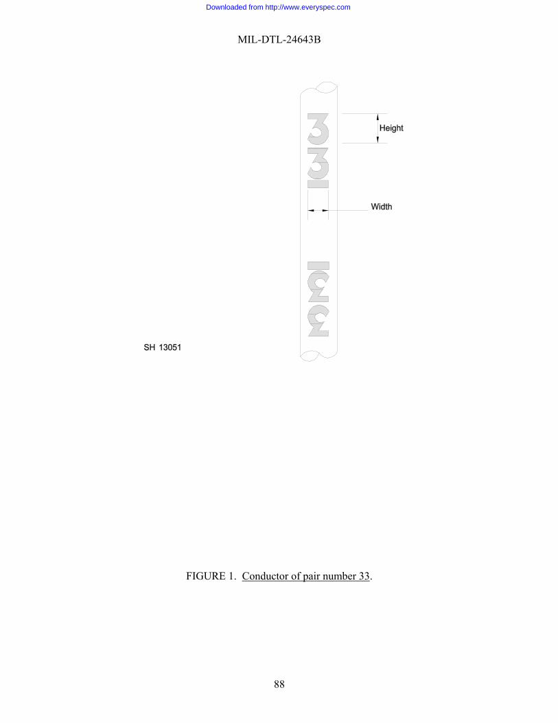
MIL-DTL-24643B
FIGURE 1. Conductor of pair number 33.
88
Downloaded from http://www.everyspec.com

MIL-DTL-24643B
ATTACHED TO ASSURE MOTORSHUT-OFF WHEN RELAYACTIVATES (AS BY PLACINGIN SERIES WITH MOTORELECTRICAL POWER SOURCE.)
NORMALLY CLOSELATCHING RELAY
ROTATINGMOTOR DRIVEN
CYLINDER
CYLINDER
FIXED SURFACE
SPEC
DIR OFROTATION 180° +/- 2
VSOURCE
12VMINIMUM
COUNTER
WEIGHT: 1 LB +/- .5 OZSPEC CNDCT
ABRADING ELEM(ONE OF TWO)
CLAMP OR OTHER MEANSTO ATTACH SPECIMENEND TO FIXED SURFACE
CLAMP TO HOLDABRADING ELEM(ONE OF FOUR)
TO ELECWIPER ONCYLINDER8 IN. +/- 1/8
SH 131362
FIGURE 2. Diagram of abrading machine for the abrasion resistance test.
CLCYLINDER SURFACE
ABRADINGELEMENT
0.3085 IN.MINIMUM
CENTERLINE TO BE TANGENTIAL WITHCYLINDER SURFACE +/- 0.003 INCHES
FIGURE 3. Detail diagram of abrading element fit on cylinder surface.
89
Downloaded from http://www.everyspec.com

MIL-DTL-24643B
V V
VOLTAGESTEP-UP
XFMR (IF NEEDED)
CURRENTXFMR
V
A
A
A
SPECIMEN
A
B
A
B
BUSBAR
INDUCTIVE-PICKUPTEST CURRENT METER
AUTOXFMR
3 PHASE60 HZ
VOLTAGESOURCE
60 HZ3 PHASE
VOLTAGESOURCE
AUTOXFMR
FUSE (OR OVERLOAD RELAY)
TEST VOLTAGE METER
GROUND ATTACHMENTFOR ARMORED CABLESONLY
FIGURE 4. Application of test voltage and test current for accelerated service test.
90
Downloaded from http://www.everyspec.com

MIL-DTL-24643B
FIGURE 5. Diagram of flexing machine for the bending endurance test.
91
Downloaded from http://www.everyspec.com

MIL-DTL-24643B
FIGURE 6. Diagram of bending apparatus for the cold working (minus 20oC) test.
FIGURE 7. Edge view of either sheave for the bending apparatus of the cold working (minus 20oC) test.
92
Downloaded from http://www.everyspec.com

MIL-DTL-24643B
AFLAME
LENGTH
MALE PIPE THREAD
B
D
C
Flame length plus 3/4"24"
For BurnerFlame
Lengths
2" 1-3/16" 1" 1"
B C D Thd ConnMale PipeA
PHYSICAL DIMENSIONS
FIGURE 8. Style X tubular brass manifold for gas flame test.
93
Downloaded from http://www.everyspec.com

MIL-DTL-24643B
Compressed air(oil-free and dry)
and valveAir regulator
Supply Side AWater Manometer
for Gas Pressure ControlGovernor Optional
Zero-PresssureModified
Natural orPropane Gas
Sources
Air-GasMixer
Air Inlet B
WaterManometer
H O2
H O H O
CABLE SPECIMEN
American Gas Furnace Co., N.J.Type 24 X Ribbon Gas Burner
1.75 in. min2.00 in. max
FIGURE 9. Schematic drawing of apparatus for gas flame test.
94
Downloaded from http://www.everyspec.com

MIL-DTL-24643B
FIGURE 10. Detail drawing of zero pressure governor modification.
V V
VOLTAGESTEP-UP
XFMR (IF NEEDED)
V
SPECIMEN
AUTOXFMR
FUSE (OR OVERLOAD RELAY)
TEST VOLTAGE METER
GROUND ATTACHMENTFOR ARMORED CABLESONLY
FIGURE 11. Application of test voltages for the gas flame test.
95
Downloaded from http://www.everyspec.com

MIL-DTL-24643B
1/2 POUND +/-1/64, -0 WEIGHT
BRAIDED COTTON TAPE
FIXED SUPPORT
AUTOMATIC COUNTER
ROTATING, MOTOT-DRIVEN DRUMWHICH REVERSES DIRECTION TOPRODUCE THE SPECIFIEDRECIPROCATE MOTION OF THE BRAIDED COTTON TAPE.
SPECIMEN
FIXED SUPPORT
RECIPROCATING TAPEMOTION OF 10" +1, -0
Figure 12. Diagram of typical abrading machine for the permanence of printing
(conductor insulation) test.
96
Downloaded from http://www.everyspec.com

MIL-DTL-24643B
SPECIMEN
PLUG (REMOVED PRIOR TOTEST)
MEASURED OVERALLSPECIMEN DIAMETERPLUS 1/2" MAXIMUM
HARDENED SEALANT
TERMINAL FITTING
APERTURE FOR INTRODUCING THEHARDENED SEALANT
TO SOURCE OFPRESSURIZED WATER
TO VALVE FORBLEED OFF AIR
6"MAXIMUM
SEALANT HEIGHT
1"MAXIMUM BETWEENSPECIMEN END FACE
AND SEALANT SURFACE
FIGURE 13. Diagram of terminal fitting, showing internal details, for the watertightness test.
97
Downloaded from http://www.everyspec.com

MIL-DTL-24643B
FIGURE 14. Acid gas test apparatus.
98
Downloaded from http://www.everyspec.com

MIL-DTL-24643B
FIGURE 15. Block diagram of electrical connections for the attenuation test when testing a single conductor plus surrounding shield.
SIGNALGENERATOR
CALIBRATEDVARIABLE
ATTENUATOR
FIXEDATTENUATOR
IMPEDANCE-MATCHING
TRANSFORMER(NOT REQUIRED)
DETECTOR
SINGLE CONDUCTOR PLUS SURROUNDINGSHIELD WITHIN SPECIMEN, ORAN ADAPTER CONNECTOR, OR ADIRECT CONNECTION, ASSPECIFIED (SEE 4.8.1.3)
IMPEDANCE-MATCHING
(NOT REQUIRED)TRANSFORMER ATTENUATOR
FIXED
99
Downloaded from http://www.everyspec.com

MIL-DTL-24643B
FIGURE 16. Block diagram of electrical connections for the attenuation test when testing a
conductor pair plus surrounding shield.
SIGNALGENERATOR
CALIBRATEDVARIABLE
ATTENUATOR
FIXEDATTENUATOR
IMPEDANCE-MATCHING
TRANSFORMER
CONDUCTOR PAIR PLUS SURROUNDINGSHIELD WITHIN SPECIMEN, ORAN ADAPTER CONNECTOR, OR ADIRECT CONNECTION, ASSPECIFIED (SEE 4.8.1.3)
TRANSFORMER
IMPEDANCE-MATCHING
FIXEDATTENUATOR
DETECTOR
100
Downloaded from http://www.everyspec.com

MIL-DTL-24643B
FIGURE 17. Block diagram of electrical connections for the pulse response test.
PULSEHEIGHT
90 PERCENT OFPULSE HEIGHT
10 PERCENT OFPULSE HEIGHT
RISE TIME FROM SIGNALCHANNEL NUMBER TWO
RISE TIME FROM SIGNALCHANNEL NUMBER ONE
LEADING EDGE OF PULSEFROM SIGNAL CHANNELNUMBER TWO
LEADING EDGE OF PULSEFROM SIGNAL CHANNELNUMBER ONE
PULSEGENERATOR
INPUTPULSE
TRANSFORMER
CONDUCTOR PAIR PLUS SURROUNDINGSHIELD WITHIN SPECIMEN
TRANSFORMER
OUTPUTPULSEOSCILLOSCOPE
SIGNALCHANNELNO. ONE
SIGNALCHANNELNO. TWO
FIGURE 18. Oscilloscope display showing rise time measurements for the pulse response time test.
101
Downloaded from http://www.everyspec.com

MIL-DTL-24643B
PULSEHEIGHT
90 PERCENT OFPULSE HEIGHT
10 PERCENT OFPULSE HEIGHT
DECAY TIME FROM SIGNALCHANNEL NUMBER TWO
DECAY TIME FROM SIGNALCHANNEL NUMBER ONE
TRAILING EDGE OF PULSEFROM SIGNAL CHANNELNUMBER ONE
TRAILING EDGE OF PULSEFROM SIGNAL CHANNELNUMBER TWO
FIGURE 19. Oscilloscope display showing decay time measurements for the pulse response time test.
Custodians: Preparing Activity: Army - MI Navy - SH Navy - SH (Project 6145-2308) Review Activities: Army - AR, AV, CR Navy - CG, EC DLA - IS
102
Downloaded from http://www.everyspec.com

STANDARDIZATION DOCUMENT IMPROVEMENT PROPOSAL INSTRUCTIONS
1. The preparing activity must complete blocks 1, 2, 3, and 8. In block 1, both the document number and revision letter should be given.
2. The submitter of this form must complete blocks 4,5,6, and 7. 3. The preparing activity must provide a reply within 30 days from receipt of this form. NOTE: This form may not be used to request copies of documents, nor to request waivers, or clarification of requirements on current contracts. Comments submitted on this form do not constitute or imply authorization to waive any portion of the referenced document(s) or to amend contractual requirements.
I RECOMMEND A CHANGE: 1. DOCUMENT NUMBER MIL-DTL-24643B
2. DOCUMENT DATE (YYMMDD) 22 August 2002
3. DOCUMENT TITLE CABLES AND CORDS, ELECTRIC, LOW SMOKE, FOR SHIPBOARD USE, GENERAL SPECIFICATION FOR4. NATURE OF CHANGE (Identify paragraph number and include proposed rewrite, if possible. Attach extra sheets as needed)
5. REASON FOR RECOMMENDATION
6. SUBMITTER a. NAME (Last, First, Middle Initial)
b. ORGANIZATION
c. ADDRESS (Include Zip Code)
d. TELEPHONE (Include Area Code) (1) Commercial (2) AUTOVON (if applicable)
7. DATE SUBMITTED (YYMMDD)
8. PREPARING ACTIVITY a. NAME Ruth Butler
b. TELEPHONE (Include Area Code) (1) Commercial (2) AUTOVON
202-781-3726 326-3726
c. ADDRESS (Include Zip Code) Commander, Naval Sea Systems Command ATTN: SEA 05Q 1333 Isaac Hull Avenue SE Stop 5160 Washington Navy Yard DC 20376-5160
IF YOU DO NOT RECEIVE A REPLY WITHIN 45 DAYS, CONTACT: Defense Quality and Standardization Office 5203 Leesburg Pike, Suite 1403, Falls Church, VA 22041-3466 Telephone (703) 756-2340 AUTOVON 289-2340
DD Form 1426, OCT 89 Previous editions are obsolete 198/290
Downloaded from http://www.everyspec.com