mil-dtl-38999 series i - benchmark connector 2 sales @aero-electric.com m i l – d t l – 3 8 9 9...
TRANSCRIPT

2www.conesys.com [email protected]
MIL–D
TL–
38999 S I
– –
MIL-DTL-38999Features and ApplicationSeries I
www.conesys.com [email protected]
Features and Application
MIL-DTL-38999 Series I is a bayonet coupling subminiature configuration with high contact density, ideal for smallerwire gauge, general-purpose applications. These environment-resisting connectors are 100% “scoop-proof.” Pins arerecessed in elongated shells to prevent the possibility ofbending contacts when plugs are scooped into the matingreceptacles.
This family of connectors is offered in 5 receptacle-mountingstyles. They include square flange receptacles, for both frontand rear panel (wall) mounting; square flange receptacles, forboth front and rear box mounting; and jam nut receptacleswhich incorporate “O” ring seals, designed for rear panel“D” hole mounting.
Standard plugs provide RFI protection by incorporating acontinuous strip of attached grounding fingers attenuatinginterference up to 1 GHz.
Fifty-seven insert arrangements per MIL-STD-1560 aretooled and qualified to MIL-DTL-38999 Series I, utilizing 2 to 128 contacts. Contacts come in sizes 22M, 22D, 20, 16,12, and 8 (coax and twinax), terminating wire sizes from 28gauge to 12 gauge including coaxial cable.
These connectors are available in wide range of shell materialsand finishes. Aluminum shells are offered in electroless nickel,olive drab cadmium and bright cadmium. Other finishessuch as anodic and zinc nickel are available upon request tocommercial callouts only. In addition, we offer passivatedstainless steel shells with standard environment-resistinginserts (commercial callouts only), and for highly corrosiveenvironments, nickel-aluminum-bronze shells with standardenvironment-resisting inserts (commercial callouts only).
Universal I/R Tool – A single, expendable plastic tool is usedfor both insertion and removal of contacts.
Scoop-Proof Design – Recessed pins in elongated shellsminimize the possibility for contact damage. In a blindmating application, mating shells cannot “scoop” the pins,and cause a shorting or bending of contacts.
Closed-Entry Socket Insert – Hard dielectric socket facehas lead-in chamfers for positive alignment of pins (evenpartially bent within pre-established limits) with sockets.
Interfacial Pin Insert Seal – Raised moisture barriersaround each pin, which mate into lead-in chamfers of hardface socket insert, provide individual contact sealing.Interfacial seal is never touched by service tools.
Elastomer Wire Sealing Grommet – Sealing over a widerange of wire diameters is assured by a triple wire seal ineach cavity at the rear of the connector.
Superior Contact Stability – Rear release crimp contactsystem features a stamped beryllium-copper retaining clipcaptivated by molded-in shoulders of each contact cavity inthe insulator. A rear-inserted M81969 plastic tool expandsthe tines beyond the shoulder, releasing the contact.
Shell Polarization – Alternate key/keyway positions preventcross mating of adjacent connectors having identical insertarrangement.
3www.conesys.com [email protected]
MIL–D
TL–
38999 S I
– –
MIL-DTL-38999Performance Specifications
Series I
www.conesys.com [email protected]
Performance SpecificationsOperating Temperature RangeFinish B: -65°C to +175°C (-85°F to +347°F)Finish F: -65°C to +200°C (-85°F to +392°FFinish A: -65°C to +150°C (-85°F to +302°F)
Material and Plating Data (Finish)B – aluminum shell, olive drab cadmium over nickel base F – aluminum shell, electroless nickel finishA– aluminum shell, silver to light iridescent yellow color(bright) cadmium over electroless nickel
Corrosion ResistanceFinishes A and B withstand 500-hour salt spray.Finish F withstands 48-hour salt spray.
DurabilityMinimum of 500 mating cycles
Environmental SealWired, mated connectors with specified accessoriesattached, shall meet the altitude-immersion test specified inMIL-DTL-38999.
Fluid ResistanceConnectors resist specified immersions in MIL-PRF-7808,MIL-PRF-23699, MIL-PRF-5606, M2-V Chevron oil, Coolanol25, MIL-DTL-83133 (JP-8), MIL-DTL-5624 (JP-4, JP-5),SAE-AMS1424 Type I, and other solvents and cleaning agents.
Shell-to-Shell Conductivity� Finish F = 1.0 millivolt maximum potential drop� Finishes A and B = 2.5 millivolts maximum potential drop
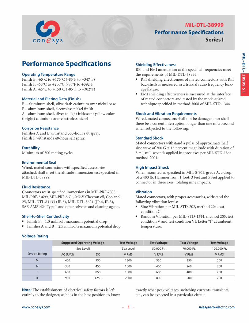
Voltage Rating
Shielding EffectivenessRFI and EMI attenuation at the specified frequencies meetthe requirements of MIL-DTL-38999.� RFI shielding effectiveness of mated connectors with RFI
backshells is measured in a triaxial radio frequency leak-age fixture.
� EMI shielding effectiveness is measured at the interfaceof mated connectors and tested by the mode-stirredtechnique specified in method 3008 of MIL-STD-1344.
Shock and Vibration RequirementsWired, mated connectors shall not be damaged, nor shallthere be a current interruption longer than one microsecondwhen subjected to the following:
Standard ShockMated connectors withstand a pulse of approximate halfsine wave of 300 G ± 15 percent magnitude with duration of3 ± 1 milliseconds applied in three axes per MIL-STD-1344,method 2004.
High Impact ShockWhen mounted as specified in MIL-S-901, grade A, a dropof a 400 lb. Hammer from 1 foot, 3 feet and 5 feet applied toconnector in three axes, totaling nine impacts.
VibrationMated connectors, with proper accessories, withstand thefollowing vibration levels:� Sine Vibration per MIL-STD-202, method 204, test
condition G. � Random Vibration per MIL-STD-1344, method 205, test
condition V and test condition VI, Letter “J” at ambienttemperature.
Service Rating
Suggested Operating Voltage Test Voltage Test Voltage Test Voltage Test Voltage
(Sea Level) Sea Level 50,000 Ft. 70,000 Ft. 100,000 Ft.
AC (RMS) DC V RMS V RMS V RMS V RMS
M 400 550 1300 550 350 200
N 300 450 1000 400 260 200
I 600 850 1800 600 400 200
II 900 1250 2300 800 500 200
Note: The establishment of electrical safety factors is leftentirely to the designer, as he is in the best position to know
exactly what peak voltages, switching currents, transients,etc., can be expected in a particular circuit.
4www.conesys.com [email protected]
MIL–D
TL–
38999 S I
MIL-DTL-38999Part Number DevelopmentSeries I
– –
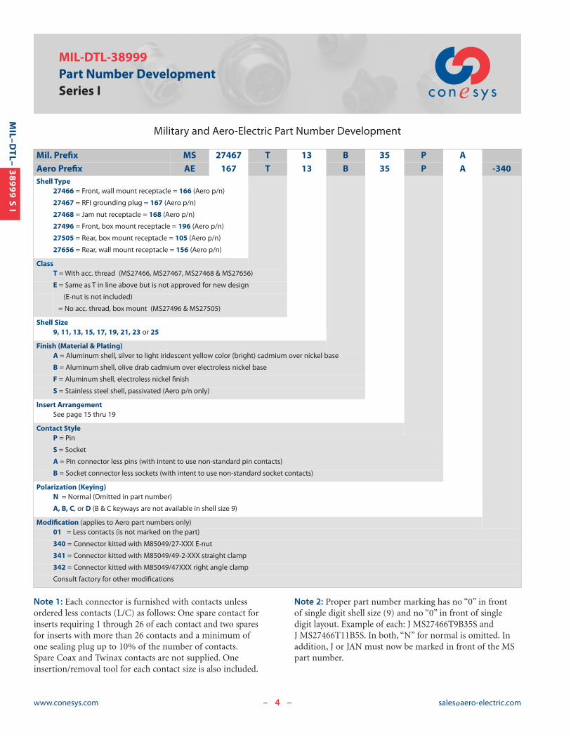
Military and Aero-Electric Part Number Development
Note 1: Each connector is furnished with contacts unlessordered less contacts (L/C) as follows: One spare contact forinserts requiring 1 through 26 of each contact and two sparesfor inserts with more than 26 contacts and a minimum ofone sealing plug up to 10% of the number of contacts.Spare Coax and Twinax contacts are not supplied. Oneinsertion/removal tool for each contact size is also included.
Note 2: Proper part number marking has no “0” in front of single digit shell size (9) and no “0” in front of singledigit layout. Example of each: J MS27466T9B35S andJ MS27466T11B5S. In both, “N” for normal is omitted. Inaddition, J or JAN must now be marked in front of the MSpart number.
Mil. Prefix MS 27467 T 13 B 35 P A
Aero Prefix AE 167 T 13 B 35 P A -340Shell Type
27466 = Front, wall mount receptacle = 166 (Aero p/n)
27467 = RFI grounding plug = 167 (Aero p/n)
27468 = Jam nut receptacle = 168 (Aero p/n)
27496 = Front, box mount receptacle = 196 (Aero p/n)
27505 = Rear, box mount receptacle = 105 (Aero p/n)
27656 = Rear, wall mount receptacle = 156 (Aero p/n)
ClassT = With acc. thread (MS27466, MS27467, MS27468 & MS27656)
E = Same as T in line above but is not approved for new design
(E-nut is not included)
= No acc. thread, box mount (MS27496 & MS27505)
Shell Size9, 11, 13, 15, 17, 19, 21, 23 or 25
Finish (Material & Plating)A = Aluminum shell, silver to light iridescent yellow color (bright) cadmium over nickel base
B = Aluminum shell, olive drab cadmium over electroless nickel base
F = Aluminum shell, electroless nickel finish
S = Stainless steel shell, passivated (Aero p/n only)
Insert ArrangementSee page 15 thru 19
Contact StyleP = Pin
S = Socket
A = Pin connector less pins (with intent to use non-standard pin contacts)
B = Socket connector less sockets (with intent to use non-standard socket contacts)
Polarization (Keying)N = Normal (Omitted in part number)
A, B, C, or D (B & C keyways are not available in shell size 9)
Modification (applies to Aero part numbers only)01 = Less contacts (is not marked on the part)
340 = Connector kitted with M85049/27-XXX E-nut
341 = Connector kitted with M85049/49-2-XXX straight clamp
342 = Connector kitted with M85049/47XXX right angle clamp
Consult factory for other modifications

5www.conesys.com [email protected]
MIL–D
TL–
38999 S I
MS27466Front, Wall Mounting Receptacle
AE166
Bayonet Coupling, Crimp Removable, Rear Release, Scoop-Proof
– –
[ HMAX
GROMMET
B
A
4x [ C
MASTER KEYWAY
[ E
BLUE COLOR BAND
J ACCESSORY TEETH
G ACCESSORY THREAD
1.323(33.60)MAX
D.219(5.56)
MIN. FULL THREAD
.060(1.52)MAX GROMMET EXTENSION
F
4X MINOR KEYWAYS
Page 4 Completed Part NumberPage 13 Contacts, Sealing Plugs and ToolsPages 17–19 Insert ArrangementsPage 3 Performance SpecificationsPages 15, 16 Insert Availability and Contact InformationPage 11 Polarization
ShellSize
A B � C D � E F G � H J
+.010 +.25 +.000 +.00 +.001 +.03 +.015 +.38 Accessory No. of±.020 ±.51 (TP) -.005 -.13 -.005 -.13 -.005 -.13 -.000 -.00 Thread Maximum Teeth
inch mm inch mm inch mm inch mm inch mm inch mm UNEF-2A inch mm
9 .938 23.83 .719 18.26 .128 3.25 .632 16.05 .572 14.53 .085 2.16 7/16-28 .299 7.59 12
11 1.031 26.19 .812 20.62 .128 3.25 .632 16.05 .700 17.78 .085 2.16 9/16-24 .427 10.85 16
13 1.125 28.58 .906 23.01 .128 3.25 .632 16.05 .850 21.59 .085 2.16 11/16-24 .541 13.74 20
15 1.219 30.96 .969 24.61 .128 3.25 .632 16.05 .975 24.77 .085 2.16 13/16-20 .666 16.92 24
17 1.312 33.32 1.062 26.97 .128 3.25 .632 16.05 1.100 27.94 .085 2.16 15/16-20 .791 20.09 28
19 1.438 36.53 1.156 29.36 .128 3.25 .632 16.05 1.207 30.66 .085 2.16 1-1/16-18 .897 22.78 32
21 1.562 39.67 1.250 31.75 .128 3.25 .602 15.29 1.332 33.83 .115 2.92 1-3/16-18 1.022 25.96 36
23 1.688 42.88 1.375 34.93 .147 3.73 .602 15.29 1.457 37.01 .115 2.92 1-5/16-18 1.147 29.13 40
25 1.812 46.02 1.500 38.10 .147 3.73 .602 15.29 1.582 40.18 .115 2.92 1-7/16-18 1.272 32.31 44

MIL–D
TL–
38999 S I
MS27656Rear, Wall Mounting ReceptacleAE156
Bayonet Coupling, Crimp Removable, Rear Release, Scoop-Proof
Page 4 Completed Part NumberPage 13 Contacts, Sealing Plugs and ToolsPages 17–19 Insert ArrangementsPage 3 Performance SpecificationsPages 15, 16 Insert Availability and Contact InformationPage 11 Polarization Note: See page 12 for panel thickness.
[ HMAX
GROMMET
J ACCESSORY TEETH
.219 (5.56)MIN FULL THREAD
.060 (1.52)MAX GROMMET EXTENSION
G ACCESSORY THREAD
B
A
4x [ C
MASTER KEYWAY
[ E
BLUE COLOR BAND
1.350 (34.29)MAX
D F
4X MINOR KEYWAYS
ShellSize
A B � C D � E F G � H J
+.010 +.25 +.000 +.00 +.001 +.03 +.015 +.38 Accessory No. of±.020 ±.51 (TP) -.005 -.13 -.005 -.13 -.005 -.13 -.000 -.00 Thread Maximum Teeth
inch mm inch mm inch mm inch mm inch mm inch mm UNEF-2A inch mm
9 .938 23.83 .719 18.26 .128 3.25 .820 20.83 .572 14.53 .085 2.16 7/16-28 .299 7.59 12
11 1.031 26.19 .812 20.62 .128 3.25 .820 20.83 .700 17.78 .085 2.16 9/16-24 .427 10.85 16
13 1.125 28.58 .906 23.01 .128 3.25 .820 20.83 .850 21.59 .085 2.16 11/16-24 .541 13.74 20
15 1.219 30.96 .969 24.61 .128 3.25 .820 20.83 .975 24.77 .085 2.16 13/16-20 .666 16.92 24
17 1.312 33.32 1.062 26.97 .128 3.25 .820 20.83 1.100 27.94 .085 2.16 15/16-20 .791 20.09 28
19 1.438 36.53 1.156 29.36 .128 3.25 .820 20.83 1.207 30.66 .085 2.16 1-1/16-18 .897 22.78 32
21 1.562 39.67 1.250 31.75 .128 3.25 .790 20.07 1.332 33.83 .115 2.92 1-3/16-18 1.022 25.96 36
23 1.688 42.88 1.375 34.93 .147 3.73 .790 20.07 1.457 37.01 .115 2.92 1-5/16-18 1.147 29.13 40
25 1.812 46.02 1.500 38.10 .147 3.73 .790 20.07 1.582 40.18 .115 2.92 1-7/16-18 1.272 32.31 44
www.conesys.com [email protected]– –
7www.conesys.com [email protected]
MIL–D
TL–
38999 S I
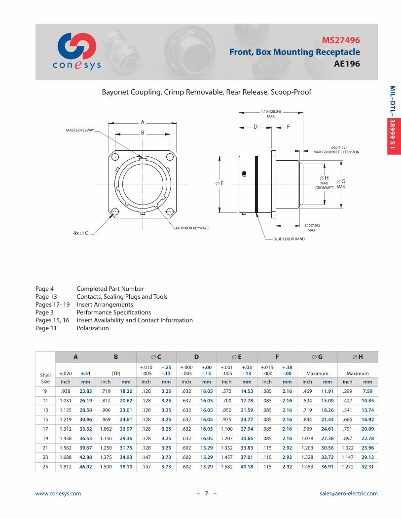
MS27496Front, Box Mounting Receptacle
AE196
Bayonet Coupling, Crimp Removable, Rear Release, Scoop-Proof
Page 4 Completed Part NumberPage 13 Contacts, Sealing Plugs and ToolsPages 17–19 Insert ArrangementsPage 3 Performance SpecificationsPages 15, 16 Insert Availability and Contact InformationPage 11 Polarization
[ HMAX
GROMMET[ GMAX
.312(7.93)MAX
.060(1.52)MAX GROMMET EXTENSION
B
A
4x [ C
MASTER KEYWAY
[ E
BLUE COLOR BAND
1.104(28.04)MAX
FD
4X MINOR KEYWAYS
– –
ShellSize
A B � C D � E F � G � H
+.010 +.25 +.000 +.00 +.001 +.03 +.015 +.38±.020 ±.51 (TP) -.005 -.13 -.005 -.13 -.005 -.13 -.000 -.00 Maximum Maximum
inch mm inch mm inch mm inch mm inch mm inch mm inch mm inch mm
9 .938 23.83 .719 18.26 .128 3.25 .632 16.05 .572 14.53 .085 2.16 .469 11.91 .299 7.59
11 1.031 26.19 .812 20.62 .128 3.25 .632 16.05 .700 17.78 .085 2.16 .594 15.09 .427 10.85
13 1.125 28.58 .906 23.01 .128 3.25 .632 16.05 .850 21.59 .085 2.16 .719 18.26 .541 13.74
15 1.219 30.96 .969 24.61 .128 3.25 .632 16.05 .975 24.77 .085 2.16 .844 21.44 .666 16.92
17 1.312 33.32 1.062 26.97 .128 3.25 .632 16.05 1.100 27.94 .085 2.16 .969 24.61 .791 20.09
19 1.438 36.53 1.156 29.36 .128 3.25 .632 16.05 1.207 30.66 .085 2.16 1.078 27.38 .897 22.78
21 1.562 39.67 1.250 31.75 .128 3.25 .602 15.29 1.332 33.83 .115 2.92 1.203 30.56 1.022 25.96
23 1.688 42.88 1.375 34.93 .147 3.73 .602 15.29 1.457 37.01 .115 2.92 1.328 33.73 1.147 29.13
25 1.812 46.02 1.500 38.10 .147 3.73 .602 15.29 1.582 40.18 .115 2.92 1.453 36.91 1.272 32.31

8www.conesys.com [email protected]
MIL–D
TL–
38999 S I
MS27505Rear, Box Mounting ReceptacleAE105
Bayonet Coupling, Crimp Removable, Rear Release, Scoop-Proof
– –
Page 4 Completed Part NumberPage 13 Contacts, Sealing Plugs and ToolsPages 17–19 Insert ArrangementsPage 3 Performance SpecificationsPages 15, 16 Insert Availability and Contact InformationPage 11 Polarization
[ HMAX
GROMMET
[ GMAX
.060(1.52)MAX GROMMET EXTENSION
B
A
4x [ C
MASTER KEYWAY
[ E
BLUE COLOR BAND
1.100(27.94)MAX
D F
4X MINOR KEYWAYS
ShellSize
A B � C D � E F � G � H
+.010 +.25 +.000 +.00 +.001 +.03 +.015 +.38±.020 ±.51 (TP) -.005 -.13 -.005 -.13 -.005 -.13 -.000 -.00 Maximum Maximum
inch mm inch mm inch mm inch mm inch mm inch mm inch mm inch mm
9 .938 23.83 .719 18.26 .128 3.25 .820 20.83 .572 14.53 .085 2.16 .547 13.89 .299 7.59
11 1.031 26.19 .812 20.62 .128 3.25 .820 20.83 .700 17.78 .085 2.16 .656 16.66 .427 10.85
13 1.125 28.58 .906 23.01 .128 3.25 .820 20.83 .850 21.59 .085 2.16 .828 21.03 .541 13.74
15 1.219 30.96 .969 24.61 .128 3.25 .820 20.83 .975 24.77 .085 2.16 .953 24.21 .666 16.92
17 1.312 33.32 1.062 26.97 .128 3.25 .820 20.83 1.100 27.94 .085 2.16 1.078 27.38 .791 20.09
19 1.438 36.53 1.156 29.36 .128 3.25 .820 20.83 1.207 30.66 .085 2.16 1.203 30.56 .897 22.78
21 1.562 39.67 1.250 31.75 .128 3.25 .790 20.07 1.332 33.83 .115 2.92 1.328 33.73 1.022 25.96
23 1.688 42.88 1.375 34.93 .147 3.73 .790 20.07 1.457 37.01 .115 2.92 1.453 36.91 1.147 29.13
25 1.812 46.02 1.500 38.10 .147 3.73 .790 20.07 1.582 40.18 .115 2.92 1.578 40.08 1.272 32.31
Note: See page 12 for panel thickness.

9www.conesys.com [email protected]
MIL–D
TL–
38999 S I
MS27468Jam Nut Receptacle
AE168
Bayonet Coupling, Crimp Removable, Rear Release, Scoop-Proof
– –
Page 4 Completed Part NumberPage 13 Contacts, Sealing Plugs and ToolsPages 17–19 Insert ArrangementsPage 3 Performance SpecificationsPages 15, 16 Insert Availability and Contact InformationPage 11 Polarization
PANEL THICKNESS.125(3.18).062(1.57)
[ D
3X BAYONET PINSEQUALLY SPACED
MASTER KEYWAY
E
BLUE COLOR BAND4X MINOR KEYWAYS
"O"-RING
KFLAT
[ A
HEX NUTPER MS3186
J THREAD
1.308 (33.22)MAX
.615 (15.62)
.598 (15.19)
.920 (23.37)
.910 (23.11)
BLUE COLOR BAND
G No. OF TEETH
F ACCESSORY THREAD
[ C MAX
GROMMET
.060 (1.52) MAXGROMMET EXTENSION
B
ShellSize
� A B � C � D E F G J K
+.001 +.03 +.011 +.28 Accessory No. of Jam Nut Thread Flat-.005 -.13 -.010 -.25 Maximum ±.016 ±.41 ±.016 ±.41 Thread Teeth Class 2A ±.005 ±.13
inch mm inch mm inch mm inch mm inch mm UNEF- 2A inch mm
9 .572 14.53 .109 2.77 .299 7.59 1.188 30.18 1.062 26.97 7/16-28 12 11/16-24UNEF .650 16.51
11 .700 17.78 .109 2.77 .427 10.85 1.375 34.93 1.250 31.75 9/16-24 16 13/16-20UNEF .750 19.05
13 .850 21.59 .109 2.77 .541 13.74 1.500 38.10 1.375 34.93 11/16-24 20 1-20UNEF .937 23.80
15 .975 24.77 .109 2.77 .666 16.92 1.625 41.28 1.500 38.10 13/16-20 24 1-1/8-18UNEF 1.061 26.95
17 1.100 27.94 .109 2.77 .791 20.09 1.750 44.45 1.625 41.28 15/16-20 28 1-1/4-18UNEF 1.186 30.12
19 1.207 30.66 .140 3.56 .897 22.78 1.938 49.23 1.812 46.02 1-1/16-18 32 1-3/8-18UNEF 1.311 33.30
21 1.332 33.83 .140 3.56 1.022 25.96 2.062 52.37 1.938 49.23 1-3/16-18 36 1-1/2-18UNEF 1.436 36.47
23 1.457 37.01 .140 3.56 1.147 29.13 2.188 55.58 2.062 52.37 1-5/16-18 40 1-5/8-18UNEF 1.561 39.65
25 1.582 40.18 .140 3.56 1.272 32.31 2.312 58.72 2.188 55.58 1-7/16-18 44 1-3/4-18UNS 1.686 42.82
10www.conesys.com [email protected]
MIL–D
TL–
38999 S I
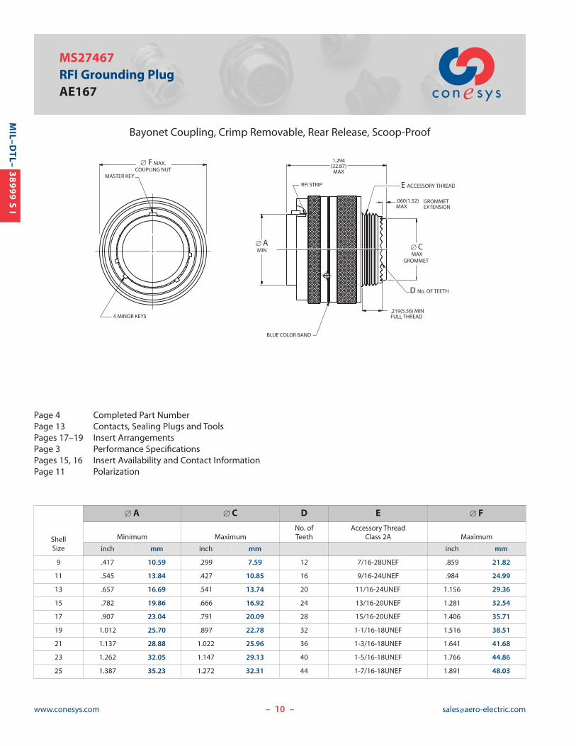
MS27467RFI Grounding PlugAE167
Bayonet Coupling, Crimp Removable, Rear Release, Scoop-Proof
– –
Page 4 Completed Part NumberPage 13 Contacts, Sealing Plugs and ToolsPages 17–19 Insert ArrangementsPage 3 Performance SpecificationsPages 15, 16 Insert Availability and Contact InformationPage 11 Polarization
GROMMET EXTENSION
D No. OF TEETH
[ AMIN [ C
MAXGROMMET
[ F MAX.COUPLING NUT
E ACCESSORY THREAD
.219(5.56) MINFULL THREAD
BLUE COLOR BAND
4 MINOR KEYS
MASTER KEY
RFI STRIP
1.294(32.87)
MAX
.060(1.52)MAX
ShellSize
� A � C D E � F
No. of Accessory ThreadMinimum Maximum Teeth Class 2A Maximum
inch mm inch mm inch mm
9 .417 10.59 .299 7.59 12 7/16-28UNEF .859 21.82
11 .545 13.84 .427 10.85 16 9/16-24UNEF .984 24.99
13 .657 16.69 .541 13.74 20 11/16-24UNEF 1.156 29.36
15 .782 19.86 .666 16.92 24 13/16-20UNEF 1.281 32.54
17 .907 23.04 .791 20.09 28 15/16-20UNEF 1.406 35.71
19 1.012 25.70 .897 22.78 32 1-1/16-18UNEF 1.516 38.51
21 1.137 28.88 1.022 25.96 36 1-3/16-18UNEF 1.641 41.68
23 1.262 32.05 1.147 29.13 40 1-5/16-18UNEF 1.766 44.86
25 1.387 35.23 1.272 32.31 44 1-7/16-18UNEF 1.891 48.03

11www.conesys.com [email protected]
MIL–D
TL–
38999 S I
MIL-DTL-38999Polarization
Series I
– –
Keying Positions
Notes:1. Mating face of receptacle shown (plug is opposite).2. The master keyway (key) has various positions relative to
DATUM F; the minor keyways (keys) remain fixed asshown. In the Normal position, the master keyway (key)is at 95° from DATUM F.
3. The angles for a given connector are the same whether itcontains pin or socket inserts.
4. The insert arrangement does not rotate relative to masterkeyway (key).
DATUM F
D°
N°A°
C°
B°
MASTERKEYWAY
NORMAL
5°
ShellSize
Keying Positions
BSC
N° A° B° C° D°9 95 77 – – 113
11 95 81 67 123 109
13 95 75 63 127 115
15 95 74 61 129 116
17 95 77 65 125 113
19 95 77 65 125 113
21 95 77 65 125 113
23 95 80 69 121 110
25 95 80 69 121 110

12www.conesys.com [email protected]
MIL–D
TL–
38999 S I
MIL-DTL-38999 Series IFlange and Jam Nut ReceptaclesPanel Cutouts
Panel Cutouts
– –
Flange and Jam Nut Mounting Dimensions
ShellSize
A � B � C D E � F
+.000 +.00 +.010 +.25(TP) Minimum ±.005 ±.13 Maximum -.010 -.25 -.000 -.00
inch mm inch mm inch mm inch mm inch mm inch mm
9 .719 18.26 .656 16.66 .128 3.25 .234 5.94 .670 17.02 .700 17.78
11 .812 20.62 .796 20.22 .128 3.25 .234 5.94 .771 19.59 .825 20.96
13 .906 23.01 .922 23.42 .128 3.25 .234 5.94 .955 24.26 1.010 25.65
15 .969 24.61 1.047 26.59 .128 3.25 .234 5.94 1.085 27.56 1.135 28.83
17 1.062 26.97 1.219 30.96 .128 3.25 .234 5.94 1.210 30.73 1.260 32.01
19 1.156 29.36 1.297 32.94 .128 3.25 .234 5.94 1.335 33.91 1.385 35.18
21 1.250 31.75 1.422 36.12 .128 3.25 .204 5.18 1.460 37.08 1.510 38.35
23 1.375 34.93 1.547 39.29 .154 3.91 .204 5.18 1.585 40.26 1.635 41.53
25 1.500 38.10 1.672 42.47 .154 3.91 .193 4.90 1.710 43.43 1.760 44.70
A[ F
4x [ C
FLANGE MOUNT
[ BMIN
D MAXPANEL THICKNESS
.125(3.18)
.062(1.57)PANEL THICKNESS
JAM NUT
E
Note 1: Flange Mounting Dimensions (� B cutout and D MAX) listed only for back of panel mounting (MS27505and MS27656).
Note 2: D MAX includes mounting hardware.
13www.conesys.com [email protected]
MIL–D
TL–
38999 S I
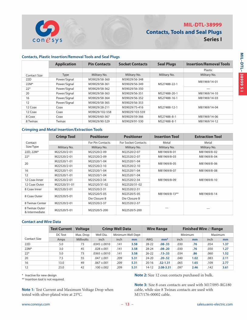
MIL-DTL-38999Contacts, Tools and Seal Plugs
Series I
Contacts, Plastic Insertion/Removal Tools and Seal Plugs
Crimping and Metal Insertion/Extraction Tools
Contact and Wire Data
– –
Contact Size
Application Pin Contacts Socket Contacts Seal Plugs Insertion/Removal ToolsPlastic
Type Military No. Military No. Military No. Military No.
22D Power/Signal M39029/58-360 M39029/56-348
MS27488-22-1M81969/14-01
22M* Power/Signal M39029/58-361 M39029/56-349
22* Power/Signal M39029/58-362 M39029/56-350 —
20 Power/Signal M39029/58-363 M39029/56-351 MS27488-20-1 M81969/14-10
16 Power/Signal M39029/58-364 M39029/56-352 MS27488-16-1 M81969/14-03
12 Power/Signal M39029/58-365 M39029/56-353
MS27488-12-1 M81969/14-0412 Coax Coax M39029/28-211 M39029/75-416
12 Coax Coax M39029/102-558 M39029/103-559
8 Coax Coax M39029/60-367 M39029/59-366 MS27488-8-1 M81969/14-06
8 Twinax Twinax M39029/90-529 M39029/91-530 MS27488-8-1 M81969/14-12
ContactSize/Type
Crimp Tool Positioner Positioner Insertion Tool Extraction ToolFor Pin Contacts For Socket Contacts Metal Metal
Military No. Military No. Military No. Military No. Military No.
22D, 22M* M22520/2-01 M22520/2-09 M22520/2-07 M81969/8-01 M81969/8-02
22* M22520/2-01 M22520/2-09 M22520/2-07 M81969/8-03 M81969/8-04
20M22520/1-01 M22520/1-04 M22520/1-04
M81969/8-05 M81969/8-06M22520/2-01 M22520/2-10 M22520/2-10
16 M22520/1-01 M22520/1-04 M22520/1-04 M81969/8-07 M81969/8-08
12 M22520/1-01 M22520/1-04 M22520/1-04
M81969/8-09 M81969/8-1012 Coax Inner M22520/2-01 M22520/2-34 M22520/2-34
12 Coax Outer M22520/31-01 M22520/31-02 M22520/31-02
8 Coax Inner M22520/2-01 M22520/2-31 M22520/2-31
M81969/8-13** M81969/8-148 Coax Outer M22520/5-01
M22520/5-05 M22520/5-05
Die Closure B Die Closure B
8 Twinax Center M22520/2-01 M22520/2-37 M22520/2-37
— —8 Twinax Outer & Intermediate
M22520/5-01 M22520/5-200 M22520/5-200
Contact Size
Test Current Voltage Crimp Well Data Wire Range Finished Wire � RangeDC Test Max. Drop Well Dia. Minimum Well Dept Minimum Maximum
Amps Millivolts inch inch mm AWG mm2 inch mm inch mm
22D 5.0 73 .0345 ±.0010 .141 3.58 28-22 .08-.33 .030 .76 .054 1.37
22M* 3.0 45 .028 ±.001 .141 3.58 28-24 .08-.20 .030 .76 .050 1.27
22* 5.0 73 .0365 ±.0010 .141 3.58 26-22 .13-.33 .034 .86 .060 1.52
20 7.5 55 .047 ±.001 .209 5.31 24-20 .20-.52 .040 1.02 .083 2.11
16 13.0 49 .067 ±.001 .209 5.31 20-16 .52-1.31 .065 1.65 .109 2.77
12 23.0 42 .100 ±.002 .209 5.31 14-12 2.08-3.31 .097 2.46 .142 3.61
* Inactive for new design** Insertion tool is not required.
Note 1: Test Current and Maximum Voltage Drop whentested with silver-plated wire at 25°C.
Note 2: Size 12 coax contacts purchased in bulk.
Note 3: Size 8 coax contacts are used with M17/095-RG180cable, while size 8 Twinax contacts are used with M17/176-00002 cable.

14www.conesys.com [email protected]
MIL–D
TL–
38999 S I
MIL-DTL-38999Contact Installation InstructionsSeries I
– –
Contact InstallationInstructions
Crimping Contacts 1. Select the appropriate crimp tool and ensure that the
proper crimp head positioner is used.
2. Cycle the tool to be sure the indentors are open.
3. Determine the correct selector setting for the wire sizefrom the data plate on the positioner (turret head assembly) and set the selector knob on the crimp tool to match.
4. Place the contact, mating end first, into the tool.
5. Insert the stripped wire into the hollow end of the contact. Be sure the wire is inserted as far as it will go.
6. Close the tool completely to crimp. Unless the tool isclosed completely, the tool will not release the contact.
7. Remove the crimped contact from the tool. Check theinspection hole to verify that the wire is fully inserted.
Insertion of Contacts1. Before inserting the contacts, unscrew the accessories
(clamps, backshells or adapters) from rear of plug orrecep tacle. Slide the hardware over the wire bundle in the proper order for reassembly after all the contacts are inserted.
2. To assist insertion of contacts, lubricate insulator (grommet) cavities with isopropyl alcohol. Alcohol willevaporate and will not leave a conductive film. Caution:Never use any lubricant other than isopropyl alcohol.
3. Place the correct insertion tool on the contact so that thewire runs along the groove in the tool. (Tool tip will buttagainst the shoulder.) Hold the plug or receptacle bodyfirmly.
4. Beginning with a center cavity, insert the contact into theinsulator with a slow, even pressure until the contactsnaps into position. Make sure the contact and tool areheld perpendicular to the face of the insert during thecontact installation or the grommet could be damaged.
4.1 If contacts are not inserted all the way prior toremoving insertion tool, do not try to reinsert theinsertion tool. Instead, remove the contact and tryagain; otherwise reinserting the insertion tool maydamage the inside of the contact cavity.
5. Remove tool and check the face of the connector forproper contact installation. Proper installation may alsobe checked by pulling back lightly on the wire to makesure the contact is properly seated.
CompletionAfter all the cavities have been filled, slide the hardware backinto position on the connector and tighten.
Extraction of Contacts (Rework)1. Slide the hardware back over the wire bundle.
2. Select the appropriate tool. Place the wire into theextraction tool of the pin or socket.
3. Slowly slide the extraction tool down wire into the contact cavities until the tool tip bottoms against thecontact shoulder, expanding the clip retaining tines. Holdthe wire firmly in the tool and pull the wired contact andtool straight out of the rear of the insulator.
Size Pin Contact Socket Contact Basic Crimp Tool Pin Positioner Socket Positioner Insertion/Removal Tool
22D M39029/58-360 M39029/56-348 M22520/2-01 M22520/2-09 M22520/2-07 M81969/14-01
22M M39029/58-361 M39029/56-349 M22520/2-01 M22520/2-09 M22520/2-07 M81969/14-01
22 M39029/58-362 M39029/56-350 M22520/2-01 M22520/2-09 M22520/2-07 M81969/14-01
20 M39029/58-363 M39029/56-351M22520/1-01 M22520/1-04 Red M22520/1-04 Red
M81969/14-10M22520/2-01 M22520/2-10 M22520/2-10
16 M39029/58-364 M39029/56-352 M22520/1-01 M22520/1-04 Blue M22520/1-04 Blue M81969/14-03
12 M39029/58-365 M39029/56-353 M22520/1-01 M22520/1-04 Yellow M22520/1-04 Yellow M81969/14-04
For coax and twinax contacts refer to instructions that are supplied with contacts.

Please see next page for Shell Sizes 21/20/G thru25/24/J layouts.
15www.conesys.com [email protected]
MIL–D
TL–
38999 S I
MIL-DTL-38999 Series I, II and IIIInsert Availability and Contact Information
per MIL-STD-1560
Insert Availability and Contact Information
– –
Insert Arrangement
Aero-Electric Service Total Quantity of ContactsStatus No. of (by Size)
Series I Series II Series III QPL’d Tooled Rating Contacts 22D 22M 22 20 16 12 10 8
9-6* 8-6* — Yes Yes M 6 6
9-35 8-35 A35 Yes Yes M 6 6
9-98 8-98 A98 Yes Yes I 3 3
11-2 — B2 Yes Yes I 2 2
11-4 — B4 Yes Yes I 4 4
11-5 10-5 B5 Yes Yes I 5 5
11-13* 10-13* — Yes Yes M 13 13
11-35 10-35 B35 Yes Yes M 13 13
11-98 10-98 B98 Yes Yes I 6 6
11-99 10-99 B99 Yes Yes I 7 7
— 12-3 — Yes Yes II 3 3
13-4 12-4 C4 Yes Yes I 4 4
13-8 12-8 C8 Yes Yes I 8 8
13-22* 12-22* — Yes Yes M 22 22
13-35 12-35 C35 Yes Yes M 22 22
13-98 12-98 C98 Yes Yes I 10 10
15-5 14-5 D5 Yes Yes II 5 5
15-15 14-15 D15 Yes Yes I 15 14 1
15-18 14-18 D18 Yes Yes I 18 18
15-19 — D19 Yes Yes I 19 19
15-35 14-35 D35 Yes Yes M 37 37
15-37* 14-37* — Yes Yes M 37 37
15-97 14-97 D97 Yes Yes I 12 8 4
17-6 16-6 E6 Yes Yes I 6 6
17-8 16-8 E8 Yes Yes II 8 8
17-26 16-26 E26 Yes Yes I 26 26
17-35 16-35 E35 Yes Yes M 55 55
17-55* 16-55* — Yes Yes M 55 55
17-99 16-99 E99 Yes Yes I 23 21 2
19-11 18-11 F11 Yes Yes II 11 11
19-28 18-28 F28 Yes Yes I 28 26 2
19-30 18-30 F30 Yes Yes I 30 29 1
19-32 18-32 F32 Yes Yes I 32 32
19-35 18-35 F35 Yes Yes M 66 66
— 18-53** — Yes Yes M 53 53
19-66* 18-66* — Yes Yes M 66 66
* Not approved for new design. Tooled and qualified but their separatepictorials are not shown on pages 17 thru 19, as they are the same ascorresponding (-35) layouts that take same qty of 22D instead of 22Mcontacts.
** Not approved for new design. Pictorial is shown on page 18.
— above means “not available” for that series.
38999 S II
38999 S III

16www.conesys.com [email protected]
MIL–D
TL–
38999 S I
MIL-DTL-38999 Series I, II and IIIInsert Availability and Contact Informationper MIL-STD-1560
Insert Availability and Contact Information (continued)
– –
Insert Arrangement
Aero-Electric Service Total Quantity of Contacts
Status No. of (by Size)
Series I Series II Series III QPL’d Tooled Rating Contacts 22D 22M 22 20 16 12 10 8
21-1* 20-1* — Yes Yes M 79 79
21-11 — G11 Yes Yes I 11 11
21-16 20-16 G16 Yes Yes II 16 16
21-35 20-35 G35 Yes Yes M 79 79
21-39 20-39 G39 Yes Yes I 39 37 2
21-41 20-41 G41 Yes Yes I 41 41
21-48** — G48** N/A Yes I 4 4 (Power)
21-75 — G75 Yes Yes Twinax 4 4 (Twinax)
23-1* 22-1* — Yes Yes M 100 100
23-2*** 22-2*** — Yes Yes M 85 85
23-21 22-21 H21 Yes Yes II 21 21
23-32 22-32 H32 Yes Yes I 32 32
23-35 22-35 H35 Yes Yes M 100 100
23-53 22-53 H53 Yes Yes I 53 53
23-55 22-55 H55 Yes Yes I 55 55
25-1* 24-1* — Yes Yes M 128 128
25-4 24-4 J4 Yes Yes I 56 48 8
— — J8 Yes Yes Twinax 8 8 (Twinax)
— — J11 Yes Yes N 11 2 9
25-19 24-19 J19 Yes Yes I 19 19
— — J20 Yes Yes N, Coax, Twinax 30 10 13 4 (Coax) 3 (Twinax)
25-24 24-24 J24 Yes Yes I 24 12 12
25-29 24-29 J29 Yes Yes I 29 29
25-35 24-35 J35 Yes Yes M 128 128
25-43 — J43 Yes Yes I 43 23 20
25-46 — J46**** Yes Yes I, Coax 46 40 4 2 (Coax)
25-61 24-61 J61 Yes Yes I 61 61
— — J90 Yes Yes I, Twinax 46 40 4 2 (Twinax)
* Not approved for new design. Tooled and qualified but their separatepictorials are not shown on pages 17 thru 19, as they are same as corresponding (-35) layouts that take same quantity of 22D instead of 22M contacts.
** 21-48/G48 layout is not to MIL-STD-1560. It is tooled and intended forcomm’l use only.
*** Not approved for new design. Pictorial is shown on page 18.
**** J46 in Series III is not QPL’d but can be purchased to comm’l number(Size 8 Coax contact must be used).
— above means “not available” for that series
Note 1: J20P uses 4 size 12 coax contacts as follows: 2 ea M39029/28-211 and 2 ea of M39029/102-558; J20S uses 4 size 12 coax contacts as follows: 2 ea M39029/75-416 and 2 ea of M39029/103-559.
Note 2: Layouts (G75, J8, J20, J46 and J90) that take twinaxor coax contacts should not be used for firewall applications(Classes K & S) in Series III.
Note 3: H and J contact styles (in lieu of P & S) are meantfor Composite (classes J & M) Series III only. Aluminum(classes A, B, F & W) and Firewall (classes K & S) are ratedfor 500 cycles regardleess what contacts are used.
38999 S II
38999 S III

17www.conesys.com [email protected]
MIL–D
TL–
38999 S I
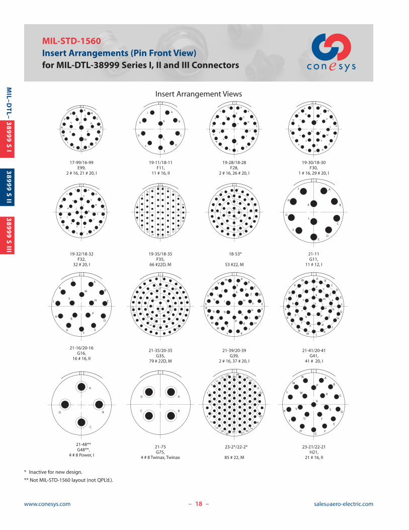
MIL-STD-1560Insert Arrangements (Pin Front View)
for MIL-DTL-38999 Series I, II and III Connectors
Insert Arrangement Views
– –
1
23
4
56
9-35/8-35A35,
6 # 22D, M
A
B
C
9-98/8-98A98,
3 # 20, I
AB
11-2B2,
2 # 16, I
A
BC
D
11-4B4,
4 # 20, I
A
BC
D
E
11-5/10-5B5,
5 # 20, I
12
3
45
67
8
9
10 11
1213
11-35/10-35B35,
13 # 22D, M
A
B
CD
E F
11-98/10-98B98,
6 # 20, I
A
B
CD
E
FG
11-99/10-99B99,
7 # 20, I
A
B
C
12-3
3 # 16, II
A
B
C
D
13-4/12-4C4,
4 # 16, I
A
B
CD
E
F
G
H
13-8/12-8C8,
8 # 20, I
13-35/12-35C35,
22 # 22D, M
AB
C
D
E
F
G
H
JK
13-98/12-98C98,
10 # 20, I
A
B
CD
E
15-5/14-5D5,
5 # 16, II
A
B
C
D
E
F
G
H
J
K
L
MR N
15-15/14-15D15,
1 # 16, 14 # 20, I
A
B
C
D
EFG
H
J
K
L
M N
P
RS
T U
15-18/14-18D18,
18 # 20, I
A B
C
D
E
FG
H
J
K
L
M
N P
R
ST
U V
15-19D19,
19 # 20, I
15-35/14-35D35,
37 # 22D, M
A
B
C
D
EF
G
H
J
K
L
M
15-97/14-97D97,
4 # 16, 8 # 20, I
A
B
C
D
E
F
17-6/16-6E6,
6 # 12, I
A
B
C
DE
F
G
H
17-8/16-8E8,
8 # 16, II
AB
C
D
E
F
G
HJK
LM
N
P
RS T
U
V
WX
Y
Z
a b
c
17-26/16-26E26,
26 # 20, I
17-35/16-35E35,
55 # 22D, M
P
1
3
4
9
10
16
17
24
25
31
32
39
40
46
47
52
53
55
1
15
22
21
14
21
1
31
38999 S II
38999 S III
18www.conesys.com [email protected]
MIL–D
TL–
38999 S I
MIL-STD-1560Insert Arrangements (Pin Front View)for MIL-DTL-38999 Series I, II and III Connectors
Insert Arrangement Views
– –
17-99/16-99E99,
2 # 16, 21 # 20, I
19-11/18-11F11,
11 # 16, II
19-35/18-35F35,
66 #22D, M
18-53*
53 #22, M
21-11G11,
11 # 12, I
21-16/20-16G16,
16 # 16, II
21-75G75,
4 # 8 Twinax, Twinax
A
B
C
D
E
L
F
G
H
J
K
AB
C
D
E
FG
HJK
L
M
N
P
RS T
U
V
W
X
Y Z
19-28/18-28F28,
2 # 16, 26 # 20, I
A
B
C
D
E
F
G
JKL
M
N
P
R
S
T
U
V
W
X
Y
Z
a
b
c
d
e
19-30/18-30F30,
1 # 16, 29 # 20, I
A
B
C
D
E
F
GH
J
K
L
M
N
P
RS
T
U
V
W
X
Y
Z
a
b
c
d
e
fg
1
3
4
9
10
16
17
24
25
33
34
42
43
50
51
57
58
63
64
66
19-32/18-32F32,
32 # 20, I
A
B
C
D
E
F
GJ
HKL
M
N
P
R
S
T
U
V
W
X
Y
Zab
c
d
e
f
g
h
j
A
B
C
DE
F
G
H
J
K
L
A
B
C
D
EF
G
H
J
K
L
M
N
P
R
S
21-41/20-41G41,
41 # 20, I
21-48**G48**,
4 # 8 Power, I
AB
CD
E
F
G
H
J
KLM
N
P
R
S
T
U
V
W
XY
Z
a
b
c
def
g
h
i
j
km
tn
pq
r
s
21-39/20-39G39,
2 # 16, 37 # 20, I
AB
C
D
E
F
G
H
JKL
M
N
P
RS
T
U
VX
YZ
W
a
b
c
de
f
g
h
ij
k
m
n
p
q
r
A
BC
D
A
B
C
D
23-21/22-21H21,
21 # 16, II
23-2*/22-2*
85 # 22, M
A
B
C
D
E
FG
H
J
K
L
M
N
P
R
S
TU
V
W
X
21-35/20-35G35,
79 # 22D, M
1
11
7121
31
41
51
61
79
1
11
21
31
52
51
53
1
4
5
11
12
19
20
28
29
38
39
47
48
57
58
66
67
74
75
81
82
85
* Inactive for new design.
** Not MIL-STD-1560 layout (not QPL’d.).
38999 S II
38999 S III

19www.conesys.com [email protected]
MIL–D
TL–
38999 S I
MIL-STD-1560Insert Arrangements (Pin Front View)
for MIL-DTL-38999 Series I, II and III Connectors
Insert Arrangement Views
– –
J88 # 8 Twinax,
Twinax
J119 # 10, 2 # 20,
N
25-24/24-24J24,
12 # 12, 12 # 16, I
23-53/22-53H53,
53 # 20, I
23-35/22-35H35,
100 # 22D, M
AB
C
D
E
F
G
HJ
K
L
M
N
P
RS
T
UV
W
X
Y
Za
bc
d
ef
g
h
km
n
pq
r
s
tu
vw
x
y
z
AABB
CC
DDEE
FF
GGHH
23-55/22-55H55,
55 # 20, I
a
bc
de
fg
H
i
j
km
np
qr
s
t
uv
wx
y
z
AB
C
D
E
F
G
HJK
L
M
N
P
R
S
TU
VW
XY
Z
AA
BB
CC
DDEEFF
GGHH
25-4/24-4J4,
8 # 16, 48 # 20, I
e
AB
CD
E
F
G
H
J
KL
MN
X
YZ
a
bc
d
f
g
h
k
mnP
R
S
T
U
V
W
p
q
r
s
t
uv
w
x
y
z
AA
BBCC
DD
EE
FF
GG
HH
JJ
KKLL
25-19/24-19J19,
19 # 12, I
A B
C
D
E
FGH
J
K
L
M
N P
R
ST
U V
25-43J43,
20 # 16, 23 # 20, I
AB
C
D
E
F
G
H
J
KLM
N
P
R
S
T
U
V
W
XY
Z
a
b
c
d
efg
h
k
m
n p
r
stu
v
w
x
q
25-29/24-29J29,
29# 16, I
AB
C
D
E
F
GHJ
K
L
M
N
P
RS T
U
V
W
XY
Z
a
b c
d
e
f
a
AB
C
D
E
F
GHJ
K
L
M
N
P
R
S
T
UV
W
X
Y
Z
25-46J46,
40 # 20, 4 # 16, 2 # 8 Coax, I / Coax
AB
C
D
E
F
G
H
JKL
M
N
P
R
S
T
U
VW
XY
Za
b
cd
efg
h
k
m
n
p
r
s
t u
v
w
xy
z
AA
q
25-61/24-61J61,
61 # 20, I
A
B
C
D
E
F
G
H
JK
LMN
P
R
S
T
U
V
W
X
YZa b
cd
e
f
g
h
jkm
n
P
r
s
t
uv
w
x
y
z
AABB
CC
DD
EE
FF
GGHH
JJ
KKLL
MM
NNPP
i
q
J90,40 # 20, 4 # 16, 2 # 8 Twinax,
I / Twinax
A
B
C
DE
F
GH
A
B
C
D
EF
G
H
L
J
K
J2010 # 20,13 # 16, 4 # 12, 3 # 8 Twinax,
N / Coax / Twinax
AB
C
D
E
F
G
H
JKL
M
N
P
R
S
T
U
VW
XY
Za
b
cd
efg
h
k
m
n
p
r
s
t u
v
w
xy
z
AA
q
AB
C
D
E
F
G
H
J
K
L
M
N
P
R
S
T
U
VWX
Y
Z
1
23
4
5
67
1
2
3
5
6
8
715
16
24
25
34
35
45
46
55
4
56
66
67
76
77
85
86
93
94
95
9697
98
99
10 0
25-35/24-35J35,
128 # 22D, M
1
4
7
8
14
15
24
25
35
36
47
48
58
59
70
71
81
8294
105
115
122
125
12111 4
10493
23-32/22-32H32,
32 # 20, I
A
B
C
D
E
FG
H
J
K
L
M
N
PR
S
T
U
V
W
X
Y
Z
a
b
c
d
ef
g
h
i
38999 S II
38999 S III