mil-hdbk-231a superseding mil-hdbk-231(as) 1 july 1970...
TRANSCRIPT
MIL-HDBK-231A30 September 1991
SUPERSEDINGMIL-HDBK-231(AS)1 JULY 1970
MILITARY HANDBOOK
ENCODERS
SHAFT ANGLE TO DIGITAL
AMSC N/A FSC 5990
DISTRIBUTION. STATEMENT A. Approved for public release; distribution isunlimited.
Downloaded from http://www.everyspec.com
MIL-HDBK-231A
FOREWORD
1. This military handbook is approved for use by all Departments andAgencies of the Department of Defense and supersedes MIL-HDBK-231(AS) dated1 July 1970.
2. Beneficial comments (recommendations, additions, deletions) and anypertinent data which may be of use in improving this document should beaddressed to: Commanding Officer, Naval Air Engineering Center, EngineeringSpecifications and Standards Department, Code 53, Lakehurst, NJ 08733-5100,by using the self-addressed Standardization Document Improvement Proposal(DD Form 1426) appearing at the end of this document or by letter.
3. This handbook provides basic and fundamental information on encodertechniques, terminology, operation, and number systems. It will providevaluable information and guidance to personnel concerned with thepreparation of specifications and the procurement of encoders. The handbookis not intended to be referenced in purchase specifications except forinformational purposes, nor shall it supersede any specificationrequirements.
4. An encoder is a device for sensing the rotation or position of a shaftand providing a means for indicating that position. A rudimentaryapplication of the basic encoder concept, which is still widely used todayin the maintenance of automobile engines, employs a simple index mark on theflywheel and a fixed reference mark adjacent to the flywheel. Rotation ofthe flywheel results in movement of the index mark relative to the referencemark and is a function of engine operation and main shaft position. The
reference mark and the index mark are placed so that alignment of the twoindicates that a selected piston is sitting at top dead center. Anothercommon example of the encoder principle is the familiar automobilespeedometer and odometer. This device senses the rotation of the driveshaft of the vehicle, thereby providing the operator with an indication ofshaft speed in analog form calibrated in miles per hour (speedometerneedle), as well as a digital count of shaft revolutions calibrated inlinear miles to an accuracy of 0.1 mile (odometer). In general, anyvariable which can be represented as a function of the rotation of a shaft(pressure, speed, flow rate, positioning, distance, time, and so on) can besensed using an encoder and a representative indication or signal can beprovided for a broad variety of uses including control, operation,maintenance, and sequencing.
5. The dramatic advancement in weapon systems during World War 11emphasized the need for rapid and accurate transmission of shaft positiondata to remote devices. Fire control systems were developed for automatic,high-speed gun laying which required a means for transmitting radar posi-tional data to a remote gun position to aim and fire the weapon. Theprimary solution was, of necessity, an analog approach using synchro devicesAlthough adequate for the applications of that time, the analog techniquehas inherent inaccuracies due to deviations from linear input-outputcharacteristics. However, development in this area led to the subsequentdevelopment of fast, accurate, and compact digital shaft encoders.
ii
Downloaded from http://www.everyspec.com

MIL-HDBK-231A
CONTENTS
PARAGRAPH
1.01.11.21.3
2.02.12.1.12.22.3
3.0
4.04.14.2
5.05.15.25.2.15.2.25*35.3.15.3.25.3*35.3.45.3.55.3.65.45.4.15.4.25.4.35.4.45.4.55.4.65.4.75.4.85.55.5.15.5.25.5.35.5.45.5.5
SCOPE. . . . . .Scope. . . . .Applicability.Purpose. . . .
REFERENCED DOCUMENTSGovernment documentsSpecifications, standards, and handbooksNon-Government publications.Order of precedence. . . . .
DEFINITIONS. . . . . . . . . .
GENERAL REQUIREMENTS . . . . .Need for computer control. .Survey of encoders - general
DETAILED REQUIREMENTS. . . . .Encoder description . . . .Encoder classification . . .Contact encoder. . . . . . .Non-contact encoder. . . . .Functional systems of encoder.Input function . . . . . . . .Detection function . . . . . .Logic processing function. . .Output function. . . . . . . .Summary of interrelation of functions.Conclusion - functional systems. . .Encoder types. . . . . . . . . . . .Encoder techniques . . . . . . . . .Encoders. . . . . . . . . . . . . .Contact encoders . . . . . . . . . .Magnetic encoders. . . . . . . . . .Capacitive encoders. . . . . . . . .Optical encoder. . . . . . . . . . .Special devices. . . . . . . . . . .Comparisons and summaries - encodersConstruction of encoders . . . . . .Size, shape and performance. . . . .Structural design and housing. . . .Weight of encoders . . . . . . . . .Mountings and physical interfaces. .Environmental determinants . . . . .
iii
PAGE
1111
11122
3
999
99
10101011111317202223232324252731343941444445505151
Downloaded from http://www.everyspec.com

MIL-HDBK-231A
CONTENTS
PARAGRAPH
5.5.65.65.6.15.6.25.6.35.6.45.75.7.15.7.25.7.35.7.45.7.55.85.8.15.8.25.8.35.95.9.15.9.25.9.35.9.45.9.55.9.65.9.75.9.85.9.95.9.105.9.115.9.125.105.10.15.10.25.10.35.115.11.15.11.2
Cpmparative evaluation of size and structure
Systems technology . .Input mechanics. . . .Detection mechanics. .Logic mechanics. . . .Output mechanics . . .Testing and evaluationTest requirements and criteriaQuality assurance methods. .Mechanical inspection. . . .Electrical tests . . . . . .Typical test sequence. . . .Research and development . .Performance problem areas. .Research - current programs.Encoder of the future. . . .Number systems and codes . .Number systems . . . . . . .Coding techniques. . . . . .Binary decimal system. . . .Nonweighted binary codes . .Cyclic decimal code. . . . .Noncyclic codes - nonreflected codesCombination codes. . . . . . .Gray coded Excess-3 BCD. . . .Two-out-of-five-codes. . . . .Special purpose codes. . . . .Code selection criteria. . . .Encoder logic. . . . . . . . .Applications, tradeoffs, and error .Applications . . . . . . . . . . . .Tradeoffs. . . . . . . . . . . . . .Accuracy factors, encoder error, and minimizationSelection of an encoder. . . . . . .Encoder characteristics - general. .
Selection of encoders for military use . . . . . .
PAGE
535454596777818182838486929294979999
105107108111113114116117118119119125125130136144144147
iv
I
Downloaded from http://www.everyspec.com
TABLE
MIL-HDBK-231A
CONTENTS
PAGE
I.II.
III.IV.V.
VI .VII.
VIII.IX.X.
XI.XII.
XIII.XIV.XV.
XVI .
XVII.XVIII.
XIX.xx.
XXI.
XXII.XXIII.XXIV.XXV.
XXVI.XXVII.
XXVIII.XXIX.XXX.
XXXI.XXXII.
XXXIII.XXXIV.XXXV.
XXXVI.
XXXVII.XXXVIII.
XXXIX.XL.
Light pattern sequence for a two-bit cam switch encoder. 149Typical characteristics of magnetic materials. . . . . . 150Semiconductor characteristics. . . . . . . . . . . . . . 151Semiconductor properties, various materials. . . . . . . 152Angular correlation. . . . . . . . . . . . . . . . . . . 153Typical encoder minimum sizes. . . . . . . . . . . . . . 154Instrument bearing classes and tolerances. . . . . . . . 155Gear tooth manufacturing tolerances. . . . . . . . . . . 155Typical encoder weights. . . . . . . . . . . . . . . . . 156Environmental resistance . . . . . . . . . . . . . . . . 157Torque and inertia for typical encoders. . . . . . . . . 158Bearing requirements . . . . . . . . . . . . . . . . . . 159Excess-three to natural binary conversion truth table. . 159Set-Reset selector circuit truth table . . . . . . . . . 160Set-Reset selector circuit control functions . . . . . . 160Set-Reset inter-disc or inter-belt selector circuit -truth table. . . . . . . . . . . . . . . . . . . . . . 161Sequence of operations for high reliability logic system 162Typical operating specifications for an externaldriver circuit. . . . . . . . . . . . . . . . . . . . . 163
Encoder test procedures. . . . . . . . . . . . . . . . . 164Counting in other number systems . . . . . . . . . . . . 165Four-digit natural binary code and correspondingdecimal system numbers. . . . . . . . . . . . . . . . . 166Incremental code and corresponding decimal system numbers 1668-4-2-1 binary coded decimal . . . . . . . . . . . . . . 167Binary coded octal system. . . . . . . . . . . . . . . . 1677-4-2-1 binary coded decimal . . . . . . . . . . . . . . 168Two-out-of-seven code. . . . . . . . . . . . . . . . . . 168Two-out-of-five code . . . . . . . . . . . . . . . . . . 169Five binary number systems . . . . . . . . . . . . . . . 170Gray code. . . . . . . . . . . . . . . . . . . . . . . . 171Nonweighted, nonreflected cyclic code. . . . . . . . . . 172Excess-3 code and derivation . . . . . . . . . . . . . . 173Partial ICAO code, selected sequential values. . . . . . 174ICAO code, forbidden bit changes--Bits C1, C2 and C4 . . 177Gray-coded Excess-3 Binary Coded Decimal . . . . . . . . 178Two-out-of-five coding . . . . . . . . . . . . . . . . . 179Unit distance code for minutes or seconds withone-bit complement. . . . . . . . . . . . . . . . . . . 179
Unit distance code of 0-23 hours . . . . . . . . . . . . 180Boolean logic summary. . . . . . . . . . . . . . . . . . 181Truth table for AND logic equation . . . . . . . . . . . 182Set-Reset truth table. . . . . . . . . . . . . . . . . . 182
. v
Downloaded from http://www.everyspec.com
MIL-HDBK-231A
CONTENTS
TABLE PAGE
XLI.XLII.
XLIII.
XLIV.
XLV.
XLVI.XLVII.
XLVIII.XLIX.
L.
FIGURE
1
234567
89
1011121314151617181920212223242526
Encoder specification checklist. . . . . . . . . . . . .Size comparison of encoders for various configurations .Lubricant and bearing material considerations forhigh temperature operation. . . . . . . . . . . . . . .
Lubricant and bearing material considerations forhigh vacuum operation . . . . . . . . . . . . . . . . .
Lubricant and bearing material considerations fornuclear radiation environments. . . . . . . . . . . . .
Lubricant considerations for low temperature operations.Designation of encoder type. . . . . . . . . . . . . . .Designation of code and scan . . . . . . . . . . . . . .Designation of logic and output. . . . . . . . . . . . .Designation of function. . . . . . . . . . . . . . . . .
Digital shaft encoder system - basic functional blockdiagram. . . . . . . . . . . . . . . . . . . . . . . .
One bit digital encoder. . . . . . . . . . . . . . . . .Two bit cam switch encoder (A) . . . . . . . . . . . . .Two bit cam switch encoder (B) . . . . . . . . . . . . .Encoder disc pattern with natural binary code. . . . . .Timing diagram for two-bit lead-lag switching. . . . . .Switching sequence for two-bit cam switch encoder withanti-ambiguity logic. . . . . . . . . . . . . . . . . .
Contact encoder disc . . . . . . . . . . . . . . . . . .Pattern eccentricity in an encoder disc. . . . . . . . .Pin contact encoder. . . . . . . . . . . . . . . . . . .Pin encoder, cutaway view. . . . . . . . . . . . . . . .Magnetic encoder, cutaway view . . . . . . . . . . . . .Magnetic encoder operation . . . . . . . . . . . . . . .Typical magnetic encoding. . . . . . . . . . . . . . . .Toroidal magnetic head . . . . . . . . . . . . . . . . .Magnetic head, hysteresis loop and readout voltage . . .Capacitive encoder, cutaway view . . . . . . . . . . . .Capacitive encoder. . . . . . . . . . . . . . . . . . .Inductive encoder symbolized by resolver windings. . . .Optical encoder operation. . . . . . . . . . . . . . . .Typical optical encoder configuration. . . . . . . . . .Optical sensing, functional diagram. . . . . . . . . . .Incandescent bulb life, voltage curve. . . . . . . . . .Generalized response of various light sensitive materialsLight spectrum. . . . . . . . . . . . . . . . . . . . .Spectral response, silicon photosensor and galliumarsenide diode, temperature constant. . . . . . . . . .
183186
187
187
188188189189190190
191191192192193194
195197197198199200200201202203204205206206207208209209210
211
vi
Downloaded from http://www.everyspec.com
MIL-HDBK-231A
CONTENTS
FIGURE
27
28293031323334353637383940414243444546474849505152535455565758596061
626364656667
Gallium arsenide - silicon photocell detector assembly,output variations with temperature change(both components) . . . . . . . . . . . .
Gallium arsenide diode, reliability data .Energy coupled encoder . . . . . . . . . .Navigational servo-encoder modules . . . .Brush and brush assembly . . . . . . . . .Brush encoder, cutaway view. . . . . . . .Typical size 08 and 11 shaft angle encoderTypical size 15 and 18 shaft angle encoderTypical size 23 shaft angle encoder. .Typical size 31 shaft angle encoder. .Typical size 35 shaft angle encoder. .Typical size 40 hollow shaft encoder .Typical size 55 shaft angle encoder. .Typical size 65 shaft angle encoder. .Concentric track disk (28) . . . . . .Moire fringe patterns. . . . . . . . .Inductive encoder, cutaway view. . . .Gear test tape of gear errors. . . . .Mounting clamp assembly. . . . . . . .Clamping discs . . . . . . . . . . . .Adapter assemblies . . . . . . . . . .Input processing for typical multi-turn encoder.Typical encoder couplings. . . . . . . . . . . .Ambiguous 8421 natural binary code . . . . . . .Typical window code. . . . . . . . . . . . . . .Typical non-ambiguous gray code scheme . . . . .Typical cyclic-coded decimal encoder scheme. . .Line scan. . . . . . . . . . . . . . . . . . . .V-scan. . . . . . . . . . . . . . . . . . . . .V-scan variation with separate lead and lag tracksM-scan. . . . . . . . . . . . . . . . . . . . . .U-scan. . . . . . . . . . . . . . . . . . . . . .Two-belt U-scan switching scheme . . . . . . . . .Typical self-selecting V-scan. . . . . . . . . . .Self-selecting V-scan with staggered arrangement ofsensors . . . . . . . . . . . . . . . . . . . . . .
Self-selecting U-scan. . . . . . . . . . . . . . . .Typical logic scheme for a multi-turn encoder. . . .Selected graphic logic symbols and functions . . . .Typical latch circuit. . . . . . . . . . . . . . . .Typical 13-bit, multi-turn geared gray code encoder.Typical U-scan, natural binary encoder . . . . . . .
212212213214216217218219220221222223224225226227228228229230230231232233234235236237238239240241242243
244245246247248249250
Downloaded from http://www.everyspec.com
MIL-HDBK-231A
CONTENTS
FIGURE PAGE
68697071727374757677787980818283848586878889909192
93
9495
969798
99
100101102103104105106
Follow-latch-store network . . . . . . . . . . . . . . .Excess three to natural binary conversion network. . . .Basic logic for set-reset selector circuit . . . . . . .Set-reset selector circuit timing relationship . . . . .Set-reset selector circuit with control logic. . . . . .Set-reset inter-disc or inter-belt selector circuit. . .V-scan selector circuit. . . . . . . . . . . . . . . . .High reliability logic system. . . . . . . . . . . . . .External driver circuit module - negative interrogation.External driver circuit module - positive interrogation.Typical external driver circuit packaging. . . . . . . .Integral driver circuit for 2000-count optical encoder .Typical integral driver circuit packaging. . . . . . . .Waveforms for symmetrical line driver output . . . . . .Filtering and clipping waveforms . . . . . . . . . . . .Typical filtering and clipping circuit . . . . . . . . .Typical output amplifier configurations. . . . . . . . .Multiple encoder system configuration. . . . . . . . . .Grounded emitter output circuit. . . . . . . . . . . . .Test stages. . . . . . . . . . . . . . . . . . . . . . .Quality assurance requirements . . . . . . . . . . . . .Light bank display test circuit. . . . . . . . . . . . .Typical oscillograph test traces for natural binary codeTypical buffer circuit . . . . . . . . . . . . . . . . .Typical oscillograph staircase trace for decimalnotation. . . . . . . . . . . . . . . . . . . . . . . l
Typical oscillograph trace containing unit distanceand staircase trace for octal notation. . . . . . . . .
Typical timing circuit requirements. . . . . . . . . . .Typical oscillograph trace for checking transitionaccuracy. . . . . . . . . . . . . . . . . . . . . . . .
Phasescan and Beamscan techniques. . . . . . . . . . . .Optical encoding scan technique. . . . . . . . . . . . .Basic approach to a magnetic-reluctance digitaltransducer. . . . . . . . . . . . . . . . . . . . . . .
Optical rulings for an n-bit Gray code digitaltransducer. . . . . . . . . . . . . . . . . . . . . . .
Arrangement for an optical digital transducer. . . . . .Application of lasers in measurement of rotation . . . .Natural binary coded decimal code pattern. . . . . . . .Typical 5-bit Gray code pattern. . ,. . . . . . . . . . .Gray code progression . . . . . . . . . . . . . . . . .Cyclic decimal code progression and pattern. . . . . . .Typical 5-bit natural binary pattern . . . . . . . . . .
251252253253254254255256257258259260261262263263264265266266267267268268
269
269270
271272273
273
274275276277278279280281
viii
Downloaded from http://www.everyspec.com
MIL-HDBK-231A
CONTENTS
FIGURE PAGE
.
107108109110
111
112
113114115116117118119120121122123124125
126127128129130131132133134135136137
Cyclic binary coded decimal code pattern . . . . . . . .Excess-3 binary coded decimal code pattern . . . . . . .ICAO codedisc . . . . . . . . . . . . . . . . . . . . .ICAO code progression and pattern - Gray code combinedwith 4-bit cyclic decimal . . . . . . . . . . . . . . .ICAO code pattern - Gray code combined with 3-bit cyclicdecimal. . . . . . . . . . . . . . . . . . . . . . . .Decoding chart for ICAO - Gray code combined with3-bit cyclic decimal. . . . . . . . . . . . . . . . . .
Two-out-of-five code . . . . . . . . . . . . . . . . . .Odd/even biquinary code progression and pattern. . . . .Typical odd/even biquinary output circuit. . . . . . . .Series circuit illustrating AND function . . . . . . . .Parallel circuit illustrating inclusive OR function. . .Pictorial of exclusive OR function . . . . . . . . . . .Sample logic diagram . . . . . . . . . . . . . . . . . .Parallel Gray code transition to binary. . . . . . . . .Logic diagram for V-scan brush selection . . . . . . . .Lead-lag sensor selection, BCD processing, serial outputMultiple encoder system, time shared output. . . . . . .Serial scan matrix, logic diagram, V-scan applications .Serial scan matrix, simplified schematic diagram, V-scanapplications, DTL configuration . . . . . . . . . . . .
Parallel scan matrix, logic diagram, V-scan applicationsDirection sensing, waveforms and timing sequence . . . .Direction sensing, logic diagram . . . . . . . . . . . .Set-reset, logic diagram. . . . . . . . . . . . . . . .Reliability comparison . . . . . . . . . . . . . . . . .V-scan technique using staggered sensors . . . . . . . .V-scan technique using V-disc. . . . . . . . . . . . . .V-scan disc. . . . . . . . . . . . . . . . . . . . . . .U-scan disc. . . . . . . . . . . . . . . . . . . . . . .U-scan disc, single belt . . . . . . . . . . . . . . . .U-scan disc, dual belt . . . . . . . . . . . . . . . . .Signal-to-noise ratio improvement via simpleclipper-filter techniques . . . . . . . . . . . . . . .
282283284
286
287
288290291291292292293293294295295296297
298299300301302302303303303304304305
306
APPENDIX A. . . . . . . . . . . . . . . . . . . . . . . 307
.
. .
INDEX. . . . . . . . . . . . . . . . . . . . . . . . . . 318
ix
Downloaded from http://www.everyspec.com

Downloaded from http://www.everyspec.com
MIL-HDBK-231A
1. SCOPE
1.1 Scope. This handbook describes the operation of contact and non-contact (formerly brush and brushless) shaft-position, analog-to-digitalencoders. It contains physical descriptions and illustrations of encoders,techniques used, theory of operation, background information on binarycodes, coding principles and limitation, definitions of encoder terminology,and other criteria for selecting an encoder including identification andmarking of encoders for military use.
1.2 Applicability. In many situations, data to be measured can only,or most easily, be extracted in analog form. Since much of the availablemeasurement readout equipment operates on the decimal system (decimal datainputs) , the analog data to be measured must be changed to digital form.Encoders and associated equipment perform this function. This particularhandbook is concerned primarily with encoders that receive the input in theform of a change in shaft position. However, many of the principles hereinare applicable to all types of encoders.
1.3 Purpose. It is the intent of this handbook to familiarizepersonnel with encoders and encoder operation so that intelligent choicescan be made in system design. It is intended primarily for use byengineers, technically oriented personnel, or management personnel who wishto learn the general background of encoders. As such it is neither all-inclusive nor fundamental-oriented. Knowledge of the contents herein shouldprovide the background for constructive conferences with encoderrepresentatives in solving system design problems.
2. REFERENCED DOCUMENTS
2.1 Government documents.
2.1.1 Specifications, standards, and handbooks. The followingspecifications, standards, and handbooks form a part of this document to theextent specified herein. Unless otherwise specified, the issues of thesedocuments are those listed in the latest issue of the Department of DefenseIndex of Specifications and Standards (DODISS).
SPECIFICATIONS
MILITARY
MIL-E-4158 - Electronic Equipment Ground; GeneralSpecification for
MIL-E-5400 - Electronic Equipment, Aerospace; GeneralSpecification for
1
Downloaded from http://www.everyspec.com
MIL-HDBK-231A
SPECIFICATIONS (Continued)
MILITARY
MIL-E-16400
MIL-E-85082
STANDARDS
MILITARY
MIL-STD-202 -
MIL-STD-454 -
MIL-STD-461 -
MIL-STD-462 -
MIL-STD-810 –
Electronic, Interior Communication andNavigation Equipment, Naval Ship and Shore;General Specification for
Encoders, Shaft Angle to Digital; GeneralSpecification for
Test Methods for Electronic and ElectricalComponent Parts
Standard General Requirements for ElectronicEquipment
Electromagnetic Emission and SusceptibilityRequirements for the Control of ElectromagneticInterference
Electromagnetic Interference Characteristics,Measurement of
Environmental Test Methods and EngineeringGuidelines
(Unless otherwise indicated, copies of federal and military specifi-cations, standards, and handbooks are available from the StandardizationDocuments Order Desk, Bldg. 4D, 700 Robbins Avenue, Philadelphia, PA
19111-5094.)
2.2 Non-government publication. The following document forms a partof this document to the extent specified herein. Unless otherwisespecified, the issues of the documents which are DoD adopted are thoselisted in the issue of the most recent DODISS.
IEEE-91 - Standard Graphic Symbols for Logic Functions
(Non-Government standards and other publications are normally availablefrom the organizations that prepare or distribute the documents. Thesedocuments may also be available in or through libraries or otherinformational services.)
2.3 Order of precedence. In the event of a conflict between the textof this document and the references cited herein, specification requirementstake precedence. Nothing in this document, however, supersedes applicable
laws and regulations unless a specific exemption has been obtained.
2
Downloaded from http://www.everyspec.com

MIL-HDBK-231A
3. DEFINITIONS
3.1 Accuracy. The maximum angular difference between the shaft angleinput to an encoder and the indicated shaft angle as read from the codeoutput l Accuracy includes both transition error and quantizing error, andis the quantitative statement of the maximum of all errors.
3.2 Ambiquity. Inherent error arising from multiple bit changes in a
polystrophic code when going from one digit to an adjacent digit; it canusually be corrected through proper logic design.
3.3 Analoq. Pertaining to data in the form of smoothly variablephysical quantities.
3.4 AND qate. A logic element or circuit operating such that if allinputs are true (binary 1), the output indicates True; and that if one ormore inputs are false (binary O), the output is False.
3.5 Anqular misalicmment. The maximum deviation in perpendicularitybetween the encoder shaft and the face of the mounting surface, andrepresents the total of shaft misalignment, shaft runout, and mounting face
runout measured at the worst respective positions.
3.6 Antiambiquity logic. Prevents ambiguous outputs from encodersusing polystrophic codes.
3.7 Arithmetic unit. That portion of a computing system which performsarithmetic operations.
3.8 Autocorrelation. The process of checking an encoder for drop-outerrors which utilizes a comparison between stored encoder data and actualencoder output.
3.9 Autocorrelator. A test unit for determining encoder reliability bycomparing successive samples and registering an error whenever thedifference between two consecutive samples is more than one.
3.10 Axial load, maximum. The maximum axial force that may be appliedin either direction without affecting encoder performance.
3.11 Axis, crystalline cube. The assignment of one and zero values tothe end points of the 12 lines that define the geometrical cube structuresuch that any axis under discussion may be defined by a three-coordinatesystem.
3.12 Binary. The term referring to the number 2 or to the numbersystem with a radix of 2.
3
Downloaded from http://www.everyspec.com

MIL-HDBK-231A
3.13 Binary code. The definition of a series of binary numbersrelative to the corresponding number system represented. (For a particularcode, refer to the index and referenced text.)
3.14 Binary coded decimal (BCD). A decimal notation in which theindividual decimal digits are each represented by a group of binary bits.Usually associated with codes of four or more bits used to define the Arabicnumbers 0 through 9.
3.15 Binary number. A mathematical system in which only two digits areused (1, O).
3.16 Biquinary code. See "two-out-of-five code".
3.17 Bistable multivibrator. see "flip-flop".
3.18 Bit. An abbreviation for Binary digit and has the value of eitherTrue (1) or False (0), On or Off; the basic unit of the binary system.
3.19 Bit and complement. The insertion of parity bits such that foreach binary 1 there is a binary 0.
3.20 Bit binary unit. the binary digit has the value of either "1" or“o”, “True” or “False”, “On” or “Off”.
3.21 Bit width. The angular measure of the sector or time measurewhich defines either the True (1) or False (0) value of a bit.
3.22 Capacity. The total number of counts available from an encoder.
3.23 Code. A number of binary digits uniquely arranged to define eachposition in a given number system.
3.24 Command. An instruction coded in binary form.
3.25 Complement. The process, act, or result of inverting a logicfunction or number to the opposite binary state.
3.26 Count error. An omission or mistake in coded output.
3.27 Count transition point. the midpoint of boundary between twoadjacent output counts.
3.28 Counts per turn. The total number of code positions per 360° ofencoder shaft rotation.
3.29 Data. Any representations such as characters or analog quantitiesto which meaning is assigned.
3.30 Datex code. A four-bit unit distance binary coded cyclic decimalcode which defines the Arabic numbers. Some of its features include:
4
Downloaded from http://www.everyspec.com

MIL-HDBK-231A
a. Nine’s complements are formed by inverting one bit per Arabiccharacter.
b. The maximum number of bits which are ON (1’s) in any of thecode positions is three.
c. The all “0’s” code and the all “1’s” code are not used, therebyproviding an error checking feature.
3.31 Diqit. A character used to represent integers smaller than theradix; for example, 0 through 9 in decimal notation.
3.32 8-4-2-1 binary coded decimal. A four-bit binary decimal code.Specifically, the first 10 code positions in the natural binary code whichthen define the Arabic numbers 0 through 9.
3.33 Excess-3 code. A binary coded decimal representation in whicheach decimal digit is represented by the binary equivalent plus 3.
3.34 Exclusive OR qate. A logic element with two inputs and one outputhaving the property that if either input is true, but not both true, theoutput is True; and if both inputs are true or both inputs false, the outputis False.
3.35 Flip-flop. A circuit containing logic elements capable ofassuming either one of two stable states at any given time.
3.36 Follow mode. A mode of operation for a storage circuit in whichthe output continuously follows or reflects all changes of the input data.
3.37 Full Indicator Movement (FIM). The total movement of an indicatorwhen appropriately applied to a surface to measure its variations.
3.38 Gate. A logic element having one output channel and one or moreinput channels, such as the AND gate or OR gate.
3.39 Gray code. A unit distance code obtained by a reflection of eachbit in the natural binary code. Also called the reflected binary code.(Named after its inventor, Mr. F. Gray.)
3.40 Hysteresis. The apparent angular width of a transition point asdetermined by approaching the point from either direction of shaft rotation.
3.41 Inclusive OR qate. A logic element or circuit which operates suchthat if any input is true, the output is True, and the output is False onlywhen all inputs are false.
3.42 Incremental code. A two-bit binary code used to increment ordecrement an external accumulator.
5
Downloaded from http://www.everyspec.com

MIL-HDBK-231A
3.43 Index. A single, separate output of an incremental encoderproviding one count per revolution.
3.44 Instrument error. See "transition error."
3.45 Interface. Interconnections of one system element to another.
3.46 Latch mode. A mode of operation for a storage circuit in whichall encoder contact closures, even momentary 1’s, are latched “ON”.
3.47 Monostrophic code. A binary code in which only one bit changesbetween any two adjacent code positions.
3.48 Natural binary code. A binary number system in which the bits areweighted as powers of two, such as 1, 2, 4, 8, 16, 32, and so on.
3.49 Nine’s complement. A complement number which is derived bysubtracting from nine each of the Arabic numbers of O through 9.
3.50 Noise. Any momentary variation in the steady state resistance ofan encoder contact. Usually measured as a momentary fluctuation of thevoltage across a load supplied through an encoder contact.
3.51 Not. A shorthand logic notation, usually employing a bar over thesymbol or expression, denoting that the complement value is to be taken.
3.52 Number. A mathematical entity that indicates quantity or amountsof units.
3.53 Octal. Pertaining to a number system with a radix of eight.
3.54 Odd-even check. A check that tests whether the number of 1’s (orO’s) in an array of binary digits is odd or even (synonymous with paritycheck) .
3.55 Operating speed, maximum. The maximum angular velocity at whichan encoder may operate and still maintain specified accuracy.
3.56 OR sate. A logic component having the property that if any oneinput is true, the output is True, and the output is false only when allinputs are False.
3.57 Parallel data. Data of two or more bits, each occurringsimultaneously on separate channels.
3.58 Parity bit. A binary digit appended to an array of bits to makethe sum of all bits always odd or always even (synonymous with odd-evencheck).
6
Downloaded from http://www.everyspec.com
MIL-HDBK-231A
3.59 Polystrophic code. A binary code in which, for at least one counttransition, two or more bits are required to change simultaneously in goingfrom one adjacent code position to another.
3.60 Quadrature encoder. An encoder that uses two output channels inquadrature (displaced 90°) for position sensing.
3.61 Quantization error. The inherent fixed error associated withdigitizing an analog shaft position in that a continuous form of data isbeing replaced by noncontinuous increments.
3.62 Quantize. To subdivide a range of values of a variable to afinite number of non-overlapping intervals, each of which is assigned aspecific value or code position.
3.63 Quantum. The theoretical angular increment of input shaftrotation between count transitions, or subtended by one code position.
3.64 Radial load, maximum. The maximum radial force that may beapplied to the encoder shaft in any direction without affecting encoderperformance.
3.65 Radix. The number of digit symbols in a number system; thenumerical base of the number system.
3.66 Reqister. A device capable of storing a specific amount of data.
3.67 Reliability. The probability that an observed or sample value ofencoder output is exactly equal to the required output.
3.68 Repeatability. The standard deviation of repeated input shaftangle settings to the same count transition.
3.69 Reset. To restore a storage device to a prescribed state.
3.70 Resolution. The measure of code position density expressed as thenumber of counts for each revolution of the input shaft or the angularportion of a circle subtended by one count. A measure of the smallestangular quantum which can be detected by the encoder.
3.71 Select mode. A mode of operation for an encoder selector circuitin which one set of brushes is selected to be read and another inhibitedfrom being read; also a mode of operation for a system controlling severalencoder outputs in which one encoder is selected to be read and all othersinhibited from being read.
3.72 Self-checking code. A code in which each expression conforms tospecific rules of construction, so that if certain errors occur in theexpression the result will not conform to the rules of construction and,thus, the presence of the error is detected.
7
Downloaded from http://www.everyspec.com
MIL-HDBK-231A
3.73 Self-selectinu V-scan. The V-scan method of reading apolystrophic code (primarily the binary code) in which diode logic circuitsare used internally in the encoder to perform the necessary bit-to-bitselection to prevent ambiguity in the encoder output data.
3.74 Serial data. Data consisting of bits occurring sequentially on asingle channel.
3.75 Set. To place a storage device into a prescribed state.
3.76 Set-Reset flip-flop. A bistable multivibrator which can be placedin a given state by energizing the set line, or placed in the opposite stateby energizing the reset line.
3.77 Shaft anqle. The angular position of the encoder shaft measuredfrom the zero reference point in a positive direction.
3.78 Shift reqister. A register in which the stored data can be movedto the right or left.
3.79 Slew speed. The maximum angular velocity to which an encoder maybe accelerated and still regain full accuracy when slowed below the maximumrotation speed.
3.80 Storaqe. Pertaining to a device into which data can be entered,in which it can be held and from which it can be retrieved at a later time.
3.81 Store mode. A mode of operation for a storage circuit in whichdata is retained and any changes to the inputs are not reflected in theoutput circuits.
3.82 Toqqle. A bistable multivibrator which can be made to changestates by energizing its toggle input.
3.83 Toroid. A three dimensional geometric shape, probably mostaccurately described as donut-shaped.
3.84 Total count. The number of code positions in the total encoderoutput l
3.85 Transition accuracy. The maximum difference in angle between theactual and the true positions of a transition between one code position andan adjacent code position.
3.86 Transition error. The difference between the shaft angle at whicha code position change should occur and the angle at which it actually doesoccur, and is usually a measure of the sum of manufacturing tolerances andwear.
3.87 Translate. To convert from one number system to another.
8
Downloaded from http://www.everyspec.com
MIL-HDBK-231A
3.88 Truth table. A table that describes a logic function by listingall possible combinations of input values and indicating, for eachcombination, the true output values.
3.89 Two-out-of-five code. A binary coded decimal code in which eachdecimal digit is represented by five binary bits of which two are “l’s” andthe other three are “0’s”.
3.90 Unit distance code. Same as monostrophic code.
3.91 U-scan. A parallel reading method for preventing ambiguity in thereadout of polystrophic codes at the code position transitions by readingone of two sets of sensors depending on the state of a control or selectorbit. The term "U"-scan comes from the geometric pattern of the brushes,which has the appearance of a “U” when this technique is used in reading apolystrophic code pattern with a single track and two sensors per bit.
3.92 V-scan. A serial reading method for preventing ambiguity in thereadout of polystrophic codes at the code position transitions by readingeither of two sensors associated with a given bit, depending on the state ofthe next least significant bit. The term "V"-scan comes from the geometricpattern of the brushes, which has the appearance of a “V” when thistechnique is used in reading the natural binary code with a single track andtwo sensors per bit.
3.93 Zero reference. The input shaft angle corresponding to themidpoint of the transition between full count and zero count.
4.0 GENERAL REQUIREMENTS
4.1 Need for computer control. Computerized control and automation inmyriad forms are primary concepts in the development and design of present-day systems. These phenomena are felt with equal impact in the military,industrial, and consumer segments of modern engineering. Greater systemcomplexity and performance capability is creating an increasing demand fordevices which will provide rapid, accurate shaft position data. In amajority of cases, digital shaft encoders are used to fill this need.
4.2 Survey of encoders - general. The material presented in thishandbook is non-specific in nature and presents a broad survey of thedigital encoder field. This handbook does not catalog or describe specificencoder hardware except in the most general terms for the purpose of showingspecific examples of applications or usages. For specific informationregarding encoder hardware, the reader is referred to MIL-E-85082. Thishandbook defines digital encoders, explains their theory, design andprocurement decisions.
5.0 DETAILED REQUIREMENTS
5.1 Encoder description. Shaft position analog-to-digital encoders areelectromechanical devices which convert input analog data in the form of
9
Downloaded from http://www.everyspec.com

MIL-HDBK-231A
contact closures or voltage levels. Thus, encoders are mechanical toelectrical transducers. Sensing of the input shaft position or rate isaccomplished by a mechanical drive which positions a coded disc or drum(discs in a multi-turn unit) containing tracks of information to uniquepositions. The information on the tracks is read out in digital form fordisplay or utilization by other equipments.
5.2 Encoder classification. Encoders are first classified by themethod used to read the coded disc, such as contact or non-contact.
5.2.1 Contact encoder. The contact encoder utilizes a direct physicalsensor connection in the form of a brush(es) or pin(s) riding on each trackof information. Each track then operates as the more familiar generatorcommutator with conducting and nonconducting segments. For each position ofthe input shaft, there is a unique combination of conducting andnonconducting tracks which produce a unique combination of conducting andnonconducting sensors. The combinations for various shaft positions (codeassignment) are assigned during encoder design. Sensor conduction is readout in the form of “Yes-No” information (conducting or nonconductingcircuits), and an output corresponding to the input shaft information isgenerated. The input shaft data, then, is represented by an output group of“Yes-No’s”, the maximum number of which is determined by the number ofsensors used on the disc. Not all sensors are necessarily used to detectshaft data. Additional sensors may be added to an encoder for errorchecking, error stopping, or other features. The “yes-No” or “True-False”type of output has several advantages. First, it is extremely compatiblewith electronic circuits as they are easily designed for this “On-Off” typeof operation. Second, it can be represented easily by the binary numbersystem, a system having a base or radix of two. In the binary system, onlytwo digits are used, normally one and zero. In most types of encoders, oneis normally used to represent “Yes” (“True” or “On”), and zero represents“No” (“False” or “Off”). Third, the electronic circuits can be designed tooperate using Boolean logic, as in a digital computer. Thus , a group ofrules already exists and encoders can utilize digital circuitry for readout.The digital data output of an encoder may be in any form or code to whichauxiliary equipment can respond. However, one code normally serves thedesign parameters or auxiliary equipment better in that less electronicsmight be required, better noise rejection could be obtained, the zeroreference may require shifting for reset, or error detection circuits aredesired. Common output codes using the binary number system are presentedherein to illustrate the various types of codes available.
5.2.2 Non-contact encoder. The non-contact encoder is similar to thecontact encoder except that direct physical contact with the coded disc isnot utilized and sensing of disc and track position is accomplished bymagnetic, optical, capacitive, inductive or other means. Magnetic sensingmay utilize a ferrite coded disc with raised code patterns. Optical sensingmay be performed by photocells which detect a lamp output shining throughthe clear segments of a coded disc with clear and opaque segments. Onemethod of capacitance sensing utilizes the cyclic change in capacitancebetween two stators and a rotor driven by a constant speed motor. Due to
10
Downloaded from http://www.everyspec.com
MIL-HDBK-231A
the variety of non-contact encoders, they are described individually indetail in succeeding sections of this handbook.
5.3 Functional systems of encoder. The most efficient method forgenerating a digital signal (digitizing the variable properties of arotating shaft) is to couple the shaft mechanically to a shaft encoder.Operating in conjunction with suitable output circuits, a shaft encoder canproduce a digital word representing the position, direction, speed, andamount of rotation of the shaft. As shown on Figure 1, there are four basicfunctions in the design and development of a digital shaft encoder system:
a. Input processing function.
b. Detection function.
c. Logic processing function.
d. Output function.
5.3.1 Input function. A simple block diagram for an encoder is shownon Figure 2. The input device is a coupling between the rotating shaft andthe cam switch. The cam switch, which alternately opens and closes once foreach 360° of rotation of the input shaft, is the detector. The logicprocessing for this device provides a one-bit digital word representing theposition of the shaft. The battery and lamp provide the output. A logical"1" is indicated when the lamp is on and a logical “O” when the lamp is off.For any position of the input shaft from 0° to 180°, the lamp will be off.For any shaft position between 180° and 360°, the lamp will be on. This isan elementary encoder system of limited resolution and accuracy, but all ofthe important elements are represented. The only shaft positions thisrudimentary encoder can indicate are the 180° and 360° positions since atthese points the light condition changes (on to off; off to on). However,some rough measure of shaft speed is indicated, at least in relative terms,since the speed at which the light condition changes is a direct function ofshaft speed. If shaft speed is sufficiently slow to permit careful,laborious observation, the sequence of light conditions can further indicatethe direction rotation. However, it is obvious that the applications for adevice of this sort are limited. In subsequent sections of this chapter,variations of this system will be developed to illustrate the fundamentaldesign techniques for improving such performance factors as resolution,speed and accuracy.
5.3.1.1 Input devices. To digitize a shaft rotational variable, ameans must be provided to couple the mechanical energy (rotation) of theshaft to the encoder and condition this mechanical input to a form bestsuited to the particular needs of a given system. Sometimes the rotatingshaft can provide the required input with no more complication than a simplemechanical coupling. At other times, additional gearing is required to stepup or step down the speed of the shaft input. In other cases, someconditioning may be required to compensate for such matters as torque,inertia, resolution, or accuracy. In any case, some method is essential for
11
Downloaded from http://www.everyspec.com
MIL-HDBK-231A
transforming the rotational energy of the shaft to be measured to theencoder in a form suitable for the digitizing function.
5.3.1.2 Input design characteristics.
5.3.1.2.1 Number of revolutions. The main factor in the design ofinput devices is the number of revolutions of the encoder shaft required fora full scale output. Taking a required full scale output of 1,000 counts (0to 999) as an example, the encoding of a shaft position can be accomplishedby:
a. An encoder that counts 1,000 equal increments for each 360° ofrotation of the input shaft.
b. An encoder that counts 100 positions of each 360° of rotationof its input shaft and, therefore, requires 10 revolutions of its inputshaft to produce a full scale output.
c. An encoder that counts only 10 positions per 360° of inputshaft revolutions and, therefore, requires 100 revolutions of the inputshaft to produce a full scale input.
The encoder described in a. can meet the basic design requirement using adirectly coupled input method. For the encoder described in b., the inputdevice requires a 10 to 1 step-up gear arrangement; and these gears mustincorporate a degree of accuracy somewhat greater than the overall encodingaccuracy required. An input device incorporating a 100 to 1 step-up geartrain is necessary for the encoder described in c.; and here again, gearingaccuracy must be better than the order of encoding accuracy.
5.3.1.2.2 Torque and inertia factors. In the design of encoder inputdevices, torque and inertia are also important considerations. For example,in the encoder described in a., the inertia presented to the driving shaftis the inertia of the encoder itself. In the encoder described in b., thereflected inertia to the driving shaft is increased by a factor of 100 (thesquare of the gear ratio), while the reflected inertia for the encoderdescribed in c. is 10,000 times that of the encoder. These increases ininertia must be considered in addition to the added inertia due to gearsthemselves. Driving torque requirements are also affected by the additionof step-up gearing in the input device. The torque required to operate theencoder described in b. is 10 times the torque applied to the input shaft.In the encoder described in c., the operating torque is 100 times thatapplied at the input.
5.3.1.2.3 Overall accuracy. Complexities in the input devices willalso affect overall encoder accuracy. In encoders with directly coupledinputs, the accuracy is relatively unaffected at the input. In geared-upunits, the overall accuracy becomes more nearly a function of gear accuracyas gear ratio increases.
12
Downloaded from http://www.everyspec.com
MIL-HDBK-231A
5.3.1.3 Input problems. The detection, logic processing, and outputmethods used in the one-bit encoder shown on Figure 2 are extremely simpleand reliable, but limited. Consider the problem where the input shaft isrotating at a speed of 1,800 rpm. At this speed, the cam switch would beactuated twice per revolution of 108,000 times per hour of continuousoperation. In a 24-hour period, the cam switch would be subjected to nearly2,600,000 operations. Switch wear and replacement would rapidly become amajor problem. Moreover, the resulting output would be of questionablevalue. With the light flashing at a rate of 300 Hz, it would appear to beglowing steadily to a human observer. Much additional instrumentation wouldbe required to use an output supplied in this form.
5.3.1.3.1 Length of service life. By including a 100 to 1 step-downgear train as part of the input device, the cam switch would operate oncefor each 100 revolutions of the input shaft. This technique wouldsubstantially increase the service life of the cam switch. Also, the outputwould be supplied at a rate of 0.3 Hz, a rate more suited to humanobservation. However, the system would no longer be implemented to presenteven rough shaft position. With the cam switch rotating once for each 100revolutions of the input shaft, the light would be on for the first 50revolutions and off for the last 50 revolutions of each 100-revolutionoperation cycle. By modifying the input device, the service life of thesystem is improved and the functional application of the system changed froma device for indicating shaft position to a device for counting shaftrevolutions or shaft total angle. Under these circumstances, the devicewould not derive any meaningful data on rotational direction or speed.
5.3.1.3.2 Slow rotational speed. Next consider the case whererotational speed of the input shaft is extremely slow; for example, onerevolution per hour. Under this circumstance, a directly coupled inputwould certainly impose no undue system wear; and the shaft position datawould be extremely easy to derive within the obvious resolution and accuracylimits. However, the addition of a 100 to 1 step-up gear train as part ofthe input device would effectively divide each revolution of the input shaftinto 100 equal increments. This technique would provide an outputindication for each 3.6° of shaft rotation, and would increase the reso-lution by a factor of 100. The output indication would be presented at arate of approximately 1.6 cycles per minute, well within human observationalcapability. The output data would not allow the finding of a definiteangular position (180° and 360°) as in the directly coupled configuration.More accurate incremental position would be available, however, in a formfrom which exact angular position could be derived.
5.3.2 Detection function. In the basic encoder system shown onFigure 2, detection is provided by the one-lobe cam switch, a relativelycrude device. The cam switch used in the example shows the basic differencebetween encoders and their analog ancestors. Use of digital readout is animprovement in kind rather than degree. The digital approach providespotential accuracy and reliability unattainable in even the most advancedand sophisticated analog devices. The detection function is the heart of anencoder system. The basic example illustrates the detection principle,
13
Downloaded from http://www.everyspec.com
MIL-HDBK-231A
high-precision switching or toggling. The detection method usually defines
the encoder type. Even the simplest encoders in present-day use employdetection schemes which are far more precise than the cam switch used inthis elementary functional explanation.
5.3.2.1 Detection devices.
5.3.2.1.1 Two switching circuits. Some measure of the potential
accuracy achievable with the digital method can be shown by adding a secondcam switch and lamp circuit driven in common with the first as shown onFigures 3 and 4. By arranging the second switching circuit to produce alight indication out of phase with the first, the capability of the encoder
is doubled. The addition of more switching elements produces a similarprogressive improvement. With two switching elements, the input shaft
position can be detected for four segments of the 360° of input shaftrotation. Now, with two switches, there is a choice of coding techniquesavailable. If the second cam is arranged to energize the second lamp at90°, reenergize it at 180°, energize it again at 270°, and deenergize it at360° (see Figure 3), this detection scheme will produce a natural binary,two-bit code representing the four discrete quadrants of input shaftrotation. However, the second cam could also be arranged to energize thesecond lamp between 90° and 270° and deenergize the second lamp between 270°and 90° (see Figure 4). This detection method would still produce suffi-cient data to divide the rotation of the input shaft into four equalsegments and the encoder would produce a two-bit, Gray or Reflected Binarycode output. Using this last technique, the alignment of the cams is much
less critical since only one switch changes at a time to increment theoutput count.
5.3.2.1.2 Separate switch assemblies. The use of a series of separate
switch assemblies as a detection technique is impractical for actualsystems. This approach, used here purely for illustrative purposes, isbulky, heavy, inaccurate, and lacks the speed of response essential inmodern systems. However, the cam switch detection scheme provides aconcrete example of the basic detection principle in digital encoders:high-speed, precision switching. Essentially, the functions involved in the
detection process--interrogation, scanning and coding--contribute tO thebasic goal of converting a rotational mechanical input to a series ofelectrical pulses in a digital form which is a precise representation ofselected input characteristics.
5.3.2.1.3 A mechanized disc. Detection in an encoder system is amatter of alternately opening and closing an electrical circuit to produce agroup of output pulses. In almost all cases, present-day encoders accom-plish this function through the use of a special disc, attached to the inputdevice, and mechanized to rotate in response to the movement of themechanical shaft input. The surface of the disc is divided into alternatingsegments of conducting and non-conducting area. The surface pattern of thedisc represents the coding technique and the interface between the disc andthe encoder output. The pattern used for picking up the code is called ascan. The code and scan define the encoder type and category and, in a
14
Downloaded from http://www.everyspec.com
MIL-HDBK-231A
large part, establish the performance and operating parameters for theencoder. The pattern for an encoder disc with a natural binary code isshown on Figure 5.
5.3.2.1.4 Basic detection techniques. Detection can be accomplishedthrough one of two basic techniques: contacting and non-contacting. Usingthe contacting method, a set of stationary conductors (such as brushes orpin contacts) actually touches the rotating disc and readout is effected byconductive means. When the brushes are in contact with the conductivesegments on the surface of the disc, the detection circuit conducts. Whenthe brushes contact the non-conductive segments, the circuit is open, hencethe high-speed, precision switch action in response to rotation of the inputshaft. Non-conducting detection methods include magnetic, optical, andcapacitive techniques where the switch action is accomplished byelectromagnetic, photo-electric, or electrostatic means, respectively.
5.3.2.2 Detection design characteristics. The four basic types ofdetection (brush or contact, magnetic, capacitive, and optical) can befurther divided into two categories: incremental and absolute. Incrementaldetection provides a series of identical output pulses for successiveincrements of changing input shaft position. These pulses must be subse-quently counted to provide meaningful intelligence on actual shaft position.Absolute detection provides a uniquely coded signal corresponding to theexact position of the input shaft. Using the absolute detection method,shaft position can be determined directly. Since the incremental methodprovides an identical output for each quantized shaft position, the twobasic methods can be added and combined with appropriate logic processing torepresent the total motion of the input shaft, either by counting from azero reference or by storing the last total and adding or subtracting onlythe last change. This combination technique (full word or direct reading)provides a unique output for each discrete shaft position within theresolution limits. Using this method, positional data can be stored andretained despite such problems as power failure or noise transients.Although this method requires no further coding or counting, logicprocessing is required to convert the output to another form for someparticular uses.
5.3.2.3 Detection problems.
5.3.2.3.1 Incremental detection. In incremental detection, therotating disc has at least one track of equally spaced segments and anappropriate sensing arrangement. The resulting rate of output pulses is afunction of input shaft speed. By using a second sensing member displacedone-half quantum from the first sensor, direction of rotation can bedetected. The resulting lead-lag data is resolved and applied to an up-down counter as part of the logic processing function. The data is derivedin increments and must be accumulated and stored in logic processingcircuits external to the detection function if it is to represent shaftposition.
15
Downloaded from http://www.everyspec.com
MIL-HDBK-231A
5.3.2.3.2 Absolute detection. The mechanization and operating schemein absolute detection devices is essentially the same as discussed above forthe incremental method. The important difference lies in the arrangement ofthe segments on the rotating disc where the incremental method employsfairly standardized patterns. In the absolute detection method, uniquepatterns designed especially for a particular task are used. There is alsoa major difference in the nature of the resulting output. Where theincremental detector produces a group of identical pulses representing theamount of input shaft rotation, the absolute device produces a uniquelycoded output signal for each precise position of the input shaft. Thereare, of course, limits to the number of precise, discrete positions whichcan be detected and, consequently, a limited number of possible uniqueoutputs representing those positions. The degree of exactness and thenumber of unique shaft positions that can be detected is the measure ofaccuracy and resolution for an absolute detecting device. It is oftenadvantageous to combine the incremental and absolute methods to gain some ofthe benefits of both techniques.
5.3.2.3.3 Ambiguity. Regardless of the precision with which an encodersystem is designed and constructed, it is inevitable that certain inherentinaccuracies will arise from the fundamental design problem of converting ananalog quantity of infinite variation to discrete, digital terms. Thesensors must be placed in fixed positions. At certain times there arenarrow intervals of partial transition from one position to the next wheresome sensors detect the next position while others continue to sense theprevious position. Readouts taken at these times will not necessarilyinterpolate between the two positions. As a result, random output signalscan be developed which represent either non-existent or erroneous inputshaft conditions. In either case the output will be ambiguous and willimpair overall system performance. There are a number of methods used toavoid ambiguity and most encoders employ one of the possible design options.
a. In some applications the problem is avoided by inhibitingreadout during transition intervals; better no output than a wrong one.
b. A more general approach is the use of either a coding orscanning technique developed to avoid ambiguity. Binary codes which changeonly one digit at a time (for example, Gray code) can be used, but thisoutput must be converted to a form suitable for use in digital equipment byappropriate logic processing.
c. A special scanning method, referred to as V-scan, can also beused to avoid ambiguous outputs. Sensors are arranged in a V-shaped patternwith two sensors used for all tracks except the least significant. One ofthe two sensors is selected to read alternately by logic processingcircuits. Generally, in V-scanning, the sensor is not allowed to readcloser to the edge of a disc segment than 25 percent of the segment length.
d. A number of methods for avoiding ambiguity are possible, bothmechanical and electrical. However, the selection of a proper code willmost efficiently solve the ambiguity problem without the need for mechanicalconcessions or duplicate sensors.
16
Downloaded from http://www.everyspec.com
MIL-HDBK-231A
5.3.3 Logic processing function. The signals generated by thedetecting function require precise timing and control. This task isaccomplished through the logic processing function. The exactcharacteristics of logic processing are a function of the code and scantechniques. Often the logic processing function is part of the scanningprocess, which makes it difficult to separate the two functionally.However, certain logic processing functions are common to most families ofencoder applications. The general nature of these common logic functions isdiscussed in this section.
5.3.3.1 Logic devices. Taken as a whole, the logic processingfunction, operating in conjunction with the detection process, establishesthe operating mode for an encoder system. Selection and implementation ofspecific design options for logic processing will determine encoder systemcapability. Logic conditioning is a powerful tool for extending theperformance of a given complement of mechanical system components. In caseswhere space or weight is a problem or for highly specialized encoding tasks,logic techniques can be paired with relatively common encoders to meetdemanding requirements. Rearrangement and redesign of standard electroniccomponents (diodes, resistors, capacitors, and so on), which are the basicbuilding blocks of logic circuits, is often an easier task (or may yield amore reliable system) than complete redesign of a totally unique encodersystem for an unusual application. In other cases, computer or electronicequipment may be at a premium or scanning and coding may take precedence.Particular design parameters and system performance goals must be evaluatedand carefully weighed before deciding whether primary emphasis should beplaced on the detection or the logic processing function. Thus , a thoroughunderstanding of the logic processing function is essential to efficientencoder design and utilization.
5.3.3.2 Logic design characteristics. Consider the example of theelementary cam switch encoder shown on Figure 2. The basic encoderfunctions are represented in this crude device. Included are a directlycoupled input, a single cam-operated switch to perform detection, and a lampcircuit to provide an output. However, logic processing (the derivation ofmeaningful intelligence concerning the condition of the input variable) mustbe performed manually. It can readily be seen that the overall efficiencyand utility of this system depend on the skill, the dexterity, and thereasoning ability of the human observer or operator. Assume that the inputvariable is the mounting chuck of a rotary machine tool hidden from theoperator’s view by a safety guard, and the object of the encoder is todisplay positional information to the machine operator for initial machinesetup. When the lamp is on, the chuck is correctly positioned to acceptrough stock; when the lamp is out, stock should not be inserted into themachine. The simple device is totally adequate to this task; a more complexor sophisticated device would not be cost-effective. The logic processingfunction is performed by the operator who merely observes the lamp.However, more complex encoding tasks impose increasing demands upon humanskill and manpower. In fact, the requirement for logic processing in modernsystems precludes manual readouts and necessitates a more sophisticated
17
Downloaded from http://www.everyspec.com
MIL-HDBK-231A
approach. For reasons of efficiency and economy, electronic devices providethe best solution to this problem. In incremental encoders which can detectthe amount and direction of input shaft rotation, the logic processingproblem consists of counting revolutions (or incremental portions of arevolution) , deriving the direction of rotation, and relating this data tosome time reference to develop information on shaft speed.
5.3.3.3 Logic processing. To illustrate the basic principles of logicprocessing, consider again the one-bit cam switch encoder shown on Figure 2.Assume that the input variable is a shaft rotating at some changing andunknown speed and that the encoding task is to derive data on the speed andnumber of revolutions. An operator equipped with a stop watch, paper andpencil would have to monitor both the light and the watch, count the on-offcycles, and record the count for each series of timed 60-second periods.The resulting paper and pencil record would be a history of total shaftrevolutions and shaft speed expressed directly in revolutions per minute.But as shaft rotational speed increased, the operator would have to be veryalert and highly dexterous to keep an accurate count. Some increase inaccuracy is possible by putting a second man on the job; one to watch thelight and one to act as timekeeper. Additional operators could be added tohelp count lamp cycles for smoother transition between the one-minute timeincrements and to afford the other operators some rest and relief. However,the speed of shaft rotation detectable by even an infinite number ofoperators is limited to the flicker frequency which the human eyes candetect.
5.3.3.3.1 Limitations. There are a number of possible input variableswhich this array of manual data could not deliver, such as changes in thedirection of shaft rotation or oscillation of input shaft. Theseshortcomings are not due to the inadequacies of the logic processing scheme;the detection method simply does not detect these variables.
5.3.3.3.2 Advantages of a two-bit encoder. But what if the two-bitencoder shown on Figures 3 and 4 were being used for the same task. In thissituation, the light pattern observed by the human logic processing teamwould follow the sequence shown in Table I. Considerably more informationis now being displayed and a greater variety of data can be observed andrecorded with a substantially greater degree of accuracy. Althought thespeed and quantity of encoder information that can be recorded is stilllimited by human performance parameters, the operators can now record totalrotation speed and position to an accuracy of a quarter turn, as opposed tothe half-turn accuracy possible with the one-bit encoder. the direction ofshaft rotation, which was not easily detectable with the one-bit encoder,can now be derived by observing the sequence of lamp indications. The lampsequence shown in Table I indicates clockwise rotation of the input shaftand the reverse pattern would result from counterclockwise rotation.Oscillation of the input shaft would produce no indication for someconditions and erroneous or ambiguous outputs for others. in either casethe condition could not be detected. If, for example, the input shaft wereoscillating between the limits of 45° and 60°, the output would be acontinuously extinguished lamp. The operator would not be able to
Downloaded from http://www.everyspec.com
MIL-HDBK-231A
distinguish this condition from a stopped shaft or from extremely slowrotation. If oscillation were occurring between the limits of 140° and200°, the output would be the same as for normal rotation, but at a ratethree times faster than the actual speed of shaft movement, since a swing ofonly 120° (60° CW and 60° CCW) would produce the same output as a full 360°rotation.
5.3.3.4 Logic circuit problems. The two-bit encoder, with its two-fold increase in resolution, would indicate oscillation of the input shaftas a function of the lamp sequence. However, ambiguity would still be aproblem in the two-bit encoder, but of a different sort. As shown inTable I, the indicator lamps and the cam-switch detectors which control themmust change condition simultaneously at 180° and at 360°. Any physicalmisalignment or lack of synchronization between the operation of theswitches will cause one switch to actuate before the other. This willresult in a momentary erroneous output. The physical nature of switches issuch that exactly synchronous operation is not possible and, therefore,ambiguous outputs are inherent in the two-bit encoder configuration shown onFigures 3 and 4. A logic processing circuit is required to overcome thisweakness.
5.3.3.4.1 Switching condition utilizing two cam switches. Figure 6shows the ideal theoretical switching condition for a two-bit encoderutilizing two cam switches, A and B. As stated above, both switch A and Bwould have to change condition simultaneously at 360° and 180°. Since thiscannot be achieved in a practical working system, the switch A function canbe performed by two switches, A-lead and A-lag. This technique is calledlead-lag switching. The lead-lag switching pattern is shown on Figure 5.Switch A-lead is mechanized to operate at some point slightly preceding thecritical points (360° and 180°), while the operation of switch A-lag isoffset to some point slightly after the critical points. By replacingswitch A with two switches mechanized for lead-lag operation, no twoswitches are required to operate at exactly the same instant and theambiguity is eliminated. The lead-lag switching technique is shownschematically on Figure 7. Switch B, mechanized to operate at 0°, 90°, 180°and 360°, serves the dual function of controlling Lamp B and selectingwhether switch A-lead or switch A-lag controls the operation of Lamp A.Switch A-lead operates only when switch A-lead is selected and, conversely,switch A-lag operates only when switch A-lag is selected. Consequently, allchanges in output indication are centrally controlled by the action ofswitch B. No more than one switch operates at any one time, and the visualoutput indication changes only in response to the action of switch B, thecentral controller. The underlying principle of the foregoing example isknown as automatic sensor selection. This basic circuit approach forovercoming ambiguity is used extensively in the design of digital shaftencoders.
5.3.3.4.2 Increasing complexity of logic processing circuits. As theperformance requirements for encoder systems increase, the complexity andsophistication of logic processing circuits increase proportionately. Thespeed, accuracy, and resolution requirements and the increasingly large
19
Downloaded from http://www.everyspec.com
MIL-HDBK-231A
volume of output data needed for modern aerospace and industrialapplications eliminate the possibility of using human logic processing inmost encoder systems. Stop watches, operators with paper and pencil, andeven carefully designed cam-switch circuits are too slow for all but themost basic and rudimentary tasks. High-speed counters, timers, storage andsignal conditioning circuits making wide use of solid state microelectronicsand digital logic circuits are the building blocks used for logic processingin the overwhelming majority of present encoder systems. However, the basiclogic processing tasks are the same:
a. Timing.
b. Counting.
c. Detecting.
d. Controlling.
e. Conditioning.
5.3.4 Output function. Conversion of a shaft angle position into adigital signal is the purpose of all shaft encoders. This digital signal isthe output of an encoder system and can be developed to represent a host ofinput variables including the speed, direction, and amount of shaft rotationand the absolute position of the input shaft. Encoder outputs must bedeveloped in a form suited to the associated sensing or recording device.Since encoders are most commonly employed as a component part of a largersystem, the encoder configuration and design must integrate with and besubordinate to system requirements. This fact is true of each functionalsection of an encoder, but output signal processing is especially importantsince the output signal must interface directly with peripheral componentsand the overall system. Conditioning of the final signal output offersgreat potential flexibility in encoder development by enabling the designerto use the input, detection, and logic processing techniques best suited forsuch considerations as weight, space, speed, resolution, and accuracy (thatis, encoder performance). These techniques may then be integrated withoutput techniques to put the signal in the form required for systeminterface.
5.3.4.1 Output devices. Encoder outputs are usually produced in theform of serial or parallel pulses representing input shaft movement in somedigital code. Even where there is no movement at the input, shaft positioncan be derived in digital form using static voltage or current levels. Itis rare to design an encoder without some system application in mind, and itis the system requirement that determines the amount and the type of outputprocessing. Generally, the major types of output processing can becategorized as amplification, storage, and shaping.
5.3.4.1.1 Amplification. The basic encoder systems shown on Figures 2,
3 and 4 provide outputs to simple indicator lamps in the form of a DCvoltage supplied by batteries. The output signal can be considered the
20
Downloaded from http://www.everyspec.com
MIL-HDBK-231A
energizing voltage if the indicator lamps are not part of the encoder, orthe output can be considered the visual light signal if the lamps areintegral to the encoder. In either case, the output requires no specialconditioning since a DC voltage is adequate to drive the indicator lamps andthe lamp signals can convey the necessary intelligence to a human observer.But suppose the indicator lamps are at a remote location, as might be thecase in a missile fire control system. The encoder might be used to detectthe position of a control valve located at a firing site; and the indicatorlamps and the operator would probably be in a remote bunker or control room,perhaps as far as a mile away. The losses inherent in transmission lines ofthis length would render the DC output totally inadequate. One solutionwould be to use an AC voltage source and an AC indicator lamp. Anotherpossibility would be the use of some form of amplification to compensate forline loss. In any event, this situation demonstrates the basic outputdesign task of amplification including such associated problems as impedancematching and level setting. In most modern, high performance systems, thisfunction is performed using solid state electronic amplifiers to provide anoutput of the level required to drive ancillary devices.
5.3.4.1.2 Storage. In the cam switch encoder used as an examplethroughout this section, the storage function is performed by an operatorusing a stop watch to provide a time reference and paper and pencil to storepulse information. Again, this function is usually accomplishedelectronically in most systems. In incremental encoders the array ofidentical output signals representing some discrete amount of input shaftmovement must be sensed (usually at a very high rate) and a countaccumulated which is related to some precise time base. This stored countis the elemental data from which shaft speed, direction, position, andrelative movement can be computed, and then presented in a form readilycomprehended by people (for example, decimal count) or applied to othercircuits for further processing and refinement.
5.3.4.1.3 Shaping. Since the output of most encoders is applied toother electronic processing or computing equipment, it is usually necessaryto shape the pulse output and condition it for further use. The pulseshaping or pulse forming function of encoder output circuits typicallyincludes such operations as filtering, clipping, inverting, differentiating,and integrating. These processes, applied singly or in combination, serveto modify the encoder output and produce pulses of the shape, amplitude,polarity, duration, and spacing required by ancillary data and informationsystems. For example, a steady DC voltage sequentially applied andinterrupted by the action of switch contacts produces a square wave whosepolarity and amplitude are determined by the nature of the power supply.The duration and spacing of the pulses will be a function of the timing ofthe switch action. Digital techniques and digital equipment depend on afair amount of regularity in the pulse signals for proper operation. If thevariables in a pulse signal are shape, duration, amplitude, frequency, andtotal number, it is most efficient to standardize as many of these variablesas possible and allow only one of them to change as a function of theintelligence contained in the signal. Thus, the shaping circuits includedin encoder systems serve to standardize those pulse characteristics that do
21
Downloaded from http://www.everyspec.com
MIL-HDBK-231A
not convey actual shaft angle data and condition those standard elements tothe form required by the function which is to be performed.
5.3.4.2 Output design characteristics. The human sight faculty ishighly generalized which makes it possible for people to detect and respondto a broad spectrum of light stimuli. But this generalization limits thecapability of a human to detect and count the cyclic flickering of a lamp,even at relatively slow frequencies. It is paradoxical that the tediouschore of watching a light flash off and on is, at the same time, beneathhuman potential and beyond it. People do not make very good sensors andpeople are capable of much more important and creative work. Therefore, theoutput from a digital encoder system is rarely produced for direct humanobservation. The output function amplifies, stores, and times the encoderoutput and converts it to a format usable by electronic display, recording,processing, or computing equipment.
5.3.5 Summary of interrelation of functions. The four basic elementsof an encoder system (input, detection, logic processing and output) areclosely interrelated and each affects system performance, operating mode,
reliability and overall capability.
5.3.5.1 Input. The input function can be used to condition themechanical factors affecting the operation of the rest of the encoder.However, speeding up or slowing down encoder operation relative to inputshaft motion also imposes penalties in torque, loading, and inertia. These
factors must be carefully considered in encoder design and selection.
5.3.5.2 Detection. The detection function is usually performed inmodern encoders by a coded disc attached to the input. The rotating disc
acts as the control element of a high precision switch selectively openingand closing an electrical circuit in response to variations in the input andin accordance with the code pattern etched on the disc. The patterndetermines the type of shaft angle data that the encoder will provide:incremental or absolute. The other half of the detection function is thereadout technique, which is the method for sensing the code pattern. This
is accomplished conductively in contact encoders, electrostatically incapacitive encoders, electromagnetically in magnetic encoders, andphotoelectrically in optical encoders. The physical arrangement of thesensors in the detection function is called the scan of the encoder. The
combination of code and scan determines the basic encoder characteristicsand operating mode.
5.3.5.3. Logic processing. Logic processing can be an integral part ofan encoder or can be accomplished by circuits external to the unit. These
circuits are primarily devoted to solving ambiguity problems inherent insome otherwise attractive scanning methods. In addition, incrementalencoders use logic circuits for such functions as counting, timing anddetecting the directions of the input shaft rotation. In absolute encoders,logic circuits are also used for sensor selection and control and for signalconditioning.
22
Downloaded from http://www.everyspec.com
MIL-HDBK-231A
5.3.5.4 Output. The digital output of an encoder often requiresadditional final processing to adapt it to interfacing system equipment.This processing consists mainly of amplification, storage, and shaping.Amplifier circuits serve to set output levels and match impedance. Storagecircuits are sometimes employed to accumulate individual output signals andform them into groups of the proper size, sequence, and order. Shapingcircuits perform such functions as pulse forming, integration, anddifferentiation to condition the output for efficient interface.
5.3.6 Conclusion - functional systems. Shaft encoding, while not new,has come into prominence because of increasing requirements for digitalsystems. Because of this need, more engineers and designers are findingwider applications for encoder systems. For these devices to be usedeffectively, a thorough understanding of encoder principles and functions isessential. The various functional elements of an encoder and theirinteraction will affect system performance. To select the proper device fora given application, each of the elements must be carefully analyzed, itseffect or contribution to system effectiveness evaluated, and eachcontingency traded off to derive the best unit for the job. Since codingand scanning are the heart of an encoder system, these elements should beconsidered first to assure the required level of accuracy, resolution,speed, and reliability. The other elements should then be selected on abasis of real and meaningful contribution to operational efficiency.
5.4 Encoder types.
5.4.1 Encoder techniques. The major differences among the varioustypes of encoders are the methods used to mechanize the detection function;the technique for developing an electrical output in response to amechanical input. The details of this high-precision switching processrepresent the single most important design feature of an encoder system, soimportant that encoders are identified and typed in accordance with thischaracteristic.
5.4.1.1 Detection. There are two broad divisions in encoder devices -contacting and non-contacting. Detection is most commonly effected byattaching a disc to the input shaft. The disc rotates as a function of themechanical shaft input. The face of the disc is patterned in accordancewith a code representing the variables to be detected and the requiredoutput (see Figure 5). The coded segments on the face of the disc functionas the equivalent of open or closed switch contacts. In contacting encodersthe readout elements of the detection process actually ride on the face ofthe rotating disc, in physical contact with it, and the varying output isdeveloped conductively. Conducting (or closed-contact) segments of the discalternate with insulating (or open-contact) areas. In non-contactingencoders the output is developed without physical contact between the discand the sensor by electromagnetic, electrostatic, or photoelectric means.
5.4.1.2 Output. As in contacting devices, the segmented areas of thedisc are divided into functional closed-contact and open-contact areas inaccordance with a selected code; the derived output is a function of the
23
Downloaded from http://www.everyspec.com

MIL-HDBK-231A
movement of the input shaft and the details of the detection process.Whether the disc segments modify current flow, electrical charge, fluxlines, or interrupt a light beam, their basic purpose is the same--toproduce a controlled electrical signal which varies as a function of amechanical input variable in accordance with a selected digital output code.For unusual applications, these techniques can be combined to producespecial encoder types. The basic encoder types are discussed from both atheoretical and a practical point of view in the following text. Adiscussion of some special types of encoders is included wherein the variousbasic and special types are compared and evaluated to provide some rules fordesign and procurement tradeoffs.
5.4.2 Shaft encoder types. Currently, there are four basic types ofdigital shaft encoders whose primary difference lies in the technique usedfor reading out the data:
a. Contact encoders which produce a conductive output through pinsor brushes making contact with a revolving, segmented disc.
b. Magnetic encoders which produce an output magnetically as indrum memories or tape recorders.
c. Optical encoders which utilize photoelectric techniques toeffect readout.
d. Capacitive encoders which produce outputs electrostatically.
Functionally, a digital shaft encoder can be considered a high-precisionswitch falling into two categories, incremental and absolute. Incrementalencoders supply a given series of identical pulses for each 360° of shaftrotation. Shaft position is derived by counting the output pulse. Sinceeach pulse represents a known increment of shaft rotation, the number ofoutput pulses is a direct function of the amount of shaft rotation. Theabsolute encoder produces a uniquely-coded output signal for each discreteposition of the input shaft. Most types of encoders enjoy wide acceptanceand use. The specific device employed in a given situation depends uponsuch considerations as accuracy and resolution requirements, space andweight limitations for peripheral circuits, the complexity of the encodingtask, the speed and frequency at which outputs must be supplied, and manyrelated system and hardware design parameters. Contact encoders, because oftheir low cost and simple construction, are in widest use today. Magneticencoders have the advantage of accurate, reliable long-life operation inhigh-speed applications which make the simpler, lower cost contact encoderimpractical. Optical encoders provide great resolution capability, but areexpensive and complex units in terms of initial acquisition and life-cycleownership costs. The higher cost of optical encoders as compared to that ofcontact and magnetic types has limited their use to those applications whereresolution requirements are stringent. However, the cost of opticalencoders is decreasing as demand and the volume of production increase.Capacitive encoders are not widely used in present-day systems. Althoughsome improvement in accuracy and resolution is theoretically possible
24
Downloaded from http://www.everyspec.com
MIL-HDBK-231A
through the use of capacitive output coupling, there is an increasedreliability risk in using this relatively untried family of devices.
5.4.3 Contact encoders.
5.4.3.1 Background - contact encoders. The earliest contactingencoders employed cantilevered brushes as the sensing element. Brushencoders are still in widespread use today. More recently, the overallperformance of this type of encoder has been improved by the development ofa pin contact sensing technique.
5.4.3.2 Description. In contacting encoders the disc contains a seriesof concentric rings or tracks which are thin metallic conductive stripsjoined at their base as shown on Figure 8. The four tracks shown onFigure 8 represent a binary code consisting of 2°, 2°, 2°, and 2°. Theassociated contact sensors are identified as B0, B1, B2, and B3. Thenumerals 0 through 15 represent the least significant digits. Discs inpresently available contacting encoders may contain up to 30 tracks, one ofwhich is a solid, unsegmented concentric ring (not shown on Figure 8) thatfunctions as an electrical return path. As the disc rotates, the sensorsalternately contact conductive strips and adjacent insulators, producing aseries of square wave patterns. Any patterns that can be producedphotographically can be reproduced on an encoder disc and may includeuniform or non-uniform tracks, tracks that are out of phase with respect toone another, and other unusual configurations used for special controlapplications. However, the most common use of encoders is in measuringshaft position where any non-uniformity is a source of error.
5.4.3.3 Design problems.
5.4.3.3.1 Segment placement and eccentricity. Two common difficultiesassociated with track patterns are: (1) non-uniform spacing of individualsegments, and (2) eccentricity in the placement of tracks. Non-uniformspacing produces an output waveform that is not symmetrical and therebyproduces positional error. Eccentricity is more subtle in nature, butproduces a once-per-revolution error. Figure 9 shows a typical problem inpattern eccentricity. The center of the pattern is displaced from thecenter of rotation by an amount, e, causing the velocity of the track tochange in proportion to its radius. Thus , a typical bit may have a velocityof (R-e) as it passes the readout sensor. Intermediate bits will haveproportionately varying velocities. During every revolution, there is aneffective sinusoidal change in position that is reflected as a velocityerror in the output. This problem is minimized through precisionmanufacture and eliminated by using two contacting sensors located 180°apart. One set of contacts will detect a minimum point while the opposingset detects a maximum. The added outputs from the two sets of sensors willbe almost independent of eccentricity errors.
5.4.3.3.2 Segment and sensor size. In addition to the problem ofsegment placement, the potential performance of contacting encoders islimited by problems of segment size since the accuracy and resolution of the
25
Downloaded from http://www.everyspec.com
MIL-HDBK-231A
device is a function of this characteristic. The smaller the individualdisc segments, the smaller and more exact are the incremental differences inshaft input position that can be detected and digitized. This character-istic, in turn, interacts with the size and placement accuracy of thecontacting sensors. It is currently feasible to fabricate encoder discswith segments as fine as 0.001 inch or less. However, to use a disc of thisexactness and precision, a correspondingly precise set of contact pins orbrushes would be required and placement tolerances for the sensors would beeven more demanding. Currently, contacts can be precisely manufactured todimensions of 0.001 to 0.002 inch. This dimensional accuracy will vary asthe contacts are subjected to wear, and bridging of segments would soonoccur. However, a more serious limitation results from the problem ofsensor positioning which would have to be held to approximately 0.002 inchto produce an output count in a correct binary form. Generally, the finestusable segment width for a contacting encoder is 0.005 to 0.010 inch whichresults from the practical problems of contact fabrication and placementaccuracy. The overall resolution obtainable from devices of this sort is inthe order of 2 to 15 seconds of arc.
5.4.3.3.3 Low input shaft speed. Besides the problem of highresolution, contacting encoders are limited to relatively low input shaftrotational speeds. Actual limits will vary with such factors as thephysical diameter of the encoder, the amount and type of mechanical inputconditioning that is possible, and the amount of use and wear that isexpected. In general, contacting encoders with a diameter of 1 to 2 inchesare limited to input shaft speeds of approximately 200 rpm.
5.4.3.4 Pin contact encoders. A more recent development in contactingencoders is the pin contact device which uses as the sensing element threespring-loaded pins operating in parallel rather than the conventionalcantilevered brush assemblies. Pin contact encoders have demonstrated amarked improvement in life expectancy over the brush types. The mechanical
features of the pin contact units provide good environmental resistance,including the ability to operate accurately and effectively under shockconditions up to 150 G’s and in vibration environments of 30 G’s atfrequencies ranging from 5 to 2,000 Hz. A typical pin contact encoder, asshown on Figure 10, provides fixed contact location. Since the contact pins
are securely mounted in a molded pin cage, all lateral movement of the pinscan be held to extremely close tolerances. Using sets of three contactsestablishes triple redundancy for increased reliability, and the location ofeach of the three pins in a set is designed to give different wear paths onthe disc. Brush-type sensors induce a single wear path. By filling the pin
cavities with the same fluid used to lubricate the face of the disc,hydraulic damping is produced which eliminates contact bounce and theattendant surface noise. Figure 11 is a contact encoder which differs fromthe other contact encoders shown herein in that pins provide the codeextraction from the disc.
26
Downloaded from http://www.everyspec.com
MIL-HDBK-231A
5.4.4 Magnetic encoders.
5.4.4.1 Background - magnetic encoders. Magnetic encoders weredeveloped to meet the need for a device capable of accurate, reliableoperation at higher rotational speeds than could be achieved using contact-type detection. Although more expensive than contact encoders, magneticencoders do not offer substantial increase in resolution or accuracy exceptat high operating speeds and in systems where continuous rotation could beexpected. For most applications where the combination of high shaft speedand heavy duty cycle make the contacting encoder impractical, the magneticencoder offers an economically feasible design solution, especially wheresystem requirements do not impose resolution or accuracy requirements beyondthat normally attainable with contacting devices.
5.4.4.1.1 Detection methods. Magnetic assemblies operate by detectingresonant frequency change, a magnetization change, or magnetic saturation inan inductor. With all methods, flux induction by the magnetically codeddisc affects the change by aiding or inhibiting an existing state. Thus foreach principle, two normal states exist corresponding to a logical “1” or“0”. The resonant frequency method utilizes a tuned circuit, the normalfrequency of which represents one logical state, and the detuning of thecircuit represents the opposite logical state. In the inductance saturatedmethod (principle of a saturable reactor), the inductor is eithermagnetically saturated or is nonsaturated. Alternately, the reluctance ofthe magnetic circuit is effectively translated to logical “1’s” and “0’s”.
5.4.4.1.2 Absolute vs. incremental. Magnetic detection methods areused in both full-word (absolute) or rate (incremental) encoders. With thefull word encoder, shaft position is in a series of binary digitscorresponding to the code assigned to the shaft position and a track isassigned to each digit. The code used can be any of the codes discussedherein (or others), and the rules for ambiguity logic must be followed. Forpolystrophic codes and single-turn encoders, dual heads are used withV-scan logic. For multi-turn or BCD codes, a combination of V-scan andU-scan are utilized as discussed in the logic section of this handbook. Forincremental encoders, output is in a series of counts. As counts perrevolution is determinable from design, a shaft position can be determined(± 1 count) by accumulating total counts in an electronic counter orequivalent. Up-down indication is furnished by a second sensor displaced 90electrical degrees from the first. An electronic phase comparisondetermines direction of rotation by measuring phase lead and lag.Regardless of magnetic detection method, shaft position can be derived fromeither absolute word or incremental information.
5.4.4.2 Description. The encoder shown on Figure 12 is typical of themagnetic type unit. As indicated, the unit is similar to the brush encodersexcept that magnetic readout heads are used in lieu of brushes to sense discposition, the disc being magnetically coded. Encoder operation is based ona magnetic saturation principle. As in contacting encoders, the selectedcode is mechanized in the form of a disc attached to the rotating inputshaft. The disc in a magnetic encoder is assembled using ferritic material
27
Downloaded from http://www.everyspec.com
MIL-HDBK-231A
so that when magnetized, the resulting flux pattern represents the selectedcode. As shown in Figure 13, each track is read by a square loop ferritecore positioned close to the surface of the coded disc. Each reading headhas two windings: a primary for interrogation and a secondary for signaloutput l An AC signal applied to the primary induces a field in the ferritecore, saturating it in alternately opposing polarities. The squarehysteresis loop of the core material induces a pulse in the secondarywinding each time the field in the core switches from one polarity to theother. The input signal may be either a sinewave or intermittent pulses, aslong as it consists of alternate positive and negative excursions and theamplitude and the rate of change in the excitation waveform are sufficientto change the polarity of the ferrite reading head. A strong field close tothe reading head will saturate the ferrite core and cause a great reductionof the output signal at the secondary winding. Thus , the head acts as adetector of the magnetized sections of the coded disc tracks. When the head
is not directly opposite a magnetized portion of the coded track, the pulsesinduced in the secondary winding have a relatively large amplituderepresenting a binary 1 signal. As the disc rotates in response to theinput variable and a magnetized section of the disc lines Up with the head,the amplitude of the resulting signal induced in the secondary is quitesmall, representing a binary 0. Nominally, the amplitude ratio betweenbinary 1 and binary 0 is approximately 8:1, yielding amplitude modulatedpulses as the output. Interrogation frequencies in common use range from20 kHz to 200 kHz, and encoders are produced with and without self-containedancillary circuits for excitation and readout. Solid state or integratedcircuit elements are commonly used and, in addition to providing oscillatorcircuits for interrogation, control networks may be included for sensorcontrol or selective command readout.
5.4.4.3 Saturable reactor and variable reluctance methods. In the
saturable reactor method, a magnetic readout head is placed above each trackwith the head axis in the normal position to the disc radius as shown onFigure 14. Physical size of a typical head is shown on Figure 15. The head
is composed of the ferrite toroid and two electrical windings. One windinginterrogates the core and the other is for readout of the now currentmagnetic state. A 20 to 1, interrogate-to-read, winding ratio is typical.Note toroid size which limits the number of heads for a given circumference.Packing density is nominally less than 20 per inch. Magnetic headsutilizing the variable reluctance principle are also used where higherresolution than that obtainable from saturable reactor heads is required.In particular, for high-speed applications, the flux amplitude switchingtransformer (FAST) is used. The transformer core is made from soft magneticingot iron which is horseshoe-shaped and has two coils. Similar to thesaturable reactor head, one winding is for interrogation and one forreadout. The code pattern on the drum or disc then varies the reluctance ofthe magnetic circuit in response to the code.
5.4.4.3.1 Composition. Saturable reactor heads are constructed similarto computer memory cores and have two stable magnetization states. They aremade from 4-79 permalloy, 78 permalloy, or super permalloy and are toroidalin shape. Material composition differs but is basically iron, nickel, and
28
Downloaded from http://www.everyspec.com
MIL-HDBK-231A
molybdenum which is heat treated to the 1,000°C range. As such, theyqualify as sintered ceramics and exhibit high permeability and coerciveforce, making possible bilevel magnetization with a square loop hysteresiscurve. Table II illustrates the relative permeability and compositions ofvarious materials. Of prime consideration is the coercive force of thematerial in use.
5.4.4.3.2 Logical “1” state. Saturable reactor heads are normallyexcited by a fixed frequency oscillator operating in the 20 to 300 kHz rangeor by an alternating-polarity pulse. The toroid core shape confines fluxlines due to the interrogation voltage within the physical dimensions of thecore. The core is characterized by a square loop B-H curve and two remnantstates (bistable) as shown on Figure 16. Squareness ratios of 0.8 andgreater are considered square. As the interrogation voltage varies, thecore turnover voltage is generated and the B-H relationship is swept throughthe hysteresis loop. Thus, an output voltage is produced in the readwinding at the interrogation frequency. The foregoing then defines one ofthe two logical states (logical “1”).
5.4.4.3.3 Logical “0” state. As the disc turns and a magnetic spotappears under the head, flux density is increased through induction. Thecore is driven into magnetic saturation along either horizontal portion ofthe B-H curve (WX or VU), as only two stable magnetic states are possible.The interrogation voltage is now insufficient to generate the required coreturnover voltage, but swings the magnetic core state back and forth acrosseither horizontal portion of the curve for the duration of spot influence.Thus, the AC output voltage is modulated at the rate of spot passings,generating logical “0’s”. For sinewave input, demodulation and squaring ofthe read voltage provides a rectangular wave corresponding to the codevalues of that digit. Additional processing may be performed depending onthe required digital application.
5.4.4.3.4 Toroid core. The toroid core interrogate winding is usuallyonly one turn. For optimum output a minimum of 500 milliampere turns,approximately 50 milliwatts of power, and an interrogate frequency of 20 to40 kHz are required. Core flux densities for saturation are between 1,000and 2,000 gausses for currently used materials and determines spot densityon the coded disc. The interrogation source sees a varying impedancedepending on core magnetic state. A nominal impedance is 50 to 100 ohms inthe nonsaturated condition; nearly zero when saturated. Hence, excitationsources are designed to furnish large values of current into a reflected,changing impedance. Since a single source is usually used for all cores,the source must be a high impedance to avoid interdigit crosstalk. Coresare selected such that the B-H change is accomplished by domain rotation,rather than domain wall orientation. the former method requires only achange in the spin vector; thus magnetization states may be changed in asfast as 4 nanoseconds. Practical considerations limit core turnover time to1 microsecond, an interrogation frequency of 1 mHz. To assure magneticturnover during the linear portion of the input waveform, excitation currentis normally in excess of 500 milliamperes (mA) peak-to-peak. Cores areusually made from ultra-thin annealed 4-79 molybdenum permalloy. Cores for
29
Downloaded from http://www.everyspec.com
MIL-HDBK-231A
fast switching are characterized by the well-aligned grain structure anduniform material composition.
5.4.4.3.5 Operation. All ferromagnetic materials are crystallinesolids nd are composed of small (10-4 to 10-6 cm) regions called domains.Within each domain, the uncompensated electron spins have the magneticdipole moments aligned parallel to each other by interatomic forces. No net
magnetic flux density is apparent as the crystalline structure has thesedomains oriented randomly along the six possible 100 axes (nickel being aface-centered cubic aligns along the 111 axis). As a magnetizing force isapplied, the domains align progressively from reversible boundarydisplacements, through irreversible boundary displacement, to saturation.At saturation, all magnetic moments are parallel with the applied field.These conditions hold approximately for all values of temperature up to theCurie temperature (approximately 450°C) at which energy of thermal agitationexceeds the interatomic forces. Without sufficient interatomic forces, thealignment within each domain is lost and a paramagnetic substance results.Thus, magnetic encoders can operate in adverse temperature environments.Interrogation voltage, frequency, and shape are not critical. Square orsine waves and even positive-negative spikes can generate core turnover, therequirement for a logical “1”. For small rates of change of excitationcurrent, logical “1” outputs are proportional to current rate. For large
current rates, the one output amplitude depends on read winding character-istics. A minimum rate of 500 mA per microsecond is required to generatelogical “1” outputs independent of input waveform. A minimum peak-to-peak
current of 200 mA in the normal interrogate winding will generate magneticswitching regardless of current rate. Nominal excitation voltage at therequired current is in the 100 to 200 millivolt range.
5.4.4.4 Resonant frequency method. The reasonant frequency methodutilizes sensors, each of which is electrically part of a series resonantcircuit that is tuned to a design frequency prior to influence from the codedisc. As the code disc turns, a spot appears under the sensor causing a
change in the inductance of the sensor. The inductance deviation changes
the resonant frequency of the tuned circuit. This change is sensed and
interpreted as the opposite logical state by a frequency detector. Since
the summation of spot influence at any one instant represents a unique shaft
position, summation of the series resonant circuit outputs, one for eachdigit of the assigned code, also represents the shaft position. Depending
on the assigned code, monostrophic or polystrophic, antiambiguity logic maybe required. Standard lead-lag techniques are applicable. The AC
excitation (oscillator frequency) is normally selected within the range of50 to 200 kHz to obtain high level outputs, but frequencies to 1 mHz havebeen successfully used. Maximum interrogation rate is determined by themaximum interrogation frequency.
5.4.4.5 Design problems. Since the inherent accuracy and resolution ofa magnetic encoder is no higher than that of contact types, magneticencoders are subject to roughly the same basic quantization and instrumenterrors experienced in the practical manufacture of encoders using contactingsensors. Resolution is limited by the size of the magnetized spot and
30
Downloaded from http://www.everyspec.com
MIL–HDBK-231A
complicated by problems of interaction between magnetized spots on adjacenttracks. Magnetic encoders overcome the basic speed limitation of contactencoders and offer somewhat greater longevity by eliminating the need forphysical contact between disc and readout device. Also, magnetic encodershave greater resistance to most natural environmental extremes and all ofthe standard scanning techniques can be employed. However, high ambientfluxes or radiation densities can destroy the disc pattern or inhibitsaturated core operation. Therefore, greater precaution against mutualelectromagnetic interference is required when magnetic encoders are includedas part of a system. This requirement for additional shielding andprotection to ensure that surrounding equipment does not interface withencoder operation and, conversely, that the magnetic encoder does notdisturb the operation of adjacent gear, adds to the cost of an alreadyexpensive approach. Generally, the overriding design requirements thatwould dictate the selection of a magnetic encoder would be a need formoderate accuracy and resolution coupled with high duty cycle and rotationalspeed.
5.4.4.6 Neomagnetic-tuned circuit encoder. An interesting variation ofthe magnetic encoder is the geomagnetic tuned circuit encoder. Departingfrom the standard design philosophy for magnetic discs (magnetic spots inmatrix fashion on a ferrite base), the geomagnetic approach uses the primarycharacteristics of inert metallic material. Sensors detect the presence ofmetal on a conventional commutator disc, and the device has the advantage ofbeing unaffected by external magnetic fields, reducing the need for costlyelectromagnetic shielding. In the geomagnetic encoder the reading head iselectrically connected to a series resonant circuit. When the sensor islocated over a segment on the rotating disc, the resonant circuit isdetuned. The decoding electronic module senses the detuned condition andconverts this intelligence into binary format. sincere the segments on thedisc are not magnetic, but inert materials whose only requirement is to havea different dielectric constant than air, the encoder is impervious to theerror-producing effects of stray or external magnetic effects.
5.4.5 Capacitive encoders.
5.4.5.1 Backgroud - capacitive encoders. Capacitive encoders are theleast used of the non-contacting types and have been developed in responseto unique needs. Readout is effected electrostatically using a phase shiftmeasuring system or a frequency control technique to develop the digitaloutput. Although capacitive devices are not generally available as standardhardware, single turn 19-bit units have been produced in a moderatelycompact configuration. Another smaller encoder is available with a singleturn 15-bit capability. Theoretically, the capacitive technique can be usedto accomplish any of the encoding tasks performed by the contact, optical,or magnetic types. However, practical problems of design, manufacture, andoperation have limited the use of capacitive detection and relatively few ofthese units are produced or used.
5.4.5.2 Capacitive assemblies. Capacitive assemblies provide extremelyhigh resolution and accuracy of shaft position through electronic processing
31
Downloaded from http://www.everyspec.com

MIL-HDBK-231A
of two averaged, capacitively derived signals. Thus, capacitive assembliesusually consist of two parts, the transducer and decoding electronics.(Decoding electronics is not discussed in detail in this handbook.) Asshown on Figure 17, a typical transducer is composed of one electricallygrounded rotor and two insulated metal stators. Teeth are engraved on bothstators and rotor, and a DC voltage is impressed on the rotor-statorcombinations. A constant speed motor turns the rotor, and the input shaftturns one stator. The other stator remains fixed. With the DC voltageapplied, the changing capacitance between the teeth of the moving rotor-stator combination generates two cyclic (sinewave) voltages for processing.one sinewave output is called the reference phase and represents the rotor-fixed stator movement. The other is called the variable phase andrepresents the rotor-movable stator (input shaft) movement. Thus, inputshaft movement is represented by a pair of signals differing in phase andindependent of actual rotor speed since the rotor is common to both signals.As all rotor-stator teeth affect the changing capacitance and phase, errorsdue to bearing runout, disc tooth manufacturing tolerances, and eccentri-cities are error-averaged. The signals thus generated are applied to theelectronic package for processing and may be processed as rate informationor as absolute position data in either binary or decimal form. Theelectronic package is basically a phase detector with provisions fordetermining direction of shaft position through missing tooth techniques,and an electronic counter and display.
5.4.5.2.1 Description. Figure 17 shows the construction of a non-contact encoder that utilizes the capacitive sensing technique. It iscomposed of a housing, constant speed motor, input shaft, two stators, arotor, and a code disc. The engraved teeth on the rotor and statorsgenerate the capacitive-derived output signal as the teeth move relative toeach other. There are many methods for implementing capacitive detection,almost as many approaches as there are capacitive encoders. Since there issuch a broad spectrum of possible configuration, the description presentedbelow details a particular encoder rather than presenting the generalprinciples common to all encoders of this type.
5.4.5.2.1.1 Detector. The heart of the capacitive encoder system shownon Figure 18 is the capacitive detector which is essentially an electro-static tone generator. The signal generating portion of the detectorconsists of a grounded rotor and two insulated metal stators. Each statorhas an array of 512 serrations or teeth. The rotor has two rows of 512serrations, each matching the teeth on their corresponding stators. Thedetector employed in this system has one tooth removed from each stator andfrom each corresponding aligned row of the rotor. The rotor, driven by aconstant speed motor, rotates at 600 rpm (10 rps). A +250 VDC potentialapplied across the stator-rotor air gap causes a capacitive output signal tobe generated at a frequency of 5.12 kc, which is equal to the number ofrotor teeth passing a given stator reference point in one second. A fixedzero reference point is established at the point where the missing tooth ineach stator is aligned with the missing tooth in the rotor.
32
Downloaded from http://www.everyspec.com
MIL-HDBK-231A
5.4.5.2.1.2 Stators. The reference stator is affixed to the housing ofthe detector. The output of this stator remains constant for any specificmotor speed. The missing tooth “marked” cycle pulse in the reference phaseoccurs once each transducer revolution in equivalent time increments (seeFigure 18). The variable phase stator is attached to, and moves with, theinput shaft. As the position of the input shaft varies, the point at whichthe missing tooth on the movable stator aligns with the missing tooth on therotor will also vary, causing the desired change in output.
5.4.5.2.1.3 Signals. The signals of the reference and variable outputsare in phase whenever the teeth of the two stators are in perfect alignment.If the variable stator is turned through an angle equal to a tooth pitch,the variable phase signals will shift through 360 electrical degrees withrespect to the reference phase signals. Variations in rotor speed will haveno effect on the phase difference between the two signals. Only a variationfrom zero of the angular position of the input shaft will cause a phasevariation between the two signals.
5.4.5.2.1.4 Dual channel preamplifier and logic Processing circuits.The reference and variable phase information is applied to a dual channelpreamplifier where the gain is increased sufficiently to overcome cablelosses incurred in the transfer of the signals from the transducer to theequipment. Signals from the dual preamplifier enter reference and variablephase lock servo loops in the logic processing circuits. These signals areemployed by a phase detector to control 5.24 mc oscillators. By the use ofthese servo loops, the outputs of the oscillators are established as preciseharmonics of the basic reference and variable outputs from the detector.Accuracy through automatic frequency control is obtained by applyingphaselock servo-loop techniques to a voltage-controlled oscillator, which onthe other hand determines maximum angular acceleration and velocity of theinput shaft for specified accuracies.
5.4.5.2.1.5 Gating circuits and secondary divider. The missing toothsignal from the detector is applied to gating circuits and a secondarydivider. The secondary divider, and extension of the primary divider in thereference loop, divides the signal by a number equal to the number ofserrated teeth cut on the transducer elements; in this case 512. The outputof the divider is a pulse equal in frequency to the missing tooth signal andalso equal to the rate of rotation of the rotor. The secondary divider isreset regularly by the reference missing tooth signal. The missing toothsignal from the variable phase channel is used to gate the registered countinto an up-down counter once for each turn of the rotor or 10 times persecond.
5.4.5.2.1.6 Sequence of operation. The typical capacitive encoderdescribed above is essentially three dispersed, but interconnected,components consisting of a detector, preamplifier, and an encoderelectronics chassis with an integral power supply. The detector ismechanically coupled to the measuring, tracking, or indexing equipment whoseprecise shaft angle is to be continuously monitored, recorded, and/orprocessed. Positioned within 10 cable-feet of the transducer, the dual
33
Downloaded from http://www.everyspec.com
MIL-HDBK-231A
preamplifier delivers the detector data 400 cable-feet to the encoderelectronics equipment. The encoder translates the shaft angle informationfrom the transducer into 524,288 (219) incremental counts per 360° radialturn of the input shaft. The encoder continuously provides the specificinstantaneous shaft angle count (±1 count 20 accuracy) in the form of anintegral 19-bit binary neon lamp display, and a 19-bit natural binary outputsignal for use by peripheral data processing equipment.
5.4.5.3 Inductive assemblies. Inductive assemblies are similar tocapacitive assemblies in that electronic processing is required to translatethe transducer output to a binary or decimal representation of shaft angle.The transducer of an inductive assembly is effectively a multiple synchro orresolver (see Figure 19). As indicated, this unit has two split statorwindings displaced in space phase by 90° and a rotor. An AC voltage isapplied at the reference input, and as the rotor turns in response to shaftmovement, a pair of voltages representing the sine and cosine of the angularshaft movement is generated in the stator coils. Thus, the input shaft
angle is transduced to a pair of voltages which may be externally processedto binary and digital indications. By utilizing many poles, the number ofzero crossings of sine and cosine voltages for each revolution of the inputshaft may be increased and provides an excellent source of rate information.Inductive transducers are produced with greater than 360 pole pairs,depending on allowable size and system requirements. As in capacitiveassemblies, error averaging is accomplished by using the net effect of allpoles. The decoder electronics must include an up-down counter, as well asthe binary or digital processing and display equipment if a directionindication is desired. As with other incremental or rate data encoders,zero set and reset is an important feature.
5.4.5.4 Design problems. The number of logic processing circuits, theneed for a constant-speed drive motor, the high power consumption, the lackof compactness, and the complexity of mechanical rotating components makethe unit unattractive for most applications. The advantages of the unit arehigh count, high accuracy, and environmental resistance.
5.4.6 Optical encoder.
5.4.6.1 Background - optical encoders. An encoder detection methodbased on the use of optics was developed to fill the need for an encoderdevice of extremely high accuracy and resolution able to operate at highspeed and heavy duty cycle. Optical encoders, the earliest of the non-contact devices to be developed, eliminate the wear problems inherent incontacting devices. Current optical encoders provide the highest accuracyencoding and will operate efficiently at high speeds. Although earlieroptical encoders were regarded as delicate instruments, they are now highlyreliable even in extreme environments. Optical encoders can be classifiedinto three types: tachometer, incremental, and absolute.
5.4.6.1.1 Tachometer encoder. A tachometer encoder is sometimes calleda single-track incremental encoder because it has only one output, which isusally a squarewave. It senses an increment of movement, but cannot detect
34
Downloaded from http://www.everyspec.com
MIL-HDBK-231A
its direction. If movement is always in one direction, a counter can beused to accumulate a total. Velocity may be obtained by measuring the timeinterval between pulses or the number of pulses within a time period.
5.4.6.1.2 Incremental encoder. Optical incremental encoders may haveeither two or three outputs. The first two detect movement and direction;the third, called a zero reference, locates a unique position of theencoder. An algebraic counter accumulates plus or minus increments. Somecounters include a quadrature-detection circuit within their electronics.Both tachometer and incremental encoders are susceptible to electricaldisturbances; however, incorrect outputs can be detected by fault lights.
5.4.6.1.3 Absolute encoder. An optical absolute encoder provides afull-word output with a unique code pattern for each position. This code isderived from independent tracks on the disc corresponding to individualphotodetectors. A high or low output could be obtained depending on thecode disc pattern. This one-to-one correspondence renders the encoderimmune to power loss. Errors caused by electrical noise will only last forthe duration of the noise.
5.4.6.2 Description. In an optical encoder (see Figure 20), the trackson the disc consist of transparent and opaque segments produced by exposinga photographic emulsion to light. The emulsion is usually mounted on aglass disc to provide mechanical integrity and dimensional stability. Wheregreater durability is required, metal may be plated to the glass. Readoutis effected by an array of carefully aligned photoelectric transducerspositioned in front of the disc. A light source behind the disc providesexcitation. As the disc rotates in response to the input variable, theopaque areas on the disc pass between the light source and the sensors,interrupting the light beam and modulating the transducer output inaccordance with the selected code and as a function of the input variable.A slit or a lens system, placed between the disc and the photocells, servesto focus the light and make the readout more exact. Light focusing in anoptical encoder is similar to sensor width in a contacting encoder or fluxdensity in a magnetic device. The photocells are positioned to read out thevarious tracks of the disc pattern. The configuration of a typical opticalencoder is shown on Figure 21, and illustrates a non-contact encoder thatutilizes an optical sensing technique. It is composed of a lightproofhousing, a Precision coded disc made from glass, an electronics board, asource of illumination, a mask, and a multiple photosensor detectorassembly.
5.4.6.3 Optical systems. Optical systems are used to guide or focuslight on the coded disc or light sensor when required. Mirrors, prisms,lenses, fiber optics and optic slits or diffraction gratings perform thisfunction. Of particular interest is the newer fiber optic technique. Fiberoptic techniques may be used when identical optical paths are required, suchas in a pair of differentially read light sensors. Fiber optics are lightpipes which are used to guide light from the source to the readout station.They are composed of glass fibers made into bundles and operate on theprinciple of total internal reflection, such that light imposed at the endof one fiber appears at the other end by multiple reflections through the
35
Downloaded from http://www.everyspec.com
MIL-HDBK-231A
fiber length. By using identical length fibers for any pair of sensors,identical optical paths are formed, stabilizing phase relationships.Leakage of light from one fiber to another, which would cause erroneousencoder output (crosstalk) and low light transmission efficiency, is reducedby coating the fiber with a glass having a different and lower index ofrefraction. The coating process is called cladding and indices ofrefraction for the fiber and cladding usually differ by nearly 0.1, 1.62 and1.52 being typical, respectively. Transmission light efficiency is greaterthan 80 percent for the fiber lengths used in encoders. (A common mirrorhas an efficiency of approximately 80 percent. ) Light gathering abilityvaries as the square of numerical aperture. Numerical aperture is definedas the sine of the angle whose value is the square root of the difference ofthe squares of the individual indices of refraction.
5.4.6.4 Light detection. As shown on Figure 22, light detection can beperformed by one of several devices. Material for all types of lightdetecting devices are selected from Groups III, IV and V of the periodicchart and lie halfway in the chemical spectrum between metals and nonmetals.As such they are semiconductors. Each device indicated responds to light ina different manner. Photovoltaic cells, such as selenium or silicon,generate an electric current when exposed to light. Photoconductive cells,on the other hand, have a varying resistance to the passage of electriccurrent with varying light intensities. Such cells are usually made fromcadmium sulphide or cadmium selenide, depending on required response time orthe portion of the light spectrum for which sensitivity is desired.Current capability varies with the quantity of incident light. Photodiodesare similar to photoconductive cells, except that the photodiodes allowelectrical current flow in only one direction when exposed to light (dioderectifier action). Phototransistors are photocells with built-in transistoramplification. Silicon-controlled rectifiers (SCR’s) act as sensitive high-current switches when exposed to light.
5.4.6.5 Optical assemblies. Figure 22 illustrates various componentsused for optical detection of coded disc patterns. The methods shown arerepresentative of typical optical encoders.
5.4.6.6 Light sources. Light sources for optical encoders may beincandescent, glow discharge, or solid state depending on the application oreconomy required by the system.
5.4.6.6.1 Incandescent lamps. Incandescent lamps are used wherecontinuous illumination (incremental or rate information encoders), highlife, and low-failure rate are required, and where low peak illumination istolerable. Single or multiple lamp arrays are used with a trend toward thelatter to avoid the long, thin bulb filament required to cover the photo-sensing area. A stiff, lightweight filament is obtained in the multiplelamp, miniature bulb array by using a helical filament configuration. Inthis manner, bulb life under adverse conditions of shock and vibration islengthened, allowing nonreplaceable bulb assemblies to be permanentlymounted within the encoder. Typical bulbs are 0.12 inch in diameter and0.14 inch long, and may have a built-in focusing lens. By placing the lamp
36
Downloaded from http://www.everyspec.com
MIL-HDBK-231A
assemblies closer to the disc, a reduction in the illumination requirementsis obtained, allowing a reduction in electrical excitation. The net resultin terms of lamp life is illustrated on Figure 23. Power requirement is inthe 500 milliwatt region. Normal lamp life is 5,000 hours when operated atrated voltage, with random failure rates of 0.1 percent per 1,000 hours ofoperation. As indicated, lamp life approaches encoder life in a voltage-derated, surge-protected miniature lamp array.
5.4.6.6.2 Glow discharge lamps. Glow discharge lamps such as the xenonflash tube or strobe lamp are used as sources where high peak luminescenceis required (Gray code encoders). Glow discharge type lamps are pulsed toreduce average power requirements, the triggering normally beingaccomplished by a 10-volt, or higher, trigger pulse. Power requirements forlamp firing vary, but are in the range of 600 volts at 30 mA peak.Capacitive discharge networks are required. Minimum light durationdetermines the maximum angular encoder speed for a nonambiguous output forany given encoder resolution (number of binary digits read out). Thus, fora 10 microsecond illumination in a 10,000 count encoder, a maximum speed of600 rpm can be used. Flash tube life varies from 500 to 5,000 hoursdepending on interrogation rate. Life is usually limited by gas andelectrode contamination and is directly proportional to interrogation ratewhich is nominally 50 pulses per second. Radio frequency interference (RFI)and encoder noise are proportional to the peak energy required forillumination (0.03 joule peak). Consequently, glow discharge type lamps andpower leads normally require a filter system in critical noise applications.(Refer to MIL-STD-462 for noise reduction requirements and MIL-STD-461 forRFI test methods for usage on military airborne equipment.)
5.4.6.6.3 Solid-state light sources. Solid-state light sources arealso utilized in optical encoders in lieu of incandescent or glow dischargelamps. These devices are characterized by extremely long life, excellentshock recovery in excess of 100 G’s, but reduced total luminescence whencompared to the incandescent bulb. Relative response to light frequency ofvarious light-sensitive devices is shown on Figure 24. One solid-statelight source is the gallium arsenide diode developed through experimentswith laser (light amplification by stimulated emission of radiation)techniques. Additional solid-state semiconductor data was obtained in amaterial study for solar cells (see Figure 25). At -196°C, the galliumarsenide diode can produce coherent (parallel) beams of light when injectedwith sufficient current (20,000 amperes per square centimeter). Between-65° and 125°C the material is fluorescent and emits noncoherent light inthe infrared region at 8,400 angstroms. Spectral width of the emission isapproximately 150 angstroms and is of low intensity. Aperture of the lightemission ranges from 60° to 180°C. By using a silicon detector which has alight resonance or peak sensitivity in the same spectral region (seeFigure 26), usable outputs are readily obtainable. Output frequency varieswith the forward current. Modulation of the gallium arsenide diode can beaccomplished linearly by deviation for forward bias currents at rates fromDC to 900 mHz. Silicon carbide also exhibits similar characteristics, bothmaterials being state of the art. Typical gallium arsenide diodes are0.0591 inch in diameter and 0.11805 inch long when combined with a lens
37
Downloaded from http://www.everyspec.com
MIL-HDBK-231A
system. Lens systems are used to collimate the light into a coherentemission. The diodes are formed by combining liquid gallium at 30°C andarsenic vapor at 1,240°C, then coding to obtain a single N-type crystal.Slicing the crystal and lapping with a P-type material such as zinccompletes the P-N junction. As a detector, a typical diode with incident
energy (solar cell applications) of 100 milliwatts per square centimeterwill produce up to 0.9 volt at 23 mA per square centimeter of junction area.
As a light source, diode power requirements are in the 50 milliwatt range
for usable outputs, and are usually obtained from a constant current sourceto enhance stability of output wavelength and current. Gallium arsenide is
also temperature sensitive, but when combined with the temperaturecharacteristics of the silicon photosensor, a relatively linear temperatureoutput current results as shown on Figure 27. Theoretical temperaturelimitations based on the wide electron band gap indicate usability to above400°C. Effects of aging diodes by constant forward mode injection currentsin the 100 mA range as a function of time and temperature are shown onFigure 28. An apparent maximum decrease in light output, worst case, is73 percent for 10,000 hours aging, high temperature, high current inputs.Relatively linear light output curves are possible. The gallium arsenide
diode has a high atomic weight and low minority carrier lifetime and thusshows excellent radiation resistance. The calculated electron thresholdenergy for Frenkel defects in the material is 270 kilo-electronSince the gallium arsenide diode and associated elements show promise indifficult encoder applications, the material characteristics relative tocommon semiconductors and near semiconductors are listed in Tables III andIV.
5.4.5.5.4 PN silicon photovoltaic cell. For encoder usage, the PNsilicon photovoltaic cell is in extensive use for fast and great response in
the 9,000 Angstrom range. On-off output ratios of greater than 8 to 1 areobtained. Silicon cells range in size from 1.25 inch diameter circles to0.005 by 0.015 inch for the rectangular form. The blue-black positive face
of the crystal is light sensitive. Cells are usually supplied in groupswith a beryllium copper mask to eliminate cell interaction (crosstalk). One
side of the mask may be coated. Mask thickness is nominally 0.002 inch.Silicon photocells are temperature sensitive and, over normal operationranges, may change 35 percent in output under the same illumination.Temperature compensation may be obtained through selection of an oppositecharacteristic light source or by thermistor compensation of the photocellitself.
5.4.6.7 Design problems. In optical encoders the limitations ofcontact or sensor size are removed, and much higher accuracy and resolutionare attainable. Disc patterns, produced photographically, can yieldsegments as fine and as exact as 0.0005 inch. The light source is usually aminiature tungsten filament bulb or a solid state device, such as a galliumarsenide or gallium arsenide phosphide light source producing excitation inthe infrared region. Either approach yields substantial reliability.
5.4.6.7.1 Signal-to-noise ratio. Much of the accuracy and resolutionthat can be achieved with optical encoders depends on precision focusing of
38
Downloaded from http://www.everyspec.com
MIL-HDBK-231A
the light beam. The filament bulb and slit method is adequate for mostapplications; however, solid state light sources are available with integrallens systems which provide a dramatic improvement in signal-to-noise ratio,a factor affecting overall encoder performance.
5.4.6.7.2 Precision bearings required. Because of the potentialaccuracy of the detection method, higher accuracy and precision is requiredin the design and manufacture of optical encoder bearing assemblies.Regardless of the precision used in producing the disc, eccentricity will beintroduced by an inferior bearing assembly since eccentricity errors resultfrom misalignment between the center of the disc pattern and the axis ofrotation.
5.4.6.7.3 Accuracy. The major items that limit resolution in anoptical encoder are the wave length of the light source, the fineness of thesegments in the disc pattern, and the overall accuracy of the encodersystem. At present the crucial factor is overall system accuracy. Discsand light sources are currently available which are capable of a level ofprecision in excess of that required due to mechanical and electronic errorsproduced in the rest of the encoder. Many of the logic processing circuitsused with contact encoders are, by their nature, unsuitable for opticaldevices. For this reason antiambiguity is implemented in optical encodersthrough the use of non-ambiguous codes which often require output processingto put them in natural binary or some other directly usable form.
5.4.6.7.4 Cost. Generally, the optical encoders are the mostexpensive, the most sensitive, and provide the highest performance levels.When first developed, the optical encoder could not withstand extremes inoperating environment; however, there has been much improvement in this areain recent years. Optical encoders are best applied in situations where highspeed, extended service life, accuracy, and resolution are mandatory, thusjustifying the increased cost.
5.4.7 Special devices.
5.4.7.1 Background - special devices. For special or uniqueapplications, variations on the basic encoder types have been produced. Ina number of cases the basic techniques have been combined or modified tocapitalize on their several advantages and minimize the theoreticallimitations. In this section a number of these special or unique systemapproaches are described and discussed.
5.4.7.2 Energy coupled encoder. A recent investigation of errorsources in encoders has shown that perfect shaft alignment and concentricityin Moire fringe devices is not possible. A new device, the energy coupledor shaftless encoder shown on Figure 29, has been developed. Theilluminated reticle is located in the object plane of the lens, and the lensand reticle are aligned approximately on the longitudinal axis of therotating shaft to be measured and encoded. The focused image of the reticleis directed along the axis via the lens. Affixed to the end of the shaft tobe measured is a simple 45° prism. Prism tolerances not being critical, the
39
Downloaded from http://www.everyspec.com
MIL-HDBK-231A
focused light is deflected 90° from the original axis and the image of thereticle is focused at a point in space. Located about the axis is acylinder bearing an annularly disposed (ring-like) incremental informationtrack. The internal radius of the cylinder lies in the image plane of thelens. Any rotational movement of the shaft and its 45° prism causes aprecisely similar movement of the image of the reticle projected on theinner curvature of the cylinder. The coded information track consists of aseries of small mirrors which alternately absorb and reflect the image ofthe object reticle in much the same manner that movement is detected in moreconventional devices.
5.4.7.2.1 Example. The object reticle may be, for example, a smallcircular aperture so long as the reticle image is equal in diameter to one-half the pitch of the lines on the information track. The light which isreflected from the mirrored segments on the information track traverses theoriginal path and an image of the object reticle comes into focus at theoriginal object plane. Interposed in this return path is a beam splitterwhich directs a portion of the reflected light to the collecting lens. Thecollecting lens directs the light to the sensitive surface of a photo-transducer. The resulting electrical output is used as in conventionalencoder devices.
5.4.7.2.2 Accuracy. A much higher degree of overall accuracy can beachieved with an energy coupled encoder since the inherent inaccuracies ofmechanical assemblies (shafts, bearings, brushes, and so on) are eliminated.Further, the expected reduction in accuracy resulting from normal mechanicalwear is also avoided. However, the complexity of the device carries asubstantial penalty in expected service life and reliability, and theresistance to environmental extremes is quite limited.
5.4.7.3 Servo-encoder modules. A typical example of an encodercombination device is the servo-encoder module, developed to provide amodular subsystem which the system engineer can consider as a component withthe capability of fulfilling the common functional needs in navigationsystems. These units have an electrical input and a digital output and,therefore, can eliminate many problems that arise in retrofitting digitalcapabilities into existing systems. While designed to achieve lowproduction costs, their structure permits simple prototype modifications andthe use of a variety of encoders. Standard cordwood circuits such asencoder drive circuit, output logic level clamping, lock-up circuits, linedrivers, and interbit amplifiers can be incorporated in the modules toaccommodate various interface requirements. Typical production unitsutilizing binary-coded decimal (BCD) encoders are shown on Figure 30 and aredescribed below.
5.4.7.3.1 Latitude module. The latitude module accepts a one andtwenty-five speed 26V, 400 cycle synchro input and provides a parallel8-4-2-1 code binary decimal digital output. The encoder used is a standardBCD unit which generates the latitude function, complete with sign, indegrees and hundredths of degrees.
40
Downloaded from http://www.everyspec.com
MIL-HDBK-231A
5.4.7.3.2 Longitude module. The longitude module is identical with thelatitude module except for the encoder which provides a parallel,unambiguous digital output of longitude in degrees and hundredths ofdegrees, complete with sign, in 8-4-2-1 binary decimal code.
5.4.7.3.3 Altitude module. A one and twenty-five speed synchro inputis also required for the altitude module. Output is parallel 8-4-2-1 binarydecimal code, obtained from a standard BCD encoder. Total altitude range is100,000 feet with 10 feet being represented by each bit of the encoderoutput .
5.4.7.3.4 True heading module. The true heading module receivesheading information via a single speed synchro input and converts it todigital form. The encoder output provides degrees and tenths of degrees inparallel, unambiguous 8-4-2-1 binary decimal code.
5.4.7.3.5 Ground speed module. A BCD encoder is used in the groundspeed module to provide a digital output from the single speed synchroinput. The 8-4-2-1 BCD code output provides ground speed information at oneknot per bit.
5.4.8 Comparisons and summaries - encoders.
5.4.8.1 Basic considerations - error factors. To evaluate the relativemerits of an encoder for a particular application, it is necessary tounderstand some of the chronic accuracy and design problems and how they aresolved. To specify encoder accuracy, the first requirement is to define andidentify two basic inherent error factors: quantization and instrument.
5.4.8.1.1 Quantization errors. Quantization error is fundamental toall digital equipment because of the quantum nature of digital codes. In aperfect encoder with no mechanical, optical or electronic deviation from theideal, the mean angular position of the input shaft for a given readout isdefined as the angular position midway between the transition from the nexterror readout to the transition for the next higher valued readout. Thequantization error is the deviation of the input shaft from the meanposition for a given readout with the maximum error ±0.5 of the angularrotation between two successive bits. For a 16-bit encoder (one containing2 16 or 65, 536 bits per revolution) the angle per division is 19.78 secondsof arc; the maximum quantization error is therefore about 10 seconds of arc.Table V lists the bit count (as powers of 2) most likely to be encounteredin state-of-the-art encoders and correlates this data to the correspondingsegments per turn and angular equivalent.
5.4.8.1.2 Instrument errors. Instrument error is introduced by theactual manufacturing and assembly process and is defined as the differencebetween the shaft angle as indicated by the encoder and the actual shaftangle at the midpoint of the given readout. Most manufacturers limit thiserror to about the same magnitude as the quantization error. The instrumentdata sheet, normally available for an encoder, will list the specifiedinstrument error; however, in applications involving a large number of
41
Downloaded from http://www.everyspec.com
MIL-HDBK-231A
readouts, a statistical specification of encoded error is more significant.The standard quantization error combined with the standard deviation ofinstrument error produces the standard deviation of total encoder error.This figure is generally less than quantization error alone, but isdetermined by individual manufacturers for each product. One of the mostdesirable design goals for encoders is to have as many bits per track aspossible to increase the resolution. One method increases the size of theencoder, but this soon runs into problems of compatibility with systemenvelopes, vibration, shock and temperature limitations. A standardsolution has been to install gear trains between the primary disc in theencoder and subsequent fine reading discs. In this way, the fine incrementscan be read in much the same fashion as the second hand on an alarm clock.However, the resolution on the fine increments is still no more accuratethan the primary disc and is further decreased by the inaccuracies inherentin any gear train. The most recent trend improves the techniques of readingfiner lines on a disc of reasonable size. There are direct reading encodersavailable from a number of manufacturers in the 19-bit range. Anotherdesign parameter, the least significant digit (LSD), generally located onthe outermost track, is defined by the following relationship:
where N equals the total number of binary digits on the track.
To find the most significant digit (MSD) on the innermost track:
On Figure 8, brush B0 reads the LSD and B3 the MSD.
5.4.8.2 Contacting vs. non-contacting encoders. Brushes are usually
made from gold-alloy wire in groups, 5 to 10 wires per group, to allowredundant operation. A typical 6-strand brush and brush assembly are shownon Figure 31. As illustrated, each wire is crimped identically to the otherfive as they must rest on exactly the same disc readout area. Final
positioning and soldering of brushes is performed under opticalmagnification. A completed brush assembly nominally requires a 0.004 inchdisc contact area, with brush deflections due to contact pressure of 0.010to 0.050 inch. Brush construction requires a memory removal technique toeliminate the tendency of wire to regain its original configuration. Brushassemblies can typically maintain a contact area within 0.004 inch oforiginal positioning after shaping in this fashion. Brush tension is
maintained by a rigid polycarbonate brush holder and stabilizer assembly.Material selection of the total assembly is chosen to eliminate resonanceswhich would allow brush bounce during vibratory motions. Total brushcontact force is nominally divided between the brush stabilizer and brushoperating against the rigid holder. Elimination of brush-disc lubricationis accomplished by careful selection of materials.
5.4.8.2.1 Problems in contacting encoders. Perhaps the most seriousproblems arise in contacting-type disc pattern encoders as a result of
42
Downloaded from http://www.everyspec.com

MIL-HDBK-231A
variations in contact, or more specifically, in brush alignment. Brushesare susceptible to vibration and acceleration forces, which can causeintermittent contacts and shifts in brush position. Since shaft friction,resistance to mechanical disturbance, and operating life all are functionsof the brush pressure, a compromise must be made among them in the design ofan encoder. Resistance to mechanical forces can, in general, only beobtained at the expense of increased friction and lowered operating life.Also, it is difficult to fabricate multiple-brush assemblies for reflectedbinary commutator codes with sufficient built-in accuracy, and adjustingscrews are usually provided so that the brushes may be individually adjustedduring the final tests of the encoder (see Figure 32). Brush alignment,therefore, is a problem not only in the original manufacture of commutatorencoders, but a continuing problem as vibration and brush wear tend to movethe brushes from their original positions. One quantum in a three-inchdiameter, 10-digit code disc is about 0.010 inch, and a typical brush widthis about 0.005 inch. Brushes must be positioned within about 0.002 inch ifany allowance is to be made for the contributions to equivalent brush widthof pattern errors and shaft eccentricity. Considerable improvement ispossible through the use of pin contacts as the sensing element, in place ofthe lower cost, lower performance brush assembly. However, of necessity,these must be improvements in degree rather than in kind.
5.4.8.2.2 Problems in non-contacting encoders. Most of the aboveproblems are minimized, if not eliminated, in non-contacting encoders,especially of the optical type. Since there are no rubbing contacts, thereis no contact wear problem and no contact-imposed limit on the disc life ordisc operating speed. The photocell assembly and optical slip can be mademore rigid than the brushes of the contacting encoder, and slits can be madeextremely straight and of constant width by using a ruling engine.
5.4.8.2.2.1 Small slit alignment tolerances. The problem of relativeslit alignment between zones is, therefore, not troublesome in opticalencoders, except that the reduced dimensions of the segments make thetolerances on slit alignment very small. For example, in a typical 13-digit reflected binary encoder with a 2.75 inch diameter disc, a segment onthe 13th zone is 0.0018 inch wide, and a quantum is 0.0009 inch wide. The0.0006 inch reading slit must be radial with a tolerance of 0.0001 inch andmust be of constant width within the same tolerance.
5.4.8.2.2.2 Cell output. Another problem in optical encoders arisesbecause of the finite width of the slit and the optical diffraction effects.The cell output does not change abruptly from dark to light as the discmoves. To detect the exact position of a transition in the pattern, anexternal amplitude discriminator is required at the cell output, andvariations in the discrimination level add to the equivalent brush width.
5.4.8.2.2.3 Reading system complications. Despite the advantages ofoptical encoders with respect to reading resolutions and accuracy, theoptical encoder has some new problems of its own. The reading system ismore complicated than a commutator and brush system and is perhaps just aslikely to give trouble, although for different reasons. Disc may be read
43
Downloaded from http://www.everyspec.com
MIL-HDBK-231A
either by flashing the light or by using a steady light and turning thephotocells on and off. If a flash lamp (usually xenon) is used, the encoderrequires a high voltage power supply which may be troublesome in someapplications. Also, cell outputs with flash excitation are so small that anamplifier is required in each cell output, and gain stability is required tomaintain a small discrimination band. If a steady light is used, celloutput can be improved, but the discrimination circuits must now be able todistinguish a light cell from a dark one under all conditions. Two methodsfor doing this are to use cells with no dark output (for example, cadmiumselenide), or bridge detector circuits to suppress any dark output from thecells.
5.4.8.3 Summary - contacting and non-contacting encoders. Shaftencoders can be considered in two categories: contacting encoders and non-contacting encoders. The contacting encoders are generally the leastexpensive and the most popular. But they are limited in their applicationsbecause of limited accuracy, life characteristics, and operating require-ments. The non-contacting encoders are generally more expensive but offergreater accuracy, reliability, and in general will withstand more severeoperating requirements. Contacting encoders consist almost entirely ofbrush types and pin contact types. The non-contacting encoders includethose utilizing magnetic, optical and capacitive techniques. Varioustechniques of encoder implementation are used to increase reliability andaccuracy.
5.5 Construction of encoders.
5.5.1 Size, shape and performance.
5.5.1.1 Design considerations. The size and shape of an encoder is
usually limited by the space available within the parent system. The size
and shape of the encoder, in turn, exert a profound influence on overallencoder performance. The primary performance factors that are most directlyrelated to the size and shape of the unit are resolution (counts per turn),total output counts, coding technique, and transition accuracy. A wide
variety of standard encoders is available with an equally broad spectrum ofperformance levels. In addition, new devices are developed each day forspecial applications, thus increasing the range of design possibilities.New encoders, developed in response to new system demands, continue todemonstrate the interrelationship between mechanical arrangement andperformance. Size and shape versus performance are interdependent variablesin encoder design which require system decisions and compromises to derivethe optimum combination for a given encoding task. In some cases encoder
performance is a primary consideration and some latitude in packaging ispermitted; at other times the allotted envelope and weight are fixed andperformance must be optimized within those limits. However, much of the
progress in encoder design has resulted from the most demanding designconditions where a fixed level of encoder performance must be packed into arestricted area, of a certain shape, and within rigorous weight limits.
44
Downloaded from http://www.everyspec.com
MIL-HDBK-231A
5.5.1.2 Standard shapes and sizes. The central components in anencoder are rotating components; therefore, the universal shape for encodersis some variation of a basic cylinder. Some typical encoder outlines anddimensions are shown on Figures 33 through 40. Due to the similarity in theshape of encoders and synchros, encoder size is usually expressed using thestandard synchro mount size system which is based on the outside diameter ofthe case in inches to the nearest 0.1 inch. An encoder packaged in a casewith an outside diameter of 3.5 inches is referred to as a Size 35.Similarly, an encoder identified as Size 23 has an outside diameter of 2.3inches (±0.05 inch). This sizing system does not account for encoderlength, which is a function of the number of internal stages and suchexternal features as connector accommodations, headers, or cablingprovisions. Typical encoders resemble synchros. By size, they areclassified according to diameter in tenths of an inch and vary in diameterfrom less than 1 inch to over 12 inches. All types may contain multiplegeared discs where digit output is not consistent with single discconstruction. Encoder length varies with the number of discs required togenerate the specified binary output and other system requirements.
5.5.1.3 Performance parameters of size. The degree of encoderminiaturization that can be achieved within current manufacturing tolerancesis summarized in Table VI, which lists some typical encoder performancelevels and shows the approximate required minimum package diameter. Theminimum sizes shown in Table VI will provide sufficient transition accuracyto ensure that every number appears in correct sequence throughout the lifeof the encoder. Table VI lists theoretical minimums, and encoders of thesesizes may not be immediately available as shelf hardware, although encodersof the size and performance levels shown in Table VI could be produced.Cost is another important criterion of system performance that is influencedby encoder size. In general, cost is an indirect function ofminiaturization so that a moderate compromise in minimum dimension canresult in a substantial cost advantage. With moderately sized encoders,manufacturing tolerances are less severe. It is more likely that a largerunit will be available as a standard, mass produced item with all of theattendant economies.
5.5.2 Structural design and housing.
5.5.2.1 General design. To understand encoder operation, it is helpfulto know something of the details of encoder construction. As rotating shaftcomponents, encoders function effectively as a high-precision rotary switch.To accomplish this, a coded disc is mounted on the rotating input shaftwhich, in turn, is supported on instrument quality bearings. The encoder isenclosed in a cylindrical case or housing which protects the internal worksand provides a mounting and support surface for the detection mechanism,ancillary circuits, and bearing assemblies. In contact or magnetic devices,the lamp and photocell assemblies are replaced with brush or contact blocksor an array of magnetic readout heads, respectively. In capacitiveencoders, the mechanical design and packaging requirement is substantiallymore complex as the housing must enclose a precision excitation motor andthe rotor and stator assemblies. Since encoders are precision instruments,
45
Downloaded from http://www.everyspec.com
MIL-HDBK-231A
design restraints and manufacturing tolerances are extremely demanding andare a primary factor in performance, accuracy, service life, andreliability. The ruggedness and structural integrity of the internal andexternal mounting arrangements determine resistance to extremes in operatingand environmental ambients. Bearing quality and design and the alignmentand arrangement of rotating elements (disc, shaft, and so on) determine theoverall instrument error due to eccentricity and other alignment factors.The mechanical design of contact sensors, the mounting technique, andcontact pressure determine the wear characteristics of the unit.
5.5.2.2 Housings. Housings for encoders are made of steel, titanium,or aluminum, depending on the application, and to equivalent tolerances ofthe bearings, disc, and sensor components. The housing is composed of endframes and a cover. Encoder front frames are particularly critical todimensional tolerances as input shaft perpendicularity affects encoder life,reliability, and accuracy. The rear frame usually contains the electricalconnector or a method of wire feedthrough. The encoder case or enclosuremust provide protection and ruggedness in proportion to the demands of theapplication. Encoders used in airborne, surface, or mobile equipmentrequire more protection than units designed for indoor or static use.Generally, the encoder case is constructed of anodized aluminum, stainlesssteel or other corrosion-resistant material, and is designed to excludedust, moisture, and foreign materials. The case must be sufficiently sturdyto withstand adverse operating conditions and large enough to enclose allcomponents requiring protection. At the same time, the case must not addundue bulk or weight to the overall unit. An encoder housing must alsoprovide access to the electrical output of the unit. In some units this isaccomplished by an insulated terminal block or integral receptacle designedto mate with a cable-mounted connector. In other units the electricaloutput is available on pigtail leads brought out from inside the encoder.The enclosure must be designed for physical interface with the parentequipment. This requirement includes mounting, electrical connections, andinput coupling.
5.5.2.3 Bearings.
5.5.2.3.1 Accuracy. The design and selection of encoder bearings areextremely important to overall accuracy, as well as being a critical factorin service life and reliability. Encoder discs are manufactured toextremely fine tolerances, often using chemical milling or photographicprocesses accurate to 0.0005 inch. Since the disc rotates on a shaft, theusable accuracy of the disc can be no better than the quality of the bearingwill permit.
5.5.2.3.2 Radial and end play. Encoder bearings must be designed andselected for minimum radial play and end play commensurate with the accuracyof the disc pattern. Lubrication, an important factor in bearing life,should be of the permanently sealed type to ensure that oil and grease arenot introduced into the encoder. Radial and axial load must be carefullymatched to the needs of the unit, taking into consideration such factors astorque, gearing, speed, and size.
46
Downloaded from http://www.everyspec.com
MIL-HDBK-231A
5.5.2.3.3 Quality. The bearings used in encoders determine ultimateencoder life. In critical applications, bearing pairs matched for totalinternal runout are hand selected. Bearings are required to induce uniform,low starting and running torques, and simultaneously reduce radial and endplay to a minimum. Only high quality instrument-type bearings are used forencoders. Most encoder bearings are manufactured to high tolerance levels(ABEC classes 5, 7, or 9; see Table VII) and are of the radial retainer type(Conrad). Typical bearing tolerance for squareness, parallelism, and runoutfor unselected bearings approaches 100 microinches, thus limiting minimumbit size on a disc. Due to the fact that torque increases caused bycorrosion and contamination are the major cause of bearing failure and notfailure due to load, encoder bearings are normally made from AISI 440 Cstainless steel, or SAE 52100 chrome steel for heavy loadings. Thesematerials exhibit a Rockwell C hardness of 58-63 to 60-65 and a temperaturerange from -100° to +300°F while still maintaining dimensional stability.Retainers for the bearings vary with encoder application. The crownretainer is most used for instrument type bearings and is precision stampedfrom hardened 410 stainless steel and has coined ball pockets. The crownretainer has good wear and excellent low-to-high speed torque character-istics. Where extremely low starting torque in low-speed applications isrequired, the ribbon retainer made from soft 430 stainless steel may beutilized. Where high-speed operation at less than 250°F is required and ismore important than low-speed torque, machined retainers of phenoliclaminated plastics are used. This type usually requires externallubrication for long life. Shields may be used with most bearings to reducecontamination from wear particles or excessive pressures.
5.5.2.3.4 Lubrication. Lubrication of encoder bearings is the mostimportant factor in bearing and encoder life. Tested lubricants for normalenvironments are available and a standard bearing life can be determined.These include oils, greases, silicons, and dry films. As lubrication filmthickness is critical, dry film usage is restricted. Normal lubricationthickness varies, but should be between 0.0001 and 0.0003 inch, withvariations over a single bearing limited to approximately 10 microinches.Variations in lubrication thickness during manufacture are limited by acentrifuge technique after initial lubrication. To indicate state-of-the-art considerations in encoder bearing design, the problems of adverseenvironment as they affect lubricants are discussed in the section coveringselection of an encoder.
5.5.2.4 Coded discs. The most critical part of an encoder is the codeddisc (or drum) and the greatest of care is used in manufacture. Discaccuracy and mounting usually determine the maximum possible basic accuracyobtainable from an encoder if other encoder parts are selected with theequivalent care. The required number of tracks (digits) determines disc andencoder size. Current manufacturing techniques establish the minimum sizeand accuracy to which the least significant digit can be placed on a track,limiting disc diameter. Where digit and diameter requirements precludemanufacture of a single disc, multiple discs with gearing are used.Typical gear ratios range from 10-to-l to 100-to-1, with 32 and 64 beingcommon ratios.
47
Downloaded from http://www.everyspec.com
MIL-HDBK-231A
5.5.2.4.1 Full word disc description. To illustrate construction of adisc, the manufacture of a typical brush type, full word (absolute) binarydisc is described. A full word disc gives all digits representing shaftposition for each interrogation. These discs are made by a series of stepsthat utilize the economy and accuracy of photoreduction. First, designcomputations for all counts of each track are laid out on an oversize masterpattern. Disc tracks are concentric with the disc axis, each trackrepresenting the states of a binary digit as shown on Figure 41. The leastsignificant digit (LSD) is located on the outermost track (largestcircumference) and the most significant digit (MSD) on the innermost track.The most significant digit track has conducting and nonconducting segmentsof 180°. The least significant digit track segments may be as small as 72microinches for some types of discs; brush type disc least significant digitsegments being less than 0.010 inch in length. Segment accuracy to 0.004inch is maintained for brush discs produced by photoetching. In any case,the least significant digit track has an angular span related to 360°divided by 2N, where N equals the number of digits on the disc. The master
pattern is photographically reduced to actual size using precision opticsand developed on a photosensitive material. The material is then goldplated to form a gold image of the master pattern with impurities inducedfor better wear characteristics. Next, the image is stripped from thebacking, applied to an aluminum panel, and cured under pressure. Aftercuring, precision machinery bores the center shaft hole, dresses the outerdisc diameter in some cases to eccentricities of 0.00003 inch, and pressfits the input shaft into a hub which was turned on the reverse side. Forsome discs, shaft fits are made under optical magnification offsetting theshaft axis to compensate for disc eccentricity. Hole filling isaccomplished with epoxy. This process is a form of error averaging. Shaft-
disc perpendicularity must be within bearing runout tolerances to avoidadditional error in code sensing for nonerror-averaging code-sensingtechniques. Other methods of creating disc patterns and other materials areused for encoders depending on the code-sensing method. Disc material may
be plastic, glass, rhodium-plated glass epoxy, phenolic, or sinteredceramics. Extremely high disc pattern accuracy may be obtained by thecircle dividing engine programmed by a computer. Resulting disc segmentpositioned accuracies of 0.5 second of circular arc, or approximately onepart in 4,000,000 are possible on some types of discs. For magnetic discs,a barium ferrite (BaFe12019) is usually used as the disc blank due to itshigh coercive force characteristic (1,600 oersteds). These discs have apreferred sense of magnetization parallel to the axis of the disc createdduring manufacture. Upon magnetization, the crystal structure ispermanently aligned to the desired code pattern. Both sides of the disc areusually used with, nominally, four tracks per side representing a resolvingdimension of 0.033 inch. Magnetic spots are created on the blank bymagnetic writing or by creating raised patterns (braille technique) withultrasonic machining. Optical disc encoder material varies from precision-ground optical glass to plastics for high-shock, economical discs. Glassdisc thickness is nominally held to no less than 0.143 the disc diameter,yielding 0.5-inch discs in large diameter encoders. Flatness requirements
48
Downloaded from http://www.everyspec.com
MIL-HDBK-231A
are determined by the wavelength of the light source-sensor method, 9,000-Angstrom sources being typical, and the nearness of sensors to the disc.Polishing of discs to one wavelength flatness is accomplished. Minimumsensor-disc spacing is preferable, but is limited by disc wobble causedprimarily by bearing runout, end play, and disc-shaft perpendicularity.Rulings on a glass disc can be accurate positionally to less than 0.2 secondof arc with bit widths of 72 microinches. Discs for 216, or one part in65,536, are nominally 0.0002 inch for an 8-inch diameter encoder. Disc-shaft mounting and flatness techniques hold disc wobble to well within0.0005 inch for high resolution, small diameter encoders (213, size 11,multi-turn encoder). Discs for capacitive units are usually required inpairs. The discs have no code tracks as previously described (except forconversion to decimal) but have a row of teeth engraved on the periphery.The changing capacitance between the discs as one disc turns generates anaveraged phase output proportional to input shaft rotation. Similarly,discs for inductive units are required in pairs and consist of metallicdeposits on insulated plates in the shape of hairpin turns. Each turn iscalled a pole and greater than 360 poles can be placed on each disc. Thediscs are inductively coupled and produce sine-cosine voltages correspondingto the input angular position.
5.5.2.4.2 Incremental rate sensing disc. Discs previously describedhave tracks concentric with the input shaft and are full word (absolute)discs. Shaft position may also be sensed with incremental rate information.One such method is the sensing of a moire fringe pattern originating fromtwo ruled discs (see Figure 42). These discs are used in high resolutionoptical encoders. One disc is fixed while the second turns with the inputshaft. One disc has N lines and the other, N+1 lines, which creates aninterference pattern of light intensity for the sensors. Lines (rulings)are placed on the disc with an accuracy to one arc second usingphotoreduction. The total number of rulings is usually held to 1,024 andbelow for standard encoders. Sensing of position through rate informationis discussed in another section of the handbook.
5.5.2.4.3 Inductive sensing discs. Discs for inductive sensing ofshaft position (Figure 43) are similar to incremental or capacitive discs inthat two discs are required. The inductive disc is formed by depositingmetal in the form of hairpin inductors on an insulating disc. Each depositis called a pole and division of shaft angle is proportional to the numberof poles. Discs are made with up to 360 poles in common encoder sizes. Asfor the incremental disc, outputs differ in phase, the principles of whichare discussed later in the handbook.
5.5.2.5 Multi-turn units and gearing. Multi-turn units with gearing ormultiple discs are used to increase count capability (resolution) when discmanufacturing capability cannot produce a disc with sufficient bits in thegiven diameter. Encoders of medium to small size may be multi-turn unitswhen the digit count required is above 28, depending on the code andantiambiguity logic in use. If 1,000 counts are required for full scaleoutput, it may be accomplished by a disc with 10 counts and 10 revolutions,or by a disc with 1000 counts and one revolution. In the first case, a 10-
49
Downloaded from http://www.everyspec.com
MIL-HDBK-231A
to-1 gear ratio would be required to turn the encoder disc 10 times for eachrevolution of the gear system input shaft. Gearing systems for encoders usespring-loaded Precision 3 gears (Table VIII) to minimize gearing errors.Total gearing errors must be less than the error of the basic encoder. Gearmaterials vary with the application; standard Precision 3 gears are madefrom 303 or 304 stainless steel or chromic acid anodized 24ST aluminum. Forextreme corrosive atmospheres, the more difficult to machine 316 stainlesssteel may be used. Gear errors are illustrated on Figure 44. These errorscan be checked with a gear test tape. Increased encoder resolution throughphysical gearing also changes mechanical input requirements. Input drivingtorque is greater by N times; inertia is multiplied by N2 (N equals the gearratio). Increased mechanical input requirements cause angular error andwear.
5.5.3 Weight of encoders.
5.5.3.1 Size and accuracy. Encoders can range in size from less thanone inch to as large as 10 or 12 inches in diameter, and weight cansimilarly range from a few ounces to several pounds. Generally, encodersize must increase as requirements for transition accuracy become moredemanding. It follows that as the overall size increases, the weight of theunit will increase proportionately. Weight is not normally a criticalencoder characteristic, but in those cases (notably airborne applications)where weight is limited, the usual method is to select or design an encoderof smaller dimensions to achieve the required weight savings. Larger andmore accurate encoders will involve inherent weight increases since the bulkof encoder weight results from the shaft, case, and bearings. As the discsize is increased, a larger, sturdier, and heavier shaft is required which,in turn, generates a requirement for larger heavier bearings and case. Thechallenge facing the encoder manufacturer is to attain high accuracy in acompact package with the attendant reduction in weight.
5.5.3.2 Density. The essential weight characteristic is not absoluteweight, but rather the weight for a given size. Higher weight for anencoder of a given size can indicate higher component density and greatercomplexity. Complexity in encoder design usually will have an adverseeffect on service life and reliability. However, a weight increase can alsoresult from the use of heavier case and bearings or from special protectionfor unique operating conditions. In any case, it is important to determinethe weight of an encoder unit and to determine if the weight is acceptablefor the size specified. If the weight is uncommonly high (for example,eight ounces for a size 11 unit), the cause should be determined to ensurethat the unit is not over-designed for the application and the designcomplexity should be carefully evaluated. If the weight is low, thestructural integrity of the case and the weight and quality of the bearingsshould be evaluated to ensure proper performance levels. Table IX is arepresentative array of typical, state-of-the-art encoders comparing theirsize, performance, and weight.
50
Downloaded from http://www.everyspec.com
MIL-HDBK-231A
5.5.4 Mountings and physical interfaces.
5.5.4.1 Background - mounting arrangements. In designing or selectingan encoder, considerable cost effectiveness can be achieved by specifyingstandard synchro sizes since this will simplify the mounting and otherphysical interface requirements. If encoders can be designed andconstructed for standard synchro mounts, the numerous items of shelfhardware developed over the years for synchro attachment can be used. Thiseliminates the risk, expense, time, and effort of developing unique orspecial mounting arrangement. There will be, of course, certain specializedapplications where standard mounts do not meet system requirements. In suchcases special mounts may have to be developed. However, encoders andsynchros are both units with essential rotating components and theirsimilarity in size and configuration suggest a characteristic commonalitythat should be exploited to the fullest extent. Synchros have been incommon use for a sufficiently long time to verify the effectiveness of thestandardized items of mounting and coupling hardware, especially where ahigh degree of environmental resistance or efficient maintenance arecritical to overall system performance.
5.5.4.2 Standard hardware. The items of standard mounting hardwaredescribed below were originally developed as synchro mounts and should beused whenever possible. Special tools designed for use with these mountsare also available. If non-standard mounts must be designed, the designprinciples demonstrated in the following examples should be used.
5.5.4.3 Moutning clamp assembly. The clamp assembly shown on Figure 45consists of a captive screw, lockwasher, and clamp. Three clamp assembliesdisplaced from one another by 120° may be used to mount an encoder. Iffewer clamp assemblies are used, an adapter assembly is required.
5.5.4.4 Clamping disc assembly. A clamping disc assembly consists of aclamping disc (see Figure 46), four captive screws, and four lockwashers.Standard clamping disc assemblies are available for encoders of standardsizes 11, 15, 16, 18 and 19. The four screws thread into four matchingholes on the front or shaft end of the encoder. The pressure of theclamping disc against the interfacing panel or chassis holds the encoder inplace.
5.5.4.5 Adapter assemblies. As shown on Figure 47, an adapter assemblyconsists of an adapter plus four captive screws and lockwashers. Theseassemblies are available for standard sizes 11, 15, 16, 18 and 19. The fourscrews fit into four tapped holes in the front end of the encoder. When anadapter assembly is used, the encoder is secured to the chassis or panelusing mounting clamp assemblies.
5.5.5 Environmental determinants.
5.5.5.1 Environmental requirements. The ability of an encoder tocontinue to operate properly in spite of extremes in ambient environment andunder arduous operating conditions is a design consideration with serious
51
Downloaded from http://www.everyspec.com
MIL-HDBK-231A
impact on both cost and performance. Requirements for environmentalresistance are dictated by the system application and cover a huge range ofpossibilities. Encoders used in industrial control systems operate in astatic, protected environment where space is virtually unlimited, wherethere are no significant weight restrictions, and such elements astemperature, moisture, and dust can be carefully controlled. Encodersdesigned for military combat or aerospace applications must be operableunder the most austere field conditions where weight limits are critical,space is at a premium, and the barest minimum of protection from theelements is possible.
5.5.5.1.1 Cost vs. performance. Design or selection of an encoder withthe required degree of environmental resistance is a tradeoff between costand performance factors such as reliability, maintainability, accuracy andresolution. If cost is fixed, then performance level must be compromisedfor environmental resistance. If, however, performance is the primeconsideration, then cost will increase as a direct function of environmentalresistance. It is essential that each of these parameters be clearlydefined early in the design process to achieve a truly cost-effectivesystem. An encoder design that exceeds system requirements will incur costsout of proportion to the task, while a less expensive device may performbelow required system levels. The final engineering decision between themany possibilities should be the result of successive iterations of thesystems engineering process to ensure that the primary elements of cost,performance, and environmental resistance have been adequately satisfied.
5.5.5.1.2 Environmental resistance. As the range of possible encoderapplications broadens, the range of environmental extremes and the need forspecial resistant qualities are similarly increased. The primaryenvironmental considerations within current state of the art include suchfactors as shock, vibration, temperature, humidity, dust and foreignmaterial, fungus and insects, salt atmosphere, barometric pressure, andsolar radiation including thermal shock. General requirements for theseelements are included in both military and industrial specifications (forexample, MIL-E-4158 and MIL-E-16400) which are commonly invoked as anoverall system design requirement. Numerous detail specifications are oftenused in conjunction with the more general documents. In any case, therequired degree of environmental resistance must be clearly defined andidentified to assure the necessary final system design.
5.5.5.2 Adaptability of design. The various encoder functions, thevariety of encoder types and categories, the detection method, codingtechnique, and mechanical design all affect the performance of an encoderunder extreme operating and environmental conditions. Of these factors, themost important is mechanical design. Many of the inherent disadvantages ofone encoder approach or another which can result in sensitivity to environ-mental conditions can be overcome through improved mechanical design.Contacting encoders, for example, are the simplest and least expensiveapproach, but they can be seriously degraded by dust, sand, moisture, orother foreign matter. The simplicity of the contact approach can beretained by providing an encoder enclosure that affords total, sealedprotection for the internal works. Similarly, contact encoders are more
52
Downloaded from http://www.everyspec.com
MIL-HDBK-231A
likely to be degraded by shock and vibration than optical or magnetic types.This fault can be lessened by a mechanical design that provides sturdinessand structural integrity, and by a mounting arrangement that absorbs thebulk of shock force or provides some measure of isolation. Compensationthrough improved mechanical design is not achieved without cost or risk,however. The penalties in cost, weight, and bulk of a special,environmentally resistant, mechanical design must be equated and comparedwith the increases that will result from an entirely different type ofencoder to determine the best overall approach. An optical encoder mayprovide higher performance than is actually required for a given encodingtask and still be the most cost/effective solution because the cost increaseeffected by the higher performance encoder may well be less than the cost ofdeveloping unique shock mounts or a moisture-tight sealed case for a lowerperformance device. Generally, contact encoders are the most sensitive toall environmental extremes; optical encoders are somewhat less sensitive,but many optical units do not perform well under extremes of shock,vibration, or temperature. Magnetic encoders have the greatest inherentresistance to all adverse ambient environments, but are sensitive toelectromagnetic fields which may be created by adjacent equipment. Table Xpresents the results of a survey of currently available encoders and thelevels of performance and environmental resistance that can be achieved.
5.5.6 Comparative evaluation of size and structure.
5.5.6.1 Summary of design. The mechanical design and arrangement of anencoder includes its size, shape, packaging, structure, weight, andmountings. Encoders are classed as rotating components; and although eachspecific type of encoder will have unique requirements, the generalprinciples of good design for all rotating components apply to encoders.Encoder size sets the theoretical limits of encoder accuracy and resolution;as encoders become larger, they become proportionally heavier. Compactnessand light weight are not often critical design considerations since moststandard components fall well within present miniaturization needs.However, miniature encoders with uncommonly high requirements for accuracyand resolution require special development. Such special devices, in turn,result in high component density and complexity as evidenced by high weightper unit volume. This condition can result in lower reliability, shorterservice, and more frequent maintenance. Structural integrity is gainedthrough the use of heavier enclosures and bearings which not only influenceaccuracy, but are essential to provide resistance to shock and vibration.Additional resistance to shock and vibration can be gained from specialmounting arrangements which absorb environmental phenomena or serve toisolate the encoder from them. It is best to use enclosures and mountingsof standard sizes wherever possible since the use of shelf hardware that hasbeen proven in service reduces both cost and risk. Mechanical arrangementis the design feature that is most frequently modified to meet environmentalrequirements. Of the multiple factors influencing the performance of anencoder under varying environmental extremes, mechanical design allows thegreatest flexibility within the limits of a given set of design/performanceparameters.
53
Downloaded from http://www.everyspec.com
MIL-HDBK-231A
5.5.6.2 Conclusion - size and design. The size and configuration of anencoder are often dictated by system requirements - available space, weightlimits, mounting provisions, or other immutable characteristics of theparent system. In such cases, the primary design problem is to pack therequired encoder performance into the available envelope. However, wheresome latitude is allowed in the design or selection of mechanicalarrangements, a more cost-effective system is possible. The key to anefficient design is the efficient careful tradeoff of encodercharacteristics to arrive at the combination which provides the best blendof performance and economy.
5.6 Systems technology.
5.6.1 Input mechanics. The input function of an encoder in itssimplest form is performed by a shaft which is coupled to the rotatingvariable and transmits the rotary motion to the encoder disc. As in anyrotating part, there are three basic design considerations: speed, torqueand inertia. Where these factors are of a form and value that can beutilized by the encoder system directly, no further input processing isrequired beyond a simple shaft and coupler arrangement; assuming adequatebearings are used and provisions are made for attachment of the encoderdisc. In many encoder systems the motion of the variable input is eithertoo fast or too slow for convenient processing. In such cases, the input
can be modified to increase encoder accuracy, to improve reliability, tolengthen service life, or to simplify the overall encoding task.
5.6.1.1 Torque as design consideration. Torque is simply a measure ofhow much load can be turned. In power-producing machines (motors, engines,
and so on), torque is used to express the amount of rotational force which
the unit can generate; and the force is often sufficiently large to bemeasured in pound-feet. Encoders do not produce torque, but rather requirea certain amount of input force to move their works. The breakaway and
running torque figures for an encoder are functions of the load which theinput variable must turn, usually expressed in ounce-inches or gram-centimeters. Therefore, the weight and size of the components used in theinput section of an encoder can be critical. The design of an encoder mustensure that both the breakaway torque and the running torque are kept to aminimum, since excessive loading of the input variable can introduce asignificant instrument error. The moving parts of an encoder must be assmall, as light, and as friction-free as possible. Use of low friction
bearings and careful alignment during manufacture to ensure perpendicularityare the most essential factors in systems employing a directly coupledinput. However, in systems which use an input gearing arrangement, thereflected torque of the gear train must also be considered. Gears should be
designed and selected for low torque, and the gear arrangements must becarefully analyzed to determine the reflected torque. Table XI lists the
running torque and breakaway torque requirements for a representative array
of currently available encoders.
54
Downloaded from http://www.everyspec.com
MIL-HDBK-231A
5.6.1.2 Inertia as design consideration. In many encoder applications,the input variable does not revolve in the same direction nor at a constantspeed. The input variable may speed up, slow down, stop, start, and changedirection many times in the space of a few seconds. The sensitivity andreaction of an encoder result from the ability of the encoder to sense thesechanges and to produce an appropriate changing output; inertia is the primeinput factor affecting the ability of an encoder to respond to changes inrotational speed. The inertia of a number of state-of-the-art encoders islisted in Table XI.
5.6.1.2.1 Input speed. As the inertia of an encoder increases, thesensitivity decreases and the ability to respond to change is lessened.This is not necessarily a negative performance factor. In high, constant-speed encoders, where reaction to input acceleration or deceleration isneither required nor desired, the inertia factor inherent in the inputsection provides an important stability factor. It ensures that discrotational speed remains tolerably constant even though some unwantedvariations in the input speed may occur.
5.6.1.2.2 Most important design features on inertia. The encoderdesign features with the greatest influence on inertia are the size andmaterial density of the rotating parts and the efficiency of the bearings.In designing or selecting an encoder with a system requirement for quickreaction to speed changes and to fast, frequent starts and stops, lowinertia is essential. This can be achieved by using high-precision bearingsand by keeping the diameter of the disc as small as possible, consistentwith other performance requirements such as accuracy or resolutions. If thedisc size cannot be reduced, the density factor can be manipulated throughthe use of high strength, lightweight materials. If input gearing is usedfor speed conditioning, this will increase inertia. The quality and
precision of the gear train must be carefully considered and its inertiaevaluated. Again, the size of the gear parts and the density of thematerials used to fabricate them are important factors influencing inertia.However, the single, most important design option to ensure the leastinertia is the use of high quality precision bearings (ABEC 7 or better).
5.6.1.3 Speed as design consideration. The speed at which the inputvariable rotates is a factor in encoder design that not only affects themechanical design requirements, but has an equally important effect upondetection, logic processing, and output. In addition, the speed factor canbe a limiting parameter for accuracy, resolution, reliability, service life,and other systems considerations. The speed of rotation, for example, willdetermine the number of revolutions that the rotating parts of the encodermust make for a given unit of time. This, in turn, will determine servicelife which is usually expressed as a function of cycles or revolutions. Anencoder with a rated service life of 1,000,000 operating cycles will beexpected to have a shorter absolute service life as rotational speedincreases.
5.6.1.4 Performance Parameters of design and construction. It is anoften repeated maxim that the disc is the heart of an encoder. The design
55
Downloaded from http://www.everyspec.com

MIL-HDBK-231A
and manufacture of the disc does, indeed, set the theoretical performancelimits for encoder accuracy and resolution. However r the details of themechanical design and construction of the encoder input functions have atleast equal impact on encoder performance in terms of practical operatinghardware. Regardless of the sophistication and precision of the encoderdisc, the actual overall operating performance of the encoder is ultimatelylimited by the quality of the input components.
5.6.1.4.1 Bearing quality. The first and foremost limit on encoderperformance is bearing quality. At present, encoder discs can be designedand manufactured to accuracies and tolerances far in excess of theperformance levels which can be realized from state-of-the-art bearings. Toderive the complete design accuracy of a given encoder disc, a bearingcomplex would have to provide an errorless mounting and rotationalarrangement, a goal which cannot be achieved. Bearing runout, preload,inertia, and friction all introduce some measure of error and even thehighest grade of presently available bearings fail to operate at accuracylevels commensurate with those attainable in disc design and manufacture.Thus , any dramatic improvement in the operating performance of encoders mustdepend upon breakthroughs in either bearing design or the development of newand improved input techniques.
5.6.1.4.2 Major design factors. Design and construction of such inputcomponents as bearings, shafts, gears, and couplings affect operating levelsin two ways. First, the size and general arrangement determines thetheoretical operating level; second, the details of the manufacturingprocess determine the amount of the design capability that is realized inthe actual hardware translation. The major factors to be considered aresize of parts, bearing preload and runout, shaft windup, and shaftperpendicularity and concentricity. Encoders can resolve an input shaftposition to greater than 218 (one part in 1,296,000). Generally, the singlerecurring critical factor in the design of an encoder input function is thebearing. Table XII presents a criteria for the bearing quality required forthe three general categories of encoders in present wide spread use.
5.6.1.4.2.1 Component size. Instrument error has considerably lessenedimpact on overall encoder performance as the size of input componentsincreases, especially the diameter of the encoder disc. Bearing radialrunout of 5 x 10⁻⁶ measured at one inch from the center of the disc (axis ofrotation) will induce an error factor of ±0.5' arc); at 10 inches the erroris reduced to ±0.01' arc. Thus, the requirement for compact, miniaturepackaging generates an additional requirement for increased precision in thedesign or selection of bearings.
5.6.1.4.2.2 Shaft characteristics. Bearing performance and bearingcharacteristics determine the perpendicularity and concentricity of theoperating encoder. The shaft mounting and bearing arrangement must providefor parallelism as a minimum mandatory requirement and absoluteconcentricity as a theoretical design goal. Shaft windup depends on thequality of the shaft material and such encoder design characteristics asbearing preload, input torque, inertia, and load. The bearing preload will
56
Downloaded from http://www.everyspec.com
MIL-HDBK-231A
determine, to a large extent, the amount of load which can be borne by theshaft. Nevertheless, the sum of the various critical input characteristicsmust not exceed the rated shaft load.
5.6.1.4.2.3 Use of a gear train. A gear train is a component commonlyused in the input section of an encoder to control or modify rotationalspeed. It is equally common to use a gear train between the high-speed andlow-speed section of a multi-turn encoder. This technique does not changethe basic resolution of the encoder, but it does change the total countcapacity. In the typical multi-turn encoder scheme shown on Figure 48, theresolution is 8 bits but the total count is 13 bits. Thus, if the inputvariable rotates 32 turns, a 13-bit output would be produced. The geartrain ratio is a function of the number of bits on the low-speed disc. Witha 2n gear train, up to n bits can be placed on the low-speed disc. Inpractice, the low-speed disc will contain fewer bits than the high-speeddisc and the gear ratio is limited to 64:1 (26:1). Unless some form ofcompensation is used in the scanning logic, the gear train can contribute tooverall encoder error. Most units employing this technique are designedwith a scanning technique that eliminates this disadvantage by inhibitingreadout of transitions on the low-speed disc when the encoder is counting.This ensures that backlash and gearing error are not seen at the encoderoutput .
5.6.1.5 Interface and integration. The consideration of interface andintegration of encoders with a parent system involves two basicrequirements: mounting and coupling. The mechanics and techniques ofencoder mounting are discussed in 5.5; however, the design and arrangementof the mounting which affect the performance requirements of the inputfunction are discussed further in this section. In designing anencoder/system interface, the main objective is to provide an accurate,efficient transfer of the rotation of the input variable to the encoder withthe absolute minimum loss or distortion of intelligence. The main designproblems arise from considerations of alignment, torsional error, shaftwindup, and slippage. These factors determine such specific solutions asplacement, relative arrangement, and coupler design or selection.
5.6.1.5.1 Mounting requirements. Mounting requirements are morestringent for high-resolution devices, and this problem can be furtherintensified in miniaturized equipment. Ideally, the encoder should bemounted in perfect alignment with the rotating input variable so that inoperation, the integrated system is rigid on the rotational axis. Achievingthis theoretical standard can be difficult and expensive. The primarymethod for attaining the required input accuracy without the subsequent needfor overly precise mounting tolerances is to increase the displacementbetween the input variable and the encoder shaft and use a relatively longcoupling device. Under these circumstances, the effect of shaftmisalignment is minimized. Slippage, torsional error, binding, and windupare still problems which must be carefully considered and solved.
5.6.1.5.2 Couplings. Couplers are available in three basic types:metal bellows, precision laminated, and a simple sleeve with a keyway. In
57
Downloaded from http://www.everyspec.com
MIL-HDBK-231A
selecting a coupler, the primary consideration is the load or stress thatmust be borne (thrust factor, axial loading, radial loading, and so on).The coupler must provide for the transfer of energy with minimum angularwindup. The exact type of coupling needed to achieve the desired encoderperformance depends on the details of system design and configuration.Where possible, standard coupling devices with known performancecharacteristics should be used to minimize development and acquisition cost,and engineering risk. This is not always possible, and couplingconfiguration is often a significant tradeoff factor in developing anoptimum, integrated encoder system. Figure 49 depicts an array of couplingdevices currently available as standard, shelf hardware items. Sometimes itwill be necessary to either design a unique coupler, especially for a newprecision application, or to modify an existing design to meet a specificneed. The basic performance criteria and design requirements outlined inthis section must be considered carefully.
5.6.1.6 Comparative analysis of hardware. The input function of anencoder is the operating mechanical interface between the rotating inputvariable and the digitizing operation performed within the encoder. Thespectrum of design possibilities for performing this function issufficiently broad to provide numerous choices in the selection of aspecific means of instrumentation. In this section the designconsiderations are synthesized in summary form to frame some basic rules fordesign tradeoffs. Each of the options in the input function has inherentadvantages which the system designer may need to employ. For each advantagethere is a resulting penalty that must be evaluated and compared to yield asystem with the particular mix of input characteristics required for a givenencoding task.
5.6.1.6.1 Rotating components. The input hardware must couple themechanical energy accurately and reliably with minimum loss, distortion, andloading. The performance of the input function has a primary, limitingeffect on overall encoder capability even though a number of logicprocessing circuits and other forms of electronic compensation are oftenused to overcome a certain degree of this limitation. Basically, theencoder can only detect and digitize the motion transmitted to its internalworks; it follows that the quality of the detection is limited by theaccuracy and precision with which that energy is transferred.Considerations of speed, torque, and inertia are primary in the design ofthe rotating portions of the input function. In addition, the input shaftmust be mounted to ensure parallel alignment as a mandatory minimum andabsolute concentricity as a theoretical design goal. Low inertia is aprimary requirement for sensitivity; that is, quick reaction to rapidstarts, stops, and changes in direction. However, inertia can also be usedas a stabilizing factor. Speed, torque, and inertia all contribute to shaftwindup which should be kept to a minimum.
5.6.1.6.2 Bearings. In actual hardware design and selection ofcomponents, the first limitation on encoder performance, especially in termsof cost, is bearing performance. Bearing preload affects the amount ofbearable shaft load; bearing runout determines shaft perpendicularity,
58
Downloaded from http://www.everyspec.com
MIL-HDBK-231A
parallelism, and concentricity; and bearing friction affects inertia,torque, and shaft windup. All these factors combine to set the theoreticaldesign limits of encoder performance. Bearing performance, in turn,interacts with component size since the requirement for bearing precisionincreases as the diameter of the rotating components decreases. Thus, theallowable size of the parts (shaft, disc, gearing) and the quality of thebearings (runout, preload) will determine the operating limits for encoderprecision.
5.6.1.6.3 Coupler. The other main component of the input function isthe coupler, the hardware which connects the input variable to the encodershaft. The coupler can provide a means for overcoming minor mountingmisalignment, but generally the coupler, like the bearing, limits ratherthan enhances encoder performance. An optimum coupler design minimizestorsional error, slippage, and angular windup. Ideally, the coupler mustprovide an input arrangement that is rigid on its rotational axis.
5.6.1.6.4 Gear train. Input gearing is a common method of increasingencoder resolution. However, the gear train, like other mechanicalcomponents, limits encoder performance by introducing inertia, loading, andother factors which can degrade input accuracy.
5.6.2 Detection mechanics.
5.6.2.1 Ambiquity in scanning. A shaft position encoder cannot beconstructed so mechanically perfect that two or more sensors can beconsistently depended upon to operate simultaneously in perfectsynchronization. There will always be some small angle at which there willbe a momentary misalignment or unsynchronized condition. At this point an
erroneous or ambiguous output will be produced (refer to 5.3). In the 8421natural binary shown on Figure 50, several sensors must change simultan-eously; for example, when the decimal count changes from 7 to 8. If thebinary 2 bit (21), for example, should fail to change condition at the sametime as the other bits, there would be a brief period of perhaps a fewmilliseconds when the 8, 4 and 1 bits would be properly conditioned for an8 count and the 2 bit would still be conditioned for a 7 count. During thisbrief span, the encoder output would be an erroneous 10 count; andinterrogation is as likely to occur at this point as any other.
5.6.2.2 Non-ambiguous coding. A number of coding techniques arediscussed in 5.3 which solve this ambiguity problem by mechanical orelectrical detenting. A window code technique as shown on Figure 51 is acommon form of electrical detenting. The outer track is the “window” andreadout is permitted only when sensors are energized by this track. Ifcontinuous data is required, the encoder is instrumented with an outputstorage circuit that follows when the window is on and stores when thewindow is off.
5.6.2.3 Gray code. Codes which require only one bit to change wheneither increasing or decreasing by a count of one are by nature non-ambiguous. Since only one bit changes, it is impossible to generate
59
Downloaded from http://www.everyspec.com
MIL-HDBK-231A
erroneous data. This technique is called unit distance coding. The Graycode scheme shown on Figure 52 is an example of a unit distance code whichcan be easily converted to the familiar natural binary notation system byemploying a parallel Gray code to binary translator with exclusive ORcircuits. Gray code can be translated in serial, most significant digitfirst in one word time, or least significant digit first in two word times.Computation usually proceeds least significant digit first, while datarecording and transmission usually proceeds most significant digit first.
5.6.2.4 Cyclic code. Cyclic decimal code is a monostrophic codesimilar to Gray code in that it ensures non-ambiguous outputs. As shown onFigure 53, cyclic decimal coding is also easily converted to natural binaryform. Cyclic decimal code can be translated in serial by character, mostsignificant digit first, for data transmission or recording. It is oftenconvenient to store the cycle decimal code in parallel and perform odd-evensensing and complementing (exclusive OR operation) on the D bit in thestorage register. The modified code can then be transmitted and/ortranslated to decimal, serially by character, most significant digit firstor least significant digit first.
5.6.2.5 Scanning. Scanning is the scheme or pattern for arrangingsensors in the detection function to derive the encoder output. The sensorscan be contacts, magnetic pickups, capacitive elements or photocellsdepending on the particular type of encoder. In any case, the arrangementof sensing devices determines to a large degree the overall capability ofthe encoder, especially the ability to produce concise, non-ambiguousoutputs. Ambiguity can be eliminated by the use of unique codes, but thesecodes required the addition of some special form of decoding network. Theseadditional circuits can increase the size and the cost of an encoder, oftenbeyond the limits of primary system requirements. A number of scanningmethods have been developed to correct this deficiency. The scanningmethods discussed in this chapter include:
a. Line scan.
b. V-scan.
c. M-scan.
d. U-scan.
e. Self-selecting scan.
f. Special scans.
5.6.2.6 Line scan. Originally, scanning was a simple matter ofpositioning sensors in a vertical row across the disc pattern. When morebits were added to the disc and encoders became smaller, the incremental bitsize decreased to a point where the placement of the sensor became morecritical. If a sensor transitioned into the next bit before the othersensors, an ambiguous reading was obtained and, because of the pie-shaped
60
Downloaded from http://www.everyspec.com
MIL-HDBK-231A
configuration of the bits on a disc, the critical bits occurred on the moresignificant bit. This early rudimentary scanning method is called Line scansince a simple vertical line of sensors is used. The typical implenta-tion of this technique is shown on Figure 54. Line scan does not solve theambiguity problem; it is the simplest, most direct method and is usuallyemployed when special non-ambiguous codes are used with decoding networks.Line scan is a basic technique and does not provide any special capabilityother than a standard reference point for the detected encoder count.
5.6.2.7 V-scan. One of the first scans developed to produce non-ambiguous outputs was V-scan. In the basic V-scan configuration shown onFigure 55, the sensors are positioned across the pattern in the form of aninverted V. The apex of the V is placed on the least significant track ofthe disc pattern and two sensors are placed on each succeeding track. The
two sensors are spaced at an interval equal to the size of the bit precedingit. Interrogation is sequential since each sensor controls the sequence ofsubsequent interrogations. The sensor immediately clockwise from the sensorbeing counted is called the leading sensor, and the sensor in the counter-clockwise position is called the lagging sensor. The typical V-scaninterrogation network shown on Figure 55 reads the next leading sensor ifthe LSD bit is On, and reads the next lagging sensor if the LSD bit is Off.This process is repeated until the total bit count of the encoder has beenread. Stated another way, V-scan solves the ambiguity problem by using twosensors for each bit; and the external switching logic selects the properoutput. Since the sensor selected for readout is at all times a minimum ofhalf the bit width of the least significant track from the transition point,the sensor selected to readout the nth track is the lagging sensor when the(n-1)th bit is On. Conversely, the leading sensor is selected to readoutthe nth track if the (n-1)th bit is Off. This can be stated in Booleannotation as:
V-scan translation may be performed either in parallel or serially. Ifserial readout is used, it must proceed LSD first. A manufacturingvariation of V-scan is sometimes used which provides a separate track forthe lead and lag sensors as shown on Figure 56. This approach doubles thenumber of tracks required on the disc; but for contacting encoders,especially of the brush type, several advantages accrue which more thanoffset the penalty of disc complexity. First, separate tracks for eachbrush result in reduced wear and improved lubrication. Second, the tracksrather than brushes can be staggered resulting in all brushes lying in asingle radial line. This change provides more accurate alignment of thebrushes and greater structural strength for improved shock and vibrationperformance. The resolution of a V-scan encoder can be doubled without asimilar increase in manufacturing accuracy by adding one track to the discand a sensor to read it. This method combines V-scan with unit distancecode; unit distance code is used for the first two bits and V-scan for theremainder. V-scan is an efficient technique for providing non-ambiguousoutputs; but the method has the disadvantage of requiring two sensors, two
61
I
Downloaded from http://www.everyspec.com
MIL-HDBK-231A
diodes and, optionally, two tracks for each bit and considerable externalswitching logic.
5.6.2.8 M-scan. M-scan is a variation of V-scan. The major differencelies in the fact that in M-scan the lag tracks or sensors are incomplemented form relative to their lead track counterparts. M-scan wasdeveloped for special computer applications. Figure 57 shows a typicalM-scan pattern using separate lead and lag tracks which enable the sensorsto be arranged in a single radial line. The Boolean notation for M-scan iseffectively the same as the V-scan except that different functions areavailable from the encoder. Similarly, the advantages and disadvantagesenumerated for V-scan apply equally to M-scan with appropriate allowancesfor the specialized nature of the M-scan technique.
5.6.2.9 U-scan. Following the development of V-scan and its variation,M-scan, U-scan was developed to overcome some of the limitations found inthe earlier approach. U-scan has the advantage of providing requiredoutputs for almost any code or number system since the successive positionson the disc can be any arbitrary sequence of unrelated binary numbers. Atypical U-scan scheme is shown on Figure 58. In U-scan the two lines ofsensors are positioned across the disc pattern in an inverted Uconfiguration. The sensor at the apex of the U is placed on the LSD track,and the succeeding sensors are placed by pairs on the other tracks. Thedisplacement of the paired sensors is equal to the size of one bit on thetrack of interest. Only one step of interrogation is made with lag sensorsreading out when the LSD bit is On and lead sensors reading out when the LSDbit is Off. As in V-scan and M-scan, an external switching network isrequired for sensor selection. U-scan logic is similar to V-scan; thedifference is that the LSD bit is used not only to select the next bit, butto select the next group or belt of bits. This can be expressed in Booleannotation as follows:
A major advantage of not requiring the generation of the complement of everybit is that all of the lead tracks and so on) can be
commonly connected and controlled by the function 20. Similarly, all of thelag tracks can be connected together and energized as a function of the 20
bit. The manufacturing tolerance for the disc pattern with the sensorplacement is ± one-half the value of the 2° selector bit. This tolerance isan angular, rather than a linear, value so that meeting the tolerance
62
Downloaded from http://www.everyspec.com
MIL-HDBK-231A
requirement becomes more difficult and more costly for each track on a discas the radius decreases. To increase these tolerances it is common todivide the disc into two belts. The complement of the most significant biton the outer belt is generaed. This bit and its complement are the drivingfunctions for the inner belt. By using two bits on the first belt, themanufacturing tolerance on the second belt is increased four times. Ifthree bits are used, the tolerance is increased eight times. This principle
is shown on Figure 59. The outside track or tracks are usually denoted asthe selector track(s). The outer belt is called the alpha (a) belt, whilethe inner belt is defined as the beta (ß) belt. One disadvantage of thisbelting arrangement is that the output from the beta belt is reduced by thesum of two diode voltage drops in series. This is usually not a problemunless very low potential circuits (less than 6V) are used. It is possible
to modify the U-scan technique to eliminate diodes altogether. This is
sometimes important in applications involving high nuclear radiation. The
modification consists of producing a pattern in which the leading edge ofall tracks are connected to 20, and the trailing edge of all tracks areconnected to The center portion of each track is connected to aconstant source of potential. The resolution of this pattern is only one-half to one-third as good as the simpler U-scan technique; for this reason,it is less frequently used. Resolution can be doubled with the samemanufacturing tolerance by adding one more track and brush to generate thefunction G. This function is identical as described under V-scantechniques. The illustrations of U-scan have been shown with familiarbinary and BCD codes for simplicity. However, the techniques described canbe applied to any code. Usually, the selector bit is the least significantbit of the required code. This, however, is not necessary. The selectorbit may act simply to switch the output from the lead and lag tracks withoutbeing any part of the output code. Under these conditions the resolutionfor a given diameter disc and manufacturing tolerance is reduced by one-half.
5.6.2.10 Self-selecting scans. All of the important scanningtechniques have the disadvantage of requiring a significant amount ofexternal circuitry to select the proper sensor for readout. A number ofself-selecting variations have been developed to overcome this difficultyand reduce the size and expense of external selection circuits. In thissection a self-selecting technique is described for both the basic V-scanand U-scan.
5.6.2.10.1 Self-selecting V-scan. The external switching circuitsnormally required for sensor selection in a V-scan encoder can be reduced byusing additional tracks, sensors, and diodes. The logic equations for theself-selecting variation are essentially the same as for basic V-scan:
63
Downloaded from http://www.everyspec.com
MIL-HDBK-231A
The function is formed by a separate, active circuit (such as atransistor or relay) which is used to invert 20. The AND functions are
derived by sensors and coded circuit patterns connected in series. The
coded circuit patterns generate Additional sensors andtracks are used to generate while the OR functions are
obtained using diodes. Thus
The generated functions 21 and 21 are used as common inputs to the next setof sensors, tracks, and diodes as shown on Figure 60. By advancing andretarding the sensors rather than the tracks, a single track is used to
while a second single track generatesFor this reason, most self-selecting V-scan encoders are
manufactured with a staggered arrangement of sensors similar to that shownon Figure 61. Self-selecting V-scan has the advantage of generating bothtrue and complement, but has the disadvantage of requiring three tracks,four sensors, and two diodes per bit. The really serious shortcoming of the
self-selecting version of the V-scan technique occurs when low voltagetransistor circuits are used which require a chain of diode circuits with upto 1 volt per bit drop in signal level below the reference or supplypotential. Also, in contact encoder applications, the brush or pin sensorsare in series, and the contact noise can be transmitted to the higher orderoutputs. In arriving at a design decision, these disadvantages must be
carefully weighed and compared to the advantages of reduced external logicand availability of bit and complement outputs.
5.6.2.10.2 Self-selecting U-scan. In the self-selecting version of theU-scan, two separate disc patterns are used rather than the two lines ofsensors; and a separate clock or timing track is used to control patternswitching (see Figure 62). The clock track acts as a trigger whichalternately energizes the commons of either the lead or lag track. This
switching is accomplished through a flip-flop which isolates the informationtracks from the clock track sensors. The flip-flop also enables theinformation sensors to carry higher currents, because in other types of
scans the entire load must be carried by the switching sensor, usually theLSD, which also is switched for every step of progression. The pattern on
Figure 41 shows that any two given bits are offset from each other by one-half bit, which means that there is a one-half bit overlap. This overlap
introduces a delay of one-quarter bit before that bit is switched on. This
quarter bit delay provides the non-ambiguous aspect of the scan. Since the
only electronics required for this scan is one flip-flop per disc, and theisolation diodes, all the electronics can readily be packaged within theencoder envelope making this design one of the few self-contained, self-
64
Downloaded from http://www.everyspec.com

MIL-HDBK-231A
selecting encoders. Self-selecting U-scan is effective with any code, andis especially useful where accuracy of switching is primary, such as in the
second and third discs of a multi-disc Gray code encoder.
5.6.2.11 Special scans. Scanning techniques can have almost infinitevariety, and each manufacturer incorporates some unique feature of variationin a constant attempt to make his product better. New individual encoderdesigns are being developed every day in response to specialized needs thatinclude improvements and variations in scanning and interrogation. Thus,
most encoders use some form of special scan. One manufacturer, for example,has developed a scanning method which uses a clock track with one fourth theresolution of the LSD bit and two encoding patterns which are complements ofeach other. The outputs of the encoder are supplied by set-reset flip-flops which remain in the state to which they are pulsed. If the output
flip-flop is turned on, it remains on until a pulse is developed to reversethe condition. In operation, the binary pattern sets the flip-flop and thecomplement pattern provides the reset signal. Since the clock bit is onefourth the resolution of the LSD bit, the sensor must commutate well intothe bit before the pattern pulse is generated. The flip-flops isolate theoutput of the encoder from any noise that may be generated internally. This
approach provides a device of extremely noise -free operation with thecapability to switch signals of fairly high current level and asubstantially extended expected service life. This is only one of many suchexamples which could be given. The foregoing is basically a U-scan encoderwith some special variations. Most encoders fall into this category, andalthough each device is unique in one or more ways, each device is also adesign variation of one of the basic scan methods. The details of mostspecial scans are either proprietary in nature or so specialized as to havelimited use other than the one for which they were developed. Special scans
can be developed to meet almost any esoteric need or application.
5.6.2.12 Preventing ambiquity in multi-turn encoders. Particular caremust be exercised in selecting a scanning method for multi-turn encoders toensure a non-ambiguous output. In multi-turn encoders, the friction orbacklash in the gearing must be added to the other manufacturing tolerancesthat prevent simultaneous switching of several bits. V-scan and U-scantechniques provide sufficient tolerance to accommodate this added source ofmisalignment. With U-scan, each additional disc requires one or two moreadditional belts. Each additional belt adds one more diode in series withthe lower order outputs. In some applications it becomes necessary to addinner belt amplifiers to restore the signal level. The design of theseinverters must ensure they are capable of driving all bit lines in parallel.
5.6.2.12.1 Window code. If a window code is used on the high-speeddisc to eliminate ambiguity, two additional selector tracks should be addedto the high-speed disc which are connected in series with the lead and lagcommons on the low-speed disc. In other words, with window code on thehigh-speed disc, U-scan should be used on the low-speed disc.
65
Downloaded from http://www.everyspec.com
MIL-HDBK-231A
5.6.2.12.2 Unit distance codes. When unit distance codes are used onthe high-speed disc, several alternate choices are available. Ifintermittent motion gearing (such as geneva gearing) is used, the low-speeddisc advances one count for each half revolution of the high-speed disc andadvances only when the high-speed disc is at zero, plus or minus a fractionof a count. At zero, no bit on the high-speed disc changes so the unitdistance (monostrophic) property of the entire coded output is maintained.Alternately, simple spur gearing can be used with U-scan technique on boththe low-speed and all successive discs. The drive circuits for the lead andlag commons are usually obtained from a special selector track on the high-speed disc. There is a third method useful with unit distance codes thatemploys a redundant or overlapping bit on the low-speed encoder. The discsare phased such that the output from the low-speed disc lags the output ofthe high-speed disc by 90° as measured at the high-speed disc. By comparingthe overlapping bits, it is possible to determine when the high-speed codehas changed but the low-speed disc has not. In such cases the output of thelow-speed disc is increased by one. This technique is useful when the datais used in a computer or other circuits which provide addition at no costpenalty. Figure 63 shows a typical example of multi-turn encoder logicusing overlapping bit techniques. The rules for translating the output of amulti-turn encoder to natural binary form can be summarized as follows:
(1) Store data.
(2) Translate low-speed value to binary.
(3) If the 20 bit (binary notation) of the low-speed sectionequals logical “1” and nth Gray code bit of the high-speed section equalslogical “0”, add 1 to the value stored.
5.6.2.13 Scans - summary. Ambiguity is an inherent problem withdigital encoders resulting from the mechanical limitations of encoderhardware and the structure of natural binary number systems. Monostrophicor unit distance code systems, such as Gray code window coding, are commonlyused to overcome the ambiguity problem; however, this approach requires theuse of external decoding circuits.
5.6.2.13.1 Scan comparison. The scan of an encoder is the pattern orarrangement of sensors and light sources relative to the encoder discpattern. Originally, sensors were simply placed in a vertical line acrossthe code pattern. This technique, known as Line scan, provided readout butdid not solve the ambiguity problem. As encoders became more sophisticatedand requirements became more demanding, scanning schemes were developed toincrease encoder performance. The two major types of scan are V-scan andU-scan. The name of the scan is descriptive of the pattern of sensorplacement. Additional variations were developed including M-scan, a specialform of V-scan, and several self-selecting forms of both V-scan and U-scan.V-scan and its numerous variations provided a large improvement overprevious readout techniques, but, it also carried certain disadvantages.V-scanning requires considerable hardware to implement and requires complexexternal switching logic. The M-scan variation on basic V-scan was
66
Downloaded from http://www.everyspec.com
MIL-HDBK-231A
developed to provide both binary unit and its complement for specialcomputer application. M-scan provides these additional capabilities, butretains all of the basic faults of V-scan. U-scan is a higher performanceapproach which can provide non-ambiguous outputs for any coding arrangement,including any numeric progression. The technique provides a dramaticincrease in capability, but carries a proportional penalty in cost andcomplexity. Both V-scan and U-scan, in their many forms, require externalswitch logic to control sensor selection. Self-selecting scans have beendeveloped to lessen this requirement. Although self-selection providesbetter performance, the technique adds to manufacturing cost and theresulting encoder is a device of much greater complication. Additionally,there are a number of detailed circuit disadvantages that need to becarefully evaluated for their impact on specific applications to ensure thatthe disadvantages do not outweigh the gains in using a self-selecting scantechnique.
5.6.2.13.2 Performance vs. cost. Performance must be equated againstacquisition price and cost of ownership (life cycle costs) to determine thecost/effectiveness of a candidate encoder scanning method. Usually, themore complex and expensive scanning approach provides greater performance(speed, resolution, compactness, accuracy, and so on), but does notnecessarily add to unit reliability or maintainability. Selection of ahigher cost device with performance capabilities in excess of system designrequirements is not generally feasible since the increase in performance canrarely be realized in better longevity or reliability at reduced performance.levels. In summary, the lowest cost, lowest performance device that can bedeveloped commensurate with system performance and design requirements isusually the best system solution.
5.6.3 Logic mechanics.
5.6.3.1 Logic circuits - purpose. Logic circuits and networks form animportant part of most digital encoders in current use. As applicationsbecome more ambitious and increases in encoder performance reliabilitybecome necessary, requirements for logic components and systems will becomeproportionately more demanding. This section presents a description of thebasic types of circuits used in encoder systems, and an explanation of howthese circuits can be used to solve systems problems. It also explains howto provide encoder outputs in a form adapted to the demands of currentmilitary and industrial equipment. Military approved logic diagram symbolsmost used in encoder literature are shown in Figure 64. Additional symbolsmay be found in IEEE-91 if required.
5.6.3.2 Logic circuits - function. Logic circuits and networks providean electronic means of timing and controlling the format of an encoderoutput signal. Primarily, logic circuits are used in selecting sensors toimplement a particular scanning or coding method, to store or count outputpulses, to convert an output signal to the form required by the parentsystem, or to perform a number of these functions in combination.Additionally, logic circuits are used to perform such specific functions aslatching, sampling, or parity validation. the general nature of the logic
67
Downloaded from http://www.everyspec.com
MIL-HDBK-231A
processing function is discussed in 5.3.3, and the relationship of logicprocessing to encoder performance and reliability is discussed in 5.7 and5.10.
5.6.3.3 Latch circuits. Latch circuits are used to minimize the effectof noise on the dependability of contact encoders. Tests have shown that aconducting sensor is likely to produce erroneous outputs as a result ofnoise, since noise can make a conducting sensor (closed contact, forexample) appear to be non-conducting for short intermittent periods. Thelikelihood of noise causing an interruption of output is at least 1,000times greater than the probability that noise will produce an extraneousoutput . The problem is that noise is very likely to interrupt the output ofa conducting sensor, but will almost never cause an output when a sensor isnot conducting. A typical latch circuit is shown on Figure 65. During thesample interval, if a True signal (conducting sensor) appears at the inputfor the minimum detection period, a True signal will be stored by thecircuit. To store new data, the control signal must first go False to clearthe previous signal and then return to True. The encoder sampling gate isturned On. If the encoder sensor conducts (closed contact) while the gateis On, a True signal will be produced as an output. This True output signalwill feed back through the AND gate, maintaining the True output signal eventhough noise may interrupt actual encoder signal and cause the sensor toappear to be non-conducting (open contact). The response time of the latchcircuit shown on Figure 65 should be limited to approximately one-fourth thesampling rate by the proper design of the filter. If the circuit isdesigned for a faster response time, incorrect responses could result fromnoise signals and extraneous true signals could be detected. Latch circuitsare not effective in excessively noisy encoders, and a system in which noisehas not been reduced to negligible proportions can never be accurate orreliable. The use of latch circuits can improve the performance of arelatively noise-free encoder by reducing the error rate as much as 1,000times and extending useful life by as much as 10 times. However, latchcircuits cannot be used to overcome a basically faulty encoder design whichis subject to excessive noise. In such cases, addition of a latch circuitmay actually intensify the problem. The first consideration must beimprovement of the basic encoder design.
5.6.3.4 Sampling circuits - design problem. Selecting or designingsampling circuits for an encoder is a function of the coding, the scantechnique, and the manner in which the parent system must receive data.Proper selection of a sampling network can do much to reduce the wear factorand improve reliability by ensuring that power is applied to sensors onlyduring interrogation. Some of the essential design considerations are:
a. Coding.
b. Scan technique.
c. Encoder speed.
d. Length and capacitance of lead cables.
68
Downloaded from http://www.everyspec.com
MIL-HDBK-231A
e. Operating environment.
f. Type of readout: continuous, pulsed, serial, parallel.
g. Error rate.
The following discussion presents some typical approaches for bothmonostrophic and polystrophic encoders.
5.6.3.5 Monostrophic codes. Gray code and cyclic binary code aretypical monostrophic or unit distance encoders. These encoders require thesimplest logic control exclusive of the translation or decoding circuits.Figure 66 is a functional diagram for a typical 13-bit, multi-turn, gearedGray code encoder with a resolution of 10 bits (1,024 positions) perrevolution of the high-speed disc. This includes nine bits of data repeatedtwice per revolution and one bit for selection of lead or lag sensors forthe low-speed disc. This unit distance code encoder can be designed so thatno selector is required between stages. Due to other considerations, someencoders of this type require the double inverter as shown on Figure 44.
5.6.3.5.1 Used with long cables. When long cables are used and if thedrive circuit is remote, particular attention must be given to the timenecessary to change the cable capacity. When the S bit changes state, thecable capacity must be charged or discharged through the load resistance.Following this, the drive circuits must charge or discharge the capacitanceof the cable to the common sensor and from the bit on the low-speed discthat is changing. Because a monostrophic code is used, only one bit ischanging and only the capacity of single line needs to be considered. Thesum of these delays must be less than one-fourth the minimum quantum time.If this is not possible, then all bits from the high-speed disc, includingthe S bit, must be stored. After a delay sufficient to charge cablecapacity, the output of the low-speed disc may be stored.
5.6.3.5.2 Direct coupling. Sampling circuits and drive circuits arenot required in encoders using monostrophic coding, which is a distinctadvantage. The output is always current and useful and can, for example, bedirectly coupled to a comparison circuit for continuous feedback in a servocontrol system. With monostrophic codes, a maximum of one bit is changingat any one instant. If the bit is changing, there is some uncertaintywhether the bit is recognized as True or False. In either event, one of twoadjacent numbers is recognized. Since the actual encoder position, when abit is changing, is halfway between the two adjacent numbers, either readoutis equally correct.
5.6.3.5.3 Storing. If a monostrophic code is to be stored, thevariation in time delay in the response of the storage circuits or theduration of the sampling gate must be less than the minimum quantum time ifno error can be tolerated.
69
Downloaded from http://www.everyspec.com
MIL-HDBK-231A
Where:
RPS = revolutions per second of the highest speed disc.
c = counts (quanta) per revolution of the high-speed disc.
Q/A = manufacturing tolerance applied to minimum quantum width.
In a non-linear encoder, then:
Q/A can be assumed to be 0.5 if no other tolerance is specified. Q/Ashould, however, be specified with typical values ranging from 0.25 to 0.10.The same manufacturing variations that affect transition accuracy affectQ/A, except eccentricity is not as important. V-scan or U-scan encodershave a smaller Q/A than monostrophic encoders. On the other hand, the
timing requirements for U-scan or V-scan are more severe.
5.6.3.6 Polystrophic codes. Encoders using polystrohpic codes such asnatural binary require sampling circuits which provide non-ambiguous outputsin a form directly usable by peripheral digital equipment. U-scan encoders
such as the configuration shown on Figure 67 typify the samplingrequirements for polystrophic encoders which need much less translationcircuitry, but do require certain basic sampling logic. The minimum logic
circuitry shown on Figure 67 has three basic disadvantages:
a. Momentary ambiguous outputs occur.
b. Encoders cannot be paralleled.
c. No noise suppression is provided.
Momentary erroneous outputs will result if the 20 bit is not stored beforestoring the 21 and other higher order bits. A time delay must be provided
after storing the 20 bit to provide for charging the capacitance to theoutput cables. If two or more encoders are operated in parallel, both Clead
and Clag of the unselected encoder must be deenergized.
5.6.3.6.1 Latch-follow-store logic. A more sophisticated logic networkis shown on Figure 68 which utilizes the follow-latch-store control, atechnique which provides more flexibility in application and improvedreliability. The encoder modes listed in the truth table on Figure 68 aredefined as follows:
a. Follow: The condition where the output of the circuits reflectall changes of the encoder contacts.
70
Downloaded from http://www.everyspec.com
MIL-HDBK-231A
b. Latch: A condition where any encoder contact closure is storedand further changes are not recognized.
c. Store: The condition where changes of the encoder contactshave no effect on the data retained in the selection circuits.
d. Inhibit: All bits are equal to zero.
5.6.3.6.1.1 Sequence of operations. Typical applications for a latch-follow-store circuit are digital recording systems and digital servo systemswhere data is read into a recording device or storage register. Normally,the sequence of operations would be in the following order.
a. Follow mode: The encoder output continuously follows theangular shaft position, and the output is available in a form suitable forlight bank display or for continuous feedback in a servo loop.
b. Latch mode: The selection circuit stores the output of theencoder sensors, disregarding noise transients or mechanical variances suchas shaft oscillation or momentary contact bounce.
c. Store mode: The output does not change even though the inputvariable may continue to rotate through a limited tolerance angle. If thetolerance is large requiring storage for longer periods of time, latchingstorage registers may be required for all bits. The tolerance angle can beconverted to time by determining the quantum time (Q) at the maximuminterrogation speed and taking a percentage of that figure. The percentageof quantum time depends on the manufacturing tolerance, typically equal toone-fourth the minimum quantum time (Q/4).
d. Inhibit data: To prevent the commutation of current when theencoder is not being interrogated or to select parallel encoders forinterrogation, the encoder output is temporarily disabled.
Latch-follow-store circuits are usually packaged as an integral part of anencoder system to provide maximum flexibility within a self-containedpackage. However, for certain system applications, these logic processingcircuits can be designed to be employed separately.
5.6.3.7 Timing circuit. Timing involves certain circuit designprinciples rather than the design or selection of discrete hardware items.Both the absolute and the relative timing aspects of the logic networksdesign must be analyzed and evaluated to ensure: (1) the required sequenceof circuit operations will result, and (2) the resulting sequence willfulfill performance requirements.
5.6.3.7.1 Timing in in V-scan or U-scan encoders. Consider the timingproblem in V-scan or U-scan encoders. The selector bit must be storedbefore the output of higher order bits are stored or used; otherwise theselector might change in the middle of a storage interval. If this should
71
Downloaded from http://www.everyspec.com
MIL-HDBK-231A
happen, the lead sensors, for example, might be connected to storage for thefirst half of the storage interval and the lag sensors would then beconnected during the second half. If the count were changing from 011
(lead) to 100 (lag), the stored value might end up being all ones (111), allzeros (000), or any random combination. The time to store the least
significant bit plus the time to store the next most significant bit (orbits) must be less than:
This interval is always less than one-half Tcand two storage actions must
be completed in this minimum time interval. Therefore, it follows thatfiltering is less effective in encoders using V-scan or U-scan as the anti-ambiguity feature than in encoders using Gray code or cyclic decimal code.In either case, timing is critical and must include provision for the timerequired to charge the capacitance of the associated cabling.
5.6.3.7.2 Hybrid coding. If hybrid coding is used (for example, themost significant monostrophic bit on the high-speed disc is used to selectlead or lag commons of a polystrophic code on a low-speed disc), theselector bit must be stored before the output of the low-speed disc can bestored. It is not unusual to overlook this design principle since theprobability of the selector bit changing during readout is small, equal theratio of the sample pulse length to the time required for one-halfrevolution of the high-speed disc. Timing and control of the storagesequence is not critical if monostrophic codes are used on all discs. With
V-scan the reverse is true, and all bits must be timed to store in correctsequence, least significant bit first. An alternate method is to store the
output of all sensors, both lead and lag; however, this approach doubles the
requirement for storage capacity.
5.6.3.8 Conversion circuits. Conversion circuits are used to modify ortranslate the outputs of encoder sensors (contacts, heads, photocells, andso on) to a required form, adequate for processing, display, or computingequipment. The sampling, selection, conversion, storage, and outputfunctions are often performed by a common, integrated circuit or network
with groups of components accomplishing multiple logic processing tasks.This makes it difficult to separate individual functions along purelyhardware-oriented lines. Conversion is often necessary or desirable becausea particularly attractive scanning method is used to avoid ambiguity, orbecause the selected scan is most ideally suited to the encoding taskinsofar as the detection function is concerned. As discussed in earlier
chapters, the outputs produced through non-ambiguous scanning or coding areoften in a form that is not suited to the needs of the parent system or theequipment which must receive and further process the encoder output.
5.6.3.8.1 Excess-3 conversion. A typical example is an encoder using
an Excess-3 decimal code. This code has the advantage of being non-ambiguous, producing a natural nine’s complement, and having a convenient,
balanced pattern. Often it is necessary to translate an Excess-3 code
72
Downloaded from http://www.everyspec.com
MIL-HDBK-231A
sensor output to natural binary form for certain applications. A networkfor accomplishing this task is shown on Figure 69. This network performsthe Excess-3 to natural binary conversion using an up-down count which canbe produced from a standard encoder disc owing to the complementing featureof Excess-3 code. An extra track is needed to provide polarity (+ or -sign) and this feature can be easily provided.
5.6.3.8.1.1 Truth table for Excess-3 code. Table XIII is a truth tablefor the individual stages of Excess-3 to natural binary conversion processshowing the states of the binary values at each step of the progression.Table XIII shows that for one decade (0-9):
These logic equations establish the gating conditions for the conversionnetwork. The resulting network, shown on Figure 69, implements theserequirements. Complements of the digits are provided in the initial circuitstages, and actual conversion is accomplished in the final stages. Thetypical conversion process shown in Table XIII is but one of many possibletranslations that may need to be implemented for a specific encoderapplication. The basic technique of defining the overall translationrequirements, developing a truth table, deriving the gating requirements inthe form of logic equations, and then implementing a network that satisfiesthe equations is equally valid for all conversion tasks.
5.6.3.9 Selector circuits. Selector circuits are used for sensorswitching and sequencing in encoders and are, perhaps, the most universallyrequired and widely employed of all logic processing networks. In thissection a number of common, typical selection circuits and networks arediscussed to provide some practical examples of how basic selector circuitprinciples are applied in analyzing requirements and in the design orselection of appropriate logic processing elements.
5.6.3.10 Set-Reset selector circuit. The Set-Reset selector circuit isused when two selector tracks are available on the encoder disc: one trackfor the LSD (20) and the other is the complement of the firstwhen the 20 track is On (True), the track is Off (False) and vice versa.Since it is not possible to design an encoder so perfectly that a change instate on both tracks can be sensed simultaneously, the tracks areintentionally time-phased to overlap slightly so that for a short periodboth tracks are On. The 20 track is defined as the Set track, and thetrack is the Reset track. Table XIV is the truth table for the Set-Resetselector circuit. As shown in the truth table, the selector circuit must besupplemented so that if the 20 goes On, even momentarily, the circuit muststore the True state until the Reset track goes On and the Set track goes
73
Downloaded from http://www.everyspec.com
MIL-HDBK-231A
off. In the truth table (Table XIV), Qt is the instantaneous, present valueof the output and Qt-1 is the previous value of the output. The presentvalue of the output is independent of the previous value of the outputexcept when both inputs are zero. When both Set and Reset are Off, then thepresent value of the output is equal to the previous value. A logic circuitthat meets this specification is shown on Figure 70 which implements thefollowing logic expressions:
Qt can be used to drive the lagging common and to drive the leadingcommon of the next higher bits. The timing relationship of Qt to the inputsignal is shown on Figure 71. External control can be added, therebyestablishing the operation of set-reset selector circuit as shown onFigure 72. The selector circuit control functions are summarized inTable XV. When the Encoder Select is Off, both Qt and are Off and alloutputs from the encoder are zero. This permits the outputs from severalencoders to be connected through diodes to a common bus. It is notnecessary to employ the Encoder Select control or the associated inverterand OR gate unless encoders are to be operated in parallel into a commonbus. Control line A determines whether the selected encoder output followsthe instantaneous shaft position, or whether the selector circuit output isstored corresponding to shaft position at a specified time. The set-reset
selector circuit can be considered a latch circuit that is resetautomatically by a special reset track. Another set-reset selector circuitthat is often used for inter-disc or inter-belt selection in U-scan encodersor similar multi-turn devices is shown on Figure 73. Table XVI
is a truth table for_this circuit implementation. Usually,s drives clead2 and S drives Clag2 directly. In some applications theadditional amplification provided by the inverters is required to drive theoutput load. In addition, the latching action of the feedback circuitprevents noise from the high-speed disc interfering with the output of thelow-speed disc. This is of special advantage in a high-speed servo wherethe low-speed disc is used to select slow-down points.
5.6.3.11 V-scan selector circuit. A typical selector circuit forswitching sensors in a V-scan encoder is shown on Figure 74. Used
extensively in control systems, V-scan encoders offer particular advantageswhere several encoders are to be scanned serially. However, there can be
serious limitations in reliability. The circuit shown on Figure 74 is atypical sampling circuit for V-Scan encoders. The sequence of operationsfor the circuit shown on Figure 74 is as follows: An encoder common isselected, thereby gating bit information to the input AND gates. Starting
with the least significant bit (20), each bit is gated for one time period(T1, T2, and so on) into lead-lag gates G1 and G2. At the end of each bit
74
Downloaded from http://www.everyspec.com
MIL-HDBK-231A
time, the clock pulse allows the correct bit to be set in flip-flop F1. Ifthe bit previously stored in F1 is a binary “0”, then AND gate G1 issatisfied, thereby selecting the leading encoder track to be stored.Inversely, if the bit in F1 is a binary “1”, AND gate G2 enables the laggingencoder track to be set in F1. This selector logic has the advantage ofproviding a serial binary output least significant bit first. Where highrotational speed is required, this V-scan technique allows a longer timeperiod to scan encoders serially. A major disadvantage derives from thefact that if the encoder data is entered serially into the system, thesystem’s logic is limited by the rate at which it can accept informationwithout a buffer register. This occurs because the bit interrogation timeat high clock rate can be of insufficient duration to determine the contactstate reliably.
5.6.3.12 Logic systems. For maximum reliability each bit should bestored in a latching register. A typical high reliability logic system isshown on Figure 75. This system utilizes several U-scan encoders inparallel. Using U-scan encoders in the multiple configuration shown onFigure 75 reduces the effect of noise transients, contact bounce, cablecapacitance and current commutation. With these factors minimized, theencoder system will provide the greatest possible reliability. The sequenceof operations for the logic system shown on Figure 75 is summarized inTable XVII.
5.6.3.14 Driver circuits - purpose and function.. Driver circuits arerequired in digital encoder systems to perform the initial stage of sensorselection, and to provide sufficient signal power to drive the encoderoutput line. In encoders using self-selecting scans, for example, thesensor-select function is usually performed by a driver circuit under thecontrol of the LSD. Drivers of this sort can be designed and implemented inone of two configurations--negative interrogation and positiveinterrogation. The implementation of selection logic is discussed in 5.6.3in functional terms.
5.6.3.14 Driver circuits - description analysis. Driver circuitscan be packaged as an integral part of an encoder unit, or modular unitsexternal to the encoder can be used. In either case, the function and basicoperation are the same. The circuit implementation shown on Figure 76 is atypical external drive circuit module designed to provide selection logicfor a brush contact encoder using self-selecting scan and negativeinterrogation. Figure 77 shows the same basic driver circuit modified forpositive interrogation. Basically, the encoder driver consists of a two-transistor, regenerative Schmitt trigger input stage followed by twocascaded line driver amplifiers. The regenerative input circuit iscontrolled by the switching action of the encoder LSD track. The outputfrom the line driver amplifiers is the digit and complement of the LSD andis normally used to control both the leading and lagging sensors in thefollowing digit and to provide LSD output to the encoder load. This circuitprovides isolation of the output and ensures that encoder load current isnot switched by the commutation of the LSD track. Figure 78 shows the
75
Downloaded from http://www.everyspec.com
MIL-HDBK-231A
typical envelope dimensions and packaging requirements for circuits of thetype depicted on Figures 76 and 77. Table XVIII details a set of typicaloperating specifications. An example of a driver circuit which forms anintegral, internal part of an encoder system is shown on Figure 79. In theexample shown, the driver is a printed circuit board assembly consisting ofdual differential amplifiers, shapers, and line drivers. The configurationshown on Figure 79 is implemented to service a 2000 count optical encoder.However, this design approach can also be used successfully with contactingencoders or with other non-contacting types. Figure 80 is a cutaway view ofthe encoder unit showing the physical location and arrangement of the drivercircuit board.
5.6.3.15 External driver circuit - operating theory. In the typicalexternal driver circuit shown on Figure 76, an open circuit in the LSDrepresents a logical “1” since the circuit is designed for use with anatural binary encoder, using negative interrogation and V-scan. To avoidambiguity, the logic for sensor selection in a V-scan encoder ensures thatif the LSB is logical “0”, the leading sensor is selected; and if the LSB islogical “1”, the lagging sensor is selected for the following digit.
5.6.3.16 Driver circuit operation. The signal is applied to driverinput terminals five and six which are connected to the O and C contacts,respectively, of the encoder. When the O and C contacts are conditioned toproduce an open circuit (logical “1”), transistor Q1 is On, Q2 and Q3 areoff, and Q4 is On, causing the negative input voltage to be switched to theone digit terminal (lagging sensor) of the encoder via driver outputterminal four. The LSD complement is O volts (logical “0”) since Q3 is Off.When the O and C contacts are conditioned to produce a closed circuit(logical “0”), Q1 is Off, Q2 and Q3 are On, and Q4 is Off. The negativeinput voltage is switched to the 1 digit complement terminal (leadingsensor) via driver output terminal 3. The 1 digit is O volts (logical “O”)since Q4 is Off. All load current flows through the saturated emitter tothe collector junction of Q3 or Q4. Operation of positive interrogationencoders (see Figure 77) is similar to that of negative interrogation units.The only difference is the reversed polarity of the internal diodes. Ofteninterbit amplifiers are used to provide charging currents or to restore thedc level lost through the logic diodes. Where interbit amplification isrequired, special leads are usually provided for the addition of amplifiersbetween any two digits.
5.6.3.17 Integral driver circuit. In the typical integral drivencircuit (see Figure 79), the output of each photocell is connected to dualdifferential amplifier stages, Q4-Q5 and Q6-Q7. Dual shaper stages, Schmitttriggers consisting of Q2-Q3 and Q8-Q9, receive the outputs of the amplifierstages and shape the signal to an approximate square wave. The square wavesignal is used to drive dual line drivers, Q1 and Q10. The two-line driveroutputs are symmetrical and 90° out of phase to one another. As shown onFigure 81, symmetry is defined as equal deviation and amplitude in thenegative-and-positive-going excursions of the waveform. Symmetry is ensuredby proper adjustment of variable resistors R17 and R18 which varies the biasvoltage across the photocell output. This, in turn, controls the amplitude
76
Downloaded from http://www.everyspec.com

MIL-HDBK-231A
of the photocell output. Before R17 and R18 can be adjusted, a minimumoutput level (approximately +0.3V) must be available from the photocells.Photocell output is dependent upon the proper alignment of the excitationlamps and the adjustment of the excitation lamp supply voltage.
5.6.3.18 Driver circuits - comparative evaluation. The driver circuitsdescribed and discussed in this section are but two typical variations ofthe numerous internal and external configurations currently available.Beyond the wealth of standard modules and systems available as shelfhardware, there are infinite design possibilities to meet individual orunique performance requirements that are wholly within the limits of currentstate of the art. In designing or selecting driver circuits, the basictradeoff considerations are space and performance. If space is limited, theinternally packaged integral driver circuit is usually superior. Wherecircuit performance is the overriding parameter and space is not at apremium, the external approach is preferable. As in any problem of systemengineering, however, the total system must be considered, and the drivercircuit is only one segment of that system. Nonetheless, much can be gainedin overall system effectiveness through the careful design and selection ofthe encoder driver. Some important circuit considerations are summarized asfollows:
a. Logical “1” outputs should have a low internal impedance sooutput voltage levels do not vary with encoder shaft position.
b. If digit and digit complement loads are equal, the load will beconstant and internal impedance will not be as critical.
c. Output load current should be capable of supplying 2 mA per bitover the temperature range and supply voltage conditions up to the capacityof the encoder.
d. The input current through encoder sensors should be limited to500 microampere, and voltage across sensors should be under 10 volts forcontacting types.
e. Logical “O” state should be less than 0.5 volt.
f. The two output states must always assume mutually exclusivestates.
g. The level at which the output of encoder sensors change thestate of the driver circuit should be greater than 1.5 volts.
5.6.4 Output mechanics.
5.6.4.1 Output circuits - purpose and function. The output functionsin an encoder system (see 5.3) fall mainly in five broad categories:amplification, storage, shaping, timing, and conversion. These functionsare not always exclusively an output task. Often the logic processing ordetection hardware will also amplify or convert signals, store or time data,
77
Downloaded from http://www.everyspec.com
MIL-HDBK-231A
or shape waveforms. The major difference lies in the purpose behind thefunction. Output circuits are used in encoder systems to condition thedigital signal for use by a parent system or peripheral equipment.Amplification may not be required purely as an output function since thesignal strength established in earlier functions (for example, logic ordriver circuits) may be wholly adequate to the subsequent outputrequirement. Similarly, an adequate waveshape may be developed as part oflogic processing; output requirements may not include a need to store pulsesfor a unique output format. The circuits described and discussed in thissection are typical of the kind of circuits commonly used for output signalconditioning. Many of these circuits and, certainly, the functions of thesecircuits can be integrated with other functional segments of the encodersystem.
5.6.4.1.1 Flexibility. The use of special output circuits does providea certain measure of flexibility in design and application, since the mostefficient logic processing or detection technique may not always provide asignal with ideal output characteristics. Anti-ambiguity coding, scanning,and logic processing, for example, often require a sizable number ofcircuits. The problems of designing these circuits are substantially morecomplicated and demanding if the selection and logic processing chores mustprovide suitable encoder outputs without further processing. By consideringoutput circuits separately, an increased measure of specialization can beachieved. This practice is also especially compatible with a modular designapproach.
5.6.4.1.2 Cost effectiveness. Proper design and selection of output orinterface circuits can also be a valuable tool toward improved costeffectiveness. A developed and proven encoder with the required performancecharacteristics (for example, capacity, accuracy, resolution) can be used ina unique system application. In such cases, the output should be supplied ina form readily adaptable to system needs by adding a suitable interface inthe form of output circuits. The actual level of encoder reliability willthen be known in advance, the time and cost of developing a completely newencoder system can be avoided, and the risk factor can be limited to asingle untried element--the output circuits. However, before deciding tomodify an existing encoder with an output/interface, a careful cost andperformance analysis must be completed to ensure that this approach is, infact, the best tradeoff. Such influencing factors as space and weightlimitations, power requirements, maintainability, heat dissipation, andpackaging problems must be considered.
5.6.4.2 Output - description and analysis. As with other electroniccircuit elements of an encoder system, the output electronics can beincluded as an integral part of the encoder unit or may be packagedseparately, external to the encoder. This design feature will depend onsuch variables as space availability, specialization, performance criteria,and power requirements. Either technique can perform as well as the other,all contributing factors being equal.
78
Downloaded from http://www.everyspec.com
MIL-HDBK-231A
5.6.4.3 Output - pulse shaping. Encoder signals are not only binary,but the information content is limited to a low frequency band. The rate atwhich encoder data can change is limited to the maximum encoder speed, whichin turn is usually limited by the maximum rate of change (velocity) of thephenomenon being encoded. It is possible to improve the signal-to-noiseratio (such as reliability) of an encoder signal by limiting the maximumrate of response (band width) of the associated storage or decision-makingcircuits to the maximum significant rate of change of the signal. In otherwords, the filter response should be slightly faster than the minimumquantum time.
5.6.4.3.1 Problems and solutions. This possibility for improvingreliability can conflict with other system requirements. For additionalreasons, it may be necessary to employ an ample interval that is smallcompared to the minimum quantum time. In this case the filter response mustbe somewhat faster than the sample interval. This problem can be solved byapplying power continuously to a selector bit. This bit signal operates ata low signal level to avoid electrical erosion. The selector signal must befiltered and clipped and is used to drive a circuit that continually followsthe value of the filtered signal until a sampling pulse is received. Thesampling pulse may be asynchronous and it is not necessary to anticipate itsarrival. When the sample pulse is received, the selector bit signal isinstantly stored. This technique permits a long filtering time constantcombined with a short sampling pulse. With the above described technique, aU-scan encoder is used and thereby ensures that the other bits arerelatively noise free, because they cannot change state during the sampleinterval. In other words, there is no edge noise. Latching storageregisters can be used on all other bits to further improve theirreliability.
5.6.4.3.2 Encoder noise. The filter can also take advantage of thespecial nature of contact encoder noise. Most encoder noise is due tointermittent contact at the edge of a contact or (less likely) dropouts inthe center portion of a contact. In other words, only True signals arenoisy. The ideal filter responds quickly to a True signal, but dischargesrelatively slowly when True changes to False. If the critical time constantis X, then the charge (response to True) time constant should be in theorder of 1/40(X); and the discharge (response to False) time constant shouldbe in the order of 1/4(X). The critical time constant, X, is defined as1/10 to 1/4, the minimum quantum time, or about one-half the sampleinterval, whichever is smaller. Filtering alone is not particularly useful.The major advantage of filtering is obtained by combining filtering withclipping. This is illustrated on Figure 82. A typical filtering andclipping circuit is shown on Figure 83.
5.6.4.4 Output amplifiers. Output amplification for encoder signals iscommonly provided by dc differential amplifiers which can be integrallypackaged with the encoder unit or supplied as an externally-mounted printedcircuit card or integrated circuit. Typical circuits of this type, as shownon Figure 84, can process from one to eight or more channels per circuitboard, and circuit boards will optionally include amplification with or
79
Downloaded from http://www.everyspec.com
MIL-HDBK-231A
without polarity inversion. Thus, the options may include straightamplification or inversion, or an emitter follower output. A typical outputimpedance value is 1.5 kilohms with a positive or negative 5 volt, 12 mAhigh signal and a O volt low signal. Typical regulation characteristics areapproximately 3 percent with around 0.5 percent maximum ripple.
5.6.4.5 Storage, timing, and conversion. The timing, storage, andconversion functions are most commonly accomplished as part of encoder logicprocessing or by encoder driver circuits (see 5.6.3.13). However, in somecases, notably in applications where time-sharing is required for using anumber of encoder units to form an encoder system, output circuits will notonly provide final signal conditioning, but will serve as the means ofapplying interrogation signals.
5.6.4.5.1 Sample configuration. A possible system configuration ofthis sort is shown on Figure 85. The encoders shown in this example arehypothetical, 10-bit, V-scan contacting units each requiring 20 output leads(19 contact wires plus one common wire). By providing interconnections asshown on Figure 85, the sets of 19 leads from each unit are tied together,thus minimizing the total number of leads entering the interfacing computer.Once this interconnection scheme is established, additional encoder unitscan be added using only one new common lead for each additional encoderunit. One external, time-shared scan matrix is required per system.Internal isolation diodes in each encoder are required for the time-sharingfunction, and corresponding leads from each encoder unit are tied togetherand connected through a bus to the scan matrix. Each encoder isinterrogated by energizing its common line, applying voltage to thedetection function within the encoder. With the interrogation signalapplied, only one encoder exerts any effect on the scan matrix since allencoder outputs are effectively processed through common OR logic. Thecommon signal is mechanized by processing the encoder selection signal in aninverting amplifier of the type shown on Figure 86. In this hypotheticalsystem, the following basic characteristics of an efficient output designare demonstrated:
a. Data outputs are available on demand.
b. Each encoder acts as a randomly accessible memory cell.
c. All output electronics are digital and time-shared.
d. A single common lead to each encoder unit transmits theinterrogation signal.
e. Outputs are presented to the parent system in a directlycompatible form.
5.6.4.5.2 Other configurations. There are many other equally efficientoutput possibilities that can be used to meet a wide variety of systemrequirements. Constant real time outputs can be provided representing theinstantaneous shaft position. This option, though, is not readily adaptable
80
Downloaded from http://www.everyspec.com
MIL-HDBK-231A
to the time-sharing concept. A compromise solution is to combine theapproaches and use latching or storage circuits in conjunction with theinterrogation technique to provide continuous on-demand outputs. Using thiscombination method, an interrogation signal is used to sample the encoderoutput l The resulting value is stored in a holding circuit and provided asa continuous output. Each subsequent interrogation results in a new outputsample which is stored providing an updated continuous output value. Thistechnique is called sample and holds; it combines the advantages oftimesharing and random access with the benefit of continuous output. Aswith other optional design features, actual configuration depends onspecific application requirements. The three basic output options are:
a. Continuous.
b. Demand.
c. Sample and hold.
5.7 Testing and evaluation.
5.7.1 Test requirements and criteria. To verify correct encoder systemoperation, units must be tested and evaluated against performancespecifications and configuration requirements. These procedures serve asthe final, ultimate design review and validation. They are also a means ofassuring that the design has been faithfully and effectively translated intohardware during the manufacturing process. A number of tests are requiredat the various stages of encoder development: production, acceptance, andoperational employment.
5.7.1.1 Mechanical and electrical tests. Generally, each of thesevarious stages and levels of testing and evaluation consists of a number ofmechanical inspections and a series of detailed electrical tests. Themechanical checks verify that specified manufacturing tolerances have beenobserved, that overall configuration is correct, that mechanical performancemeets all requirements, and that the unit can withstand the anticipatedoperating environment. Electrical testing must validate correct countsequence, specified translation, bit width accuracy, minimum edge noise, anddropout error. Taken together, the mechanical and electrical testprocedures must ensure that the instrument error is limited to about thesame magnitude as the inherent quantization error. This requirement must becarefully specified and then checked through testing. In applicationsinvolving a large number of readouts, a statistical specification of encodederror is commonly used. The standard quantization error combined with thestandard deviation of instrument error produces the standard deviation oftotal encoder error. This figure is ideally less than quantization erroralone, but it must be specified individually for each distinct encoderdesign. Table XIX details the mechanical and electrical test procedureswhich must be performed as a minimum validation requirement.
5.7.1.2 Special purpose encoders. Additional checks will probably beneeded for a particular encoder design; especially if the performance levels
81
Downloaded from http://www.everyspec.com
MIL-HDBK-231A
have been developed for a special purpose. The various levels and stages atwhich testing must be performed include in-process testing, acceptancetesting, reliability testing, environmental testing, and system testingcomplete with integration and interface validation. The sequence andinterrelationship of these test stages are shown on Figure 87.
5.7.2 Quality assurance methods. Detailed in-process inspection andtest at each stage of manufacture are essential to assure encoder quality.Although the details of design and manufacture will, of course, determinethe exact procedures and their sequence, the generalized quality assurancesequence shown on Figure 88 is common to most encoder types. In addition, alarge body of preliminary qualification testing is necessary to ensure thatparts, materials, and processes used in the encoder will yield the requiredperformance. These requirements must be in exact, measurable terms and datainspected to verify compliance.
5.7.2.1 Preliminary assembly and inspection. Prior to assembly, allpiece parts are inspected and then brought to an assembly area. Duringinitial assembly, the various encoder pieces (disc, sensors, sensor plates,body parts, bearings, gears, shaft and so on) are assembled. A thoroughcheck of dimensions, tolerances and clearances must be performed, as well asa general surveillance of workmanship. If gear trains are used, they areassembled during the latter stages of initial assembly. It is also usual toassign a lot identification number to each unit at this point to provide ameans of tracking each individual unit through the final stages of assemblyto completion.
5.7.2.2 Electronic assembly. When preliminary assembly has beencompleted, the unit is ready for electronic assembly and wiring, whichusually includes a certain amount of soldering. Since fluxes which vaporizeduring the soldering process will contaminate an otherwise clean area andthe encoder unit as well, special care is required to protect both theassembly area and the interior of the unit from contamination. Aftersoldering, the unit may require ultrasonic cleaning, especially if solderingis done outside a clean area. Quality assurance procedures should includecareful checking and control of contamination and detailed checks to ensurecorrectness of wiring and proper installation of diodes and other electroniccomponents. Special checks are needed to ensure that polarity is correctwhere this factor is critical (diodes, capacitors, and so on).
5.7.2.3 Final assembly and alignment. The encoder is now ready forfinal assembly and alignment. These processes must be accomplished in anantiseptically clean environment. Laminar flow benches located in carefullycontrolled clean rooms are essential to provide the required degree ofcleanliness. Quality assurance during this final phase involves at least asmuch checking of the assembly environment as of the encoder unit itself.Assembly personnel must be trained and skillful in clean room techniques andcontinuous monitoring of personnel performance and techniques is a must.Parts must be cleaned ultrasonically before being brought to the clean roomin dust-tight containers. During final assembly, sensors and discs arealigned, electronic subassemblies are installed, and the enclosure is
82
Downloaded from http://www.everyspec.com

MIL-HDBK-231A
secured. A final check of workmanship and proper method should be madebefore the encoder is enclosed. Some encoders which require a preliminaryrun-in to stabilize wear conditions must be thoroughly cleaned after run-inand then given a final quality assurance inspection and check.
5.7.2.4 In-process inspections. The essential feature of any qualityassurance program for digital encoders is the use of a series of exacting,incremental in-process checks throughout the manufacturing, assembly, andalignment of each unit. Imposing a requirement of this sort as a separateprocess would contribute to substantial increase in the cost of an encoder.It is, therefore, important that the manufacturer include the requireddegree of quality assurance as an integrated portion of the manufacturingprocess. This is true of most encoder firms, especially those producingunits for military or aerospace applications. Commercial grade encoders donot require as much in the way of careful manufacturing control and arerarely built to the same exacting standards imposed for most military uses.In the design and selection of an encoder, these facts should be kept inmind when specifying requirements, to ensure that cost and excellence areboth considered and traded off against one another.
5.7.3 Mechanical inspection. Regardless of the level or stage oftesting, certain mechanical inspections are required. For obvious reasons,it will be more practical to accomplish certain of these checks early in theassembly process. However, if later functional evaluation discloses faultyoperation, the mechanical tests and measurements may have to be repeated toidentify the cause of the fault and to avoid repeating a mistake in theassembly or manufacture of subsequent units. As with all electromechanicaldevices, basic dimensional inspections can be accomplished by normalinspection techniques. Since encoders are basically a rotating shaftdevice, special concern must be given to the shaft characteristics. Inaddition to normal dimensional checks, the following checks deserve specialconsideration: shaft end play, shaft radial play, shaft runout, shaftperpendicularity and concentricity, and shaft torque.
a. Shaft end play is the motion of the shaft parallel to theencoder major axis while the encoder is held stationary. This end play canbe accurately measured by using a dial indicator and precision force gauge.Insufficient shaft end play can result in early excessive bearing wear.
b. Shaft radial play is the motion of the shaft which is parallelto the encoder face while the encoder is stationary. A standard precisiondial indicator is adequate to record shaft radial play.
c. Shaft runout will determine the straightness and uniformdiameter of the shaft. This check can be satisfactorily evaluated by usinga dial indicator and obtaining the difference between extreme indicatorreadings.
d. Shaft perpendicularity as referenced to the encoder code disccan directly affect shaft torque (both starting and running) and bearing
83
Downloaded from http://www.everyspec.com
MIL-HDBK-231A
wear. It must, therefore, be checked to ensure proper encoder operation. Ashaft that is non-concentric will cause errors.
e. Shaft torque can be accurately measured by a torque watch. Themost common factors contributing to excessive torque (either starting orrunning) are inadequate bearing tolerances, excessive brush to disccontacting forces, inadequate disc lubrication, and non-perpendicularity ofshaft to disc. Measurements derived from performing torque tests establisha standard by which average contact force can be measured.
5.7.4 Electrical tests.
5.7.4.1 Electrical testing - general. The electrical testing andfunctional checkout of an encoder can be accomplished by a number ofdifferent and equally valid methods. The particular method chosen dependson the actual design and intended application. However, the method selectedmust ensure qualification and acceptance as set forth in the controllingspecifications, which should also state the test method as well as theperformance criteria. Several generally accepted testing procedures aredescribed below.
5.7.4.1.1 Light bank display. A simple, yet effective, method ofchecking the count sequence output of an encoder is to display each bit on alight bank. Due to the current and voltage limitations of brush typeencoders (such as 30 VDC, 2 mA noninductive load during rotation), anamplifier must be used to drive the lights. A typical circuit for such anamplifier is shown on Figure 89. This method is useful only when testingthe output count sequence for master errors and such. When checking theencoder output count on a light bank, the encoder is rotated by hand. Thelight bank check is quite inadequate for testing bit width tolerances,transition accuracy, dropout (bit error) or edge noise.
5.7.4.1.2 Printout. To eliminate the manhours required to read a lightbank, the encoder shaft can be connected to a low rpm motor. The encoderoutput is then translated to decimal and connected to a digital printer. Toprevent misreading during transition times, store-follow or latching logicshould be used. The printed tape can easily be read. As with the lightbank display method, printout of the encoder count tests only for thecorrect count sequence. The advantage the printout method has over thelight bank test method is that a permanent record is provided in the form ofa printed tape.
5.7.4.1.3 Recording oscillograph. An excellent method for displayingthe entire count output of an encoder (not sampling) is to use a recordingoscillograph. The best results are obtained with oscillographs which usedirect writing, light-sensitive photographic paper. The encoder outputcount is displayed on a paper roll as a series of traces (see Figure 90) fora natural binary code. Since galvanometers used with photographic typeoscillographs are low current devices, a resistor in series with thegalvanometers is the only requirement necessary to interrogate the encoderoutput count. The resistor value is determined by the type of galvanometers
84
Downloaded from http://www.everyspec.com
MIL-HDBK-231A
used and the deflection desired. Since galvanometers are relativelyexpensive, a transistor buffer is recommended to prevent damage due tomiswiring or shorting of the encoder test equipment interface. A typicalbuffer circuit which reduces the current through the encoder contacts whendriving both a galvanometers and lamp bank is shown on Figure 91. Tests haveshown that noise bursts of very short duration (10 microseconds) can beclearly detected with oscillographs using a buffer circuit like the oneshown on Figure 91 and a galvanometers with a flat frequency response of 5kHz. The general notion that oscillographs are not effective monitoringdevices at high frequency is not applicable for encoder testing. Bytranslating the encoder output to decimal or octal prior to entering it tothe oscillograph, several advantages are obtained:
a. Fewer galvanometers are required.
b. More bits can be displayed on the same size paper or smallerpaper can be used.
c. Reading errors are less likely when interrogating theoscillograph output.
Figure 92 shows the typical staircase trace recorded by an oscillograph whenthe input is in decimal notation. Any miscount can easily be detected by asharp discontinuity in the staircase pattern. Any invalid code is indicatedby a step position not in keeping with the established staircase pattern.When plotting encoder output for 8421 BCD or natural binary codes, the leastsignificant bit (2°) changes every count. This change can be recorded inaddition to the staircase transition traces, and is useful when reading theoscillograph output to determine the least significant bit width (minimumquantum). For unit distance codes, no single track can be displayed forcount width. To assist in reading the oscillograph plot, a special trackcan be recorded in addition to the encoder output count. This special trackis defined as the unit distance bit and consists of a series of cascadedexclusive OR gates which sample the encoder output to determine whether thetotal number of bits On is odd or even. In this manner, regardless of thebit changed to increment the encoder output count by one, the unit distancebit will detect the change. Figure 93 is a typical graph containing a unitdistance bit and a staircase plot for an encoder output as recorded in octalnotation.
5.7.4.1.4 Testing - comparison techniques. One of the most effectiveprocedures used to check encoders for dropout errors is comparison.Although many techniques exist, the method which has come into its ownwithin the last few years is to compare the encoder output to itself. Thistype of checking is extremely effective when testing for dropout errors.The basic concept consists of storing the encoder count and comparing thestored data to the actual encoder output itself. should the encoder count
change during the store (comparison) period, a dropout error exists. Thismethod of testing is defined as autocorrelation. External circuits requiredfor comparison checking should include at least the following:
85
Downloaded from http://www.everyspec.com
MIL-HDBK-231A
a. Clock control logic.
b. Storage circuits.
c. Comparator.
d. Encoder drive mechanism.
e. Counter (to tally error count).
Timing circuit requirements are governed by the type of encoder under test.For example, some encoders employ internal latch control circuits whichprovide continuous output count data for a predetermined time period. This
type of encoder must feature either self-selecting V-scan or U-scantechniques. The “no change output count” period is determined by themaximum specified rotational speed for each specific encoder type. With
this type of encoder, the timing requirements for the autocorrelator consistof a free running multivibrator and encoder latch control circuits astypically illustrated on Figure 94. The duty cycle for this circuit isapproximately 90 percent. The store period is determined by the maximumencoder drive speed during the interrogation. For this type of test, worstcase design must be incorporated in the timing logic; for example, themaximum store (compare) time cannot exceed the minimum “no count change”timing associated with the encoder under test at maximum rotational speed.No synchronization is required since, regardless of the test timing asreferenced to the encoder, the encoder output is assured to remain in astored condition for at least the maximum compare time.
5.7.4.1.5 Marker generator test. An excellent method for testingtransition accuracy is to combine transition measurements with the codecount and noise tests using an oscillograph. The encoder is geared to a
special marker generator encoder using high precision gears. The marker
generator encoder output is then connected to the oscillograph and is usedto drive an external timing trace on the oscillograph. A typical trace is
shown on Figure 95. Accuracy of better than 10 percent of a count can beachieved depending on the encoder being tested. The single major drawback
to this method is that it requires a marker generator which matches thespecific encoder under test. There are several methods available fordetermining the accuracy of an encoder output with respect to the shaftposition. The method used should be determined by the angle to be measured,the number of encoders to be tested, and the manhours expended.
5.7.5 Typical test sequence.
5.7.5.1 Testing - general. The test procedures summarized in Table XIXand the test stages shown on Figure 87 form the basis for the broad majorityof encoder test and evaluation programs. In a typical test sequence,mechanical and electrical checks are performed at each stage, data taken ateach step, and the final array of facts reviewed and analyzed to evaluateencoder performance, validate the design approach, and verify manufacturing
methods. The actual sequence of procedures and the details of methodology
86
Downloaded from http://www.everyspec.com
MIL-HDBK-231A
will vary from encoder to encoder. These factors must be selected andadjusted to suit the needs of each particular set of test and evaluationrequirements. However, as a minimum, encoder testing should include theevaluation elements identified and discussed below.
5.7.5.2 Reliability testing. An encoder may operate with acceptablereliability in one system application and yet fail to do so in anothersystem. Therefore, the test equipment should closely duplicate theinterface conditions that will exist in the actual operational system.Provision for autocorrelation techniques should also be included. Each timethe encoder is interrogated, the output should be compared against astandard. Any existing differences greater than one count in the leastsignificant digit should be recorded as errors on a track-by-track basis. Abudget for errors can be established after suitable study of overallreliability requirements. The test equipment can be programmed to signal ifthe error budget is exceeded, to make the decision as to the effectivenessof the encoder, to formulate the pass or fail decision, and to provide themeans of mechanically driving the encoder input shaft. Then error budgets,which may be assigned as a function of shaft speed, can be easily correlatedby the test equipment.
5.7.5.2.1 Automatic test equipment. Automatic test equipment can beused to determine accurately the performance and effectiveness of anencoder. When sufficient samples are processed, the reliability of theencoder can be established. Equipment of this complexity is necessary toestablish firm data. Many techniques in general usage do not allowsufficient accuracy in transient error detection because they lack theresolution. Most important, many of the commonly used techniques dependupon subjective judgement by an operator. Oscilloscopes, indicator lampbanks, and strip chart recorders fall into this class. This class ofequipment will point out repetitive errors. Therefore, it is useful inmanufacturing processes and in performing an initial evaluation. Whenreliability testing is involved, however, automatic equipment will yieldmore accurate data.
5.6.5.2.2 Self-checking encoders. Some state-of-the-art encoders arecapable of a valid self-check and can accomplish this function withoutinterference with normal operation. Encoders of this type are organizedinternally in a manner such that two independent mirror image numbers arediscretely developed as the shaft is turned. A second unique feature ofthis encoder is that all information is constructed from the leastsignificant digit upward, ending at the most significant digit. With alloutputs available from the connector, two methods of error checking arepossible. The first method uses each output pair (true and complement) asinputs to exclusive OR gates. The outputs of all gates are connected to asingle output to provide a signal whenever an error of any description ispresent. The second method employs a simple exclusive OR gate at the output(true and complement) of the most significant digit. If an error ispresent, outputs from the point of error to the most significant digit willlack the characteristics of mutual exclusiveness and an error indicationwill be produced. Consequently, errors can be reliably detected at the most
87
Downloaded from http://www.everyspec.com
MIL-HDBK-231A
significant digit because of the unique characteristics of the encoder.Error checking does not interfere with normal data flow in an interfacingcomputer, but performs in parallel and separate to the data. With encodersof the self-checking variety, the computer will have access to data andseparate error monitoring in real time. As each encoder output is appliedin sequence to a computer, the computer can assign weighting functions tothe error signal since some functions are vital and require instant reactionif an error is present. Others are less important, and some random errorsare tolerable.
5.6.5.2.3 First article testing. Other types of encoders are capableof varying degrees of error checking. The methods available for externallogic and unit distance encoders consist mainly of storing the previouslydecoded work and comparing the present word against it digit by digit. Thismethod is operable, but has the disadvantage of requiring a relatively largeamount of computer time. The most common method of establishing reliabilityfor encoders using external logic decoding or unit distance codes is throughfirst article sampling and testing. Ideally, automatic test equipment isutilized to evaluate the encoders by autocorrelation. Encoder inputcircuitry in the test equipment should be identical to the system circuitry.Then the encoder will be tested under conditions of usage; and results can,with confidence, provide a measure of encoder reliability. This method issuitable for selecting encoding equipment from an array of candidate unitsin the process of gaining experience before the parent system is built. Alogical next step is to test sample production units while the program is inthe production phase. This time-proven method continually verifies qualitywhile gathering reliability data.
5.6.5,2.4 Costs. Costs of reliability programs are eventuallyreflected in the final system cost. Encoder manufacturers normally use someautomatic test equipment. Specifically designed equipment may be requiredfor a particular program which will increase development and procurementcosts. The test equipment is usually located at the manufacturer’sfacility. It is often advisable for the user also to maintain some encodertest equipment if the system uses a sizable number of encoder units.However, reliability is just as important to the user of smaller quantitiesof encoders. The manufacturer’s experience with many systems is anexcellent source of information. Recommendations as to speeds, voltages,and currents can usually be accepted with confidence. This information,combined with an effective system of quality assurance, will normally yieldreliable encoder units without acquiring and maintaining a large andexpensive test facility. If the test facility has been established and isavailable, it is best to rely on actual test data to determine and ensurereliability.
5.7.5.3 Environmental testing. The complexity of present-day encodersmakes design proof-testing mandatory. Environmental testing must subject asample unit to controlled stresses of the sort anticipated in an operatingsituation and must be performed under laboratory conditions to ensure propercontrol. Tests of this sort are sufficiently accelerated to generate themost meaningful body of data in the shortest practical time. these tests
88
Downloaded from http://www.everyspec.com

MIL-HDBK-231A
are varied and require specialized equipment operated by highly skilledpersonnel.
5.7.5.3.1 Cost effectiveness. As with reliability testing, verifyingenvironmental resistance can be a costly process whether performed by thesupplier or the user. Balancing performance with cost can be achieved bythe use of carefully conceived and written specifications that assure therequired degree of performance will be achieved and that over-performance isavoided. Cost effectiveness in this sense amounts to paying for the levelof performance that is needed, but no more than that level.
5.7.5.3.2 Typical environmental tests. When shelf items are selected,
often contractor’s certified data establishing qualification of the producton a previous program is sufficient proof of environmental resistance.However, with new units or standard units modified for a unique application,a new series of environmental tests are required. Most encodermanufacturers build encoders to meet established, specified standards ofenvironmental resistance in anticipation of military and aerospacerequirements. The time and cost of this testing will be absorbed by thetotal number of units manufactured to a given qualified design. The
environmental factors most commonly investigated by testing include:
a. Humidity
b. Temperature
c. Thermal and mechanical shock
d. Acceleration
e. Vibration
f. Salt spray
g. Dust and sand
h. Barometric and hydrostatic pressure
5.7.5.3.3 Environmental extremes. Digital encoders can be designed andconstructed to meet the most stringent environmental requirements. Forexample, magnetic encoders exist that can withstand a shock force up to100 G’s while operating at speeds of 100 rpm. A well-engineered contactingencoder can withstand 25 G’s shock and operate effectively under vibrationsranging in frequency from 20 to 2,000 Hz with an input force of 10 G’s.Temperature effects, even in magnetic encoders which are inherentlysensitive to temperature variations, have been overcome; and units existthat continue to operate successfully at temperatures ranging from -55°C to+100°C without requiring any external compensation in Core current. Unitshave been observed to operate indefinitely while submerged in boiling waterwithout any cover or totally exposed to the elements. In recentdemonstrations, two identical encoders were operated side by side from a
89
Downloaded from http://www.everyspec.com
MIL-HDBK-231A
common excitation source, but with one encoder in a controlled 100°Cenvironment and the other held at 4°C. Outputs from the two units wereobserved to hold within 10 percent; it can be safely assumed that thisperformance could have been maintained even if the cold temperature had beenheld at a much lower level. Encoders of all types and categories have beensuccessfully tested and used in every present-day environmental ambient,from relatively permissive industrial applications to the exactingrequirements of shipboard usage and the ultimate demands of aircraft andspace vehicles.
5.7.5.4 Acceptance testing. Each production encoder type must beformally checked against specified requirements to ensure that performanceparameters have been achieved, and that valid testing has been conducted inthe prescribed manner. The specification may result in a unique acceptancetest sequence tailored to a particular system and unit. However, thispractice should be avoided where standard, less individualized testing willsuffice. Every encoder must be subjected to basic mechanical checks andinspections to ensure correct size, weight, torque, bearing runout, androtational concentricity. This sequence of mechanical tests is followed byelectrical tests which are more likely to involve special or system-orientedtesting. The procedures commonly required for most units includeverification of noise characteristics, alignment, count and conversion.
5.7.5.5 Edge noise There is a certain switching uncertainty inherentin all devices which must produce discrete outputs. Generally, switchingtransitions should be measured from the 10 percent to the 90 percentamplitude point on the rising wave front, and in the reverse order betweenthe 90 percent and 10 percent amplitude points on the falling edge. Thespecific parameter to be monitored is the time duration of edge noiseoccurring during switching transition. The sum of all transitions occurringbetween a stable logical “O” and logical “l” condition in a small region(typically 10 percent of the pulse width) is defined as edge noise. As longas these do not exceed the nominal value of pulse width, no limit to theiramplitude need be defined. Therefore, edge noise may take the form of asingle transition from “O” to “l” and vice-versa. Alternately, it may beseveral 100 percent amplitude excursions. When presented in conventionalfashion on an oscilloscope, the trace will normally be triggered from theencoder output and adjusted for a full cycle. The edge noise thus presentedis the sum of all switching uncertainties. This will allow quick evaluationof encoder performance. Contributing factors included are edge noise,pattern linearity, and disc concentricity. All of these have first ordereffects on accuracy. This is particularly true of unit distance encoderswhere each transition individually affects accuracy. On weighted code(binary, BCD, and so on) encoders, only the least significant digit willaffect switching accuracies. This test procedure should make use of as muchautomatic test equipment as possible to ensure rapid and accurate testing.In the design and selection of test equipment, special consideration must begiven to the problem of angular velocity changes at the encoder input. Toeliminate these undesirable changes, a flywheel or similar technique shouldbe used.
90
Downloaded from http://www.everyspec.com
MIL-HDBK-231A
5.7.5.6 Contact noise. Obviously limited to contacting encoders, thischaracteristic is defined as the effect of dynamic contact resistancechanges induced by the action of sliding contacts. This parameter should bemeasured at the highest rated speed of the encoder. Typically, the noiselevel should be less than 100 millivolts for a 20-volt signal. Thisperformance level is commonly achieved in carefully designed and constructedunits by using gold surface plating on discs and contacts.
5.7.5.7 Alignment check. The alignment check validates the correct
phasing of leading and lagging sensors in relation to the least significantsensor. Once established, it follows that the disc will count correctlysince pattern accuracy, noise levels, and sensor array accuracy are knownquantities. This check must be made at the highest speed of operation andchecked in both directions. In multiple disc encoders, the disc-to-discalignment must be checked by measuring the least significant lead and lagsensor position on the second disc in relation to the nonambiguous output ofthe most significant sensor on the first disc. This process should becontinued disc-by-disc as required. This method takes into account all geartrain accuracies and serves as a preliminary check of encoder countaccuracy. Additional electrical checks which may be required include avoltage resisting test and diode performance checks.
5.7.5.8 Count check. Checking an encoder for proper count is similarto the test sequence described earlier as part of reliability testing.Automatic test equipment, usually most efficient and most accurate for thistask, must be designed to operate the encoder at maximum speed, mustduplicate interfacing circuits of the intended parent system, and must checkthe encoder unit for correct, accurate output count while the unit is inoperation. If designed for bidirectional operation, the encoder should be
periodically reversed to ensure equal rotation in both clockwise andcounterclockwise directions. Error signals are monitored and registered ina counter with the entire checking procedure requiring approximately twohours per unit. A typical test sequence is used to validate output countsfor encoders used in submarines. For example, this process operates eachencoder for two hours at 200 rpm. Each encoder is interrogated 5,000 timesper second. All outputs, true and complement, are individually monitoredand compared for mutual exclusiveness at each interrogation. Any singlelack of mutual exclusiveness constitutes an error and is automaticallyregistered. The error budget is 100 errors for a two-hour test period andaverage results show 0-3 errors. Encoders checked to these standards andperforming to these levels can be expected to give accurate, dependableservice. Under a recent contract, 300 encoders, checked out as described inthis section, performed in operating systems for over a year.
5.7.5.9 Transition accuracy test. Transition accuracy is defined asthe precision exhibited by the encoder in switching count at some actualshaft angle, compared to the theoretical switching angle. An encodercounting in one-degree increments will characteristically switch at eachdegree of shaft rotation, plus or minus a small tolerance. This toleranceshould not be larger than 0.25 the angular width of the least significantdigit and will most often be around 0.10 of this angle. This test gives a
91
Downloaded from http://www.everyspec.com
MIL-HDBK-231A
total composite error for the encoder including all error sources, patternaccuracy, sensor location, disc concentricity, gearing errors, electronicrise time, and so on. Conversion accuracy is one of the most importanttests performed on unit distance encoders. At present, this test is usuallyperformed manually on a goniometer using a lamp bank for readout, withmanual data recording. In unit distance encoders, the conversion accuracyis dependent on each transition, once, through the entire range of thedevice. Each transition must be checked for angular conformance to thespecification since each one has the capability of being out of tolerancewithout relation to any of the others. One contractor was faced with theproblem of providing a unit distance encoder (Gillham altitude reportingcode) capable of producing 620 transitions per turn. Further specifiedrequirements included a need to measure and validate accuracy at eachtransition. Six encoders were checked at all transitions. The resultingdata was computer processed together with the error analysis for eachencoder. The computer provided a set of 89 transitions which wouldconfidently predict that a 3-sigma distribution of errors would fall withinthe test limits. Further development in this area is in progress and wideruse of automatic methods for measuring conversion accuracy is not beyond thestate of the art. Computerized and computer-aided methods will soonrepresent the major means for validating conversion accuracy replacingearlier, more rudimentary manual methods.
5.8 Research and development.
5.8.1 Performance problem areas. Digital shaft encoders provide asubstantial increase in accuracy, resolution, service life, and reliabilityover the earlier analog devices that were formerly used to detect andquantify shaft angle or position. However, the digital encoders, like theirpredecessors, are far from perfect devices; they have their limitations.Even though the use of digital encoders has grown in the past few years, andeven though this demand is on the increase, there are problem areas. Theseproblem areas are receiving the attention of both government and industry,and the programs of research and development are yielding a constantlyimproving product. Problem areas exist in the mechanical, electrical, andlogic design of encoder systems, which tend to limit performance, which inturn limits the total spectrum of possible applications. As the design andproduction problems are solved, the encoder field will broadenproportionately. As acceptance expands, competition and interest willsharpen with a resulting improvement in quality, cost and performance.
5.8.1.1 Availability of precision bearings. One of the major factorslimiting encoder performance, especially in the area of accuracy, is theavailability of precision bearings. At present, the degree of accuracy thatcan be achieved in producing encoder discs and disc pattern is whollyadequate in terms of the performance that can be expected from state-of-the-art bearing assemblies. As more precise and long-lived bearings aredeveloped, a commensurate improvement in disc manufacture will bestimulated.
92
Downloaded from http://www.everyspec.com
MIL-HDBK-231A
5.8.1.2 Contacting encoders. Presently, most encoders are of thecontacting type, due mainly to the favorable cost relative to performance.Nonetheless, there is a definite limit to the resolution that can beachieved with commutator devices because brush-contact areas can only bereduced to a certain point. At the present time, a brush width of 0.004inch is considered about minimum, and the narrowest and most usefulcommutator segment width is about 0.010 inch. Thus, about 256 conductingsegments can be placed on a one-inch diameter disc. Commutators are usuallyproduced by the photoengraving process, and the total accuracy within whichsegment edges can be controlled is 0.004 inch; for example, segment edges ina four-inch diameter disc would be accurate to approximately seven minutesof arc. Brush-alignment problems in a commutating encoder can preventattainment of this level of accuracy.
5.8.1.3 Non-contacting encoders. The three basic types of non-contacting encoders (optical, magnetic, and capacitive) have been developedto circumvent the disadvantages of the brush-type encoder. However, thehigher cost has restricted popular use of the non-contact devices; the costof non-contact encoders ranges from three to six times that of the contacttype for similar applications. In optical encoders there is a trend towardthe use of low voltage DC-excited lamps because of the lower life expectancyof strobe lamps. Low voltage DC-excited lamps have a predicted life ofapproximately 10,000 hours. The resolution in reading an optical pattern islimited only by the wavelength of light. Diffraction does not become aproblem until a viewing slit is made smaller than four microns, and thenmonochromatic light of very short wavelength can be used. A typical opticalpattern made by photographic techniques has 65,536 opaque segments in aneight inch diameter. The segments are approximately 0.0002 inch wide andrequire the use of a lens type reading system. Greater line densities havebeen achieved where the resolution of optical patterns can approach 100times that of an electrical commutator. At the present state of the art,the highest obtainable accuracy of optical patterns and associated readingmethod is one part in 262,144 (5 seconds of arc) for an 18-bit encoder.
5.8.1.4 Magnetic scan encoders. In magnetic scan encoders, the codediscs consist of tracks of alternate magnetic and non-magnetic areas; eachmagnetic track is read out by a square-loop ferrite core positioned close tothe surface of the coded disc. This reading head has two windings: aprimary one for interrogation or excitation and a secondary one for signalreadout. The proper electronic circuitry is, as usual, required to shapethe encoder output so that unambiguous, pure binary signals will result.From a reliability standpoint, the main disadvantage is the life span of theencoder bearings, which is generally about 100 million revolutions. Theresolution of magnetic encoders does not compare favorably with the opticaltypes, but they are capable of higher resolution and life than the brushtype device, since the index is not in contact with the patterns. Presentresolution for magnetic heads is on the order of 0.0005 inch. Captivesensors, like the magnetic, require excitation by high frequency oscillatorsand some means of detection to resolve digital signals. Generally, thisresults in a more complex and, therefore, less reliable arrangement comparedto photoelectric methods.
93
Downloaded from http://www.everyspec.com
MIL-HDBK-231A
5.8.1.5 Minor problems. ther minor areas of concern which have beencited by both encoder users and manufacturers include the provision ofsubstantially shorter propagation delays (10 nanoseconds as opposed to 50 to100 nanoseconds), the need for tighter, more compact interior arrangement ofelectrical components, and the lack of standardization in user requirements.This last problem, diversified user requirement, is perhaps the mostserious . Few encoders are developed as a standard item of shelf hardware inthe usual sense. Many manufacturers have developed and maintain an array ofproduction encoders in anticipation of user needs. Basically uniformdevices are developed which almost always must be modified to a unique setof system requirements. This tends to raise acquisition and life-cyclecosts since it is nearly certain that development costs will be involved inacquiring and using an encoder system.
5.8.2 Research - current programs. The constant present day process ofdevelopment and encoder improvement is producing encoder hardware of betterquality, high reliability and accuracy, and greater capability. Each of theproblem areas is being investigated and time, money, and effort are beingexpended in an attempt to solve the problems. Shaftless encoders, Moirefringe devices, Ga, As, and IR encoders are examples of the solutions thatare being provided. Many of the research and development programs areproprietary in nature while others are extremely specialized, such as thoseundertaken in response to a particular, unique requirement. It issignificant to note that the bulk of progress in encoder development is theresult of problem solving efforts directed toward a special user need.There are generalized programs of research aimed at improving encodertechnology. For example, research into the use of Hall effect devices formagnetic reading heads has shown promise of giving an order-of-magnitudeimprovement in resolution for magnetic encoders. The use and manufacture ofcapacitive encoders is extremely limited for a number of reasons. Work isin progress for encoders that use capacitive principles, and a number ofproposals for the development of such a type appear to hold promise for adevice with good resolution. The technique basically incorporates a methodfor detecting variations in capacitance between capacitively-coupled discswhich electronically generate an unambiguous binary output.
5.8.2.1 Microgon encoder. One of the common problems with encoders isthat they, with their associated electronics, frequently occupy excessivespace. An encoder currently under development is called the Microgon. Itincorporates a new method of absolute encoding by combining a transducerwith a resolution of 18 bits in a 38mm diameter package. the Microgon is asturdy unit within a small frame size, yet meets the established criteria ofhigh accuracy and rsoltuion. Conventional absolute encoders derivepositional information by reading radially across a coded disc pattern. TheMicrogon uses the entire disc pattern, which is imaged on a speciallydeveloped Charge Coupled Device (CCD).
5.8.2.1.1 Development of the CCD. The CCD is composed of an array ofelectrodes capable of storing and transferring a finite amount of electricalcharge. By placing the elements next to each other, such as in a ring,signals on the electrodes cause the stored charge to be passed from one
94
Downloaded from http://www.everyspec.com
MIL-HDBK-231A
electrode to the next. Since each stored charge may be of varying amounts,the ring of electrodes becomes a simple analogue shift register. The CCDcan be considered to store analogue information until it is delivered, oneincrement at a time, as an electrical signal. The image-sensing function ofthe CCD utilizes a basic characteristic of silicon semiconductor devices.This is the photo-electric effect by which free electrons are created in aregion of illuminated silicon. If a silicon device structure is createdwith a repetitive pattern of small but finite photo-sensing elements, anumber of free electrons will be generated in each site. After anappropriate exposure time, the electron charge will be directly proportionalto the amount of incident light on each site. If the light is a focusedimage of a disc pattern, the stored charges created in the ring of elementswill be a faithful reproduction of the pattern projected on its surface.
5.8.2.1.2 Basic elements. The Microgon encoder consists of fivecomponents: a light source, disc, optics, CCD chip sensor, and anelectronics unit. The light source and optics focus the image pattern ofthe whole disc pattern on the CCD. The disc has two concentric tracks: apseudo-random binary track and a bar track which will form moire fringes byinteracting with the CCD. The CCD is made up of a number of concentricrings of photo-sensing elements. These rings can detect the light patternfalling on them and can also shift the resulting signal around the ring,acting as an analogue shift register. The electronics unit controls theillumination and processing of the sensor signals. The unit contains themicroprocessor logic which translates the sensor outputs as a shaft angle.
5.8.2.1.3 Principle of operation.
5.8.2.1.3.1 Patterns. “The light source is pulsed to enable thepatterns on the disc to be imaged instantaneously on the CCD, resulting in aset of charges within the cells which represents the position of the pseudo-random pattern and the corresponding moire fringes. The CCD structureincludes a feature to detect coincidence between the pseudo-random chargepattern and a defined reference position so that, by counting the number ofimpulses required to step the pseudo-random charge pattern round the sensoruntil the reference position is reached, the coarse angular position of thepseudo-random image, and hence the disc, can be determined.
5.8.2.1.3.2 Moire fringes. The bar pattern on the disc is imaged onthe remaining tracks on the CCD, forming moire fringes with two light andtwo dark regions around each ring. It has been arranged that, as the discrotates, related moire fringes move in opposite directions. If the disc isrotated, for example, by an angle represented by one of the previouslydefined steps, the moire fringes will move by the equivalent of 128 stepsaway from or towards each other, depending upon which direction the disc wasrotated.
5.8.2.1.3.3 Resolution. By determining the relative phase between themoire fringes, the encoder is able to subdivide each angular increment by afactor of 128, providing a finer measurement of the disc position. Evenhigher resolution is obtained by interpolating between the steps of phase
95
Downloaded from http://www.everyspec.com
MIL-HDBK-231A
difference. Each of these further subdivisions is achieved by analogueprocessing techniques within the CCD.”
5.8.2.2 Phasescan and Beamscan. Two innovations have been used toadvance high-accuracy readout from photoelectric encoders: Phasescan andBeamscan. Layouts of these innovations are shown on Figure 96.
5.8.2.2.1 Phasescan. Phasescan was developed to provide outputs withresolution and accuracy on the order of one second of arc over 360° ofrotating, using a single 14-inch disc rotating through one turn. Phasescanuses an absolute reading disc for a course reading and provides a vernierreading that allows fine data to be delivered from the least significantdigit of the absolute reading code disc. Photoelectric sensors establish anaccurate 0° and 90° phase relation from the basic high-accuracy pattern. Bycomposing known encoder outputs of 90° phase relationships, it is possibleto synthesize additional phasers to produce an X10 count from a disc having129,600 increments (10 second-of-arc spacing). These phasers describesinusoidal patterns as the disc is rotated and are individually fed intotrigger circuits, which provide squarewave output in the time domain. Theseoutputs are combined with the absolute-encoder data to provide a compositecoded output.
5.8.2.2.2 Beamscan. The Beamscan has realized vernier outputs of up to100 increments for each input cycle. By applying two wave forms of 90°phase relations to a cathode ray tube (CRT), a circular Lissajous pattern isdescribed each time the input waveform completes one cycle. A segmented
pattern of alternate opaque and clear sectors is placed over the circularscan, and the resultant light output from the CRT represents vernier data ofthe output. Photocells are used to digitize the light output. Using
129,600 divisions on the encoder disc and a pattern of 100 segments on theCRT, the Beamscan arrangement provides 0.10 second-of-arc increments, or onepart in 12,960,000.
5.8.2.3 Other research. A research and development program is inprogress to provide lighter, more compact encoders. One development program
to produce an encoder housed in a single package, 1.1 inches in diameter and2.0 inches in length, with a resolution of 8,192 divisions of 13 bits forone revolution has recently been completed. A coded disc, mounted as shownon Figure 97 on an input drive shaft, consists of 13 concentric trackscomposed of opaque and transparent segments. The relative angular positionsbetween the segments in the various zones are scanned with a radial index,and form a reflected binary code representing angular positions of the fixedindex with respect to the disc. The photocells used in this encoder consistof cadmium selenite deposited in thin film form on a glass substrate andfabricated in a hermetically sealed package. The photoconductive cells aresequentially interrogated by applying a positive voltage pulse, in turn, tothe most significant digit photocell, then the second, and so on to thethirteenth (least significant) photocell. The output of each cell as itoccurs appears across a common-load resistor. The sensitivity of areference cell circuit is adjusted so that the sum of the signals from thereference and code cells is positive with respect to a selected reference
96
Downloaded from http://www.everyspec.com
MIL-HDBK-231A
level of a one, and negative for a zero. Sequential interrogation of the
photocells is accomplished by a diode matrix which consists essentially of14 four-point AND gates, controlled by a four-stage flip-flop counter. The
sequential outputs of the digit photocells are amplified by three feedback-compensated amplifier stages followed by an emitter follower. All these
components are mounted in the encoder package.
5.8.3 Encoder of the future. In considering the future, more thandigital shaft encoders are involved. The total process of converting ananalog variable to digital signal promises to become increasingly importantin the technical world of tomorrow. Thus, it is appropriate to discuss notonly digital shaft encoders, but the wider field of digital transducers.Because of the many advantages of digital transducers, many researchprograms have been initiated in the field. A prime objective has been thedevelopment of a digital displacement sensor, since once a digitaldisplacement sensor is successfully produced, the way is open fordevelopment of transducers for measurement of pressure, temperature,velocity, altitude, strain, and acceleration. Techniques explored includemagnetic reluctance, optical rulings, and ring-lasers.
5.8.3.1 Magnetic reluctance. One of the early methods conceived toconvert rectilinear displacement into a parallel pulse code used themagnetic reluctance technique. Digital signals were generated thatrepresented a mechanical displacement of an electromagnetic armature bysuccessively altering the state of a matrix of magnetically permeable wiresor rods, as shown on Figure 98. The rods and associated sense windings formthe matrix, which is positioned so that the ends of the rods are exposed tothe magnetic field generated by the armature. The magnetic field is largeenough to encompass the entire matrix regardless of the armature position.The sense windings are located on alternate rods and interconnected so thatsuccessive windings are opposite in polarity. When the armature is alignedwith a rod containing the sense winding, the magnetic field about the rod isincreased. This results in an increased magnetic induction and a strongsignal in the sense winding about the rod. Positive and negative signalsthat are proportional to the magnetic field are induced in the sensewindings on the remaining rods. The algebraic sum of these signals resultsin an output signal having the polarity of the strong induced signal, whichcorresponds to a binary 1. When the armature is aligned with a rod thatdoes not contain a sense winding, the increased induction in this rod is notsensed, and the algebraic sum of the remaining sense windings results in aminimum signal output, which corresponds to a binary O.
5.8.3.2 Optical rulings. An optical technique using rulings made ofsections with lines and spaces similar to a Ronchi ruling involves a pair ofoptical rulings that cause a transmitted light to be modulated as one rulingis moved relative to the other. Each ruling is composed of sections havinglines and spaces so that the number of lines per inch from section tosection varies as 2n varies. If n varies from zero to ten, an n-bittransducer becomes feasible by using a photosensing circuit to monitor thelight transmitted through each ruled section. The master ruling design onoptically flat glass 0.25 inch thick, would be a thin coating of silver
97
Downloaded from http://www.everyspec.com
MIL-HDBK-231A
deposited on one side, and the rulings formed by shaving away silvermaterial. The rulings used in the transducer would be photographicreproductions of the master. The rulings are divided in half and the twohalves folded against each other to form the ruling pair as shown onFigure 99. Each bit consists of two sections, each with its own photocell;the lines in both sections are parallel to one another, but they differ by180° between sections. That is, the position of lines and spaces arereversed in the second section from that of the first. Therefore, sinceequal lines and spaces are used in the rulings, the signals from the twophotocells are 180° out of phase, and a change in state is reached wheneverthe signals to the two photocells are equal. This method of using twophotocells per bit has the advantage of being relatively insensitive toabsolute light level when the two sections are illuminated from a commonlight source.
5.8.3.3 Ring lasers. The proposed optical digital transducermechanical assembly is shown on Figure 100. The apertures for the ruledareas are illuminated with collimated light from an array of miniaturetungsten lamps. An image of the appropriate lamp filament is formed on thesurface of each phototransistor sensor. Optimum alignment of the filamentimage on the sensor is accomplished by a block of adjustable mirrors thatalter the direction of the light rays from the rulings to the photocells.When completed in prototype form, the transducer will measure input positionand convert this into a binary number proportional to the distance from afixed zero reference. Test results indicate that a resolution of 50microinches and an accuracy of 100 microinches could be maintained over theentire linear range. In 1963, the application of a traveling wave ringlaser for sensing rotation relative to an inertial frame of reference wasdemonstrated at the conclusion of an extensive theoretical and experimentalevaluation of various devices and techniques. An angular rotation sensorwas envisioned that would not use moving parts and consequently would not besubjected to accuracy changes with time; it would be applicable inmaintaining precise satellite orbits, measuring trajectory changes, spacevehicle attitude, and orientation. The principles used in the researchinvolved classical interferometer experiments where the effects of rotationon the propagation of light were studied by a modified two-beaminterferometer arrangement, as illustrated on Figure 101, with the laserincorporated directly into the rotation sensor. Oscillation results fromdirecting the waves around a closed optical path in opposite directions butalong identical paths. The difference in frequency for the oppositedirected waves is then related to the differential phase shifts for therotating system, therefore, the best frequency obtained by optically mixingthe CW and CCW beams is related to angular velocity of the system. Theprinciple advantage of the ring laser over conventional interferometers isthat phase changes, resulting from nonreciprocal optical path variations,can easily be observed as a difference between resonant frequencies. As aresult, a semi-digital transducer becomes feasible.
5.8.3.3.1 Fresnel drag. Investigations into the use of the ring laseras a rotation sensor pointed to further application by using Fresnel drag tomeasure the flow of solid, liquid, and gaseous media. Fresnel originally
98
Downloaded from http://www.everyspec.com
MIL-HDBK-231A
postulated that light, in passing through a moving transparent medium,experienced a velocity change or a dragging effect. Experiments wereconducted long ago to measure fringe shift by using flowing water and air;however, these experiments were handicapped by fringe shift detectioncapabilities so that large interferometer optical circuits and dense mediamoving at high velocities were mandatory.
b. By using the Fresnel drag effect with the ring laser to producea frequency mode split, it has been possible to measure flow of solids,liquids, and gases. The ring laser used the 1.153 micron line of a He-Negas system in a meter square optical resonator, with gas tubes in three legsand with the fourth leg containing the moving medium to be measured. Theapplicability of these experiments to many areas of study, such as massflow, density, and refractive index measurements external to a closedsystem, is quite promising. This permits obstructionless flow measurements,which are important where minimum pressure drop is desired and wherecorrosion and cleaning problems severely limit other techniques.
5.9 Number systems and codes. This section presents backgroundinformation to aid in understanding encoders. It includes fundamentals ofencoders, number systems, binary codes discussed by type, basics of Booleanlogic as applied to encoders, and theory of code detection for the varioustechniques.
5.9.1 Number systems. Number systems are usually named by the base orradix used by the system. The base, in turn, determines the maximum numberof individual digits available for use as a digit. A digit is defined as acharacter used to represent integers smaller than the base. In most commonuse and of most interest are the binary, ternary, octal, decimal, andduodecimal systems, with bases of 2, 3, 8, 10 and 12, respectively. Thesesystems, then, have 2, 3, 8, 10 and 12 digits available for use. Table XXillustrates digit limitation for a given radix. Note that digit limitationsdo not limit maximum size of a number. Encoders utilize the binary systemfor digital output, while the readout is usually indicated using the decimalsystem. The remainder of this section is limited to discussion of these twosystems.
5.9.1.1 Decimal system. In order to review number systems in general,consider the properties of the decimal system for values greater than zero.(Fractional values are not discussed in this handbook.) The decimal systemuses a base of 10 and consequently, from the definition of digit, it has 10individual digits (0, 1, 2, . . . . 9). Each digit position in a given numberhas a particular power (exponent) of 10 associated with it. The value ofthe exponent for any given digit position is equal to the number of digits
to the right of the given digit. These exponent values form anincreasing arithmetic progression when read from right to left (100, 101,
102, 103, and so on). In any digit position, the base and the exponentdetermine a weighing value for that particular position. Note that if theactual weighing values are computed from right to left, an increasinggeometric progression is formed (1, 10, 1000, and so on). If the individual
99
Downloaded from http://www.everyspec.com
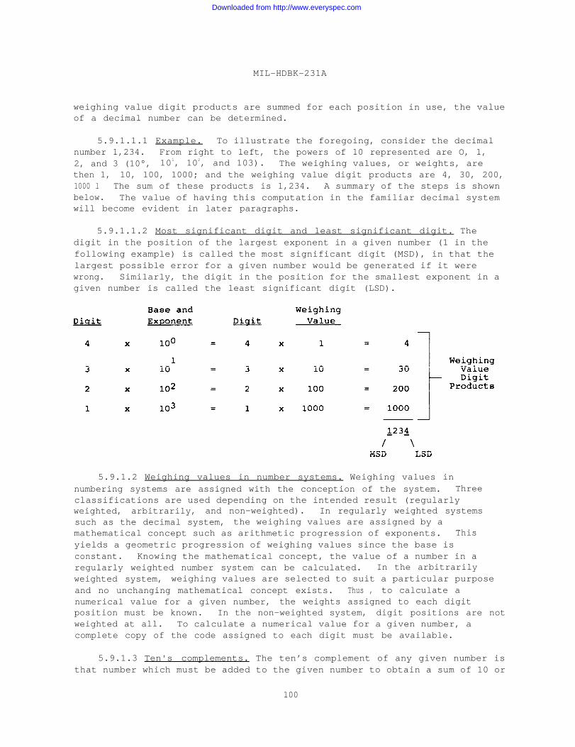
MIL-HDBK-231A
weighing value digit products are summed for each position in use, the valueof a decimal number can be determined.
5.9.1.1.1 Example. To illustrate the foregoing, consider the decimalnumber 1,234. From right to left, the powers of 10 represented are O, 1,2, and 3 (10°, 101, 102, and 103). The weighing values, or weights, arethen 1, 10, 100, 1000; and the weighing value digit products are 4, 30, 200,1000 l The sum of these products is 1,234. A summary of the steps is shownbelow. The value of having this computation in the familiar decimal systemwill become evident in later paragraphs.
5.9.1.1.2 Most significant digit and least significant digit. Thedigit in the position of the largest exponent in a given number (1 in thefollowing example) is called the most significant digit (MSD), in that thelargest possible error for a given number would be generated if it werewrong. Similarly, the digit in the position for the smallest exponent in agiven number is called the least significant digit (LSD).
5.9.1.2 Weighing values in number systems. Weighing values innumbering systems are assigned with the conception of the system. Threeclassifications are used depending on the intended result (regularlyweighted, arbitrarily, and non-weighted). In regularly weighted systemssuch as the decimal system, the weighing values are assigned by amathematical concept such as arithmetic progression of exponents. Thisyields a geometric progression of weighing values since the base isconstant. Knowing the mathematical concept, the value of a number in aregularly weighted number system can be calculated. In the arbitrarilyweighted system, weighing values are selected to suit a particular purposeand no unchanging mathematical concept exists. Thus , to calculate anumerical value for a given number, the weights assigned to each digitposition must be known. In the non-weighted system, digit positions are notweighted at all. To calculate a numerical value for a given number, acomplete copy of the code assigned to each digit must be available.
5.9.1.3 Ten's complements. The ten’s complement of any given number isthat number which must be added to the given number to obtain a sum of 10 or
100
Downloaded from http://www.everyspec.com
MIL-HDBK-231A
a power of 10. The ten’s complement of two is eight, since 8 + 2 = 10.Likewise,
3the ten’s complement of 504 is 496 since 504 + 496 = 1000 = 10 .
The importance of the complementation property of a number lies in the factthat numbers may be subtracted by adding the subtrahend’s complement, thussimplifying any computer techniques used to decode the digital output froman encoder. If the code used in any given encoder has the property of aneasily formulated binary ten’s complement, subtraction in the outputelectronics can be simplified to addition. In general, to find thedifference between any two numbers, add the minuend to ten’s complement ofthe subtrahend and ignore the MSD.
5.9.1.4 Nine’s complement. The nine’s complement is identical to theten’s complement previously described except that the figure nine isutilized and powers of nine are not. The nine’s complement of three is sixsince 6 + 3 = 9. Likewise, the complement of 56 is 43 since 56 + 43 = 99.By utilizing the end-around carry, the MSD thrown away in the ten’scomplement subtraction can be used to arrive at the correct answer in nine’scomplement subtraction. Consider the subtraction problem 496 minus 387.Using rules similar to those for the ten’s complement, we obtain the nine’scomplement of 387 which is 612. Adding, we obtain 496 + 612 = 1108.Removing the MSD from the previous result and adding it to the remainingnumber (end-around carry), we obtain 108 + 1 = 109, the correct answer. Anencoder utilizing a code that is easily formed into the nine’s complement isalso useful in reducing external computer electronics if arithmeticsubtraction is required.
5.9.1.5 Binary system. The binary system is a numbering system basedon a radix of two. Only two-digit values are permitted, usually called zeroand one. A binary number is a number using only two-digit values. (Thedigit value convention of zero and one is used throughout this handbook.)Binary numbers are formed as in the decimal system, by utilizing more digitpositions. Various schemes called codes have been devised to utilize theproperties of binary numbers. These codes (binary codes) are formed byvarying the weighing value of weighing classification to suit the intendedpurpose. Regularly weighted binary codes are usually named by the fourlowest integral weighing values. The number of possible codes is infinite;the number of useful codes, definable; and the more common of these, as theyapply to encoders, discussed herein.
5.9.1.6 Natural bindary numbers. Encoders using a natural binary system(see 5.9.1.9) employ the simplest code for use in arithmetic or comparisoncircuits. (A comparison circuit indicates that A is greater than B or Aequals B.) Natural binary is the most compact binary code since it requiresthe fewest number of symbols (bits) to represent any given span of numbers.It has no redundant or unused code combinations. Numbers coded in naturalbinary are most familiar to people working with computers or digital circuits.For shaft position encoders, natural binary numbers have the disadvantage ofrequiring the simultaneous change of more than one bit when transferringfrom one number to the next, as between 15 (01111) and 16 (10000). Althoughmany techniques exist to cope with the ambiguity problem caused bysimultaneous change, they add to the cost and complexity of the encoder.
101
Downloaded from http://www.everyspec.com
MIL-HDBK-231A
5.9.1.7 Parity bits. Parity bits (tracks) may be added to permitautomatic detection of errors. Numbers coded in natural binary have noredundant or unused code combinations. By adding redundancy, it is possibleto detect or even correct some errors. A simple and useful redundancy isthe addition of a parity bit. This permits detection of single errors. Oddparity occurs when a track is added to the encoder so that an odd number ofcontacts are conducting at every position of the encoder. Even parity isequally convenient to generate, such as an even number of contactsconducting at every position. This concept can be expanded to add oneparity track for each group of contacts. For example, a fifth contact canbe added to each group of four, so that of the total group of five contacts,either one, three, or five (an odd number) are conducting. Taken to thelimit, 100 percent redundancy can be provided so that for every conductingcontact, there is a non-conducting contact. This is the same as true andcomplement output. Parity bits permit automatic checking of the encoderoperation and additional checking of subsequent data handling equipment.Variations on the basic binary number system are highly adaptable toelectrical counting because all common electrical components are two-state(On-Off) devices. Although costly 10-state devices can be made for directprocessing of the more familiar decimal number system, it is moreconvenient, efficient, and economical to perform storage, arithmetic, andlogic operations in binary form and then convert the result to its decimalequivalent for display and human use. In the binary system all numericalvalues can be represented using only two symbols: 1 and 0. Thus, the O canbe represented by an open circuit and 1 by a closed circuit, or vice versa.
5.9.1.8 Binary code 8.4.2.1. The 8-4-2-1 binary (natural or purebinary) code is a regularly weighted code and probably the most familiar ofall binary codes. The natural binary code is similar to the decimal systempreviously described except that a base of two is utilized and only twodigits are permitted. As in the decimal system, each digit position in agiven number has a power or exponent associated with it, but the powers areexponents of the base two. The value of the exponent for any given digitposition is equal to the number of digits to the right of the given digit.Similarly, when read from right to left (the standard in this handbook), theexponents form an arithmetic progression (20, 21, 22, 23, and so on); andthe corresponding weighing values form a geometric progression (1, 2, 4, 8,and so on). If the individual, weighing value-digit products are summed foreach digit position, the value of the corresponding decimal number isobtained. As an example, consider the binary number 0101. From right toleft, the powers of two represented are 0, 1, 2, and 3 (20, 21, 22, and 23).The weighing values are 8, 2, 4, and 8 and the weighing value-digit productsare 1, 0, 4 and 0. The sum of these products is the decimal number 5. Asummary of the steps is shown below.
102
Downloaded from http://www.everyspec.com
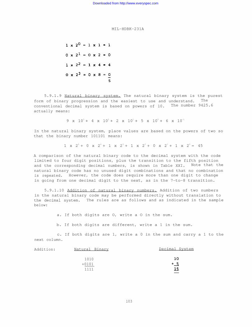
MIL-HDBK-231A
5.9.1.9 Natural binary system. The natural binary system is the purestform of binary progression and the easiest to use and understand. The
conventional decimal system is based on powers of 10. The number 9425.6
actually means:
9 x 10³ + 4 x 10² + 2 x 101 + 5 x 100 + 6 x 10⁻¹
In the natural binary system, place values are based on the powers of two sothat the binary number 101101 means:
1 x 25 + 0 x 24 + 1 x 23 + 1 x 22 + 0 x 21 + 1 x 20 = 45
A comparison of the natural binary code to the decimal system with the codelimited to four digit positions, plus the transition to the fifth positionand the corresponding decimal numbers, is shown in Table XXI. Note that the
natural binary code has no unused digit combinations and that no combinationis repeated. However, the code does require more than one digit to changein going from one decimal digit to the next, as in the 7-to-8 transition.
5.9.1.10 Addition of natural binary numbers. Addition of two numbersin the natural binary code may be performed directly without translation tothe decimal system. The rules are as follows and as indicated in the samplebelow:
a. If both digits are O, write a O in the sum.
b. If both digits are different, write a 1 in the sum.
c. If both digits are 1, write a 0 in the sum and carry a 1 to thenext column.
Addition: Natural Binary Decimal System
1010+01011111
103
Downloaded from http://www.everyspec.com
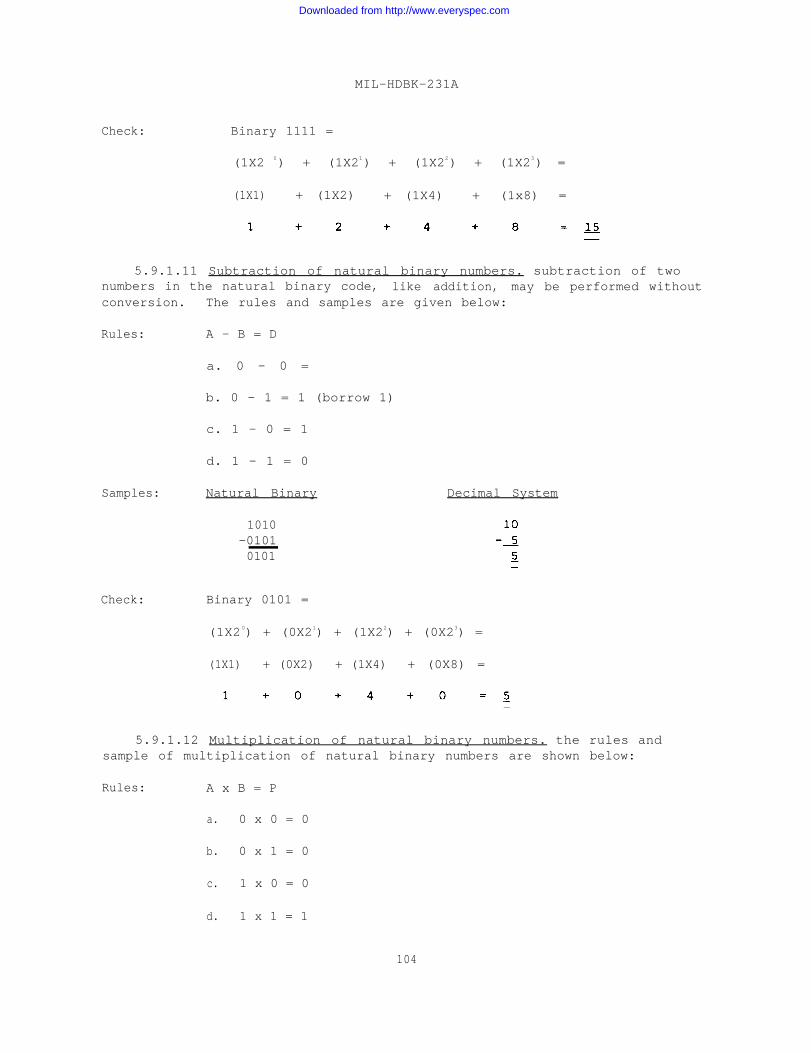
Check:
MIL-HDBK-231A
Binary 1111 =
(1X2 0) + (1X21) + (1X22) + (1X23) =
(1X1) + (1X2) + (1X4) + (1x8) =
5.9.1.11 Subtraction of natural binary numbers. subtraction of twonumbers in the natural binary code, like addition, may be performed withoutconversion. The rules and samples are given below:
Rules: A - B = D
a. 0 - 0 =
b. 0 - 1 = 1 (borrow 1)
c. 1 - 0 = 1
d. 1 - 1 = 0
Samples: Natural Binary
Check:
1010-01010101
Decimal System
Binary 0101 =
(1X20) + (0X21) + (1X22) + (0X23) =
(1X1) + (0X2) + (1X4) + (0X8) =
5.9.1.12 Multiplication of natural binary numbers. the rules andsample of multiplication of natural binary numbers are shown below:
Rules: A x B = P
a. 0 x 0 = 0
b. 0 x 1 = 0
c. 1 x 0 = 0
d. 1 x 1 = 1
104
Downloaded from http://www.everyspec.com
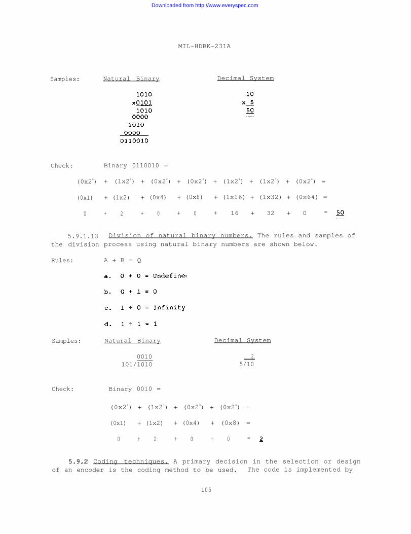
Samples:
Check:
(0x20)
(0x1)
0
5.9.1.13the division
Rules:
Samples:
Natural Binary
MIL-HDBK-231A
Decimal System
Binary 0110010 =
+ (1x21) + (0x22) + (0x23) + (1x24) + (1x25) + (0x26) =
+ (1x2) + (0x4) + (0x8) + (1x16) + (1x32) + (0x64) =
+ 2 + 0 + 0 + 16 + 32 + 0 =
Division of natural binary numbers. The rules and samples ofprocess using natural binary numbers are shown below.
A + B = Q
Natural Binary Decimal System
0010101/1010
25/10
Check: Binary 0010 =
(0x20) + (1x21) + (0x23) + (0x24) =
(0x1) + (1x2) + (0x4) + (0x8) =
0 + 2 + 0 + 0 =
5.9.2 Coding techniques. A primary decision in the selection or design5.9.2of an encoder is the coding method to be used. The code is implemented by
105
Downloaded from http://www.everyspec.com
MIL-HDBK-231A
the pattern of segments on the face of the encoder disc and is dictated inlarge part by the application which, in turn, will determine the category ofencoder to be used. Currently, almost all encoders are of two categories:incremental encoders and absolute (direct reading) encoders.
a. Incremental encoders are designed and constructed so that thepattern on the rotating disc forms a series of uniform marks or opaquelines, each precisely positioned. The output of the encoder istheoretically a series of identical square waves. Each pulse represents asmall fraction of a revolution of the shaft being monitored. Some form ofdigital counter stores the number of counts. The data describes total angleor rotation experienced with reference to an arbitrary starting point.
b. Absolute or direct reading encoders have a disc patternconsisting of a series of concentric tracks, each containing a simplemultiple of the other. Each position of the encoder defines an angularposition in some digital code. The output of the instrument will remainaccurate if turned off and then reenergized at any time in the future. Itrequires no auxiliary storage device.
With either incremental or absolute encoders, the digital code is based on aspecial number system with arithmetic and logic characteristics best suitedto the application. In recent years with the advent of third generationdigital computers, gigantic telemetering systems, and the growing use ofautomation, many number systems and coding techniques have arisen. Tosatisfy each individual requirement, varied codes are available which permiteasy interface with existing systems without demanding elaborate translationor control circuits. Codes used in shaft position encoders can meetrequirements ranging from digitizing a shaft position for decimal visualdisplay to indicating antenna positions for tracking and control of spacevehicles.
5.9.2.1 Incremental code. The incremental code shown in Table XXII isa regularly weighted code limited to two-digit positions. Consequently, itis symmetrical around the 3-to-4 transition since no other combination ofdigits is permitted. The usefulness of the incremental code is notimmediately apparent since any two decimal digits separated by threeintermediate decimal digits are represented by the same binary number (O and4, 3 and 7, and so on) . However, it has the advantage of counter reset,allowing the zero reference point to be any arbitrary shaft position. Theincremental code can be used with up–down counters to accumulate a numberrepresenting shaft position. This code has the advantage that the countercan be reset to zero and thereby shift the zero reference point to anyarbitrary shaft position. It has the disadvantage of being sensitive tonoise and power failure and requiring some additional electronics (up-downdetector and counter). An incremental track is often combined with anabsolute encoder to indicate velocity (count over fixed-time interval) or todetect peaks and valleys.
5.9.2.2 Single contact encoders. A variation of the incrementalencoder is the single contact encoder. The single contact encoder uses a
106
Downloaded from http://www.everyspec.com
MIL-HDBK-231A
two-layer circuit board. The surface of the top layer consists of a seriesof segments (one for each count). Each segment on the top layer connects to
a single conductor of the 18 concentric conductors on the second layer. The
18 conductors are used for 1,000 counts and are connected to set-resetregisters, which in turn operate translating circuits. A single rotating
contact assembly connects power to the segment that corresponds to theangular position. The sequential signals are stored and translated. In the
event of power interruption or for initial turn-on~ a rotation up to amaximum of 20 counts may be required to reset the register. The encoder
must generate a unit distance code, such as Gray code or cyclic decimal, inthe storage register which then is translated to the desired binary code ordecimal. This circuit has an advantage in providing lower torque andinertia than multiple contact encoders. Its disadvantages are:
a. Number of output lines required.
b. Number of turns required to generate a correct output.
c. Number of external circuits required.
5.9.3 Binary decimal system. A binary decimal number is one in whicheach decimal digit is represented by a set of natural binary bits or abinary word. For example, the number 227 can be written as the binarydecimal number 0010 0010 0111.
5.9.3.1 Binary coded decimals. The binary coded decimal (BCD) is amethod of coding decimal numbers in which a group of binary digits is usedto represent each decimal digit. The group is called a “word” and eachindividual binary digit is called a bit (contraction of Binary digit). Agroup of four binary digits representing a decimal digit (or any otherquantity defined by the group) is called a four-bit word. The BCD can be
coded in any binary code, the most common regularly weighted code being thenatural BCD (8-4-2-1 BCD).
5.9.3.2 BCD background. Some system applications require the displayof output data to be monitored and used by operating personnel. In such
cases, a primary performance requirement is conversion of output data to aform that can be rapidly and accurately understood by human operators. Acommon coding method used to satisfy this need is the BCD. Using BCD, the
familiarity of Arabic decimal numbers can be combined with the usefulproperties of the binary system. This approach is used as an efficientcompromise to derive maximum benefit from both machine and human capability.Although some loss in compactness and some added complexity in thearithmetic circuits are required, BCD numbers are easy to manipulate sincethey are similar to decimals.
5.9.3.3 BCD implementation. The BCD code is similar to the naturalbinary code except that each decimal decade is represented by a four-bitbinary word. These bits can be weighed in various ways. The two mostpopular being the 8-4-2-1 (natural binary) and 4-2-2-1 (cyclic) codes.Figure 102 illustrates the 8-4-2-1 BCD code.
107
Downloaded from http://www.everyspec.com
MIL-HDBK-231A
5.9.3.4 8-4-2-1 BCD’s. The 8-4-2-1 BCD is a binary code in which only10 digits of the decimal system are coded. Each decimal digit isrepresented by four binary digits (bits). Any decimal number is expressedby groups of bits, the number of which is equal to the quantity of digits inthe decimal number. The BCD output is desirable when external decimal-to-binary and binary-to-decimal conversions are to be held to a minimum. With8-4-2-1 BCD encoder output, only 10 conversion circuits are required fordecimal display from computers, one for each decimal digit. The 8-4-2-1 BCDcode is shown in Table XXIII. Note that six possible digit combinations arewasted.
5.9.3.5 Bnary coded octal. The binary coded octal system shown inTable XXIV is a BCD in which the first eight digits of the decimal systemare coded. Each decimal is represented by three bits. Any decimal numberis expressed by three-bit words, one for each decimal digit. The chiefadvantages of this system are the ease with which a mental conversion fromoctal to decimal can be made, the reduction in electronics in that onlythree bits are required, and no unused combinations exist.
5.9.3.6 7-4-2-1 BCD’s. The 7-4-2-1 BCD is a system similar to the8-4-2-1 BCD and is shown in Table XXV. The 7-4-2-1 code is a power savingcode that requires only two “on” or “one” conditions to represent anydecimal digit. Encoder usage of this code is limited, and it is shown hereto illustrate the diverse number of BCD codes that exist.
5.9.3.7 Two-out-of-seven binary codes. The two-out-of-seven binarycodes are a series of regularly weighted codes which have in common seven-bit words. As many excess binary digits are available, they are useful inerror checking. A sample of two-out-of-seven codes is described in 5.9.3.8.
5.9.3.8 Biquinary coded decimals. The biquinary coded decimal is a BCDcode utilizing seven-bit words to represent the decimal digits. The code isregularly weighted with values of O, 5, 4, 3, 2, 1 and is shown inTable XXVI. Since each coded decimal contains exactly two 1’s, errors maybe easily detected by simple comparison circuits in the externalelectronics. Variations exist in biquinary codes. One such deviation isthe regularly weighted (8-6-4-2-0) odd-even biquinary coded decimal whichhas only six bits per word, or the biquinary code which only differs indigit designation. These codes are also shown in Table XXVI.
5.9.3.9 Two-out-of-five binary codes. The two-out-of-five binary codesare a group of codes that are similar to the two-out-of-seven codes exceptthat five-bit words are used. Again, the error checking potential of thecode is based on having an even number of 1’s for any decimalrepresentation. A two-out-of-five code is shown in Table XXVII forreference. The weighted values for this particular code are 7, 4, 2, 1, 0,with zero being a parity check bit.
5.9.4 Nonweighted binary codes. Nonweighted binary codes, as discussedpreviously, have no weight assigned to the various digit positions. The
108
Downloaded from http://www.everyspec.com

MIL-HDBK-231A
particular binary digit sequence assigned to any given code in this group,then, is assigned to serve a special purpose. These purposes are discussedin the following paragraphs and may be classified as follows:
a. Cyclic codes - reflected or nonreflected.
b. Noncyclic codes - reflected or nonreflected.
c. Combination codes - variations of any combination of codes andcode characteristics.
Table XXVIII presents the notation and progression for five common binarysystems and their decimal equivalent.
5.9.4.1 Cyclic codes. Cyclic codes are a group of nonweighted codeswhich possess the property of requiring only one bit to change when goingfrom one digit to either adjacent digit (monostrophic or unit-distancecode) . For the decimal system, a cyclic code can be formed by changing thenumbering system to count in cyclic decimal as follows: 1, 2, 3, 4, 5, 6,7, 8, 9, 19, 18, 17, 16, 15, 14, 13, 12, 11, 10, and so on. The two digitchange between 9 and 10 is thereby avoided. Binary cyclic codes are formedby assignment of the bits in a monostrophic manner. Cyclic codes can bereflected or nonreflected. In general, reflected codes utilize a pattern toform the code such that the same binary word or group of bits, less the MSD,represents two decimal numbers numerically equidistant from a reflectionpoint. Numbers above and below the reflection point are differentiated bythe MSD. Nonreflected codes have no such pattern.
5.9.4.2 Cyclic binary or gray code. The cyclic binary code is derivedby considering the corresponding natural binary numbers and applying thefollowing rule: Proceeding from left to right, copy the natural binarynumber except complement any digit immediately preceded by a “l” in thenatural binary number. For example, the natural binary number 1010 can betransformed to the cyclic binary number 1111 by applying the above rule.Note that in Table XXVII there is only a one bit change between any twosuccessive decimal representations. The Gray code is a typical reflectedcyclic code of major importance and is shown in Table XXIX. Note that theGray code is, less the MSD, symmetrical around the seven-eight transitionand that only one digit must change in going from any given decimal numberto the succeeding number. The Gray code is reflected and is monostrophic.The code, although only shown for 15 decimal digits, can be expanded asrequired. For special applications, the properties of the Gray code areused in combination with codes such as the Excess-3 BCD. In these cases,the resulting codes are no longer reflected. Refer to combination codes forfurther information.
5.9.4.3 Gray code - implementation. Although Gray code is a binarynotation system, it must be decoded to derive its natural binary equivalentfor most applications. This is usually a function of the interface circuitsbetween the encoder and the parent system or a task performed by the outputfunction of the encoder. However, a clearer understanding of the details of
109
Downloaded from http://www.everyspec.com
MIL-HDBK-231A
Gray coding may be gained from the details of the decoding process. Therule for converting Gray code notation to its natural binary equivalent isthat the most significant 1 (the 1 bit with the highest decimal equivalent)remains unchanged and each successive digit becomes complemented (a 1becomes a O and a O becomes a 1) for as many times as there are 1’spreceding it in the Gray code word. Referring to Figure 103 and observingthe transition to the decimal value 21, we find the notation would be 11111.Using the basic rule, the decoding process would be as follows:
a. The most significant bit, with a weight of 24, or16, 1 is 1 and remains unchanged.
b. The next digit, with a weight of 8, is a 1 and iscomplemented once and becomes a 0.
c. The next digit, with a weight of 4, is a 1 and iscomplemented twice, becoming a 1.
d. The next digit, with a weight of 2, is a 1 and iscomplemented three times, becoming a 0.
e. The last digit, with a weight of 1, is a 1 and iscomplemented four times, becoming a 1.
f. Adding the weights of these bits = 21
Therefore, the decimal equivalent of the Gray code word 11111 is 21 and thebinary equivalent is 10101. Due to the difficulty and accuracy limits inthe mechanical alignment of sensor contacts, encoders using natural binarycode can produce ambiguous outputs at the point of transition between twocoded values. Various methods to overcome this fault have been developed,and one of the earliest was the use of the cyclic binary or Gray code (namedafter its inventor). The pattern arrangement for Gray code (see Figure 103)ensures that only one bit changes state for each progression as shown inFigure 104. Thus, a single row of sensors, positioned to within one digitof accuracy, will produce an output with a maximum error limited to one bit.Since the inherent error in any encoder is one bit, the overall accuracy ofthe encoder system remains essentially the same. This inherent error occursbecause the detecting sensors cannot discriminate between the start and theend of a given segment on the encoder disc.
5.9.4.4 Gray code - design characteristics. Gray code has theadvantage of being monostrophic; that is, a unit distance code sinceadjacent numbers appear on adjacent squares (such as at unit distance) on aVietch diagram. Therefore, Gray code requires only a single bit to changewhen passing from any number to the adjacent number. This featuresimplifies the encoder code pattern and thereby reduces the cost of theencoder. Gray code is easily translated to natural binary numbers by thefollowing rules:
110
Downloaded from http://www.everyspec.com
MIL-HDBK-231A
a. The most significant natural binary bit is identical to themost significant Gray bit.
b. If the nth natural binary bit is 0, the (n-1)th natural bitis identical to the (n-1)th Gray bit.
c. If the nth natural binary bit is 1, the (n-1)th natural bitis the opposite of the (n-1)th Gray bit.
In Boolean terms, conversion of Gray code to a natural binary equivalent isan "exclusive OR" gate function expressed as:
The (n-1)th binary bit is True (logical “1”) if the (n-1)th Gray bit isTrue (logical “1”) and the nth binary bit is False (logical “0”), or if the(n-1)th binary bit is True.
5.9.5 Cyclic decimal code.
5.9.5.1 Cyclic decimal - background. Another technique, developed toovercome the basic problem of output ambiguity, is the modification of the
standard Arabic decimal system to a cyclic decimal progression as shown onFigure 105. Cyclic decimal is similar to Gray code in that only a singlebit is changed in progressing from any number to the adjacent value. This
technique provides a code that requires only one switching change between
adjacent numbers. The Arabic number system, modified to the cyclic decimal
system can then be expressed in a binary form with a group of four binaryunits representing each decimal integer. This code can be conveniently
translated from cyclic to Arabic decimal form as part of the encoder outputfunction. The operations internal to the encoder can be performed in a non-ambiguous binary code and an output provided in a standard Arabic decimal
format, either most significant or least significant digit first asdetermined by overall system demands.
5.9.5.2 Cyclic decimal - implementation. The rules for translating
from Arabic decimal to cyclic decimal are as follows:
a. An Arabic decimal digit that follows an even Arabic digit isnot changed.
b. An Arabic decimal digit that follows an odd Arabic digit ischanged to the nine’s complement when expressed in cyclic decimal.
c. The most significant digit of any number is not changed sinceit is understood to follow a zero.
The rules for translating from cyclic decimal to Arabic decimal are similar.The odd or even digit used to determine the nine’s complement requirement isalways taken from the next more significant Arabic digit. In the binary
111
Downloaded from http://www.everyspec.com

MIL-HDBK-231A
coding process (see Figure 105), each of the cyclic decimal numbers isrepresented in the form of a 4-bit binary word. The four bits (A, B, C andD) have no numerical weight or numerical value. The basic code counts onlyto decimal 10 by using discrete combinations of the four bits, as shown onFigure 105. The cyclic decimal code has the general advantagecharacteristic of monostrophic (unit distance) codes including highresolution, simplicity, and mechanical efficiency due to lower reflectedinertia. However, this approach has the disadvantage of requiring that alldetection sensors make and break the full value of voltage and currentrequired by the load, which has an adverse effect upon encoder service lifeand reliability.
5.9.5.3 Cyclic bnary decimal. The cyclic binary decimal system is acombination of cyclic binary and binary decimal concepts. Each decimaldigit is represented by a set of cyclic binary bits or a cyclic binary word.These systems can be used separately or in combination as the cyclic binarydecimal.
5.9.5.4 Coding. Coding is the process of selecting the best numbersystem for a given application and implementing the selected system in theform of a patterned encoder disc. As the disc rotates in response to aninput shaft variable, the shaft position is represented by the relativeposition of the segments of the disc. The code determines the form of theencoder output.
5.9.5.4.1 Natural binary. A pattern representing a typical 5-bitnatural code is shown on Figure 106. The topmost track, called the LeastSignificant, has a weight of 1 or 0 representing 2°. The second track hasa weight of 2 or 0 representing 21. The third has a weight of 4 or 0representing 22. The fourth track has a weight of 8 or O representing 23,and so on. By examining this pattern, it can readily be seen that if a lineof sensors were placed vertically across this pattern and the correctweights were assigned to each track, it is then possible to derive thedecimal equivalent of the binary number by adding the tracks. The sum ofthese numbers would be the decimal number represented by the binary word.Referring to Figure 106, if a line of contacts were placed across thepattern representing the binary word 10101, conduction would occur oncontacts 1, 4 and 16. The sum of these numbers would be the decimal number21 which is the equivalent of that binary word.
5.9.5.4.2 Gray or cyclic binary. Other basic number systems aresimilarly coded. Another example of an elementary disc pattern is shown onFigure 103 which depicts a typical 5-bit Gray code or Cyclic Binaryimplementation. The pattern arrangement is the same regardless of thedetection technique. For a contact encoder, the dark areas of the patternsshown on Figures 106 and 103 would be conductive while the light areas wouldbe insulating material. In an optical system the pattern would consist oftransparent and opaque areas, and in a magnetic encoder disc the dark areaswould be segments of magnetized ferritic material. The selected numbersystem is coded onto the disc in accordance with the desired detectionscheme.
112
Downloaded from http://www.everyspec.com
MIL-HDBK-231A
5.9.5.4.3 BCD. The first 10 binary numbers are used to represent the10 Arabic number symbols. Each decimal integer or decade is represented bya group of four binary units and each decade is considered separately. The
units, tens, hundreds, thousands, and so on of the decimal number are eachrepresented by a separate group of four bits. Table XXVIII lists thenatural BCD equivalent of the decimal values from 0 to 17.
5.9.5.4.4 Cyclic BCD. Because of ambiguity problems inherent inimplementing any code based on natural binary numbers, a cyclic BCD orcyclic decimal code also has been developed. This code employs the samebasic approach as natural BCD coding except that the individual binary unitsin each group of 4 bits are weighted 4-2-2-1 as shown on Figure 107. Thesame rules for decoding apply as used for Gray code; however, one additionalstep is required to derive a decimal equivalent. Using the decimal value 21as an example, Figure 107 shows the cyclic BCD equivalent as the binarywords 0011 and 0001. Converting from Gray code yields the binary words 0010and 0001 which, in turn, is the same as the natural BCD notation.
5.9.5.5 Nonreflected cyclic codes. Nonreflected cyclic codes are alsouseful for encoder applications and usually originated to solve specificproblems. Assignment of logical “1’s” and “0’s” is usually at random. TOillustrate such a code (29 x 109 possible combinations), consider a solutionto the following design criteria:
A binary code for a 10-digit system which
a. allows the nine’s complement to be formed with a one-digitchange,
b. in the last bit, minimizes power supply requirements bylimiting the number of “On” circuits to three per decimal digit for anynumber in the code (1111 is forbidden),
c. restricts the use of 0000 so that power failure can bedetected, and
d. is munostrophic.
One code using BCD’s and a cyclic decimal system is shown in Table XXX. Thecode is used successfully in encoders.
5.9.6 Noncyclic codes - nonreflected codes.
5.9.6.1 Excess-3 code. The Excess-3 is a nonreflected code of majorimportance due to the fact that it is self-complementing. The Excess-3 codeis shown in Table XXXI with the method of derivation. As shown in thetable, the Excess-3 code is formed by selecting the 8-4-2-1 binary codeddecimal equivalents of decimal numbers 3 through 12, leaving the first 3digits of the 8-4-2-1 code in excess (not used). Note that if the bits ofany Excess-3 number are inverted (1’s for 0’s and 0’s for 1’s), this number
113
Downloaded from http://www.everyspec.com
MIL-HDBK-231A
also appears in the code. If the process is continued for digits zerothrough four, it becomes apparent that the code is a mirror image about thefour-five transition. Also, note that if the digits of an Excess-3 numberand its inversion are summed, the result is always equal to nine. TheExcess-3 code is self-complementing, making a subtraction problem possibleby addition using the nine’s complement method without computer memoryprogramming of the complements. Forbidden words of the code are excellentfor error checking, but translation to decimal requires a subtractercomputer circuit.
5.9.6.1.1 Example. The Excess-3 decimal code is illustrated onFigure 108. This code has several advantages where direct input to acomputer is desired. Excess-3 decimal code is similar to the 8-4-2-1 BCDcode except that the number has three added to it; that is, the digit O isrepresented by 3, 1 by 4, 2 by 5, and so on. This code produces a well-balanced pattern with the added feature of being a natural nine’s complementpattern. Thus, 9 (1100) is the complement of 0 (0011), 1 (0100) is thecomplement of 8 (1011), 2 is the complement of 7, 3 of 6, and 4 of 5. Thisfeature is useful where a plus or minus count is desired. For a plusnumber, the natural number is used; for a minus number, the numbers from 9are complemented, producing a decreasing count from the same disc orpattern.
5.9.6.1.2 Excess-3 natural binary. The Excess-3 code shown inTable XXVIII is the same as natural binary except that it has been displaceddownward three places, making the actual natural binary representation for 3correspond to 0. The numbers 0 to 9 are complementary; for example, 0replaces 1 and 1 replaces 0. The same is true for 2 and 7, 3 and 6, 4 and5. Subtraction of any number from 9 is, therefore, the same as the purebinary representation of that number except that the 0’s and 1’s areinterchanged.
5.9.6.2 Excess-3 BCD. The Excess-3 BCD is a combination of theExcess-3 code and BCD techniques previously described. The code is shown inTable XXXI along with the Excess-3 code.
5.9.7 Combination codes. Combination codes are formed by using two ormore existing codes, each having desirable characteristics or meetingspecific needs. Two examples are given in the following text.
5.9.7.1 ICAO code. The ICAO altitude reporting code (formerly MOA-Gillham code) is a combination code designed for automatic reporting ofaircraft altitude. The code is designed to report in either 500- or 100-foot increments to meet both European and United States standards. The ICAOcode is a combination of a reflected cyclic code (Gray) and a nonreflectedcyclic code that allows altitude reporting from -1,200 feet to 127,000 feet.The encoder design may be either single- or multi-turn; the multi-turn beingshown in Table XXXII by a particular commutator code bit arrangement. The500-foot increments are in Gray code spaced symmetrically around 500-footaircraft altitudes. A decoded Gray of 3 (left-hand column) indicates anominal aircraft altitude of 500 feet, actually between 250 and 750 feet if
114
Downloaded from http://www.everyspec.com
MIL-HDBK-231A
both the code increment and code transition points are included. (Thisparticular accuracy is sufficient in many cases as aircraft fly east-westpaths on specific 1,000-foot bands and north-south on others.) The 100-foot increments required by airport traffic controllers are identified by athree-bit nonreflected cyclic code. The code is derived such that any 100-foot increment retains the same bit configuration (C1, C2 and C4) whenoccurring at a Gray code transition, and thus is based on the odd-evencharacteristics of the decoded Gray code. This is shown in the table foraltitudes of 250 ft, 750 ft, 1,250 ft, 1,750 ft, and so on. The ICAO codeis entirely monostrophic in that no more than one bit is ever required tochange for any altitude increment. A two-bit change is then a forbiddenoccurrence, indicating an encoder or transponder error to the aircrafttraffic controller. Table XXXIII indicates the forbidden bit changes forthe 100-foot code. The entire code through 127,000 feet with a typicalcommutator (disc) design is shown on Figure 109.
5.9.7.2 ICAO code - background. The ICAO code was developed by theBritish Air Ministry for the reporting of altitudes in automatic flightcontrol. When first developed, it contained eight bits of Gray coderepresenting 256 increments of 500-feet for a total of 128,000 feet. The500-foot increment was not small enough for use in the continental UnitedStates, and these increments were further divided into 100-foot increments.More bits were added to the code, thereby modifying it. It was then adoptedby the International Civil Aviation Organization (ICAO). This code is ofparticular interest because of the new programs for automatic altitudereporting, and because it is a prime example of a class of useful, specialpurpose, ambiguous coding. ICAO code features the combined use of cyclicdecimal coding for the least significant decimal character and Gray code forthe higher order bits. The details of the progression and pattern for theICAO code are not standard throughout the encoder industry, although astandardized altitude transmission code is produced as an output. Generally,the variations among manufacturers occur in the means of encoding the leastsignificant bits (100-foot altitude increments). Some ICAO encoders use afour-bit code for the 100-foot data while others accomplish the sameencoding task with a three-bit word. Both approaches are discussed below.
5.9.7.3 ICAO code - implementation. The progression and pattern forICAO code implementation using Gray code and a four-bit cyclic decimal wordare shown on Figure 110. The altitude unit’s and ten’s decades are assumedto be zero and are not included in the disc pattern. The least significantbits represent the hundred’s decade, and four bits (A, B, C, and D) of astandard cyclic decimal code are used to code this value. The odd or evendecimal configuration of the Gray coded most significant decades (500-footaltitude increments) determines the hundred’s decade output count. If theGray code count is odd, the D bit of the cyclic decimal code iscomplemented. Inversely, if the Gray code count is an even decimal value,the D bit is not complemented. This complementing operation decodes thecyclic decimal output to an equivalent Arabic decimal code. The Gray codedwords are incremented by 1 for every 1,000 feet of altitude increaserequiring external logic and arithmetic translation circuits to perform thefollowing operations:
115
Downloaded from http://www.everyspec.com
MIL-HDBK-231A
a. Determine the odd or even configuration of the Gray code outputand translate Gray code to decimal notation.
b. Translate the cyclic decimal output to Arabic code. If Graycode is odd, complement the D bit of encoder output; if Gray code is even,do not complement the D bit of the encoder output.
co Translate the Arabic code to decimal and multiply by 100.
d. Multiply the decimal value of the Gray code count by 1000.
e. Add the 100’s to the 1000’s.
f. Subtract 1,200 from the sum to obtain the altitude in feet.The ICAO code is offset by 1,200 feet from the zero position to permiteffective outputs from -1,200 feet to 127,000 feet, typically.
To apply these rules to a typical situation, suppose an altitude of 1,500feet were to be transmitted. The Gray code output would be 11000 and thecyclic decimal output would be 0101. As shown on Figure 104, the Gray codeoutput would be 2, an even integer. The D bit of the cyclic decimal outputis, therefore, not complemented and would translate to an Arabic decimalvalue of 7 (see Figure 105). Multiplying 2, the most significant value, by1,000, and 7, the least significant value, by 100, and adding the productswould yield:
(2 x 1,000) + (7 x 100) = 2,000 + 700 = 2,700
Then, subtracting 1,200 from this sum:
2,700 - 1,200 = 1,500
The decoding process would be similar for other altitude values as shown onFigure 110. Another typical implementation of ICAO or Gillham code using athree-bit cyclic decimal word for the least significant value is shown onFigure 111. As in the previous four-bit example, the code has no particularweighting of bits and is decoded by bit position as shown on Figure 112.The 100-foot increment table is used on Figure 112 in conjunction with theassociated Gray code word. If the 1’s in the Gray code word are odd, theodd column of the table is used and if even, the even column is used.
5.9.8 Gray coded Excess-3 BCD. The Gray coded Excess-3 BCD is acombination code derived from the Excess-3 BCD and Gray codes. Thecombination retains the properties of both codes which are indicated below.
116
Downloaded from http://www.everyspec.com
MIL-HDBK-231A
Property
Easily formed nine’s complement (one-bit inversion)
Plus-minus operation with multi-turn encoders bycomplementation in the minus range
Code Origin
Excess-3 BCD
Excess-3 BCD
Cyclic or monostrophic Gray
Easy translation to natural binary Gray
Easy manipulation (familiarity with decimals) Excess-3 BCD
High count density possible Gray
The code is formed by adding 3 to the particular Arabic digit and encodingthis result in Gray BCD code. For example, to encode the Arabic decimal 2,
add 3, and encode in Gray.
2 + 3 = 5
5 = 0111 (Gray-coded Excess-3 BCD)
The code is shown in Table XXXIV. Note the transition between 9 and 10 or19 and 20.
5.9.9 Two-out-of-five codes.
5.9.9.1 Two-out-of-five codes - backmound. Two-out-of-five, or
biquinary codes, provide a useful technique for applications requiringdisplay of decimal information, especially if a parity check is desirable.This code can be used with such devices as typewriters, adding machines, orvisual indicators which require a direct decimal input. If the encoderoutput is only required to operate peripheral equipment and the output doesnot need to be stored or transmitted, it is often more efficient to generatethe required decimal signals directly from the encoder, thus eliminating theneed for intermediate interface circuits. There are a number of variationson the basic biquinary code which can be combined with processing circuitsto provide decimal signals in a directly usable form.
5.9.9.2 Two-out-of-five codes - implementation. The two-out-of-fivecode derives its name from the fact that a five-bit binary word is used torepresent each of the 10 basic Arabic decimal numbers (0 through 9). Asshown on Figure 113 and Table XXXV, two-out-of-five bits in each word arealways 1’s and the remaining bits are always 0’s. Except for the decimalvalue zero, the first four bits are weighted 1, 2, 4, 7 and the fifth bit isused to provide even parity. Where direct decimal outputs are required, aseparate output line must be provided for each of the 10 Arabic numerals.This means that 10 lines are required for each decimal digit; for example, athree-place output would be carried on 30 output lines. Direct decimaloutput adds complexity to the encoder design. A compromise, almost as
117
Downloaded from http://www.everyspec.com
MIL-HDBK-231A
useful in operating decimal output devices, is the odd/even biquinary codeshown on Figure 114. This code consists of the standard five biquinarycoded bits plus an odd/even selector bit. The selector bit denotes the oddor even configuration of the output count. This technique reduces thenumber of output lines required for direct decimal readout from 10 to 6.Figure 115 is a typical odd/even biquinary output circuit; the odd/even busselector connects the odd bus to ground for odd numbers and connects theeven bus to ground for even numbers.
5.9.10 Special purpose codes.
5.9.10.1 Special purpose codes - background. For various specialpurpose applications, unique number systems have been developed to deriveunit distance codes, codes that can be easily complemented, or codes thatproduce plus-minus outputs. Three such applications are time and angleencoders, multispeed encoders with plus-minus spans, and center-zero single-turn encoders. These situations are typical of the design problems whichmust be solved to make effective use of encoders in modern systems.
5.9.10.2 Special purpose codes - implementation time and angle. Time(hours, minutes and seconds) or angle (degrees, minutes and seconds) employspecial number systems that require special codes either to obtain a unitdistance code or to obtain a code that is easily complemented. A unitdistance code for the ten’s digit of minutes (0-5) or seconds (0-5) that canbe complemented by inverting a single bit is shown in Table XXXVI. Ingeneral, an easily complemented unit distance code for any even-numberedspan can be formed by the following rules:
a. Subtract the span from the next higher integral power of 2.
b. Divide this difference by 2 and add the result to the originalgroup of numbers.
c. Encode the new group in Gray code.
For example, to obtain a unit distance code for 0 to 23 hours that may becomplemented by inverting a single bit, subtract 24 from 34 (which is 25)and add half the difference (4) to the original numbers. Table XXXVIIdetails a time and angle code based on the above principle.
5.9.10.3 Plus-minus spans with multispeed encoders. To obtain plus-minus number systems, it is convenient to use a code which is easilycomplemented to obtain negative numbers. One difficulty with this techniqueis that the complementing operation produces two zero positions, +000 and-000. This occurs since the complement of 999 is 000. Double zeros resultin an additional error of 0.5 quantum. To avoid the double zero, it isnecessary to use twice as many tracks and contacts on the high-speed discsand to switch from one set of contacts to the other at zero. This type ofconstruction puts no restriction on the number system or coding used,although it is relatively expensive.
118
Downloaded from http://www.everyspec.com
MIL-HDBK-231A
5.9.10.4 Center-zero single turn encoders. A similar problem ariseswith single-turn encoders which use a unit distance code such as Gray code,and require a plus-minus output. If the error due to a double width zerocannot be accepted, a special pattern can be made. This pattern has both+000 and -000, but each sector is only 0.5 normal quanta in width (angulartravel) so that no error is added because of the plus-minus number system.
5.9.11 Code selection criteria.
5.9.11.1 BCD versus binary. Use of BCD versus binary is usuallydetermined by system considerations. However, for encoder use BCD has30 percent more contacts and torque and is slightly larger and moreexpensive. The 30 percent redundancy can be used for error detection (sensefor unused codes).
5.9.11.2 Monostrophic versus weighted codes. Monostrophic encodershave fewer contacts, require no diodes for the first disc, and are generallysmaller and less expensive than encoders employing the more familiarweighted binary of BCD codes. They have minimum torque and inertia. They
are easier to use if long cables are necessary and have the simplest storagecircuits. However, encoders with weighted binary or BCD codes should beconsidered in control systems using comparators or systems employingarithmetic circuits or where it is necessary for the encoder to drive heavyloads (more than 5 milliamperes or 30 volts). When the system rewires theconnection of one out of two or more encoders to a common data bus orstorage register, the absence of diodes in single-turn cyclic decimal orGray code encoders is no longer an advantage. Adding diodes for paralleloperation may tip the scale in favor of weighted codes. Multi-turn Graycode or cyclic decimal encoders employ diode OR gates for all except thefirst high-speed disc. In this instance, there is less reason to change toweighted codes.
5.9.11.3 Direct decimal. Decimal or biquinary encoders have anadvantage in simple systems where no storage, comparison, or arithmeticoperations are required and where cable cost or size is not important.Typical applications are indicating or direct printout systems. Decimalencoders are usually much larger than BCD or biquinary encoders.
5.9.12 Encoder logic. The following paragraphs describe the logicequations, symbols, and diagrams used in encoder circuitry, Basic toencoder usage is the fact that output is in terms of logical 1’s and 0’s.Circuit design must discriminate between a one or zero for any given digitexisting or not existing. The following digit requires this samedetermination, and the position summation of these individual digit valuesdetermine the value of encoder output. These digit relationships are bestexpressed using the conjunctive of Boolean algebra. The portion of Booleanalgebra covered herein, then, is limited to the conjunctive relationships ofdeductive Aristolean logic as formulated by George Boole in 1847. Thislogic is the study of single-valued functions as represented by the wordsAND, OR, AND NOT (NAND), and OR NOT (NOR). A summary of the Boolean lawsand functional operators (symbols) is shown in Table XXXVIII.
119
Downloaded from http://www.everyspec.com
MIL-HDBK-231A
5.9.12.1 Logic functions. Consider a typical logic equation orfunctions such as:
The equation is read "if a and if b, then c". The equation states twoconditions which must be present in order to obtain a certain result. If aand b are present, c is implied. The equation can be presented pictoriallyas shown on Figure 116 by a series circuit. If, and only if, both switchesA and B are closed can lamp C illuminate. The foregoing illustrates the ANDfunction. If the AND function logic equation is inverted to the negative orNOT sense, the equation is still true. Inversion of the equation yields:
The equation is now read “if not a and not b, therefore not c”. Byexamining the diagram on Figure 116, the following equations are also true.The equations were already implied by the foregoing (if and only if).
All the above equations, although logically true by examination of thediagram, are actually derived from the Boolean rules of inference, two ofwhich are shown in Table XXXVIII. Nineteen such rules, not necessarilyindependent, form a full complement of rules for inference. Note that thedefinition of the AND gate (Figure 116) allows the circuit to perform thefour equations previously discussed. With a rearrangement of the pictorialcircuit, the inclusive OR function can be expressed as shown on Figure 117.The inclusive OR function logic equation is:
a + b = c
The equation is read "if a or if b, then c". As shown on Figure 117, ifswitch A or if switch B is closed, then lamp C can illuminate. Theexclusive OR logic equation is:
The equation is read "if a and not b, or if not a but b, then c." It meansthat c occurs if, and only if, either a or b, but not both, are present.The exclusive OR function is similar to a hall light in a house controlledfrom either upstairs or downstairs. When the upstairs switch is used toturn the light on, the downstairs switch will turn the light off. Theexclusive OR circuit will translate parallel Gray code encoder output tonatural binary code. Figure 118 illustrates this logic function.
120
Downloaded from http://www.everyspec.com
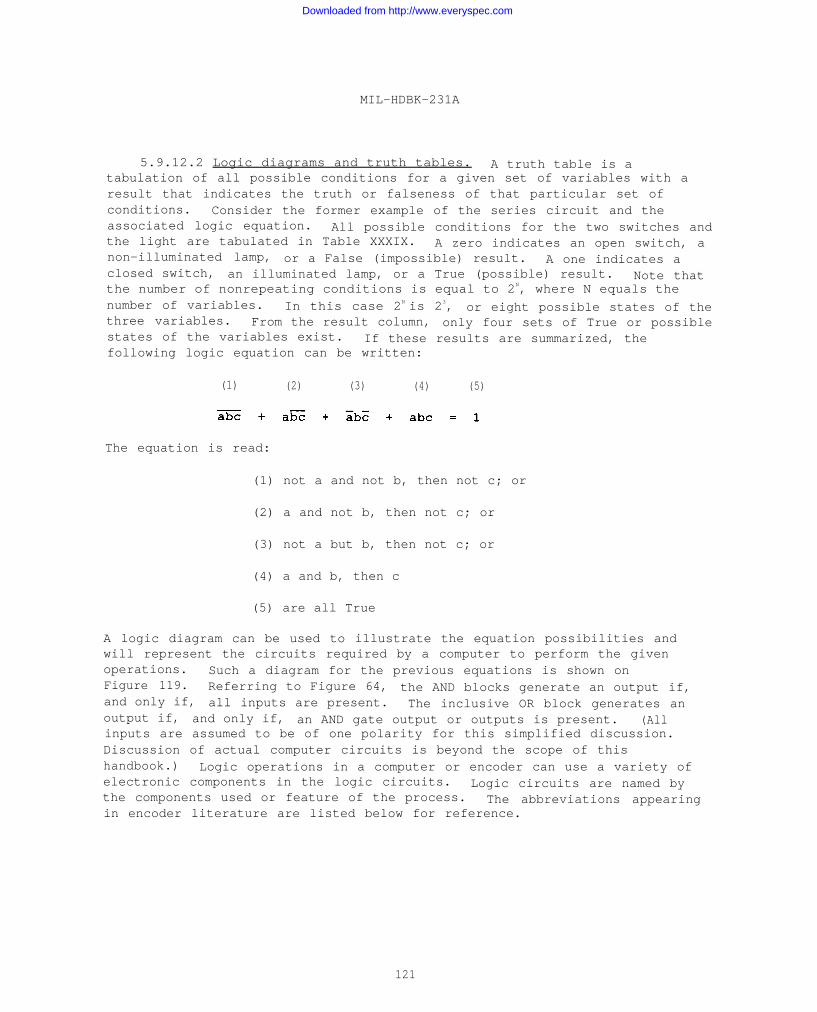
MIL-HDBK-231A
5.9.12.2 Logic diagrams and truth tables. A truth table is atabulation of all possible conditions for a given set of variables with aresult that indicates the truth or falseness of that particular set ofconditions. Consider the former example of the series circuit and theassociated logic equation. All possible conditions for the two switches andthe light are tabulated in Table XXXIX. A zero indicates an open switch, anon-illuminated lamp, or a False (impossible) result. A one indicates aclosed switch, an illuminated lamp, or a True (possible) result. Note thatthe number of nonrepeating conditions is equal to 2N, where N equals thenumber of variables. In this case 2N is 23, or eight possible states of thethree variables. From the result column, only four sets of True or possiblestates of the variables exist. If these results are summarized, thefollowing logic equation can be written:
(1) (2) (3) (4) (5)
The equation is read:
(1) not a and not b, then not c; or
(2) a and not b, then not c; or
(3) not a but b, then not c; or
(4) a and b, then c
(5) are all True
A logic diagram can be used to illustrate the equation possibilities andwill represent the circuits required by a computer to perform the givenoperations. Such a diagram for the previous equations is shown onFigure 119. Referring to Figure 64, the AND blocks generate an output if,and only if, all inputs are present. The inclusive OR block generates anoutput if, and only if, an AND gate output or outputs is present. (Allinputs are assumed to be of one polarity for this simplified discussion.Discussion of actual computer circuits is beyond the scope of thishandbook.) Logic operations in a computer or encoder can use a variety ofelectronic components in the logic circuits. Logic circuits are named bythe components used or feature of the process. The abbreviations appearingin encoder literature are listed below for reference.
121
Downloaded from http://www.everyspec.com
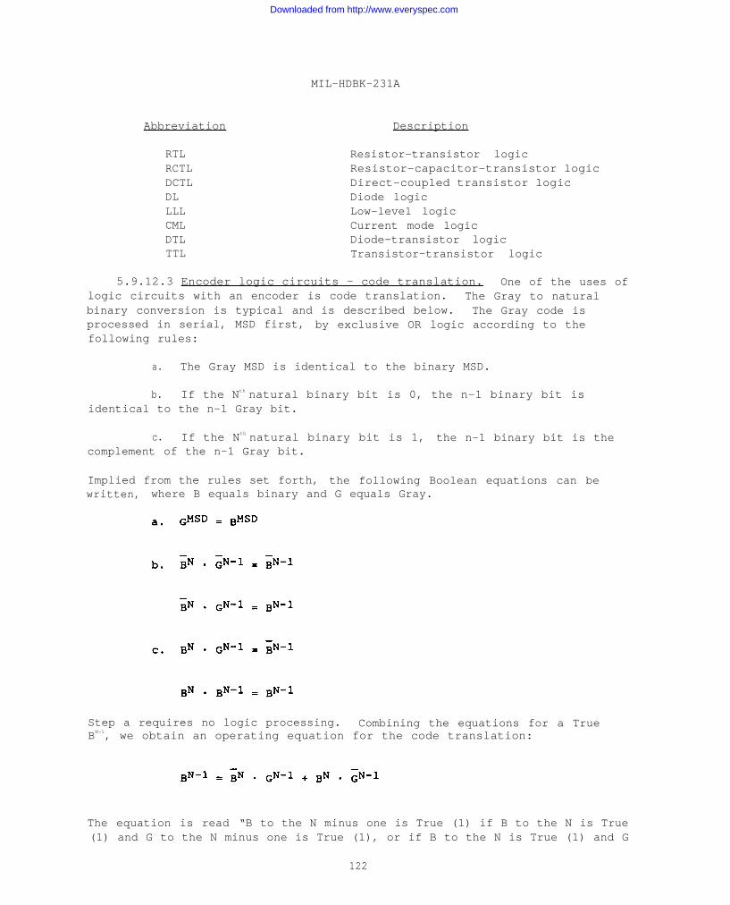
MIL-HDBK-231A
Abbreviation Description
RTLRCTLDCTLDLLLLCMLDTLTTL
Resistor-transistor logicResistor-capacitor-transistor logicDirect-coupled transistor logicDiode logicLow-level logicCurrent mode logicDiode-transistor logicTransistor-transistor logic
5.9.12.3 Encoder logic circuits - code translation. One of the uses oflogic circuits with an encoder is code translation. The Gray to naturalbinary conversion is typical and is described below. The Gray code isprocessed in serial, MSD first, by exclusive OR logic according to thefollowing rules:
a. The Gray MSD is identical to the binary MSD.
b. If the Nth natural binary bit is 0, the n-1 binary bit isidentical to the n-1 Gray bit.
c. If the Nth natural binary bit is 1, the n-1 binary bit is thecomplement of the n-1 Gray bit.
Implied from the rules set forth, the following Boolean equations can bewritten, where B equals binary and G equals Gray.
Step a requires no logic processing. Combining the equations for a TrueBN-1, we obtain an operating equation for the code translation:
The equation is read “B to the N minus one is True (1) if B to the N is True(1) and G to the N minus one is True (1), or if B to the N is True (1) and G
122
Downloaded from http://www.everyspec.com
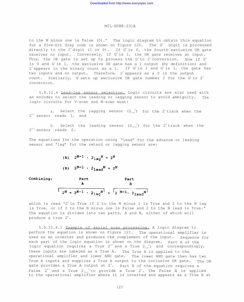
MIL-HDBK-231A
to the N minus one is False (0).” The logic diagram to obtain this equationfor a five-bit Gray code is shown on Figure 120. The GN digit is processeddirectly to the 2N digit (1 or 0). If GN is 0, the fourth exclusive OR gatereceives no input. Conversely, if GN is 1, the OR gate receives an input.Thus, the OR gate is set up to process the G3 to 23 conversion. Now if GN
is 0 and G3 is 1, the exclusive OR gate has a 1 output (by definition) and23 appears in the binary count as a 1. If GN is 1 and G3 is 1, the gate hastwo inputs and no output. Therefore, 23 appears as a 0 in the outputcount. Similarly, G3 sets up exclusive OR gate number 3 for the G2 to 22
conversion.
5.9.12.4 Lead-lag sensor selection. Logic circuits are also used withan encoder to select the leading or lagging sensor to avoid ambiguity. Thelogic circuits for V-scan and M-scan must:
a. Select the lagging sensor (2lag
N) for the 2N track when the2N-1 sensor reads 1, and
b. Select the leading sensor (2lead
N) for the 2N track when the2N-1 sensor reads 0.
The equations for the operation using “lead” for the advance or leadingsensor and “lag” for the retard or lagging sensor are:
which is read "2N is True if 2 to the N minus 1 is True and 2 to the N lagis True, or if 2 to the N minus one is False and 2 to the N lead is True.”The equation is divided into two parts, A and B, either of which willproduce a true 2N.
5.9.12.4.1 Example of serial scan processing. A logic diagram toperform the equation is shown on Figure 121. The operational amplifier isused as an inverter and produces the complement of the input. Sequence foreach part of the logic equation is shown on the diagram. Part A of thelogic equation requires a True 2N-1 and a True 2lag
N; and correspondingly,these inputs are labeled as a True A. The True A is applied to theoperational amplifier and lower AND gate. The lower AND gate then has twoTrue A inputs and supplies a True A output to the inclusive OR gate. The ORgate provides a True A output at 2N. Part B of the equation requires aFalse 2N-1 and a True 2lead
N to provide a True 2N. The False B is appliedto the operational amplifier where it is inverted and appears as a True B at
123
Downloaded from http://www.everyspec.com
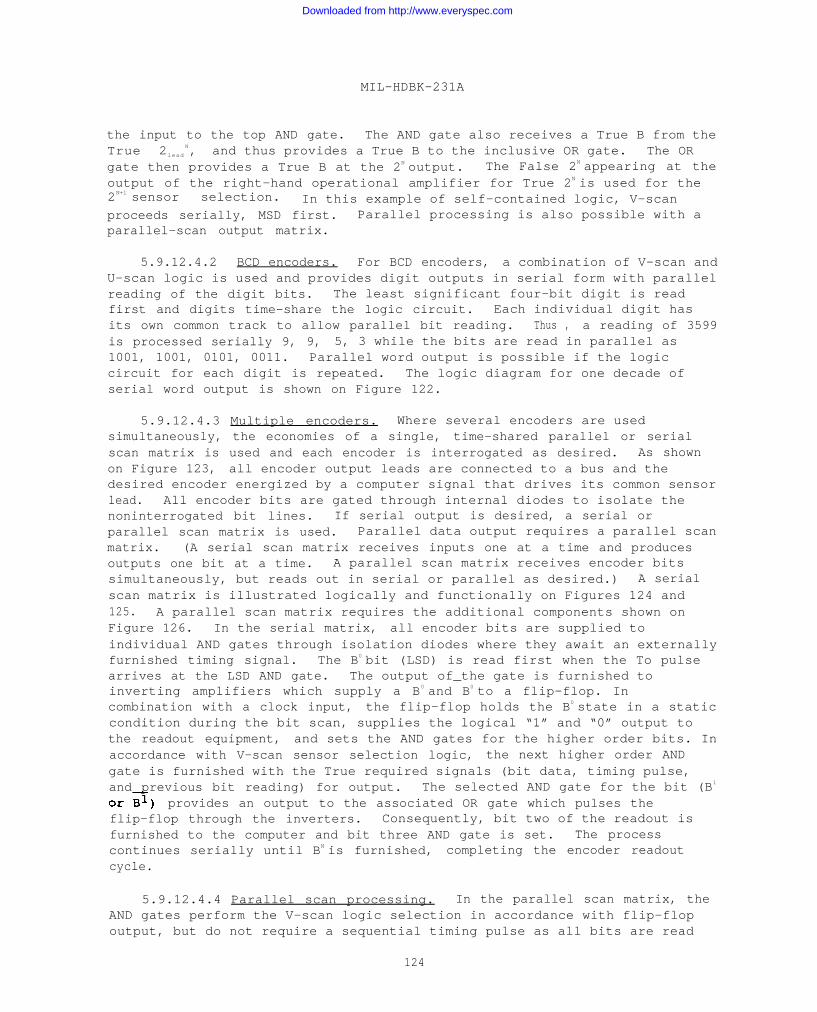
MIL-HDBK-231A
the input to the top AND gate. The AND gate also receives a True B from theTrue 2lead
N, and thus provides a True B to the inclusive OR gate. The ORgate then provides a True B at the 2N output. The False 2N appearing at theoutput of the right-hand operational amplifier for True 2N is used for the2N+1 sensor selection. In this example of self-contained logic, V-scanproceeds serially, MSD first. Parallel processing is also possible with aparallel-scan output matrix.
5.9.12.4.2 BCD encoders. For BCD encoders, a combination of V-scan andU-scan logic is used and provides digit outputs in serial form with parallelreading of the digit bits. The least significant four-bit digit is readfirst and digits time-share the logic circuit. Each individual digit hasits own common track to allow parallel bit reading. Thus , a reading of 3599is processed serially 9, 9, 5, 3 while the bits are read in parallel as1001, 1001, 0101, 0011. Parallel word output is possible if the logiccircuit for each digit is repeated. The logic diagram for one decade ofserial word output is shown on Figure 122.
5.9.12.4.3 Multiple encoders. Where several encoders are usedsimultaneously, the economies of a single, time-shared parallel or serialscan matrix is used and each encoder is interrogated as desired. As shownon Figure 123, all encoder output leads are connected to a bus and thedesired encoder energized by a computer signal that drives its common sensorlead. All encoder bits are gated through internal diodes to isolate thenoninterrogated bit lines. If serial output is desired, a serial orparallel scan matrix is used. Parallel data output requires a parallel scanmatrix. (A serial scan matrix receives inputs one at a time and producesoutputs one bit at a time. A parallel scan matrix receives encoder bitssimultaneously, but reads out in serial or parallel as desired.) A serialscan matrix is illustrated logically and functionally on Figures 124 and125. A parallel scan matrix requires the additional components shown onFigure 126. In the serial matrix, all encoder bits are supplied toindividual AND gates through isolation diodes where they await an externallyfurnished timing signal. The B0 bit (LSD) is read first when the To pulsearrives at the LSD AND gate. The output of_the gate is furnished toinverting amplifiers which supply a B0 and B0 to a flip-flop. Incombination with a clock input, the flip-flop holds the B0 state in a staticcondition during the bit scan, supplies the logical “1” and “0” output tothe readout equipment, and sets the AND gates for the higher order bits. Inaccordance with V-scan sensor selection logic, the next higher order ANDgate is furnished with the True required signals (bit data, timing pulse,and previous bit reading) for output. The selected AND gate for the bit (B1
provides an output to the associated OR gate which pulses theflip-flop through the inverters. Consequently, bit two of the readout isfurnished to the computer and bit three AND gate is set. The processcontinues serially until BN is furnished, completing the encoder readoutcycle.
5.9.12.4.4 Parallel scan processing. In the parallel scan matrix, theAND gates perform the V-scan logic selection in accordance with flip-flopoutput, but do not require a sequential timing pulse as all bits are read
124
Downloaded from http://www.everyspec.com
MIL-HDBK-231A
simultaneously. When both bit and flip-flop output are presentsimultaneously, the selected AND gate provides an output via the OR gate tothe following inverting amplifiers which generate bit and complement for thereadout equipment. As in a serial scan matrix, the flip-flop stores (holds)the B0 readout state until the bit scan is complete. Since one clock timeis usually used to set the flip-flop, a total of two bit times is requiredfor a single readout. In any case, the logic equations previously statedfor V-scan sensor selection determine flip-flop operation.
5.9.12.5 Direction sensing logic. Direction sensing logic is toindicate the direction of shaft rotation. It usually requires additionalsensors, disc tracks, or both. In incremental encoders, direction sensingmay be accomplished by placing a second sensor on the LSB track located inquadrature (90 degrees) from the initial sensor. The differentiated outputof the initial sensor occurring at the leading and trailing edge of thelogical "1"-“0” transitions then bears a specific relationship to the normaloutput of the direction sensor. This relationship may be expressed by thefollowing logic equations which differ as shaft rotation changes:
The relationship of these pulses is shown in Figure 127. A logic circuit toperform the required logic is shown in Figure 128.
5.9.12.6 Set-Reset logic. Set-Reset logic is used in an encoder toimprove signal-to-noise ratio by reverting a readout to the previous readingif noise error exists. Encoder construction requires two LSB tracks andsensors, such that the sensors are alternately “On” and “Off”, but withoverlap. Normally, the 2° track is defined as the Set track and 2° as theReset track. Detection of the 2° state is made through latch techniques andis held until Reset. An associated selector circuit operates in accordancewith the truth table shown in Table XL (for the Set-Reset definitions andtrack assignment discussed). As shown, the present output is independent ofthe previous value except when both Set and Reset are a logical “0”, inwhich case the present output equals the previous output. A basic logiccircuit to perform the criteria set forth in the truth table is shown onFigure 129.
5.10 Applications, tradeoffs, and error.
5.10.1 Applications.
5.10.1.1 Applications - general. One of the most difficult decisionsfacing the system engineer is the design or selection of an encoder suitedto detailed needs and requirements. Often the important systemcharacteristics are determined and fixed far in advance of consideringencoder hardware. If the system development progresses without earlyallowance for the encoding function, the system engineer may be faced with
125
Downloaded from http://www.everyspec.com
MIL-HDBK-231A
solving an encoding problem far beyond the complexity implied by the systemfunction. This disproportionate complexity results from establishing toomuch of the system design before selecting encoder hardware or without atleast considering it. In such cases, undue limitations may eventually haveto be placed upon size, resolution, power consumption, weight, or any numberof other critical encoder design factors. To avoid this problem, theencoding function must be considered early in the system design anddevelopment phase. Encoder requirements must be identified and defined, thepossibilities investigated, and the available options analyzed to yield thebest system solution. The following discussion presents encoder selectioncriteria and provides a general basis for evaluating requirements relativeto specific encoder units.
5.10.1.2 Encoder classes. Encoders, regardless of the manner in whichthey perform the encoding function, can be classified as belonging to one oftwo major families of encoders: incremental or absolute. A firstconsideration will be to decide which family is best-suited to system needs.
5.10.1.2.1 Incremental encoders. The incremental encoder is by far thesimplest since its only requirements are to generate a single signal forequal angular increments of shaft angle. The encoder may also contain azero reference marker. The direction of shaft rotation can be readilydetected through one additional code sensor. Circuitry is simple and powerrequirements modest. High resolutions in minimal size units are possible,particularly in the optical types.
5.10.1.2.1.1 Advantages vs disadvantages. There are advantages to suchan encoder and weaknesses as well. If for any reason power is interruptedto the encoder or a transmission or reception failure occurs, counts will belost . In the encoder without a zero marker, this loss is permanent andresults in an error which will persist until the external counter is resetto zero. In units with zero reference, the error will persist until thereference has been sensed. In addition, some means must be provided foraccumulating the output of the encoder. The required counter may be eitherexternal or internal. It should be noted that in systems using a number ofencoders, time-sharing becomes impossible and every encoder must be equippedwith its own counter. This leads to a considerable increase in cost, bulk,and lower reliability.
5.10.1.2.1.2 Incremental without zero reference. Nevertheless, in manyapplications the incremental encoder represents a nearly ideal solution tothe encoding problem. For example, incremental encoders without zeromarkers are used in many x-y plotters. In this application, the encoder isused in the “floating zero” mode because the counter rather than the encoderdefines the zero point by being cleared and zero-set on command.
5.10.1.2.2 Absolute encoders. The second family, the absoluteencoders, are considerably more complex in construction, since the encoderdelivers not only the smallest increment or bit of shaft angle rotation, buta complete word defining the location of the least bit sensed. Theprincipal advantage of the absolute encoder is that it is in effect its own
126
Downloaded from http://www.everyspec.com

MIL-HDBK-231A
counter, since it sums and simultaneously displays the total number of leastbits from the zero position. The type of code in which this sum isdisplayed can be varied to suit the particular application. The secondimportant advantage of the absolute encoder is that operation is independentof previous events or conditions. A power failure, for example, willprevent encoder output during the failure; but when power is restored, theencoder will again immediately provide the absolute shaft position readout.The absolute encoder is an on-demand component and needs no attention fromthe system until its information is required. This capability of theabsolute encoder gives the designer a powerful tool for reducing complexityin his system by time-sharing the electronic circuits.
5.10.1.2.2.1 Essential electronics. The precise degree of economy thatcan be effected through time-sharing depends on a number of interrelatedfactors. There is a certain amount of electronics essential to an absoluteencoder; circuits that must be used to process data regardless of the typeof parent system or the output requirements. This essential circuitry caneither be included as an internal, integral part of each encoder unit or thecircuitry can be an external element with the output of each encoderconnected sequentially to this circuitry.
5.10.1.2.2.2 Binary contacting encoders. In the case of binary brushencoders, either the self-select type of unit could be chosen which containsall anti-ambiguity selection circuitry within the encoder, or the externallogic type of unit could be used where all logical operations to removeambiguity take place in circuits external to the encoders. In practice, ifless than five to eight encoders are tied into one processor, it will beless costly to use self-select encoders. Beyond five to eight encoders,however, it becomes more economical to use external logic encoders and asingle external logic to which each encoder is connected sequentially.
5.10.1.2.2.3 Non-contacting encoders. In the case of non-contactingencoders, external logic units are at present almost invariably less costlythan internal logic types, principally because the logic is the sameregardless of where it is located; unlike the brush type of encoder whereinternal is different in type from external logic (brush-disc-diode logic asagainst solid-state logic). Rather than compressing non-contacting encoderlogic into each unit, there may be a cost advantage in using external logicwith even one encoder, plus additional savings when two or more encoders useexternal logic. Non-contacting encoders require signal processing circuitsthat are distinct from the logical operations. These processing circuitsare used to interrogate the encoders, amplify low-level signals, detectamplitude modulated encoder outputs, and so on. Often these circuits can beexternal to the encoder and used sequentially for all encoders. Sometimesthe circuits must be in each encoder, for example, to amplify low levelencoder sensor signals before external signal processing is possible.Clearly, for maximum economy, non-contacting encoder designers attempt todevelop either encoders with extremely simple internal circuit requirementsor encoders that produce high-level outputs of a type suitable for externallogical manipulation with minimal internal encoder circuitry.
127
Downloaded from http://www.everyspec.com
MIL-HDBK-231A
5.10.1.2.2.4 Absolute vs. incremental. The advantage of the absoluteencoder, to provide a complete shaft position readout, implies the use ofmany more components and, therefore, greater probabilities of failure thanthe incremental type. An absolute shaft position readout does not of itselfcertify an absolutely correct readout. To ensure accuracy, some means isrequired to detect when the encoder is in error. This in turn requires amethod of comparing the encoder output with some other signal known to becorrect, or else the use of logical manipulations. Unfortunately, a signalknown to be correct is not generally available and logic techniques must beused. The best known of these in the field of contacting encoders is thegeneration of complementary outputs directly from the code disc within theencoder. These complements are then compared with the digit. If both trueand complements are the same for any digit, an error exists. This is anextremely effective method of error detection in brush encoders. Thecomplements checking method, when applied to non-contacting encoders, is notquite as effective because the method of bit sensing and the usualprocessing circuits required make for more possible failure modes,presupposing an electronically generated complement.
5.10.1.3 Resolution. The maximum resolution (counts per turn) of anencoder is essentially limited by the smallest bit that can be reliablydetected by the sensing method chosen and by the attainable angularprecision of the code pattern and the code sensor. Clearly, the greater thediameter of the code pattern, the greater the resolution. The increase inpattern diameter cannot, of course, be extended indefinitely, since there isalways some limit on maximum size and because mechanical tolerance problemsand lowered capacity to withstand extreme environmental conditions willultimately overwhelm the potential count capacity.
5.10.1.3.1 Higher resolution. If higher resolution in a given packageis desired, techniques of sensing smaller bits and increasing the angularaccuracy of the pattern and pattern sensor can be developed and used. Inhigh resolution absolute encoders, the approach that would lend itself bestto high resolution requirements is optical. The tradeoff considerations orpenalties in this situation would include lowered environmental capability,probable lower coding speed, still appreciable bulk, inclusion of circuitryin the encoder, and the absence of a self-check. If the resolution requiredis moderate (10 to 13 bit), it may be possible to use magnetic, capacitive,or inductive types. These are not as likely to be as sensitive toenvironment, can be built for very low inertia or very high-speedapplications, and can be provided with external circuitry.
5.10.1.3.2 Lower resolution. If 10 bit or lower resolutions will do,consideration should be given to contacting types, particularly where lifeexpectancies are not overly long and, very particularly, where cost is amajor factor. As the requirement for high resolution increases without acompensating increase in encoder size, the cost and the likelihood of poorenvironmental resistance will experience a parallel increase.
5.10.1.3.3 Size. Encoders can be built to very high resolutions insmall frame sizes provided it is permissible to generate the full count in
128
Downloaded from http://www.everyspec.com
MIL-HDBK-231A
more than one revolution of the encoder input shaft. For example, a 13-bitbinary absolute encoder can be easily built by ganging a seven-bit frontsection with a six-bit rear section through a 64-to-1 gear reduction. This
unit will turn out a full count in 64 turns of the input shaft. Thisapproach has proved highly satisfactory and is, in fact, one of the most-used techniques for attaining higher resolutions, particularly in systemsutilizing two-speed servo systems.
5.10.1.4 Encoder specifications. In specifying encoder performance orin evaluating the parameters specified for existing encoder units, the trulycritical factors must be identified and analyzed. Insignificant
characteristics should be given the widest possible latitude. The followingparameters will usually be critical and will require special carefulconsideration.
5.10.1.4.1 Brush current. Often, in contacting encoders, parameterssuch as brush current are labeled as maximum values. The values shouldnever be exceeded. This is because of the high probability that decreasedencoder lifetime will result.
5.10.1.4.2 Sensor output. One of the most important considerations isthe output current capability of each sensor. Due to the minute size of thesensors used in encoders, considerable heating can take place during evenmomentary overloads. Such heating can cause irreversible changes in theencoder characteristics.
5.10.1.4.3 Line capacitance. Line capacitance must be taken intoaccount when fitting the encoder to the system. In the case of brushencoders, current limiting is provided by series resistances inserted ineach output line. These current-limiting devices should be located as closeto the encoder as possible to prevent surge overloads caused by linecapacitance.
5.10.1.4.4 Line rise times. When line rise times cannot meetspecifications because of current limiting, buffer amplifiers must be used.By programming the encoder “on” at some point in time before it is to beread, the time necessary to set lines with the current limiting can be usedas a means of eliminating the need for buffer amplifiers. Somespecification limitations exist only because necessary testing to verifyperformance has not been accomplished.
5.10.1.4.5 Commutation. Some types of encoders must, by their nature,commutate while other encoders do not. Care must be exercised in theapplication of encoders to be certain that no encoder is forced to commutatewhen it is not designed to do so.
5.10.1.4.6 Specification checklist. System requirements for encodersmust be specified at the earliest possible point in a program or project.This can often make the difference between highly successful encoder/systemintegration and a piecemeal, unsatisfactory patchwork of almost adequatesecond guesses. When properly fitted to the system, encoders provide
129
Downloaded from http://www.everyspec.com
MIL-HDBK-231A
reliable, economic, and flexible transducers in the interface between thecomputer and the operating equipment. The important encoder characteristicsthat must be considered in preparing or evaluating a specification aresummarized in Table XLI.
5.10.2 Tradeoffs.
5.10.2.1 Tradeoffs - general. In selecting or designing encoderhardware, regardless of family, type, or category, certain considerations ofreliability, service life, accuracy, and resolution are basic. Thesefactors must be traded off within the confines of a general design approachto resolve hardware details and derive the exact encoder configurationrequired for a specific task. In the following discussion, each tradeofffactor is presented, evaluated, and its relationship to other factors andoverall encoder capability explained.
5.10.2.2 Maximum life versus reliability. Reliability should not beconfused with maximum life. A statement or requirement of “revolutionslife” is often used as a substitute for more precise specifications definingreliability. There are several reasons why reliability expressed in“revolutions life” is neither sufficient nor correct. First, the concept ofrevolutions life, taken as an isolated characteristic, ignores resolution.For example, an encoder with seven bit per turn (128 counts) resolution mustrun at twice the speed and last for twice as many revolutions as an eight-bit per turn (256 count) encoder for the same output count in a given numberof degrees rotation of the input function. This can easily be seen in theexample shown on Figure 130. For this reason, an eight-bit per turn encoderwith five million revolutions life is more reliable than a seven-bit perturn encoder with 10 million revolutions life. A more accuratespecification for reliability can be stated as the product of the maximumrevolutions life multiplied by the total counts per revolution (resolution).
5.10.2.2.1 Life. When reliability is expressed in “revolutions life”,the error rate or noise level during life and at end of life is notconsidered. Error rate is determined by encoder noise, together with thecharacteristics of associated storage circuits. For a given contact noiselevel, a change in storage circuit design can alter the error rate by afactor of 1,000 or more. Contact materials which produce moderate noise inearly life can have less wear and longer life than materials with much lowernoise levels during early life. Storage circuits which are designed tooperate error-free in the presence of moderate noise can significantlyincrease the life of the system.
5.10.2.2.2 Temperature extremes. Reliability must take intoconsideration temperatures encountered during life. contact noise, contactwear and life are greatly influenced by the surface properties of thecontact materials. These surface conditions are greatly altered by chemicalreactions with lubricants introduced during manufacture, with wear products,and by the surrounding atmosphere. These reactions are profoundlyinfluenced by temperature. At low temperatures lubricants can become highlyviscous. Inversely, at high temperatures lubricants can decompose or react
130
Downloaded from http://www.everyspec.com
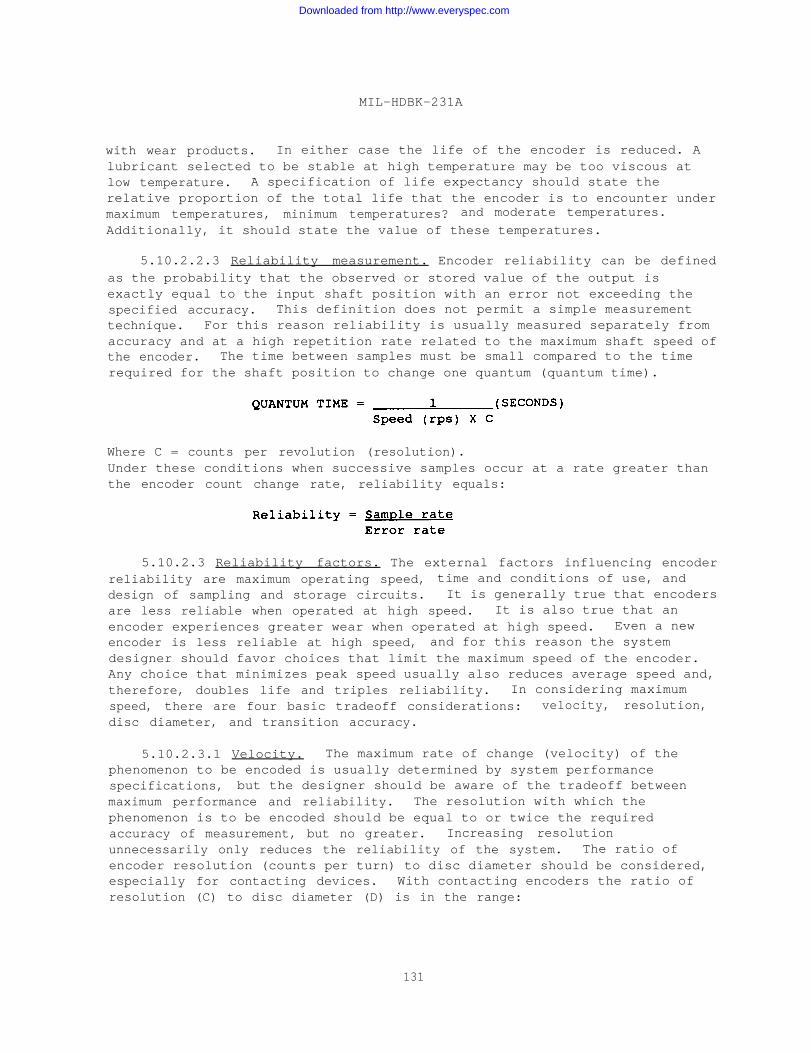
MIL-HDBK-231A
with wear products. In either case the life of the encoder is reduced. Alubricant selected to be stable at high temperature may be too viscous atlow temperature. A specification of life expectancy should state therelative proportion of the total life that the encoder is to encounter undermaximum temperatures, minimum temperatures? and moderate temperatures.
Additionally, it should state the value of these temperatures.
5.10.2.2.3 Reliability measurement. Encoder reliability can be definedas the probability that the observed or stored value of the output isexactly equal to the input shaft position with an error not exceeding thespecified accuracy. This definition does not permit a simple measurementtechnique. For this reason reliability is usually measured separately fromaccuracy and at a high repetition rate related to the maximum shaft speed ofthe encoder. The time between samples must be small compared to the timerequired for the shaft position to change one quantum (quantum time).
Where C = counts per revolution (resolution).Under these conditions when successive samples occur at a rate greater thanthe encoder count change rate, reliability equals:
5.10.2.3 Reliability factors. The external factors influencing encoderreliability are maximum operating speed, time and conditions of use, anddesign of sampling and storage circuits. It is generally true that encodersare less reliable when operated at high speed. It is also true that anencoder experiences greater wear when operated at high speed. Even a newencoder is less reliable at high speed, and for this reason the systemdesigner should favor choices that limit the maximum speed of the encoder.Any choice that minimizes peak speed usually also reduces average speed and,therefore, doubles life and triples reliability. In considering maximumspeed, there are four basic tradeoff considerations: velocity, resolution,disc diameter, and transition accuracy.
5.10.2.3.1 Velocity. The maximum rate of change (velocity) of thephenomenon to be encoded is usually determined by system performancespecifications, but the designer should be aware of the tradeoff betweenmaximum performance and reliability. The resolution with which thephenomenon is to be encoded should be equal to or twice the requiredaccuracy of measurement, but no greater. Increasing resolutionunnecessarily only reduces the reliability of the system. The ratio ofencoder resolution (counts per turn) to disc diameter should be considered,especially for contacting devices. With contacting encoders the ratio ofresolution (C) to disc diameter (D) is in the range:
131
Downloaded from http://www.everyspec.com
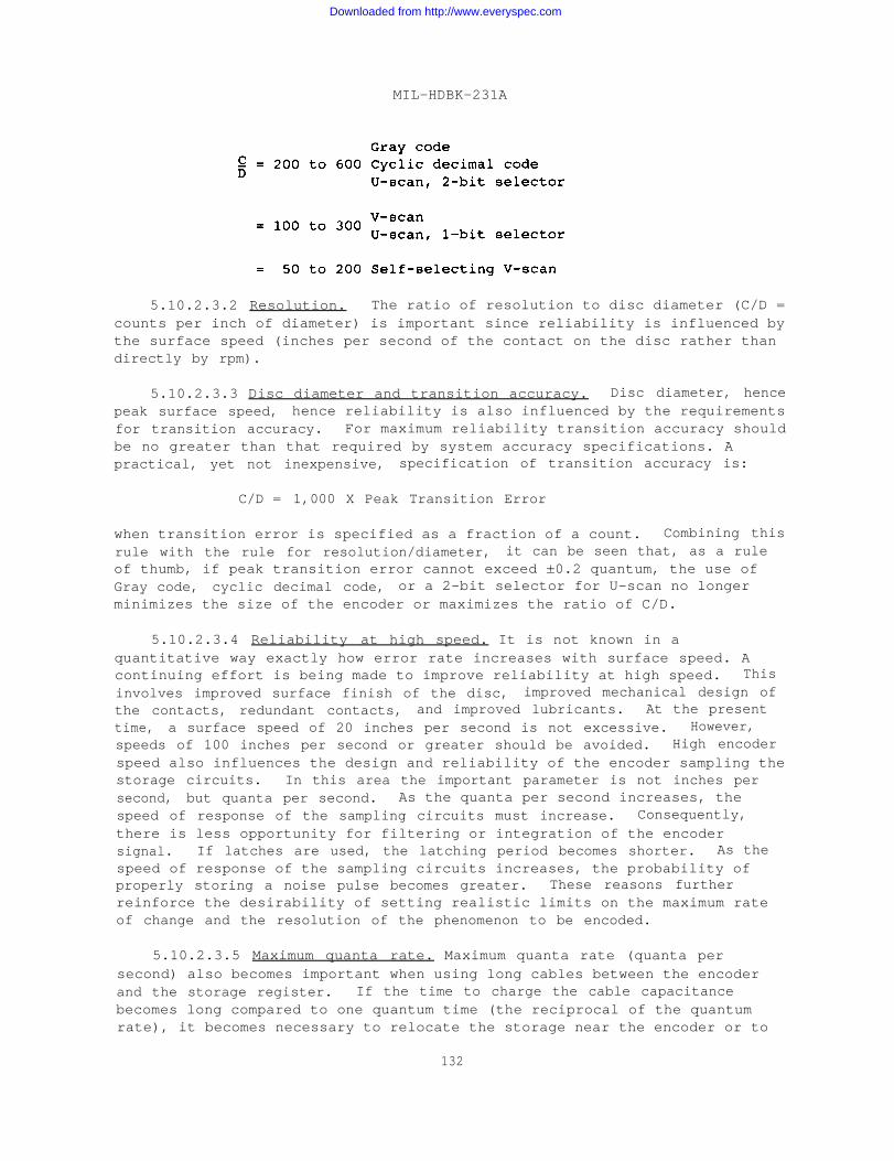
MIL-HDBK-231A
5.10.2.3.2 Resolution. The ratio of resolution to disc diameter (C/D =counts per inch of diameter) is important since reliability is influenced bythe surface speed (inches per second of the contact on the disc rather thandirectly by rpm).
5.10.2.3.3 Disc diameter and transition accuracy. Disc diameter, hencepeak surface speed, hence reliability is also influenced by the requirementsfor transition accuracy. For maximum reliability transition accuracy shouldbe no greater than that required by system accuracy specifications. Apractical, yet not inexpensive, specification of transition accuracy is:
C/D = 1,000 X Peak Transition Error
when transition error is specified as a fraction of a count. Combining thisrule with the rule for resolution/diameter, it can be seen that, as a ruleof thumb, if peak transition error cannot exceed ±0.2 quantum, the use ofGray code, cyclic decimal code, or a 2-bit selector for U-scan no longerminimizes the size of the encoder or maximizes the ratio of C/D.
5.10.2.3.4 Reliability at high speed. It is not known in aquantitative way exactly how error rate increases with surface speed. Acontinuing effort is being made to improve reliability at high speed. This
involves improved surface finish of the disc, improved mechanical design ofthe contacts, redundant contacts, and improved lubricants. At the presenttime, a surface speed of 20 inches per second is not excessive. However,speeds of 100 inches per second or greater should be avoided. High encoderspeed also influences the design and reliability of the encoder sampling thestorage circuits. In this area the important parameter is not inches persecond, but quanta per second. As the quanta per second increases, thespeed of response of the sampling circuits must increase. Consequently,there is less opportunity for filtering or integration of the encodersignal. If latches are used, the latching period becomes shorter. As thespeed of response of the sampling circuits increases, the probability ofproperly storing a noise pulse becomes greater. These reasons furtherreinforce the desirability of setting realistic limits on the maximum rateof change and the resolution of the phenomenon to be encoded.
5.10.2.3.5 Maximum quanta rate. Maximum quanta rate (quanta persecond) also becomes important when using long cables between the encoderand the storage register. If the time to charge the cable capacitancebecomes long compared to one quantum time (the reciprocal of the quantumrate), it becomes necessary to relocate the storage near the encoder or to
132
Downloaded from http://www.everyspec.com
MIL-HDBK-231A
employ a monostrophic code. If a monostrophic code is used, it is onlynecessary that the difference between capacitance charging times within thecable be small compared to the minimum quantum time.
5.10.2.3.6 Encoder wear. Encoder wear also has a profound effect onreliability; and these wear factors, especially in contacting encoders, mustbe carefully considered in the design and selection process. The effective
contact length increases with wear. In a well-designed encoder, thisincrease takes place very slowly after the initial run-in period. Increase
in contact length increases transition error, but does not affectreliability until transition error exceeds one-half quantum or more. This
is seldom a serious problem. As an encoder wears, the contact pressurebecomes less. A new encoder contact is deflected 0.015 inch to 0.040 inch(depending upon design) so that considerable wear can be sustained. Changein deflection is a problem only after many years of service, or if theencoder is manufactured with improper contact deflection when new. As an
encoder wears, the wear particles react with the environment to form a non-conducting “sand” that interferes with contact between the contact and disc.These wear particles produce intermittent noise that is only eliminated asthe particles are caught up and retained by the lubricant in a sort of dikealong the contact path. Periodic cleaning and lubrication reduces theeffect of this type of wear. Recent developments with improved metalsurfaces and improved lubricants show promise of reducing this type of wearto negligible proportions. This type of wear is related to speed and tomaximum and minimum temperature effects on the lubricant.
5.10.2.3.7 Lubricant failure. The most serious form of wear resultsfrom a local failure of the metal surface of the disc and the lubricant. Itusually starts at the edge of a segment on the disc and results in gallingor flaking of the surface of the disc. Relatively large portions of thedisc may be transferred to the brush. The end result is rapid wear andearly failure. This type of wear is initiated by local heating, due to acombination of high speed, rough surface, and failure of the lubricant. Thelubricant can fail from decomposition at high ambient temperature or fromexcessive viscosity at very low ambient temperatures. This type of failurecan be predicted by an analysis of the variability of the error rate duringthe early life of the encoder.
5.10.2.4 Electrical desire factors. The following rules form a basisfor good design of encoder storage and sampling circuits. Althoughcompromises are possible to reduce cost when the ultimate in reliability isnot required or when the encoder operation is at low speed in a favorableenvironment, a review of these guidelines is recommended in any applicationof encoders using sliding contacts.
5.10.2.5 Voltage limits. The voltage across an open encoder contactshould not exceed a maximum of 30 volts and preferably be limited to 3 to 10volts. The upper limit may be exceeded providing U-scan or V-scan circuitsare designed in which static switching elements, not the encoder contacts,make and break the circuits. In this case, the maximum voltage limit is setby the design of the static switching circuit. Minimum supply voltage is
133
Downloaded from http://www.everyspec.com
MIL-HDBK-231A
limited principally by the number of diodes in series in the circuit designchosen, and by the amplitude of externally generated electrical noisepresent in the cabling associated with the encoder and storage circuits.Although encoders are binary devices and are much less susceptible to noisethan analog transducers, nevertheless, reasonable consideration must begiven to noise suppression including such items as the use of twisted pairconductors to avoid magnetic coupling, use of shielding to avoid capacitivecoupling, use of common grounds, and isolation and filtering of power supplysources. Additionally, heavy current pulses in the ground return circuitsmust be avoided.
5.10.2.6 Current limits. Electrical erosion (wear) of contacts isroughly proportional to the energy in the electrical discharge (energy isthe time integral of the product of the instantaneous voltage and current)multiplied by the number of times the current is interrupted. There is,however, a lower limit of energy at which negligible electrical erosiontakes place. This condition results if there is insufficient energy toraise the contact surfaces to a critical temperature, or if most of theenergy is dissipated in the bulk circuit resistance, or both. In any event,electrical erosion is minimized if contact currents are limited to 0.5 to2 mA. Higher currents to 5 mA can be tolerated if the sampling circuits aredesigned so that power is applied to the encoder only when it is sampled andif the sampling interval is less than one percent of the interval betweensamples. If U-scan, V-scan or decimal encoders are used in which staticswitching elements, not the encoder contacts, make and break the current,then the encoder contacts can be designed to carry 100 mA or more at theoutput .
5.10.2.7 Contact resistance. An encoder contact is a binary elementand, therefore, associated circuits are required only to decide whether thecontact is opened or closed. Although encoder contact resistance isnormally less than one ohm, conservative design practice provides a marginfor reduced contact force due to wear, acceleration or vibration and for theseries resistance of associated wiring and cabling. A good rule is todesign the storage or decision-making circuits so that in the worst case anyencoder circuit with a resistance of less than 200 ohms is interpreted as aclosed contact. Similarly, the resistance of an open encoder contact isnormally greater than one megohm; nevertheless, conservative design practicespecifies that in the worst case any encoder circuit with a resistance ofgreater than 5,000 ohms should be interpreted as an open contact.
5.10.2.8 Polarity. There is minor reduction in electrical erosion ifthe disc is made positive with respect to the output brushes. Naturally, ifthis is done, the common contacts are positive with respect to the disc.These contacts do not make or break current and are usually at the insidediameter of the disc and, therefore, usually have less wear than the othercontacts.
5.10.2.9 Sampling circuits. Wear is reduced and reliability isimproved if power is applied to encoder contacts only during interrogation.Sampling circuits designed to this rule also are necessary if outputs from
134
Downloaded from http://www.everyspec.com
MIL-HDBK-231A
two or more encoders are to be connected to a common data bus. Particular
attention should be given to any amplifiers used to energize the lead andlag commons to ensure that both commons are deenergized except during thesampling interval.
5.10.2.10 Capability summary. The results of some reliability testingof state-of-the-art encoders of various types are presented here to providea general basis for comparison and as a capability summary. These test
results are by no means figures of ultimate reliability and merit, andincreased performance can be expected as the results of design andmanufacturing improvements are incorporated into hardware units.
5.10.2.10.1 Contact encoders. Brush encoders have demonstrated theability to run well beyond 7,600,000 turns at 200 rpm, continuouslymonitored for error while being interrogated 5,000 times per second. The
total time required to run 7,500,000 turns in an accelerated test at themaximum encoder speed was 625 hours. Errors occurred on the average about
once in each 16,000,000 interrogations. The mean time between failures
(MTBF) was 16,000,000 turns for a sample of six encoders tested under theseconditions. These encoders were tested for, and are currently used in, firecontrol and navigation systems in U.S. Navy submarines. Other brush
encoders of a different type have been tested on an autocorrelator for arated lifetime of 2,000,000 turns. These encoders were required to operatein a severe environment where a difference of 140 millivolts was the marginbetween good data and errors in the worst case condition. Six encoders in a
particular sample went to a MTBF of approximately 4,000,000 turns under thetest conditions. These encoders were interrogated at a rate of 6,000 timesa second. During the entire test period, stretching over some three months,
the encoders were interrogated at a rate of 6,000 times a second; and theencoders were interrogated without error approximately 850,000,000 times.Pin contact encoders have demonstrated service life and reliabilitycharacteristics equal to, and in some cases better, than that shown forbrush contact types. In addition, the test performance of pin contact unitsindicates superior resistance to environmental ambients (shock, vibration,and so on) and uncommonly high resistance to wear. Most importantly, pincontact encoders maintained extremely high accuracy levels in test sequencesand showed especially good MTBF figures.
5.10.2.10.2 Magnetic encoders. Because of the absence of contactingcomponent elements and the high environmental resistance, magnetic encodersprovide good performance and high reliability. Magnetic encoders, subjectedto life testing following full round of abuse in the environmental testlaboratory, have been observed to operate to 500,000,000 turns with no signof degradation. It is generally agreed that a well-designed and properlybuilt magnetic encoder has a maximum service life limited only by bearinglife. In many life tests of magnetic units, the total course of the testsequence is run without experiencing a unit failure even under extremelyaccelerated conditions.
5.10.2.10.3 Optical encoders. Optical units display much the samedegree of high reliability and longevity experienced with magnetic encoders.
135
Downloaded from http://www.everyspec.com
MIL-HDBK-231A
However, a second factor (aside from bearing life) limits the service lifeof optical encoders, and that factor is the required light source. Themajority of presently available units employ miniature incandescent bulbs.Bulb life expectancy is enhanced by operating them below their rated voltagelevels. Also, all filaments are in series which adds to the stability ofthe array by equalizing current. Nominally, 10,000 hours of lamp life canbe expected with most good quality optical encoders and a bearing life up to10,000 hours even under conditions of continuous operation at high speeds.
5.10.3 Accuracy factors, encoder error, and minimization. Encodersdescribed in this handbook are limited to those which encode a mechanicalshaft position into a digital output. AS such, both contact and non-contact encoders have an input shaft which is rotated in accordance with theanalog input, a method of encoding the analog information in digital form,and output leads and circuitry. Inherent in any measurement technique isthe uncertainty of the results. The following paragraphs deal with both theinherent and other errors in the encoder measurement technique, generalperformance in terms of encoder specifications and terms, and errorcorrection techniques. Total encoder error is composed of quantizationerror, transition error, error due to ambiguity, and noise error. Noiseerror and transition error are closely associated, but are discussedseparately herein as they do not affect accuracy. As previously defined,reliability of an encoder is the probability that the observed or sampledvalue of the output is equal to the input shaft position with an error notexceeding the specified accuracy. This is in contrast to accuracy which isdefined as equal to the sum of quantizing error, which is always less than±0.5 the least count; (one-half minimum quantum); and the transition error,which is the measure of the sum of all errors arising from manufacturingtolerances and wear.
5.10.3.1 Quantization error. Quantization error, or round-off error,is the inherent error induced whenever a continuous, smoothly variablefunction (analog data) is changed by subdivision into data which has afinite number of discrete steps. Thus, in subdividing an analog input intoa specified number of discrete steps, there will be a maximum possibleinherent error of ± one-half the value of the last step. The value of thislast or smallest step in a subdivision expressed in terms of the inputangular increment is called a quantum. Accordingly, the last digit of adigitized analog value is uncertain. Probability laws indicate that anyvalues between the above limits are equally possible and that the standarddeviation sigma is equal to 0.289 times the value of the quantum. Averagequantization error over a given number of readings is one-fourth of aquantum. Quantization error, and hence encoder accuracy, can be reducedonly by increasing the number of subdivisions of the analog data (increasingthe output count or resolution). A practical limit on increases in outputcount based on degradation of reliability is such that the size of a quantumshould allow twice the encoder accuracy required by the system, but no more.Increasing output count is usually obtained at the expense of disc diameterand, therefore, encoder size, disc surface speed, or other life factors.Maximum quanta rate also determines maximum output cable length and designof associated circuitry. Quantizing error is also defined as the inherent
136
Downloaded from http://www.everyspec.com
MIL-HDBK-231A
degradation associated with digitizing an analog shaft position (round-offerror). Quantizing errors may vary from -0.5 to +0.5 minimum quantum with
all intermediate values being equally likely. The standard deviation sigma
of quantizing error is 1/12 quantum. The probable quantizing is one-fourth
that observed in half the samples. Quantizing error is fixed error and canonly be reduced by increasing the resolution of the digital output count.
5.10.3.2 Transition error. Transition error is the measure of allmanufacturing errors or tolerances and wear, and is also known as instrumenterror. Manufacturing and tolerance errors include errors in the master discpattern, plating accuracy of the disc, and concentricity of disc rotation.Concentricity of rotation in turn depends on disc manufacturing accuracy,bearing quality, shaft runout and perpendicularity. Errors due to wear
include bearing wear, brush and disc wear for contact encoders, and gearwear in multi-turn encoders. The sum of these errors is comparable bymeasurement of starting and running torques. Encoders which have comparablyhigh running or starting torques may well have reduced life due to wear.The net result of transition error is that a count transition occurs at ashaft angle different from the theoretical shaft angle. Due to the wearfactor in transition error, it is not necessarily constant throughoutencoder life. Assuming transition errors have a normal Gaussiandistribution but with the peak error limited to three times the standarddeviation, one-half of the errors increase toward a negative count and theother half toward a positive count. Therefore, encoders (especiallydevelopmental models) should be operated for a period of time before a finalencoder accuracy is determined. Thus , encoder accuracy is specified on alife basis. For brush type encoders, peak transitional error may beconsidered:
where C = counts per turn
D = disc diameter (inches)
Transition error is the difference between the theoretically correct angleof the input shaft and the actual measured angle at which the output changesfrom one numerical value to the next. Both the theoretical angle and themeasured angle are referenced to a zero position that is halfway between theupper and lower transitions of the zero code output or a specified referenceposition. Transition errors can be assumed to have normal statisticaldistribution, but with the peak error limited to three times the standarddeviation. As an encoder wears, half the transition angles shift towardzero. These are contacts which come on as the shaft is rotated in thedirection of increasing count. Inversely, the other half of the transitionangles shift away from zero. Most encoders are run-in so that the majorchange in transition angle occurs before calibration. In a well made andproperly lubricated encoder, transition error increases very slowly withlife. Transition errors in an encoder are the sum of:
137
Downloaded from http://www.everyspec.com
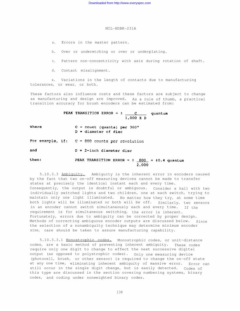
MIL-HDBK-231A
a. Errors in the master pattern.
b. Over or underetching or over or underplating.
c. Pattern non-concentricity with axis during rotation of shaft.
d. Contact misalignment.
e. Variations in the length of contacts due to manufacturingtolerances, or wear, or both.
These factors also influence costs and these factors are subject to changeas manufacturing and design are improved. As a rule of thumb, a practicaltransition accuracy for brush encoders can be estimated from:
5.10.3.3 Ambiguity. Ambiguity is the inherent error in encoders causedby the fact that two on-off measuring devices cannot be made to transferstates at precisely the identical instant each and every time.Consequently, the output is doubtful or ambiguous. Consider a hall with twoindividually switched lights and two children, one at each switch, trying tomaintain only one light illuminated. No matter how they try, at some timeboth lights will be illuminated or both will be off. Similarly, two sensorsin an encoder cannot switch simultaneously each and every time. If therequirement is for simultaneous switching, the error is inherent.Fortunately, errors due to ambiguity can be corrected by proper design.Methods of correcting ambiguous encoder outputs are discussed below. Sincethe selection of a nonambiguity technique may determine minimum encodersize, care should be taken to assure manufacturing capability.
5.10.3.3.1 Monostrophic codes. Monostrophic codes, or unit-distancecodes, are a basic method of preventing inherent ambiguity. These codesrequire only one digit to change to effect the next successive digitaloutput (as opposed to polystrophic codes). Only one measuring device(photocell, brush, or other sensor) is required to change the on-off stateat any one time, eliminating inherent ambiguity of massive error. Error canstill occur in the single digit change, but is easily detected. Codes ofthis type are discussed in the section covering numbering systems, binarycodes, and coding under nonweighted binary codes.
138
Downloaded from http://www.everyspec.com
MIL-HDBK-231A
5.10.3.3.2 Window code. A window code is a code which prevents any
encoder readout during the transition between numbers. ambiguous outputsare prevented by restriction of the readout time. window codes are a formof detent and are usually electrical. Thus, by adding a window track to a
coded disc and requiring that the window output be “on” before any data isread, transition time is electrically eliminated from the readout. Atypical contact-type coded disc utilizing window code is shown onFigure 51. The outermost track of the disc is the window.
5.10.3.3.3 Lead-lag techniques. The lead-lag (advance-retard)
techniques are methods of prohibiting transition point ambiguity of apolystrophic code by using spaced brushes or sensors, and possiblyadditional tracks, for each digit. Output is taken from either sensor for a
given digit as selected by logic circuits or as keyed by encoder output.
The brushes or sensors are electrically or physically spaced at one-half thetotal minimum bit width. The sensor selected for readout is at least one-half the minimum width away from a transition point, eliminating ambiguity.For optical encoders, a disc mask can be used to perform the lead-lagselection. Many different lead-lag techniques exist. All requireadditional circuitry, either inside the encoder, in the form of external
logic, or more strict manufacturing tolerances for the coded disc. Choice
of a specific technique is a tradeoff and must be interpreted in terms ofsystem requirements and accuracies.
5.10.3.3.4 V-scan. The V-scan technique is a method of obtainingnonambiguous outputs from a polystrophic encoder by utilizing two sensorsfor each bit of disc information except the LSD. This method is named fromthe V-like pattern of the staggered sensors as shown on Figure 131.Selection of the proper sensor for readout of a given bit is determined bylogic circuits which sample the state of the previous LSD. If the logic
determines that the previous LSD was a logical “0”, the leading sensor forthe given bit is selected for readout. Conversely, if a logical “1” existed
in the previous digit, the lagging sensor for the given digit is selectedfor readout. Therefore, the V-scan technique normally proceeds serially,
LSD first. The term leading or lagging is determined by the position of thebrush relative to the reading line and the relative direction of shaftmotion. Changing the direction of encoder rotation also changes the sensorterminology. The reading line, which is the position of the LSD sensor, isthe actual shaft position being read. The V-scan technique can also beaccomplished by modification of the disc (V-disc). In the V-disc
modification (Figure 132), the sensors are operated in line with the disctracks staggered. In-line operation for contact encoders allows a stronger,more durable brush assembly. Logic equations and diagrams for the V-scantechnique are included in another portion of this handbook. A typical
contact-type disc for the V-scan technique is shown on Figure 133.
5.10.3.3.5 Self-selecting V-scan. The self-selecting V-scan technique
is used where lead-lag sensor selection must be performed within an encoderdue to external scan matrix limitations or nonavailability. Self-selection
of the proper sensors for a given disc track is accomplished by placingsensors in series, generating NOT logic functions, and using the previousLSD track data to key the given track. These logic relationships are
139
Downloaded from http://www.everyspec.com

MIL-HDBK-231A
discussed elsewhere in this handbook. Self-selecting V-scan generates bothbit and complement simultaneously as in the external scan matrix, butaccomplishes the logic selection by using four sensors, three tracks, twodiodes, and relatively high power supply voltages. To minimize the totalnumber of tracks, self-selecting V-scan encoders utilize staggered sensorarrangement such that a single track can provide both the lead and lagfunctions.
5.10.3.3.6 M-scan. The M-scan technique is a variation of the V-scantechnique and is used in applications where processing equipment can moreeasily process complements of the V-scan logical output. By obtaining acomplemented output directly from the code disc, the additional circuitryrequired for complementation of V-scan output is eliminated. The M-scanfeature is obtained by defining the normal lag brushes as a NOT function.As in V-scan techniques, M-scan can be accomplished by the M-sensorconfiguration or by in-line sensors and an M-disc. An M-disc is shown onFigure 57 with the track assignment.
5.10.3.3.7 U-scan. The U-scan technique is a lead-lag technique forobtaining nonambiguous outputs that allows a reduction in angularmanufacturing tolerances of the disc tracks. U-scan is usable with allcodes and number systems, but differs from other lead-lag techniques in thatthe LSD is used to select a group of MSD’s rather than only the next MSD.In this manner, the normally required complement generation for advancedtracks is eliminated. In particular, U-scan or equivalents must be used forBCD codes as V-scan cannot be used exclusively. A typical U-scan disc isshown on Figures 134 and 135. Note that tolerances for the higher ordertracks, those most normally critical as the diameter is small, are reducedsince they are not effectively energized until the LSD is present.Additionally, no restriction is placed on track location for a particulardigit. The lead or advance sensors and tracks are of one group and the lagor retard sensors and tracks are a second group. Figure 136 shows the U-scan technique using two groupings to increase manufacturing tolerances.The groups are referred to as belts, with the alpha or selector belt nearestthe edge of the disc and the beta belt near the disc axis. Manufacturingtolerances on the second belt vary with the number of first belt bits usedin the codes. (Bits used for selection but not part of the code reduceresolution and manufacturing tolerances by one-half. ) By using two bits onthe first belt, tolerance is increased by four. Similarly, three alpha beltbits give a tolerance reduction of eight. U-scan is particularly useful ina multi-turn encoder where, by selecting the slow disc bits from the fastdisc, gear backlash errors are eliminated.
5.10.3.3.8 Combination and other scan techniques. Combinationtechniques and variations of the lead-lag antiambiguity techniques are used.In multi-turn units, a window code may be used on the high-speed disc andU-scan on the low-speed disc. L-scan or T-scan are also available. For BCDencoders, a combination of U-scan and V-scan is used. The selector bit maybe the LSD or generated from a separate track. Ninety degree phased discsmay be used in multi-turn units. In this case, the external computingcircuits compare the overlapping bits to determine which disc to read.Intermediate motion gearing is possible on multi-turn monostrophic encoders.
140
Downloaded from http://www.everyspec.com
The net result of all ambiguity techniques is an encoder output free fromerrors due to code selection.
MIL-HDBK-231A
5.10.3.4 Noise error. Noise error occurs in contact-type encoders andis the error caused by any variation in the steady state resistance of anencoder contact. Most noise error is edge noise occurring at transitionpoints as a sensor switches from “On” to “Off’* or “Off” to “On”, althoughdropouts in the center portion occur also (but at a ratio of 1,000 to 1).Since encoders have current flow only during “On” conditions, the “True” or“1” signals are noisy. Noise error is the sum of contact wear (a form oftransition error), encoder design in terms of materials or lubrication, andoperating conditions such as reading voltage and current. Error rate is thefrequency of errors appearing in the output due to both encoder error andstorage or readout errors. By proper design of both encoder and readoutcircuits, any errors due to noise can be minimized to insignificantproportions for most applications. Some design factors are discussed asfollows.
5.10.3.4.1 Electrical considerations. Contact-type encoders requireconsideration of reading voltage, current, load characteristics, andpolarity. In all cases contact voltage should be restricted to the minimumrequired for readout (overcoming forward resistance of diodes). Voltagesbetween 3 and 10 volts are preferred, and not more than 30 volts for allencoders that utilize the contacts for actual conduction. With lead-lagambiguity circuits having static switching elements, the voltage is limitedby the switching element characteristics. For direct readout, currentthrough encoder contacts should be less than 5 mA, preferably between 0.5and 2 mA. If sampling techniques are utilized, contact currents can exceed100 mA. This is due to the fact that contact wear is an energy-timefunction, not current. Higher currents for shorter durations at the samevoltage yield a similar energy transfer (similar area under the instantvoltage-current-time integral). At the lower values of current, contactsurface temperature is below that at which erosion of contacts becomes aconsideration. Contact wear, electrically, is related to total volt-amperes being switched. Low voltages and low currents below the erosionthreshold are, therefore, essential to long life. If sampling techniquesare to be utilized because of high volt-ampere requirements, designers mustconsider minimum storage time and charging requirements of output cables.If no error is to be permitted in monostrophic codes, sampling times must beless than one-fourth quantum time for systems not utilizing storage. Ifstorage is used, response time must be less than the minimum quantum timefor a no-error output. With polystrophic codes, antiambiguity logic andstorage sampling time must be much less than one-half minimum quantum time.Otherwise, the change from lead-to-lag brush readings would e read intostorage. Loads into which contacts discharge energy should be resistive.Extreme inductive or capacitive loads can reduce contact life to zero. Aspresented in other texts, common circuits (disc) should be of positivepolarity to minimize contact erosion. Since all sensor-disc surfaces have acontact resistance, external circuit design should register True for contactresistances of 100 to 200 ohms or less and False for contact resistances of5,000 ohms or greater. Closed circuits normally measure 0.1 ohm or less ofcontact resistance while open contacts are at least 1 megohm. Thus
141
Downloaded from http://www.everyspec.com

MIL-HDBK-231A
conservative design of external circuits allows a margin of 10,000 (minimum)in the event of erosion and increased or decreased contact resistance.
5.10.3.4.2 Encoder signal-to-noise ratio. As in communications fields,receptors should have a bandwidth slightly less than the informationreceived; no more, no less. A greater bandwidth allows more noise; a lesserbandwidth allows loss of information. Since encoder signals are arelatively low frequency signal, good use can be made from clipping andfiltering techniques. As with other systems, bandwidth is limited by thehighest frequency component required to pass onto ensuing circuits. Forencoders, this is the minimum quantum time or sampling time, whichever isless. Signal-to-noise ratio is important in non-contact encoders, as wellas in contact encoders. For magnetic units, ratios of 30 dB can be obtainedunder ideal conditions. For production units with several tracks, ratiosbetween 15 and 24 dB are typical. Accurate determination of signal-to-noise ratio precludes specific definitions of logical “1’s” and “0’s” uponwhich the ratio is based. Similarly, optical encoders also have a signal-to-noise ratio. When the ratio drops below 10 dB, readout becomes marginalfor accurate detection purposes. Low signal-to-noise ratios in opticalencoders are caused by excessive disc-to-sensor spacings, light diffraction,high reverse current conditions in photo cells or sensors, lowilluminations, or difficult resolution requirements. Poor ratios become afunction of encoder resolution with powers of two beyond the thirteenth, butwith satisfactory encoders being produced above 218. For greaterresolutions, electronic derivation of the LSD’s can be used. Techniques inuse are Beamscan, Phasescan, and digital phase-locked loop techniques.
5.10.3.5 Reliability checking. Encoder reliability is defined as theprobability that encoder output is equal to the mechanical input within thespecified encoder accuracy. Reliability takes into account the auxiliarycircuits used with the basic encoder for all environments and ratedconditions, while accuracy specifies characteristics of the encoder itself.Reliability is usually checked by sampling encoder output many times duringa single quantum time, where a quantum time is the time required for theinput shaft to change one count.
Reliability in general is affected by encoder speed, resolution, discdiameter, LSD segment length, environmental conditions, and design of outputcircuits. Methods of increasing reliability are discussed in the followingparagraphs.
5.10.3.5.1 Latch techniques. The latch technique is a method ofreducing contact-type encoder error by eliminating dropouts during encoder“On” time. Two control signals, a filter, an AND gate, and an OR gate are
142
Downloaded from http://www.everyspec.com
MIL-HDBK-231A
required for each encoder digit so protected, the logic for which isdescribed in the logic section of this handbook. Basically, a controlsignal clears all logic circuits where they await a first indication of a“True” signal. When a logical “1” appears, it is passed to the outputthrough a one-fourth quantum filter. The signal on the output is fed backto the input where it maintains the logic circuit in a True conditiondespite any variation in encoder contact resistance. Latch circuits areused with only momentarily noisy encoders, as the filter cannot discriminatebetween noise and signal. Latch circuits used with noisy encoders actuallydecrease reliability and accuracy.
5.10.3.5.2 Clipping and filtering. As shown on Figure 137, anidealized contact encoder signal typically has edge noise, and may have apartial dropout in the main portion of “On” time. Through the use of aresistance-capacitance filter, areas under the curve are partiallyintegrated, raising the edge noise and fallout toward more positive levels.The filter raises the average component so that a following clipper can havea higher output level for the same input signal. Filters typically have afast rise time to “True” signals, and a relatively slow discharge time to“False” signals. Depending on the maximum information rate, a critical timeconstant is derived. This constant is nominally one-half the samplinginterval if used, or between 0.1 and 0.3 of the minimum quantum time. Risetime response to “True” or “1” signals is then set at approximately 0.025 ofthis time constant and the fall time at 0.250 of the time constant. Itshould be noted that if excessive noise is present in the encoder output,filtering and clipping serve no useful purpose as they operate because ofthe ratio of peak-to-average signal levels and actually do not discriminatebetween noise and signal, except by the varying repetition rates relative toaverage rate or charge.
5.10.3.5.3 Sampling techniques. Sampling techniques are methods ofincreasing encoder reliability by restriction of interrogation rate or time,and by limiting sensor power to actual interrogation time. Interrogation iscontrolled by a sampling pulse to obtain a readout. Sampling is required inmultiple encoder time-shared systems and may be desirable in contact-typeencoder systems. Selection of sampling pulse lengths (widths) may determinethe characteristics of other reliability increasing techniques. When usedin combination with clipper-filter techniques and the sampling pulse isshort compared to a quantum time, the minimum rise time of the filter isgoverned by the sample pulse width. If a long rise time filter is desiredwhile using short length sampling pulses, an additional, continuouslyenergized, low-power selector bit may be incorporated in the encoder.Selection of a sampling technique must be based on the sampling time-quantum time ratio, the code in use, encoder speed, error rate allowable,ambiguity technique in use, and system cable capacitances. Withmonostrophic codes, maximum allowable delay due to charging of cablecapacitances must not exceed one-fourth quantum time or accuracy will not bemaintained. Excess cable capacitance in system will require storageregisters to obtain workable systems. With polystrophic codes and withambiguity techniques, manufacturing tolerances on minimum quantum widths arereduced and thus place additional time restrictions on contemplated storage.Additionally, the selector bit must be stored first to avoid reading the
143
Downloaded from http://www.everyspec.com
MIL-HDBK-231A
wrong combination of lead-lag sensors into storage, and effective cablecapacitance is increased as more than one bit changes for a given adjacentreadout. Accordingly, time requirements for storage in polystrophicencoders are less, and the time required to store the first two leastsignificant bits (LSB’s) must be less than one-half the minimum quantumtime. Sequential storage for V-scan techniques is required unless both leadand lag sensors are stored.
5.10.3.5.4 Set-Reset technique. Set-Reset techniques (logic) may beused to increase encoder signal-to-noise ratio and hence reliability. Set-Reset logic operates on the principle that if an encoder output is noisy,readout reverts to the previous readout until the noisy sensor has beencleared. Two overlapping sensors on the LSB track generate the necessarydata. Logic circuits for Set-Reset logic are covered in other portions ofthis handbook.
5.11 Selection of an encoder.
5.11.1 Encoder characteristics - general. The selection of an encoderor encoder characteristics to perform a given task may become a problem inthat trade-offs must be made. A minimum of items below must be consideredto assure logical selection of a unit. To act as a guide, probablelimitations in selection imposed by the state of the art are shown inTable XLII. Encoders actually produced may differ considerably from thestate-of-the-art units due to development and new manufacturing techniques.Not only should the tables be consulted in selecting an encoder, butmanufacturers should be contacted also. The following criteria is necessaryto specify encoders:
a. Output notation.
b. Output code.
c. Antiambiguity logic.
d. Physical limitations.
e. Electrical requirements.
f. General characteristics.
5.11.1.2 Selecting output notation. The output notation required maywell determine the output code to be used. Any desired output notation canbe coded, and in some cases, new codes must be created to obtain amonostrophic code or a code that is easily complemented. Output notationmay be linear, square root functions, trigonometric, nonlinear, or random.
5.11.1.3 Selecting output code. Output codes are regularly weighted,non-weighted, or arbitrarily weighted. Within the regularly weighted group,natural binary, incremental, BCD codes, and others may be chosen. Naturalbinary is the most compact code and utilizes all possible code combinationsfor the digits available. Incremental code is easily reset to zero and has
144
Downloaded from http://www.everyspec.com
MIL-HDBK-231A
very small torque requirements. The code is useful for rate information.
The BCD is very easy to process. It is comparable to the decimal system and
is ideal for error checking and correction. Using these codes, heavy
current loads can be driven and arithmetic operations performed easily.Encoders using these codes can be operated in parallel with a minimum ofadditional circuitry. However, power consumption is high; circuits are morecomplex; and torque and inertia requirements are higher due to additional
brushes or sensors. Additionally, storage time, physical size, or storageis increased. Cable capacity requirements become more stringent if parallelreadout is required as more than one line must be energized in going to anysuccessive number. These codes are polystrophic. As such, they require
antiambiguity logic, a further increase in torque requirements. As a result
of some types of antiambiguity logic, readout is restricted to serial
operation unless two storage registers are used. If sampling techniques are
used, sampling time is restricted by lead-lag brush techniques. In the
nonweighted group, cyclic or reflected cyclic codes exist which aremonostrophic. These codes are nonambiguous by definition and have highresolution. In multi-turn encoders, high resolution allows a reduction ingear ratios reducing gear backlash problems. Disc size, with the consequent
reduction in inertia and torque requirements is also affected. As disc
size reduces, brush surface travel reduces, increasing contact life for any
given disc speed. With monostrophic codes, bits may be stored in parallel,
simultaneously, without the added storage required by polystrohpic codes andstored at a faster rate. Cable capacity considerations are lessened as onlyone bit changes for each successive number. On the other hand, monostrophic
codes require additional circuitry for arithmetic operations and must carryfull load current across the contacts. Sampling circuits may be required to
increase encoder life. In either group, error checking codes can be
assigned. Where addition, comparison, or storage is not required (such asdirect printouts or typewriters), the direct decimal code, or an almost
equally effective biquinary decimal or alphanumerical code, may be chosen atan increase in size and cable requirements. If comparison or arithmetic
computations are required, external computing circuits work best with abinary coded decimal code. In special applications such as negative-positive readouts or for simplification of antiambiguity logic, combinationcodes can be chosen such as the ICAO (formerly MOA-Gillham) code which is acombination of two cyclic codes. In short, code selection is a trade off
and must be examined in terms of the entire system.
5.11.1.4 Selecting antiambiquity logic. If a polystrophic code is
required, some form of antiambiguity logic must be chosen. Since
antiambiguity logic requires more sensors and more tracks on the coded disc
and varies with the logic chosen, encoder size may be adversely affected by
an improper choice. By proper choice of antiambiguity logic, the extrafunctions required can be minimized in the encoder and transferred toexternal circuits. Alternately, if readout equipment exists, the extrafunctions can be transferred to the encoder, but will probably cause anincrease in encoder size.
5.11.1.5 Selecting physical limitations. Physical limitations include
maximum weight, case length, case diameter, shaft diameter, shaft length,shaft type, and environment.
145
Downloaded from http://www.everyspec.com
MIL-HDBK-231A
5.11.1.5.1 Encoder size. In general, encoder size is determined by thecode used, total output counts required, resolution, and transitionaccuracy. Synchro-type mounts have proved successful and a series ofstandardized synchro mounts are illustrated on Figures 33 through 40.
5.11.1.5.2 Special operating environment. Special operatingenvironments must be specified. Encoder performance is affected byvibration, shock, corrosive atmosphere, temperature, or humidity. Vibrationlevels should be specified in terms of rate (cycles per second) anddirection relative to the encoder axis. Similarly, the maximum shock shouldbe specified in G's. Temperature specifications should be designated by arange of operating temperatures, including storage, as this affectslubricants used, as well as both starting and running torques. Where acombination of environmental conditions such as low temperature andvibration exist simultaneously, they should be so specified if asatisfactory encoder is to be obtained. Adverse environments as they affectencoder bearings are discussed in the following paragraphs.
5.11.1.5.2.1 High temperature. High temperature encoder environmentabove 350°F creates special problems with bearing life as initiallubrication (normally oil) quickly loses its lubricating value (actuallyvaporizes) . A special lubricant must be used, or the former lubricantcontinuously supplied in order to have reasonable encoder life. Limitationsfor available bearing materials are shown in Table XLIII to aid in encodersystem design.
5.11.1.5.2.2 High vacuum. High vacuum encoder environment is similarto high temperature operation in that lubricants vaporize rapidly causing ahigh rate of adhesive wear. Encoder bearings for this application should beof the shielded type which may reduce internal pressures by a power of 100.Various problems and solutions for this type of environment are listed inTable XLIV.
5.11.1.5.2.3 Nuclear radiation. Nuclear radiation environments affectall organic lubricants, which appears as an increase in viscosity and aconsequent increase in torque. Levels at which lubricant usefulness isdestroyed varies with the lubricant as indicated in Table XLV. Althoughencoder bearing materials will operate in radiation environments of greaterthan 108 roentgens, no lubricants are currently available. A radiationenvironment also destroys encoder diodes.
5.11.1.5.2.4 Extreme low temperature. Low temperature encoderenvironment below -100°F again poses lubrication problems. Bearing loadsmust be reduced to absolute minimums, and should be operated in a glass-filled teflon retainer submerged in liquid hydrogen or nitrogen. Bearingmaterials are otherwise satisfactory as they become stronger with lowertemperatures (slowing of molecular action). Table XLVI indicates aselection of lubricants for medium temperature operation.
5.11.1.6 Selecting electrical requirements. The following electricalrequirements should be considered in selecting an encoder. (See 5.6.4.)
146
Downloaded from http://www.everyspec.com

MIL-HDBK-231A
a.
b.
c.
d.
e.
f.
9“
h.storage, and
5.11.1.7
Maximum load voltage per digit.
Maximum load current digit.
Load impedance in ohms and reactive components.
Output signal polarity.
Diode location, external or internal.
Readout method (serial, parallel, or both).
Output connections.
Auxiliary circuits required and location (filter, buffer,so on).
Selecting general characteristics. General characteristics
are usually determined by system requirements or existing situations, andthe following must not be overlooked.
a. Life in revolutions at a specific temperature and speed.
b. Maximum reading speed in rpm.
c. Maximum slewing speed in rpm.
d. Transition accuracy.
5.11.1.7.1 Count characteristics and torque requirements. With thecode and the majority of mechanical input characteristics determined, thefollowing items should be considered:
a. Sense of rotation for increasing counts.
b. Number of total counts for full-scale output.
c. Amount or number of rotations for full count (single-turn ormulti-turn encoder, as applicable).
d. Maximum starting and running torques within mechanical inputlimitations.
e. Maximum moment of inertia within limitations.
5.11.2 Selection of encoders for military use.
5.11.2.1 Specifications. Encoders for military use are described by
two types of specifications, the general specification and the specificationsheet. The general specification sets forth the requirements for allencoders of a specific type or classification, and the specification sheet
147
Downloaded from http://www.everyspec.com
MIL-HDBK-231A
further defines a specific encoder of the general class by statingindividual requirements or by taking exception to the general specification.Specifications may be fully coordinated and used by all branches of themilitary or limited-coordinated and used by as few as one group of aparticular branch. Other types of specifications such as the interim typeare also issued as required. Specifications establish requirements foroperating environments, reliability, accuracy, and life.
5.11.2.2 Military nameplate data. Encoders for military use areclassified or described on the nameplate as discussed in the followingparagraphs. Typical nameplate sequence of data should follow the examplegiven in Table XLVII.
5.11.2.2.1 Item name. In all cases, the item name will be “Encoder,Shaft Angle to Digital.”
5.11.2.2.2 Size. The first two digits of the type designation indicatethe maximum diameter of the encoder in tenths of an inch. The next highertenth is used for encoders whose diameter is not a whole number of tenths.
5.11.2.2.3 Type. The encoder type is the operating principle used andis designated by a single letter in accordance with Table XLVIII.
5.11.2.2.4 Code and scan. The digital output code and theantiambiguity logic will be designated by a single letter according toTable XLIX.
5.11.2.2.5 Readout. Whether the sensor selection is accomplishedinternally or externally, and whether the readout is parallel or serial,will be designated by a single letter according to Table L.
5.11.2.2.6 Capacity. The capacity of the encoder is designated by atwo-digit number equal to the highest power of two or ten contained in thetotal count. Incremental will be listed as the closest power of two.
5.11.2.2.7 Function. The digital output of the encoder is usually amathematical function of the shaft position and is designated in Table LI.
5.11.2.2.8 Resolution. The resolution of an encoder is designated by anumber equal to the highest power of two or ten counted by one revolution ofthe input shaft. Numbers less than ten are preceded by a zero. Incrementalunits will be listed as the closest power of two.
5.11.2.2.9 Modification. The upper case letter “A” following theresolution designation indicates the original or basic issue of an encodertype. Modifications which affect interchangeability are indicated by asuccessive upper case letter, with the exception of “I”, “L”, “O”, or “Q”which are prohibited.
148
Downloaded from http://www.everyspec.com
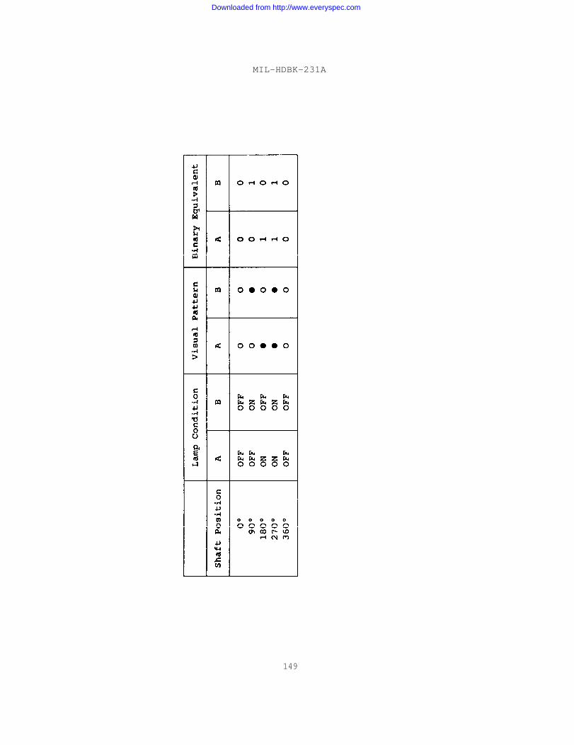
MIL-HDBK-231A
149
Downloaded from http://www.everyspec.com
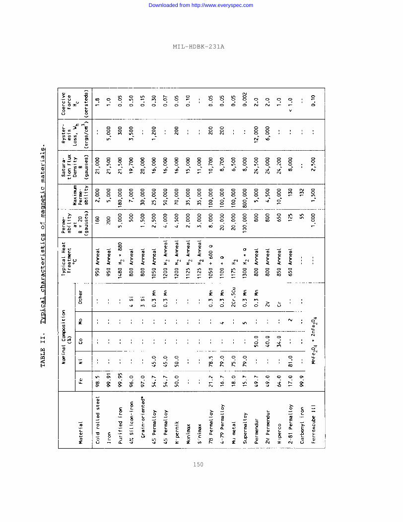
MIL-HDBK-231A
150
Downloaded from http://www.everyspec.com
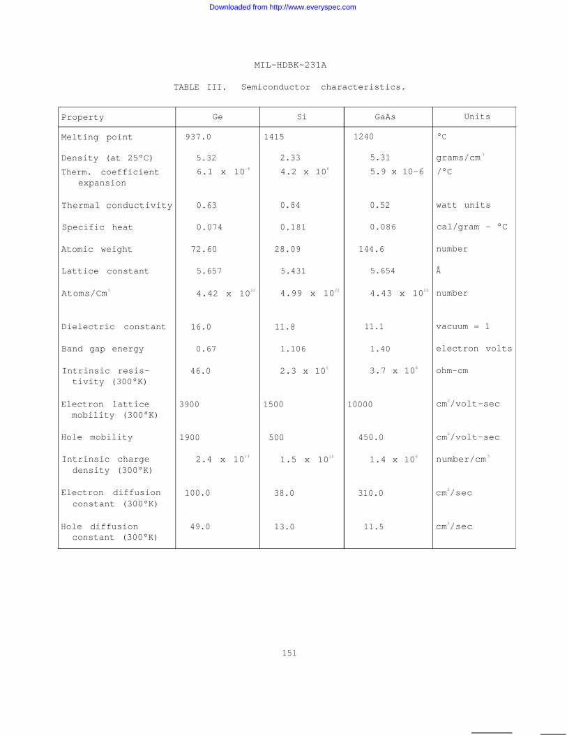
MIL-HDBK-231A
TABLE III. Semiconductor characteristics.
Property Ge Si GaAs Units
Melting point 937.0 1415 1240 °C
Density (at 25°C) 5.32 2.33 5.31 grams/cm 3
Therm. coefficient 6.1 x 10⁻⁶ 4.2 x 10⁶ 5.9 x 10⁻⁶ /°Cexpansion
Thermal conductivity 0.63 0.84 0.52 watt units
Specific heat 0.074 0.181 0.086 cal/gram - °C
Atomic weight 72.60 28.09 144.6 number
Lattice constant 5.657 5.431 5.654 Å
Atoms/Cm3 4.42 x 10²² 4.99 x 10²² 4.43 x 10²² number
Dielectric constant 16.0 11.8 11.1 vacuum = 1
Band gap energy 0.67 1.106 1.40 electron volts
Intrinsic resis- 46.0 2.3 x 10⁵ 3.7 x 10⁸ ohm-cmtivity (300°K)
Electron lattice 3900 1500 10000 cm2/volt-secmobility (300°K)
Hole mobility 1900 500 450.0 cm2/volt-sec
Intrinsic charge 2.4 x 10¹³ 1.5 x 10¹⁰ 1.4 x 10⁶ number/cm 3
density (300°K)
Electron diffusion 100.0 38.0 310.0 cm2/secconstant (300°K)
Hole diffusion 49.0 13.0 11.5 cm2/secconstant (300°K)
151
Downloaded from http://www.everyspec.com
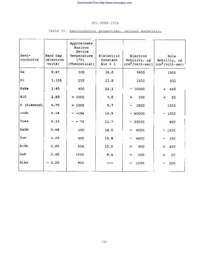
MIL-HDBK-231A
TABLE IV. Semiconductor properties, various materials.
152
Downloaded from http://www.everyspec.com
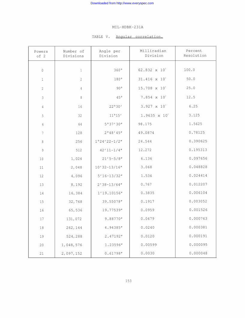
MIL-HDBK-231A
TABLE V. Angular correlation.
Powers Number of Angle per Milliradian Percent
of 2 Divisions Division Division Resolution
0 1 360° 62.832 x 10² 100.0
1 2 180° 31.416 x 10² 50.0
2 4 90° 15.708 x 10² 25.0
3 8 45° 7.854 x 10² 12.5
4 16 22°30’ 3.927 x 10² 6.25
5 32 11°15’ 1.9635 x 10² 3.125
6 64 5°37’30” 98.175 1.5625
7 128 2°48’45” 49.0874 0.78125
8 256 1°24’22-1/2” 24.544 0.390625
9 512 42’11-1/4” 12.272 0.195313
10 1,024 21’5-5/8” 6.136 0.097656
11 2,048 10’32-13/16” 3.068 0.048828
12 4,096 5’16-13/32” 1.534 0.024414
13 8,192 2’38-13/64” 0.767 0.012207
14 16,384 1’19.10156” 0.3835 0.006104
15 32,768 39.55078” 0.1917 0.003052
16 65,536 19.77539” 0.0959 0.001526
17 131,072 9.88770” 0.0479 0.000763
18 262,144 4.94385” 0.0240 0.000381
19 524,288 2.47192” 0.0120 0.000191
20 1,048,576 1.23596” 0.00599 0.000095
21 2,097,152 0.61798” 0.0030 0.000048
153
Downloaded from http://www.everyspec.com
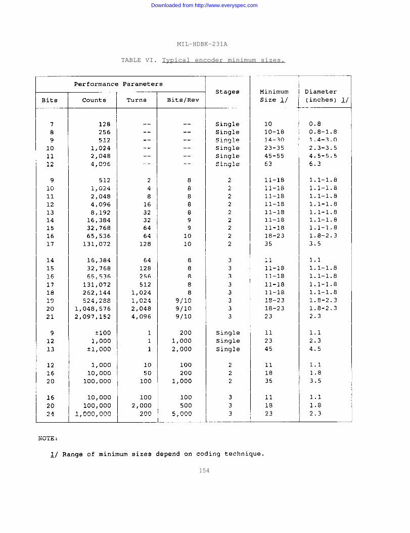
MIL-HDBK-231A
TABLE VI. Typical encoder minimum sizes.
154
Downloaded from http://www.everyspec.com
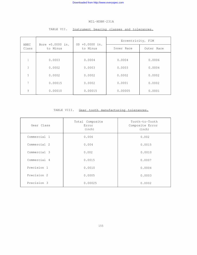
ABECClass
1
3
5
7
9
MIL-HDBK-231A
TABLE VII. Instrument bearing classes and tolerances.
Bore +0.0000 in.to Minus
0.0003
0.0002
0.0002
0.00015
0.00010
OD +0.0000 in.to Minus
0.0004
0.0003
0.0002
0.0002
0.00015
Eccentricity, FIM
Inner Race Outer Race
0.0004 0.0006
0.0003 0.0004
0.0002 0.0002
0.0001 0.0002
0.00005 0.0001
TABLE VIII. Gear tooth manufacturing tolerances.
Total Composite Tooth-to-ToothGear Class Error Composite Error
(inch) (inch)
Commercial 1 0.006 0.002
Commercial 2 0.004 0.0015
Commercial 3 0.002 0.0010
Commercial 4 0.0015 0.0007
Precision 1 0.0010 0.0004
Precision 2 0.0005 0.0003
Precision 3 0.00025 0.0002
155
Downloaded from http://www.everyspec.com
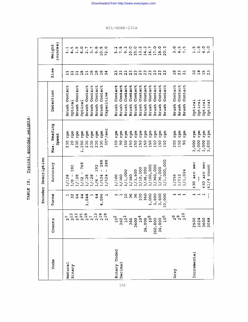
MIL-HDBK-231A
156
Downloaded from http://www.everyspec.com
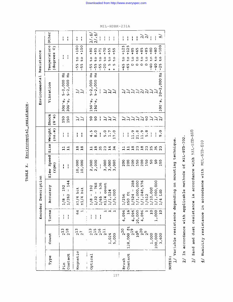
MIL-HDBK-231A
157
Downloaded from http://www.everyspec.com
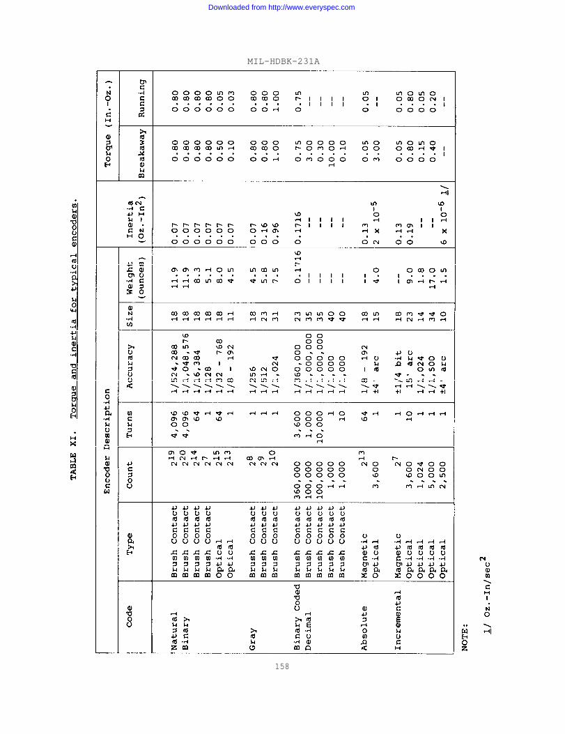
MIL-HDBK-231A
158
Downloaded from http://www.everyspec.com

MIL-HDBK-231A
TABLE XII. Bearing requirements.
Encoder Resolutionand Accuracy
Less than 8 bits
8 - 10 bits
More than 8 bits
Minimum RequiredABEC Rating
3
5
7
Excess-Three Decimal Natural Binary
D C B A d c b a
0 0 1 1 0 0 0 0 0
0 1 0 0 1 0 0 0 1
0 1 0 1 2 0 0 1 0
0 1 1 0 3 0 0 1 1
0 1 1 1 4 0 1 0 0
1 0 0 1 6 0 1 1 0
1 0 1 0 7 0 1 1 1
1 0 1 1 8 1 0 0 0
1 1 0 0 9 1 0 0 1
TABLE XIII. Excess-three to natural binary conversion truth table.
159
Downloaded from http://www.everyspec.com

MIL-HDBK-231A
TABLE XIV. Set-Reset selector circuit truth table.
Inputs output
Qt-1Set Reset Q t
o 1 0 1
1 1 0 1
0 1 1 1
1 1 1 1
0 0 1 0
1 0 1 0
0 0 0 0
1 0 0 1
TABLE XV. Set-Reset selector circuit control functions.
Control A
1
0
0
1
Encoder
Select E
1
1
0
0
Function
Follow
Store
Inhibit
Inhibit
Downloaded from http://www.everyspec.com

MIL-HDBK-231A
TABLE XVI. Set-Reset inter-disc or inter-belt selector circuit -truth table.
Inputs Outputs
Q t
Q t - 1R S ( Cl a g
2) ( Cl e a d
2)
0 1 0 0 1
1 1 0 0 1
0 0 1 1 0
1 0 1 1 0
0 0 0 0 1
1 0 0 1 0
1 1 1
0 1 1 Not Permitted
1 6 1
Downloaded from http://www.everyspec.com
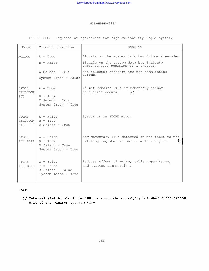
MIL-HDBK-231A
TABLE XVII. Sequence of operations for high reliability logic system.
Mode Circuit Operation Results
FOLLOW A = True Signals on the system data bus follow X encoder.
B = False Signals on the system data bus indicateinstantaneous position of X encoder.
X Select = True Non-selected encoders are not commutatingcurrent.
System Latch = False
LATCH A = True 2° bit remains True if momentary sensorSELECTOR conduction occurs.BIT B = True
X Select = TrueSystem Latch = True
STORE A = False System is in STORE mode.SELECTOR B = TrueBIT X Select = True
LATCH A = False Any momentary True detected at the input to theALL BITS B = True latching register stored as a True signal.
X Select = TrueSystem Latch = True
STORE A = False Reduces effect of noise, cable capacitance,
ALL BITS B = False and current commutation.X Select = FalseSystem Latch = True
162
Downloaded from http://www.everyspec.com
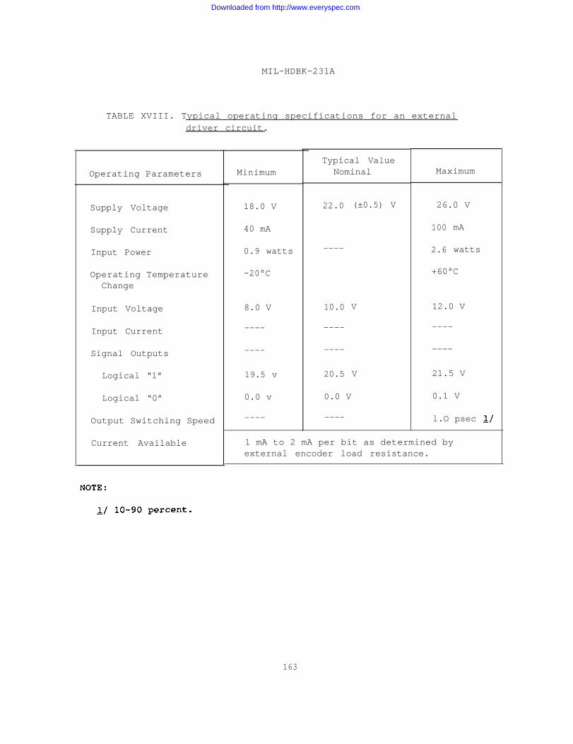
MIL-HDBK-231A
TABLE XVIII. Typical operating specifications for an externaldriver circuit.
Operating Parameters
Supply Voltage
Supply Current
Input Power
Operating TemperatureChange
Input Voltage
Input Current
Signal Outputs
Logical “1”
Logical “0”
Output Switching Speed
Current Available
Minimum
18.0 V
40 mA
0.9 watts
-20°C
8.0 V
----
----
19.5 v
0.0 v
----
Typical ValueNominal
22.0 (±0.5) V
----
10.0
----
----
20.5
0.0 V
----
V
V
Maximum
26.0 V
100
2.6
mA
watts
+60°C
12.0 V
----
----
21.5 V
0.1 V
l.O psec
1 mA to 2 mA per bit as determined byexternal encoder load resistance.
163
Downloaded from http://www.everyspec.com

MIL-HDBK-231A
Step
1
2
3
4
5
6
7
Step
1
2
3
4
TABLE XIX. Encoder test procedures.
Mechanical Checks
Procedure
Measure mechanical dimensions.
Measure clearances.
Check shaft end play.
check shaft radial play.
Check shaft runout.
check shaft torque (breakaway and running).
Check shaft perpendicularity.
Electrical Tests
Procedure
Using oscillograph, monitor encoder output count. Analyzeplot to ensure counts are in proper sequence, and thattransitions occur within tolerance.
For unit distance coded units, monitor output of unitdistance bit with oscillograph. Analyze plot to ensureminimum quantum bit width is within tolerance.
Analyze plot to ensure that edge noise is within tolerance.
Using autocorrelator, test for encoder dropout at maximumrated speed.
164
Downloaded from http://www.everyspec.com
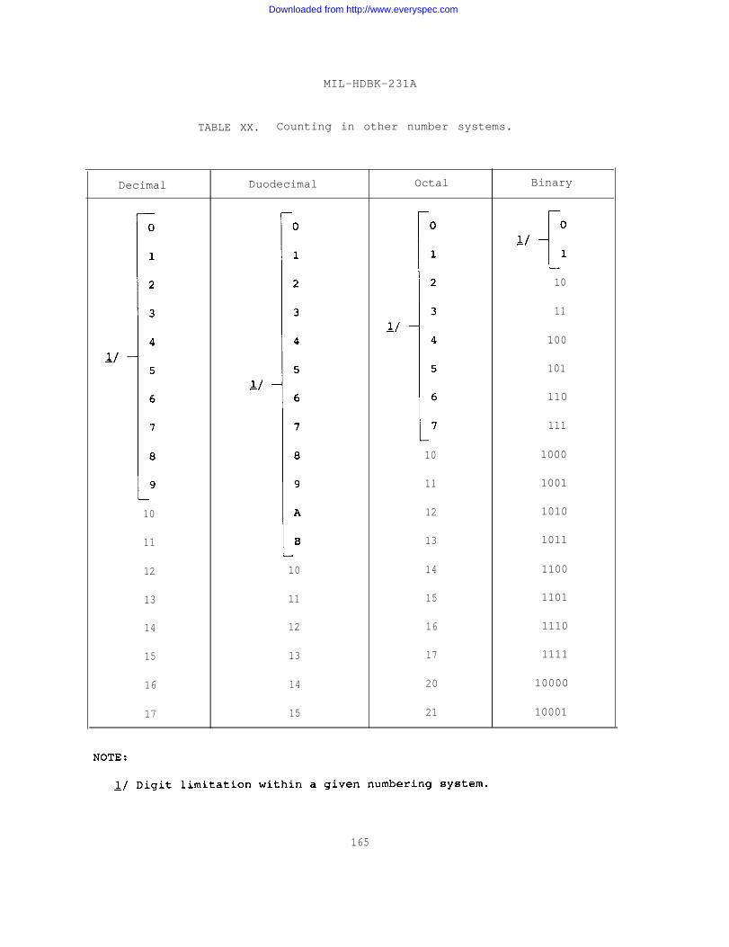
MIL-HDBK-231A
TABLE XX. Counting in other number systems.
Decimal Duodecimal Octal Binary
10
11
100
101
110
111
10 1000
11 1001
10 12 1010
11 13 1011
12 10 14 1100
13 11 15 1101
14 12 16 1110
15 13 17 1111
16 14 20 10000
17 15 21 10001
165
Downloaded from http://www.everyspec.com

MIL-HDBK-231A
TABLE XXI. Four-digit natural binary code and correspondingdecimal system numbers.
Natural Binary Natural Binary
Decimal Base 23 22 21 20 Decimal Base (24) 23 22 21 20
Number NumberWeight 8 4 2 1 Weight (16) 8 4 2 1
0 0 0 0 0 9 1 0 0 1
1 0 0 0 1 10 1 0 1 0
2 0 0 1 0 11 1 0 1 1
3 0 0 1 1 12 1 1 0 0
4 0 1 0 0 13 1 1 0 1
5 0 1 0 1 14 1 0 0 1
6 0 1 1 0 15 1 1 1 1
7 0 1 1 1 16 1 0 0 0 0
8 1 0 0 0
NOTE :Exponent.
TABLE XXII. Incremental code and corresponding decimal system numbers.
Decimal Incremental Decimal IncrementalNumber Number Number Number
0 00 6 10
1 01 7 11
2 10 8 00
3 11 9 01
4 00 10 10
5 01 11 11
166
Downloaded from http://www.everyspec.com

MIL-HDBK-231A
TABLE XXIII. 8-4-2-1 binary coded decimal.
Decimal Digit
0
1
2
3
4
5
6
7
8
9
8-4-2-1 Binary Coded Decimal
0000
0001
0010
0011
0100
0101
0110
0111
1000
1001
TABLE XXIV. Binary coded octal system.
Decimal Number
0
1
2
3
4
5
6
7
Binary Coded Octal Number
000
001
010
011
100
101
110
111
167
Downloaded from http://www.everyspec.com
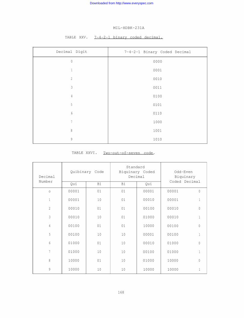
MIL-HDBK-231A
TABLE XXV. 7-4-2-1 binary coded decimal.
Decimal Digit 7-4-2-1 Binary Coded Decimal
0 0000
1 0001
2 0010
3 0011
4 0100
5 0101
6 0110
7 1000
8 1001
9 1010
TABLE XXVI. Two-out-of-seven code.
StandardQuibinary Code Biquinary Coded Odd-Even
Decimal Decimal BiquinaryNumber
Qui BiCoded Decimal
Bi Qui
o 00001 01 01 00001 00001 0
1 00001 10 01 00010 00001 1
2 00010 01 01 00100 00010 0
3 00010 10 01 01000 00010 1
4 00100 01 01 10000 00100 0
5 00100 10 10 00001 00100 1
6 01000 01 10 00010 01000 0
7 01000 10 10 00100 01000 1
8 10000 01 10 01000 10000 0
9 10000 10 10 10000 10000 1
168
Downloaded from http://www.everyspec.com
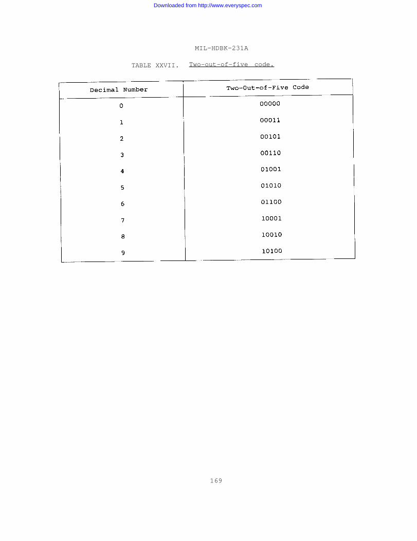
MIL-HDBK-231A
TABLE XXVII. Two-out-of-five code.
169
Downloaded from http://www.everyspec.com
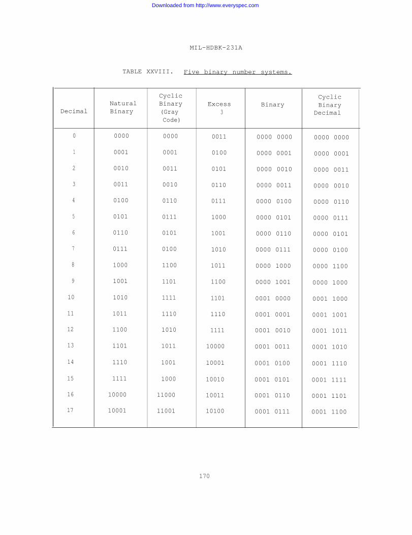
MIL-HDBK-231A
TABLE XXVIII. Five binary number systems.
Cyclic CyclicNatural Binary Excess Binary Binary
Decimal Binary (Gray 3 DecimalCode)
0 0000 0000 0011 0000 0000 0000 0000
1 0001 0001 0100 0000 0001 0000 0001
2 0010 0011 0101 0000 0010 0000 0011
3 0011 0010 0110 0000 0011 0000 0010
4 0100 0110 0111 0000 0100 0000 0110
5 0101 0111 1000 0000 0101 0000 0111
6 0110 0101 1001 0000 0110 0000 0101
7 0111 0100 1010 0000 0111 0000 0100
8 1000 1100 1011 0000 1000 0000 1100
9 1001 1101 1100 0000 1001 0000 1000
10 1010 1111 1101 0001 0000 0001 1000
11 1011 1110 1110 0001 0001 0001 1001
12 1100 1010 1111 0001 0010 0001 1011
13 1101 1011 10000 0001 0011 0001 1010
14 1110 1001 10001 0001 0100 0001 1110
15 1111 1000 10010 0001 0101 0001 1111
16 10000 11000 10011 0001 0110 0001 1101
17 10001 11001 10100 0001 0111 0001 1100
170
Downloaded from http://www.everyspec.com
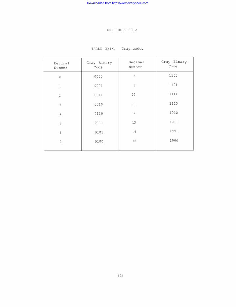
MIL-HDBK-231A
TABLE XXIX. Gray code.
Decimal Gray Binary Decimal Gray Binary
Number Code Number Code
0 0000 8 1100
1 0001 9 1101
2 0011 10 1111
3 0010 11 1110
4 0110 12 1010
5 0111 13 1011
6 0101 14 1001
7 0100 15 1000
171
Downloaded from http://www.everyspec.com
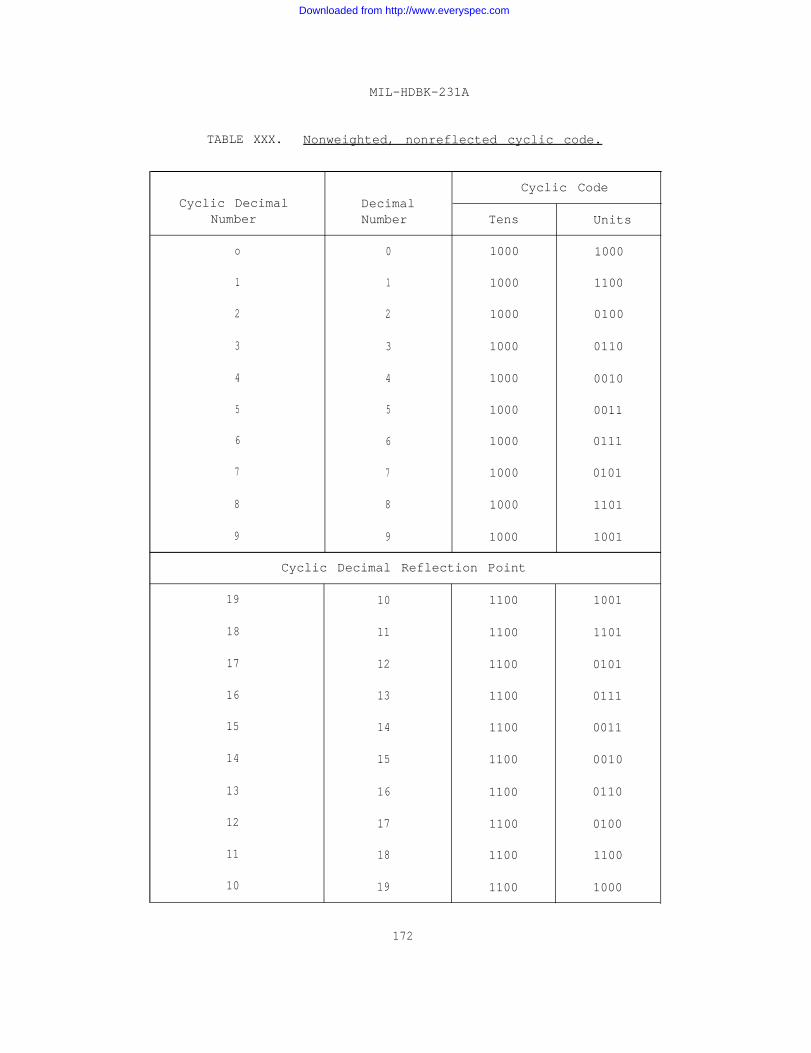
MIL-HDBK-231A
TABLE XXX. Nonweighted, nonreflected cyclic code.
Cyclic CodeCyclic Decimal Decimal
Number Number Tens Units
o 0 1000 1000
1 1 1000 1100
2 2 1000 0100
3 3 1000 0110
4 4 1000 0010
5 5 1000 0011
6 6 1000 0111
7 7 1000 0101
8 8 1000 1101
9 9 1000 1001
Cyclic Decimal Reflection Point
19 10 1100 1001
18 11 1100 1101
17 12 1100 0101
16 13 1100 0111
15 14 1100 0011
14 15 1100 0010
13 16 1100 0110
12 17 1100 0100
11 18 1100 1100
10 19 1100 1000
172
Downloaded from http://www.everyspec.com
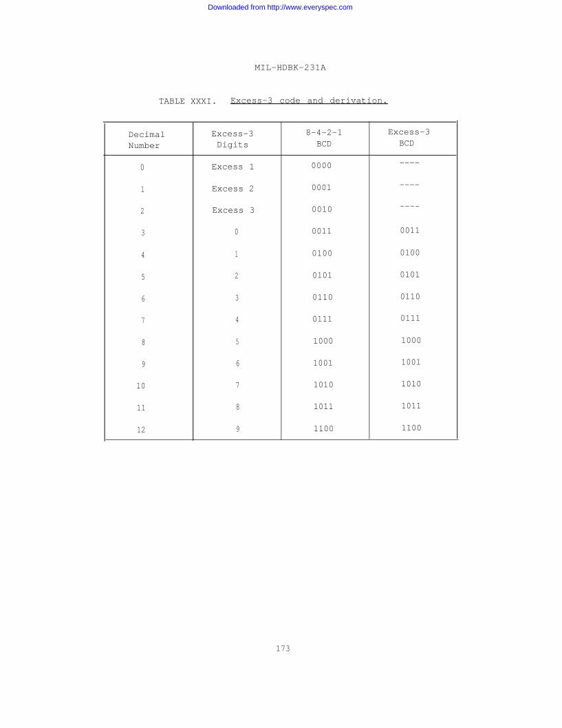
MIL-HDBK-231A
TABLE XXXI. Excess-3 code and derivation.
Decimal Excess-3 8-4-2-1 Excess-3
Number Digits BCD BCD
0 Excess 1 0000 ----
1 Excess 2 0001 ----
2 Excess 3 0010 ----
3 0 0011 0011
4 1 0100 0100
5 2 0101 0101
6 3 0110 0110
7 4 0111 0111
8 5 1000 1000
9 6 1001 1001
10 7 1010 1010
11 8 1011 1011
12 9 1100 1100
173
Downloaded from http://www.everyspec.com
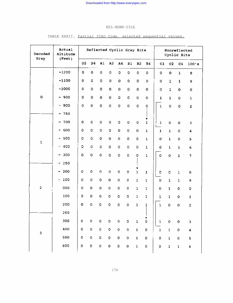
MIL-HDBK-231A
TABLE XXXII. Partial ICAO Code, selected sequential values.
174
Downloaded from http://www.everyspec.com
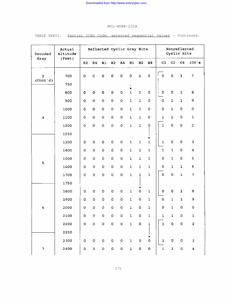
MIL-HDBK-231A
TABLE XXXII. Partial ICAO Code, selected sequential values - Continued.
175
Downloaded from http://www.everyspec.com
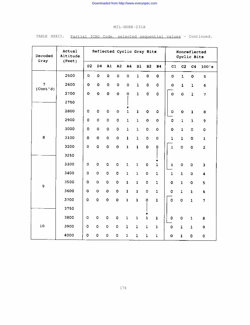
MIL-HDBK-231A
TABLE XXXII. Partial ICAO Code, selected sequential values - Continued.
176
Downloaded from http://www.everyspec.com
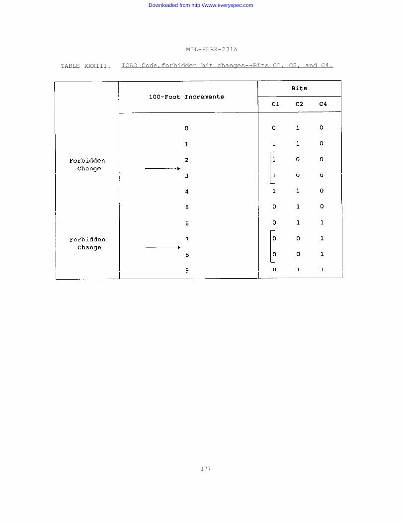
MIL-HDBK-231A
TABLE XXXIII. ICAO Code,forbidden bit changes--Bits C1, C2, and C4.
177
Downloaded from http://www.everyspec.com
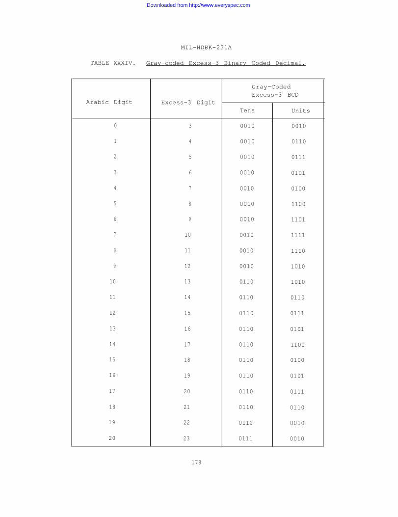
MIL-HDBK-231A
TABLE XXXIV. Gray-coded Excess-3 Binary Coded Decimal.
Gray-CodedExcess-3 BCD
Arabic Digit Excess-3 DigitTens Units
0 3 0010 0010
1 4 0010 0110
2 5 0010 0111
3 6 0010 0101
4 7 0010 0100
5 8 0010 1100
6 9 0010 1101
7 10 0010 1111
8 11 0010 1110
9 12 0010 1010
10 13 0110 1010
11 14 0110 0110
12 15 0110 0111
13 16 0110 0101
14 17 0110 1100
15 18 0110 0100
16 19 0110 0101
17 20 0110 0111
18 21 0110 0110
19 22 0110 0010
20 23 0111 0010
178
Downloaded from http://www.everyspec.com

MIL-HDBK-231A
TABLE XXXV. Two-out-of-five coding.
Arabic Digit Two-Out-of-Five Code7 4 2 1 P
0 1 1 0 0 0
1 0 0 0 1 1
2 0 0 1 0 1
3 0 0 1 1 0
4 0 1 0 0 1
5 0 1 0 1 0
6 0 1 1 0 0
7 1 0 0 0 1
8 1 0 0 1 0
9 1 0 1 0 0
TABLE XXXVI. Unit distance code for minutes or secondswith one-bit complement.
Arabic Numeral Code
0 001
1 011
2 010
3 110
4 111
5 101
179
Downloaded from http://www.everyspec.com

Hours
0
1
2
3
4
5
6
7
8
9
10
11
12
13
14
15
16
17
18
19
20
21
22
23
MIL-HDBK-231A
TABLE XXXVII. Unit distance code of 0-23 hours.
Hours + 4
4
5
6
7
8
9
10
11
12
13
14
15
16
17
18
19
20
21
22
23
24
25
26
27
Binary Code1 6 8 4 2 1
0
0
0
0
0
0
0
0
0
0
0
0
1
1
1
1
1
1
1
1
1
1
1
1
0
0
0
0
1
1
1
1
1
1
1
1
0
0
0
0
0
0
0
0
1
1
1
1
1
1
1
1
0
0
0
0
1
1
1
1
0
0
0
0
1
1
1
1
0
0
0
0
180
0
0
1
1
0
0
1
1
0
0
1
1
0
0
1
1
0
0
1
1
0
0
1
1
0
1
0
1
0
1
0
1
0
1
0
1
0
1
0
1
0
1
0
1
0
1
0
1
Gray Code
o
0
0
0
0
0
0
0
0
0
0
0
1
1
1
1
1
1
1
1
1
1
1
1
0
0
0
0
1
1
1
1
1
1
1
1
1
1
1
1
1
1
1
1
0
0
0
0
1
1
1
1
1
1
1
1
0
0
0
0
0
0
0
0
1
1
1
1
1
1
1
1
1
1
0
0
0
0
1
1
1
1
0
0
0
0
1
1
1
1
0
0
0
0
1
1
0
1
1
0
0
1
1
0
0
1
1
0
0
1
1
0
0
1
1
0
0
1
1
0
Downloaded from http://www.everyspec.com
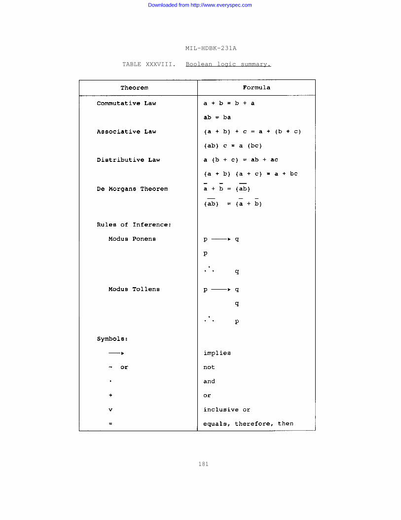
MIL-HDBK-231A
TABLE XXXVIII. Boolean logic summary.
181
Downloaded from http://www.everyspec.com

MIL-HDBK-231A
TABLE XXXIX. Truth table for AND logic equation.
ConditionNumber
1
2
3
4
5
6
7
8
SwitchA
0
1
0
1
0
1
0
1
SwitchB
0
0
1
1
0
0
1
1
LampC
0
0
0
0
1
1
0
1
TABLE XL. Set-Reset truth table.
Result
1
1
1
0
0
0
0
1
Selector InputsPast Present OutputLSB Set Reset (Corrected)
0 1 0 1
1 1 0 1
0 1 1 1
1 1 1 1
0 0 1 0
1 0 1 0
0 0 0 0
1 0 0 1
182
Downloaded from http://www.everyspec.com

MIL-HDBK-231A
TABLE XLI. Encoder specification checklist.
Parameter
OUTPUT CODE
ANTI-AMBIGUITY LOGIC
OUTPUT NOTATION
MECHANICAL APPLICATIONS
Options
8-4-2-1 Binary Coded DecimalNatural BinaryGray BinaryCyclic DecimalICAO (MOA-Gillham)Excess-3 Binary Coded DecimalExcess-3 Gray CodeBiquinaryTwo-Out-of-Five Binary Coded Decimal4-2-2-1 BinaryIncremental:
With Zero Index ReferenceWithout Zero Index Reference
Window CodeUnit Distance CodeV-ScanSelf-Selecting V-ScanM-ScanU-ScanSelf-Selecting U-Scan
LinearDegrees, MinutesHours, MinutesSine-CosineSquare Root FunctionsOther Trigonometric FunctionsLongitudeLatitudeThermocouple EMF - Temperature Curve
Copper ConstantanIron ConstantanChromel AlumelOther Thermocouples
Resistance Bulb Temperature CurveDewcell Temperature CurveOther Non-Linear Range
Maximum Reading Speed in rpmMaximum Slewing Speed in rpmAverage Reading Speed in rpmAverage Slewing Speed in rpmLife: (1) Revolutions (2) HoursMaximum Allowable Torque in Oz.-In. :
(1) Breakaway (2) RunningMaximum Allowable Momment of Inertia in Gm-Cm2
183
Downloaded from http://www.everyspec.com

MIL-HDBK-231A
TABLE XLI. Encoder specification checklist - Continued.
Parameter
MECHANICAL APPLICATIONS(Continued)
ELECTRICAL APPLICATIONS
Options
Transition Accuracy Required: (1) Percentof One Count, (2) Angle in Degree of Arc
Shaft DiameterShaft LengthShaft Type:
SolidHollowPlain, Slot, Spline, or PinionThrough Shaft
Mounting Size:Size 11 SynchroSize 15 SynchroSize 18 SynchroSize 23 SynchroSize 31 SynchroSize 35 Synchro
Case Diameter:SizeSizeSizeSizeSizeSizeSizeSizeSize
111518233135405565
1.0621.5001.7502.2503.0623.5004.0005.5006.500
MountMountMountMountMountMount
in.in.in.in.in.in.in.in.in.
Case Length in Inches (less shaft)Maximum Tolerable WeightOutput Connection:
Pigtail LeadsCable with ConnectorIntegral ConnectorTerminals
184
Maximum Load Voltage per DigitMaximum Load Current per digitLoad Impedance in OhmsLoad:
Pure ResistanceReactance
Drive Circuits:External to EncoderInternal
Diodes:ExternalInternalPolarity
Downloaded from http://www.everyspec.com

MIL-HDBK-231A
TABLE XLI. Encoder specification checklist - Continued.
Parameter Options
ENVIRONMENT Shock in G’sVibration Range in HertzOperating Temperature RangeHumidityApplication:
Ground MilitaryAirborneLaboratoryIndustrialSpace
GENERAL CHARACTERISTICS Rotation for Ascending Count:(1) Clockwise (2) Counterclockwise
Number of Counts for Full Scale OutputNumber of Turns for Full Scale Output
(Multi-Turn)Number of Counts per Turn (Multi-Turn)Degree of Rotation for Full Count (Single
Turn )Single or Double Zero Count and Sign of
output
MISCELLANEOUS Auxiliary External Circuits:FilterBufferDrive CircuitsTranslatorStorage Circuitsoutputs:
SerialParallelBoth
185
Downloaded from http://www.everyspec.com
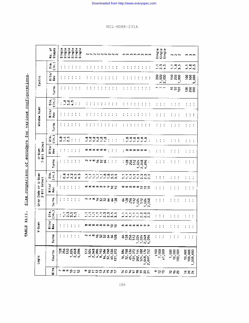
MIL-HDBK-231A
186
Downloaded from http://www.everyspec.com

MIL-HDBK-231A
TABLE XLIII. Lubricant and bearing materialconsiderations for high temperatureoperation.
Temperature Consideration(°F)
275° Temperature limit for phenolic retainer.
300° Limit for 52100 steel and synthetic diester andmineral oil lubricants.
350° Limit for untreated 400C stainless steel and siliconlubricants.
Limit for available high temperature grease ofsuitable characteristics.
600° Limit for heat-treated 440C stainless steel.
Above 600° Gas lubrication and special metals self-generatingto 1500° natural oxided lubrication and possibly molybdenum
disulphide to 750°F.
400°
TABLE XLIV. Lubricant and bearing material considerationsfor high vacuum operation.
Pressure(mm Hg) Consideration or Solution
10-5 Normal bearing and lubricant limit for full life.
10-7 Mineral oil lubricants below 300°F or synthetic diesteroil. Reduce internal pressure by shielded bearings.Use phenolic retainers.
1 0- 9 Use silicon grease.
1 0- 1 1 Experimental areas include metallic film lubrication.
187
Downloaded from http://www.everyspec.com

MIL-HDBK-231A
TABLE XLV. Lubricant and bearing maerial considerationsfor nuclear radiation environments.
107
108
Radiation Level(Roentgens) Applicable Lubricant
106 Use silicon greases and fluids to 8 x 10⁶ roentgensand metal retainers above 5 x 10⁶ roentgens.
Use diester oils to 5 x 10⁷ roentgens or mineral oilsbelow 8 x 10⁷ roentgens.
Use of special greases possible to 3 x 10⁸ roentgens.
TABLE XLVI. Lubricant considerations for low temperature operations.
Temperature(°F) Applicable Lubricant
To 0° Use mineral oils down to 0 degrees.
To -45° Use polyalkylene glycol.
To -55° Use silicon fluids or grease.
To -100° Use diester oil.
188
Downloaded from http://www.everyspec.com

MIL-HDBK-231A
TABLE XLVII. Designation of encoder type.
Type Designation
Capacitive C
Eddy Current E
Magnetic M
Contact K
Optical (lamp) L
Optical (LED) S
Other W
TABLE XLVIII. Designation of code and scan.
Code and Scan Designation
Natural Binary, Line-Scan ANatural Binary, U-Scan B
Natural Binary, V-Scan C
Natural Binary, M-Scan N
Reflected (Cyclic) Binary (Gray Code) Line Scan D
Reflected (Cyclic) Binary (Gray Code) Lead-Lag PBinary Coded Decimal, Line-Scan EBinary Coded Decimal, U-Scan FBinary Coded Decimal, V-Scan GBinary Coded Decimal, M-Scan MDecimal, Line-Scan H
Incremental (With Zero Reference) JIncremental (Without Zero Reference) K
Altitude Reporting (ICAO) U
Other W
189
Downloaded from http://www.everyspec.com

MIL-HDBK-231A
TABLE XLIX. Designation of logic and output.
Logic output Designation
External Parallel J
External Serial K
Internal Parallel L
Internal Serial M
TABLE L. Designation of function.
Function Designation
Linear R
Sine-Cosine s
Tangent T
Exponential x
Logarithmic z
Other w
190
Downloaded from http://www.everyspec.com
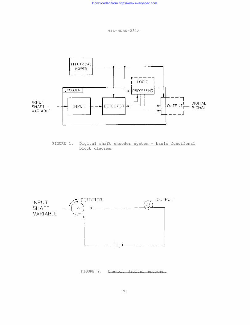
MIL-HDBK-231A
FIGURE 1. Digital shaft encoder system - basic functionalblock diagram.
FIGURE 2. One-bit digital encoder.
191
Downloaded from http://www.everyspec.com
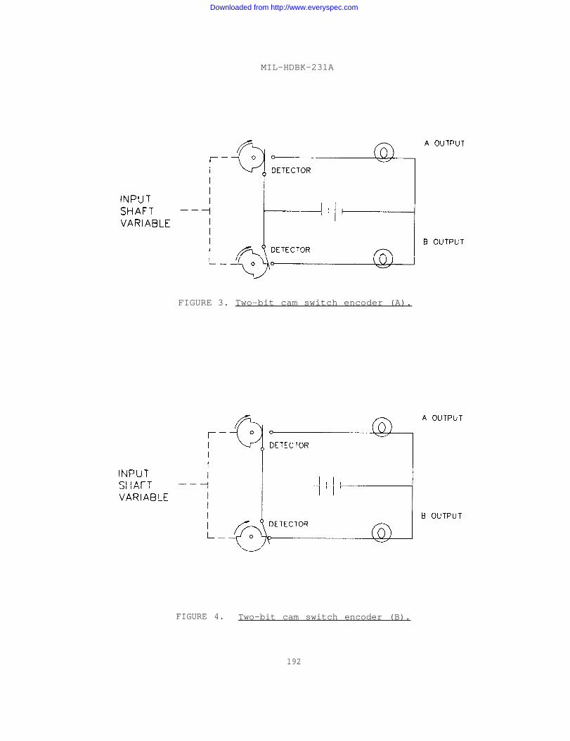
MIL-HDBK-231A
FIGURE 3. Two-bit cam switch encoder (A).
FIGURE 4. Two-bit cam switch encoder (B).
192
Downloaded from http://www.everyspec.com
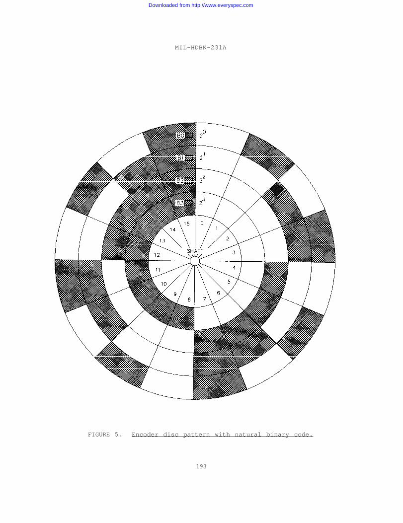
MIL-HDBK-231A
FIGURE 5. Encoder disc pattern with natural binary code.
193
Downloaded from http://www.everyspec.com
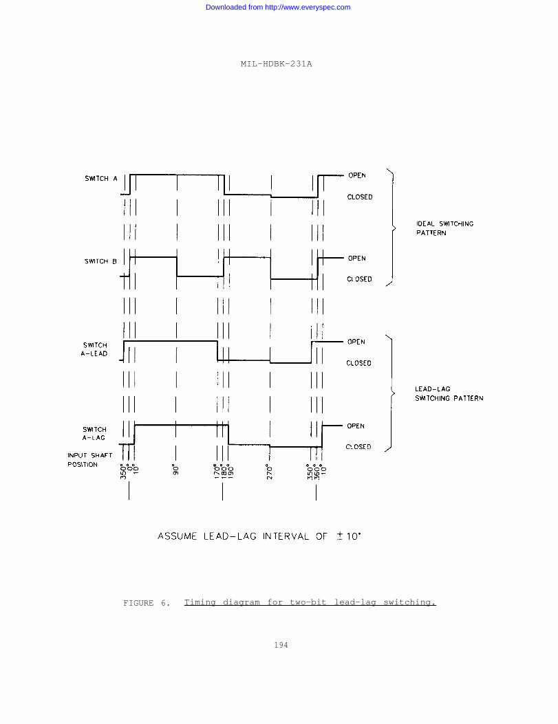
MIL-HDBK-231A
FIGURE 6. Timing diagram for two-bit lead-lag switching.
194
Downloaded from http://www.everyspec.com
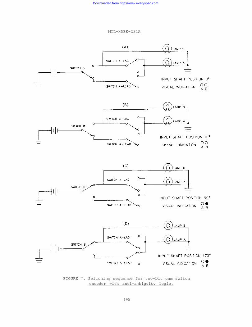
MIL-HDBK-231A
FIGURE 7. Switching sequence for two-bit cam switchencoder with anti-ambiguitv logic.
195
Downloaded from http://www.everyspec.com
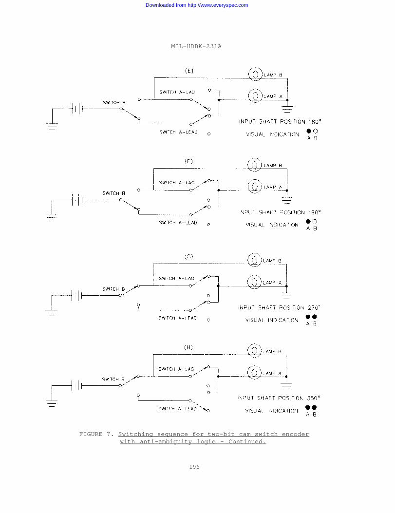
MIL-HDBK–231A
FIGURE 7. Switching sequence for two-bit cam switch encoderwith anti-ambiguity logic - Continued.
196
Downloaded from http://www.everyspec.com
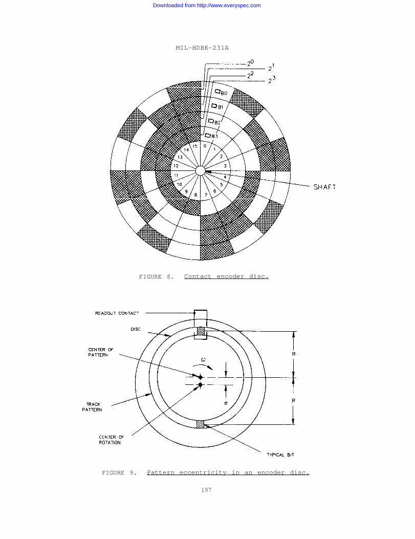
MIL-HDBK-231A
FIGURE 8. Contact encoder disc.
FIGURE 9. Pattern eccentricity in an encoder disc.
197
Downloaded from http://www.everyspec.com

MIL-HDBK-231A
FIGURE 10. Pin contact encoder.
198
Downloaded from http://www.everyspec.com

MIL-HDBK-231A
1.
2.
3.
4.
5.
6.
7.
8.
Outer Case
High Speed commutator Disc
High Speed Pin Cage
Gear Box
Low Speed Pin Cage
Low Speed Disc
Connector Shell
Connector Mounted Decoding Package
FIGURE 11. Pin encoder, cutaway view.
199
Downloaded from http://www.everyspec.com
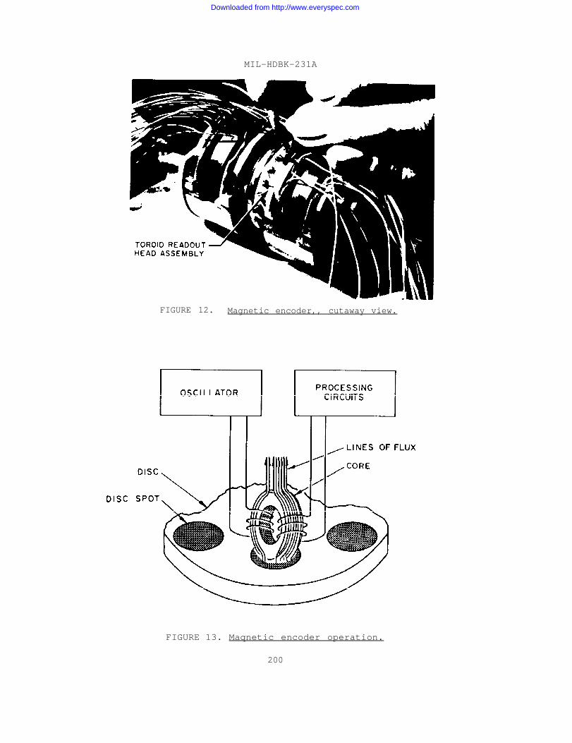
MIL-HDBK-231A
FIGURE 12. Magnetic encoder,, cutaway view.
FIGURE 13. Maqnetic encoder operation.
200
Downloaded from http://www.everyspec.com
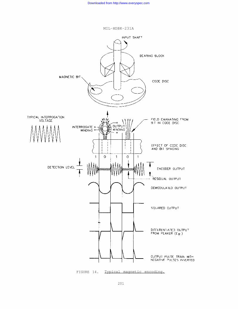
MIL-HDBK-231A
FIGURE 14. Typical magnetic encoding.
201
Downloaded from http://www.everyspec.com
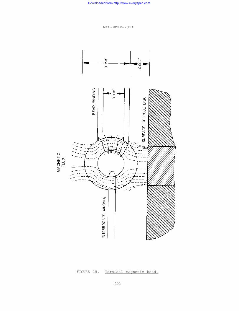
MIL-HDBK-231A
FIGURE 15. Toroidal magnetic head.
202
Downloaded from http://www.everyspec.com
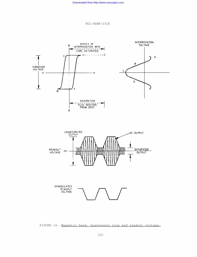
MIL-HDBK-231A
FIGURE 16. Magnetic head, hysteresis loop and readout voltage.
203
Downloaded from http://www.everyspec.com
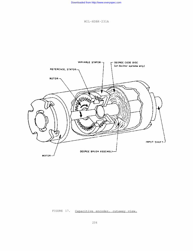
MIL-HDBK-231A
FIGURE 17. Capacitive encoder, cutaway view.
204
Downloaded from http://www.everyspec.com
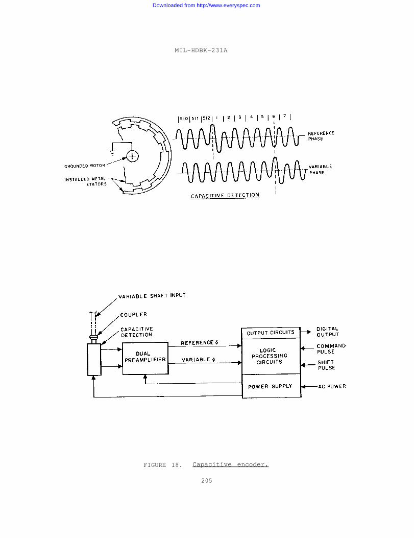
MIL-HDBK-231A
FIGURE 18. Capacitive encoder.
205
Downloaded from http://www.everyspec.com
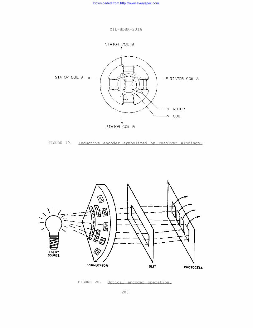
MIL-HDBK-231A
FIGURE 19. Inductive encoder symbolized by resolver windings.
FIGURE 20. Optical encoder operation.
206
Downloaded from http://www.everyspec.com
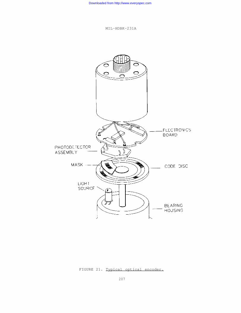
MIL-HDBK-231A
FIGURE 21. Typical optical encoder.
207
Downloaded from http://www.everyspec.com
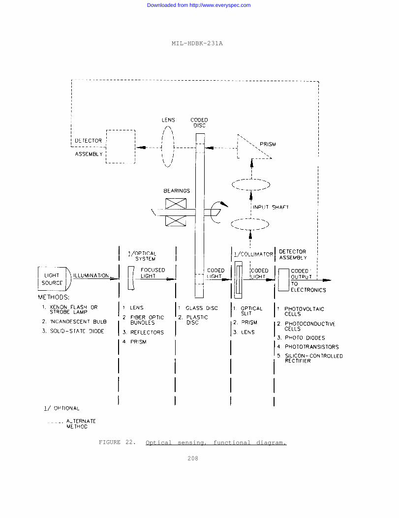
MIL-HDBK-231A
FIGURE 22. Optical sensing, functional diagram.
208
Downloaded from http://www.everyspec.com
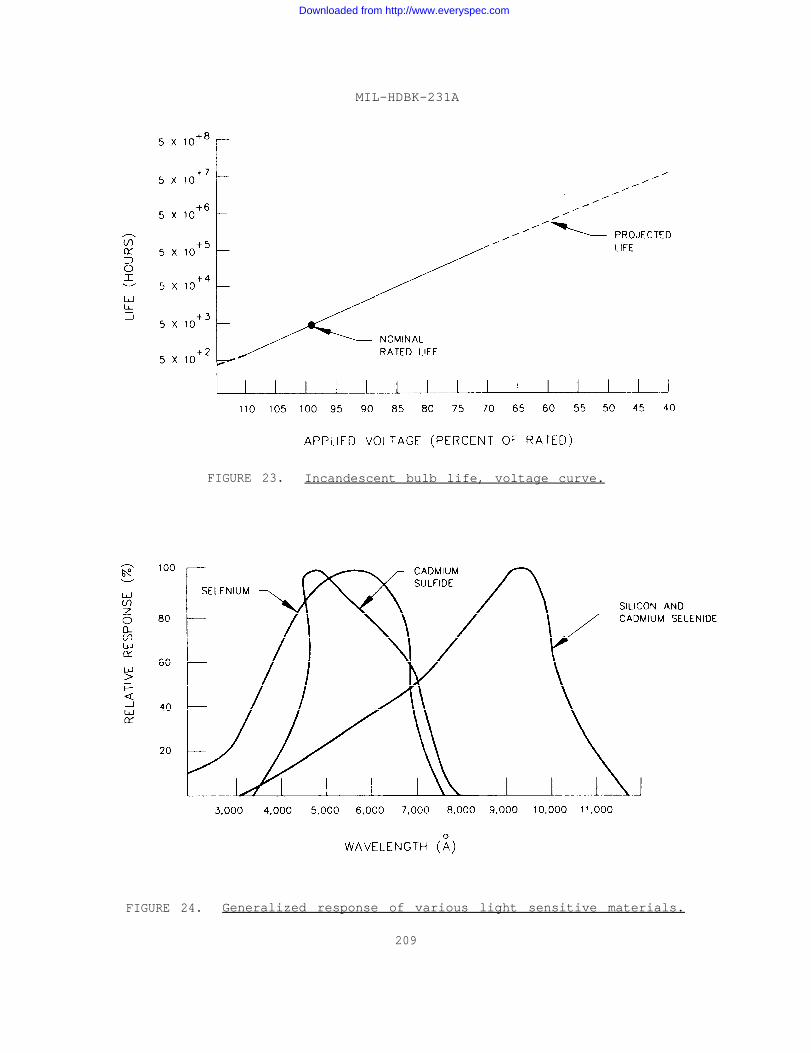
MIL-HDBK-231A
FIGURE 23. Incandescent bulb life, voltage curve.
FIGURE 24. Generalized response of various light sensitive materials.
209
Downloaded from http://www.everyspec.com
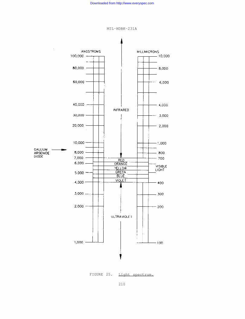
MIL-HDBK-231A
FIGURE 25. Light spectrum.
210
Downloaded from http://www.everyspec.com
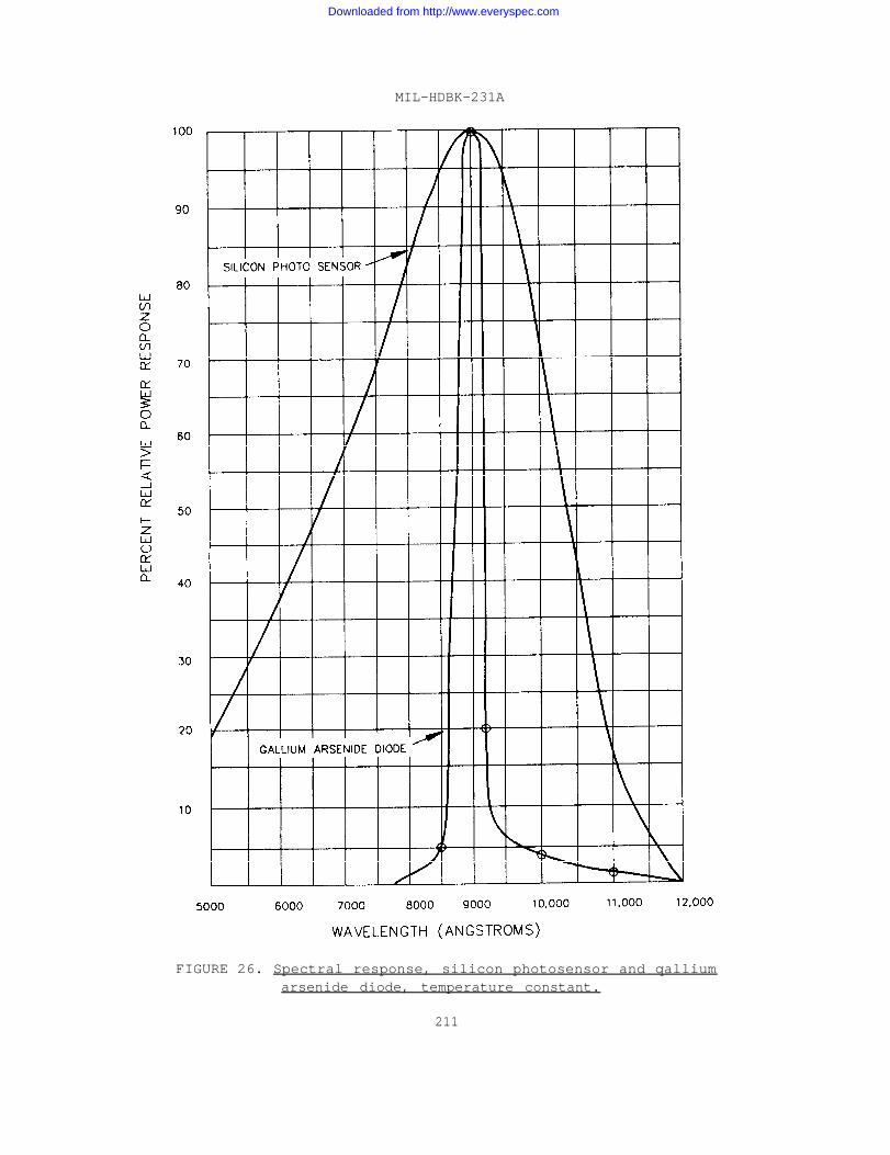
MIL-HDBK-231A
FIGURE 26. Spectral response, silicon photosensor and qalliumarsenide diode, temperature constant.
211
Downloaded from http://www.everyspec.com
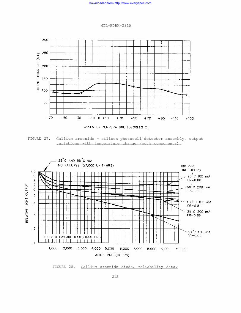
MIL-HDBK-231A
FIGURE 27. Gallium arsenide - silicon photocell detector assembly, outputvariations with temperature change (both components).
FIGURE 28. Gallium arsenide diode, reliability data.
212
Downloaded from http://www.everyspec.com
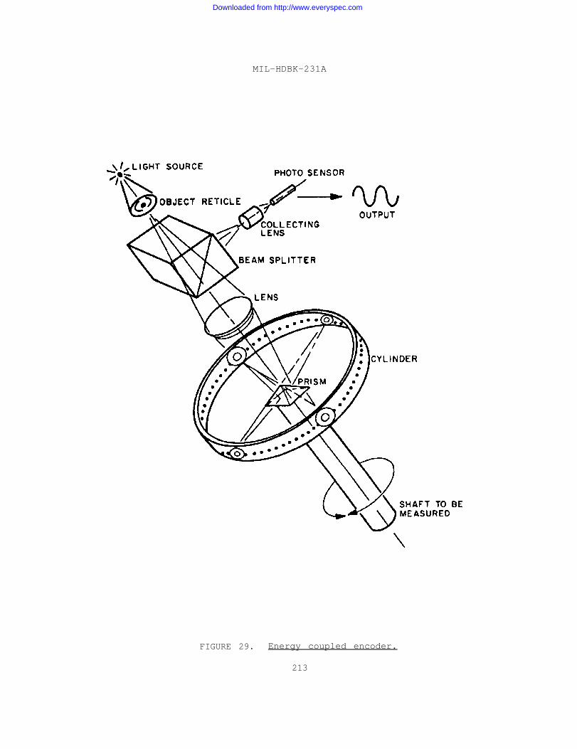
MIL-HDBK-231A
FIGURE 29. Energy coupled encoder.
213
Downloaded from http://www.everyspec.com
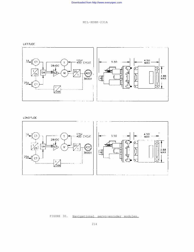
MIL-HDBK-231A
FIGURE 30. Navigational servo-encoder modules.
214
Downloaded from http://www.everyspec.com
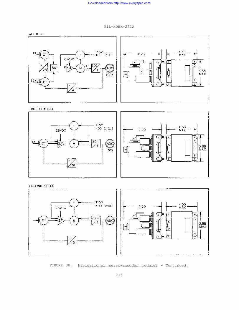
MIL-HDBK-231A
FIGURE 30. Navigational servo-encoder modules - Continued.
215
Downloaded from http://www.everyspec.com
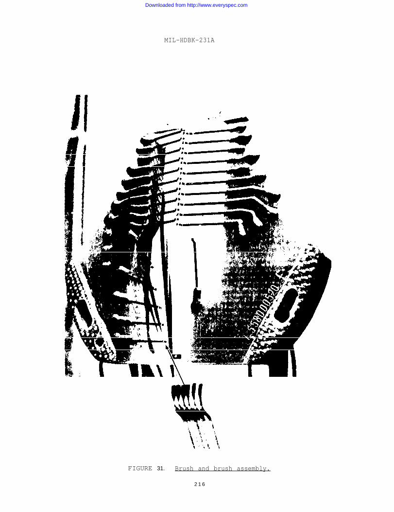
MIL-HDBK-231A
FIGURE 31. Brush and brush assembly.
2 1 6
Downloaded from http://www.everyspec.com

MIL-HDBK-231A
FIGURE 32. Brush encoder, cutaway view.
217
Downloaded from http://www.everyspec.com
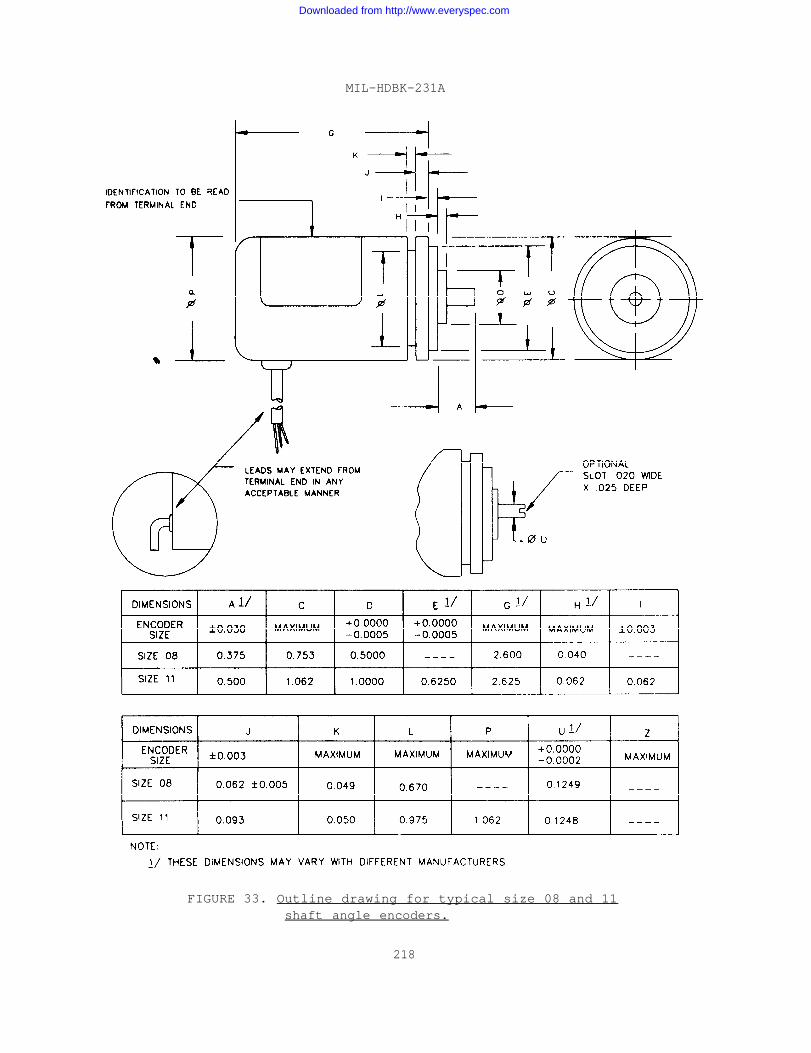
MIL-HDBK-231A
FIGURE 33. Outline drawing for typical size 08 and 11shaft angle encoders.
218
Downloaded from http://www.everyspec.com
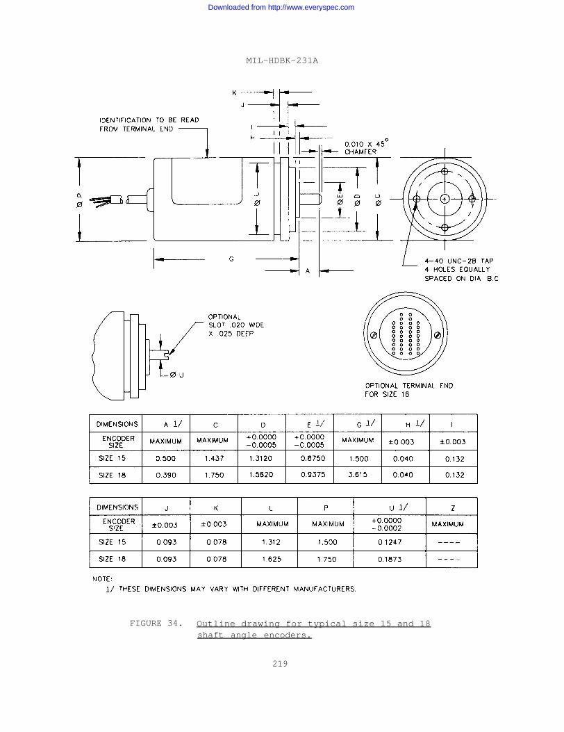
MIL-HDBK-231A
FIGURE 34. Outline drawing for typical size 15 and 18shaft angle encoders.
219
Downloaded from http://www.everyspec.com
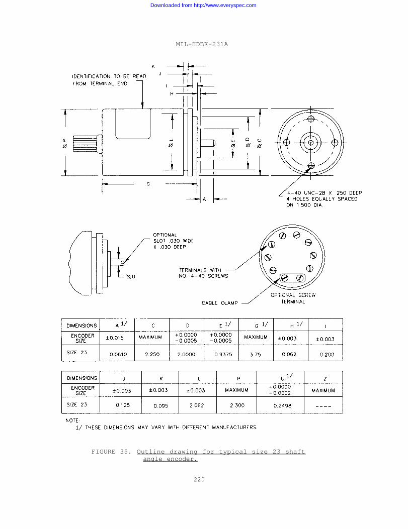
MIL-HDBK-231A
FIGURE 35. Outline drawing for typical size 23 shaftangle encoder.
220
Downloaded from http://www.everyspec.com
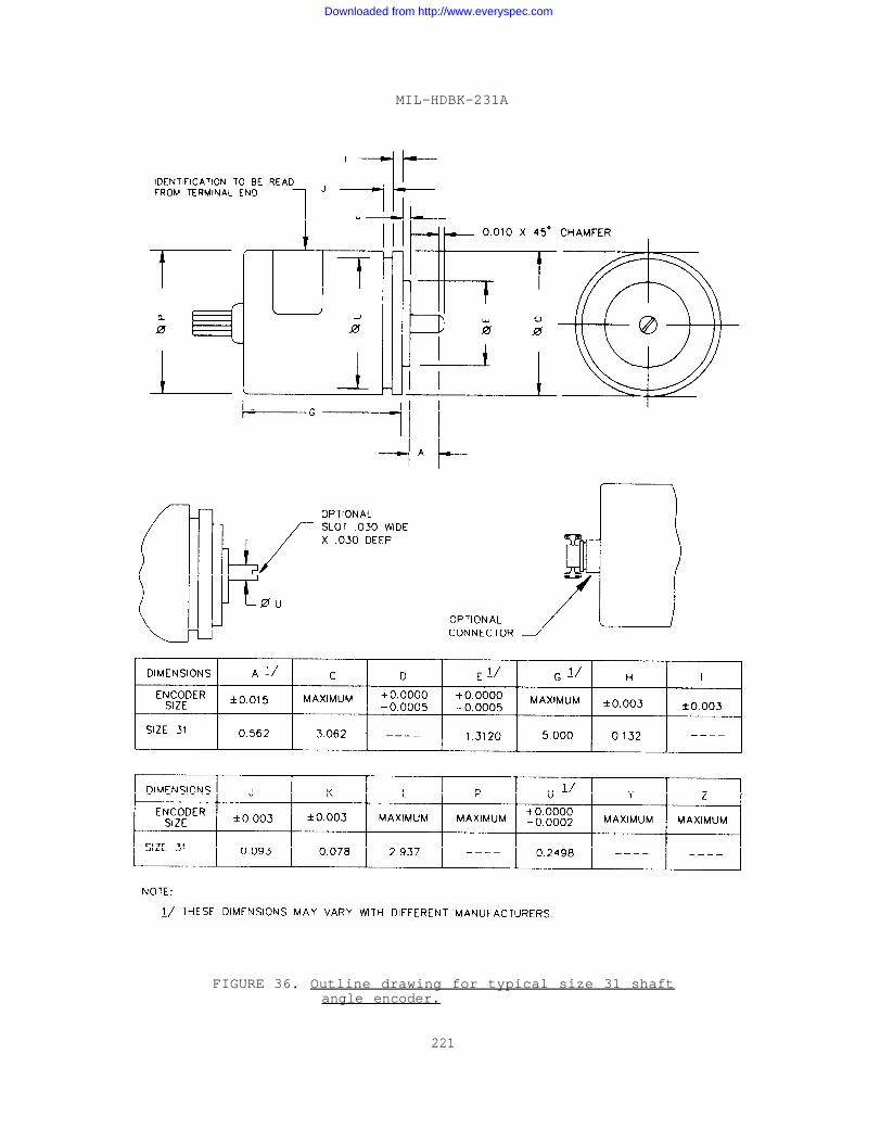
MIL-HDBK-231A
FIGURE 36. Outline drawing for typical size 31 shaftangle encoder.
221
Downloaded from http://www.everyspec.com
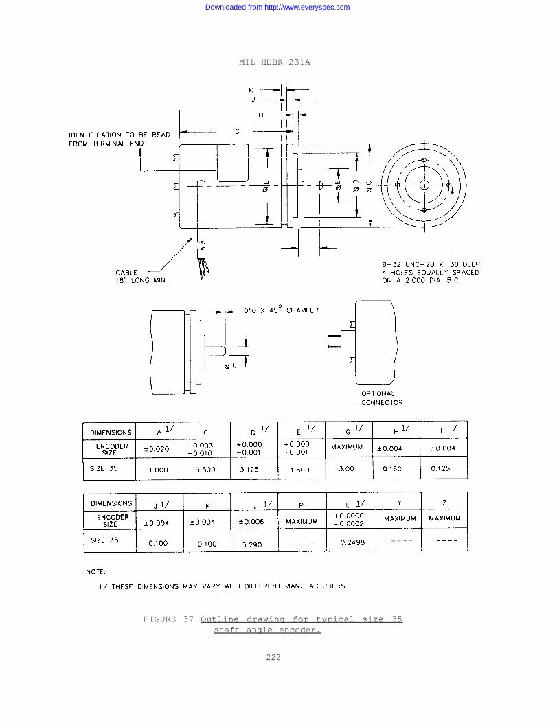
MIL-HDBK-231A
FIGURE 37 Outline drawing for typical size 35shaft angle encoder.
222
Downloaded from http://www.everyspec.com
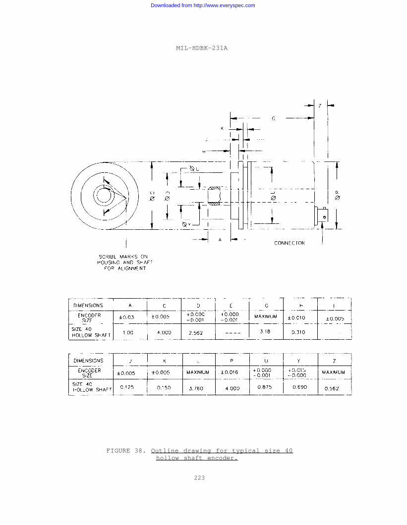
MIL-HDBK-231A
FIGURE 38. Outline drawing for typical size 40hollow shaft encoder.
223
Downloaded from http://www.everyspec.com
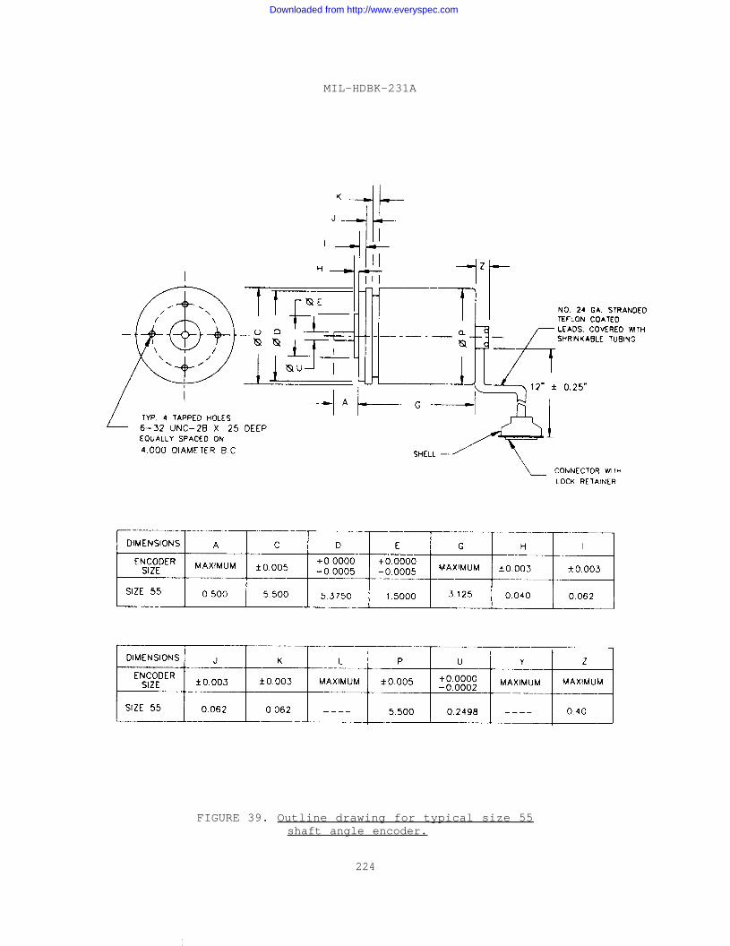
MIL-HDBK-231A
FIGURE 39. Outline drawing for typical size 55shaft angle encoder.
224
I
Downloaded from http://www.everyspec.com
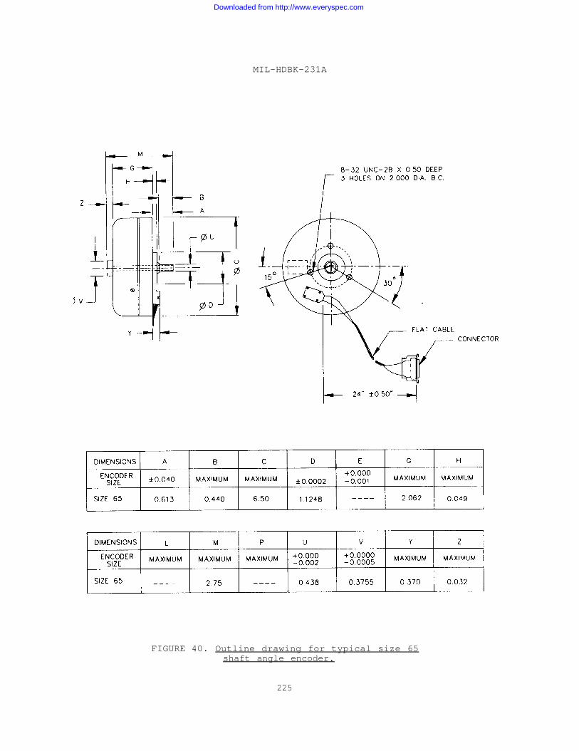
MIL-HDBK-231A
FIGURE 40. Outline drawing for typical size 65shaft angle encoder.
225
Downloaded from http://www.everyspec.com
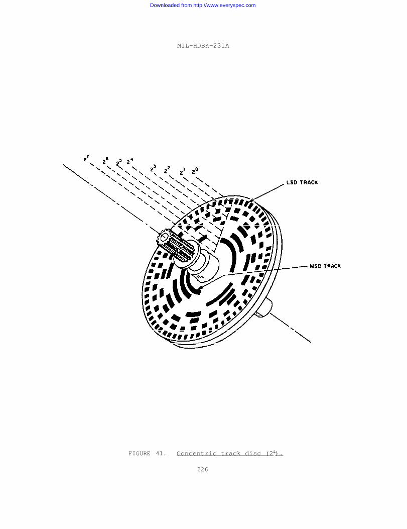
MIL-HDBK-231A
FIGURE 41. Concentric track disc (28).
226
Downloaded from http://www.everyspec.com
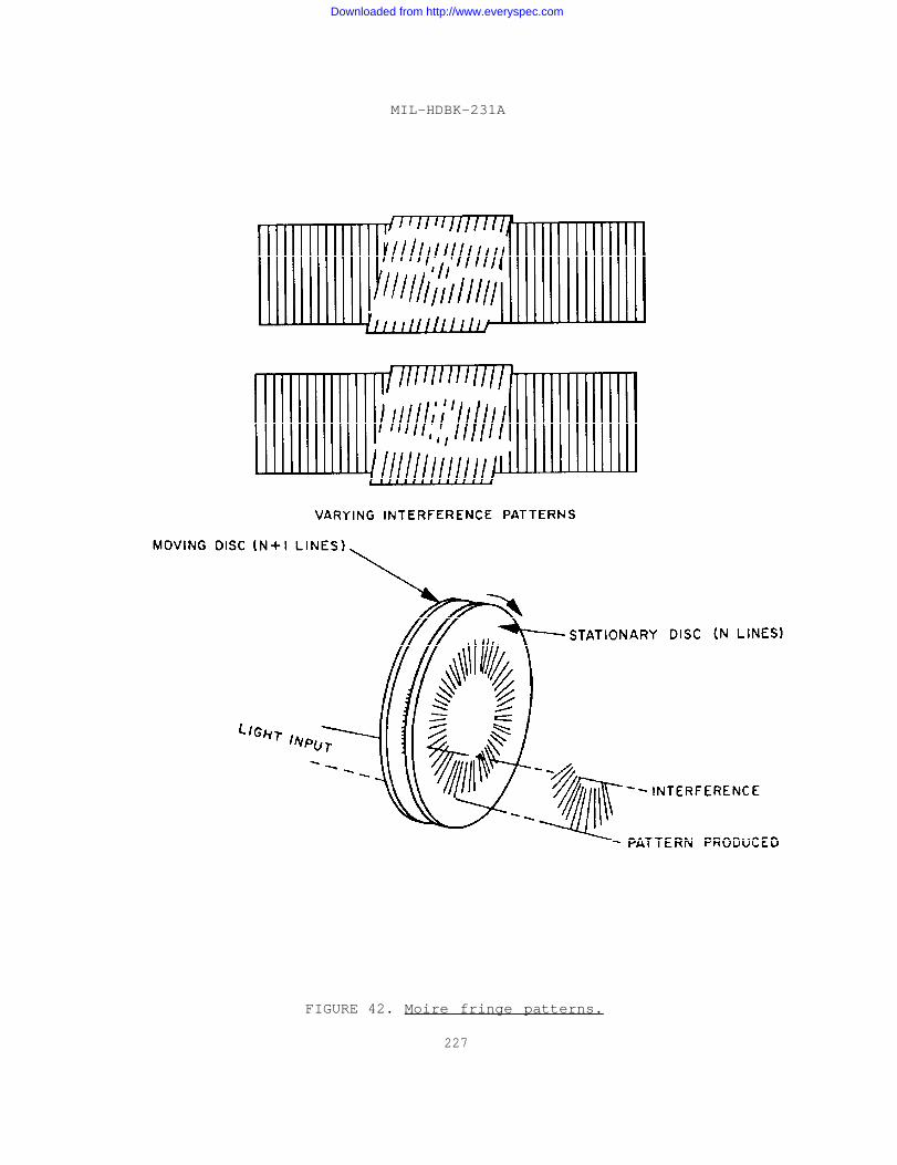
MIL-HDBK-231A
FIGURE 42. Moire fringe patterns.
227
Downloaded from http://www.everyspec.com
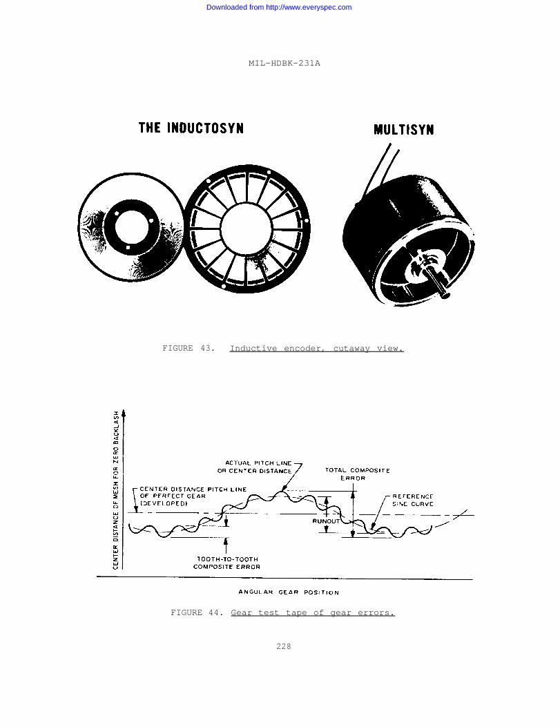
MIL-HDBK-231A
FIGURE 43. Inductive encoder, cutaway view.
FIGURE 44. Gear test tape of gear errors.
228
Downloaded from http://www.everyspec.com
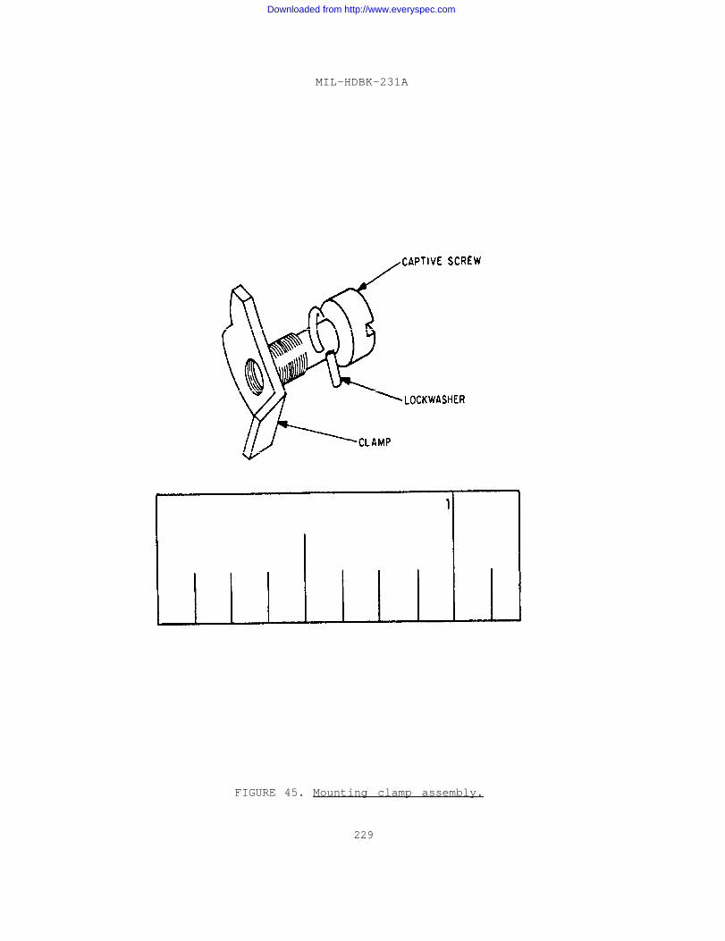
MIL-HDBK-231A
FIGURE 45. Mounting clamp assembly.
229
Downloaded from http://www.everyspec.com
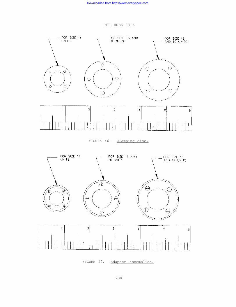
MIL-HDBK-231A
FIGURE 46. Clamping disc.
FIGURE 47. Adapter assemblies.
230
Downloaded from http://www.everyspec.com
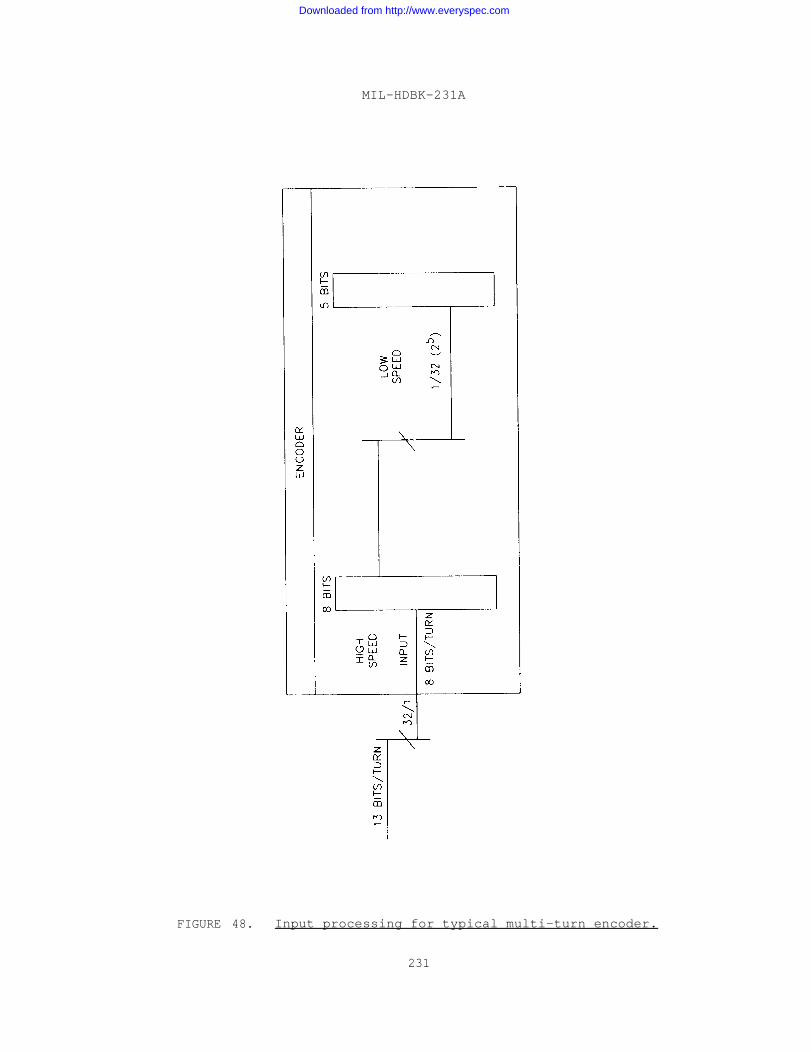
MIL-HDBK-231A
FIGURE 48. Input processing for typical multi-turn encoder.
231
Downloaded from http://www.everyspec.com
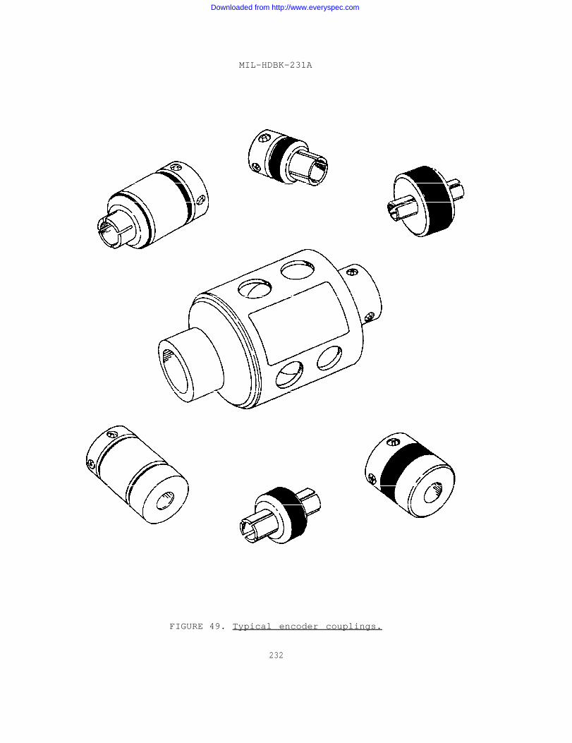
MIL-HDBK-231A
FIGURE 49. Typical encoder couplings.
232
Downloaded from http://www.everyspec.com
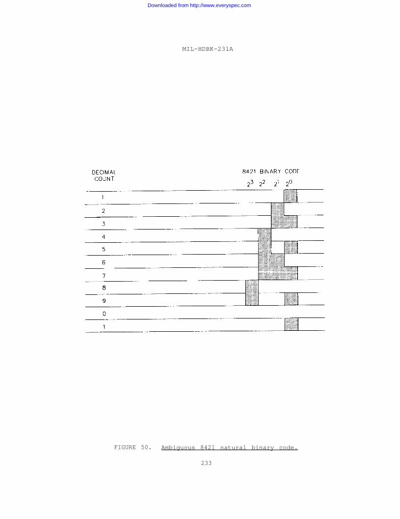
MIL-HDBK-231A
FIGURE 50. Ambiguous 8421 natural binary code.
233
Downloaded from http://www.everyspec.com
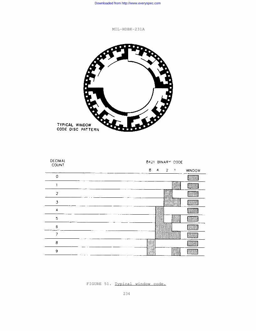
MIL-HDBK-231A
FIGURE 51. Typical window code.
234
Downloaded from http://www.everyspec.com
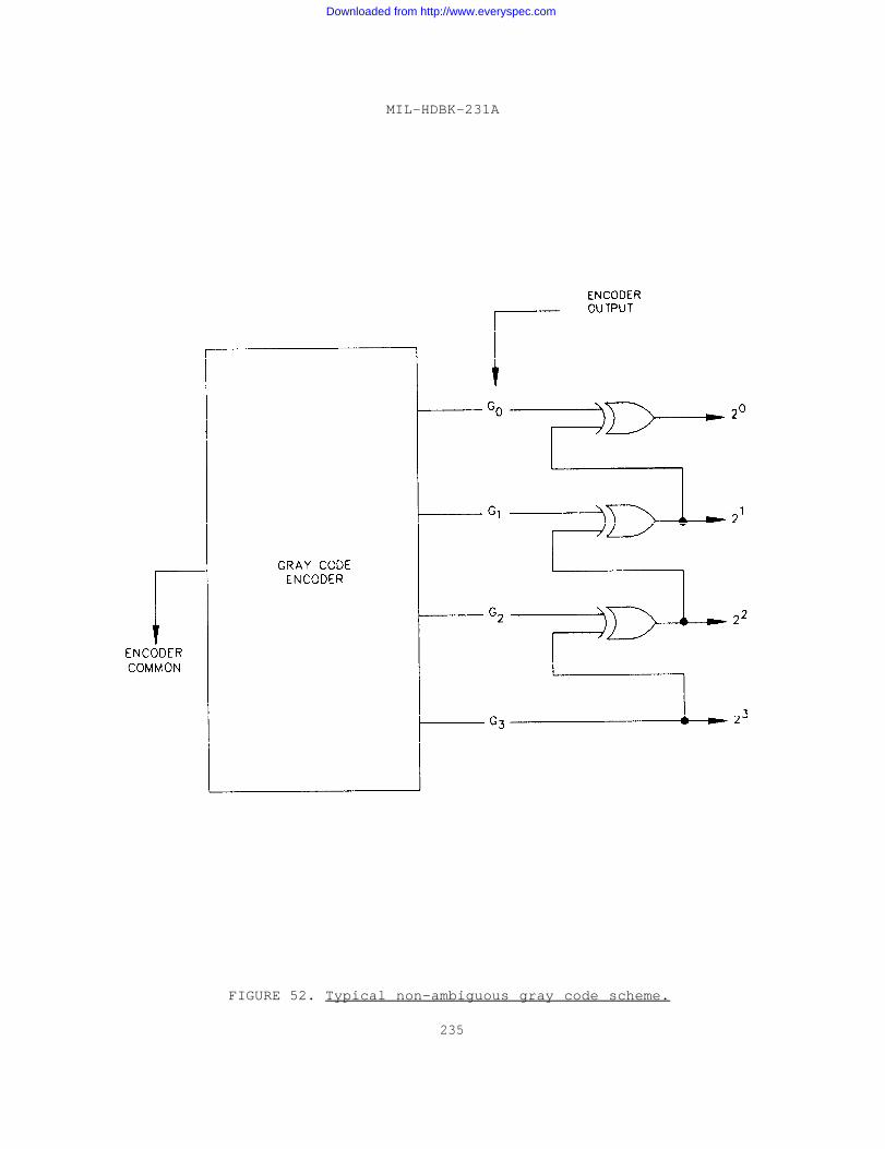
MIL-HDBK-231A
FIGURE 52. Typical non-ambiguous gray code scheme.
235
Downloaded from http://www.everyspec.com
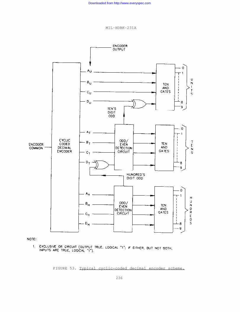
MIL-HDBK-231A
FIGURE 53. Typical cyclic-coded decimal encoder scheme.
236
Downloaded from http://www.everyspec.com
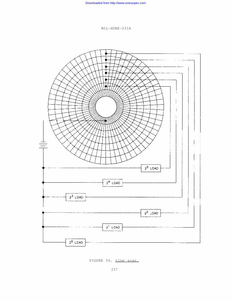
MIL-HDBK-231A
FIGURE 54. Line scan.
237
Downloaded from http://www.everyspec.com
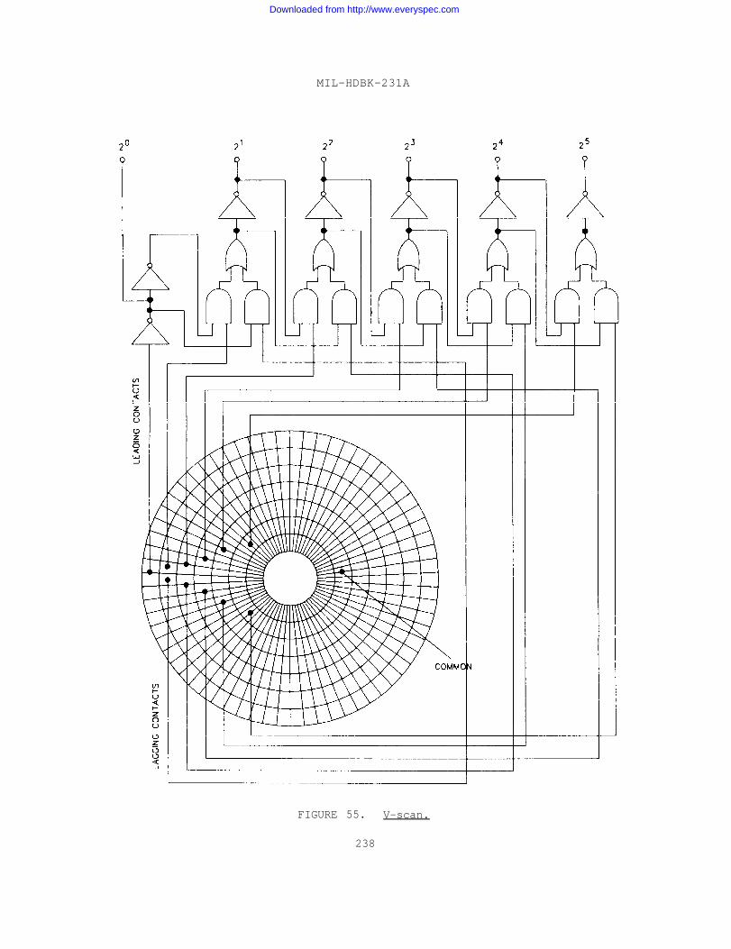
MIL-HDBK-231A
FIGURE 55. V-scan.
238
Downloaded from http://www.everyspec.com
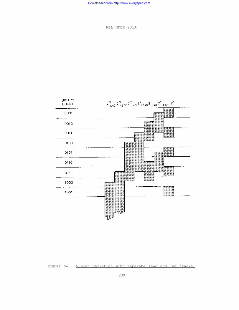
MIL-HDBK-231A
FIGURE 56. V-scan variation with separate lead and lag tracks.
239
Downloaded from http://www.everyspec.com
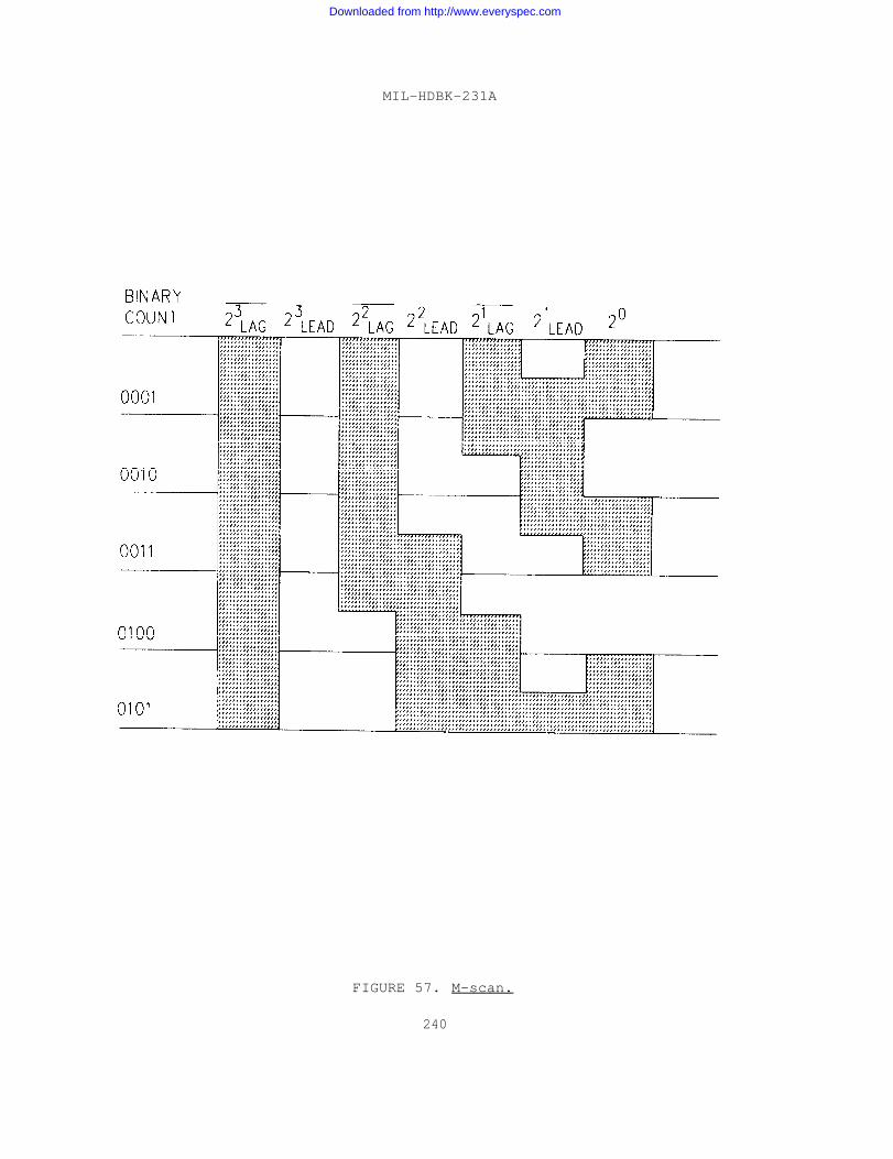
MIL-HDBK-231A
FIGURE 57. M-scan.
240
Downloaded from http://www.everyspec.com
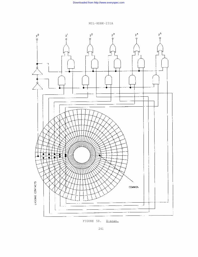
MIL-HDBK-231A
FIGURE 58. U-scan.
241
Downloaded from http://www.everyspec.com
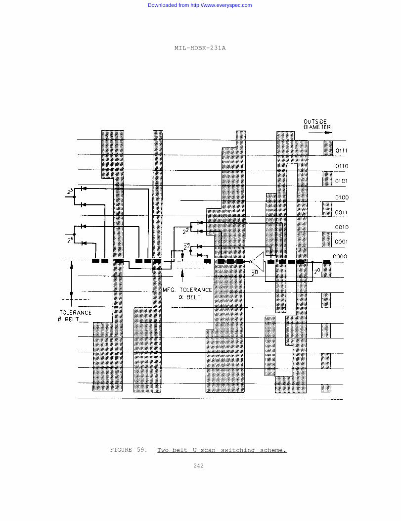
MIL-HDBK-231A
FIGURE 59. Two-belt U-scan switching scheme.
242
Downloaded from http://www.everyspec.com
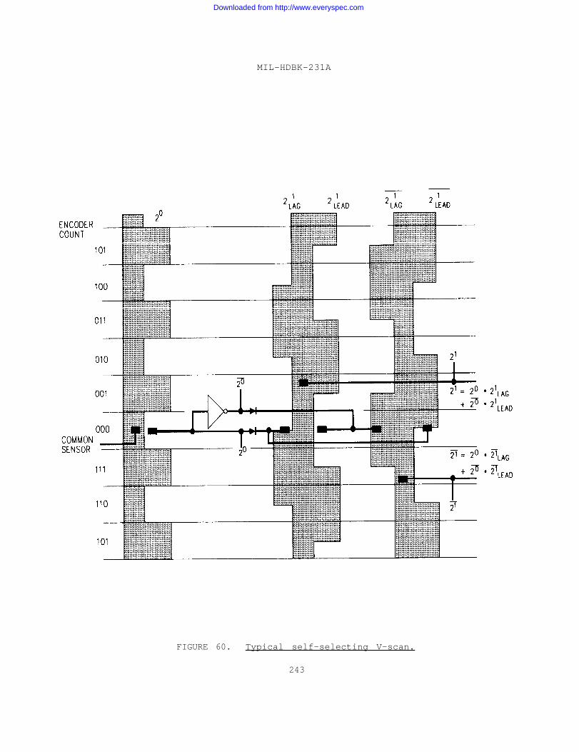
MIL-HDBK-231A
FIGURE 60. Typical self-selecting V-scan.
243
Downloaded from http://www.everyspec.com
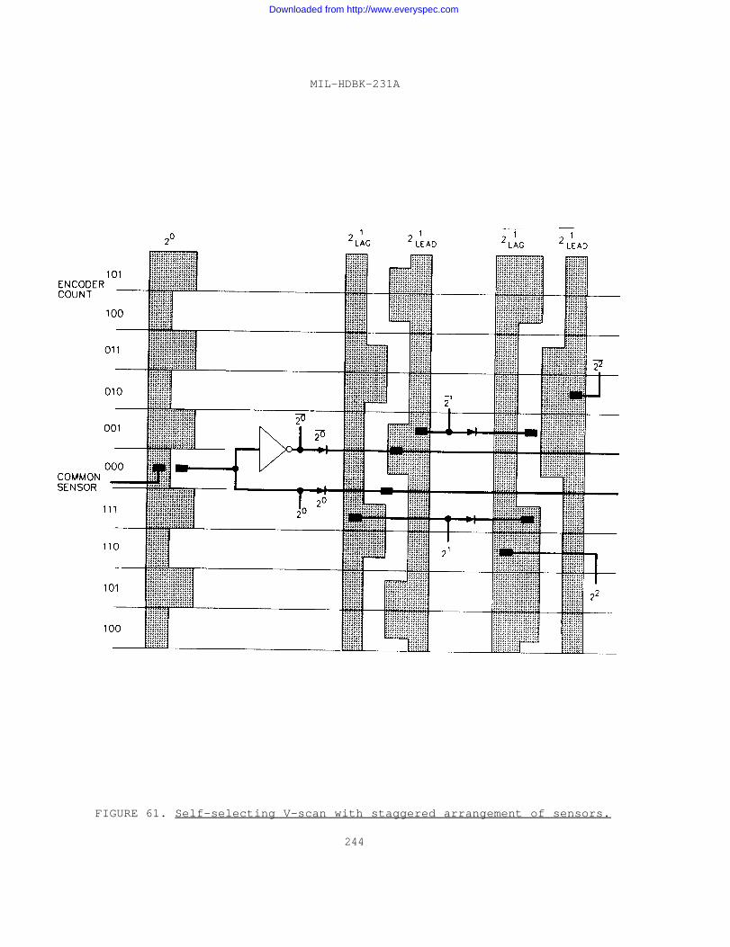
MIL-HDBK-231A
FIGURE 61. Self-selecting V-scan with staggered arrangement of sensors.
244
Downloaded from http://www.everyspec.com

MIL-HDBK-231A
FIGURE 62. Self-selecting U-scan.
245
Downloaded from http://www.everyspec.com

MIL-HDBK-231A
FIGURE 63. Typical logic scheme for a multi-turn encoder.
246
Downloaded from http://www.everyspec.com
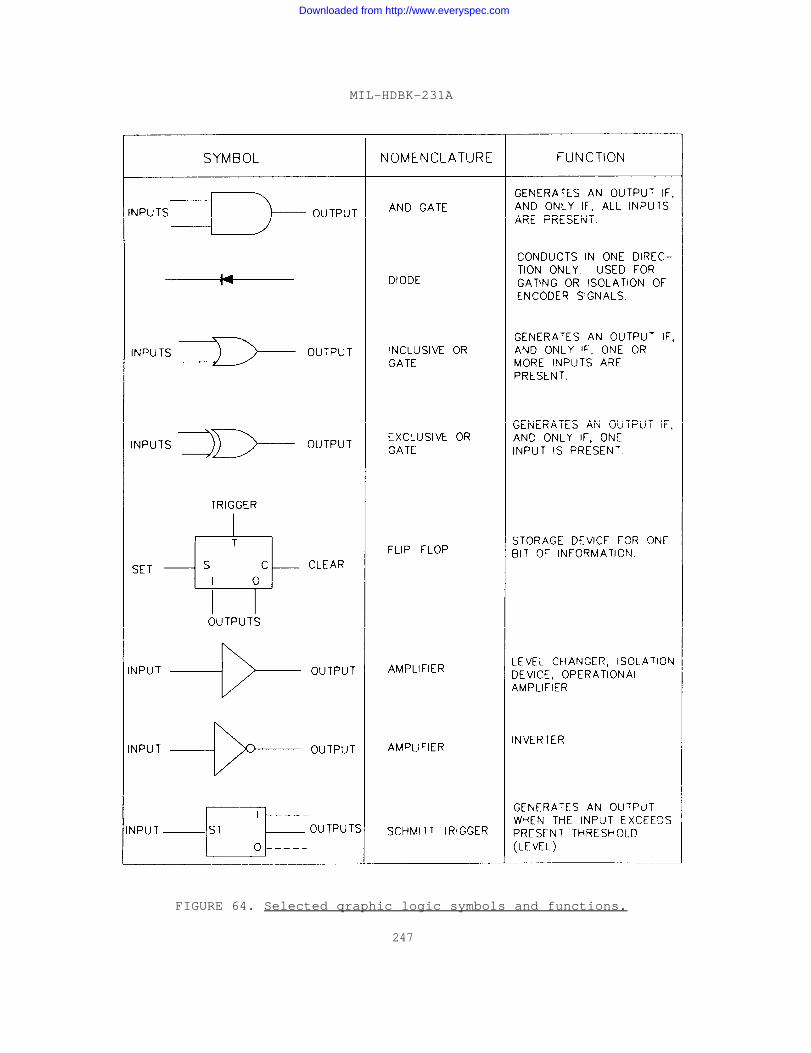
MIL-HDBK-231A
FIGURE 64. Selected qraphic logic symbols and functions.
247
Downloaded from http://www.everyspec.com
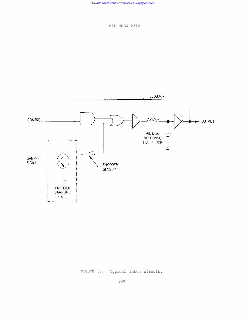
MIL-HDBK-231A
FIGURE 65. Typical latch circuit.
248
Downloaded from http://www.everyspec.com
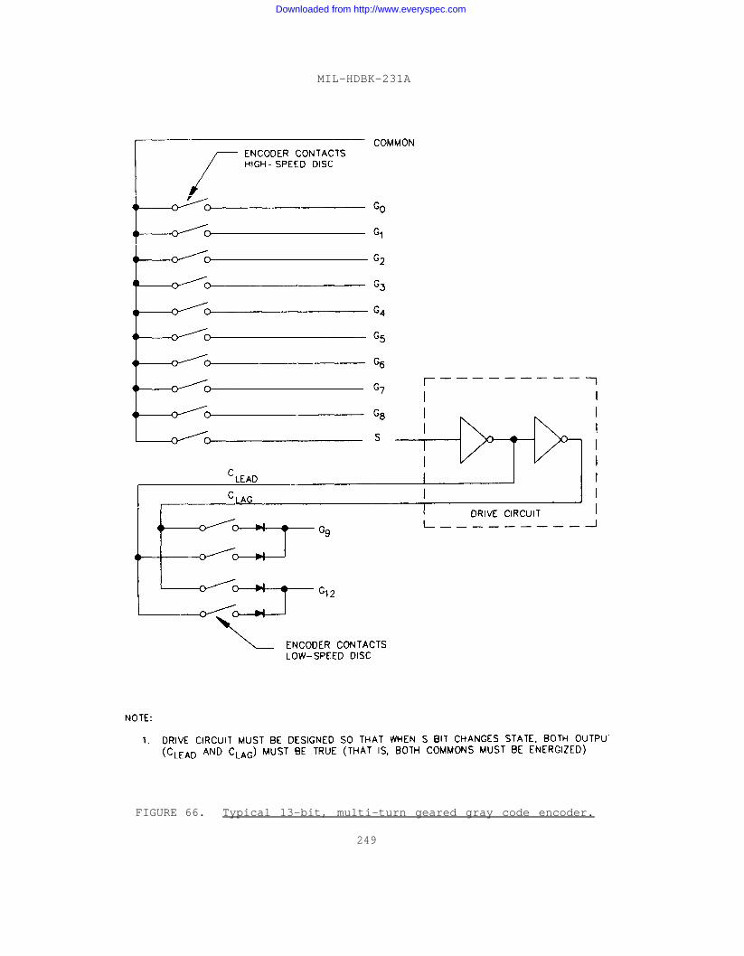
MIL-HDBK-231A
FIGURE 66. Typical 13-bit, multi-turn geared gray code encoder.
249
Downloaded from http://www.everyspec.com
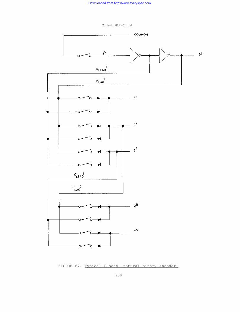
MIL-HDBK-231A
FIGURE 67. Typical U-scan, natural binary encoder.
250
Downloaded from http://www.everyspec.com
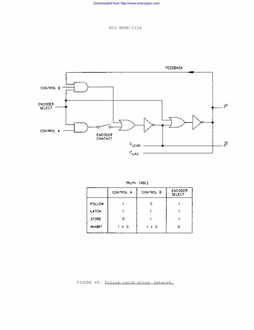
MIL-HDBK-231A
FIGURE 68. Follow-latch-store network.
Downloaded from http://www.everyspec.com
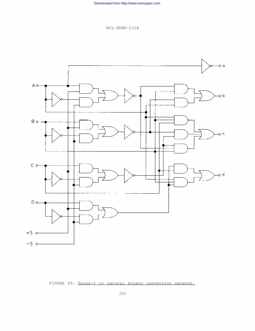
MIL-HDBK-231A
FIGURE 69. Excss-3 to natural binary conversion network.
252
Downloaded from http://www.everyspec.com
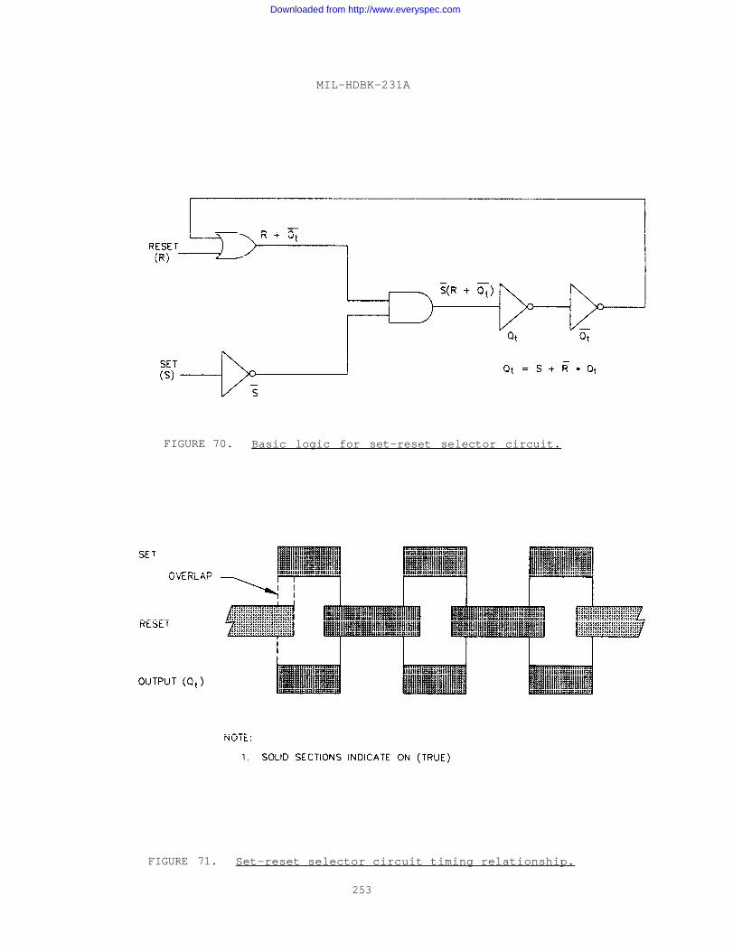
MIL-HDBK-231A
FIGURE 70. Basic logic for set-reset selector circuit.
FIGURE 71. Set-reset selector circuit timing relationship.
253
Downloaded from http://www.everyspec.com
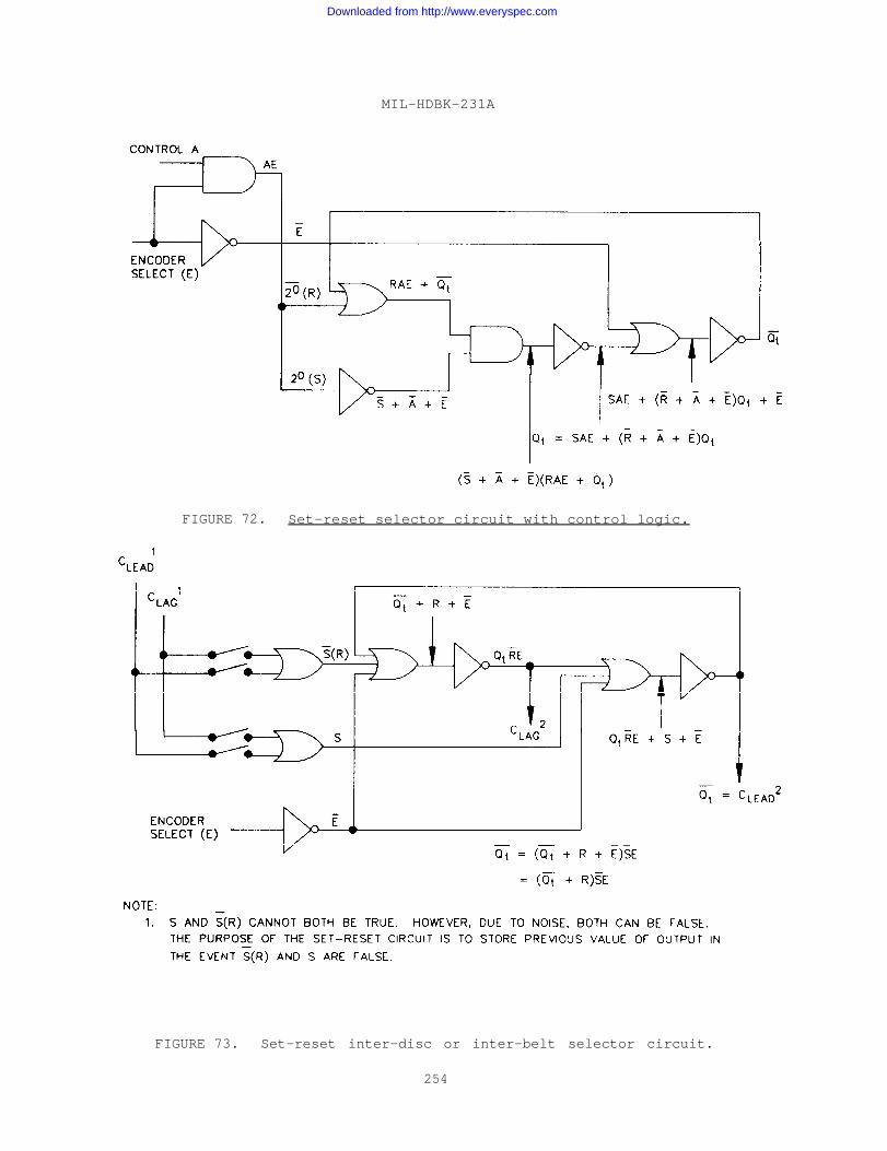
MIL-HDBK-231A
FIGURE 72. Set-reset selector circuit with control logic.
FIGURE 73. Set-reset inter-disc or inter-belt selector circuit.
254
Downloaded from http://www.everyspec.com
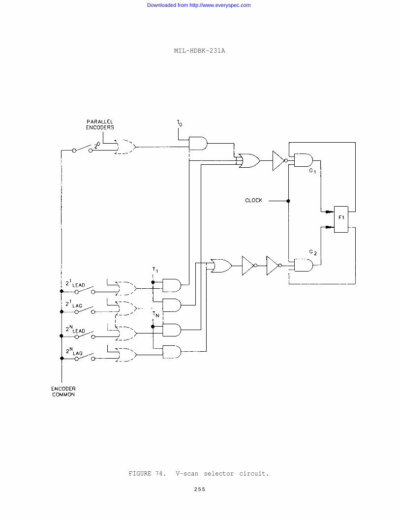
MIL-HDBK-231A
FIGURE 74. V-scan selector circuit.
2 5 5
Downloaded from http://www.everyspec.com
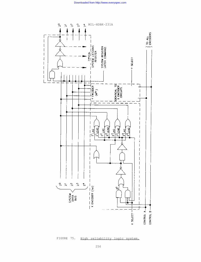
MIL-HDBK-231A
FIGURE 75. High reliability logic system.
256
Downloaded from http://www.everyspec.com
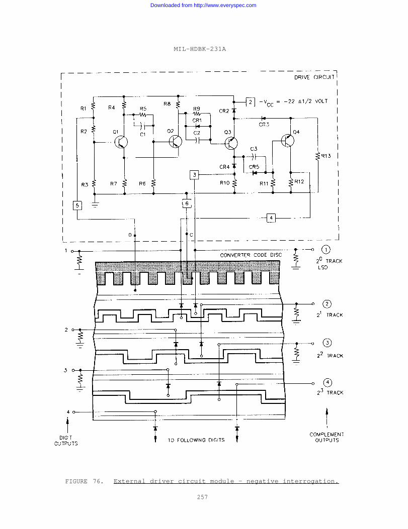
MIL-HDBK-231A
FIGURE 76. External driver circuit module - negative interrogation.
257
Downloaded from http://www.everyspec.com
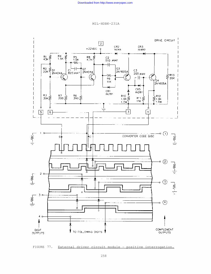
MIL-HDBK-231A
FIGURE 77. External driver circuit module - positive interrogation.
258
Downloaded from http://www.everyspec.com
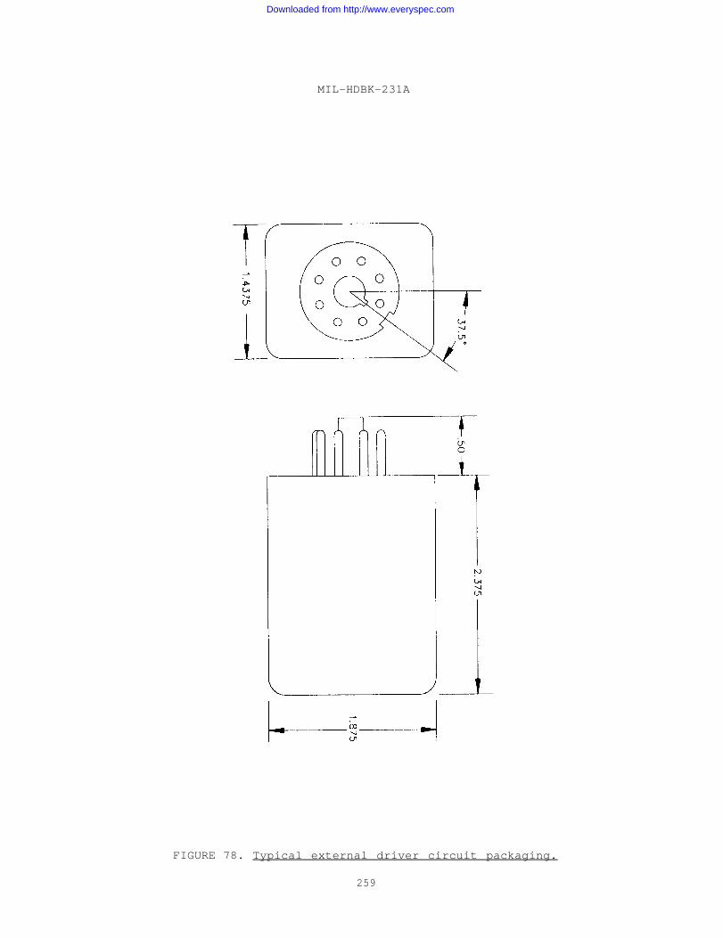
MIL-HDBK-231A
FIGURE 78. Typical external driver circuit packaging.
259
Downloaded from http://www.everyspec.com
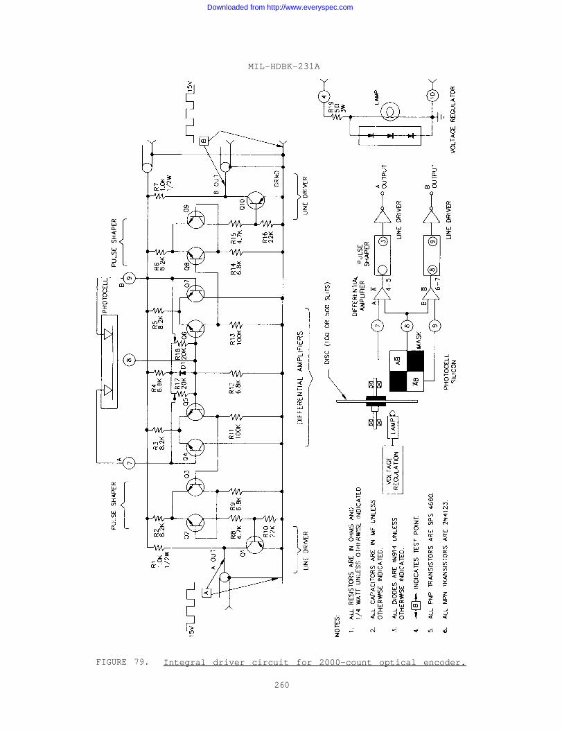
MIL-HDBK-231A
FIGURE 79. Integral driver circuit for 2000-count optical encoder.
260
Downloaded from http://www.everyspec.com
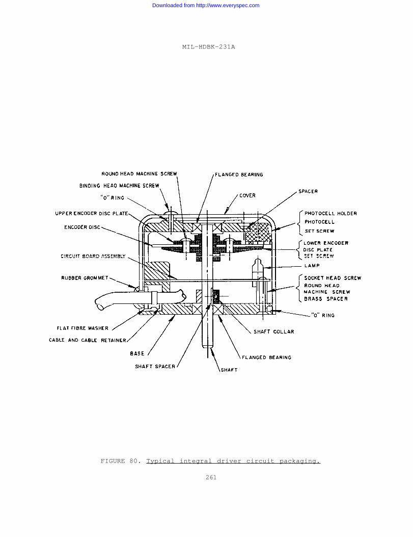
MIL-HDBK-231A
FIGURE 80. Typical integral driver circuit packaging.
261
Downloaded from http://www.everyspec.com
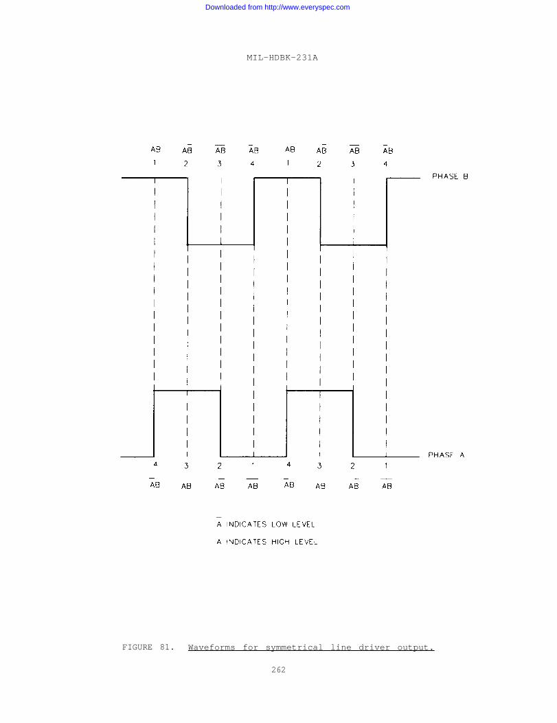
MIL-HDBK-231A
FIGURE 81. Waveforms for symmetrical line driver output.
262
Downloaded from http://www.everyspec.com
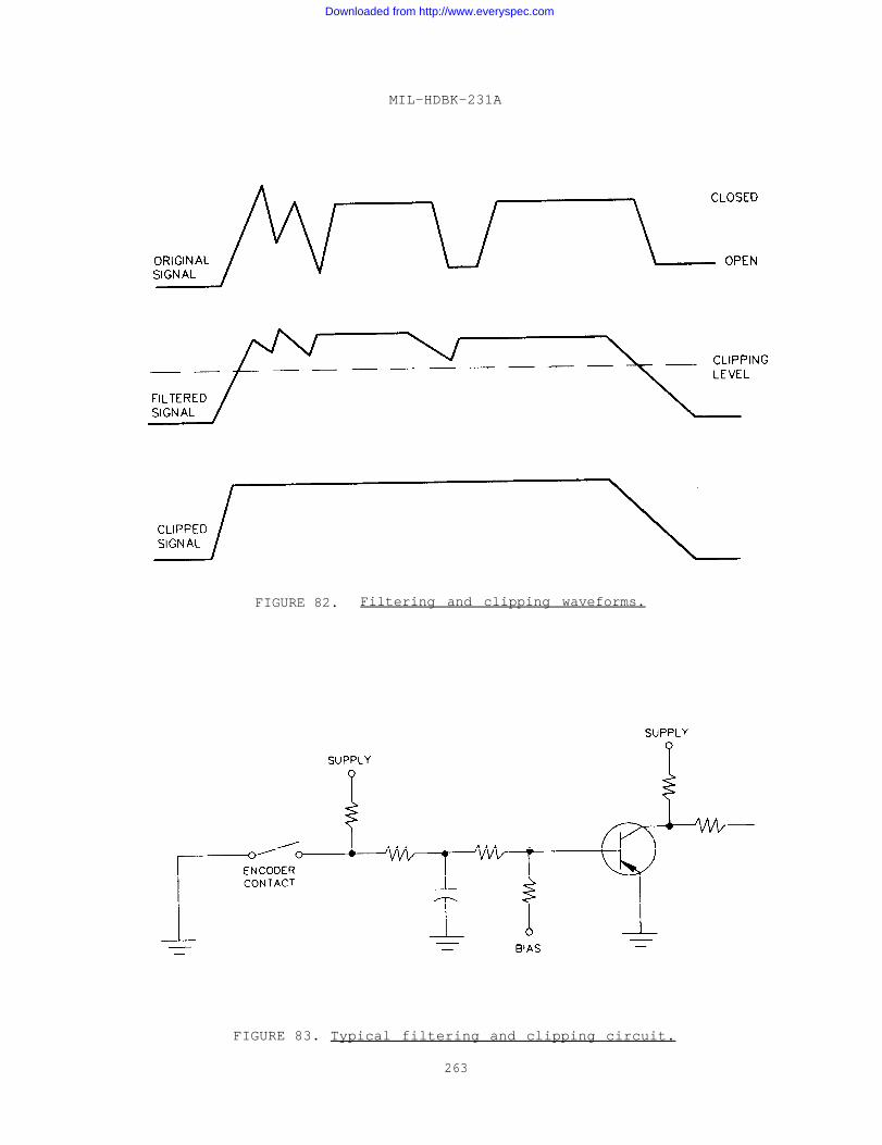
MIL-HDBK-231A
FIGURE 82. Filtering and clipping waveforms.
FIGURE 83. Typical filtering and clipping circuit.
263
Downloaded from http://www.everyspec.com
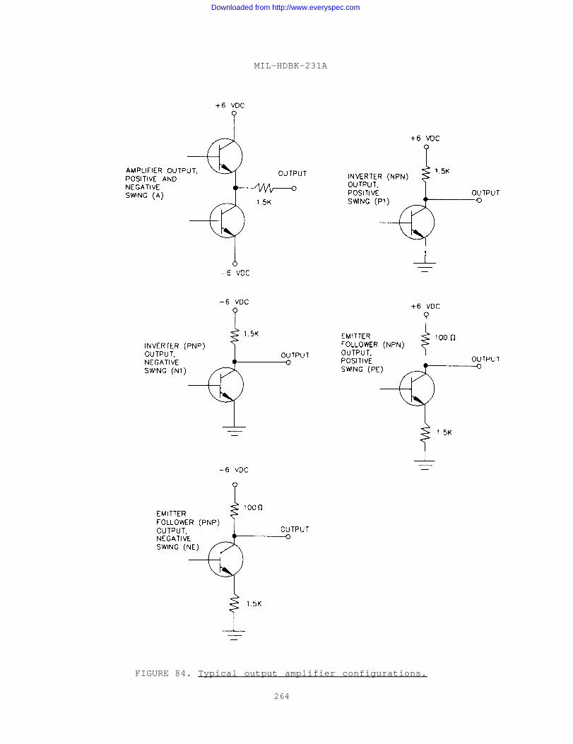
MIL-HDBK-231A
FIGURE 84. Typical output amplifier configurations.
264
Downloaded from http://www.everyspec.com
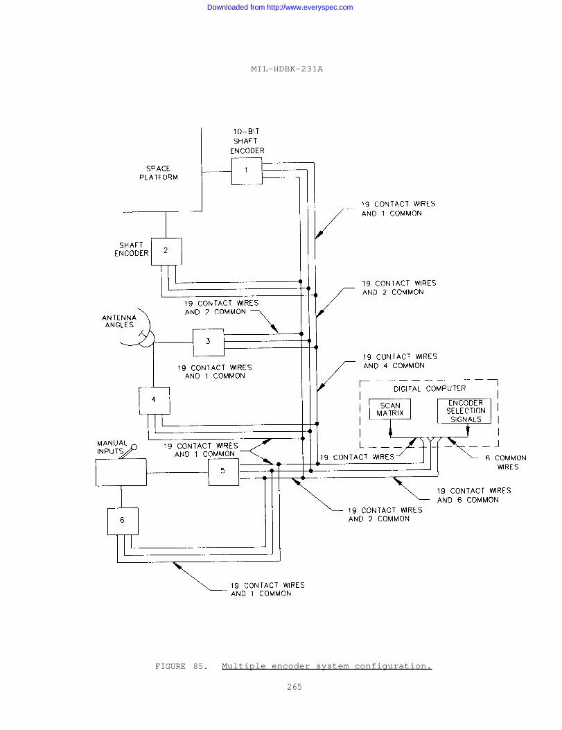
MIL-HDBK-231A
FIGURE 85. Multiple encoder system configuration.
265
Downloaded from http://www.everyspec.com
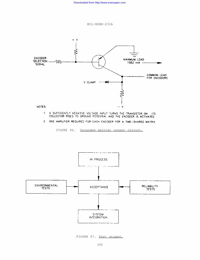
MIL-HDBK-231A
FIGURE 86. Grounded emitter output circuit.
FIGURE 87. Test stages.
266
Downloaded from http://www.everyspec.com
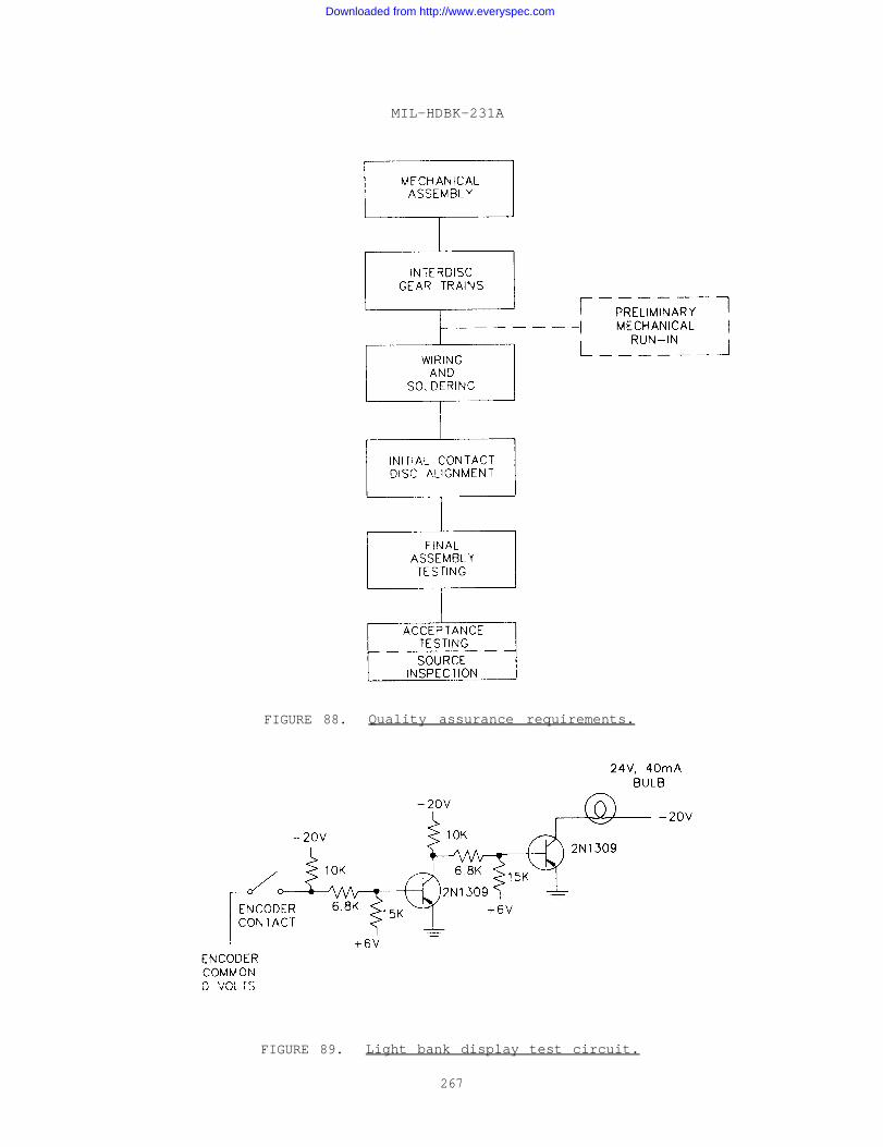
MIL-HDBK-231A
FIGURE 88. Quality assurance requirements.
FIGURE 89. Light bank display test circuit.
267
Downloaded from http://www.everyspec.com
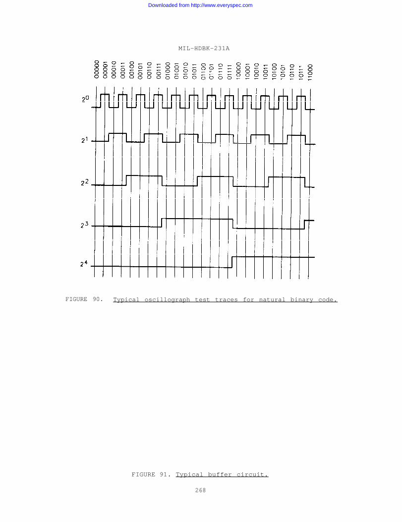
MIL-HDBK-231A
FIGURE 90. Typical oscillograph test traces for natural binary code.
FIGURE 91. Typical buffer circuit.
268
Downloaded from http://www.everyspec.com
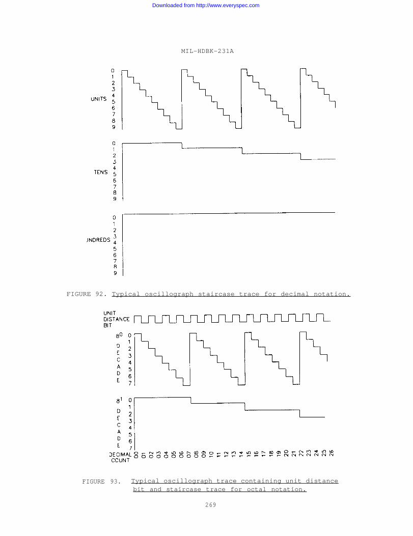
MIL-HDBK-231A
FIGURE 92. Typical oscillograph staircase trace for decimal notation.
FIGURE 93. Typical oscillograph trace containing unit distancebit and staircase trace for octal notation.
269
Downloaded from http://www.everyspec.com
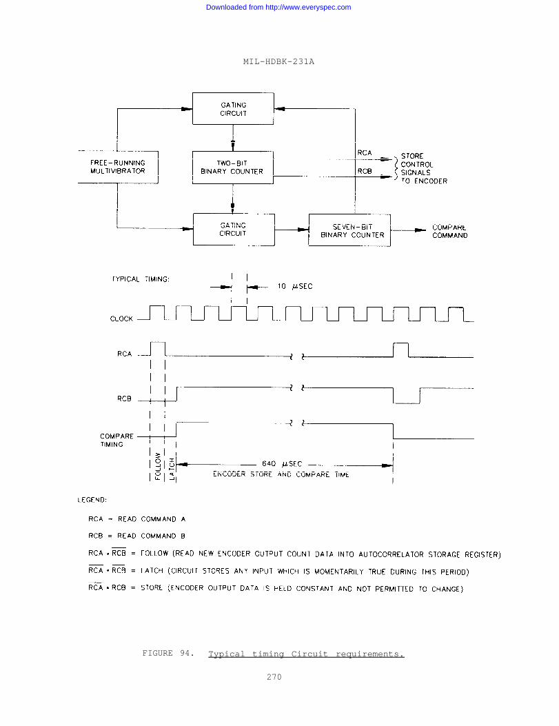
MIL-HDBK-231A
FIGURE 94. Typical timing Circuit requirements.
270
Downloaded from http://www.everyspec.com
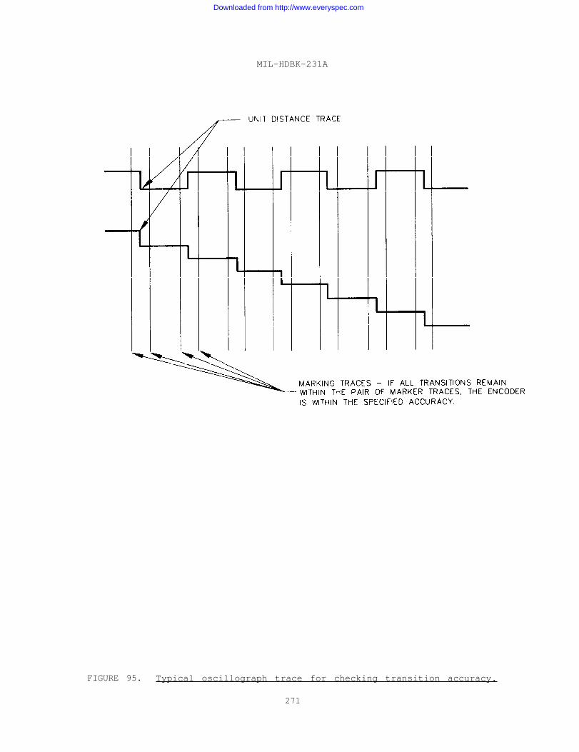
MIL-HDBK-231A
FIGURE 95. Typical oscillograph trace for checking transition accuracy.
271
Downloaded from http://www.everyspec.com
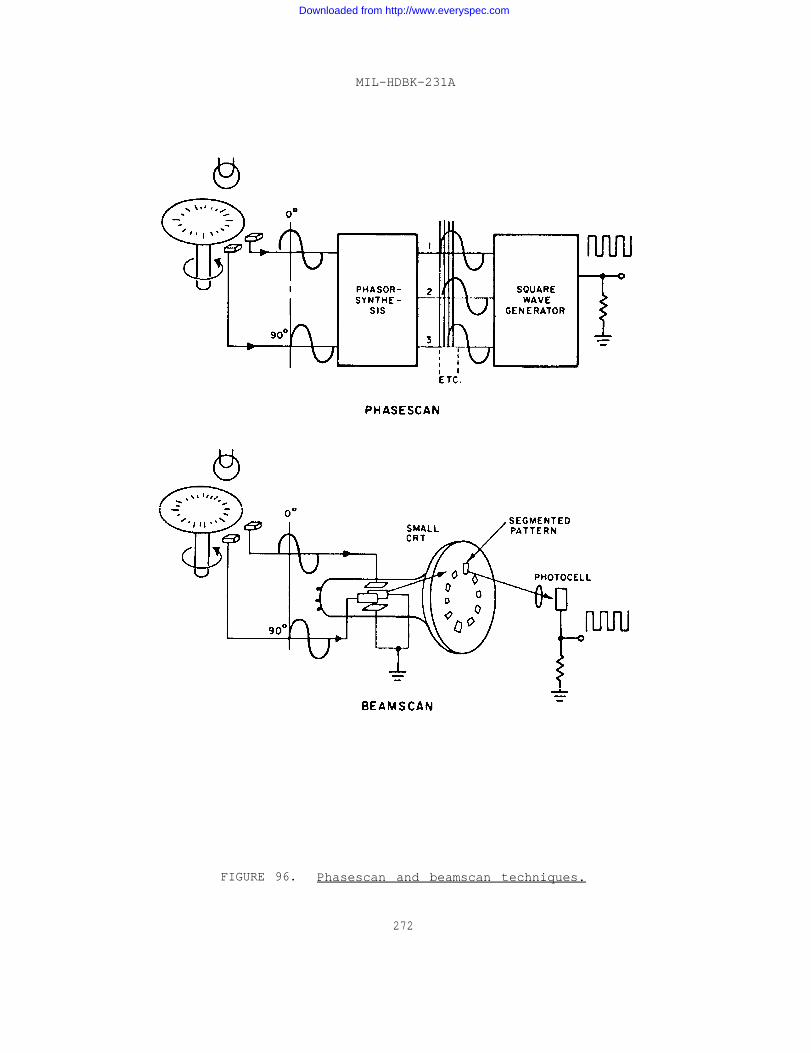
MIL-HDBK-231A
FIGURE 96. Phasescan and beamscan techniques.
272
Downloaded from http://www.everyspec.com
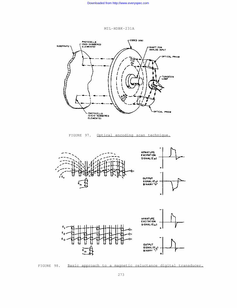
MIL-HDBK-231A
FIGURE 97. Optical encoding scan technique.
FIGURE 98. Basic approach to a magnetic reluctance digital transducer.
273
Downloaded from http://www.everyspec.com
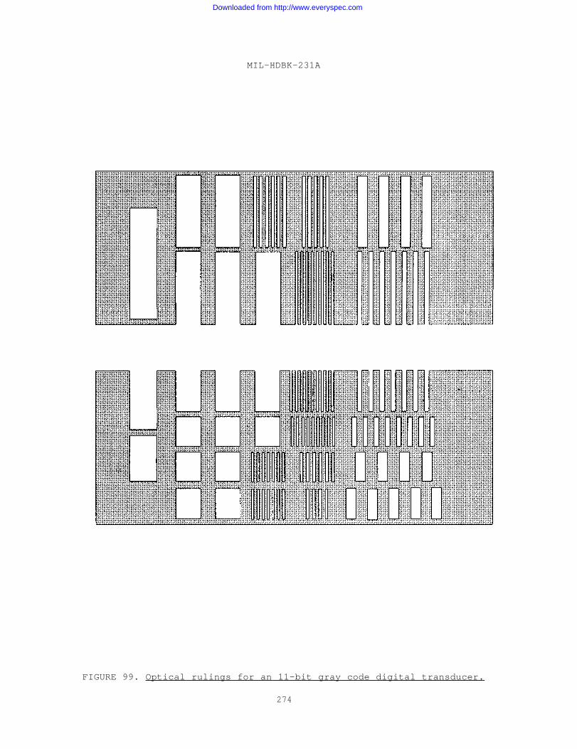
MIL-HDBK-231A
FIGURE 99. Optical rulings for an 11-bit gray code digital transducer.
274
Downloaded from http://www.everyspec.com
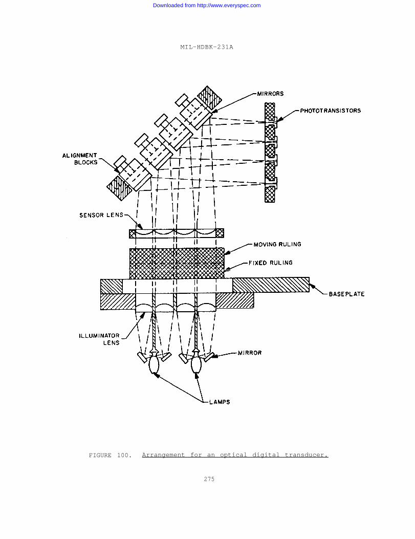
MIL-HDBK-231A
FIGURE 100. Arrangement for an optical digital transducer.
275
Downloaded from http://www.everyspec.com
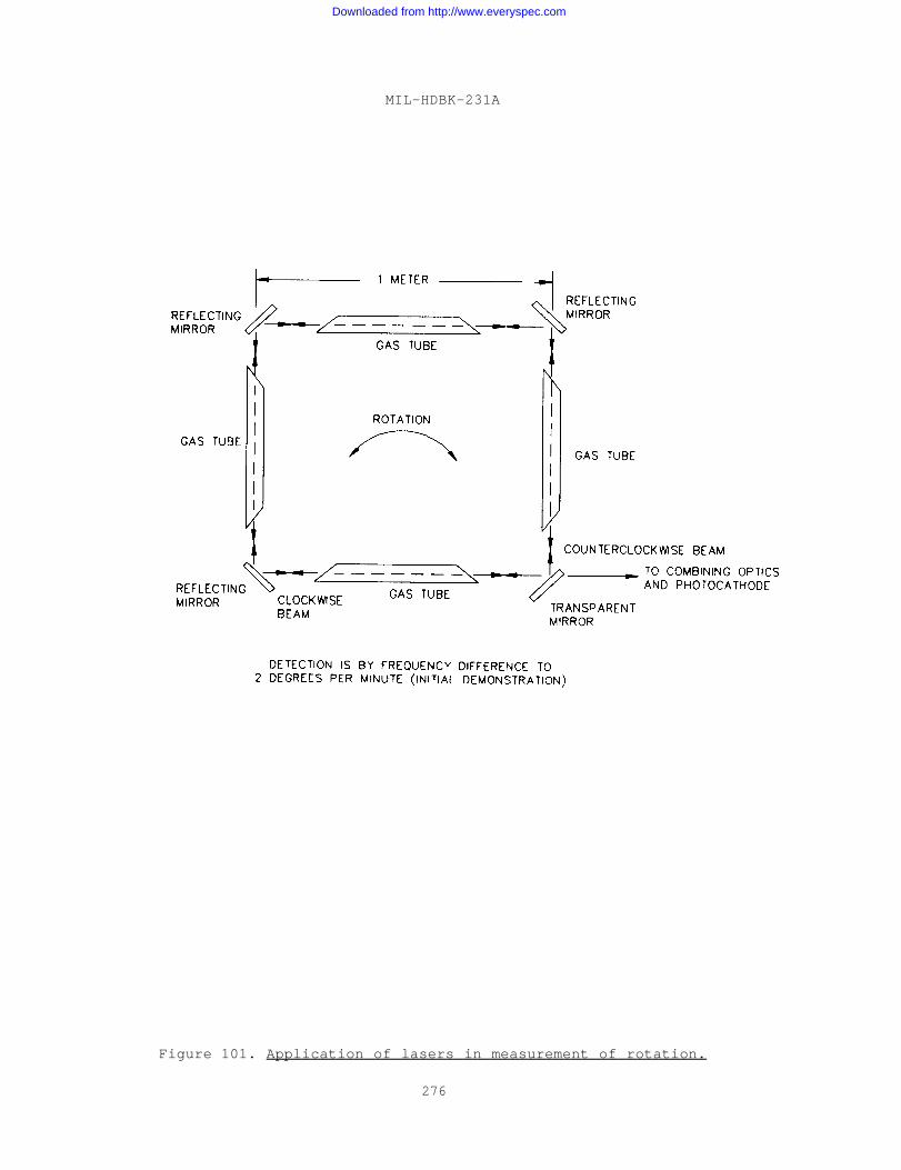
MIL-HDBK-231A
Figure 101. Application of lasers in measurement of rotation.
276
Downloaded from http://www.everyspec.com
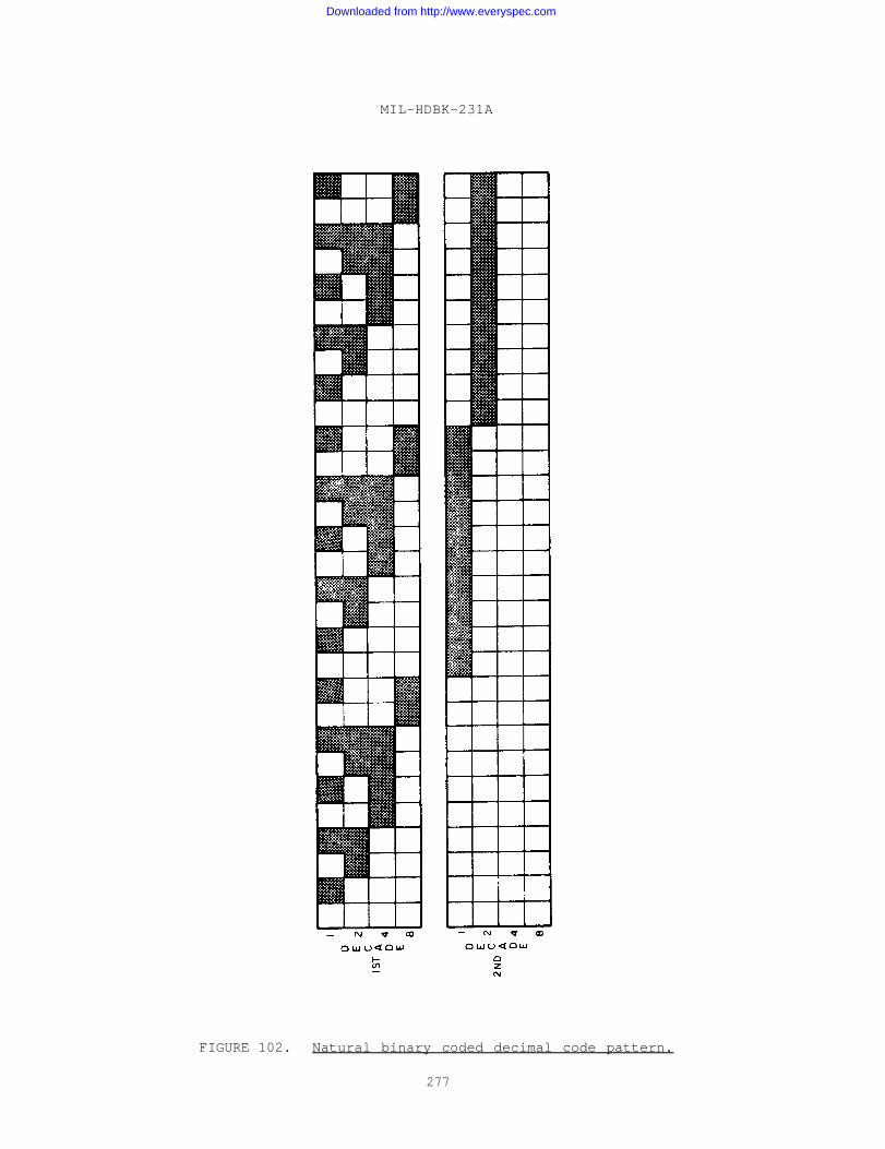
MIL-HDBK-231A
FIGURE 102. Natural binary coded decimal code pattern.
277
Downloaded from http://www.everyspec.com
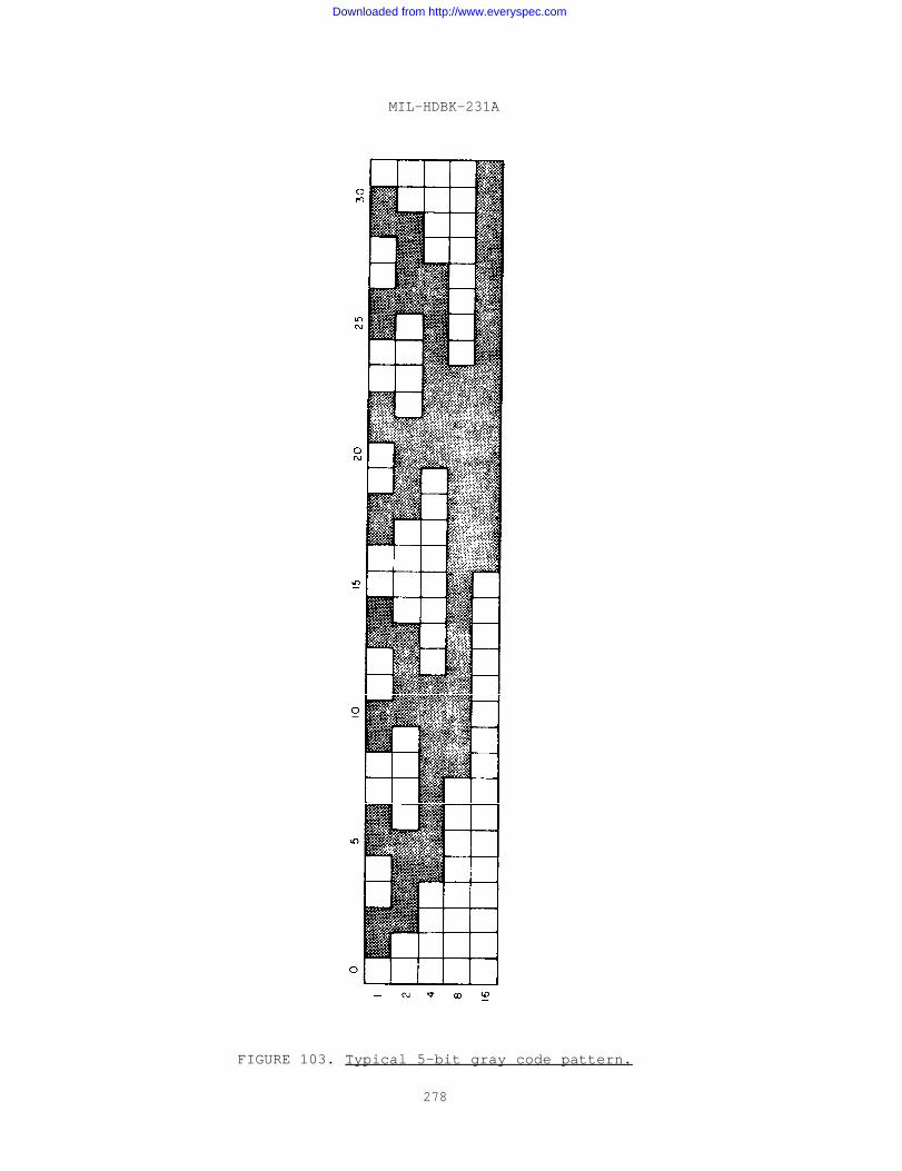
MIL-HDBK-231A
FIGURE 103. Typical 5-bit gray code pattern.
278
Downloaded from http://www.everyspec.com
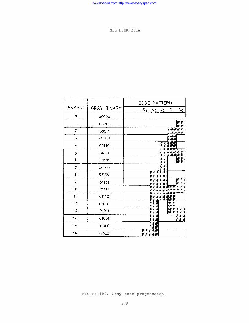
MIL-HDBK-231A
FIGURE 104. Gray code progression.
279
Downloaded from http://www.everyspec.com
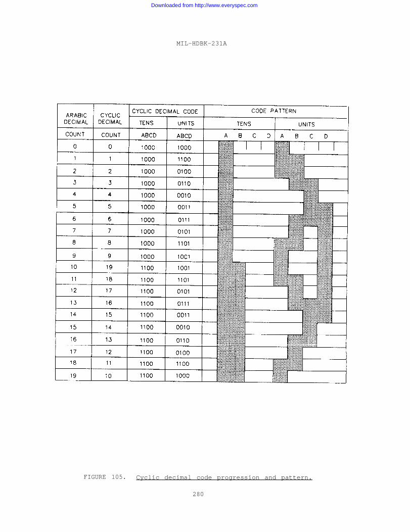
MIL-HDBK-231A
FIGURE 105. Cyclic decimal code progression and pattern.
280
Downloaded from http://www.everyspec.com
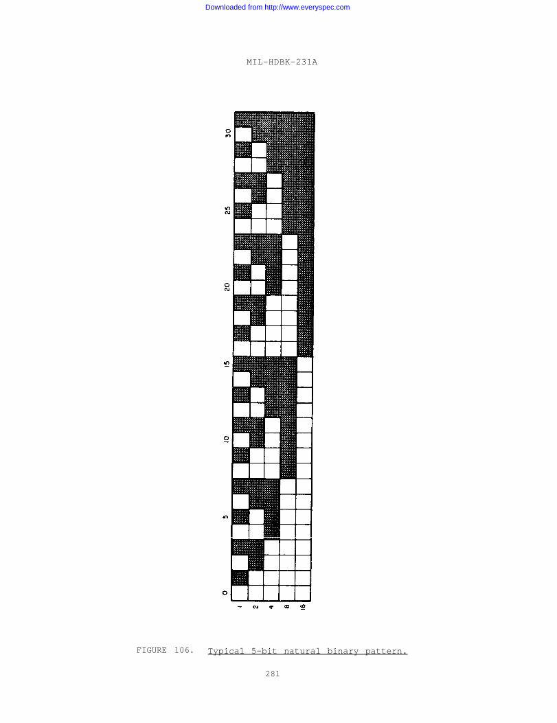
MIL-HDBK-231A
FIGURE 106. Typical 5-bit natural binary pattern.
281
Downloaded from http://www.everyspec.com
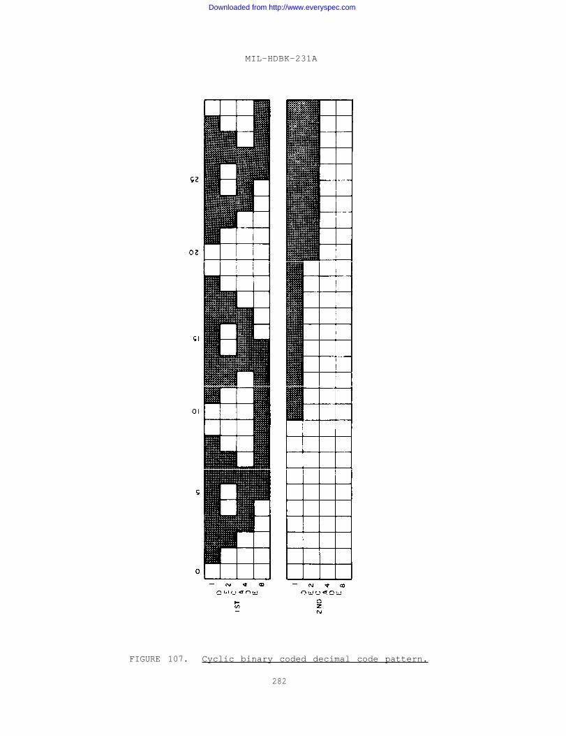
MIL-HDBK-231A
FIGURE 107. Cyclic binary coded decimal code pattern.
282
Downloaded from http://www.everyspec.com
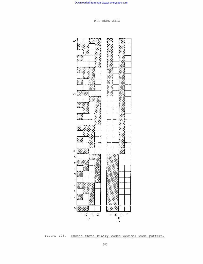
MIL-HDBK-231A
FIGURE 108. Excess three binary coded decimal code pattern.
283
Downloaded from http://www.everyspec.com

Downloaded from http://www.everyspec.com

Downloaded from http://www.everyspec.com
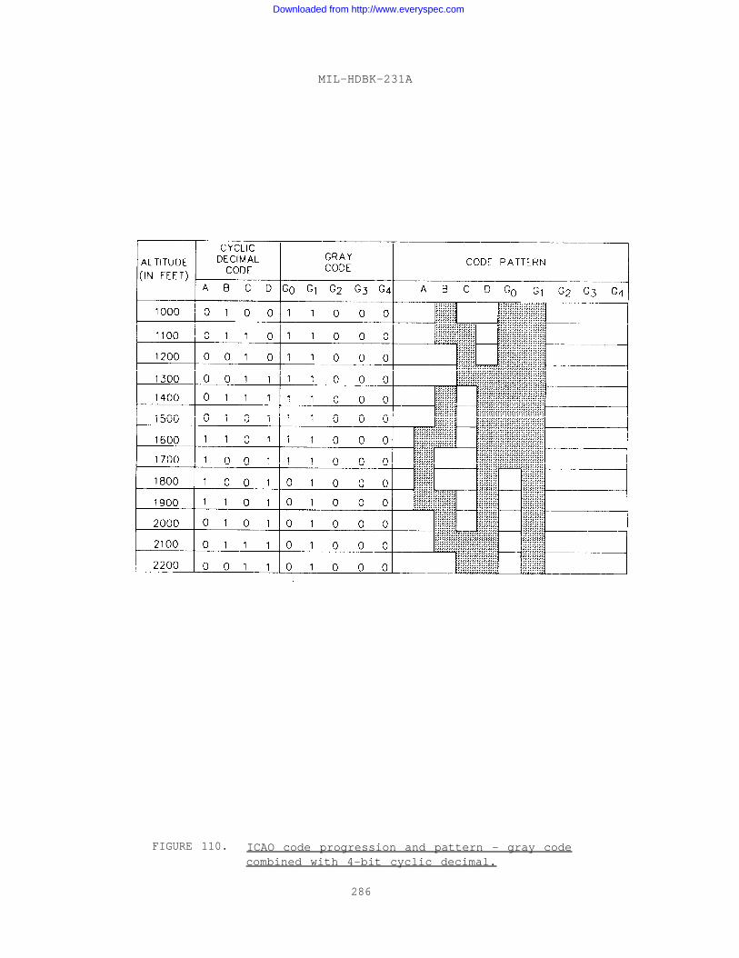
MIL-HDBK-231A
FIGURE 110. ICAO code progression and pattern - gray codecombined with 4-bit cyclic decimal.
286
Downloaded from http://www.everyspec.com
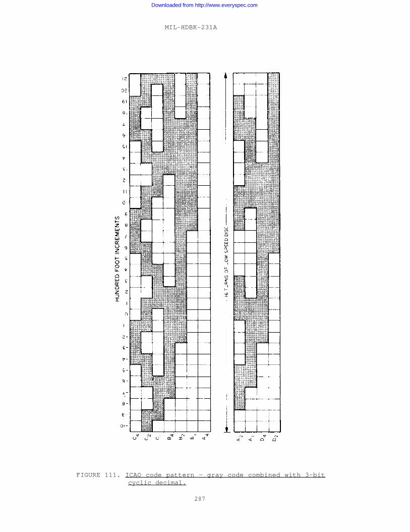
MIL-HDBK-231A
FIGURE 111. ICAO code pattern - gray code combined with 3-bitcyclic decimal.
287
Downloaded from http://www.everyspec.com

Downloaded from http://www.everyspec.com

Downloaded from http://www.everyspec.com
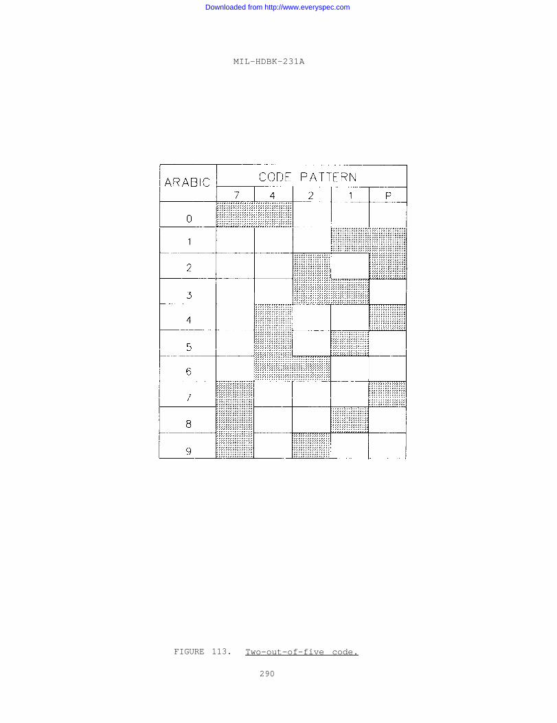
MIL-HDBK-231A
FIGURE 113. Two-out-of-five code.
290
Downloaded from http://www.everyspec.com
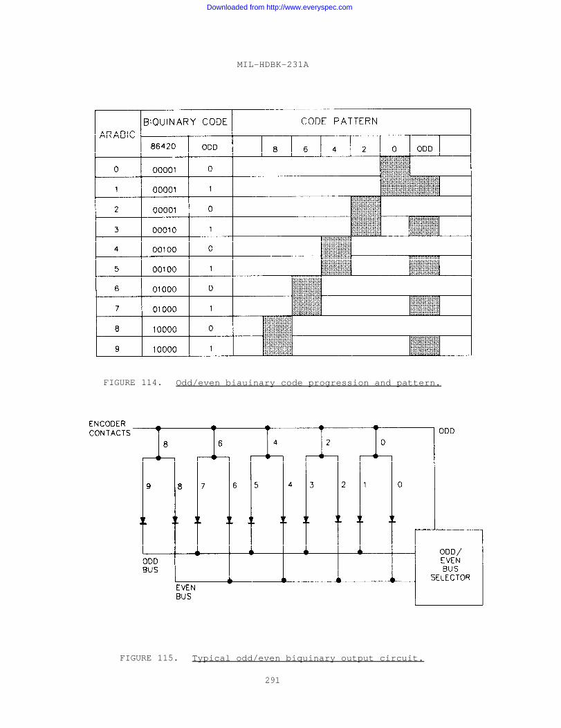
MIL-HDBK-231A
FIGURE 114. Odd/even biauinary code progression and pattern.
FIGURE 115. Typical odd/even biquinary output circuit.
291
Downloaded from http://www.everyspec.com
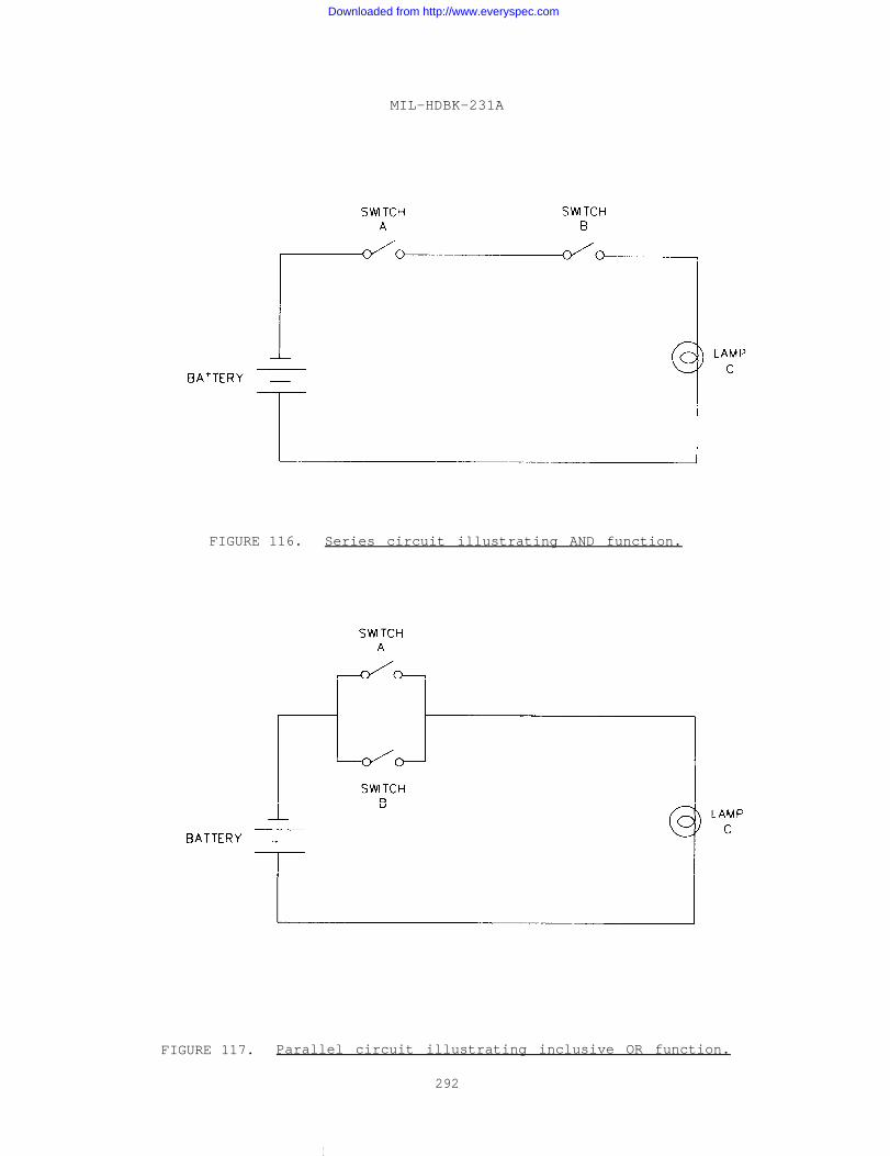
MIL-HDBK-231A
FIGURE 116. Series circuit illustrating AND function.
FIGURE 117. Parallel circuit illustrating inclusive OR function.
292
I
Downloaded from http://www.everyspec.com
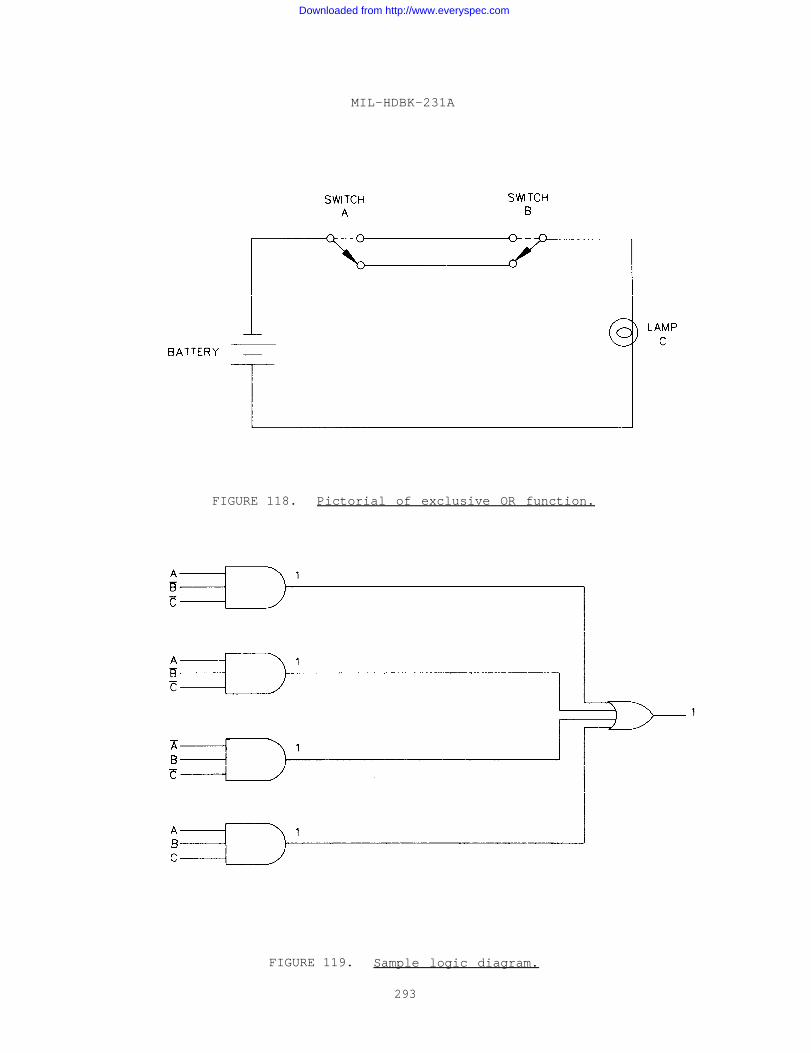
MIL-HDBK-231A
FIGURE 118. Pictorial of exclusive OR function.
FIGURE 119. Sample logic diagram.
293
Downloaded from http://www.everyspec.com
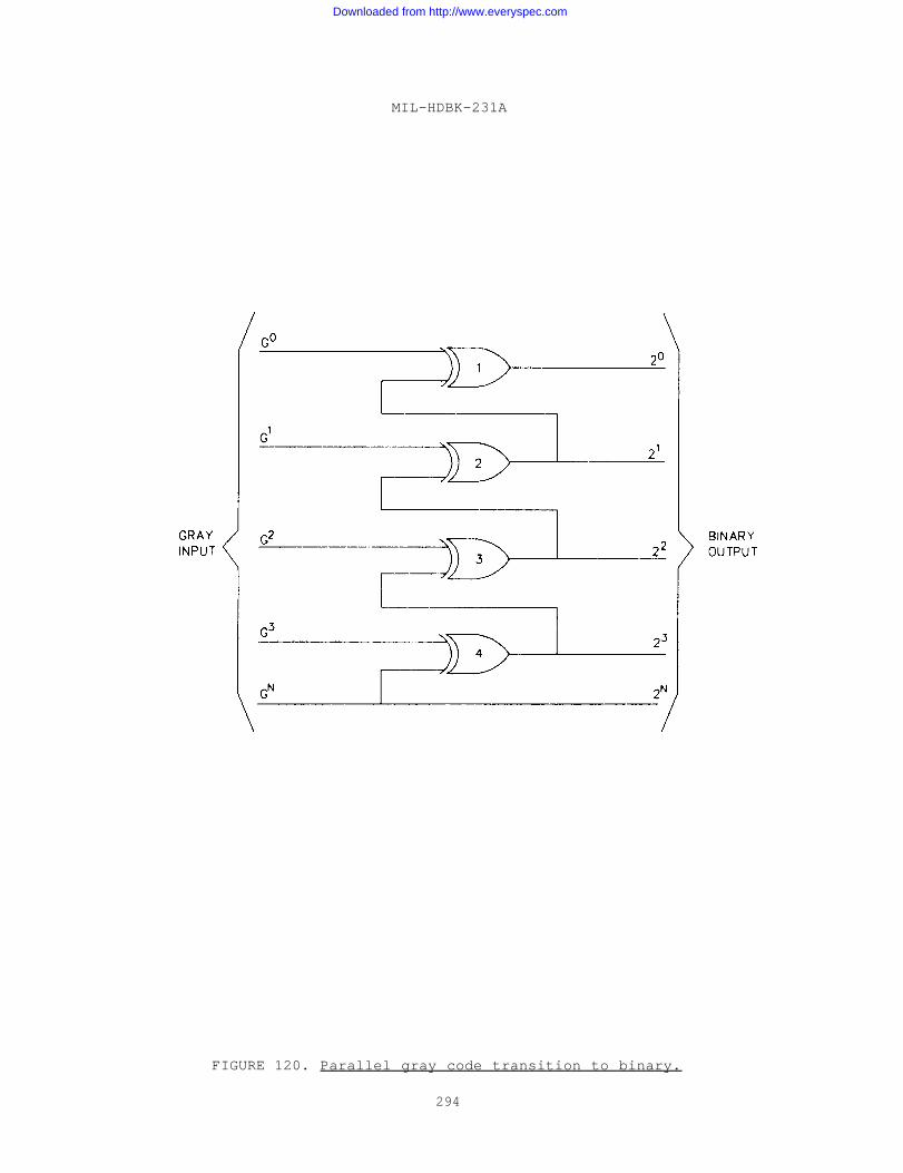
MIL-HDBK-231A
FIGURE 120. Parallel gray code transition to binary.
294
Downloaded from http://www.everyspec.com
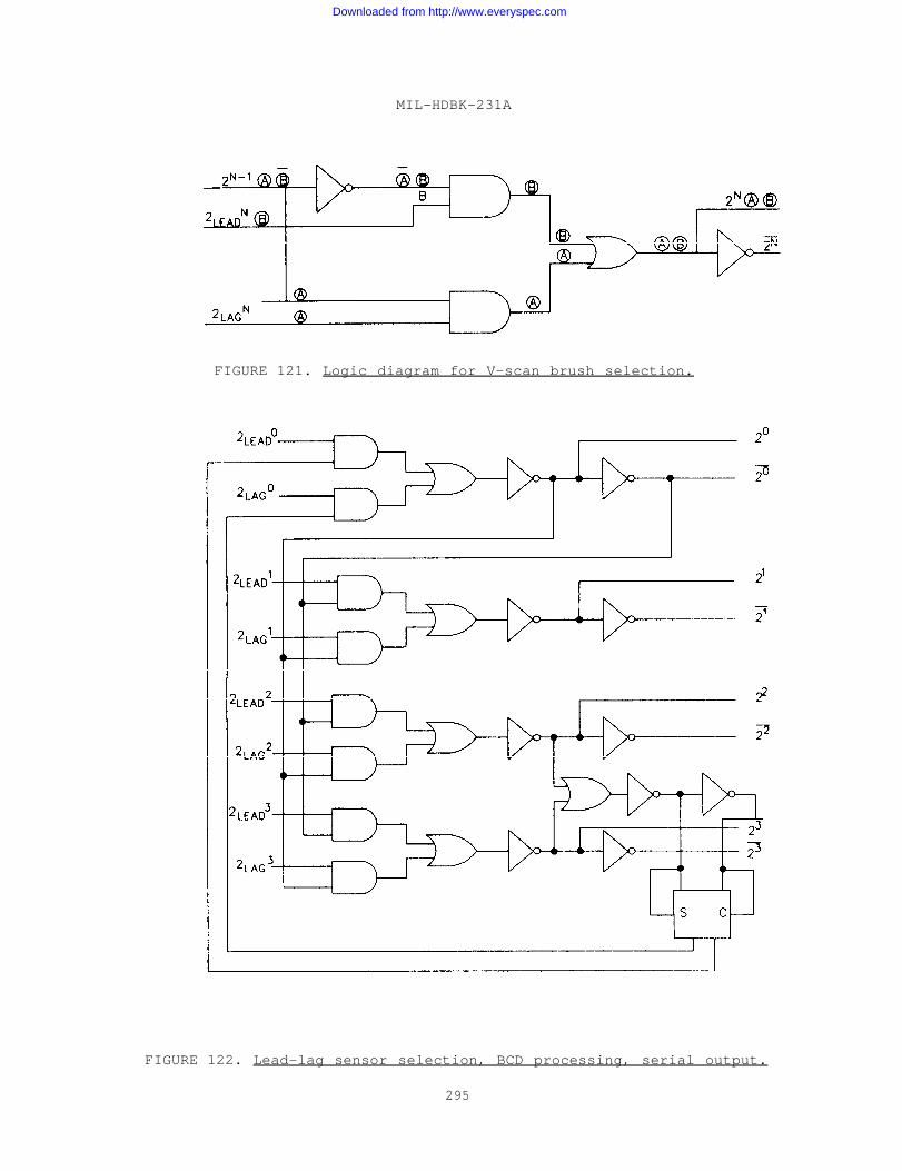
MIL-HDBK-231A
FIGURE 121. Logic diagram for V-scan brush selection.
FIGURE 122. Lead-lag sensor selection, BCD processing, serial output.
295
Downloaded from http://www.everyspec.com
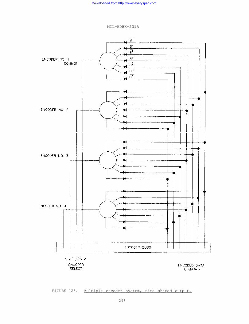
MIL-HDBK-231A
FIGURE 123. Multiple encoder system, time shared output.
296
Downloaded from http://www.everyspec.com
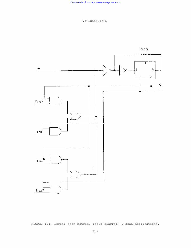
MIL-HDBK-231A
FIGURE 124. Serial scan matrix, logic diagram, V-scan applications.
297
Downloaded from http://www.everyspec.com
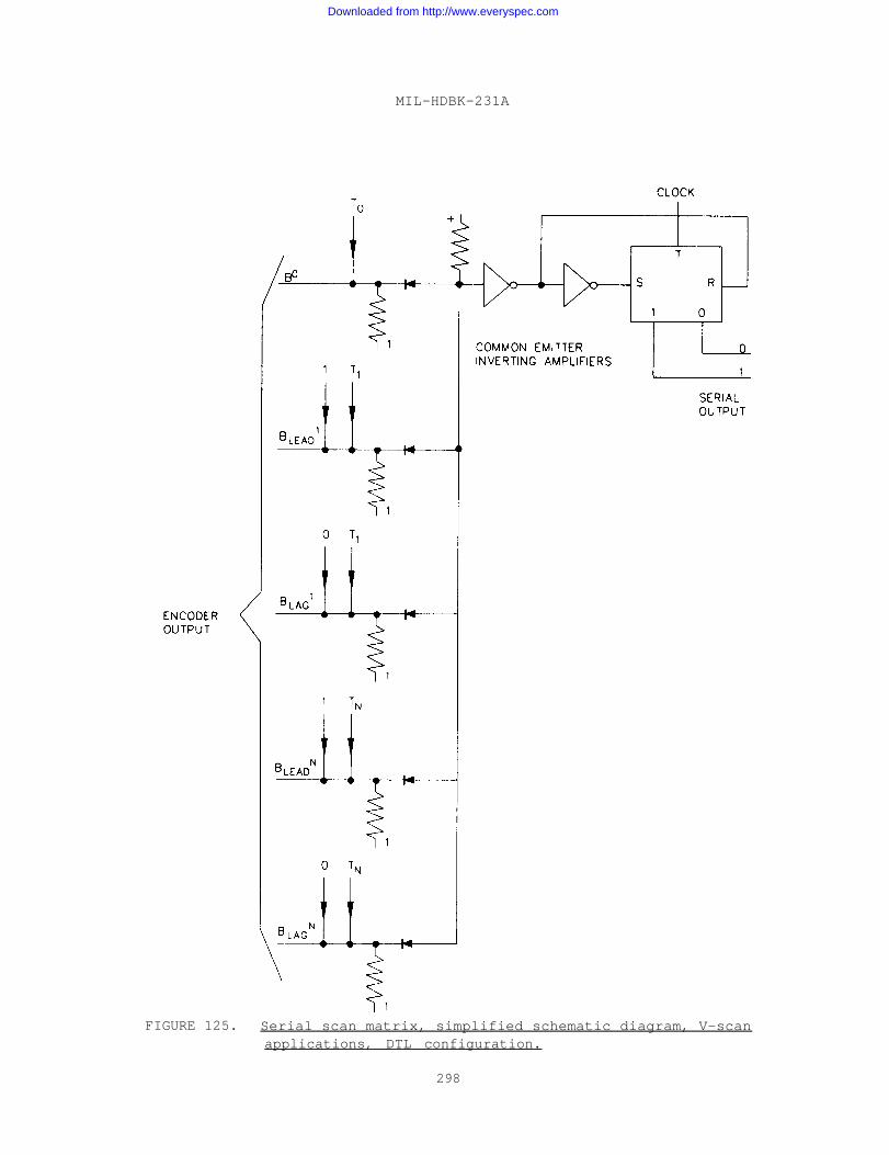
MIL-HDBK-231A
FIGURE 125. Serial scan matrix, simplified schematic diagram, V-scanapplications, DTL configuration.
298
Downloaded from http://www.everyspec.com
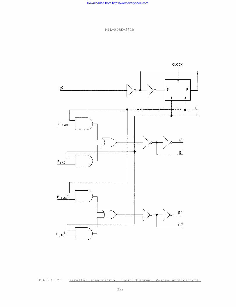
MIL-HDBK-231A
FIGURE 126. Parallel scan matrix, logic diagram, V-scan applications.
299
Downloaded from http://www.everyspec.com
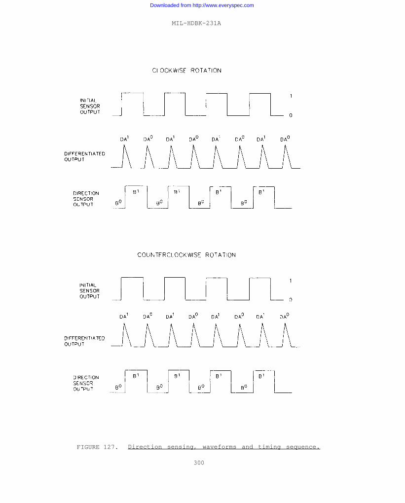
MIL-HDBK-231A
FIGURE 127. Direction sensing, waveforms and timing sequence.
300
Downloaded from http://www.everyspec.com
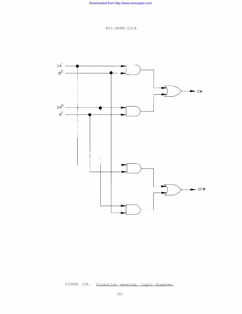
MIL-HDBK-231A
FIGURE 128. Direction sensing, logic diagram.
301
Downloaded from http://www.everyspec.com
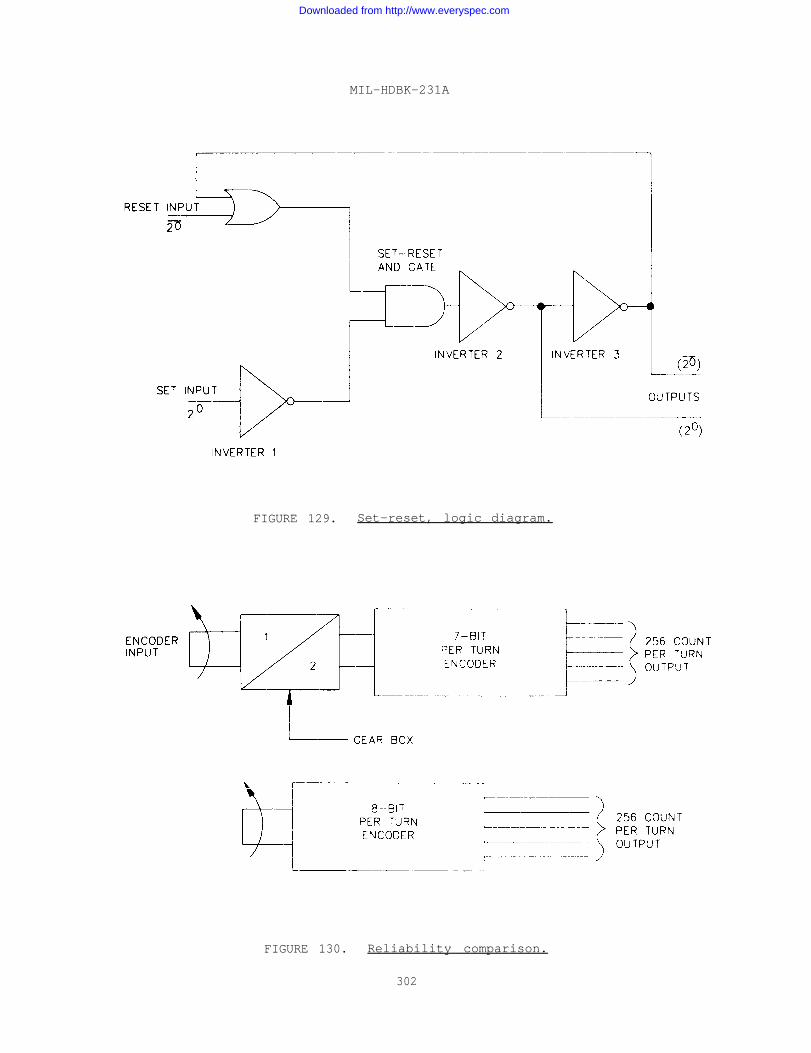
MIL-HDBK-231A
FIGURE 129. Set-reset, logic diagram.
FIGURE 130. Reliability comparison.
302
Downloaded from http://www.everyspec.com
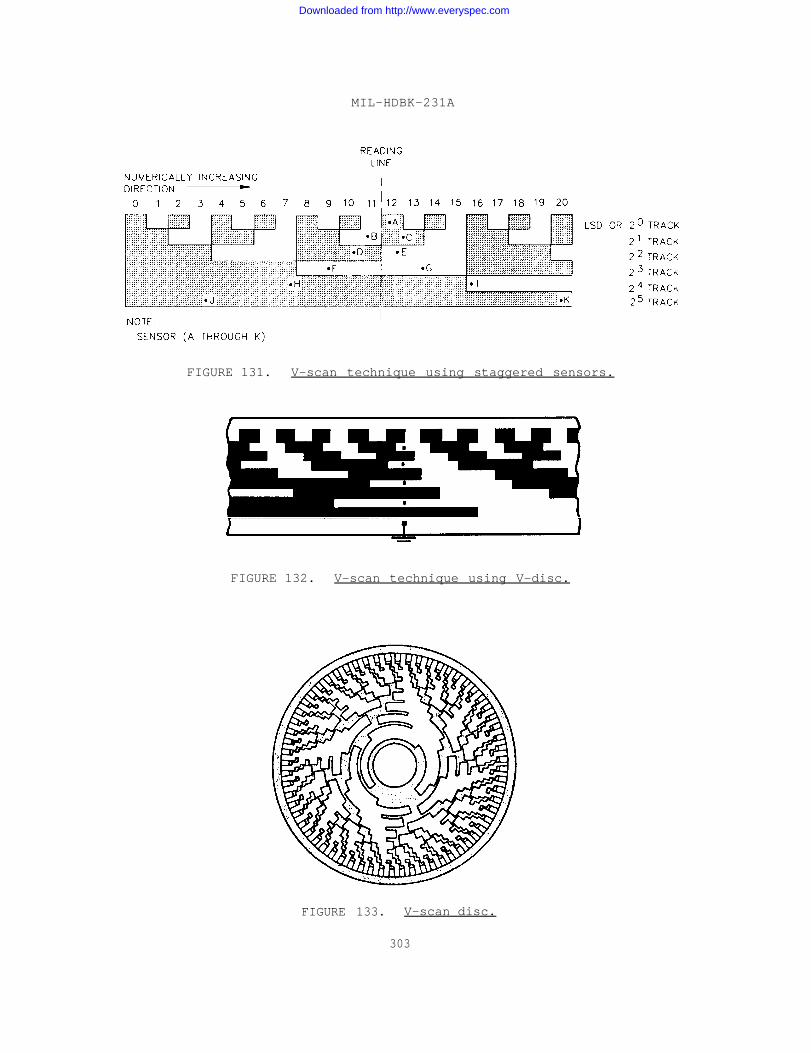
MIL-HDBK-231A
FIGURE 131. V-scan technique using staggered sensors.
FIGURE 132. V-scan technique using V-disc.
FIGURE 133. V-scan disc.
303
Downloaded from http://www.everyspec.com
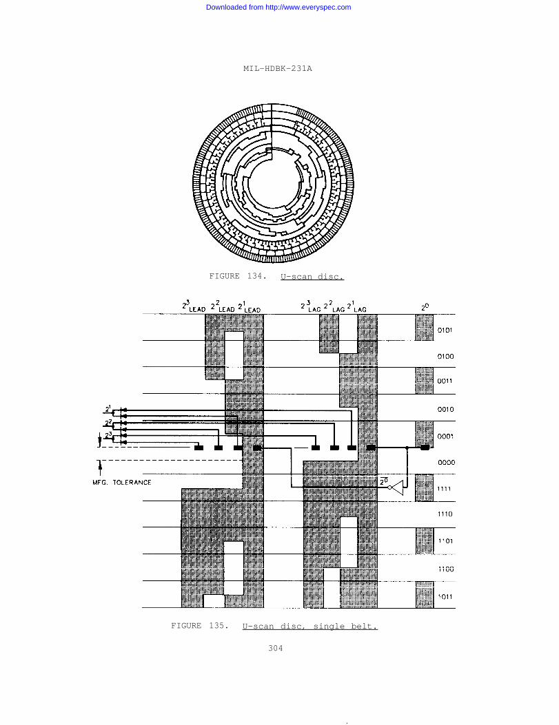
MIL-HDBK-231A
FIGURE 134. U-scan disc.
FIGURE 135. U-scan disc, single belt.
304
.
Downloaded from http://www.everyspec.com
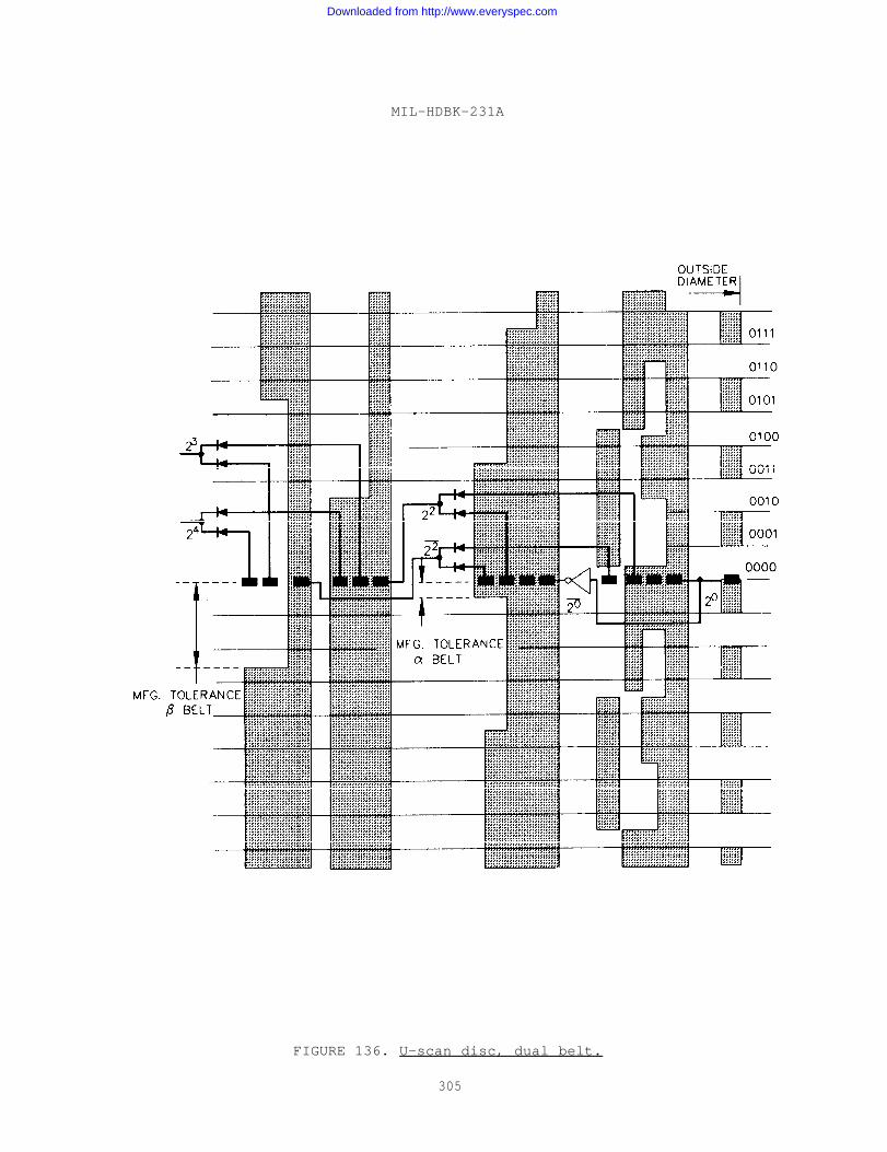
MIL-HDBK-231A
FIGURE 136. U-scan disc, dual belt.
305
Downloaded from http://www.everyspec.com
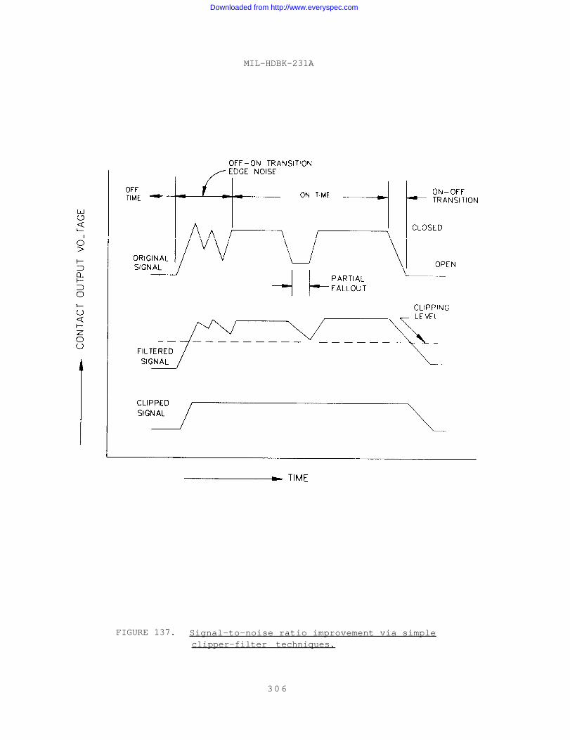
MIL-HDBK-231A
FIGURE 137. Signal-to-noise ratio improvement via simpleclipper-filter techniques.
306
Downloaded from http://www.everyspec.com
1
2
3
4
5
6
7
8
9
10
11
12
13
MIL-HDBK-231A
APPENDIX
SOURCE MATERIAL
Kliever, W. H., “Principles and Techniques for Direct-Reading DigitalTransducers,“ IRE Transactions on Industrial Electronics, April 1958,pp 357-465.
Danes, W. G., “Digital Transducers,” Aeronautical Systems Division,Dayton, Ohio, June 1962.
Cerni, R. H. and Foster, L. E., “Instrumentation for EngineeringMeasurements,“ John Wiley and Sons, Inc., New York, 1964, 66 pp.
Eisher, H. E., Dr., “Telemetry Transducer Handbook,” RadiationIncorporated, Melbourne, Florida, WADD TR 681-667, VOL II, Revision II,September 1963.
“Tiny Sensor-Transmitter Can Withstand Extreme Acceleration, GivesDigital Output,” NASA Tech. Brief (Brief 683-105681), November 1964,33 pp.
Roberts, T., “A Shaft-Position Digitizer Using Synchros,” Transactionsof the Society of Instrument Technology, March 1963, pp 377-485.
Hyde, T. T., “Developing Digital Transducers,” ISA Journal (60),June 1963, pp 585-600.
Staff of Borg-Warner Controls, “Vibrotron Pressure Transducer as aDepth Monitor in Oceanographic Applications,” Borg-Warner Corporation,Borg-Warner Controls, Santa Ana, California, January 1963, 66 pp.
Eastman, M. L. and Brown, P. E., “A Family of Digital Transducers,”Radio Corporation of America, Camden, New Jersey, pp 77-144.
Ludewig, F. A., “Digital Transducer Force Input-Binary Coded Output,”Control Engineering 88, June 1963.
Albus, J. S., “Digital Solar Aspect Sensor,” NASA, Goddard Space FlightCenter, Greenbelt, Maryland, pp 1-9.
Rider, N. E., and Bradley, E. F., “Digitization and Integration ofReflecting Galvanometers Deflections,” The Review of ScientificInstruments, 33 (1), January 1962, pp 25-26.
Blazek, H., and Zechnowitz, A., “Synchronous Rotating PendulumAccelerometer,“ Proceedings of the Rotating and Static PrecisionComponents Symposium, Department of the Navy, Naval Air Systems Command,Washington, D.C., April 1964, pp 36-49.
307
Downloaded from http://www.everyspec.com
MIL-HDBK-231A
APPENDIX
14
15
16
17
18
19
20
21
22
23
24
Womack, J. R., “Short-Period Digitizer - Project VT/072,” TheGeotechnical Corporation, Garland, Texas, Technical Report No. 64-65,October 1964.
“Electro-Optical Transducer Based on Moire Fringe,” Electronic DesignNews, 1965, pp 10–11.
Retta, R. A., “Analog To Digital Brushless, Shaft Encoder DevelopmentProgram,“ Proceedings of the Rotating and Static Precision ComponentsSymposium, Department of the Navy, Naval Air Systems Command, Washington,D. C., April 1964, pp 444-448.
Brewer, R. C., “Transducers for Positional Measuring Systems,”Proceedings of IEE, 110 (10), October 1963, pp 1818-1828.
“Feasibility Demonstration of Digital Displacement Sensing Techniques,”General Electric Company, Light Military Electronics Department,Schenectady, New York, ASD-TDR, 64-475, Technical Documentary Report,AF 33(657)-8284, May 1964, 56 pp.
Wullert, J. R., and Bossard, C. L., “Digital Transducer ResearchProgram, 5935-M,” Naval Air Development Center, Warminster,Pennsylvania, NADAC-ED-6029, Annual Report No. 1, December 1960, 33 pp.
Bossard, C. L., “Digital Transducer Research Program, 5935-M,”Naval Air Development Center, Warminster, Pennsylvania,NADAC-ED-L6291, December 1962, 17 pp.
Wullert, J. R., and Bossard, C. L., “Digital Transducer ResearchProgram, 5935-M,” Naval Air Development Center, Warminster,Pennsylvania, NADC-ED-6127, Annual Progress Report No. 2, August1962, 27 pp.
Ludewig, F. A., Johnson, D., and Gannon, W. T., “Applied ResearchStudy of Digital Displacement Sending Techniques,” ASD-TDR-62-904,Technical Documentary Report, General Electric Company, LightMilitary Electronics Department, Schenectady, New York, AF 33(657)-8284,February 1963, 54 pp.
“Applied Research Study of Digital Strain Sensing Techniques,” BendixCorporation, Research Laboratories Division, Southfield, Michigan,ASD-TDR-62-1046, Technical Documentary Report, AF 33(657)-8273,April 1963, 55 pp.
Pear, C. B., “Stability of Null Voltage of Hall Generators for DigitalTransducer Readout Heads,” Radiation Incorporated, Melbourne,Florida, Supplemental Report, AF 33(657)-7681, December 1963, 67 pp.
308
Downloaded from http://www.everyspec.com

MIL-HDBK-231A
APPENDIX
25
26
27
28
29
30
31
32
33
34
35
36
37
Pear, C. B., “Experimental Study of Application of Magnetic RecordingTo Digital Transducers,” Radiation Incorporated, Melbourne, Florida,ASD-TDR-63-381, Technical Documentary Report, AF 33(657)-7681,May 1963, 159 pp.
“Master Clock,” A. W. Haydon Company, Waterbury, Connecticut, 12 pp.
Kompass, E. J., “What About Digital Transducers,” Control Engineering,5 (7), July 1958, pp 94-99.
Guidice, D. A., and Harmon, W. L., “Ring-Laser Techniques for Angular-Rotation Sensing,” Air Force Science & Engineering Symposium,Aeronautical Systems Division, Air Force Systems, OAR 64-2,October 1963, 35 pp.
Macek, W., Salamon, R., Davis, D., and Cheatham, E., “ElectromagneticAngular Rotation Sensing,” Sperry-Rand Corporation, Sperry GyroscopeCompany, Great Neck, New York, AL TDR 64-210, Technical DocumentaryReport, AF 33(657)-11433, August 1964, 120 pp.
Brean, J. W., “A Prototype Model 13-Digit Sequential Size 11 OpticalEncoder,” Proceedings of the Rotating and Static Precision ComponentsSymposium, Department of the Navy, Naval Air Systems Command,Washington, D. C., April 1964, pp 223-241.
Klass, P. J., “Laser Flowmeter Measures Gases, Fluids,” AviationWeek and Space Technology, 82 (2), January 1965, pp 75-77.
“Laser Flowmeter Proposed by Sperry,” Electronic Design, 13 (2),January 1965.
Borucki, L., and Jahn, H., “The Digizet - A Simple Digital MeasuringInstrument of Versatile Use,” Siemens Review, 30 (3), March 1963,pp 107-110.
“Dynamic Deflection Measurements - Digital-Analog Output,” AlliedResearch Associates, Inc., Concord, Massachusetts, 2 pp.
Hamilton, S., “Improving Rate-Tables For Gyro Testing,” ElectronicsIndustry, 22 (9), September 1963, pp 72-75.
Hyde, J. L., “Developmental Studies of Nuclear Digital Transducers,”Instrument Society of America, 18th Annual ISA Conference and Exhibit,Chicago, Illinois, Preprint No. 43.2.63, September 1963, 12 pp.
Hyde, J. L., “Developing Digital Transducers,” ISA Journal, June1963, pp 55-60.
309
Downloaded from http://www.everyspec.com
MIL-HDBK-231A
APPENDIX
38
39
40
41
42
43
44
45
46
47
48
49
50
51
Dobriner, R., “Highly Stable Nuclear Transducer Has Digital Output,”Electronic Design, October 1963, pp 8-10.
Ratner, K. M., “Analog to Digital Converters, Shaft Position Encoders,”Electromechanical Design, Systems Designer’s Handbook, 9 (1),January 1965, pp 319-334.
Winder, C. F., “A Look At Coded Disks and Encoders,” ElectronicIndustries, 22 (6), June 1964, pp F2-F7.
“Pressure Instruments and Components, Capacitance PressureTransmitter/Indicator Systems,” Glassco Instrument Company, Pasadena,California, Technical Bulletin 107A, 2 pp.
“Digital Pressure Encoder Td-5,” Glassco Instrument Company, Pasadena,California, Technical Bulletin 103, 2 pp.
“Automatic Indicating Digital Standard Mercurial Sonar-Manometer,”Pulse and Digital Laboratories, Inc., Orange, New Jersey, Bulletin140-1, 4 pp.
“Digital Micrometer, Model 722,” Daytronic Corp., Dayton, Ohio,Bulletin T 722, 2 pp.
“PSC Digital Electromicrometer,” Physical Sciences Corp., Pasadena,California, Bulletin EM-2, 2 pp.
“Gage Pressure Pickups, Types P2825 and P2875,” Wiancko Engineering,Division of Tamar Electronics, Inc., Pasadena, California 2 pp.
Stansch, H. C., “A Linear Temperature Transducer With Digital Output,”Instrument Society of America, 19th Annual ISA Conference and Exhibit,New York, Preprint No. 11.2-2-64, October 1964, pp 1-8.
“Digital Liquid Level System,” Trans-Sonics Inc., Burlington,Massachusetts, Product Note 2871, 4 pp.
Werner, F. D., “Digital Pressure Gage Project For the Month EndingSeptember 16, 1954,” University of Minnesota, Institute of Technology,Minneapolis, Minnesota, Seventeenth Status Report, AF 18(600)-675,September 1954, 3 pp.
Heikkila, W. J., “A Radio Frequency Probe for Electron DensityMeasurements,“ Conference on Direct Aerometric Measurements in theLower Ionosphere, University of Illinois, Urbana, Illinois, GrantNSG-269-62, October 1963, 21 pp.
Hurst, S. L., “A Simple Capacitance Measuring Circuit With DigitalPresentation,“ Electronic Engineering, September 1964, pp 596-599.
310
Downloaded from http://www.everyspec.com
52
53
54
55
56
57
58
59
60
61
62
63
64
65
MIL-HDBK-231A
APPENDIX
Snyder, J. B., “Digital Counter Configuration,” Data SystemsEngineering, December 1963, pp 16-18.
Howell, F. S., “Trends in Telemetering Transducers,” Instrumentsand Control Systems 107, June 1962.
McNish, A. G., “Lasers for Length Measurement,” Science 146 (3641),October 1964, pp 177-182.
Robbins, L., “One-Brush Encoder,” Instruments and Control Systems,36 (2), February 1963, pp 103-105.
Sharp, E. M., Coss, B. A., and Jaffe, L., “A Digital AutomaticMultiple-Point Pressure-Recording System,” ISA Proceedings,1952, pp 236-241.
Katzive, R. H., “A-D Converters Use Instruments, Circuits,” DataSystems Design, December 1964, pp 25-28.
“Direct Digital Pressure Transducer,” Aviation Week and Space Technology,82 (2), January 1965.
“Plug-in Electronics Modules for Digital Pulse Output,” DynamicsResearch Corporation, Stoneham, Massachusetts, 2 pp.
Dickson, T., “Selecting Strain Transducers for Automatic Applications,”Automation, November 1962, pp 85-89.
“Sensor . . . What’s Happening in the News,” ISA Journal, 10 (8),August 1963.
Tone, P. A., Brown, W. R., and Walter, J. M., “Analog-To-DigitalConverter For High Accuracy, Severe Environment Operation,” AerospaceSystems, Dynatronics, Inc., Orlando, Florida, Final Rpt., NASA-5472,April 1964, 47 pp.
“Stan: New Approach to Aircraft Take-Off,” Electromechanical DesignComponents and Systems, 8 (111), November 1964, pp 40-43.
“Development of An Integrated Circuit, Ten-Bit Analog-To-DigitalConverter,“ Fairchild Camera and Instrument Corporation, FairchildSpace and Defense Systems, Palo Alto, California, PA-213, Final Rpt.,NOnr-4223(00), July 1964, 54 pp.
Gutorova, A. N., “New Design Method for Electrostatic DigitalVoltmeters,“ translated from Izmeritel’naya Tekhnika (7), July 1963,pp 32-34.
311
Downloaded from http://www.everyspec.com

MIL-HDBK-231A
APPENDIX
66
67
68
69
70
71
72
73
74
75
76
77
78
79
80
81
Sorokin, F. A., “New Digital Instruments,” translated from Izmeritel’nayaTekhnika (4), April 1961, pp 49-53.
“Monsanto Tries Direct Digital Control,” Chemical and Electronic News,June 1962, pp 32-33.
Nepveux, D. L. “Digital Circuits Achieve Automatic Control of RadarRange Tracking,” Chemical and Electronic News, December 1961, pp 46-50.
Himler, G. J., and Chafin, R. L., “Digital Measurements of Frequencyand Time,” Electro-Technology, May 1963, pp 93-97.
Von Bose, R. J., “Digitizing Flight-Test Data Readout,” ISA Journal,8 (4), April 1961, pp 52-55.
Palevsky, M., “Evaluating Digital Converters,” Instruments and ControlSystems, 38, January 1965.
Friauf, W. S., “Dynamic Characteristics of Analog-Digital Converters,”Instruments and Control Systems, 38, January 1965, pp 111-114.
Meister, J. B., “Stroboscopic Digital Readout,” Electro-Technology,May 1961, pp 162-163.
Evans, D. S., “The ‘Digitima’ - A Decimal Multi-Turn Time Digitizer,”Electronic Engineering, November 1963, pp 712-716.
Koppe, H., “Expansible UHF Cavity Extensometer,” Electrical DesignNews, 9 (15), December 1964, pp 8-10.
Hauer, J. R., “Shuttered Photoresistors Indicate Pressure,” ElectricalDesign News, 9 (15), December 1964, pp 37-39.
Kluge, J. E., “Pressure Diaphragm Modulates Coil Impedance,” ElectricalDesign News, 9 (15), December 1964, pp 40-41.
Novitskii, P. V., “Provision of Frequency Transducers for All Electricaland Nonelectrical Quantities,” translated from Izmeritel’naya Tekhnika(4), April 1961, pp 16-21.
Eriksson, G., and Tove, P. A., “A Simple Digital Time-IntervalMeasuring Circuit,” Electronic Engineering, September 1963, pp 598-599.
Goldwater, F. J., “Low-Cost Digital System Records Weather Data,”Electronics, 37 (2), January 1964, pp 34-36.
“Nuclear Ship Savannah to Get Digital Rod Control Systems,” ControlEngineering, 9 (10), October 1962, pp 22-24.
312
Downloaded from http://www.everyspec.com

MIL-HDBK-231A
APPENDIX
82
83
84
85
86
87
88
89
90
91
92
93
94
95
Karlson, E. L., “Pressure Data System Uses Digital Transducers,”Electronics, 34 (50), December 1964, pp 76-79.
Padlog, J., and Gallagher, R. H., “Measurement of Angular Displacementsof Practical Wind Structures by the Moire Fringe Technique,” BellAerospace Corporation, Bell Aerosystems Company, Buffalo, New York,FDL TDR 64-42, Tech. DOC. Rpt. AF 33 (657)-7486, September 1964, 50 pp.
“Digital Pressure Transmitter,” Review of Scientific Instruments,September 1952, 2 pp.
“RPM Model 506A,” Hewlett-Packard Company, Palo Alto, California,WADD TR 61-67, vol. II, Suppl. 1, November 1961, 1 pp.
Barker, R. H., “Transducer - Digital Data Transmission,” Institute ofElectrical Engineers Proceedings, January 1956, pp 42-44.
Weinreb, S., “Digital Radiometer,” IRE Proceedings, 49 (6), June 1961.
“Means of Gathering Information by the Digital-Cyclic TelemeteringSystem,“ The Brown Boveri Review, 50 (8), August 1963, pp 492-495.
Hochman, D., “Digital Data Compressors Control Space-GroundTransmissions,“ Space/Aeronautics, 37 (15), June 1963, pp 64-68.
“Digital Techniques in Airborne Data Acquisition,” Automatic Control,14, February 1961, pp 17-41.
“Digital Techniques in Airborne Data Acquisition - Part II,” AutomaticControl, 14 (7), March 1961, pp 41-49.
Mash, D. H., “An Electroluminescent Digital Indicator with a SiliconCarbide Coding Matrix,” Journal of Scientific Instruments, 37,February 1960, pp 47-50.
Dunlap, C., Rindner, W., Doering, G., Wonson, R., and Bernard, W.,“Research On Electro-Mechanical Integrated Transducers,” RaytheonCompany, Research Division, Waltham, Massachusetts, AL-TDR 64-132,Tech. Doc., Rpt. AF 33(657)-10847, June 1964, 101 pp.
Coss, B. A., Daykin, D. R., Jaffe, L., and Sharp, E. M., “A DigitalAutomatic Multiple Pressure Recorder,” National Advisory Committee forAeronautics, Technical Note 2880, 29 pp.
“Digital Transducer Study,” Servomechanisms, Inc., Research Division,Goleta, California, WADD Tech. Rpt., Final Rpt. AF 33(616)-6993,January 1961, 40 pp.
313
Downloaded from http://www.everyspec.com
MIL-HDBK-231A
APPENDIX
96
97
98
99
100
101
102
103
104
105
106
107
Sifferien, T. P., and Hocking, W. M., “A Digital Recording System ForSatellite Tracking Data,” NASA, Goddard Space Center, Greenbelt,Maryland, NASA TN D-672, Tech. Note, May 1961, 23 pp.
“Multiple Frequency Measurement of Material Properties,” IndustrialNucleonics Corporation, Columbus, Ohio, April 1964, 45 pp.
Williams, B. M., “Digital Seismograph System,” Texas Instruments Inc.,Science Service Division, Dallas, Texas, AFCRL-63-433, Final Rpt.AF 19(628)-472, March 1963, 100 pp.
Lake, H. L., “Broadband Digital Seismometer Evaluation,” TexasInstruments Inc., Dallas, Texas, AFCRL-64-33, Final Rpt. AF 19(628)-2986, February 1964, 67 pp.
Gilley, G. E., and Bunn, M. Lo, “A Prototype High Speed Digital SystemFor Hotshot Tunnels,” Arnold Engineering Development Center, AirResearch and Development Command, USAF, AEDC-TN-60-177, AF 40(600)-800S/A 11 (60-110), October 1960, 49 pp.
Kierner, F. A., “A Digital Command System For Satellites,” NASA, GoddardSpace Flight Center, Greenbelt, Maryland, NASA TN D-1076, Tech. Note,February 1962, 9 pp.
Githens, J. A., and Peters, T. R., “Digital Equipment For the AntennaPointing System,” The Bell System Technical Journal, July 1973,pp 1223-1252.
Albus, J. S., “A Digital Solar Aspect Sensor,” NASA, Goddard SpaceFlight Center, Greenbelt, Maryland, NASA TN D-1062, Tech. Note,September 1961, 9 pp.
Crozier, K., and McCarley, H., “A Leveling Scheme For an InertialPlatform Utilizing A Digital Accelerometer,” U. S. Army, MissileCommand, Inertial Systems Development Branch, Army Inertial Guidance andControl Laboratory, Redstone Arsenal, Alabama, RG-TG-63-27,September 1963, 13 pp.
Brentnall, B., and Horton, W. H., “A Method of Data Acquisition andSystem Control Through Time Sharing of Mixed Inputs,” StanfordUniversity, Stanford, California, AF AFOSR138 63, February 1963, 33 pp.
Johnson, H. L., and Mitchell, R. L., “A Completely Digitized Multi-Color Photometer,” Arizona University, Communications of the Lunar andPlanetary Laboratory, 1 (14), June 1962, pp 73-81.
Krolak, L. J., “Fiber Optics and Its Use in Electro-Optical Devices,”Light and Heat Sensing, Sixth Agard Avionics Panel Meeting, Paris,France, July 1962, pp 297-310.
314
Downloaded from http://www.everyspec.com
108
109
110
111
112
113
114
115
116
117
118
119
MIL-HDBK-231A
APPENDIX
Desai, U. D., Van Allen, R. L., and Porreca, G., “Explorer XIISatellite Instrumentation For the Study of the Energy Spectrum of CosmicRays,“ NASA, Goddard Space Flight Center, Greenbelt, Maryland, NASA
Tech. Note, TN-D 1698, May 1963, pp 1-16.
Githens, I. A., and Peters, T. R., "Digital Equipment For the AntennaPointing System,” Data Systems Engineering, September 1963, pp 6-15.
Lundy, R. A., “100-McDigitron - A Digital Time Analyzer,” The Review of
Scientific Instruments, 34(2), February 1963, pp 146-149.
Pelah, I., and Maydan, D., "High Accuracy Low Current DigitalIntegrator, “ IRE Transactions on Nuclear Science, 9, November 1962,pp 27-31.
Teitel, T., “A Binary to Decimal Conversion Circuit,” ElectronicEngineering, 35 (421), March 1963, pp 180-182.
Marshall, R. C., “A Direct Current Integrator With Digital Output,”Journal of the British IRE, 24 (4), October 1962, pp 287-292.
Couch, R. P., “Applications of Radioisotope Liquid Level Gages At TheAir Force Rocket Propulsion Laboratory,” Air Force Rocket PropulsionLab., Research and Technology Div., Air Force Systems Command,Edwards Air Force Base, California, RPL-TDR-64-123, July 1964, 29 pp.
“Research and Development of Techniques and Equipment for Solid StateDigital Computers,” Westinghouse Air Brake Company, Falls Church,Virginia, TR-WADD-60-339, Summary Tech. Dec. Rpt., AF 33(616)-6366,April 1960, 72 pp.
Lee, D. Y., “A Servo-Type Intermittent Digital Readout for PortableInstruments,” U. S. Naval Radiological Defense Laboratory, SanFrancisco, California, Research and Development Tech. Rpt.,USNRDL-TR-459, August 1960, 21 pp.
“STL Digital Integrating Accelerometer,” Space Technology Laboratories,Inc., One Space Park, Redondo Beach, California, 7 pp.
Goodstein, L. P., “Two Electronic Analog-To-Digital Converters,”Danish Atomic Energy Commission, Research Establishment Rise,Electronics Dept., Roskilde, Denmark, Riso Rpt. No. 80, February1964, 77 pp.
Sear, B. E., “Research For High Speed Analog-To-Digital ConversionTechniques,“ Electronic Systems and Products Div., Marting Company,Baltimore, Maryland, Tech. Dec. Rpt., AF 33(657)-11370, AL TDR-64-154~August 1964, 207 pp.
315
Downloaded from http://www.everyspec.com
MIL-HDBK-231A
APPENDIX
120
121
122
123
124
125
126
127
128
129
130
131
132
133
134
Cerni, R. H., “Transducers in Digital Process Control,” Instrumentsand Control Systems, 37 (9), September 1964, pp 123-126.
Everett, J. E., “Counting For High Speed Control,” Automation, June1960, pp 92-96.
Clifford, W., “DVM Data Systems,” Instruments and Control Systems,37 (12), December 1964, pp 105-107.
“Transducers in Measurement,” Electronics Engineering, July 1958,pp 60-61.
“Voltage and Current Generating Transducers,” Electronics Engineering,July 1958, pp 62-64.
“Variable Parameter Transducers,” Electronics Engineering, July 1958,pp 65-67.
“Transducer Application,” Electronics Engineering, July 1958, pp 68-70.
“An Optical Digital Transducer System,” Automatic Control, 6 (2),February 1957.
“Nu-Digit Pressure Transducers,” Charter Wire, Inc., CharterLaboratories, Northport, Long Island, New York, 2 pp.
“Nu-Digit Temperature Transducer Model 1202,” Charter Wire, Inc.,Charter Laboratories, Northport, Long Island, New York, PreliminaryBulletin, September 1964, 1 pp.
“Nu-Digit Gas Density Transducer Model 1801,” Charter Wire, Inc.,Charter Laboratories, Northport, Long Island, New York, preliminaryBulletin, September 1964, 2 pp.
“Nu-Digit Shaft Position Transducers Models 1901A and 1901B,” CharterWire, Inc., Charter Laboratories, Long Island, New York, preliminaryBulletin, November 1964, 2 pp.
Klein, M. L., Williams, F. K., and Morgan, H. C., "Digital Transducers,"Instruments and Automation, 30, July 1957, pp 1299-1300.
“Digital Pressure Transmitter,” Review of Scientific Instruments,September 1962, 2 pp.
Rose, I. A., “Photosensors and Spinning Disc Give Micro Measurements,”Electronic Design News, 10(3), March 1965, pp 50-51.
316
Downloaded from http://www.everyspec.com
MIL-HDBK-231A
APPENDIX
135 “Develops Miniature, Lightweight Laser Integrating Gyro,” Research/Development, 16(3), March 1965.
136 Kliever, W. H., “Principles and Techniques for Direct ReadingDigital Transducers,” DRE Transactions on Industrial Electronics, PGIE5, April 1958, pp 17-44.
137 “Three-Axis Coordinate Measuring Machine,” Sheffield Corporation,
Dayton, Ohio, 12 pp.
138 “Moire Fringe Vibration Sensor Model MFVS,” Microspace Inc.,Englewood, New Jersey, 2pp.
139 “Moire Fringe Transducer Model MFT,” Microspace Inc., Englewood,New Jersey, 2 pp.
140 “HOW to Use Shaft Encoders,” Datex Corporation, Monrovia, California,85 pp.
141 “The Microgon Encoder,” Muirhead Vactric Components Limited,Beckenham, Kent, UK, 4 pp.
317
Downloaded from http://www.everyspec.com

MIL-HDBK-231A
INDEX
Paragraph
Absolute detection. . . . . . . . . . . . . . . . . . . 5.3.2.3.2Absolute encoders . . . . . . . . . . . . . . . . . . . 5.4.6.1.3
5.10.1.2.2Absolute vs. incremental. . . . . . . . . . . . . . . . 5.4.4.1.2
5.10.1.2.2.4Acceptance testing. . . . . . . . . . . . . . . . . . . 5.7.5.4Accuracy. . . . . . . . . . . . . . . . . . . . . . . . 5.4.6.7.3Accuracy - bearings. . . . . . . . . . . . . . . . . . 5.5.2.3.1Accuracy - energy coupled encoder . . . . . . . . . . . 5.4.7.2.2Accuracy factors, encoder error, and minimization . . . 5.10.3Adaptability of design. . . . . . . . . . . . . . . . . 5.5.5.2Adapter assemblies. . . . . . . . . . . . . . . . . . . 5.5.4.5Addition of natural binary numbers. . . . . . . . . . . 5.9.1.10Advantages of a 2-bit encoder . . . . . . . . . . . . . 5.3.3.3.2Alignment check . . . . . . . . . . . . . . . . . . . . 5.7.5.7Altitude module . . . . . . . . . . . . . . . . . . . . 5.4.7.3.3Ambiguity. . . . . . . . . . . . . . . . . . . . . . . 5.3.2.3.3
5.10.3.3Ambiguity in scanning . . . . . . . . . . . . . . . . . 5.6.2.1Amplification. . . . . . . . . . . . . . . . . . . . . 5.3.4.1.1Applicability. . . . . . . . . . . . . . . . . . . . .1.2Applications . . . . . . . . . . . . . . . . . . . . .5.10.1Applications - general. . . . . . . . . . . . . . . . . 5.10.1.1Applications, tradeoffs, and error. . . . . . . . . . . 5.10Automatic test equipment. . . . . . . . . . . . . . . . 5.7.5.2.1Availability of precision bearings. . . . . . . . . . . 5.8.1.1
Background - capacitive encoders. . . . . . . . . . . . 5.4.5.1Background - contact encoders . . . . . . . . . . . . . 5.4.3.1Background - magnetic encoders. . . . . . . . . . . . . 5.4.4.1Background - mounting arrangements. . . . . . . . . . . 5.5.4.1Background - optical encoder. . . . . . . . . . . . . . 5.4.6.1Background - special encoders . . . . . . . . . . . . . 5.4.7.1Basic considerations - error factors. . . . . . . . . . 5.4.8.1Basic detection techniques. . . . . . . . . . . . . . . 5.3.2.1.4Basic elements. . . . . . . . . . . . . . . . . . . . . 5.8.2.1.2BCD . . . . . . . . . . . . . . . . . . . . . . . . . . 5.9.5.4.3BCD background . . . . . . . . . . . . . . . . . . . . . 5.9.3.2BCD encoders. . . . . . . . . . . . . . . . . . . . . . 5.9.12.4.2BCD implementation. . . . . . . . . . . . . . . . . . . 5.9.3.3BCD versus binary . . . . . . . . . . . . . . . . . . . 5.9.11.1Beamscan. . . . . . . . . . . . . . . . . . . . . . . . 5.8.2.2.2Bearings. . . . . . . . . . . . . . . . . . . . . . . .5.5.2.3
5.6.1.6.2Bearing quality . . . . . . . . . . . . . . . . . . . . 5.6.1.4.1Binary code 8-4-2-1 . . . . . . . . . . . . . . . . . . 5.9.1.8Binary coded decimals . . . . . . . . . . . . . . . . . 5.9.3.1
Page
1635
12627
12890394640
1365251
10318914116
13859201
1251251258792
312527513439411595
11310712410711996465856
102107
318
Downloaded from http://www.everyspec.com

MIL-HDBK-231A
INDEX
Paragraph
7-4-2-1 Binary coded decimals . . . . . . . . . . . . . 5.9.3.68-4-2-1 Binary coded decimals . . . . . . . . . . . . . 5.9.3.4Binary coded octal. . . . . . . . . . . . . . . . . . . 5.9.3.5Binary contacting encoders. . . . . . . . . . . . . . . 5.10.1.2.2.2Binary decimal system . . . . . . . . . . . . . . . . . 5.9.3Binary system. . . . . . . . . . . . . . . . . . . . . 5.9.1.5Biquinary coded decimals. . . . . . . . . . . . . . . . 5.9.3.8Brush current . . . . . . . . . . . . . . . . . . . . . 5.10.1.4.1
Capability summary. . . . . . . . . . . . . .Capacitive assemblies . . . . . . . . . . . .Capacitive encoders . . . . . . . . . . . . .Capacity. . . . . . . . . . . . . . . . . . .CCD - Development of. . . . . . . . . . . . .Cell output. . . . . . . . . . . . . . . . .Center-zero single turn encoders. . . . . . .Clamping disc assembly. . . . . . . . . . . .Clipping and filtering. . . . . . . . . . . .Code and scan. . . . . . . . . . . . . . . .Code selection criteria . . . . . . . . . . .Coded discs. . . . . . . . . . . . . . . . .Coding. . . . . . . . . . . . . . . . . . . .Coding techniques . . . . . . . . . . . . . .Combination and other scan techniques . . . .Combination codes . . . . . . . . . . . . . .Commutation. . . . . . . . . . . . . . . . .Comparative analysis of hardware. . . . . . .Comparative evaluation of size and structure.Comparisons and summaries - encoders. . . . .Component size. . . . . . . . . . . . . . . .Composition - saturable reactor heads . . . .Conclusion - functional systems . . . . . . .Conclusion - size and design. . . . . . . . .Construction of encoders. . . . . . . . . . .Contact encoder . . . . . . . . . . . . . . .
Contact noise. . . . . . . . . . . . . . . .Contact resistance. . . . . . . . . . . . . .Contacting versus non-contacting encoders . .Conversion circuits . . . . . . . . . . . . .Cost effectiveness - environmental testing. .Cost effectiveness - output circuits. . . . .Cost-optical encoders . . . . . . . . . . . .cost vs. performance. . . . . . . . . . . . .costs. . . . . . . . . . . . . . . . . . . .
. . . . . 5.10.2.10
. . . . . 5.4.5.2
. . . . . 5.4.5
. . . . . 5.11.2.2.6
. . . . . 5.8.2.1.1
. . . . . 5.4.8.2.2.2
. . . . . 5.9.10.4
. . . . . 5.5.4.4
. . . . . 5.10.3.5.2
. . . . . 5.11.2.2.4
. . . . . 5.9.11
. . . . . 5.5.2.4
. . . . . 5.9.5.4
. . . . . 5.9.2
. . . . . 5.10.3.3.8
. . . . . 5.9.7
. . . . . 5.10.1.4.5
. . . . . 5.6.1.6
. . . . . 5.5.6
. . . . . 5.4.8
. . . . . 5.6.1.4.2.1
. . . . . 5.4.4.3.1
. . . . . 5.3.6
. . . . . 5.5.6.2
. . . . . 5.5
. . . . . 5.2.15.4.35.8.1.25.10.2.10.1
. . . . . 5.7.5.6
. . . . . 5.10.2.7
. . . . . 5.4.8.2
. . . . . 5.6.3.8
. . . . . 5.7.5.3.1
. . . . . 5.6.4.1.2
. . . . . 5.4.6.7.4
. . . . . 5.5.5.1.1
. . . . . 5.6.5.2.4
Page
108108108127107101108129
1353131
1489443
11951
14314811947
1121051401141295853415628235444102593
13591
13442728978395288
319
Downloaded from http://www.everyspec.com

MIL-HDBK-231A
INDEX
Paragraph Page
Coupler. . . . . . . . . . . . . . . . . . . . . . . . 5.6.1.6.3Couplings . . . . . . . . . . . . . . . . . . . . . . . . . . . . 5.6.1.5.2Count characteristics and torque requirements . . . . . 5.11.1.6.1Count check. . . . . . . . . . . . . . . . . . . . . . 5.7.5.8Current limits . . . . . . . . . . . . . . . . . . . . 5.10.2.6Cyclic BCD. . . . . . . . . . . . . . . . . . . . . . . 5.905.4.4Cyclic binary decimal . . . . . . . . . . . . . . . . . 5.9.5.3Cyclic binary or Gray code. . . . . . . . . . . . . . . 5.9.4.2Cyclic code. . . . . . . . . . . . . . . . . . . . . . 5.6.2.4Cyclic codes. . . . . . . . . . . . . . . . . . . . . . 5.9.4.1Cyclic decimal - background . . . . . . . . . . . . . . 5.9.5.1Cyclic decimal - implementation . . . . . . . . . . . . 5.9.5.2Cyclic decimal code . . . . . . . . . . . . . . . . . . 5.9.5
Decimal system. . . . . . . . . . . . . . . . . . . . . 5.9.1.1Decimal system - example. . . . . . . . . . . . . . . . 5.9.1.1.1Definitions. . . . . . . . . . . . . . . . . . . . . . 3.Density. . . . . . . . . . . . . . . . . . . . . . . .5.5.3.2Description - capacitive encoders . . . . . . . . . . . 5.4.5.2.1Description - contact encoders. . . . . . . . . . . . . 5.4.3.2Description - magnetic encoders . . . . . . . . . . . . 5.4.4.2Description - optical encoder . . . . , . . . . . . . . 5.4.6.2Design considerations - encoders. . . . . . . . . . . . 5.5.1.1Design problems - capacitive encoder. . . . . . . . . . 5.4.5.4Design problems - contact encoders. . . . . . . . . . . 5.4.3.3Design problems - magnetic encoder. . . . . . . . . . . 5.4.4.5Design problems - optical encoders. . . . . . . . . . . 5.4.6.7Detailed requirements . . . . . . . . . . . . . . . . . 5.Detection. . . . . . . . . . . . . . . . . . . . . . .5.3.5.2
5.4.1.1Detection design characteristics. . . . . . . . . . . . 5.3.2.2Detection devices . . . . . . . . . . . . . . . . . . . 5.3.2.1Detection function. . . . . . . . . . . . . . . . . . . 5.3.2Detection mechanics . . . . . . . . . . . . . . . . . . 5.6.2Detection methods . . . . . . . . . . . . . . . . . . . 5.4.4.1.1Detection problems. . . . . . . . . . . . . . . . . . . 5.3.2.3Detector. . . . . . . . . . . . . . . . . . . . . . . . 5.4.5.2.1.1Direct decimal. . . . . . . . . . . . . . . . . . . . . 5.9.11.3Direction sensing logic . . . . . . . . . . . . . . . . 5.9.12.5Disc diameter and transition accuracy . . . . . . . . . 5.10.2.3.3Division of natural binary numbers. . . . . . . . . . . 5.9.1.13Driver circuit operation. . . . . . . . . . . . . . . . 5.6.3.16Driver circuits - comparative evaluation. . . . . . . . 5.6.3.18Driver circuits - description and analysis. . . . . . . 5.6.3.14Driver circuits - purpose and function. . . . . . . . . 5.6.3.13Dual channel preamplifier and logic processingCircuits. . . . . . . . . . . . . . . . . . . . . . . 5.4.5.2.1.4
5957
14791
13411311210960
109111111111
99100
3503225273544342530389
222315141359271532
11912513210576777575
33
320
Downloaded from http://www.everyspec.com

MIL-HDBK-231A
INDEX
Edge noise. . . . . . . . . . . . . . . .Electrical considerations . . . . . . . .Electrical design factors . . . . . . . .Electrical tests. . . . . . . . . . . . .Electrical testing - general. . . . . . .Electronic assembly . . . . . . . . . . .Encoder characteristics - general . . . .
Encoder classes . . . . . . . . . . . . .Encoder logic. . . . . . . . . . . . . .Encoder logic circuits - code translationEncoder of the future . . . . .Encoder noise . . . . . . . . .Encoder signal-to-noise ratio .Encoder size. . . . . . . . . .Encoder specifications. . . . .Encoder techniques. . . . . . .Encoder wear. . . . . . . . . .Encoder types . . . . . . . . .Encoders. . . . . . . . . . . .Energy coupled encoder. . . . .Environmental determinants. . .Environmental requirements. . .Environmental resistance. . . .Environmental tests - extremes.Environmental tests - typical .Environmental testing . . . . .Essential electronics . . . . .
.
.
.
.
.
.
.
.
.
.
.
.
.
.
.
.
.Example - energy coupled encoder.Example - serial scan processing.Excess-3 binary coded decimal . .Excess-3 code . . . . . . . . . .Excess-3 code - example . . . . .Excess-3 conversion . . . . . . .Excess-3 natural binary . . . . .External driver circuit-operatingExtreme low temperature . . . . .
Final assembly and alignment. . .First article testing . . . . . .Flexibility - output circuits . .Fresnel drag. . . . . . . . . . .Full word disc description. . . .Function. . . . . . . . . . . . .
.
.
.
.
.
.
.
.
.
.
.
.
.
.
.
.
.
.
.
.
.
.
.
.
.
.
.
.
.
.
.
.
.
.
.
.
.
.
.
.
.
.
.
.
.
.
.
.
.
.
.
.
.
.
.
.
.
.
.
.
.
.
.
.
.
.
.
.
.
.
.
.
.
.
.
.
.
.
.
.
.
.
.
.
.
.
.
.
.
.
.
.
.
.
.
.theory.. . . .
. . . .
. . . .
. . . .
. . . .
. . . .
. . . .
Functional systems - classification . . .Functional systems - description. . . . .Functional systems of encoder . . . . . .
.
.
.
.
.
.
.
.
.
.
.
.
.
.
.
.
.
.
.
.
.
.
.
.
.
.
.
.
.
.
.
.
.
.
.
.
.
.
.
.
.
.
.
.
.
.
.
.
.
.
.
.
.
.
.
.
.
.
.
.
.
.
.
.
.
.
.
.
.
.
.
.
.
.
.
.
.
.
.
.
.
.
.
.
.
.
.
.
.
.
.
.
.
.
.
.
.
.
.
.
.
.
.
.
.
.
.
.
.
.
.
.
.
.
.
.
.
.
.
.
.
.
.
.
.
.
.
.
.
.
.
.
.
.
.
.
.
.
.
.
.
.
.
.
.
.
.
.
.
.
.
.
.
.
.
.
.
.
.
.
.
.
.
.
.
.
.
.
.
.
.
.
.
.
.
.
.
.
.
.
.
.
.
.
.
.
.
.
.
.
.
.
.
.
.
.
.
.
.
.
.
.
.
.
.
.
.
.
.
.
.
.
.
.
.
.
.
.
.
.
.
.
.
.
.
.
.
.
.
.
.
.
.
.
.
.
.
.
.
.
.
.
.
.
.
.
.
.
.
.
.
.
.
.
.
.
.
.
.
.
.
.
.
.
.
.
.
...
.
.
.
.
.
.
.
.
.
.
.
.
.
.
.
.
.
.
.
.
.
.
.
.
.
.
.
.
.
.
.
.
.
.
.
.
.
.
.
.
.
.
.
.
.
Paragraph
5.7.5.55.10.3.4.15.10.2.45.7.45.7.4.15.7.2.25.11.15.10.1.25.9.125.9.12.35.8.35.6.4.3.25.10.3.4.25.11.1.5.15.10.1.45.4.15.10.2.3.65.45.4.25.4.7.25.5.55.5.5.15.5.5.1.25.7.5.3.35.7.5.3.25.7.5.35.10.1.2.2.15.4.7.2.15.9.12.4.15.9.6.25.9.6.15.9.6.1.15.6.3.8.15.9.6.1.25.6.3.155.11.1.4.2.4
5.7.2.35.6.5.2.35.6.4.1.15.8.3.3.15.5.2.4.15.11.2.2.75.25.15.3
Page
90141133848482
1441261191229779
14214612923
133232439515152898988
12740
12311411311472
11476
146
8288789848
148109
11
321
Downloaded from http://www.everyspec.com

MIL-HDBK-231A
INDEX
Paragraph
5.4.5.2.1.55.6.1.6.45.6.1.4.2.35.5.2.14.5.4.6.6.22.15.6.2.35.9.4.45.9.4.35.9.85.9.5.4.25.4.7.3.5
5.11.1.4.2.15.11.1.4.2.25.10.1.3.15.5.2.25.6.3.7.2
5.9.7.15.9.7.25.9.7.35.4.6.6.15.3.3.4.25.9.2.15.3.2.3.15.4.6.1.25.10.1.2.15.10.1.2.1.15.5.2.4.25.10.1.2.1.25.4.5.35.5.2.4.35.6.1.25.6.1.2.25.7.2.45.3.5.15.3.1.25.3.1.15.3.15.6.15.3.1.35.6.1.2.15.4.8.1.25.6.3.175.6.1.5
Page
Gating circuits andGear train. . . . .Gear train - use ofGeneral design. . .
secondary. . . . .. . . . .. . . . .
335957459
371
5911010911611241
.
.
.
.
.
.
.
.
.
.
.
.
.
.
.
.
.
.
.
.
.
.
.
.
...........
.
.
.
.
.
.
.
.
.
.
.
...........
.
.
.
.
.
.
.
.
.
.
.
.
.
.
.
.
.
.
.
.
.
.
.
.
.
.
.
.
.
.
.
.
.
.
.
.
.
.
.
.
.
.
.
.
.
.
.
.
.
.
.
.
.
.
.
.
.
.
.
.
.
.
.
.
.
.
.
.
.
.
.
.
.
.
.
.
.
.
.
.
.
.
.
.
.
...
.
.
.
.
.
.
.
.
.
.
.
.
.
.
.
.
.
.
.
.
.
.
.
.
.
.
.
.
.
.
.
.
.
.
.
.
.
.
...............
.
.
.
.
.
.
.
.
.
.
.
.
.
.
.
.
.
.
.
.
.
.
.
.
.
.
.
.
.
.
.
.
.
.
.
.
.
.
.
.
.
.
.
.
. . .
. . .
. . .
. . .
. . .
. . .
. . .
.
.
.
.
.
.
.
.
.
.
.
.
.
.
.
.
.
.
.
.
.
General requirements. . . . .Glow discharge lamps. . . . .Government documents. . . . .Gray code. . . . . . . . . .Gray code - design characteristics.
.
.
.
.
.
.
.
.
.
.
.
.
.
.
.
.
.
.
.
.
.
.
.
.
.
.
.
.
.
.
.
.
.
.
.
.
.
.
.
.
.
.
.
.
.
.
.
.
.
.
.
.
Gray code - implementation.Gray-coded XS-3 BCD . . . .Gray or cyclic binary . . .Ground speed module . . . .
High temperature.High vacuum . . .Higher resolutionHousings. . . . .Hybrid coding . .
1461461284672
. . . . .
. . . . .
. . . . .
. . . . .
. . . . .
ICAO code . . . . 1141151153619
1061535
12612649
126344955558322121111541355417657
. . . . .ICAO code - background. . .ICAO code - implementation.Incandescent lamps. . . . .
circuits.Increasing complexity of logic processingIncrementalIncrementalIncremental
IncrementalIncrementalIncremental
code. . . . . . . . . . .detection . . . . . . . .encoders. . . . . . . . .
encoders - advantages vs.rate sensing discs. . . .without zero reference. .
. .
. .
. .
. . . . .
. . . . .
. . . . .
disadvantages.................
.
.
.
.
.
.
.
.
.
.
.
.
.
.
.
.
.
.
.
.
.
.
.
.
.
.
.
.
.
.
.
.
.
.
.
.
.
.
.
.
.
.
.
.
.
.
.
.
.
.
.
.
.
...............
. .
. .
. .
. .
. .
Inductive assemblies. . . . . .Inductive sensing discs . . . .Inertia as design considerationInertia - most important design
. . .
. . .
. . .
In-process inspections. . . . ...........
.
.
.
.
.
.
.
.
.
.
.
.
.
.
.
.
.
.
.
.
.
.
.
.
.
.
.
.
.
.
.
.
.
. .
. .
. .
. .
. .
. .
. .
. .
. .
. .
. .
. . . . . . . . . . . .design characteristics.
InputInputInputInputInputInputInput
devices . . . . . .function. . . . . .mechanics . . . . .problems. . . . . .speed. . . . . . .
........
.
.
.
.
.
.
.
.
Instrument errors . . . .Integral driver circuit .Interface and integration
322
Downloaded from http://www.everyspec.com

MIL-HDBK-231A
INDEX
Item name . . . . . . . .
Latch circuits. . . . . .Latch-follow-store logic.Latch techniques. . . . .Latitude module . . . . .Lead-lag sensor selectionLead-lag techniques . . .Length of service life. .Life.. . . . . . . . . .Line scan . . . . . . . .Light bank display. . . .Light detection . . . . .Light sources . . . . . .Limitations . . . . . . .Line capacitance. . . . .Line rise times . . . . .Logical “0” state . . . .Logical "1" state . . . .
Logic circuit problems. .Logic circuits - functionLogic circuits - purpose.
.
.
.
.
.
.
.
.
.
.
.
.
.
.
.
.
.
.
.
.
.
.
.
.
.
.
.
.
.
.
.
.
.
.
.
.
.
.
.
.
.
.Logic design characteristics.Logic devices . . . . . . . .
.
.
.
.
.
.
.
.
.
.
.
.
...........
Logic diagrams and truth tablesLogic functions . . . . . . . .Logic mechanics . . . . . . . .Logic processing. . . . . . . .Logic processing function . . .Logic processing. . . . . . . .Logic systems . . . . . . . . .Longitude module. . . . . . . .Low input shaft speed . . . . .Lower resolution. . . . . . . .Lubricant failure . . . . . . .Lubrication - bearings. . . . .
M-scan. . . . . . . . . . . . .
Magnetic encoders . . . . . . .
Magnetic reluctance . . . . . .Magnetic scan encoders. . . . .Major design factors. . . . . .Marker generator test . . . . .Maximum life versus reliabilityMaximum quanta rate . . . . . .
.
.
.
.
.
.
.
.
.
.
.
.
.
.
.
.
.
.
.
.
.
.
.
.
.
.
.
.
.
.
.
.
.
.
.
.
.
.
.
.
.
.
.
.
.
.
.
.
.
.
.
.
.
.
.
.
.
.
.
.
.
.
.
.
.
.
.
.
.
.
.
.
.
.
.
.
.
.
.
.
.
.
.
.
.
.
.
.
.
.
.
.
.
.
.
.
.
.
.
.
.
.
.
.
.
.
.
.
.
.
.
.
.
.
.
.
.
.
.
.
.
.
.
.
.
....
.
.
.
.
.
.
.
.
.
.
.
.
.
.
.
.
.
.
.
.
.
.
.
.
.
.
.
.
.
.
.
.
.
.
.
.
.
.
.
.
.
.
.
.
.
.
.
.
.
.
.
.
.
.
.
.
.
.
.
.
.
.
.
.
.
.
.
.
.
.
.
.
.
.
.
.
.
.
.
.
.
.
.
.
.
.
.
.
.
.
.
.
.
.
.
.
.
.
.
.
.
.
.
.
.
.
.
.
.
.
.
.
.
.
.
.
.
.
.
.
.
.
.
.
.
.
...
.
.
.
.
.
.
.
.
.
.
.
.
.
.
.
.
.
.
.
.
.
.
.
.
.
.
.
.
.
.
.
.
.
.
.
.
.
.
.
....
.
.
.
.
.
.
.
.
.
.
.
.
.
.
.
.
.
.
.
.
.
.
.
.
.
.
.
.
.
.
.
.
.
.
.
.
.
.
.
.
.
.
.
.
.
.
.
.
.
.
.
.
.
.
.
.
.
.
.
.
.
.
.
.
.
.
.
.
.
.
.
.
.
.
.
.
.
.
.
.
.
.
.
.
.
.
.
.
.
.
.
.
.
.
.
.
.
.
.
.
.
.
.
.
.
.
.
.
.
.
.
.
.
.
.
.
.
.
.
.
.
.
.
.
.
.
.
.
.
.
.
.
.
.
.
.
.
.
.
.
.
.
.
.
.
.
.
.
.
.
.
.
.
.
.
.
.
.
.
.
.
.
.
.
.
.
.
.
.
.
.
.
.
.
.
.
.
.
.
.
.
.
.
.
.
.
.
.
.
.
.
.
.
.
.
.
.
.
.
.
.
.
.
.
.
.
.
.
.
.
.
.
.
.
.
Paragraph
5.11.2.2.1
5.6.3.35.6.3.6.15.10.3.5.15.4.7.3.15.9.12.45.10.3.3.35.3.1.3.15.10.2.2.15.6.2.65.7.4.1.15.4.6.45.4.6.65.3.3.3.15.10.1.4.35.10.1.4.45.4.4.3.35.4.4.3.25.3.3.45.6.3.25.6.3.15.3.3.25.3.3.15.9.12.25.9.12.15.6.35.3.5.35.3.35.3.3.35.6.3.125.4.7.3.25.4.3.3.35.10.1.3.25.10.2.3.75.5.2.3.4
5.6.2.85.10.3.3.65.4.45.10.2.10.25.8.3.15.8.1.45.6.1.4.25.7.4.1.55.10.2.25.10.2.3.5
Page
148
6870
14240
12313913
1306084363618
12912929291967671717
12112067221718754126
12813347
6214027
13597935686
130132
323
Downloaded from http://www.everyspec.com

MIL-HDBK-231A
INDEX
Mechanical and electrical tests . . . . . . . . . . . .Mechanical inspection . . . . . . . . . . . . . . . . .Mechanized disc. . . . . . . . . . . . . . . . . . . .Microgon encoders. . . . . . . . . . . . . . . . . . .Military name plate data. . . . . . . . . . . . . . . .Minor problems. . . . . . . . . . . . . . . . . . . . .Modification. . . . . . . . . . . . . . . . . . . . . .Moire fringes. . . . . . . . . . . . . . . . . . . . .Monostrophic codes. . . . . . . . . . . . . . . . . . .
Monostrophic codes - direct coupling. . . . . . . . . .Monostrophic codes - storing. . . . . . . . . . . . . .Monostrophic codes used with long cables. . . . . . . .Monostrophic versus weighted codes. . . . . . . . . . .Most significant digit and least significant digit. . .Mounting clamp assembly . . . . . . . . . . . . . . . .Mounting requirements . . . . . . . . . . . . . . . . .Mountings and physical interfaces . . . . . . . . . . .Multiple encoders. . . . . . . . . . . . . . . . . . .Multiplication of natural binary numbers. . . . . . . .Multi-turn units and gearing . . . . . . . . . . . . .
Natural binary. . . . . .Natural binary numbers. .Natural binary system . .Need for computer controlGeomagnetic-tuned circuitNines‘ complement . . . .Noise error . . . . . . .Non-ambiguous coding. . .Non-contacting encoder. .
. . . . . . . . . . . . . . .
. . . . . . . . . . . . . . .
. . . . . . . . . . . . . . .
. . . . . . . . . . . . . . .encoders. . . . . . . . . . .. . . . . . . . . . . . . . .. . . . . . . . . . . . . . .. . . . . . . . . . . . . . .. . . . . . . . . . . . . . .
Noncyclic codes - nonreflected codes. . . . . . . . . .Non-government publications . . . . . . . . . . . . . .Nonreflected cyclic codes . . . . . . . . . . . . . . .Nonweighted binary codes. . . . . . . . . . . . . . . .Nuclear radiation. . . . . . . . . . . . . . . . . . .Number of revolutions . . . . . . . . . . . . . . . . .Number systems. . . . . . . . . . . . . . . . . . . . .Number systems and codes. . . . . . . . . . . . . . . .
Operation. . . . . . . . . . . . . . . . . . . . . . .Optical assemblies. . . . . . . . . . . . . . . . . . .Optical encoder. . . . . . . . . . . . . . . . . . . .
Optical rulings. . . . . . . . . . . . . . . . . . . .
324
Paragraph
5.7.1.15.7.35.3.2.1.35.8.2.15.11.2.25.8.1.55.11.2.2.95.8.2.1.3.25.6.3.55.10.3.3.15.6.3.5.25.6.3.5.35.6.3.5.15.9.11.25.9.1.1.25.5.4.35.6.1.5.15.5.45.9.12.4.35.9.1.125.5.2.5
5.9.5.4.15.9.1.65.9.1.94.15.4.4.65.9.1.45.10.3.45.6.2.25.2.25.8.1.35.10.1.2.2.35.9.62.25.9.5.55.9.45.11.1.4.2.35.3.1.2.15.9.15.9
5.4.4.3.55.4.6.55.4.65.10.2.10.35.8.3.2
Page
81831494
14894
1489569
138696969
119100515751
12410449
112101103
931
101141591093
127113
2113108146129999
303634
13597
Downloaded from http://www.everyspec.com

MIL-HDBK-231A
INDEX
Optical systems . . . . . . . . . . . .Order of precedence . . . . . . . . . .Other configurations - output . . . . .Other research. . . . . . . . . . . . .Output. . . . . . . . . . . . . . . . .
Output amplifiers . . . . . . . . . . .Output circuits - purpose and function.Output - description and analysis . . .Output design characteristicsOutput devices. . . . . .Output function . . . . .Output mechanics. . . . .Output - pulse shaping. .Overall accuracy. . . . .
Parallel scan processing.Parity bits . . . . . . .Patterns. . . . . . . . .Performance parameters ofPerformance parameters ofPerformance problem areas
. .
. .
. .
. .
. .
. .
. .
. .
. . . . .
. . . . .
. . . . .
. . . . .
. . .. .
. . . . .
. . . . .
. . . . .
. . . . .
.
.
.
.
.
.
.
.
.
.
.
.
.
.
.
.
.
.
.
.
.
.
.
.
.
.
.
.
.
.
.
.
.
.
.
.
.
.
.
.
.
.
.
.
.
.
.
.
.
.
.
.
.
.
.
.
.
.
.
.
.
.
.
.
.
.
.
.
.
.
.
.
.
.
.
.
.
.
.
.
.
.
.
.
.design and constructionsize. . . . . .. . . . . . . .
Performance vs. cost - scans. . . . . . .Phasescan. . . . . . . . . . . . . . . .Phasescan and Beamscan. . . . . . . . . .Pin contact encoders. . . . . . . . . . .PN silicon photovoltaic cell. . . . . . .Plus-minus spans with multispeed encodersPolarity. . . . . . . . . . . . . . . . .Polystrophic codes. . . . . . . . . . . .Precision bearing required. . . . . . . .Preliminary assembly and inspection . . .
.
.
.
.
.
.
.
.
.
.
.
.Preventing ambiguity in multi-turn encodersPrinciples of operation . . . . . .Printout. . . . . . . . . . . . . .Problems and solutions. . . . . . .Problems in contacting encoders . .Problems in non-contacting encodersPurpose. . . . . . . . . . . . . .
Quality assurance methods . . . . .Quality - bearings. . . . . . . . .Quantization error. . . . . . . . .
Radial and endReading system
play.. . . . . . .complications. . . .
. . .
. . .
. . .
. . .
. . .
. . .
. . .
. . .
. . .
. . .
. . .
.
.
.
.
.
.
.
.
.
.
.
.
.
.
.
.
.
.
.
.
.
.
.
.
.
.
.
.
.
.
.
.
.
.
.
.
.
.
.
.
.
.
.
.
.
.
.
.
.
.
.
.
.
.
.
.
.
.
.
.
.
.
.
.
.
.
.
.
.
.
.
.
.
.
.
.
.
.
.
.
.
.
.
.
.
.
.
.
.
.
.
.
.
.
.
.
.
.
.
.
.
.
.
.
.
.
.
.
.
.
.
.
.
.
.
.
.
.
.
.
.
.
.
.
.
.
.
.
.
.
.
.
.
.
.
.
.
.
.
.
.
.
.
.
.
.
.
.
.
.
.
.
.
.
.
.
.
.
.
.
.
.
.
.
.
.
.
.
.
.
.
.
.
.
.
.
.
.
.
.
.
.
.
.
.
.
.
.
.
.
.
.
.
.
.
.
.
.
.
.
.
.
.
.
.
.
.
.
.
Paragraph
5.4.6.32.35.6.4.5.25.8.2.35.3.5.45.4.1.25.6.4.45.6.4.15.6.4.25.3.4.25.3.4.15.3.45.6.45.6.4.35.3.1.2.3
5.9.12.4.45.9.1.75.8.2.1.3.15.6.1.45.5.1.35.8.15.6.2.13.25.8.2.2.15.8.2.25.4.3.45.4.6.6.45.9.10.35.10.2.85.6.3.65.4.6.7.25.7.2.15.6.2.125.8.2.1.35.7.4.1.25.6.4.3.15.4.8.2.15.4.8.2.21.3
5.7.25.5.2.3.35.4.8.1.15.10.3.1
5.5.2.3.25.4.8.2.2.3
Page
352
80962323797778222020777812
124102955545926796962638
1181347039826595847942431
824741
136
4643
325
I
Downloaded from http://www.everyspec.com

MIL-HDBK-231A
INDEX
Readout. . . . . . . . . . . . . . . . . . . . . . . .Recording oscillograph. . . . . . . . . . . . . . . . .Referenced documents. . . . . . . . . . . . . . . . . .Reliability at high speed . . . . . . . . . . . . . . .Reliability checking. . . . . . . . . . . . . . . . . .Reliability factors . . . . . . . . . . . . . . . . . .Reliability measurement . . . . . . . . . . . . . . . .Reliability testing . . . . . . . . . . . . . . . . . .Research - current programs . . . . . . . . . . . . . .Research and development. . . . . . . . . . . . . . . .Resolution. . . . . . . . . . . . . . . . . . . . . . .
Resonant frequency method . . . . . . . . . . . . . . .Ring lasers. . . . . . . . . . . . . . . . . . . . . .Rotating components . . . . . . . . . . . . . . . . . .
Sample configuration - output . . . . . . . . . . . . .Sampling circuits. . . . . . . . . . . . . . . . . . .Sampling circuits - design problem. . . . . . . . . . .Sampling techniques . . . . . . . . . . . . . . . . . .Saturable reactor and variable reluctance methods . . .Scanning. . . . . . . . . . . . . . . . . . . . . . . .Scan - comparison. . . . . . . . . . . . . . . . . . .Scans - summary. . . . . . . . . . . . . . . . . . . .Scope. . . . . . . . . . . . . . . . . . . . . . . . .Segment and sensor size . . . . . . . . . . . . . . . .Segment placement and eccentricity. . . . . . . . . . .Selecting antiambiguity logic . . . . . . . . . . . . .Selecting electrical requirements . . . . . . . . . . .Selecting general characteristics . . . . . . . . . . .Selecting output code . . . . . . . . . . . . . . . . .Selecting output notation . . . . . . . . . . . . . . .Selecting physical limitations. . . . . . . . . . . . .Selection of an encoder . . . . . . . . . . . . . . . .Selection of encoders for military use. . . . . . . . .Selector circuits. . . . . . . . . . . . . . . . . . .Self-checking encoders. . . . . . . . . . . . . . . . .Self-selecting scans. . . . . . . . . . . . . . . . . .Self-selecting U-scan . . . . . . . . . . . . . . . . .Self-selecting V-scan . . . . . . . . . . . . . . . . .
Sensor output. . . . . . . . . . . . . . . . . . . . .Separate switch assemblies. . . . . . . . . . . . . . .Sequence of operation . . . . . . . . . . . . . . . . .
Paragraph
5.11.2.2.55.7.4.1.32.5.10.2.3.45.10.3.55.10.2.35.10.2.2.35.7.5.25.8.25.85.8.2.1.3.35.10.1.35.10.2.3.25.11.2.2.85.4.4.45.8.3.35.6.1.6.1
5.6.4.5.15.10.2.95.6.3.45.10.305.35.4.4.35.6.2.55.6.2.13.15.6.2.131.15.4.3.3.25.4.3.3.15.11.1.35.11.1.55.11.1.65.11.1.25.11.1.15.11.1.45.115.11.25.6.3.95.6.5.2.25.6.2.105.6.2.10.25.6.2.10.15.10.3.3.55.10.1.4.25.3.2.1.25.4.5.2.1.65.6.3.6.1.1
Page
148841
13214213113187949295
128132148309858
8013468
143286066661
2525
1451461471441441451441477387636463
139129143371
326
Downloaded from http://www.everyspec.com

MIL-HDBK-231A
INDEX
Paragraph
Servo-encoder modules . . . . . . . . . . . . . . . . . 5.4.7.3Set-reset logic . . . . . . . . . . . . . . . . . . . . 5.9.12.6Set-reset selector circuit. . . . . . . . . . . . . . . 5.6.3.10Set-reset technique . . . . . . . . . . . . . . . . . . 5.10.3.5.4Shaft characteristics . . . . . . . . . . . . . . . . . 5.6.1.4.2.2Shaping. . . . . . . . . . . . . . . . . . . . . . . . 5.3.4.1.3Signals. . . . . . . . . . . . . . . . . . . . . . . . 5.4.5.2.1.3Signal-to-noise ratio . . . . . . . . . . . . . . . . . 5.4.6.7.1Single contact encoders . . . . . . . . . . . . . . . . 5.9.2.2Size. . . . . . . . . . . . . . . . . . . . . . . . . . 5.10.1.3.3
5.11.2.2.2Size and accuracy . . . . . . . . . . . . . . . . . . . 5.5.3.1Size, shape and performance . . . . . . . . . . . . . . 5.5.1SlOW rotational speed . . . . . . . . . . . . . . . . . 5.3.1.3.2Small slit alignment tolerances . . . . . . . . . . . . 5.4.8.2.2.1Solid state light sources . . . . . . . . . . . . . . . 5.4.6.6.3Special devices. . . . . . . . . . . . . . . . . . . . 5.4.7Special operating environment . . . . . . . . . . . . . 5.11.1.4.2Special purpose codes . . . . . . . . . . . . . . . . . 5.9.10Special purpose codes - background. . . . . . . . . . . 5.9.10.1Special purpose codes - implementation time and angle . 5.9.10.2Special purpose encoders. . . . . . . . . . . . . . . . 5.7.1.2Special scans. . . . . . . . . . . . . . . . . . . . . 5.6.2.11Specification checklist . . . . . . . . . . . . . . . . 5.10.1.4.6Specifications. . . . . . . . . . . . . . . . . . . . . 5.11.2.1Specifications, standards and handbooks . . . . . . . . 2.1.1Speed as design consideration . . . . . . . . . . . . . 5.6.1.3Standard hardware . . . . . . . . . . . . . . . . . . . 5.5.4-2Standard shapes and sizes . . . . . . . . . . . . . . . 5.5.1-2Stators. . . . . . . . . . . . . . . . . . . . . . . . 5.4.5.2.1.2Storage. . . . . . . . . . . . . . . . . . . . . . . . 5.3.4.1.2Storage, timing and conversion. . . . . . . . . . . . . 5.6.4.5Structural design and housing . . . . . . . . . . . . . 5.5.2Subtraction of natural binary numbers . . . . . . . . . 5.9.1.11Summary - contacting and non-contacting encoders. . . . 5.4.8.3Summary of design . . . . . . . . . . . . . . . . . . . 5.5.6.1Summary of interrelation of functions . . . . . . . . . 5.3.5Survey of encoders - general. . . . . . . . . . . . . . 4.2Switching condition utilizing two cam switches. . . . . 5.3.3.4.1Systems technology. . . . . . . . . . . . . . . . . . . 5.6
Tachometer encoder. . . . . . . . . . . . . . . . . . . 5.4.6.1.1Temperature extremes. . . . . . . . . . . . . . . . . . 5.10.2.2.2Tens’ complements. . . . . . . . . . . . . . . . . . . 5.9.1.3Test requirements and criteria. . . . . . . . . . . . . 5.7.1Testing and evaluation. . . . . . . . . . . . . . . . . 5.7Testing - comparison techniques . . . . . . . . . . . . 5.7.4.1.4
Page
4012573
14456213338
106128148504413433739
1461181181188165
129147
155514533218045
1044453229
1954
34130100818185
327
Downloaded from http://www.everyspec.com

MIL-HDBK-231A
INDEX
Testing -general . . . . . . . . .Timing circuit. . . . . . . . . . .Timing in V-scan or U-scan encodersToroid core. . . . . . . . . . . .Torque and inertia factors . . . .Torque as design consideration. . .Tradeoffs. . . . . . . . . . . . .Tradeoffs - general . . . . . . . .Transition accuracy test. . . . . .Transition error. . . . . . . . . .True heading module . . . . . . . .Truth table for excess-3 code . . .Two-out-of-five binary codes. . . .Two-out-of-five codes .Two-out-of-five codes -Two-out-of-five codes -Two-out-of-seven binaryTwo switching circuits.Type. . . . . . . . . .Typical test sequence .
Unit distance codes . .U-scan. . . . . . . . .
Velocity. . . . . . . .V-scan. . . . . . . . .
V-scan selector circuitVoltage limits. . . . .
. . . . . .background.
.
.
.............
.
.
.
.
.
.
.
.
.
.
.
.
.
.
.implementation.codes...
.
.
.
.
.
.
Weighing values in numberWeight of encoders. . . .Window code . . . . . . .
.
.
.
.
.
.
.
.
.
.
.
.
.
.
.
.
.
.
.
.
.
.
.
.
.
.
.
.
.
.
.
.
.
.
.
.
.
.
systems. . . .. . . .
.
.
.
.
.
.
.
.
.
.
.
.
.
.
.
.
.
.
.
.
.
.
.
.
.
.
.
.
.
.
.
.
.
.
.
.
.
.
.
328
.
.
.
.
.
.
.
.
.
.
.
.........
.
.
.
.
.
.
.
.
.
.
.
.
.
.
.
.
.
.
.
.
.
.
.
.
.
.
.
.
.
.
.
.
.
.
.
.
.
.
.
.
.
.
.
.
.
.
.
.
.
.
.
.
.
.
.
.
.
.
.
.
.
.
.
.
.
.
.
.
.
.
.
.
.
.
.
.
.
.
.
.
.
.
.
.
.
.
.
.
.
.
.
.
.
.
.
.
.
.
.
.
.
.
.
.
.
.
.
.
.
.
.
.
.
.
.
.
.
.
.
.
.
.
.
.
.
.
.
.
.
.
.
.
.
.
.
.
.
.
.
.
.
.
.
.
.
.
.
.
.
.
.
.
.
.
.
.
.
.
.
.
.
.
.
.
..........
.
.
.
.
.
.
.
.
.
.
.
.
.
.
.
.
.
.
.
.
.
.
.
.
.
.
.
.
.
.
.
.
.
.
.
.
.
.
Paragraph
5.7.5.15.6.3.75.6.3.7.15.4.4.3.45.3.1.2.25.6.1.15.10.25.10.2.15.7.5.95.10.3.25.4.7.3.45.6.3.8.1.15.9.3.95.9.95.9.9.15.9.9.25.9.3.75.3.2.1.15.11.2.2.35.7.5
5.6.2.12.25.6.2.95.10.3.3.75.10.2.3.15.6.2.75.10.3.3.45.6.3.115.10.2.5
5.9.1.25.5.35.6.2.12.15.10.3.3.2
I I I
Page
867171291254
13013091
1374173
10811711711710814
14886
6662
14013161
13974
133
1005065
139
—
Downloaded from http://www.everyspec.com

Custodian:
Army (AR)
Navy (AS)
MIL-HDBK-231A
Preparing activity:Navy - AS
(Project 5990-0404)
Air Force (85)
329
Downloaded from http://www.everyspec.com

Downloaded from http://www.everyspec.com

Downloaded from http://www.everyspec.com

Downloaded from http://www.everyspec.com