mil std 1553b architecture for isro...
TRANSCRIPT

Mil Std 1553B Architecture for ISRO Spacecrafts
October 2015 1
Mil Std 1553B Architecture for ISRO Spacecrafts
S Sudhakar-Group Head, CDEG,ISAC/ISRO
Email: [email protected]
FSW-2015
John Hopkins Applied Physics Lab, Maryland, USA
October- 2015

Mil Std 1553B Architecture for ISRO Spacecrafts
October 2015 2
Agenda
• Introduction - Subsystems
• Requirements
• Mil Std 1553B Architecture
• Data Transfer Schemes
• Fault Handling
• Experiences

Mil Std 1553B Architecture for ISRO Spacecrafts
October 2015 3
ISRO Inertial Systems
SAC
(Payloads) ISAC
Control and Digital Area
Payload Data Handling
Control Dynamics and
Simulation
Control & Digital
Electronics
Control Hardware
Development
Control Software
Development
TC, TM systems
Development
Test System Development
Space Astronomy
Sensors Communicati
ons Power Integration
Other Payload Systems
Designers
AOCC – On Board Computer – Telecommand Processor Systems – BC/RT Other Subsystems - RT
• All Employ both Customised + Mil 1553B I/f • Mil Std 1553B Interface increasingly employed • Configuration evolved over past 15 years. First Spacecraft with Mil 1553 in 2005
Mil Std 1553B Development Areas in ISRO – Spacecrafts

Mil Std 1553B Architecture for ISRO Spacecrafts
October 2015 4
Functional Usage of Mil Std 1553B Bus
AOCC / On Board Computer Sensors, Actuators TM, TC Bus GPS Receiver. Antenna Control Solar Array Drive Payload Interfaces HK and
Payload Data Auxilliary Data Transfer for
Payload Post Facto AD.
Usage of Mil Std 1553 B Bus
Mil Std 1553B Architecture for ISRO Spacecrafts
October 2015 5
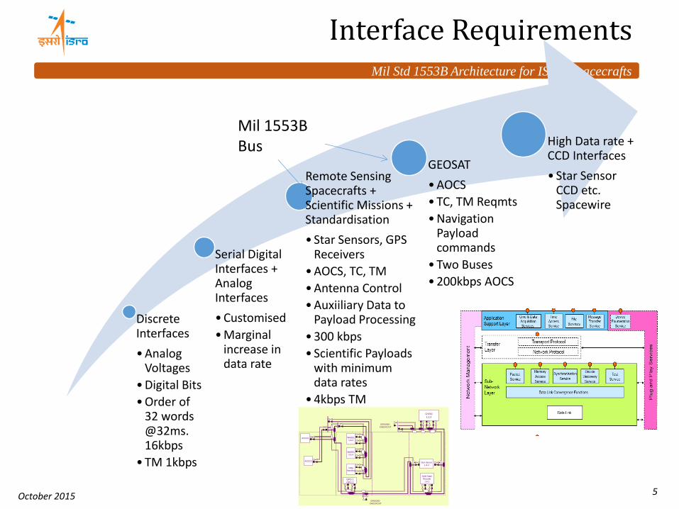
Interface Requirements
Discrete Interfaces
•Analog Voltages
•Digital Bits
•Order of 32 words @32ms. 16kbps
•TM 1kbps
Serial Digital Interfaces + Analog Interfaces
•Customised
•Marginal increase in data rate
Remote Sensing Spacecrafts + Scientific Missions + Standardisation
• Star Sensors, GPS Receivers
•AOCS, TC, TM
•Antenna Control
•Auxiiliary Data to Payload Processing
•300 kbps
• Scientific Payloads with minimum data rates
•4kbps TM
GEOSAT
•AOCS
•TC, TM Reqmts
•Navigation Payload commands
•Two Buses
•200kbps AOCS
High Data rate + CCD Interfaces
• Star Sensor CCD etc. Spacewire
Mil 1553B Bus
`
AOCC1
AOCC2
GPS 1
GPS 2
Star Sensor
1 & 2
Solid State
Recoder
1 & 2
GROUND
CHECKOUT
WHEEL
3 & 4
Data
Handling
WHEEL
1 & 2
GYRO
1,2,3
GROUND
CHECKOUT
Mil Std 1553B Architecture for ISRO Spacecrafts
October 2015 6
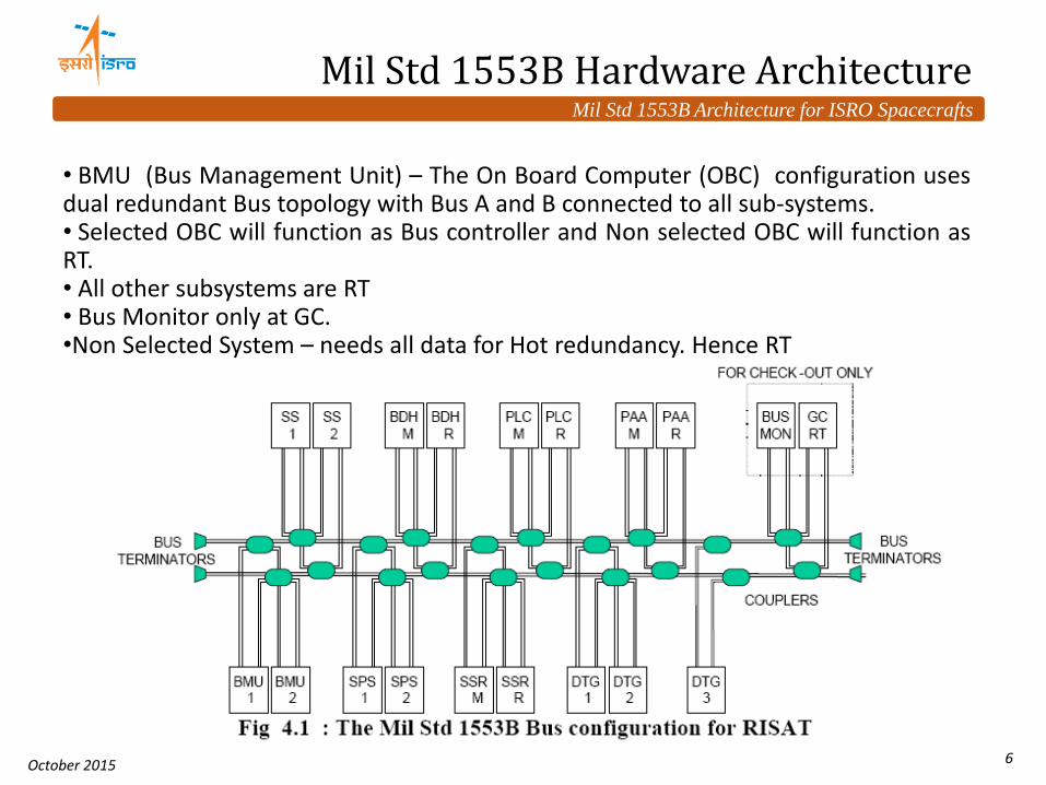
Mil Std 1553B Hardware Architecture
• BMU (Bus Management Unit) – The On Board Computer (OBC) configuration uses dual redundant Bus topology with Bus A and B connected to all sub-systems. • Selected OBC will function as Bus controller and Non selected OBC will function as RT. • All other subsystems are RT • Bus Monitor only at GC. •Non Selected System – needs all data for Hot redundancy. Hence RT

Mil Std 1553B Architecture for ISRO Spacecrafts
October 2015 7
Software Architecture
• Host Software Round-robin
Advantage Simplicity, Deterministic
Short comings Scalability Fragile for code changes Manual partitioning Manual scheduling Multiple cycles – 8ms/16ms/32ms/64ms /128ms/512ms
• Mil 1553 Software
• Should Match Host Software architecture • No Asynchronous Interfaces • Deterministic • Fail Safe • Multiple cycles – 8 to 512ms.
• Should have both BC, RT Functions.

Mil Std 1553B Architecture for ISRO Spacecrafts
October 2015 8
Types of Data Transfer
• Sensors Data
• Actuators Data
• House Keeping Telemetry
• Telecommand
• Payload Data
• Payload Processing Telemetry
• Calibration Data
• Time Synchronisation
• Protocol Handling
• Fault Tolerance
Susbsystems
• Sensors to AOCC
• AOCC to Actuators
• TM, TC to All subsystems
• Payload Transfers
• Non selected AOCC Data transfers
Types of Data Transfer – Functional
Mil Std 1553B Architecture for ISRO Spacecrafts
October 2015 9
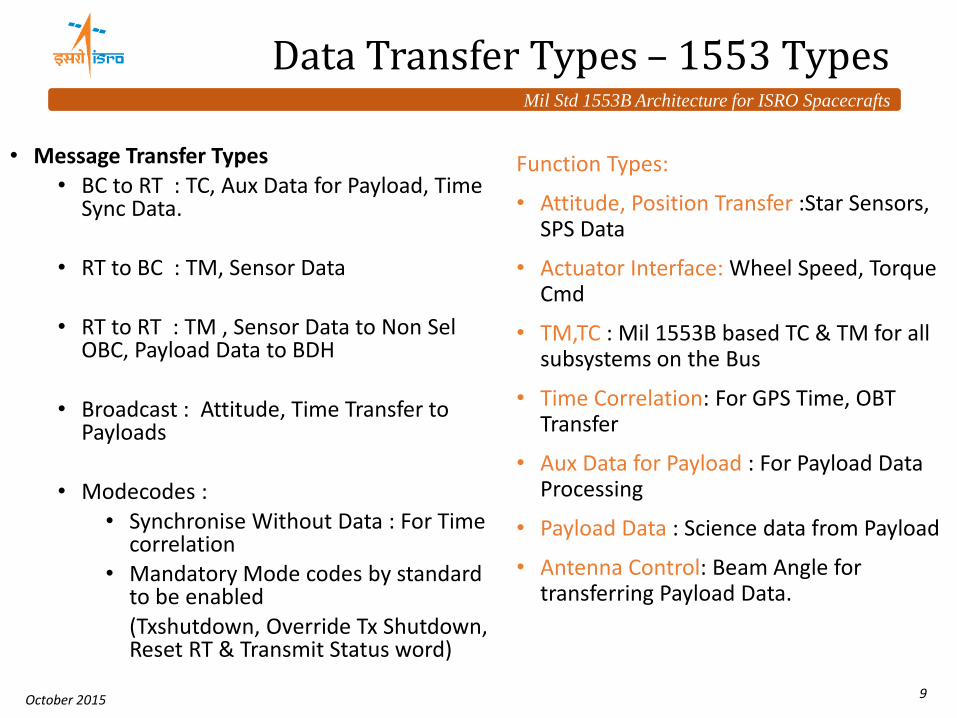
Data Transfer Types – 1553 Types
• Message Transfer Types • BC to RT : TC, Aux Data for Payload, Time
Sync Data.
• RT to BC : TM, Sensor Data
• RT to RT : TM , Sensor Data to Non Sel OBC, Payload Data to BDH
• Broadcast : Attitude, Time Transfer to Payloads
• Modecodes : • Synchronise Without Data : For Time
correlation • Mandatory Mode codes by standard
to be enabled (Txshutdown, Override Tx Shutdown,
Reset RT & Transmit Status word)
Function Types:
• Attitude, Position Transfer :Star Sensors, SPS Data
• Actuator Interface: Wheel Speed, Torque Cmd
• TM,TC : Mil 1553B based TC & TM for all subsystems on the Bus
• Time Correlation: For GPS Time, OBT Transfer
• Aux Data for Payload : For Payload Data Processing
• Payload Data : Science data from Payload
• Antenna Control: Beam Angle for transferring Payload Data.

Mil Std 1553B Architecture for ISRO Spacecrafts
October 2015 10
Types of Interface Services Provided
• TC Service
• Type 1,2,3
• TM Service
• Function, Format Based
• Periodic Data Service
• Critical, Delay Reqmt, Hardware synchronised
• Polled Request Periodic Service
• Data Ready, Data Request I/F
• Asynchronous Message Transfer Service
• Time Sync Service
• Bulk Data Transfer Service
Types of Software Interfaces provided
• Used by: • Time Critical Data => Gyro Sync, Time
Marker
• Periodic => Sensor Data ( like Star sensor) H/w Sync, Auxilliary Data
• Data Ready Driven => Data like GPS Position, Payload Data
• Delay Requirement => Data like Gyro Angle read after Sync
• Asynchronous Data => Telecommand Derived
• Bulk Data => Payload data ( Periodic)
• Bulk Data => asynchronous – Large volume – like Software Patch
Mil Std 1553B Architecture for ISRO Spacecrafts
October 2015 11
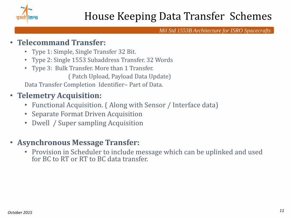
House Keeping Data Transfer Schemes
• Telecommand Transfer: • Type 1: Simple, Single Transfer 32 Bit.
• Type 2: Single 1553 Subaddress Transfer. 32 Words
• Type 3: Bulk Transfer. More than 1 Transfer.
( Patch Upload, Payload Data Update)
Data Transfer Completion Identifier– Part of Data.
• Telemetry Acquisition: • Functional Acquisition. ( Along with Sensor / Interface data) • Separate Format Driven Acquisition • Dwell / Super sampling Acquisition
• Asynchronous Message Transfer: • Provision in Scheduler to include message which can be uplinked and used
for BC to RT or RT to BC data transfer.
Mil Std 1553B Architecture for ISRO Spacecrafts
October 2015 12
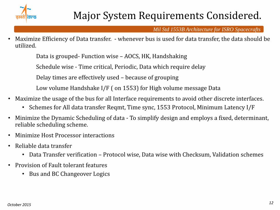
Major System Requirements Considered.
• Maximize Efficiency of Data transfer. - whenever bus is used for data transfer, the data should be utilized.
Data is grouped- Function wise – AOCS, HK, Handshaking
Schedule wise - Time critical, Periodic, Data which require delay
Delay times are effectively used – because of grouping
Low volume Handshake I/F ( on 1553) for High volume message Data
• Maximize the usage of the bus for all Interface requirements to avoid other discrete interfaces.
• Schemes for All data transfer Reqmt, Time sync, 1553 Protocol, Minimum Latency I/F
• Minimize the Dynamic Scheduling of data - To simplify design and employs a fixed, determinant, reliable scheduling scheme.
• Minimize Host Processor interactions
• Reliable data transfer
• Data Transfer verification – Protocol wise, Data wise with Checksum, Validation schemes
• Provision of Fault tolerant features
• Bus and BC Changeover Logics

Mil Std 1553B Architecture for ISRO Spacecrafts
October 2015 13
Bus Profiling
• Architecture Design: Minor Frame (8ms), Major Frame (64ms), Super Frame (512ms)
• Allocation of Bandwidth / Slots for Each Subsystem
• Identify Slots – Critical / Delay / Periodic / Post Delay
• Scheduling – Periodic / Handshake Driven / Asynchronous
• Bulk Message Slots Provisions
• Syncing of Hardware Events with Mil 1553 Cycle
• Compute
• Margins in Each Minor Frame
• Execution Latency
• Minimum / Maximum Delays
Mil 1553B Bus Profiling

Mil Std 1553B Architecture for ISRO Spacecrafts
October 2015 14
• Bus Profiling contd..
• Data Ready and Data Request Messages
• Time Critical - Hence Sampling / handling is periodic
• Data Transfer Messages
• Dictated by Consumption of Message
• Gyro usage before Controller
• Actuator after Controller
• Loop bandwidth requirements
• Periodic Data messages
• Dictated by periodicity
• Source of data / Source Modules
Mil 1553B Bus Profiling contd..

Mil Std 1553B Architecture for ISRO Spacecrafts
October 2015 15
Typical Scheduler Design
• Selected AOCC is BC.
• Non selected AOCC is RT
• Message Table for Each Message
• Grouping of Messages of Each RT.
• Each RT is a component
• Messages divided as • Time Critical
• Periodic
• Asynchronous Messages
• Event Driven Messages
• Bulk Messages
• Fixed Scheduling
• Bulk messages dynamically
scheduled in fixed slots
TCP
Subsystem
Interface Modules
Scheduler
Request Flag
Scheduled Flag
Subsystem
Interface Modules
Request Flag
Scheduled Flag
Main
Frame
Protocol
Chip
Cycle Number
Start Message Wait For Timer End Start Timer End Message
Normally filled with TM, Dwell TM Messages
Critical Slot Post Delay Slot
Main Frame 1
Main Frame 2
Mil Std 1553B Architecture for ISRO Spacecrafts
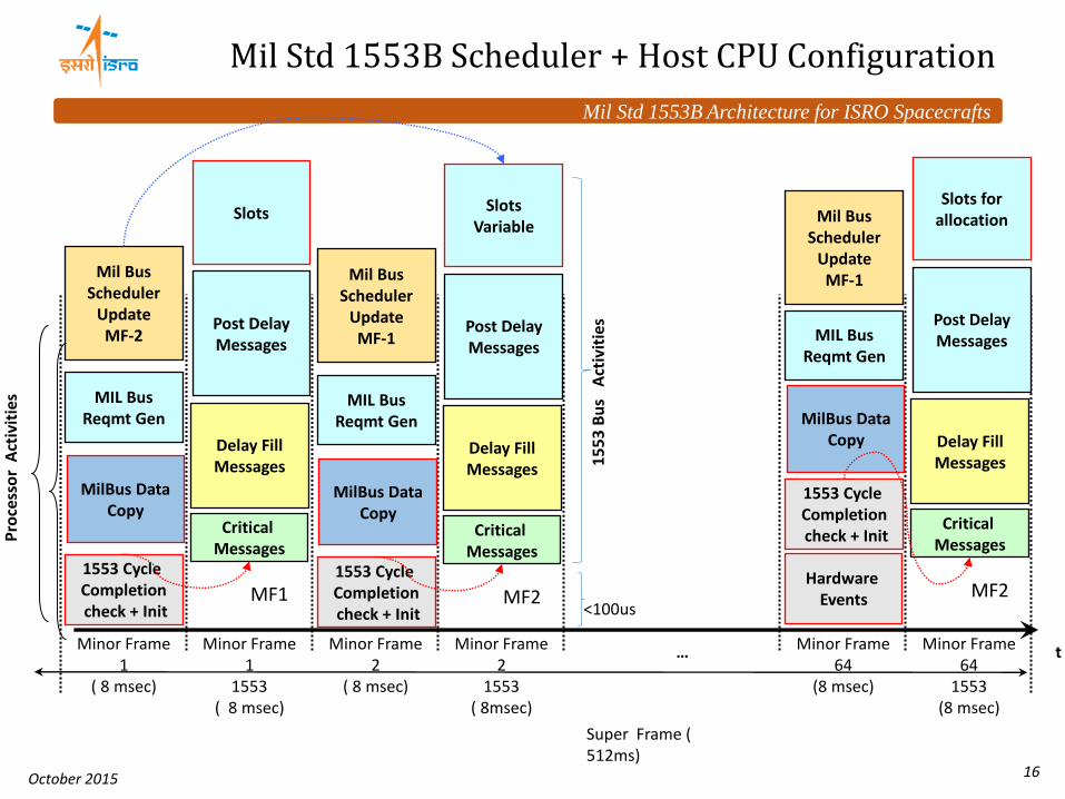
October 2015 16
t
Super Frame ( 512ms)
Minor Frame 1
( 8 msec)
Minor Frame 1
1553 ( 8 msec)
1553 Cycle Completion check + Init
Critical Messages
Minor Frame 2
( 8 msec)
Minor Frame 64
1553 (8 msec)
Slots
Mil Bus Scheduler
Update MF-2
Post Delay Messages
MilBus Data Copy
Delay Fill Messages
Minor Frame 2
1553 ( 8msec)
Minor Frame 64
(8 msec)
…
MIL Bus Reqmt Gen
Pro
cess
or
Act
ivit
ies
MF1 1553 Cycle Completion check + Init
Critical Messages
Slots Variable
Mil Bus Scheduler
Update MF-1
Post Delay Messages
MilBus Data Copy
Delay Fill Messages
MIL Bus Reqmt Gen
MF2
1553 Cycle Completion check + Init
Critical Messages
Slots for allocation Mil Bus
Scheduler Update MF-1
Post Delay Messages
MilBus Data Copy Delay Fill
Messages
MIL Bus Reqmt Gen
MF2 Hardware
Events 1
55
3 B
us
Act
ivit
ies
<100us
Mil Std 1553B Scheduler + Host CPU Configuration

Mil Std 1553B Architecture for ISRO Spacecrafts
October 2015 17
Mil 1553B Typical Interfaces
Interfaces Provided
• Data
• Message Transfer Requirement
• Message Service Flag
• Message Error Flag
• Time of Message Information
• Bus Used Flag
• Transfer Status

Mil Std 1553B Architecture for ISRO Spacecrafts
October 2015 18
Functions Implemented in OBC
• Selected OBC Functions as Bus Controller
• Bus Controller Functions
• Message Transfer Requirement Generation
• Message Scheduler
• Message Transfer Verification
• Data Copy to Respective interface data
• Bus Selection and Bus Changeover Logic for each RT
• TC,TM
• FDIR
• Data Transfer is initiated every minor cycle by OBC Software
• Messages to be initiated are decided by respective interface modules.
• Non Selected OBC functions as RT
• RT functions
• Message Transfer verification
• Bus Selection
• TC, TM
• Time of Message Transfer
• Bulk Message Handling
• Handling Asynchronous Sampling
• Double Buffering
• Common Functions
• Refresh RAM operations
• Register Refresh Operations
• Initialisation
• System Changeover Logics

Mil Std 1553B Architecture for ISRO Spacecrafts
October 2015 19
OBC OFF
Init Mode
RT Mode BC
Mode
OBC On
OBC Not Selected
OBC Selected & BC Delay Over
MIL STD 1553B Modes of AOCE
OBC Changeover
OBC Changeover
BC Delay Not Over
No OBC Changeover
No OBC Changeover
Power On Init
Power On Init Over
OBC System or Processor Reset
States in OBC Major Cycle
BC,RT Initialisation – OBC Changeover

Mil Std 1553B Architecture for ISRO Spacecrafts
October 2015 20
Time Sync Interfaces 1. Marker From Time Source / User
Hardware / Mil 1553 Marker ( PPS, Sync Mode Code)
2. Time at Marker from Time Source
• Time Sync – By Marker followed by Onboard Time
• Time sync – applicable for both - OBC to subsystem or GPS receiver to OBC
• Marker – Discrete I/f like PPS / 1553 Message though Sync without data Mode command
• Time sync message types – RT Based
Broadcast Based – single / alternate Bus
• TT Register is kept track w.r.t On Board Time – For monitoring all messages and events.
Time Sync Schemes
Time Tag register
Marker Syn c
Time sync accuracies in the order of 100us.
Mil Std 1553B Architecture for ISRO Spacecrafts
October 2015 21
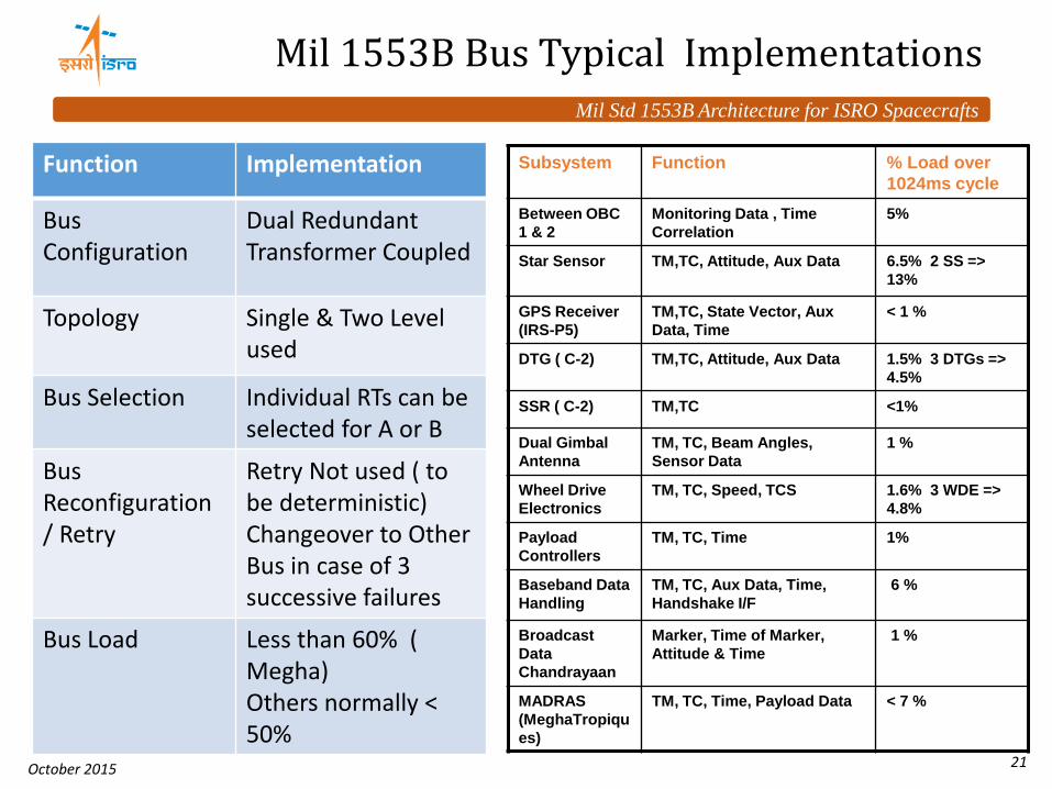
Mil 1553B Bus Typical Implementations
Function Implementation
Bus Configuration
Dual Redundant Transformer Coupled
Topology Single & Two Level used
Bus Selection Individual RTs can be selected for A or B
Bus Reconfiguration / Retry
Retry Not used ( to be deterministic) Changeover to Other Bus in case of 3 successive failures
Bus Load Less than 60% ( Megha) Others normally < 50%
Subsystem Function % Load over
1024ms cycle
Between OBC
1 & 2
Monitoring Data , Time
Correlation
5%
Star Sensor TM,TC, Attitude, Aux Data 6.5% 2 SS =>
13%
GPS Receiver
(IRS-P5)
TM,TC, State Vector, Aux
Data, Time
< 1 %
DTG ( C-2) TM,TC, Attitude, Aux Data 1.5% 3 DTGs =>
4.5%
SSR ( C-2) TM,TC <1%
Dual Gimbal
Antenna
TM, TC, Beam Angles,
Sensor Data
1 %
Wheel Drive
Electronics
TM, TC, Speed, TCS 1.6% 3 WDE =>
4.8%
Payload
Controllers
TM, TC, Time 1%
Baseband Data
Handling
TM, TC, Aux Data, Time,
Handshake I/F
6 %
Broadcast
Data
Chandrayaan
Marker, Time of Marker,
Attitude & Time
1 %
MADRAS
(MeghaTropiqu
es)
TM, TC, Time, Payload Data < 7 %

Mil Std 1553B Architecture for ISRO Spacecrafts
October 2015 22
Processor or Eqvt Logic
Typical Hardware Implementation
Shared RAM
Mil Std 1553B Protocol Controller
BC/RT RT Addr 1553 A/B
Memory Arbitration Logic
Local PROM, RAM,I/O
Low Latency I/O Through 1553 Transceiver
+Transformer
Bus A, B
Reset Clock
• Processor Based • Non Processor Based Systems • Protocol controller Memory mapped • Two level Topology requires two protocol controllers • Protocol Controller chip based • IP Core – based • External RAM to Controller • upto 8KW of Shared RAM • With Built in / External Transceiver • Tansceiver, Transformer with 5V, 15V, 3.3 V options

Mil Std 1553B Architecture for ISRO Spacecrafts
October 2015 23
Typical Implementations – SAR Payload Controller Interface

Mil Std 1553B Architecture for ISRO Spacecrafts
October 2015 24
SAR Payload Controller Interface - Contd..

Mil Std 1553B Architecture for ISRO Spacecrafts
October 2015 25
Interface Safety Features
• Major Requirements:
• Data Transfer Consistency
• Functional Consistency
• Communication Verification
• Means:
• Parity Bits in I/f
• Wild sample remover
• Validation of at least 3 consecutive samples for taking critical action
• Checksum in Packet Transfers
• Validation with Other sensors
• Valid / Invalid bit provision in I/f
• Communication Validation.
Consistency of Data ensured by • Data Ready logic – Sampling + Delay requirements
• Checksum in all critical packets
•If synchronised with hardware, scheduler profile sync with hardware. Periodic Forced Sync.
•Double buffering if required

Mil Std 1553B Architecture for ISRO Spacecrafts
October 2015 26
Fail Safe Logics
• RAM Refresh
• Periodic refresh of Protocol logic pointers
• Register Refresh
• Protocol registers are initiated every cycle.
• Bus Fault Detection logics
• Bus Changeover Logics
• Successive 3 Fail cycles changes Bus for the RT
• RT FDIR : Further 3 successive Fail cycles declare RT failure after changeover.
• Detection of BC failure – for 2 selected RTs results in BC changeover - by declaring Safe Mode.
• FDIR for subsystems / Payloads
• No Retry used. Auto Bus changeover logic is expected to Act
• Heart Beat timers are provided in periodic readout ( TM). Incase of freeze, shutdown actions are initiated.
• In addition, Payload can request shutdown, in case it finds wrong sequence or anomaly.
• Onboard Diagnostics • 1553 Cycle Completion Error
Checks and Diagnostic counters
• Interface Fail Error Counters
• Mil 1553 Bus Error checks and Fail counters
• Real Time Executive - Scheduler – Time overrun Indicators
• Message Status, Bus Status of Mil 1553B
Mil Std 1553B Architecture for ISRO Spacecrafts
October 2015 27
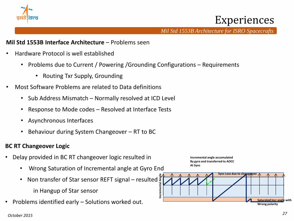
Mil Std 1553B Interface Architecture – Problems seen
• Hardware Protocol is well established
• Problems due to Current / Powering /Grounding Configurations – Requirements
• Routing Txr Supply, Grounding
• Most Software Problems are related to Data definitions
• Sub Address Mismatch – Normally resolved at ICD Level
• Response to Mode codes – Resolved at Interface Tests
• Asynchronous Interfaces
• Behaviour during System Changeover – RT to BC
Experiences
BC RT Changeover Logic
• Delay provided in BC RT changeover logic resulted in
• Wrong Saturation of Incremental angle at Gyro End
• Non transfer of Star sensor REFT signal – resulted
in Hangup of Star sensor
• Problems identified early – Solutions worked out.
Sync Loss due to changeover
Incr
em
en
tal A
ngl
e
Incremental angle accumulated By gyro and transferred to AOCC At Sync
Saturated Incr angle with Wrong polarity

Mil Std 1553B Architecture for ISRO Spacecrafts
October 2015 28
Scheduler Effects
• Correlator was getting reset with Mil Std 1553B Interface in GPS Receiver.
• Flight Scheduler schedules all messages together once Data ready is received.
• Always the Receiver was tested with 1 msg at a time.
• Early Interface Test with BC Scheduler identified the Issue and correction carried out at GPS
• Database Driver Scheduler + Schemes are provided for BC simulators.
64ms
Data Rdy Sampling
SPS State vector
Measurements Reading
Sync Command
Time sync Reading 1 sec
1 min
< 1 sec Read State Vector
Measurements
SL, NS OBC
Experiences contd..

Mil Std 1553B Architecture for ISRO Spacecrafts
October 2015 29
Conclusion & Future.
• Mil Std 1553B Bus has been effectively used for various ISRO spacecraft Applications.
• Typical requirements of AOCS & other applications have been captured and used.
• Present Monolithic configuration with service functions needs to be migrated to more Layered architecture.
• Requirements with multiple 1553 Bus topologies for isolation reqmts are provided.
• Also other interface requirements are being increasingly envisaged at various levels, i.e Spacewire, CAN Bus, I2C at Lower level.
• CCSDS –SOIS is to be considered for the advantages of mixing multiple interface standards, multiple sources and including Multiple Processors in future.

Mil Std 1553B Architecture for ISRO Spacecrafts
October 2015 30
Acknowledgements are Due to • Dr. A S Kiran Kumar, Chairman ISRO • Dr. M Annadurai, Director ISAC • Mr. Subramanya Udupa, DD, CDA, ISAC • Colleagues and Team members of Control and Digital Electronics Group, Sincere thanks to • Dr. Allen D Unell, Chairman FSW-2015 • Mr. Subodh Harmalkar, FSW-2015, APL