milk mixer - messiah mixer final report submitted by: ... to build a system that required only four...
TRANSCRIPT

MMiillkk MMiixxeerr FFiinnaall RReeppoorrtt
Submitted by: Steve Forry Chris Jones Dan Tyson
Advisor:
Dr. Timothy Van Dyke
4/30/02

Abstract
In the past, the process for mixing powdered milk with water to feed calves
has required manual labor or expensive mixing equipment. The manual mixing
process is time consuming, as it requires the ingredients to be loaded, mixed, and
dispensed manually. This process also includes manual cleaning of the equipment.
Motorized mixing equipment is often unaffordable for the average farmer. In
addition, many mixing systems on the market are motorized, which reduces manual
input, but they still require manual loading of the ingredients.
The purpose of this project was to design and construct a mixing system that
is time saving and affordable for the average farmer. The project consisted of
building an apparatus to dispense measured amounts of powder and water to be
mixed for a specified number of animals. In addition, a washing device was
assembled. Also included in the project was the implementation of a microcontroller
that serves to control the entire mixing process. This mixing system improves upon
most available systems in that it automates the entire mixing process from the
loading of the ingredients to the dispensing of the product and the sanitizing of the
apparatus.
2

ABSTRACT ......................................................................................................................2
INTRODUCTION............................................................................................................4
DESCRIPTION ..................................................................................................................4 Objectives...................................................................................................................4
LITERATURE REVIEW .....................................................................................................5 SOLUTION .......................................................................................................................8
Our Solution ..............................................................................................................8 Alternative Solutions ...............................................................................................11
DESIGN PROCESS ......................................................................................................13
ANALYSIS/EXPERIMENTAL WORK................................................................................13 DESIGN .........................................................................................................................14
Mechanical...............................................................................................................14 Electrical..................................................................................................................17
IMPLEMENTATION ...................................................................................................18
CONSTRUCTION.............................................................................................................18 Mechanical: .............................................................................................................18 Electrical..................................................................................................................21
OPERATION ...................................................................................................................22
SCHEDULE....................................................................................................................25
PROJECT MANAGEMENT ...............................................................................................25 GANTT CHART..............................................................................................................26 SCHEDULE CHANGES....................................................................................................26
BUDGET.........................................................................................................................27
CONCLUSION ..............................................................................................................28
RECOMMENDATIONS FOR FUTURE WORK ....................................................29
REFERENCES AND BIBLIOGRAPHY....................................................................30
Internet.....................................................................................................................30 Books........................................................................................................................31 Pamphlets.................................................................................................................32
3

INTRODUCTION
Description
The original milk mixing process was a completely manual procedure. All of the
measurements were done by hand, as well as the milk dispensing and washing.
Because of this, the process was very time consuming. In addition, the ingredient
measurements were not very precise resulting in a milk mixture with improper
proportions.
The goal of this project was to design and construct a system that combines and
blends water and milk powder (known as Milk Replacer) to create milk that is
suitable for feeding calves. The system included automation of the following:
measurement of raw materials, the mixing process, dispensing of finished product,
and washing of the mixing equipment.
The need, therefore, was for a solution, which would be less labor intensive, less
time consuming and more precise. In addition, the solution would be user friendly
and low cost, thus making it affordable and practical for the small-scale farmer.
Objectives
1. To build a system that had a mixing capacity of at least 50 animals per batch
(25 gallons).
2. To build the complete system for under $500.
4

3. To build a system that required only four manual procedures:
(1) Input the number of calves.
(2) Input the time of mixing.
(3) Dump the milk powder into the bin.
(4) Dispense the final product.
4. To design a program for the MK11 microcontroller that did not require
computer literacy to operate, and house the controller within a NEMA Type 4
enclosure.
5. To construct a system that had a mixing time of less than five minutes and
total process time of less than fifteen minutes.
Literature Review
Mixing systems are integral parts of many manufacturing processes. They are used
in pharmaceutical companies, dairy processing plants, chemical manufacturing, and
many other applications. However, the majority of these systems are intended to
handle large quantities of material and therefore are unsuitable for small-batch
mixing.
Small self-contained blending systems are available through custom fabricating firms.
These systems are typically constructed of stainless steel and use high-tech blending
techniques. Many companies offer complete blending systems or the particular parts
of a system. Many of these products are designed specifically for a particular task.
5

JBW Systems, Inc. sells a product called the JBW Mixing System. This system is a
light self-contained unit, which is suitable for small quantities of powder-in-liquid
mixing. However, the proportions of liquid and powder must be manually placed in
the mixer.
Flo Trend Mixing Systems manufactures a system called Jet Shear II. This tank-free
device utilizes unique nozzles to create a flow pattern in order to blend two
materials. However, this system is not designed to mix solids in liquids and does not
incorporate a metering system for the ingredients.
TSPF Heifer Services, a subsidiary of AGWAY Inc., mixes the milk for their calves
in an open-topped stainless steel tank. The water is supplied from a water heater and
the volume is monitored via an inline flow meter. The powder is measured and
poured into the mixing tank by the operator. The actual mixing is accomplished by
an impeller mounted, via a stainless steel shaft, to a variable speed motor mounted at
the top of the tank.
In the past 30 years, the microcontroller has become an integral part of the world of
automation and control. The microcontroller is a relatively recent development that
has branched off the larger PLC’s (programmable logic controllers). In the late
1970’s, several years after its introduction, the PLC market was around $80 million.
By 1990, with more affordable computer hardware and a higher level of capabilities,
6

the market for PLC’s grew to $1 billion and it continues to increase exponentially to
this day (Webb 5). Today, PLC’s are used in most manufacturing industries as
process controllers, as well as in building energy and security control systems. As
PLC’s continue to get smaller and smaller, the uses for them continue to grow.
Many leading automation and control companies have already developed
microcontrollers. Allen-Bradley and Rockwell Automation have a microcontroller on
the market called the Pico Controller. This small controller performs simple logic,
timing, counting, and real-time clock operations. Although the Pico Controller was
designed for ease-of-use without any programming software, it still requires
knowledge of logic functions and data input to program and run the controller.
GE-Fanuc also has several microcontrollers on the market called the Versamax Micro
and Nano PLC’s. These PLC’s are also small and perform the same functions as a
larger PLC, but programming software is required, which in turn requires extensive
knowledge of programming logic. These units are not cheap; a small Nano PLC
with an operator interface can cost well over $500.
Various other companies have developed microcontrollers such as Modicon
(Schneider Automation) and Square D. These controllers can be quite expensive and
the user interface is such that one needs knowledge of programming logic.
7
From our research we concluded that there was not anything quite like what we were
looking for available on the market. A few of the systems had parts that we liked,
but none of them that we found did the complete process and all of them were more
costly than what we were looking for.
Solution
Our Solution
Our solution sought to fix some of the problems that we saw with the technology
available on the market. We wanted to build a system that was entirely automated
and effectively mixed the milk, but was not high priced.
Regarding the mechanical areas of this project, the action items of concern included
the following:
1) Water was metered to ensure that the appropriate quantity was dispensed
for each batch of milk. This was monitored by timing the flow at a
known flow rate (gpm). A solenoid valve was installed in the water inlet
line to control the flow.
2) An auger was used as a powder-metering device to ensure that the
appropriate quantity of powder was mixed with water. In addition, the
auger was utilized to transport the powder from the holding bin to the
mixing tank. The appropriate quantity of powder was dispensed by
monitoring the running time of the auger.
8

3) The mixing was performed in a thirty-gallon barrel and utilized an
impeller to do the mixing. This impeller was mounted on a vertical shaft
connected to an electric motor, which was mounted at the top of the tank.
4) The impeller was selected to ensure that the shear in the mixture was great
enough to completely mix the powder in the water (e.g. no lumps larger 1-
mm). The impeller was machined from aluminum for corrosion resistance.
5) A solenoid valve was installed on the mixing tank outlet line to enable the
controller to measure the appropriate quantity of milk for each calf (1/2
gallon). In addition, this valve was programmed to open at the end of the
wash and rinse cycles to allow the water to drain from the mixing tank.
6) Soap was dispensed into the mixing tank, during the wash cycle, by
utilizing a detergent container mounted over the mixing tank. The amount
of detergent that drained into the tank per wash cycle was controlled by a
solenoid valve.
The electrical portion of the project consisted of programming a microcontroller,
which controlled the following items:
1) At the time designated by the user, the controller began the process by
opening the water inlet valve.
2) The controller used timing based on the flow rate until the appropriate
quantity of water entered the mixing tank, at which time the controller
closed the valve.
9

3) The controller was integrated with the powder dispensing process in the
following manner:
a) The controller started the powder measuring process by turning on
the auger after the water had entered the tank.
b) Using a timer, the controller ensured that the auger dispensed the
appropriate quantity of powder into the tank.
4) When the proper quantities of powder and water were in the mixing tank
the controller initiated the mixing process by starting the motor. The
motor ran for a predetermined amount of time (until all of the powder was
suspended in the water) at which time the controller turned the motor off.
5) The controller was programmed to open the outlet solenoid valve for a set
amount of time (long enough for ½ gallon of milk to be released) when a
button is pressed on the keyboard.
6) When all of the milk was drained from the mixing tank, the controller
initiated the washing process and dispensed the detergent and water into
the tank. At the completion of the cycle, the controller opened the outlet
valve to allow the tank to drain.
The only input that the user needed to perform was: the number of animals that were
to be fed and dispensing the milk at the end of the mixing cycle. The temperature of
the water inflow did not need to be controlled by the microcontroller because it was
set to the appropriate temperature at the hot water heater.
10

Alternative Solutions
There were other alternatives that we looked at during the design phase of the
project. First, there was a question of whether to use an inline mixer or a rotating
agitator. The inline mixer had the advantage of not having moving parts, but it had
a major drawback in that it was very difficult to clean so we decided that a rotating
agitator was better for our project.
Second, for the powder measurement we thought of using a dumping hopper, which
utilized load cells, to determine the weight of the powder in the hopper. The
controller would have determined how much weight of powder was needed for a
particular number of calves, weighed that quantity, and dumped it into the tank.
However, this idea seemed to be much more complex than using an auger and had a
greater potential for problems. In addition, the load cells would have been expensive
and difficult to manipulate.
Third, the detergent was originally going to flow into the water line via a drip line
and from there it would enter the tank. However, this design had several drawbacks.
There was the problem of knowing how much detergent was dispensed. In addition,
it did not seem like a good idea to have the detergent flow through the same line
that the water flowed through that was used for the milk.
11

Fourth, for the impeller and shaft we had to decide whether to use aluminum or
stainless steel. Stainless steel was ruled out because of cost and problems associated
with welding and machining. However, if we had bought a pre-assembled shaft and
impeller, stainless steel would have been the preferred material.
Fifth, a stainless steel mixing tank would have been ideal, but because of our
monetary constraints we chose plastic because it was much cheaper. In addition, it
was easier to make modifications to the plastic drum than it would have been for a
stainless steel drum.
Sixth, our original design called for us to design and build the entire microcontroller.
However, we decided that it would be better use of our time to program a controller
than to build one.
Seventh, we could have bought a commercial microcontroller to control the system
such as the Allen Bradley Pico Controller. However, the high cost of these types of
controllers was out of our budget range.
12
Design Process
Analysis/Experimental Work
Our experimentation and analysis included five specific tests that were conducted
during and after the construction of the mixing system. These tests were as follows:
1) We measured the flow rate of the incoming water from the hot water
heater to the mixing system. The experimentation was done by utilizing a
five-gallon bucket and a stopwatch. The procedure was repeated five
times to yield a mean flow rate.
2) We experimented with the mixing time until we found the optimal
duration for obtaining the most homogeneous mix. This was accomplished
by using the motor, impeller and tank, which were used in the final
prototype. Tests were performed for various batch sizes to ascertain the
required time for the mixing process. To measure the homogeneity of the
milk mixture a cheese cloth was used to measure the quantity and size of
any lumps remaining in the milk.
3) We analyzed the weight that the load bearing structure needed to withstand
and designed the structure accordingly. This was particularly important for
the structure, which supported the mixing tank. This structure was
analyzed on paper using static analysis. The expected load included the
maximum amount of water and milk, which, could be in the tank, as well
13
as the weight of an average person. This was to ensure that the frame
would be able to withstand someone standing on the frame.
4) We tested the programming of the microcontroller by hooking up LED’s
that would indicate when each controlled entity was operating.
5) We tested the functionality of our relay board by hooking up the power
supply and the solenoid valves to ensure that each relay circuit operated
properly. This required the use of a multimeter to check for proper
currents and voltages.
Design
Mechanical
The mechanical aspects of the design included: mixing tank, powder holding bin,
powder dispensing auger, solenoid valves, impeller, mixing motor, motor mount,
impeller shaft, supporting structures, and water piping (See Appendix I,A).
To construct the mixing tank the top was cut off of a used 30-gallon plastic drum.
In addition, a 3/4-inch hole was drilled in the center of the bottom of the drum and
the outlet pipe was attached in that hole. The drum was supported in a stand
constructed of angle iron and steel strips (See Appendix I,B).
The powder holding bin consisted of a fifteen-gallon plastic drum (See Appendix
14

I,F). The top and bottom were cut off of the bin and the top was replaced with a
rubber gasket to seal the top from moisture. A funneling device was constructed
from Plexiglas to direct the flow of the powder from the bin into the lower end of
the auger.
The powder-dispensing auger was donated by a local farmer and was powered by a
single-phase, ½ horsepower, 120 Volt, AC motor, which will operate at 1725
revolutions per minute (See Appendix I,G). The motor ran through a reducing
gearbox so that the powder flow was slow enough for the controller to precisely
measure the powder.
Three solenoid valves were used in the mixing system. One was placed on the water
inlet pipe to allow the appropriate amount of water to enter the tank. Another
controlled the flow out of the tank. The third dispensed the detergent into the water
during the washing process. All of these valves were placed on timers in the
controller and opened and closed at the direction of the controller. In this manner,
the controller was able to dispense the desired amounts of liquid at the appropriate
times.
The impeller was constructed of aluminum because of its cost and durability. The
diameter of the impeller was determined to be at least 1/10th of the diameter of the
tank. The design was simple and resembled a fan blade. There were two blades on
the impeller offset at 180° and set at 30° from the horizontal (See Appendix I,E).
15

Originally, the design called for us to purchase an aluminum or plastic fan blade and
use it for the mixing process, but during initial mixing testing we found that these
blades did not have the structural integrity needed to mix the water. Therefore, we
determined that we needed to build our own impeller from heavier aluminum.
The impeller was connected to the motor via a ½” X 2' shaft. This shaft was pinned
to the hub of the impeller and connected to the motor with a flange and bolts. The
shaft was constructed of aluminum as well because of its resistance to corrosion.
The mixing motor was a single-phase, 1/3 horsepower, 120 Volt, AC motor, which
operated at 1740 revolutions per minute. The motor was mounted at the top of the
tank through the use of a mounting bracket and was angled at 5 degrees from
vertical. The motor mount was made of steel and bolted to the mixing tank stand.
Piping for the water consisted of 1/2-inch PVC and brass and was glued at the
appropriate places. One pipe was run from the water heater for the clean water.
The dispensing piping was attached to the bottom of the mixing tank by utilizing a
bolt-on pipe flange. A horizontal section of PVC was run from under the tank to
make it easier for the user to place a bucket under the end of the pipe.
The detergent container was made of 4-inch clear PVC and was placed vertically
above the mixing tank. The detergent ran from the container through the solenoid
valve and into the tank (See Appendix I,H).
16

Electrical
The components for the electrical aspects of this project consisted of a NEMA Type
4 enclosure (Appendix I,L), a microcontroller that implemented the Motorola 68HC11
microprocessor (Appendix I,M), a relay board (Appendix I,N), a keyboard for data
entry, and an LCD to view data (Appendix I,L). The inputs to the microcontroller
included the keyboard, a system on/off switch, and an emergency cut pushbutton.
The outputs included the motors and the solenoid valves.
Several programs needed to be written for the microcontroller to perform its designed
processes. First, a program was written that responded to the on/off switch and
turned the microprocessor, LCD, and keyboard on and off. Then, a program was
written that required the input of the number of calves, which were to be fed. It was
assumed that for every calf fed, there needed to be a half-gallon of the milk solution
dispensed. Of course, there was a separate program or subroutine to convert from
decimal to hexadecimal. The program calculated the time needed to dispense the
correct proportion of water, which was based on the number of calves entered. The
powder dispensing was done using a timer to control the amount of time that the
auger operated. The quantity of power was predetermined by the input of the
number of calves. The mixing time was also predetermined by the number of calves.
The washing program was a set program that was not dependent on any variables.
This used the timer once again to dispense a specific amount of hot water and soap
17

solution. The flow charts for the preceding programs can be seen in Appendix I,I-K.
There was also an emergency cut pushbutton that sent an input to stop all processes
when depressed.
Implementation
Construction
Mechanical:
Impeller: The impeller was constructed of 1/8” thick aluminum plate in conjunction
with a 1” O.D. aluminum hub with an I.D. of ½”. The impeller was a two-blade
design with the blades 180° from each other. The blades were angled at 30° from
horizontal and welded in slots on the hub using a TIG welder. The blades were
1.25” wide and 2” long. The slots in the hub were cut with a milling machine.
Impeller Shaft: A 2’ long by ½” diameter aluminum rod was used as the shaft for
the mixing operation. One end of the shaft was fastened in the impeller hub by
utilizing two stainless steel pins. The upper end of the shaft was linked to the motor
shaft by using a coupler secured with bolts (See Appendix I,C).
As previously mentioned, the initial impeller design did not include the machining of
an impeller, but through testing we found that it was necessary to design and
construct an aluminum impeller from a heavier material.
18

Mixing Tank: The top of the 30-gallon drum was removed and a 3/4” hole was cut
in the bottom for the drain pipe. One-half inch diameter brass pipe was placed in the
hole in the bottom of the tank, and was held in place using a flange.
Powder Auger: A three-inch auger encased in thick-walled PVC was used for the
powder transfer and measurement. The total auger length was 4’ and the flighting
length was 3.5’. An eight-inch long section of the auger casing was removed from
the top at the lower end of the auger. This was to allow for the powder entry into
the auger by gravity flow. The powder existed the auger via a cut in the bottom of
the casing near the upper end of the flighting.
The powder auger was fastened to the reducing gearbox by utilizing a pin through
the shaft. The output shaft of the gearbox was machined to fit inside the hollow
auger shaft. However, the set screws that were designed to hold the shaft in the
gearbox were unable to withstand the axial loading and the torque from the auger.
Therefore, it was necessary to drill a hole and replace the set screws with a pin.
Powder Storage Bin: The top and bottom of the 15-gallon plastic drum were
removed. A hinged lid was constructed to seal the top and allow the user to fill the
storage bin. A funneling device was constructed from Plexiglas to funnel the powder
into the auger. The Plexiglas proved challenging to cut and resulted in small cracks
near the edges of the cut pieces. Because of the difficulty in the cutting process the
pieces of the funneling device did not meet at well as they should have and small
openings resulted. However, all of the seams were filled with Lexel caulking which
19

effectively filled the gaps and provided structural integrity to the entire funneling
device. Wooden bracing was added to render additional structural integrity and to
keep the top-heavy bin from toppling over under the weight of the powder.
Design Changes: The original design called for the use of a plastic or aluminum fan
blade to be used as the mixing impeller. These were to be purchased at a low cost
and would have saved manufacturing time. However, initial testing with the 3-4” fan
blades proved that they were unable to withstand the forces involved in the mixing
process.
After initial testing of the final impeller design it was determined that the original
shaft length was too long (3 feet). The shaft deflections were dramatic because of
the transverse loading at the impeller and the long moment arm (the shaft). To
reduce this effect the shaft was shortened by 33%.
The preliminary design for the powder auger utilized a motor connected direct drive
to the auger. The motor was geared down so that its shaft speed was 4 rpm.
Testing proved that this speed was insufficient to transport the required amount of
powder in the allotted amount of time. Using another motor connected through a
gearbox to the auger solved this problem.
20

Electrical
Relay Board: A relay board needed to be built that would receive the signals from
the controller and turn each component on and off. This used 5 similar circuits each
consisting of 2 resistors, 1 transistor, 1 relay, 1 diode, and 2 connectors. Wire leads
were soldered to connect the electrical components. The circuits were mounted onto
a pre-drilled PCB board. See Appendix I,D for circuit schematic.
Enclosure: The controller and relay board were protected using a stainless steel
NEMA Type 4 enclosure. This was prepared by drilling holes to mount the
microcontroller and relay boards to the grounding plate of the enclosure. Holes were
also cut in this casing to allow the keyboard and LCD to be connected to the
controller. In addition, two holes were drilled to allow the connection of PVC
conduit. The 24 VAC transformer was mounted inside the enclosure and the power
supply for the microcontroller was mounted on the outside wall of the enclosure.
The LCD was mounted on the face of the enclosure and was encased with Plexiglas
to protect it.
Connection: The various motors and solenoid valves were wired to the controller
through PVC conduit channels.
21

Operation
Testing began with the determination of the water flow rate into the mixing tank.
After a series of tests the mean flow rate was determined to be 5.21 gallons per
minute.
Test # Amount of Water (Gallons)
Time (Seconds) Rate (GPM)
1 1.25 13 5.77
2 1.25 12 6.25
3 1.25 13 5.77
4 5 63 4.76
5 5 72 4.17
6 5 66 4.55
Average 5.21
The powder auger was tested by placing a bucket underneath the powder exit to the
amount of powder that flowed from the auger per time. The test was conducted four
times and the results averaged to find a resultant mean powder flow rate. It was
determined that the mean powder flow rate was 9.11 cups per minute.
22
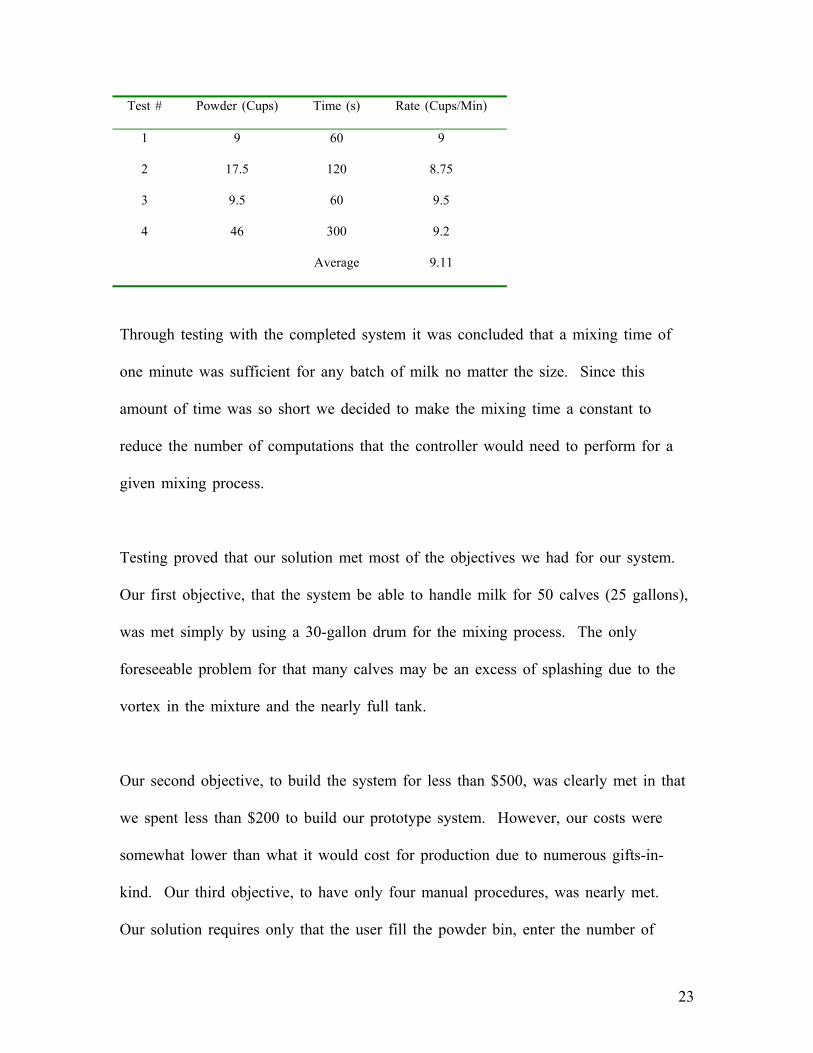
Test # Powder (Cups) Time (s) Rate (Cups/Min)
1 9 60 9
2 17.5 120 8.75
3 9.5 60 9.5
4 46 300 9.2
Average 9.11
Through testing with the completed system it was concluded that a mixing time of
one minute was sufficient for any batch of milk no matter the size. Since this
amount of time was so short we decided to make the mixing time a constant to
reduce the number of computations that the controller would need to perform for a
given mixing process.
Testing proved that our solution met most of the objectives we had for our system.
Our first objective, that the system be able to handle milk for 50 calves (25 gallons),
was met simply by using a 30-gallon drum for the mixing process. The only
foreseeable problem for that many calves may be an excess of splashing due to the
vortex in the mixture and the nearly full tank.
Our second objective, to build the system for less than $500, was clearly met in that
we spent less than $200 to build our prototype system. However, our costs were
somewhat lower than what it would cost for production due to numerous gifts-in-
kind. Our third objective, to have only four manual procedures, was nearly met.
Our solution requires only that the user fill the powder bin, enter the number of
23

calves, fill the detergent container and dispense the milk into the buckets by pressing
enter on the keyboard and rotating the buckets beneath the dispensing pipe. The
detergent filling was added to the manual processes and the internal clock was not
incorporated in the system to allow the user to enter the desired time of day for the
mixer to operate.
Our fourth objective, to use a controller that does not require computer literacy to
operate and to house it in a NEMA Type 4 enclosure, were met by programming the
controller to prompt the user for inputs through simple menus. The entire
microcontroller was housed in a sealed steel enclosure to protect it from moisture
damage.
The final objective, to have a mixing time of less than five minutes and a process
time of less than fifteen minutes, was not quite met. The mixing time proved to be
much less than the five minutes that we allowed for, but the powder dispensing, milk
dispensing and washing cycles occupied the remainder of the fifteen minutes that we
allowed for the process time. However, the user needed only be present for nine
minutes of the process to input the number of calves and dispense the milk into the
buckets.
24

Process Time (50Calves)
Water Dispensing 5 minutes
Powder Dispensing 2.75 minutes
Mixing 1 minute
Milk Dispensing 8.3 minutes
Washing 3 minutes
Total Time ≈ 20 minutes
Schedule
Project Management
The project was divided by electrical and mechanical orientation. Steve concentrated
on the mechanical design, testing and construction. In addition Steve was responsible
for advising the overall project because of his intimate knowledge of the calf raising
process as well as the setting in which the milk mixer was to be used. Dan focused
on programming the controller, while Chris designed and constructed the electrical
hardware needed to operate the solenoid valves and motors. Everyone was involved
in the implementation process on the farm as well as the testing of the completed
project. In addition, the required paperwork and reports for the project were divided
evenly among the group members to ensure equal input.
25

Gantt Chart
The Gantt Chart (Appendix II) shows clearly what the goals of the project were and
how the system was to be designed, constructed, and tested in a timely manner. The
Chart also shows what the actual completion dates were on each of the pieces of the
project.
Schedule Changes
There were a few unforeseen problems encountered during the construction phase of
which challenged us to remain on schedule with the entire project.
First, the purchased fan blades were not suitable for the mixing process which
required us to design and machine an impeller which could handle the stresses. This
process took an extra day and took time that could have been used for testing
purposes.
Second, the motor that was to be used for the powder auger was not nearly fast
enough and a replacement motor needed to be located and mounted. However, the
mounting process was not as simple because the motor was much heavier and did not
have the same distance from the mounting holes to the shaft center. In addition, it
was determined that the motor ran too fast and needed to be run through a reducing
gearbox to slow it down. This entire process added a couple days to the building
process and took time which should have been used in additional testing.
26

Third, the original LCD that we purchased was not sent with good literature, which
resulted in several weeks of unproductive time spent trying to understand how the
display was designed to work. In the end the display was not usable and we were
forced to use a smaller LCD instead. The time spent on the display could have been
better used to aid in programming the controller.
Budget
Materials List Mixing Materials Our Cost ($) Production
Materials Production Cost
($) Motor: 1/4 hp, 1725 rpm, 1.4 amp
Gift-In-Kind See (a) 152
Shaft: 2' x 1/2" 3.33 See (b) 40.70 Aluminum Impeller Gift-In-Kind See (c) 100 Mixing Tank: 30-gallon plastic drum
Gift-In-Kind Same 5
Angle Iron Gift-In-Kind Same 20 Machining Costs Gift-In-Kind Same 15 Powder System Materials
Motor: 1/4 hp,1725 rpm, 1.4 amp
Gift-In-Kind See (a) 152
Reducing Gearbox Gift-In-Kind Same 150 Motor/Gearbox Coupler
Gift-In-Kind See (e) 28.92
Auger: 4' x 3" Gift-In-Kind Same 150 Auger Casing: 4'- PVC
5 Same 5
Stand: Angle Iron Gift-In-Kind Same 20 Plexiglas 25 Same 25 Misc. Mounting Hardware
Gift-In-Kind Same 10
Powder Bin: 15-gallon plastic drum
Gift-In-Kind Same 5
27

Lexel Caulk 6 Same 6 Machining Costs Gift-In-Kind Same 15 Misc. Materials Costs
PVC/Brass Pipe 15 Same 15 Solenoid Valves (3) Gift-In-Kind Same 300 Wiring Materials 30 Same 30 Electrical Materials Costs
Electrical Enclosure Gift-In-Kind Same 150 Microcontroller Gift-In-Kind AB Pico Controller 305 Relay Board 36 None 0 Keyboard Gift-In-Kind None 0 LCD Gift-In-Kind None 0 Wiring Gift-In-Kind Same 20 Solenoid Valve Transformer
10.59 Same 10.59
a) Grainger Number: 3K308 b) Grainger Number: 5JZ29 c) Grainger Number: 2888378 d) Grainger Number: 2L030, 2L068
Conclusion
Overall the milk mixer project was a success. As stated earlier most of the
objectives were met and the ones that were not did not stop the farmer from using
the system. The result of the all of the research, design, construction and testing was
a system that efficiently mixes milk that the farmer could use to feed his calves.
That was the most important objective of all and it was met by the system that we
designed and built.
28
Throughout the process we learned how to manage our time, how to set realistic
goals and the importance of teamwork for the success of a project. In addition, we
learned that it always took more time to build and test something than we
anticipated. Other things that we learned included: how to present a project
effectively and professionally, how to write professional documentation and how to
approach a project of this magnitude effectively.
Recommendations for Future Work
There are a variety of things that could be done to improve on this project. Each of
these things would make the project operate more efficiently, effectively or ensure
that the mixer would have a reasonable working life.
First, the impeller could have more work done on it to ensure that it is best designed
for optimal mixing without wasting energy or causing unnecessary stresses in that
material. Future work could involve testing various blade angles, lengths and widths.
Second, the impeller shaft could be analyzed to determine how many cycles it could
take before failure. In addition, it could be concluded whether stainless steel would
be a better option for the impeller and shaft.
Third, a moisture resistant motor could replace the existing mixing motor to ensure
long life.
29

Fourth, the solenoid valves could be shielded with some type of sealed cover to
minimize moisture intake. This would help to lengthen the overall life of the mixer.
Fifth, the program could have additional work done to add the internal clock ability
and thus make it possible for the operator to key in the time of day that he would
like the milk to be mixed.
Sixth, a different solenoid valve could be used on the milk dispensing pipe. The
existing valve opens and closes slowly and it would be better to have a valve which
could operate at a faster rate.
Seventh, the system could be set up to automatically dispense the milk to the calves
through some type of lines. This would allow the user to leave the farm on vacation
for a few days and ensure that his calves would still be fed in his absence.
References and Bibliography
Internet
1. JBW Systems, Inc: http://www.jbwsystems.com/
2. Flo Trend Mixing Systems: http://www.flotrend.com
3. Chemetec: http://www.chemetec.com
4. Five Star Technologies: http://www.fivestartech.com
5. Lightnin: http://www.lightninmixers.com
30

6. Admix: http://www.admix.com
7. propRmix: http://www.proprmix.com
8. BLH Electronics, Inc: http://www.blh.com
9. http://lakemonitors.com
10. MFM: http://flowmeter-calibration.com
11. Baldor Motors: http://www.baldor.com
12. http://shop.emotstore.com
13. http://www.scalebuyersguide.com
14. Texas Instruments: http://www.TI.com
15. Motorola: http://www.motorola.com/mcu/hc11
16. http://www.coe.montana.edu/ee/cady/ee36/hc11lnks.htm
17. All Electronics: http://www.allelectronics.com
18. BG Micro: http://www.bgmicro.com
19. Valvestore: http://www.valvestore.com
20. Needham’s: http://www.needhams.com
21. http://www.sciplus.com
22. http://www.webtronics.com
23. http://www.ubasics.com/adam/electronics/lcd/pinout.shtml
Books
1. Wright, Terry. Fluid Machinery: Performance, analysis, and design. Boca
Raton: CRC Press, 1999.
2. Raffel, Markus. Particle Image Velocimetry: A Practical Guide. Berlin:
Springer, 1998.
31

3. Schetz and Fuhs. Handbook of Fluid Dynamics and Fluid Machinery. New
York: Wiley, 1996.
4. Papanastasiou, Tasos. Applied Fluid Mechanics. Englewood Cliffs: Prentice
Hall, 1994.
5. Tietjens. Fundamentals for Hydro and Aeromechanics. New York: Dover
Publications, 1957.
6. Webb, John W. Programmable Logic Controllers: Principles and Applications.
Upper Saddle River: Prentice Hall, Inc., 1999.
7. Stenerson, Jon. Fundamentals of Programmable Logic Controller, Sensors,
and Communications. Upper Saddle River: Prentice Hall, Inc., 1999.
8. Costanzo, Marco. Programmable Logic Controllers. London: Arnold, 1997.
Pamphlets
1. “Pico Controller.” Allen-Bradley. June 2000.
2. “VersaMax Nano & Micro Controller Solutions.” GE Fanuc Automation. 2000.
32

AAPPPPEENNDDIIXX II
DDrraawwiinnggss
33

AAppppeennddiixx II,,BB
FFrroonntt VViieeww
34

AAppppeennddiixx II,,CC
MOTOR
BOLT
FLANGE
AAppppeennddiixx II..DD
35

AAppppeennddiixx II..EE
36

AAppppeennddiixx II,,FF 37

AAppppeennddiixx II..GG 38

AAppppeennddiixx II..HH
39

40

AAppppeennddiixx II..II
41

AAppppeennddiixx II..JJ
42

AAppppeennddiixx II..KK
43

AAppppeennddiixx II..LL
44

AAppppeennddiixx II..MM
AAppppeennddiixx II..NN
45

AAPPPPEENNDDIIXX
IIII
GGaanntttt CChhaarrtt
46

47

48

AAPPPPEENNDDIIXX IIIIII
SSppeecciiffiiccaattiioonnss
49

Mechanical System:
Input Conditions:
1. Water Inflow > 3 gallons per minute
2. Powder Inflow > 25 pounds per minute
3. Water Temperature: 110 °F < T < 120 °F
4. Mixing Motor
a. Power > ½ horsepower
b. Maximum Speed > 1,700 revolutions per minute
c. Voltage = 120 V
5. Processing Time
a. Water Metering Time < 10 minutes
b. Powder Metering Time < 5 minutes
c. Mixing Time < 5 minutes
Output Conditions:
1. Dispensing Time < 10 minutes
2. Completely Blended Milk: Unmixed Powder < 0.5% Volume
Parts Conditions:
1. Powder Storage Capacity > 100 pounds / 4 feedings
2. Powder Measurement Increments = 1 pound
3. Mixing Tank Capacity > 30 gallons
4. Washing Capability – Immediately following milk dispensing
a. Water Temperature: T > 180 °F
b. Liquid Detergent
5. Sanitizing Capability – Directly before mixing process
a. Water Temperature: T > 180°F
b. Liquid Sanitizer
6. Pneumatic Cylinder
50

a. Stroke > 1 foot
b. Force > 10 psi
ELECTRICAL SYSTEM: Input Conditions:
1. Keypad capability – start, stop, numerical data input
2. Load cell input capability
Output Conditions:
1. Solenoid valve controls (2)
2. Discrete motor control
3. Pneumatic cylinder control
4. Alphanumeric LCD capability
Internal Conditions:
1. Timing capability
2. Decimal to Hexadecimal conversion
3. Mathematical operations capability
Power Requirements:
1. Supply power = 120 VAC, 60 Hz
51