mill chapter4
TRANSCRIPT

8/8/2019 Mill Chapter4
http://slidepdf.com/reader/full/mill-chapter4 1/122
Emilian Popa Mastercam Mill 2008
- 1 -
Choosing a Surface Type
The next several chapters introduce you to surface machining. A surface is a 2D or 3D bounded shapethat has no thickness. This chapter explains the types of surfaces you can create with Mastercam and
shows examples of each type. In the next chapter, you will create and machine some surfaces.
Draft
The Draft surface function creates a surface that has angle (or tapered) walls defined by a given length
and angle. The following picture shows the draft surface that is created from a single chain of curves.
You can create this surface type by choosing Main Menu, Create, Surface, Draft
You can also use the Draft surface function to create a chain of curves that contains a single entity.

8/8/2019 Mill Chapter4
http://slidepdf.com/reader/full/mill-chapter4 2/122
Emilian Popa Mastercam Mill 2008
- 2 -
Ruled
The Ruled surface function creates a surface by transitioning between two or more chains of curves in
the order that you select them and by using linear blending between each section of the surface. It isimportant to select each chain of curves at the same relative position to each other. The following
picture shows the surface created when you select at positions 1,2, and 3. You can create this surface
type by choosing Main Menu, Create, Surface, Ruled.
The following picture shows the ruled surface that is created when you select at positions 1 and 2.
Loft
The Loft surface function creates a surface by transitioning between two or more chains of curves in
the order that you select them and calculating a smooth blend by considering all the section chains at
once. It is important to select each chain of curves at the same relative position to each other. The
following picture shows the surface that is created when you select at positions 1,2 and 3. Notice the

8/8/2019 Mill Chapter4
http://slidepdf.com/reader/full/mill-chapter4 3/122
Emilian Popa Mastercam Mill 2008
- 3 -
difference between the Loft surface and the Ruled surface on the previous page using the same
wireframe geometry. You can create this surface type by choosing Main Menu, Create, Surface, Loft
The loft surface shown in the following picture uses 40 cross-sections.
Revolved
The Revolved surface function creates a circular surface by driving the shape of a selected chain of curves about an axis using given start and end angles. Use Revolved when a cross-section and an axis
can describe a surface, as shown in the following example. You can create this surface type by choosing
Main Menu, Create, Surface, Revolve

8/8/2019 Mill Chapter4
http://slidepdf.com/reader/full/mill-chapter4 4/122
Emilian Popa Mastercam Mill 2008
- 4 -
The coffee cup shown in the following picture is another example of a revolved surface.
Note: The handle of the coffee cup is created separately using a swept surface function. It is not part of
the revolved surface.
Swept
The Swept surface function creates many different surface configurations depending on the curves
that select . The system sweeps chains of curves called “across contours” over other chains of curved
called “along contours”. You can select any number pf across curves if you are using one along curve.
This surface type if shown in the following three pictures. You can create this surface type by choosing
Main Menu, Create, Surface, Sweep.

8/8/2019 Mill Chapter4
http://slidepdf.com/reader/full/mill-chapter4 5/122
Emilian Popa Mastercam Mill 2008
- 5 -

8/8/2019 Mill Chapter4
http://slidepdf.com/reader/full/mill-chapter4 6/122
Emilian Popa Mastercam Mill 2008
- 6 -
Coons
The Coons surface function creates a surface from a grid of curves. You can create this surface type by
choosing Main Menu, Create, Surface, Coons.

8/8/2019 Mill Chapter4
http://slidepdf.com/reader/full/mill-chapter4 7/122
Emilian Popa Mastercam Mill 2008
- 7 -

8/8/2019 Mill Chapter4
http://slidepdf.com/reader/full/mill-chapter4 8/122
Emilian Popa Mastercam Mill 2008
- 8 -
Fillet
The Fillet surface function creates a fillet surface, which is mathematically equivalent to a series of
arcs and is tangent to one or two surfaces based on the construction method you choose. Fillet surfacescan be created between a plane and a surface, between a curve and a surface, or between two surfaces.
You can create this surface type by choosing Main Menu, Create, Surface, Fillet. The following picture
shows a surface to surface fillet example.
Trim, To surfaces
The Trim, To surfaces surfaces function trims surfaces to each other. You can create this surface type
by choosing Main Menu, Create, Surface, Trim/extend, To surfaces.
Trim, Flat boundary
The Trim, Flat boundary surface function creates a flat, trimmed surface from one or more planar sets
of curves. You can use this surface function to cap the ends of existing surfaces if the wireframe

8/8/2019 Mill Chapter4
http://slidepdf.com/reader/full/mill-chapter4 9/122

8/8/2019 Mill Chapter4
http://slidepdf.com/reader/full/mill-chapter4 10/122
Emilian Popa Mastercam Mill 2008
- 10 -
2 Surface Blend
The 2 Surface Blend surface function creates a blended surface between two existing surfaces. Thissurface type is shown in the following example. You can create this surface type by choosing Main
Menu, Create, Surface, Next menu, 2 surf blnd.
Note: The blend direction and position you set for each selected surface affects the resulting surface.
3 Surface Blend
The 3 Surface Blend surface function creates a blended surface between three existing surfaces. You
can create this surface type by choosing Main Menu, Create, Surface, Next menu, 3 surf blnd.
Note: The blend direction and position you set for each selected surface affects the resulting surface.

8/8/2019 Mill Chapter4
http://slidepdf.com/reader/full/mill-chapter4 11/122
Emilian Popa Mastercam Mill 2008
- 11 -
Fillet Blend
The Fillet Blend surface function blends three intersecting fillet surfaces to create one or more blend
surfaces. You can create this surface type by choosing Main Menu, Create, Surface, Next menu, Fillet
blnd.
Now that you’ve been introduced to different surface types and their applications, you’ve ready to
create a part with surfaces and machine it with surface toolpaths. The next chapter will show you how
to do both.

8/8/2019 Mill Chapter4
http://slidepdf.com/reader/full/mill-chapter4 12/122
Emilian Popa Mastercam Mill 2008
- 12 -
Creating and Machining Surfaces
This chapter introduces you to Mastercam’s surface machining capabilities. First, you will createseveral different kinds of surfaces. Then, you will create a number of different roughing and finishing
surface toolpaths. In this chapter, you will work with the following types of surfaces:
Ruled surfaces are created by a linear blend between several chains
Loft surfaces are created by a curved blend between several chsins
Coons surfaces are created from grids of chains or curves.
Creating surfaces
In this exercise, you will open a part file that already has some wireframe geometry and add surfaces
to it. The following pictures show the wireframe geometry and completed surfaces.

8/8/2019 Mill Chapter4
http://slidepdf.com/reader/full/mill-chapter4 13/122
Emilian Popa Mastercam Mill 2008
- 13 -
In this exercise, you will learn the following skills:
Defining surface attributes with the Entity Attributes Manager
Creating a ruled surface
Creating a loft surface
Creating a Coons surface
Creating surface fillets
Setting the level and color for the new surfaces
Organizing your work with levels can make working on complicated parts much easier. In this
exercise, the wireframe geometry is on level 2, and you will create the surface geometry on level 3.
Use the Entity Attributes Manager to set default properties for surfaces so that when you create
surfaces, they are automatically created in the proper color and placed on the proper level.
Open surfaces-mm.mc9
Choose Attributes from the Secondary Menu
Choose the EA Mgr check and button.

8/8/2019 Mill Chapter4
http://slidepdf.com/reader/full/mill-chapter4 14/122
Emilian Popa Mastercam Mill 2008
- 14 -
Find the line for Surfaces. Select the Level check box and enter 3. This means that every time you
create a surface, Mastercam will place it on level 3, regardless of what the current level is.Select the Color check box. You want the surfaces to be green (color 10), which is the default color,
so you do not need to change it. Your values should match the following picture.

8/8/2019 Mill Chapter4
http://slidepdf.com/reader/full/mill-chapter4 15/122
Emilian Popa Mastercam Mill 2008
- 15 -
Choose OK twice.
Creating the ruled surfaces
Choose Main Menu, Create, Surface, Ruled, Single
Select the lines at position 1 and position 2.
Tip: If you used the Chain option instead of Single, only one ruled surface with rouded corners would
be created. This would not follow the shape of the part.
Choose Done, Do it.
Repeat steps 2 and 3 for positions 3 and 4. (Before selecting the lines, choose Single to make sure
you are using Single chaining.)
Repeat for positions 5 and 6. This creates a total of three ruled surfaces.

8/8/2019 Mill Chapter4
http://slidepdf.com/reader/full/mill-chapter4 16/122
Emilian Popa Mastercam Mill 2008
- 16 -
Creating the loft surface
Choose Backup. LoftSelect the arcs at positions 1,2 and 3 in that order.
Tip: A ruled surface would not work for this geometry because it would create sharp corners in the
middle of the surface. A Coons surface would not work because the sections are not connected.
Choose Done, Do it
Creating the Coons surface
Choose Backup, Coons
Choose Yes when you see the following message:
Select at positions 1 and 2.

8/8/2019 Mill Chapter4
http://slidepdf.com/reader/full/mill-chapter4 17/122
Emilian Popa Mastercam Mill 2008
- 17 -
Select at position 3.
Choose Do it.Choose Backup.
Press [Alt + S] to see a shaded view of the surfaces. The surfaces should look like the following
picture.
Note: Shading the surfaces makes selection easier when creating surface fillets.
Creating surface fillets between the loft and Coons surfaces
Choose Main Menu, Create, Surface, Fillet, Surf/surf.
Select the loft surfaceChoose Done.
Select the Coons surface.
Choose Done.
Enter a radius of 6
Choose Check norms, Cycle
The surface normal (represented by the arrow) should point out as shown in the following picture.
If is does not, choose Flip from the menu. When it is correct, choose OK.

8/8/2019 Mill Chapter4
http://slidepdf.com/reader/full/mill-chapter4 18/122
Emilian Popa Mastercam Mill 2008
- 18 -
Repeat step 8 for the next normal.
Choose Do it. The fillets should look like the following picture.
Creating surface fillets on two of the ruled surfaces
Choose Surfaces
Select the top ruled surface.
Choose Done.
Select the next ruled surface.
Choose Done.

8/8/2019 Mill Chapter4
http://slidepdf.com/reader/full/mill-chapter4 19/122
Emilian Popa Mastercam Mill 2008
- 19 -
Enter a radius of 6.
Set the Trim option to Y.
Tip: The surface normals must point inside the part. The arrows for the normals should match thefollowing picture.
Choose
Check norms
Cycle
Flip
OK
Flip
OK
Do it
Choose Main Menu, File , Save and save the file in your working folder as surfaces1.mc9
The part should look like the following picture.
Note: The next procedure is optional – capping the surfaces only makes the part look better. It does
not change the toolpath.

8/8/2019 Mill Chapter4
http://slidepdf.com/reader/full/mill-chapter4 20/122
Emilian Popa Mastercam Mill 2008
- 20 -
Capping the ends of the surfaces
Choose
Main Menu
Create
Surface
Trim/extend
Flat bndy
Manual
Select the Coons surface
Drag the arrow cursor to the edge of the surface and click once as shown in the following picture.
Choose End here, Do it.
When you see the following message, choose Yes.

8/8/2019 Mill Chapter4
http://slidepdf.com/reader/full/mill-chapter4 21/122
Emilian Popa Mastercam Mill 2008
- 21 -
Choose Manual, and repeat steps 2 through 5 for the two ends of the loft surface. The part should
look like the following picture.
Press [Alt + A] to save the file.
Creating a rough parallel toolpath
The rough parallel toolath removes the bulk of the material quickly. Using a flat endmill instead of a
ball endmill also speeds up the material removal. This cutting method does not work well on parts with
multiple bosses because the toolpath involves too much plunging. Parallel roughing is the most efficient
roughing toolpath for this particular part. The completed toolpath should look like the following
picture.

8/8/2019 Mill Chapter4
http://slidepdf.com/reader/full/mill-chapter4 22/122
Emilian Popa Mastercam Mill 2008
- 22 -
Note: The surfaces do not have to be trimmed in order to be machined. Mastercam automatically cuts
only the highest surfaces.
This exercise shows you the following skills:
Creating a rough parallel toolpathUsing cutting direction
Using cutting depths
Defining the stock boundaries
Press [Alt +S] to turn off the shading on the part.
Choose Main Menu, Toolpaths, Job Setup
Choose the Select corners button
Select the geometry at position 1 and position 2.
TIP: Setting the stock limits is not necessary, but allows for more accurate toolpath verification.
Select the Display stock check box.

8/8/2019 Mill Chapter4
http://slidepdf.com/reader/full/mill-chapter4 23/122
Emilian Popa Mastercam Mill 2008
- 23 -
Choose OK.
Selecting the surfaces and surface parameters
Choose Surface
Toggle the Drive setting to A. This tells Mastercam you want to machine all the surfaces.
Toggle Contain to Y. This tells Mastercam that you want to use a tool containment boundary to
limit the tool’s motion.
Your surface selection menu options should match the following picture.

8/8/2019 Mill Chapter4
http://slidepdf.com/reader/full/mill-chapter4 24/122
Emilian Popa Mastercam Mill 2008
- 24 -
Choose Rough, Parallel, Boss
Select the 12 mm flat endmill
Note: All the tools you will need in this chapter have been saved with the part. You do not need to get
them from the tool library.
Select the Surface parameters tab.
Enter the values as shown on the following dialog box.
To determine the tool containment boundary, choose the Select button in the Tool containment
section.
Choose Chain, Options.
Select the Plane mask option and choose OK.
Select the bottom of the part as shown in the following picture.

8/8/2019 Mill Chapter4
http://slidepdf.com/reader/full/mill-chapter4 25/122
Emilian Popa Mastercam Mill 2008
- 25 -
Choose Done to return to the Surface parameters dialog box.
Choose the Direction check box and button.
Enter values shown on the following dialog box.
Choose OK.
Entering the roughing parameters
1. Select the Rough parallel parameters tab.
2. Enter the values shown on the following dialog box.

8/8/2019 Mill Chapter4
http://slidepdf.com/reader/full/mill-chapter4 26/122
Emilian Popa Mastercam Mill 2008
- 26 -
Note: Selecting only the Allow positive Z motion along surface option limits the tool motion and
prevents the tool from plunging into the material.
3. Choose the Cut depths button.
4. Enter the values shown on the following dialog box.
5. Choose OK twice.
6. Mastercam prompts you to select the starting point. Select near the front corner of the part as
shown in the following picture.

8/8/2019 Mill Chapter4
http://slidepdf.com/reader/full/mill-chapter4 27/122
Emilian Popa Mastercam Mill 2008
- 27 -
Mastercam generates the toolpath, which should look like the following picture.
7. Press [Alt+T] to clear the toolpath display from the screen.
Creating a finish parallel toolpath
Using a finish parallel toolpath allows Mastercam to machine over all the surfaces of this part. Parallel
finishing is the most efficient choice for this part. The completed toolpath should look like the
following picture.

8/8/2019 Mill Chapter4
http://slidepdf.com/reader/full/mill-chapter4 28/122
Emilian Popa Mastercam Mill 2008
- 28 -
This exercise shows you the following skills:
Creating a finish parallel toolpath
Setting filter and tolerance values
Using gap settings to reduce processing time
Selecting the surface parameters
1. Choose Main Menu, Toolpaths, Surface, Finish,Parallel
2. Select the 12 mm ball endmill3. Select the Surface parameters tab.
4. Enter the values as shown on the following dialog box.

8/8/2019 Mill Chapter4
http://slidepdf.com/reader/full/mill-chapter4 29/122
Emilian Popa Mastercam Mill 2008
- 29 -
5. Choose the Select button in the Tool containment section.
6. Select the button of the part as shown in the following picture.
7. Choose Done
8. Select the Finish parallel parameters tab
9. Enter the values shown on the following dialog box.
10. Choose the Total tolerance button.
11. Choose a Filter ratio of 2:1
12. Set the Total tolerance to 0.025. Your other values should match the following dialog box.

8/8/2019 Mill Chapter4
http://slidepdf.com/reader/full/mill-chapter4 30/122
Emilian Popa Mastercam Mill 2008
- 30 -
13. Choose OK twice. Mastercam generates the toolpath, which should look like the following
picture.
Notice how long this toolpath takes to process. The next procedure shows you how to reduce theprocessing time by adjusting the gap settings.
Changing the gap settings
1. Press [Alt + O] to open the Operations Manager.
2. Choose the Parameters icon for the Surface Finish Parallel toolpath.
3. Choose the Finish parallel parameters tab.

8/8/2019 Mill Chapter4
http://slidepdf.com/reader/full/mill-chapter4 31/122
Emilian Popa Mastercam Mill 2008
- 31 -
4. Choose the Gap settings button.
5. Change the Motion to Smooth.
6. Clear rge Check gap motion for gouge check box.
TIP: Setting the gap motion to Smooth creates smooth tool motion between passes. And since the tool
motion between passes is on a flat plane, there is no need to check the gap motion for gouges. This
setting reduces the time needed to process the toolpath.
7. Choose OK twice.
8. Choose Regen Path.
Mastercam regenerates the toolpath, which should look like the following picture. You should notice a
reduction in the processing speed and smooth motion between the passes of the toolpath.

8/8/2019 Mill Chapter4
http://slidepdf.com/reader/full/mill-chapter4 32/122
Emilian Popa Mastercam Mill 2008
- 32 -
Creating a finish leftover toolpath
The finish leftover toolpath removes material left behind by the larger tool of the finish parallel
toolpath. It also adjust to different Z depths, unlike a restmill toolpath, which makes planar cuts at
constant Z depths and is more appropriate for roughing operations. In this exercise, you will learn the
following skill:
Creating a finish leftover toolpath
Creating the finish leftover toolpath
1. Right-click in the Operations Manager and choose Toolpaths, Surface finish, Leftover.
2. Select the 5 mm ball endmill.
3. Select the Surface parameters tab.
4. Enter the values shown on the following dialog box.

8/8/2019 Mill Chapter4
http://slidepdf.com/reader/full/mill-chapter4 33/122
Emilian Popa Mastercam Mill 2008
- 33 -
5. Choose the Select button in the Tool containment section.
6. Select the bottom of the part as shown in the following picture.
7. Choose Done.
8. Select the Finish leftover parameters tab.
9. Enter the values shown on the following dialog box.
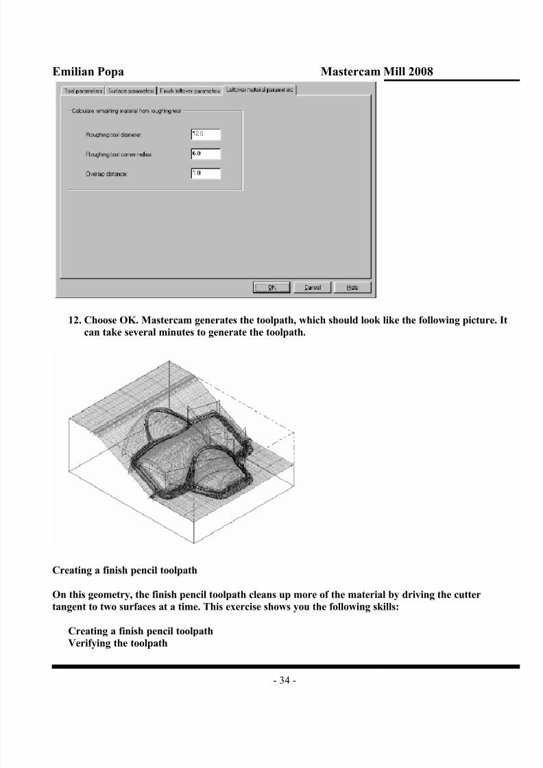
10. Select the Leftover material parameters tab.
11. Enter the values shown on the following dialog box.
8/8/2019 Mill Chapter4
http://slidepdf.com/reader/full/mill-chapter4 34/122
Emilian Popa Mastercam Mill 2008
- 34 -
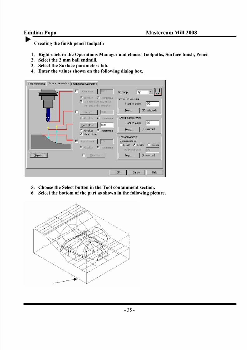
12. Choose OK. Mastercam generates the toolpath, which should look like the following picture. It
can take several minutes to generate the toolpath.
Creating a finish pencil toolpath
On this geometry, the finish pencil toolpath cleans up more of the material by driving the cutter
tangent to two surfaces at a time. This exercise shows you the following skills:
Creating a finish pencil toolpath
Verifying the toolpath
8/8/2019 Mill Chapter4
http://slidepdf.com/reader/full/mill-chapter4 35/122
Emilian Popa Mastercam Mill 2008
- 35 -
Creating the finish pencil toolpath
1. Right-click in the Operations Manager and choose Toolpaths, Surface finish, Pencil
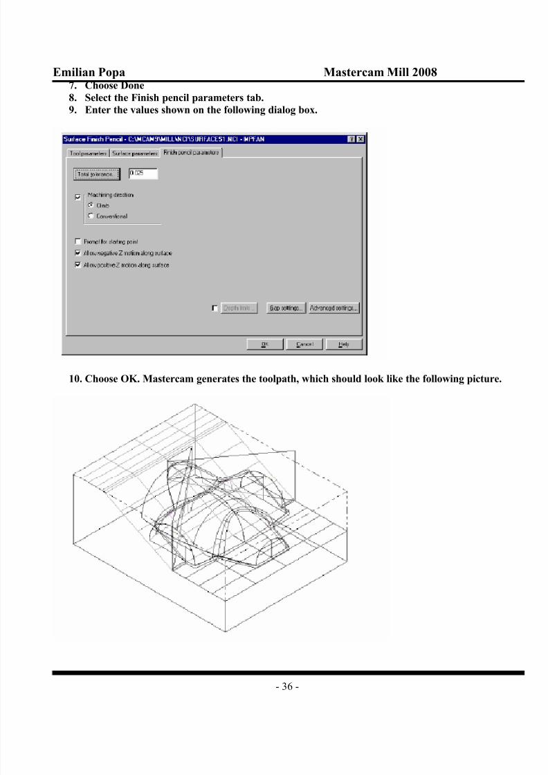
2. Select the 2 mm ball endmill.3. Select the Surface parameters tab.
4. Enter the values shown on the following dialog box.
5. Choose the Select button in the Tool containment section.
6. Select the bottom of the part as shown in the following picture.
8/8/2019 Mill Chapter4
http://slidepdf.com/reader/full/mill-chapter4 36/122
Emilian Popa Mastercam Mill 2008
- 36 -
7. Choose Done
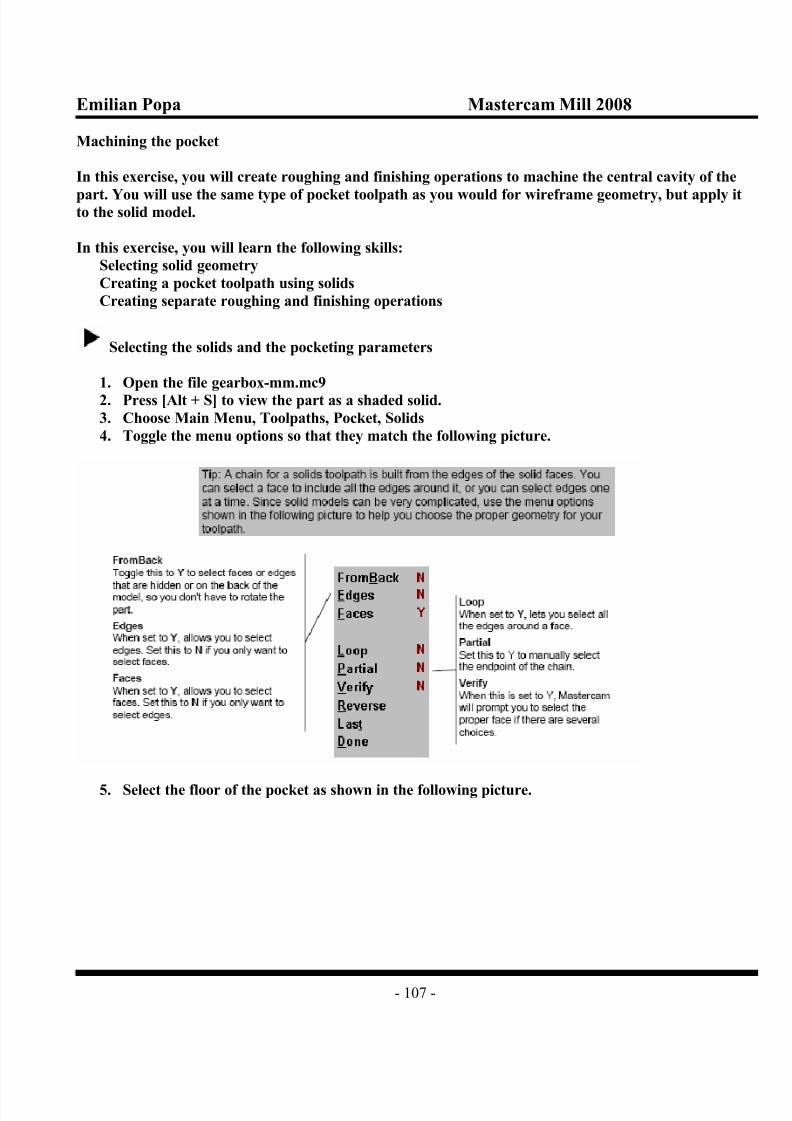
8. Select the Finish pencil parameters tab.
9. Enter the values shown on the following dialog box.
10. Choose OK. Mastercam generates the toolpath, which should look like the following picture.

8/8/2019 Mill Chapter4
http://slidepdf.com/reader/full/mill-chapter4 37/122
Emilian Popa Mastercam Mill 2008
- 37 -
Verifying all the surface toolpaths
You can verify the toolpaths to see the stock removal. Verying all the toolpaths can take a number of minutes, depending on the steed of your computer.
1. If necessary, press [Alt + O] to return to the Operations Manager.
2. Choose Select All, Verify
3. Choose the Configure button on the Verify toolbar.
4. Enter the values shown on the following dialog box and choose OK.
5. Choose the Machine button on the Verify toolbar.
Mastercam runs through the toolpaths and displays the verification results, which should look like the
following picture.

8/8/2019 Mill Chapter4
http://slidepdf.com/reader/full/mill-chapter4 38/122
Emilian Popa Mastercam Mill 2008
- 38 -
6. Choose the Close button on the Verify toolbar to return to the Operations Manager.
7.
Choose OK to close the Operations Manager8. Press [Alt + A] to save the file.
Now that you have experience with creating surface toolpaths, the next two chapters will show you
more types of surface toolpaths and their applications.
Surface Roughing
In the previous chapter, you roughed a part with a rough parallel toolpath. This chapter focuses on
more roughing toolpaths that you can use for surface machining, including:
rough pocket
rough plunge
restmill
high-speed rough pocket
Mastercam also includes rough flowline, contour, and radial toolpaths. These are the same as finish
flowline, contour, and radial toolpaths except that the roughing toolpaths allow multiple Z cuts. Finish
flowline, contour, and radial toolpaths are discussed in the next chapter.
Creating a rough pocket toolpath
Rough pocket toolpaths remove a lot of stock quickly and prepare the part for the finish toolpath.
Another benefit of using a rough pocket toolpath on a part is that you can start the toolpath at a point
off the part and prevent the tool from plunging into the material. A rough pocket toolpath also creates
a series of planar cuts (or constant Z), which is the preferred cutting method for most roughing tools.
You will use the following part.

8/8/2019 Mill Chapter4
http://slidepdf.com/reader/full/mill-chapter4 39/122
Emilian Popa Mastercam Mill 2008
- 39 -
This exercise shows you the following skills:
Creating a rough pocket toolpath
Creating a tool containment boundary
Creating the tool containment boundary
In the previous chapter, you selected geometry that Mastercam used as tool containment boundary.
Since the tool containment boundary has to be wireframe geometry, and this part has only surfaces,
you will create a wireframe boundary that you use for the tool containment.
1. Open the file rough pocket-mm.mc9
2. Choose Main Menu, Create, Curve, All edges
3. Select the flat surface as shown in the following picture.
4. Choose Done, Do it. Mastercam creates lines around the outer border and curves around the
inner border.
Note: You might need to repaint the screen to see the new geometry. Choose the button on the
toolbar.

8/8/2019 Mill Chapter4
http://slidepdf.com/reader/full/mill-chapter4 40/122
Emilian Popa Mastercam Mill 2008
- 40 -
Selecting the surface parameters
1. Choose Main Menu, Toolpaths, Surface
2. Toggle the Drive setting to A. This tells Mastercam that you want to machine all the surface.
3. Toggle Contain to Y.
Your surface selection menu options should match the following picture.
4. Choose Rough, Pocket5. Right-click in the tool display area and select the 10 mm HSS flat endmill from the tool library.
6. Select the Surface parameters tab.
7. Enter the values as shown on the following dialog box.
8. Choose the Select button in the Tool containment section.
9. Select the outer boundary of the part as shown in the following picture.

8/8/2019 Mill Chapter4
http://slidepdf.com/reader/full/mill-chapter4 41/122
Emilian Popa Mastercam Mill 2008
- 41 -
10. Choose Done to return to the Surface parameters dialog box.
Entering the roughing parameters
1. Select the Rough pocket parameters tab.2. Enter the values shown on the following dialog box.
Note: The selections in the previous picture instruct Mastercam to both Plunge outside the tool center
boundary and to create and Entry-helix move. Mastercam will use a helical entry only where it is not
possible to plunge outside the part-in the case of this part, when it machines the hollow on the front of
part.
3. Choose the Entry-helix (or Entry – Ramp) check box and button.
4. Choose the Helix tab
5. Enter the values shown in the following dialog box.

8/8/2019 Mill Chapter4
http://slidepdf.com/reader/full/mill-chapter4 42/122
Emilian Popa Mastercam Mill 2008
- 42 -
6. Choose OK twice.
Mastercam generates the toolpath, which should look like the following picture.
Even though this was a pocket toolpath, it also roughs the outside of the part in addition to the pocket
on the front of the part. Instead of using straight linear cuts like you did in the previous chapter, this
toolpaths uses the Constant Overlap Spiral cutting method which more closely approximates the part
contour for a more effective roughing operation.
7. Save the file in your working folder as rough spiral.mc9

8/8/2019 Mill Chapter4
http://slidepdf.com/reader/full/mill-chapter4 43/122
Emilian Popa Mastercam Mill 2008
- 43 -
Creating a rough plunge toolpath
Rough plunge toolpaths rough a part quickly using a drilling-type motion. Shops that use these
toolpaths often invest in special end cutting tools that have a flat bottom to remove stock quickly but
can move coolant through the center of the tool to remove chips. Plunge roughing is an appropriatetoolpath for deep cavities.
Mastercam gives you two techniques for creating rough plunge toolpaths;
The zigzag method defines a rectangular grid and the tool plunges at intervals along it.
The NCI method lets the tool plunge at intervals along a previously created toolpath.
The NCI option gives you much more control over the plunging actions and will be shown in this
exercise. The wireframe and surface geometry for the part is shown in the following picture.
This exercise shows you the following skills:
Creating a rough plunge toolpath using an NCI file
Using absolute cut depths
Using check surfaces to restrict the toolpath
Creating the pocket toolpath
1. Open the file rough plunge-mm.mc9
2. Choose Main Menu, Toolpaths, Pocket
3. Select the green circle above the part.

8/8/2019 Mill Chapter4
http://slidepdf.com/reader/full/mill-chapter4 44/122
Emilian Popa Mastercam Mill 2008
- 44 -
4. Choose Done
5. Select the 10 mm HSS flat endmill from the tool library
6. Choose the Pocketing parameters tab.
7. Enter the values shown in the following picture.
Note: The depth values are not important, since you won’t actually be cutting the part at these depths.
Instead, Mastercam will project this toolpath onto the part when you create the surface toolpath.
8. Choose the Roughing/Finishing parameters tab.
9. Enter the values shown in the following picture.

8/8/2019 Mill Chapter4
http://slidepdf.com/reader/full/mill-chapter4 45/122
Emilian Popa Mastercam Mill 2008
- 45 -
10. Choose OK. Mastercam creates the toolpath.
11. Choose the green Gview-Top button from the toolbar see the toolpath more clearly. Your
toolpath should look like the following picture.
12.Press [Alt + T] to clear the toolpath from the screen.

8/8/2019 Mill Chapter4
http://slidepdf.com/reader/full/mill-chapter4 46/122
Emilian Popa Mastercam Mill 2008
- 46 -
13. Choose the green Gview-Isometric button from the toolbar to return the screen to isometric
view.
Disabling posting for the pocket toolpath
Mastercam has an option that lets you disable posting for an operation. Since you will not actually be
cutting the pocket toolpath, just the surface toolpath that you will create in the next procedure, you
should disable posting for it so you do accidentally include it in your NC program.
1. Press [Alt + O] to open the Operations Manager.
2. Right-click in the window and choose Options, Posting, Off
The following icon appears in the Operations Manager.
3. Choose OK to close the Operations Manager.
Creating the surface toolpath
1. Choose Surface.2. Toggle the Drive setting to A.
Your options should match the following picture.
Note: Rough Plunge toolpaths don’t use tool containment boundaries, so the Contain setting doesn’t
matter.
3. Choose Rough, Plunge
4. Select the 10 mm HSS flat endmill.
5. Select the Surface parameters tab.
6. Enter the values as shown on the following dialog box.

8/8/2019 Mill Chapter4
http://slidepdf.com/reader/full/mill-chapter4 47/122
Emilian Popa Mastercam Mill 2008
- 47 -
Entering the rough plunge parameters
1. Select the Rough plunge parameters tab.
2. Choose the NCI option for Plunge path.
3. Select the pocket toolpath from the operations list in the Source window. Mastercam will use
the NCI file from this operation to project the toolpath onto the drive surfaces you’ve selected.
4.
Enter the other values as shown on the following dialog box.

8/8/2019 Mill Chapter4
http://slidepdf.com/reader/full/mill-chapter4 48/122
Emilian Popa Mastercam Mill 2008
- 48 -
5. Choose the Cup depths button.
6. Enter the values shown on the following dialog box.
Tip: Setting minimum and maximum cut depths that are well below the bottom of the part as shown
here ensures that the tool goes straight to the bottom of the part without using a pecking motion.
7. Choose OK twice.
Mastercam generates the toolpath, which should look like the following picture.
8. Save the file in your working folder as NCI plunge.mc9

8/8/2019 Mill Chapter4
http://slidepdf.com/reader/full/mill-chapter4 49/122
Emilian Popa Mastercam Mill 2008
- 49 -
Using check surfaces to restrict the toolpath
After inspecting the toolpath, you realize that the tool is plunging on the shallow outer rim of the part.
For a plunge toolpath, this is wasted tool activity. In this procedure, you will edit the surface selectionso that the toolpath avoids these surfaces.
1. Press [Alt + O] to open the Operations Manager.
2. Choose the Parameters icon for the Surface Rough Plunge operation.
3. On the Surface parameters tab, choose the Select button in the Check surface/solid section
4. Choose Add.
5. Choose the two outer surfaces as shown in the following picture.
6. Choose Done twice to return to the Surface parameters, dialog box. Mastercam will now avoid
those two surfaces when creating the toolpath.
7. Enter 1.0 for the Stock to leave in the Check surface/solid section. Your new settings should
match the following picture.

8/8/2019 Mill Chapter4
http://slidepdf.com/reader/full/mill-chapter4 50/122
Emilian Popa Mastercam Mill 2008
- 50 -
Note: Notice that Mastercam automatically updated the number of drive surfaces.
8. Choose OK
9. Choose Regen Path. The new toolpath should look like the following picture. You can see that
all the new plunge points are inside the well of the part.
10. Press [Alt + A] to save the file
Creating a restmill toolpath
Restmilling is the only roughing toolpath that cleans up remaining stock with a roughing, planar
(constant Z) cut motion. Because restmilling uses multiple Z cuts to remove the remaining stock, it is
much more effective than a finish leftover toolpath for operations where the roughing operation has
left a lot of stock to remove. ( A finish leftover toolpath goes directly to the bottom of the remaining
stock, so it is appropriate for finishing operations where a smaller amount of stock remains). The
following pictures show the wireframe and surface geometry for the part.

8/8/2019 Mill Chapter4
http://slidepdf.com/reader/full/mill-chapter4 51/122
Emilian Popa Mastercam Mill 2008
- 51 -
In this exercise, you will learn the following skills:
Using a restmill toolpath to clean up leftover stock
Automatically detecting critical depths
Choosing the surfaces and surface parameters
1. Open the file restmill-mm.mc9
2. Choose Main Menu, Toolpaths, Surface
3. Toggle the Drive setting to A
4. Toggle Contain to Y
Your surface selection menu options should match the following picture.
5. Choose Rough, Pocket
6. Select the 18 mm HSS flat endmill from the tool library.
7. Select the Surface parameters tab.
8. Enter the values as shown on the following dialog box.

8/8/2019 Mill Chapter4
http://slidepdf.com/reader/full/mill-chapter4 52/122
Emilian Popa Mastercam Mill 2008
- 52 -
9. Choose the Select button in the Tool containment section.
10. Choose Chain, Options
11. Select the Plane mask option and choose OK.
12. Select the bottom of the part as shown in the following picture.
13. Choose Done to return to the Surface parameters dialog box.
Entering the pocket parameters
1.
Select the Rough pocket parameters tab.2. Enter the values shown on the following dialog box.

8/8/2019 Mill Chapter4
http://slidepdf.com/reader/full/mill-chapter4 53/122
Emilian Popa Mastercam Mill 2008
- 53 -
3. Choose the Entry-helix (or Entry – ramp) check box and button.
4. Choose the Helix tab.
5. Enter 3 for the Minimum radius.
6. Enter 25 for the Maximum radius . Your values should match the following dialog box.
7. Choose OK.
8. Choose Cut depths
9.
Choose Detect flats in the Incremental depths section Mastercam automatically identifies thetops of the islands and creates cutting passes at those heights. Your other settings should match
the following picture.

8/8/2019 Mill Chapter4
http://slidepdf.com/reader/full/mill-chapter4 54/122
Emilian Popa Mastercam Mill 2008
- 54 -
10. Choose OK twice.
11. Choose OK at the following message.
Mastercam generates the toolpath as shown in the following picture.
Verifying the toolpath
Use the Verify function to see the toolpath more clearly.
1. Press [Alt + O] to open the Operations Manager.
2. Choose Verify
3. Choose the Machine button on the Verify toolbar.
4. When the verification is done, right-click in the graphics window and choose Dynamic spin.
5. Move the mouse to rotate the part as shown in the following picture, so you can see the stock
removal inside the pocket. Click the mouse to anchor the view. You can see the areas where thetool couldn’t reach. The next procedure will how to clean these out with a restmill toolpath.

8/8/2019 Mill Chapter4
http://slidepdf.com/reader/full/mill-chapter4 55/122
Emilian Popa Mastercam Mill 2008
- 55 -
6. Close the Verify toolbar to return to the Operations Manager.
Creating the restmill toolpath
1. Right-click in the Operations Manager window and choose Toolpaths, Surface rough, Restmill
2. Select the 6 mm HSS flat endmill from the tool library.
3. Choose the Surface Parameters tab.
4. Enter the values as shown on the following dialog box.

8/8/2019 Mill Chapter4
http://slidepdf.com/reader/full/mill-chapter4 56/122
Emilian Popa Mastercam Mill 2008
- 56 -
5. Choose the Select button in the Tool containment section.
6. Select the bottom of the part as shown in the following picture.
Note: The plane mask is still in effect from the previous procedure.
7. Choose Done to return to the Surface parameters dialog box/
8. Choose the Restmill parameters tab.
9. Make sure your selections match the following dialog box.

8/8/2019 Mill Chapter4
http://slidepdf.com/reader/full/mill-chapter4 57/122
Emilian Popa Mastercam Mill 2008
- 57 -
10. Choose the Restmaterial parameters tab.
11. Make sure your selections match the following dialog box.
12. Choose OK. Mastercam generates the toolpath as shown in the following picture.

8/8/2019 Mill Chapter4
http://slidepdf.com/reader/full/mill-chapter4 58/122
Emilian Popa Mastercam Mill 2008
- 58 -
Verifying the restmill toolpath
1. Press [Alt + O] to open the Operations Manager.
2. Choose Select All, Verify.
3. Choose the Machine button on the Verify toolbar.
4. When the verificarion is done, right-click in the graphics window and choose Dynamic spin.
5. Move the mouse to rotate the part as shown in the following picture, so you can see the results
achieved by the restmill toolpath. Click the mouse to anchor the view.
6. Close the Verify toolbar to return to the Operations Manager.
7. Choose OK to close the Operations Manager.
8. Save the file in your working folder as restmill rough.mc9
Creating a high speed pocket toolpath
High speed surface machining is often performed using smooth tool motion. Which means that
throughout the entire toolpath, arcs or small line segments are smoothly connected without sharp
corners. Mastercam provides several options for creating the smoothest possible tool motion between
gaps in the toolpath and between depth cuts in the Z axis. In this exercise, you will create a trochoidal
toolpath, in which the tool moves in small loops when it is in full contact with the material to minimize
tool burial and optimize chip load.
In addition, you will create a separate operation that automatically calculates all the plunge points
required by the toolpath and pre-drills them. To make the toolpath even more efficient, Mastercam
can automatically align the plunge points at each cutting depth. The part you will machine is shown in
the following picture.

8/8/2019 Mill Chapter4
http://slidepdf.com/reader/full/mill-chapter4 59/122
Emilian Popa Mastercam Mill 2008
- 59 -
This exercise shows you the following skills:
Creating a high speed rough pocket toolpath
Aligning plunge pointsPre-drilling start holes.
Choosing the surfaces and surface parameters
1. Open the file highspeed rough-mm.mc9
2. If necessary, press [Alt + S] to turn on surface shading.
3. Choose Main Menu, Toolpaths, Surface
4. Toggle the Drive setting to A.
5. Toggle Contain to N.
Your surface selection menu options should match the following picture.
]
6. Choose Rough, Pocket
7. Select the 12 mm HSS flat endmill from the tool library.
8. Select the Surface parameters tab.
9. Enter the values as shown on the following dialog box.

8/8/2019 Mill Chapter4
http://slidepdf.com/reader/full/mill-chapter4 60/122
Emilian Popa Mastercam Mill 2008
- 60 -
Entering the pocket parameters
1. Select the Rough pocket parameters tab.
2. Enter the values shown on the following dialog box.

8/8/2019 Mill Chapter4
http://slidepdf.com/reader/full/mill-chapter4 61/122
Emilian Popa Mastercam Mill 2008
- 61 -
Note: Because the walls of the pocket are tapered, the plunge points for each cutting pass would
normally be shifted slightly at each new depth. Selecting Align plunge entries for start holes means
that Mastercam keeps them lined up, so you can pre-drill just one hole.
3. Choose the High speed button.
4. Select Full material only for the Trochoidal cuts option. This means that the tool will loop only
when it is full contact with the material: when it is partial contact, it will follow the toolpath
normally.
5. Enter the loop dimensions shown in the following dialog box.
6. Choose OK twice. Mastercam generates the toolpath as shown in the following picture.
Because of the island in the middle of the part, a single plunge point for the cutting passes at the lower
depths would result in an unmachinable toolpath. Mastercam recognized the island and automatically
added a second plunge point. However, it still aligned the plunge points in each half of the pocket,
minimizing the start hole drilling.

8/8/2019 Mill Chapter4
http://slidepdf.com/reader/full/mill-chapter4 62/122
Emilian Popa Mastercam Mill 2008
- 62 -
Backplotting the toolpath
Backplot the toolpath to see how Mastercam creates the loops.
1. Press [Alt + O] to return to the Operations Manager.
2. Choose Backplot
3. Switch to Gview-Top
4. Press [S] several times. You will see the toolpath start to develop as shown in the following
picture.
5. Press [Esc] and choose OK to end the backplot6. Switch back to Gview-Isometric.
Creating the start hole operation
1. Choose Backup to return to the Operations Manager.
2. Right-click and choose Toolpaths, Circle paths, Drill start holes.
3. Enter an Additional diameter amount of 3, to provide some clearance for the tool.
4. Choose the Basic option. Your selections should match the following dialog box.

8/8/2019 Mill Chapter4
http://slidepdf.com/reader/full/mill-chapter4 63/122
Emilian Popa Mastercam Mill 2008
- 63 -
5. Choose OK. Mastercam creates the new drilling operation as shown in the following picture.
Even through you created the drilling operation after the pocketing operation. Mastercam
automatically places it first, so the operations are in their proper machining sequence.
Mastercam automatically calculates peck amounts and other parameters. You can edit any of the
drilling parameters by choosing the Parameters icon for the drill operation.
The drill toolpath should look like the following picture.

8/8/2019 Mill Chapter4
http://slidepdf.com/reader/full/mill-chapter4 64/122
Emilian Popa Mastercam Mill 2008
- 64 -
Note: The start hole operation and the pocket operation are not associative with each other. This
means that if you change the pocket toolpath, you need to delete the start hole operation and recreate
it.
6. Choose OK to close the Operations Manager.
7. Save the file in your working folder as highspeed-align.mc9
Now that you’ve see a sampling of Mastercam’s surface roughing capabilities, you’ve ready to usesome surface finishing techniques. The next chapter will show you several examples.
Surface Finishing
This chapter introduces some of the finishing toolpaths you can in surface machining. Finish toolpaths
remove material left behind by previous roughing toolpaths. This chapter shows you examples of the
following finishing toolpaths:
parallel steep
parallel shallow
radialproject
contour
shallow contour
scallop
flowline
Other surface finishing toolpaths include finish parallel, leftover, and pencil toolpaths.

8/8/2019 Mill Chapter4
http://slidepdf.com/reader/full/mill-chapter4 65/122
Emilian Popa Mastercam Mill 2008
- 65 -
Using finish steep and shallow toolpaths
Using finish steep and shallow toolpaths on the following part makes sense because a finish parallel
toolpath would miss material in the steep areas of the part and a finish contour toolpath would miss
material in the shallow areas of the part (see the following pictures). A finish parallel steep toolpath isusually used after a finish parallel toolpath.
In this exercise, you will learn the following skills:
Creating a finish parallel step toolpath
Creating a finish shallow toolpath
Using tangential arcs for gap settings
Creating the parallel steep toolpath
1. Open the file steep-shallow-mm.mc9
2. Choose Main Menu, Toolpaths, Surface3. Toggle the Drive setting to A. This tells Mastercam that you want to machine all the surfaces.
4. Toggle Contain to N. This tells Mastercam that you will not create a tool containment
boundary.
Your surface selection menu options should match the following picture.

8/8/2019 Mill Chapter4
http://slidepdf.com/reader/full/mill-chapter4 66/122
Emilian Popa Mastercam Mill 2008
- 66 -
5. Choose Finish, Par, Steep
6. Right-click in the tool display area and select the 6 mm HSS ball endmill from the tool library.
7. Select the Surface parameters tab.
8. Enter the values as shown on the following dialog box.
9. Select the Finish parallel steep parameters tab.
10. Enter the values shown on the following dialog box.

8/8/2019 Mill Chapter4
http://slidepdf.com/reader/full/mill-chapter4 67/122
Emilian Popa Mastercam Mill 2008
- 67 -
11. Choose Gap settings.
12. Enter the values shown in the dialog box at right.

8/8/2019 Mill Chapter4
http://slidepdf.com/reader/full/mill-chapter4 68/122
Emilian Popa Mastercam Mill 2008
- 68 -
13. Choose OK twice.
Tip: Tangential arcs are useful in steep and shallow toolpaths where you cut a previously finished
surface. They allow the system to blend the entry and exit moves for each cut.
14. Mastercam detects some corners in the part and displays the following message. (The sharp
corner it detects is the ridge along the top of the part). Since this doesn’t affect the toolpath,
choose the Do not show this warning again check box and choose Yes.
Mastercam generates the toolpath on the steep areas of the part between 50 and 90 degrees. It should
look like the following picture.
Creating the finish shallow toolpath
1. Press [Alt + T] to clear the parallel steep toolpath from the screen.

8/8/2019 Mill Chapter4
http://slidepdf.com/reader/full/mill-chapter4 69/122
Emilian Popa Mastercam Mill 2008
- 69 -
2. Choose Finish, Shallow
3. Select the 6 mm HSS ball endmill again.
4. Select the Surface parameters tab.
5. Enter the values as shown on the following dialog box.
6. Select the Finish shallow parameters tab.
7. Enter the values shown on the following dialog box.

8/8/2019 Mill Chapter4
http://slidepdf.com/reader/full/mill-chapter4 70/122
Emilian Popa Mastercam Mill 2008
- 70 -
8. Choose Gap settings
9. Enter the values shown in the dialog box at right.
10. Choose OK twice.
Mastercam generates the toolpath on the shallow areas of the part, between 0 and 10 degrees. It should
look like the following picture.

8/8/2019 Mill Chapter4
http://slidepdf.com/reader/full/mill-chapter4 71/122
Emilian Popa Mastercam Mill 2008
- 71 -
11. Save the file in your working folder as steepandshallow.mc9
Creating a finish radial toolpath
Finish radial toolpaths can be the most efficient toolpaths for rounded parts. In this example, the toolzigzags from the center point to the outer edge of the part. The wireframe and surface geometry for
the part is shown in the following pictures.
This exercise shows you the following skill:
Creating a finish radial toolpath.
Creating the finish radial toolpath
1. Open the file radial-mm.mc9
2. Choose Main Menu, Toolpaths, Surface
3. Toggle Drive to A
4. Toggle Contain to N
Your surface selection menu options should match the following picture.
5. Choose Finish, Radial.
6. Right-click in the tool display area and select the 6 mm HSS ball endmill from the tool library.
7. Select the Surface parameters tab.
8. Enter the values as shown on the following dialog box.

8/8/2019 Mill Chapter4
http://slidepdf.com/reader/full/mill-chapter4 72/122
Emilian Popa Mastercam Mill 2008
- 72 -
9. Select the Finish radial parameters tab.
10. Enter the values shown on the following dialog box.
11. Choose OK.
12. You are prompted to select a rotation point. This is the pivot point for the toolpath slices. Since
the center of this part is X0Y0, press [O] to select the origin.

8/8/2019 Mill Chapter4
http://slidepdf.com/reader/full/mill-chapter4 73/122
Emilian Popa Mastercam Mill 2008
- 73 -
Mastercam generates the toolpath as shown in the following picture.
13. Save the file in your working folder as radial finish.mc9
Creating a finish project toolpath
Finish project toolpaths project either geometry or a toolpath from an earlier operation onto surface
that you select. This finish toolpath provides free-from motion with the ability to match the cutting
motions closely to the shape of the part. It also provides the most tool control. Engraving machining
often uses project toolpaths. The part for this exercise is shown in the following picture. The toolpath
will project the word “PROJECT” onto the part below it.
Note: For more sophisticated engraving applications, you can purchase Mastercam Engraving, which
works with Mastercam Mill.
In this exercise, you will learn the following skill:
Creating a finish project toolpath

8/8/2019 Mill Chapter4
http://slidepdf.com/reader/full/mill-chapter4 74/122
Emilian Popa Mastercam Mill 2008
- 74 -
Creating the project toolpath
1. Open the file project-mm.mc9
2.
Choose Main Menu, Toolpaths, Surface3. Toogle the Drive setting to A
4. Toggle Contain to N
Your surface selection menu options should match the following picture.
5. Choose Finish, Project.
6. Select the 1 mm ball endmill from the tool display window.
7. Select the Surface parameters tab.
8. Enter the values as shown on the following dialog box.
9. Select the Finish project parameters tab.
10. Enter the values shown on the following dialog box.

8/8/2019 Mill Chapter4
http://slidepdf.com/reader/full/mill-chapter4 75/122
Emilian Popa Mastercam Mill 2008
- 75 -
Note: If you had previously created other toolpaths, you could select a toolpath to project in the Source
operations list area.
11. Choose OK.
12. Chain each section of the word “PROJECT” beginning with the outside boundary of the “P”.
Continue selecting the chains in the order shown in the following picture.
13. Choose Done. Mastercam generates the toolpath as shown in the following picture.

8/8/2019 Mill Chapter4
http://slidepdf.com/reader/full/mill-chapter4 76/122
Emilian Popa Mastercam Mill 2008
- 76 -
14. Save the file in your working folder as finish project.mc9
Creating a finish contour toolpath
Finish contour works well for the following part because the part includes several steep walls. The
finish contour toolpath allows the tool to step down gradually in the Z axis instead of stepping over in
the X and Y axes. The following pictures show the wireframe and surface geometry for the part you
will use.
In this exercise, you will learn the following skills:
Creating a finish contour toolpath
Automatically detecting flats
Creating the finish contour toolpath
1. Open the file finish contour-mm.mc9
2. Choose Main Menu, Toolpaths, Surface
3. Toggle the Drive setting to A.
4. Toggle Contain to N

8/8/2019 Mill Chapter4
http://slidepdf.com/reader/full/mill-chapter4 77/122
Emilian Popa Mastercam Mill 2008
- 77 -
Your surface selection menu options should match the following picture .
5. Choose Finish, Contour.
6. Right-click in the tool display area and select the 16 mm HSS bullnose endmill with 3 mm
radius from the library.
7. Select the Surface parameters tab.
8. Enter the values as shown on the following dialog box.
9. Select the Finish contour parameters tab.
10. Enter the values shown on the following dialog box.

8/8/2019 Mill Chapter4
http://slidepdf.com/reader/full/mill-chapter4 78/122
Emilian Popa Mastercam Mill 2008
- 78 -
Note: The ramp length determines the size of the ramp between the constant Z depth cuts. This
provides smooth motion between depth cuts, allowing for higher feed rates.
11. Choose Cut depts.
12. Choose Detect flats in the Incremental section, Mastercam automatically detects the flats in the
following picture. When it creates the toolpath, it will create a cutting pass at this depth.
If you click on the list of depths, you can see the depth of the flats that it detected.

8/8/2019 Mill Chapter4
http://slidepdf.com/reader/full/mill-chapter4 79/122
Emilian Popa Mastercam Mill 2008
- 79 -
13. Make sure your other selections match the following dialog box.
14. Choose OK.
15. Choose Gap settings.
16. Enter the values shown on the following dialog box.

8/8/2019 Mill Chapter4
http://slidepdf.com/reader/full/mill-chapter4 80/122
Emilian Popa Mastercam Mill 2008
- 80 -
17. Choose OK
18. Choose Advanced settings
19. Enter the values shown on the following dialog box.
20. Choose OK twice. Mastercam generates the toolpath as shown in the following picture.
The following closeup shows the constant Z moves in greater detail.

8/8/2019 Mill Chapter4
http://slidepdf.com/reader/full/mill-chapter4 81/122
Emilian Popa Mastercam Mill 2008
- 81 -
21. Save the part in your working folder as finish contour1.mc9
Creating a contour shallow toolpath
The finish contour toolpath that you created in the previous exercise has an option that gives you more
control of the tool motion in shallow areas of a part. You can use this toolpath to reduce or increase the
number of cuts in these areas. The cuts added to the shallow area can be partial or complete. A partial
cut would cause tool motion to be added in only the shallow areas while a complete cut would cause
tool motion to be added in shallow areas and possibly some steeper areas. The following pictures showthe wireframe and surface geometry for the part you will use.
In this exercise, you will learn the following skill:
Optimizing a finish contour toolpath for a shallow part.
Creating the contour shallow toolpath

8/8/2019 Mill Chapter4
http://slidepdf.com/reader/full/mill-chapter4 82/122
Emilian Popa Mastercam Mill 2008
- 82 -
1. Open the file add cuts-mm.mc9
2. Choose Main Menu, Toolpaths, Surface
3. Toggle the Drive setting to A.
4. Toggle Contain to N
Your surface selection menu options should match the following picture.
5. Choose Finish, Contour6. Right-click in the tool display area and select the 18 mm HSS flat endmill from the tool library.
7. Select the Surface parameters tab.
8. Enter the values as shown on the following dialog box.
9. Select the Finish contour parameters tab.
10. Enter the values shown on the following dialog box.

8/8/2019 Mill Chapter4
http://slidepdf.com/reader/full/mill-chapter4 83/122
Emilian Popa Mastercam Mill 2008
- 83 -
11. Choose the Shallow check box and button.
12. Enter the values shown in the following dialog box.
13. Choose OK twice. Mastercam generates the toolpath as shown in the following picture.

8/8/2019 Mill Chapter4
http://slidepdf.com/reader/full/mill-chapter4 84/122
Emilian Popa Mastercam Mill 2008
- 84 -
14. Save the file in your working folder as finish contour shallow.mc9
Creating a finish scallop toolpath
For the part in this exercise, finish scallop creates a consistent scallop height over the whole part
regardless of whether the surface becomes steep or shallow. Mastercam creates the consistent scallop
height without having to double the step size in the steep areas. The following pictures show the
wireframe and surface geometry for the part you will use.
For this exercise, you will learn the following skills:
Creating a finish scallop toolpath
Using the collapse resolution to fine-tune the toolpath
Creating the finish scallop toolpath
1. Open the file scallop-mm.mc9

8/8/2019 Mill Chapter4
http://slidepdf.com/reader/full/mill-chapter4 85/122
Emilian Popa Mastercam Mill 2008
- 85 -
2. Choose Main Menu, Toolpaths, Surface
3. Toggle the Drive setting to A
4. Toggle Contain to N
Your surface selection menu options should match the following picture.
5. Choose Finish, Scallop.
6. Right-click in the tool display area and select the 6 mm HSS ball endmil from the tool library.
7. Select the Surface parameters tab.8. Enter the values as shown on the following dialog box.
9. Select the Finish scallop parameters tab.10. Enter the values shown on the following dialog box.

8/8/2019 Mill Chapter4
http://slidepdf.com/reader/full/mill-chapter4 86/122
Emilian Popa Mastercam Mill 2008
- 86 -
11. Choose Collapse.
12. Enter the values shown in the following dialog box.
Tip: The collapse resolution defines how smoothly the collapse zones of the 3D collapse toolpath are
created. The system uses the stepover percentage to create a “mesh” over the surfaces that determines
where the toolpath is placed. A smaller collapse resolution creates a tighter mesh and a more accuratetoolpath, but it also takes longer to generate and makes a longer NC program.
13. Choose OK.
14. Choose Gap settings.

8/8/2019 Mill Chapter4
http://slidepdf.com/reader/full/mill-chapter4 87/122
Emilian Popa Mastercam Mill 2008
- 87 -
15. Enter the values shown in the dialog box at right.
16. Choose OK twice. Mastercam generates the toolpath as shown in the following picture.
17. Save the part in your working folder as finish scallop.mc9

8/8/2019 Mill Chapter4
http://slidepdf.com/reader/full/mill-chapter4 88/122
Emilian Popa Mastercam Mill 2008
- 88 -
Creating a finish flowline toolpath
Finish flowline toolpaths follow the shape and direction of the surfaces and create a smooth and
flowing toolpath motion. A finish parallel toolpath machines the part at a set angle and does not flow
with the surfaces, resulting in a lot of air cutting. The following pictures show the wireframe andsurface geometry for the part you will use.
In this exercise, you will learn the following skill:
Creating a finish flowline toolpath
Creating the flowline toolpath
1. Open the file flowline-mm.mc9
2. Choose Main Menu, Toolpaths, Surface
3. Toggle the Drive setting to A.
4. Toggle Contain to N.
Your surface selection menu options should match the following picture.
5. Choose Finish, Flowline.

8/8/2019 Mill Chapter4
http://slidepdf.com/reader/full/mill-chapter4 89/122
Emilian Popa Mastercam Mill 2008
- 89 -
6. Right-click in the tool display area and select the 5 mm HSS ball endmill from the tool library.
7. Select the Surface parameters tab.
8. Enter the values as shown on the following dialog box.
9. Select the Finish flowline parameters tab.
10. Enter the values shown on the following dialog box.

8/8/2019 Mill Chapter4
http://slidepdf.com/reader/full/mill-chapter4 90/122
Emilian Popa Mastercam Mill 2008
- 90 -
11. Choose OK
12. You will return to the graphics window, with the Flowline menu displayed. Use the options on
the menu to orient the cutting motion. Toggle the Cut dir setting so that the flow lines and
starting arrows look like the following picture.
13. Choose Done. Mastercam generates the toolpath as shown in the following picture.

8/8/2019 Mill Chapter4
http://slidepdf.com/reader/full/mill-chapter4 91/122
Emilian Popa Mastercam Mill 2008
- 91 -
14. Save the file in your working folder as finish flowline.mc9
In this chapter and the previous chapters, you have seen how Mastercam’s surface machining
toolpaths give you many options for tailoring toolpaths to your part geometry. The next chapter willshow you how Mastercam can use the multiaxis capabilities of your machine tool to produce even more
sophisticated surfacing toolpaths.
Creating Multiaxis Toolpaths
A multiaxis toolpath can be a 3,4, or 5 axis toolpath. With a 3 axis toolpath, you can machine a part on
one side, turn it over, and machine the other side. With a 5-axis toolpath, you can machine a part
without having to turn the part over manually. This chapter introduces you to two different types of
multiaxis toolpaths: a curve 5-axis toolpath and a swarf 5-axis toolpath.
Creating a curve 5-axis toolpath
This exercise shows you how to use 3D curves as an option in a 5-axis toolpath. This toolpath is useful
for a part with curved surfaces because it allows for precise tool tip control. The part in this example, a
blade and root part, has curved surfaces. Unlike the 3-axis contour toolpath, the curve 5-axis toolpath
allows for more precise contact between the tool and the surface material.
The following pictures show wireframe and shaded views of the part.
In this exercise, you will learn the following skills:
Creating a curve 5-axis toolpath with 3-axis outputCreating a curve 5-axis toolpath with 5-axis output
Creating the toolpath with 3-axis output
1. Open curved blade-mm.mc9
2. Choose Main Menu, Toolpaths, Multiaxis, Curve5ax
3. Choose Output Format – 3 Axis
4. Choose the 3D Curves button.

8/8/2019 Mill Chapter4
http://slidepdf.com/reader/full/mill-chapter4 92/122
Emilian Popa Mastercam Mill 2008
- 92 -
5. Choose Single from the menu.
6. Select the top edge of the rib as shown in the following picture.
7. Choose Done to return to the Curve 5-axis dialog box.
8. Choose the Comp to Surfaces button.
9. Select the blate surface as shown in the following picture and choose Done.
10.Make sure your other values match the following dialog box and choose OK.

8/8/2019 Mill Chapter4
http://slidepdf.com/reader/full/mill-chapter4 93/122
Emilian Popa Mastercam Mill 2008
- 93 -
11.You are prompted to select a tool axis surface. Select the blade surface again as shown in step 9
and choose Done.
12. Right-click in the tool display area and choose the 10 mm HSS bullnose endmill with 3 mm
radius form the tool library.
13. Select the Multiaxis parameters tab.
14. Enter the values shown on the following dialog box.
15. Select the Curv5ax Parameters tab.
16. Enter the values shown on the following dialog box.

8/8/2019 Mill Chapter4
http://slidepdf.com/reader/full/mill-chapter4 94/122
Emilian Popa Mastercam Mill 2008
- 94 -
17. Choose OK. Mastercam generates the toolpath, which should look like the following picture.
Adding entry/exit moves
The toolpath for the blade and root part is gouging the material upon entry. You can fix this by adding
parameters for a smooth entry and exit.

8/8/2019 Mill Chapter4
http://slidepdf.com/reader/full/mill-chapter4 95/122
Emilian Popa Mastercam Mill 2008
- 95 -
1. Press [Alt + O] to open the Operations Manager.
2. Choose the Parameters icon for the toolpath.
3. Choose the Multiaxis parameters tab.
4. Choose the Entry/Exit check box and button.5. Enter the values shown on the following dialog box.
6. Choose OK twice.
7. Choose Regen Path. The updated toolpath should look like the following picture.
Note: This picture has been rotated with the Gview-Dynamic function to show the entry/exit moves
more clearly.
Changing the toolpath to 5-axis output

8/8/2019 Mill Chapter4
http://slidepdf.com/reader/full/mill-chapter4 96/122
Emilian Popa Mastercam Mill 2008
- 96 -
Unlike the 3-axis toolpath you just created, the 5-axis toolpath lets the entire surface of the part control
the orientation of the tool. Also, by setting a lead/lag angle for the tool, the tool can lean forward or
backward for more effective cleanout.
1. If necessary, press [Alt + O] to return to the Operations Manager.
2. Choose the Geometry icon for the toolpath.
3. Change the Output Format to 5 Axis and choose OK.
4. Choose the Parameters icon for the toolpath.
5. Choose the Curve5ax Parameters tab
6. Enter a Lead/lag angle of 10

8/8/2019 Mill Chapter4
http://slidepdf.com/reader/full/mill-chapter4 97/122
Emilian Popa Mastercam Mill 2008
- 97 -
7. Choose OK.
8. Choose Regen Path to regenerate the toolpath. It should look like the following picture.
9. Choose OK to close the Operations Manager.
10. Save the file in your working folder as 5ax blade.mc9
Creating a swarf 5-axis toolpath
The swarf 5-axis toolpath uses the side of a tool to remove material from a pocket with tilted walls. The
following pictures show the part in shaded and wireframe views.
In this exercise, you will learn the following skills:
Creating a swarf 5-axis toolpath
Selecting geometry for tool tip control
Using the fan distance to control tool movement around the corners

8/8/2019 Mill Chapter4
http://slidepdf.com/reader/full/mill-chapter4 98/122
Emilian Popa Mastercam Mill 2008
- 98 -
Selecting the surfaces for the toolpath
1. Open the file swarf pocket-mm.mc92. Choose Main Menu, Toolpaths, Multiaxis, Swarf5ax
3. Choose the Surfaces button in the Walls section. The dialog box closes so you can select the
surfaces.
4. Select each of the four walls. Make sure you do not choose the floor.
5. Choose Done.
6. Mastercam prompts you to choose which surface will be machined first. Select at position 1.
7.Mastercam prompts you to identify the lower rail of the surface. Drag the mouse down until the
arrow rests on the lower edge of the surface as shown in the following picture and click.

8/8/2019 Mill Chapter4
http://slidepdf.com/reader/full/mill-chapter4 99/122
Emilian Popa Mastercam Mill 2008
- 99 -
8. Choose Flip from the menu. The arrow should point left.
9. Choose OK. The Swarf 5-axis dialog box reopens. It should look like the following picture.
10. Choose OK.
Selecting the tool and toolpath parameters
1. Right-click in the tool display area and select the 12 mm bullnose endmill with the 1 mm corner
radius from the tool library.
2.
Select the Multiaxis parameters tab.3. Enter the values shown on the following dialog box.

8/8/2019 Mill Chapter4
http://slidepdf.com/reader/full/mill-chapter4 100/122
Emilian Popa Mastercam Mill 2008
- 100 -
4. Choose the Entry/Exit check box and button.
5. Enter the values shown on the following dialog box.
6. Choose OK.
7. Choose the Swarf5ax Parameters tab.
8. Enter the values shown on the following dialog box.
9. Choose OK. Mastercam generates the toolpath, which should look like the following picture.

8/8/2019 Mill Chapter4
http://slidepdf.com/reader/full/mill-chapter4 101/122
Emilian Popa Mastercam Mill 2008
- 101 -
Backplotting the toolpath
To get a better idea of how the side of the tool is cutting the sides of the pocket, backplot the toolpath.
1. Press [Alt + O] toreturn to the Operations Manager.
2. Choose Backplot.
3. Choose Display
4. Choose the Appearance tab.5. Choose the Tool-Shaded option as shown in the following picture.

8/8/2019 Mill Chapter4
http://slidepdf.com/reader/full/mill-chapter4 102/122
Emilian Popa Mastercam Mill 2008
- 102 -
6. Choose OK.
7. Press [R] to preview the toolpath. You should see the tool angle around the pocket like in the
following picture.
Adjusting the tool tip control
In the previous example, the tool tip control parameter was set to the lower rail, which is the line
where the wall meets the floor. However, because the tool is at an angle, the tool will wind up gouging
the floor, as shown in the following picture.
By setting the tool tip control to be the entire floor, Mastercam can prevent this.
1. If necessary, press [Esc] to return to the Operations Manager.
2. Choose the Geometry icon for the toolpath.

8/8/2019 Mill Chapter4
http://slidepdf.com/reader/full/mill-chapter4 103/122
Emilian Popa Mastercam Mill 2008
- 103 -
3. Choose the Surfaces button under Tip Control. The dialog box closes temporarily so you can
choose a surface.
4. Choose the floor of the pocket as shown in the following picture.
5. Choose Done
6. Choose OK when the dialog box displays.
7. Choose Regen Path.8. Choose Backplot
9. Choose the Gview-Side button from the toolbar and press [Page Up] several times to zoom
in on the part, so you can see the tool approach the bottom.
10. Press [S] repeatedly to step through the toolpath. It should look like the following picture. Because
the tool tip control is set to the entire bottom surface, not just the line, the tool tip never gouges the
part.

8/8/2019 Mill Chapter4
http://slidepdf.com/reader/full/mill-chapter4 104/122
Emilian Popa Mastercam Mill 2008
- 104 -
Optimizing the corner transition
In the current toolpath, as the the tool is moving along the walls, it is continually transitioning between
the corner angles:
Mastercam has a fanning capability that you can use to specify a transition area. This way, the tool will
be perpendicular to the floor while machining the walls. The tool only transitions to the corner angle
when it reaches the fanning area.
1. Choose Backup to return to the Operations Manager.
2. Choose the Geometry icon for the toolpath.
3. Select Fanning.
4. Enter a Fan Distance of 12 as shown in the following picture.

8/8/2019 Mill Chapter4
http://slidepdf.com/reader/full/mill-chapter4 105/122
Emilian Popa Mastercam Mill 2008
- 105 -
5. Choose OK
6. Choose Regen Path. As the toolpath machines the walls, it should look like the following
picture.
7. Save the file in your working folder as swarf.mc9
This exercise completes your introduction to creating multiaxis toolpaths in Mastercam. You can learn
about Mastercam’s other types of multiaxis toolpaths – drill, multisurface, flowline, and rotary – in the
online help. The next chapter, which is the final exercise in this tutorial, shows you an example of machining a solid and introduces Mastercam’s feature-based solid drilling function.
Note: You need a Mastercam Solids license to complete the next chapter.
Machining Solids
This chapter introduces you to machining solid geometry. Solids are another type of Mastercam entity,
like surfaces, lines, or arcs. You can either create them in Mastercam or import them from another
program. This chapter does not show you how to create solids; see the Mastercam Solids Tutorial

8/8/2019 Mill Chapter4
http://slidepdf.com/reader/full/mill-chapter4 106/122
Emilian Popa Mastercam Mill 2008
- 106 -
which came with your purchase of Mastercam Solids or the online help for more information about
creating solid geometry.
The part you will machine in this chapter is a gearbox. The following pictures show wireframe and
shaded views of the geometry. You will perform the following operations:pocket out the central cavity
drill and tap the twelve 12 mm blind holes around the top edge
drill the other holes.
You will create a pocket toolpath to machine the cavity and use the Solid Drilling function to drill the
holes.
Note: You need a Mastercam Solids license to complete the exercises in this chapter.
8/8/2019 Mill Chapter4
http://slidepdf.com/reader/full/mill-chapter4 107/122
Emilian Popa Mastercam Mill 2008
- 107 -
Machining the pocket
In this exercise, you will create roughing and finishing operations to machine the central cavity of the
part. You will use the same type of pocket toolpath as you would for wireframe geometry, but apply itto the solid model.
In this exercise, you will learn the following skills:
Selecting solid geometry
Creating a pocket toolpath using solids
Creating separate roughing and finishing operations
Selecting the solids and the pocketing parameters
1. Open the file gearbox-mm.mc9
2. Press [Alt + S] to view the part as a shaded solid.
3. Choose Main Menu, Toolpaths, Pocket, Solids
4. Toggle the menu options so that they match the following picture.
5. Select the floor of the pocket as shown in the following picture.
8/8/2019 Mill Chapter4
http://slidepdf.com/reader/full/mill-chapter4 108/122
Emilian Popa Mastercam Mill 2008
- 108 -
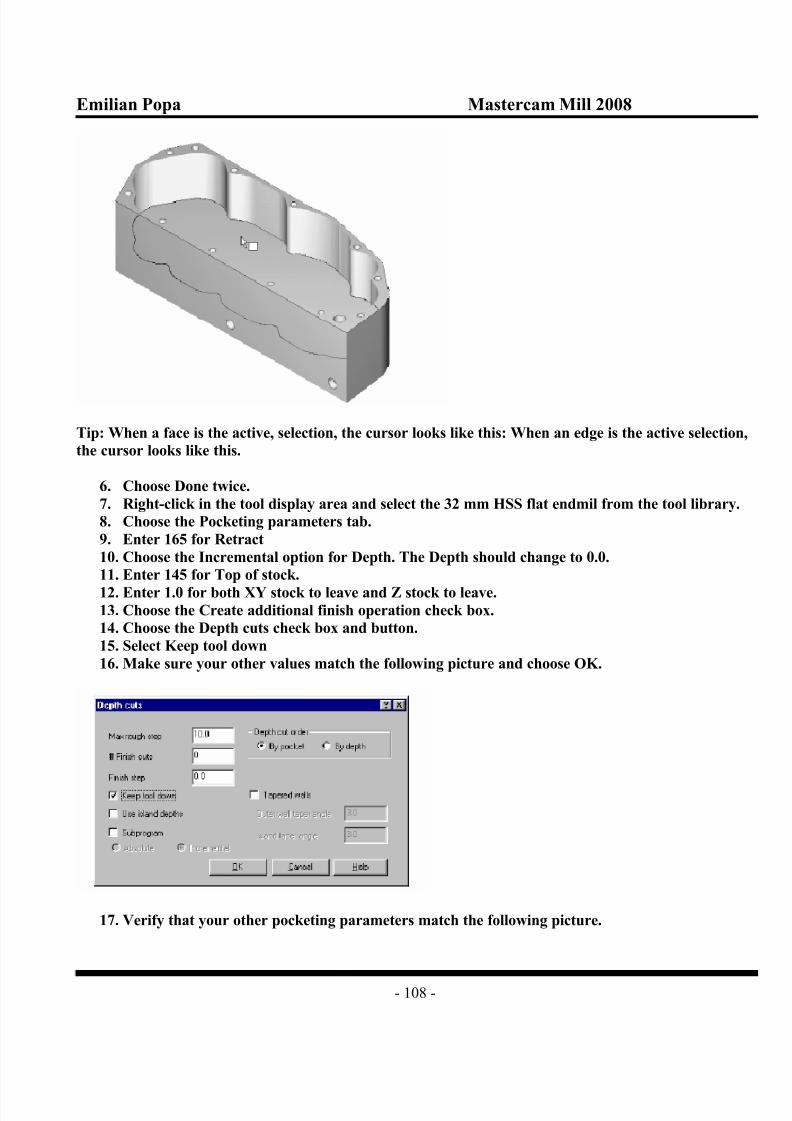
Tip: When a face is the active, selection, the cursor looks like this: When an edge is the active selection,
the cursor looks like this.
6. Choose Done twice.
7. Right-click in the tool display area and select the 32 mm HSS flat endmil from the tool library.
8. Choose the Pocketing parameters tab.
9. Enter 165 for Retract
10. Choose the Incremental option for Depth. The Depth should change to 0.0.
11. Enter 145 for Top of stock.
12. Enter 1.0 for both XY stock to leave and Z stock to leave.13. Choose the Create additional finish operation check box.
14. Choose the Depth cuts check box and button.
15. Select Keep tool down
16. Make sure your other values match the following picture and choose OK.
17. Verify that your other pocketing parameters match the following picture.

8/8/2019 Mill Chapter4
http://slidepdf.com/reader/full/mill-chapter4 109/122
Emilian Popa Mastercam Mill 2008
- 109 -
Selecting roughing and finishing parameters
1. Choose the Roughing/Finishing parameters tab.
2. Choose the Constant Overlap Spiral cutting method
3.
Clear the Finish check box4. Choose the Entry-ramp (or Entry-helix) check box and button.
5. Choose the Ramp tab.
6. Enter the values shown on the following dialog box.

8/8/2019 Mill Chapter4
http://slidepdf.com/reader/full/mill-chapter4 110/122
Emilian Popa Mastercam Mill 2008
- 110 -
7. Choose OK
8. Verify that your Roughing/Finishing parameters match the following picture and choose OK.
Mastercam generates the toolpath.
9. Choose the Repaint button from the toolbar to see the toolpath more clearly. It should look
like the following picture.

8/8/2019 Mill Chapter4
http://slidepdf.com/reader/full/mill-chapter4 111/122
Emilian Popa Mastercam Mill 2008
- 111 -
10.Press [Alt + T] to clear the toolpath display.
Editing the parameters for the finish operation
Since you told Mastercam to create a separate operation for the finish pass, you can edit its
parameters. In this procedure, you will define the lead in/out moves.
1. Press [Alt + O] to open the Operations Manager. You can see two pocket operations.
2. Choose the Parameters icon for the second operation.
3. Choose the Lead in/out check box and button.
4. Enter 10 for Overlap
5. Enter and Entry-Line Length of 0.
6. Enter an Entry – Arc Radius of 50%
7. Copy the values of the Exit section. Your values should match the following picture.
8. Choose OK.9. Verify that your Roughing/Finishing parameters match the following picture.

8/8/2019 Mill Chapter4
http://slidepdf.com/reader/full/mill-chapter4 112/122
Emilian Popa Mastercam Mill 2008
- 112 -
10. Choose the Pocketing parameters tab.
11. Enter 0 for the Z stock to leave.
12. Choose OK
13. Choose Regen Path. Mastercam regenerates the toolpath with the new lead in/out moves for the
finish pass.
Renaming the operations
Since you will be creating many operations to machine this part, you should start naming the
operations and groups to keep them organized.
1. Click on Operation 2 and type in the name Finish as shown in the following picture.

8/8/2019 Mill Chapter4
http://slidepdf.com/reader/full/mill-chapter4 113/122
Emilian Popa Mastercam Mill 2008
- 113 -
2. Press [Enter] to set the name.
3. Click twice on operation 1, type the name Rough and press [Enter]
4. Right-click on Toolpath Group 1 and choose Groups, Rename operation group
5. Enter the name Pocket chamfer. Your operations list should look like the following picture.
6. Choose OK to close the Operations Manager.
7. Choose Main Menu, File, Save and save the file in your working folder as gearbox1.mc9
Drilling the holes
Mastercam’s Solid Drilling function incorporates feature-recognition technology to automatically findall the holes in your solids and create complete drilling operations for them. It is similar to the Auto
Drilling function that you used in Chapter 8. First, you will drill and tap the 12 mm holes on the top
edge of the part. Then, you will drill the remaining holes which are located on different faces of the
part.
In this exercise, you will learn the following skills:
Using Solid Drilling to create drilling, tapping, chamfering, pre-drilling, and spot drilling
operations
Drilling holes in different views
Drilling and tapping the top holes
The first set of drilling operations will be on the twelve 12 mm holes on the top edge of the part. These
need to be drilled and tapped. You will also create separate operations for spot drilling and
chamfering.
1. Choose Main Menu, Toolpaths, Next menu, Solid drill.
2. Choose the Advanced radio button. Mastercam automatically finds all the arcs in the solid.

8/8/2019 Mill Chapter4
http://slidepdf.com/reader/full/mill-chapter4 114/122
Emilian Popa Mastercam Mill 2008
- 114 -
3. You can see that the 12 mm holes are the smallest ones in the list. To quickly screen out the
other holes, enter 12 in the Maximum diameter field and press [Enter]. Your dialog box should
look like the following picture.
4. Choose the Tool Parameters tab.
5. Select a Finish tool type of Tap RH Fine.
6. Select Generate spot drilling operation.
7. Enter a Default spot drill diameter of 25.
8. Select Make separate operation in the Chamfering with spot drill section.
9. Enter a Chamfer size of 1. You other values should match the following picture.

8/8/2019 Mill Chapter4
http://slidepdf.com/reader/full/mill-chapter4 115/122

8/8/2019 Mill Chapter4
http://slidepdf.com/reader/full/mill-chapter4 116/122
Emilian Popa Mastercam Mill 2008
- 116 -
14. Choose the Pre-drilling tab.
15. Choose Generate pre-drill operations.
16. Enter 6 for Minimum pre-drill diameter.
17. Enter 3 for Pre-drill diameter increment. Your values should match the following dialog box.
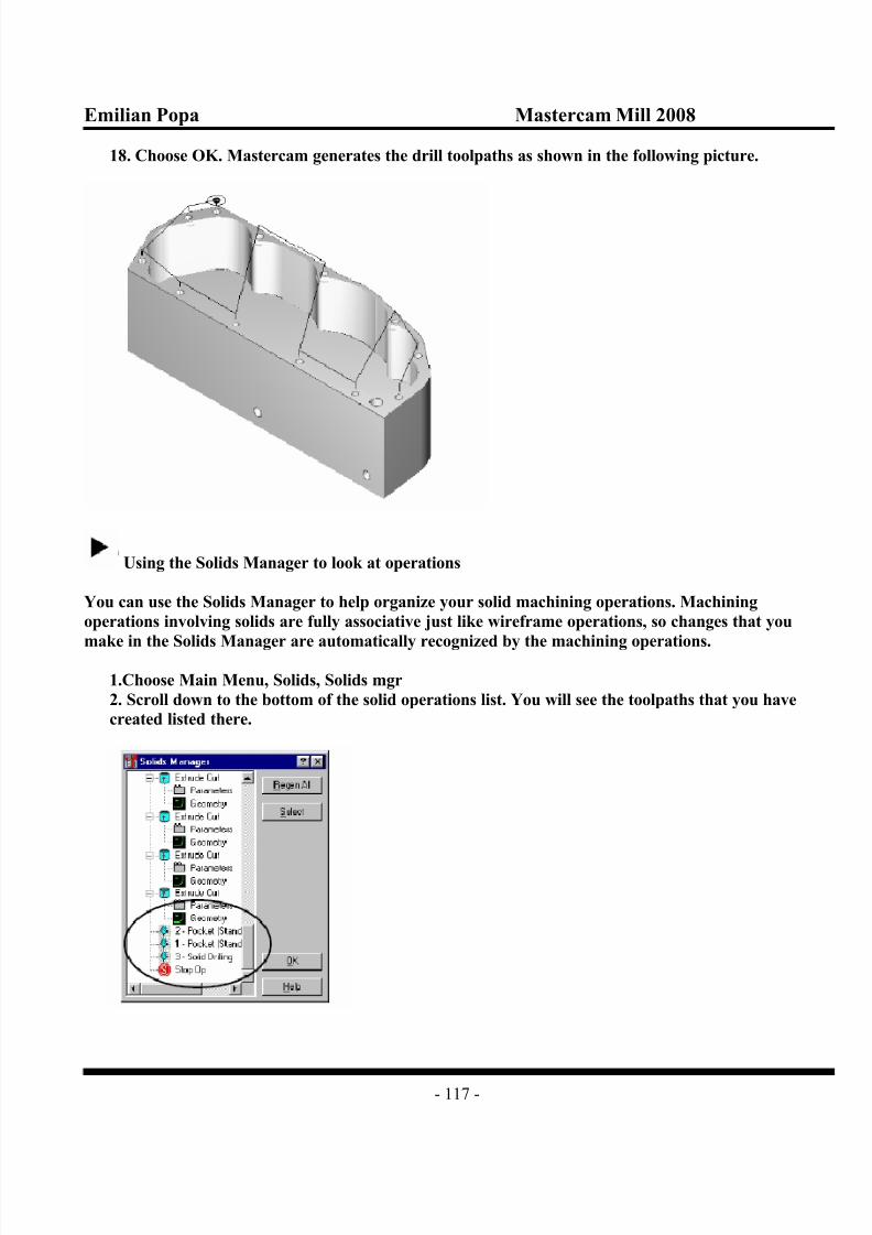
8/8/2019 Mill Chapter4
http://slidepdf.com/reader/full/mill-chapter4 117/122

8/8/2019 Mill Chapter4
http://slidepdf.com/reader/full/mill-chapter4 118/122
Emilian Popa Mastercam Mill 2008
- 118 -
3.Right-click in the window and choose Operations Manager from the menu.
4. Press [E] to collapse the list of operations so you can see them more clearly. It should look like
the following picture.
Tip: Press [E] several more times to collapse and expand the operations list one level at a time.
Drilling the remaining holes
You will use the Solid Drilling function again to create drilling operations for the remaining holes.
Solid Drilling automatically recognizes that the remaining holes are different sizes and are located on
different faces of the part, and so need to be drilled from different angles.
1.Right-click in the Operations Manager and choose Toolpaths, Solids, Drilling.
2. Choose Advanced. Mastercam reads all the arcs in the solid.
Mastercam lists a number of arcs that you do not want to include in this operation, so you will filter
them out by their diameter.
3.Type in a Minimum diameter of 13. The holes smaller than this were drilled and tapped in the
previous procedure, so you don’t want to include them here.
4. Type in a Maximum diameter of 20 and press [Enter]. The arcs larger than this are in the
contour of the pocket, not drilling holes, so you don’t want to include them either.
Your selections should match the following picture.

8/8/2019 Mill Chapter4
http://slidepdf.com/reader/full/mill-chapter4 119/122
Emilian Popa Mastercam Mill 2008
- 119 -
5. Choose the Tool Parameters tab.
6. Select Drill for Finish tool type.
7. Select Generate spot drill operation. Your other values should match the following dialog box.

8/8/2019 Mill Chapter4
http://slidepdf.com/reader/full/mill-chapter4 120/122
Emilian Popa Mastercam Mill 2008
- 120 -
8. Choose the Depths, Group and Library tab.
9. Enter the name Drill same holes in the Drill group and type field.
10. Choose Sort by view.
11. Select the Tip comp check box. Your values should match the following picture.
12. Choose OK.
13. Choose No if you are prompted to sort the other operations. Mastercam generates the drill
toolpaths and shows you the new operations as shown in the following picture.

8/8/2019 Mill Chapter4
http://slidepdf.com/reader/full/mill-chapter4 121/122
Emilian Popa Mastercam Mill 2008
- 121 -
14. Choose OK to close the Operations Manager.
15. Press [Alt + A] to save the file.

8/8/2019 Mill Chapter4
http://slidepdf.com/reader/full/mill-chapter4 122/122