mill creek / green river subregional … river subregional planning area (mc/gr) were identified and...
TRANSCRIPT
CSI PROJECT
MILL CREEK / GREEN RIVER SUBREGIONAL PLANNING AREA
FINAL TASK 250 SUPPLEMENT REPORT WORKING ALTERNATIVE 3A
SOOS PLANNING ZONE
MAY 2002
In Association with
Herrera Environmental Consultants, Inc.


Final Task 250 Supplement—Soos Planning Zone
CONTENTS
Introduction.............................................................................................................................. 1 Cost Estimate Methodology................................................................................................. 2
County Costing Methodology........................................................................................ 12 District Costing Methodology........................................................................................ 12
Working Alternative 3A(1-4) Projects................................................................................... 13 Pump Station H and Conveyance to Pump Station D or Point E ...................................... 14
Project Impacts............................................................................................................... 21 Permit Requirements...................................................................................................... 21 Easement and Property Acquisition............................................................................... 21 Operation and Maintenance ........................................................................................... 21 Design Issues and Constraints ....................................................................................... 23 Construction Cost Estimate............................................................................................ 23
Pump Station F (Lift Station 15B) and Conveyance to Point E (Lift Station 11). ............ 23 Project Impacts............................................................................................................... 24 Permit Requirements...................................................................................................... 28 Easement and Property Acquisition............................................................................... 28 Operation and Maintenance ........................................................................................... 29 Design Issues and Constraints ....................................................................................... 29 Construction Cost Estimate............................................................................................ 29
Conveyance from Point E/Lift Station 11 to Pump Station D - SR18 Interceptor ............ 30 Project Impacts............................................................................................................... 30 Permit Requirements...................................................................................................... 31 Easement and Property Acquisition............................................................................... 31 Operation and Maintenance ........................................................................................... 32 Design Issues and Constraints ....................................................................................... 32 Construction Cost Estimate............................................................................................ 32
Pump Station B and Conveyance to Pump Station D........................................................ 33 Project Impacts............................................................................................................... 33 Permit Requirements...................................................................................................... 34 Easement and Property Requirements ........................................................................... 34 Operation and Maintenance ........................................................................................... 34 Design Issues and Constraints ....................................................................................... 37 Construction Cost Estimate............................................................................................ 37
Pump Station D and Conveyance to Point A..................................................................... 37 Project Impacts............................................................................................................... 44 Permit Requirements...................................................................................................... 45 Easement and Property Acquisition............................................................................... 45 Operation and Maintenance ........................................................................................... 46 Design Issues and Constraints ....................................................................................... 46 Construction Cost Estimate............................................................................................ 46
Timing................................................................................................................................ 49
Appendix A Cost Tables Appendix B Construction Cost Estimates wp4 00-01033-000 mill ck green rvr 250 supp report soos alt 3a.doc
May 10, 2002 Page i

Final Task 250 Supplement—Soos Planning Zone
TABLES
Table 250S-1. Cost Summary for Soos Working Alternative 3, 3A(1-4). ......................... 11 Table 250S-2. Working Alternative Ownership/Responsibility......................................... 13 Table 250S-3. Existing Conditions - Pump Station H and Conveyance to Pump Station
D or Point E. ............................................................................................... 22 Table 250S-4. Estimated Construction Cost - Pump Station H and Conveyance to Pump
Station D or Point E. ................................................................................... 24 Table 250S-5. Existing Conditions - Pump Station F (Lift Station 15B) and
Conveyance to Point E (Lift Station 11)..................................................... 28 Table 250S-6. Estimated Construction Cost - Pump Station F (Lift Station 15B) and
Conveyance to Point E (Lift Station 11)..................................................... 29 Table 250S-7. Existing Conditions - Conveyance from Point E/Lift Station 11 to Pump
Station D - SR18 Interceptor....................................................................... 31 Table 250S-8. Estimated Construction Cost - Conveyance from Point E/Lift Station 11
to Pump Station D - SR18 Interceptor. ....................................................... 32 Table 250S-9. Existing Conditions - Pump Station B and Conveyance to Pump Station
D.................................................................................................................. 34 Table 250S-10. Estimated Construction Cost - Pump Station B and Conveyance to Pump
Station D. .................................................................................................... 37 Table 250S-11. Existing Conditions - Pump Station D and Conveyance to Point A........... 45 Table 250S-12. Estimated Construction Cost-Pump Station D and Conveyance to
Point A. ....................................................................................................... 46
FIGURES
Figure 250S-1. Kent, Auburn, and Soos Planning Zone........................................................ 3 Figure 250S-2. Working Alternative 3 for Soos Planning Zone. .......................................... 5 Figure 250S-3. Working Alternative 3A for Soos Planning Zone......................................... 7 Figure 250S-3A. Working Alternative 3A (Detailed View)..................................................... 9 Figure 250S-4. Pump Station H and Conveyance to Pump Station D or Point E................ 15 Figure 250S-5. Pump Station F (Lift Station 15B) and Conveyance to Point E (Lift
Station 11)................................................................................................... 25 Figure 250S-6. Pump Station B and Conveyance to Pump Station D. ................................ 35 Figure 250S-7. Pump Station B - Area of Interest............................................................... 39 Figure 250S-8. Pump Station D and Conveyance to Point A.............................................. 41 Figure 250S-9. Pump Station D - Area of Interest............................................................... 47 Figure 250S-10. Approximate Component Timing. .............................................................. 50
GRAPH
Graph 250S-1. Pump Station H Timing (Black Diamond Flow) ....................................... 51
wp4 00-01033-000 mill ck green rvr 250 supp report soos alt 3a.doc
Page ii May 10, 2002

Final Task 250 Supplement—Soos Planning Zone
INTRODUCTION
The King County Conveyance System Improvements Project (CSI) is a comprehensive evaluation of the county conveyance system and an assessment of requirements to transport flows projected to the year 2050. General alternatives for additional capacity in the Mill Creek/Green River Subregional Planning Area (MC/GR) were identified and subsequently developed into working alternatives. The work progress and results were reported in Task 210 through 250 for the MC/GR. This 250 supplemental report describes additional engineering planning level analysis performed for the Soos planning zone, as described below.
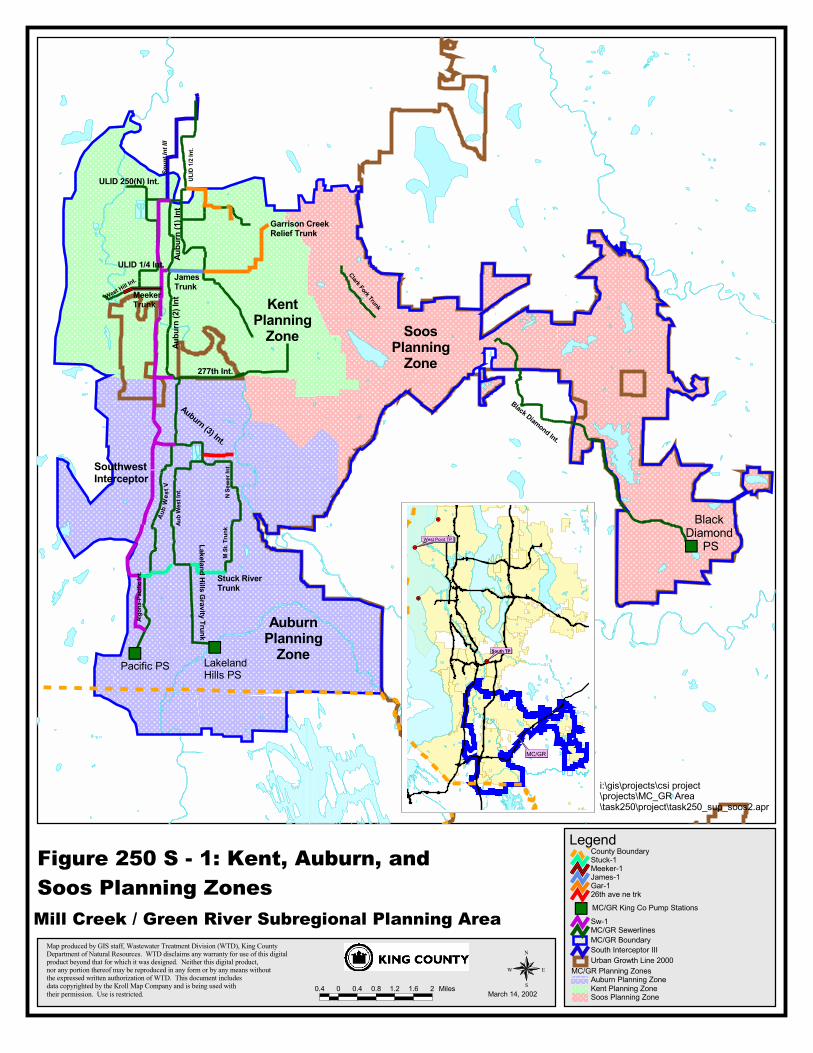
Wastewater flow projections by decade to year 2050 were developed for the MC/GR and presented in the Task 240 report. The flow projections were distributed throughout the MC/GR SPA to specific areas called Flow Projection Areas (FPAs), which generally conform to local agency collection systems. Using the King County hydraulic model, the flow was then routed into the King County conveyance system to assess future lack of capacity. Based on these results, alternatives for providing the required conveyance capacity were developed. For purposes of organizing results and describing alternatives, the MC/GR was divided into three areas or planning zones: Kent, Auburn, and Soos, as shown in Figure 250S-1.
The CSI project has adopted a set of objectives to be considered as the alternatives are evaluated and developed into a working alternative. The objectives to be considered as alternatives were developed included:
• Maximize service by gravity;
• Provide flexibility for adapting to changing growth patterns;
• Maximize long-term facility use;
• Optimize capital and operating cost;
• Provide benefit to regional and local systems;
• Provide certainty to local service providers;
• Integrate projects with other RWSP programs.
The alternatives developed in Task 240 were defined to planning level for comparative evaluation. Initial definition of alternatives included pipe size; general alignment; and recognition of significant features such as roadways, railroads, streams, and wetlands. Comparative evaluation of alternatives was presented in the Task 250 report. Pipe size estimates were used for selecting construction cost unit prices. However, the alternatives were not detailed to the extent that a specific project budget could be identified. The potential impact of infiltration and inflow (I/I) reduction on alternative design and cost was also evaluated and presented in the Task 250 report.
wp4 00-01033-000 mill ck green rvr 250 supp report soos alt 3a.doc
May 10, 2002 Page 1
Final Task 250 Supplement—Soos Planning Zone
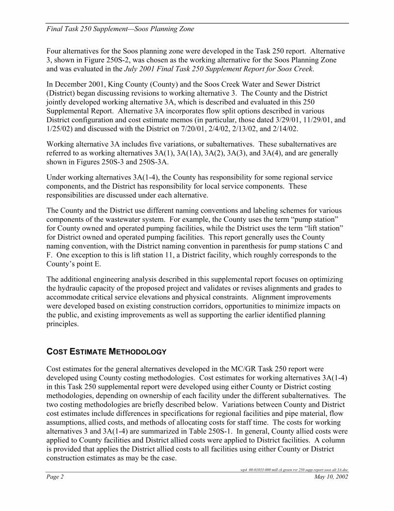
Four alternatives for the Soos planning zone were developed in the Task 250 report. Alternative 3, shown in Figure 250S-2, was chosen as the working alternative for the Soos Planning Zone and was evaluated in the July 2001 Final Task 250 Supplement Report for Soos Creek.
In December 2001, King County (County) and the Soos Creek Water and Sewer District (District) began discussing revisions to working alternative 3. The County and the District jointly developed working alternative 3A, which is described and evaluated in this 250 Supplemental Report. Alternative 3A incorporates flow split options described in various District configuration and cost estimate memos (in particular, those dated 3/29/01, 11/29/01, and 1/25/02) and discussed with the District on 7/20/01, 2/4/02, 2/13/02, and 2/14/02.
Working alternative 3A includes five variations, or subalternatives. These subalternatives are referred to as working alternatives 3A(1), 3A(1A), 3A(2), 3A(3), and 3A(4), and are generally shown in Figures 250S-3 and 250S-3A.
Under working alternatives 3A(1-4), the County has responsibility for some regional service components, and the District has responsibility for local service components. These responsibilities are discussed under each alternative.
The County and the District use different naming conventions and labeling schemes for various components of the wastewater system. For example, the County uses the term “pump station” for County owned and operated pumping facilities, while the District uses the term “lift station” for District owned and operated pumping facilities. This report generally uses the County naming convention, with the District naming convention in parenthesis for pump stations C and F. One exception to this is lift station 11, a District facility, which roughly corresponds to the County’s point E.
The additional engineering analysis described in this supplemental report focuses on optimizing the hydraulic capacity of the proposed project and validates or revises alignments and grades to accommodate critical service elevations and physical constraints. Alignment improvements were developed based on existing construction corridors, opportunities to minimize impacts on the public, and existing improvements as well as supporting the earlier identified planning principles.
COST ESTIMATE METHODOLOGY
Cost estimates for the general alternatives developed in the MC/GR Task 250 report were developed using County costing methodologies. Cost estimates for working alternatives 3A(1-4) in this Task 250 supplemental report were developed using either County or District costing methodologies, depending on ownership of each facility under the different subalternatives. The two costing methodologies are briefly described below. Variations between County and District cost estimates include differences in specifications for regional facilities and pipe material, flow assumptions, allied costs, and methods of allocating costs for staff time. The costs for working alternatives 3 and 3A(1-4) are summarized in Table 250S-1. In general, County allied costs were applied to County facilities and District allied costs were applied to District facilities. A column is provided that applies the District allied costs to all facilities using either County or District construction estimates as may be the case.
wp4 00-01033-000 mill ck green rvr 250 supp report soos alt 3A.doc
Page 2 May 10, 2002
%U %U
%U
Soun
t Int
III
Lakeland Hills Gravity Trunk
ULID
1/2 I
nt.
ULID 250(N) Int.
ULID 1/4 Int.
West Hill Int.
277th Int.
Aub
Wes
t Int
.
Aub
We s
t V
Algo
na-P
acifi
c Int
.
N Se
wer I
nt.
M St
. Tru
nk
Auburn (3) Int.
Clark Fork Trunk
Black Diamond Int.
Pacific PS LakelandHills PS
Black Diamond
PS
Garrison CreekRelief Trunk
JamesTrunk
MeekerTrunk
Stuck RiverTrunk
Map produced by GIS staff, Wastewater Treatment Division (WTD), King CountyDepartment of Natural Resources. WTD disclaims any warranty for use of this digitalproduct beyond that for which it was designed. Neither this digital product,nor any portion thereof may be reproduced in any form or by any means without the expressed written authorization of WTD. This document includesdata copyrighted by the Kroll Map Company and is being used with their permission. Use is restricted. 0.4 0 0.4 0.8 1.2 1.6 2 Miles
N
EW
S
Figure 250 S - 1: Kent, Auburn, and Soos Planning Zones
MC/GR Planning ZonesAuburn Planning ZoneKent Planning ZoneSoos Planning Zone
Urban Growth Line 2000South Interceptor IIIMC/GR BoundaryMC/GR SewerlinesSw-1
%U MC/GR King Co Pump Stations26th ave ne trk Gar-1 James-1 Meeker-1 Stuck-1 County Boundary
March 14, 2002
Legend
#Y
#Y
#Y
#Y#Y
West Point TP
South TP
MC/GR
SouthwestInterceptor
AuburnPlanning
Zone
KentPlanning
Zone SoosPlanning
Zone
Aubu
rn (1
) Int
Aubu
rn (2
) Int
i:\gis\projects\csi project\projects\MC_GR Area\task250\project\task250_sup_soos2.apr
Mill Creek / Green River Subregional Planning Area


Mill Creek / Green River Subregional Planning AreaWorking Alternative 3
Figure 250 S - 2 : Soos Planning Zone Existing Local PS$B
Proposed Regional PS$BReference Point"A
Conveyance Sites
Local PS Eliminated%ILocal PS Continues"G
MC/GR Local PS
MC/GR King Co Pump Stations%UMC/GR SewerlinesStreets - FreewaysMC/GR BoundarySouth Interceptor IIIUrban Growth Line 2000
Legend
Flow Projection AreaABCDFGHCounty Boundary
Proposed SewersProposed GravityProposed ForcemainExisting Local GravityExisting Local Forcemain
May 6, 2002
N
EW
S0.4 0 0.4 0.8 1.2 1.6 2 Miles
Map produced by GIS staff, Wastewater Treatment Division (WTD), King CountyDepartment of Natural Resources. WTD disclaims any warranty for use of this digitalproduct beyond that for which it was designed. Neither this digital product,nor any portion thereof may be reproduced in any form or by any means without the expressed written authorization of WTD. This document includesdata copyrighted by the Kroll Map Company and is being used with their permission. Use is restricted.
%U
"G
"G
"G"G
"G
"G
"G "G
"G
%I
%I
"G
"G
%I
"G "G
"G
"G
%I
"G
%I%I
"G
"G
"G
%I
"G
$B
$B
$B
A
$B
$BA
SE 256th St
124th
Ave
SE
116th
Ave
SE
SE 216th St
Covington-Sawyer Rd
SE Lake Holm Rd
218th
Ave
SE
SE Kent-Kangley Rd
SE Wax
Rd
Lea Hill Rd SE
SE 240th St
216th
Ave
SE
180th
Ave
SE
BlkDiam
ond-Rave
nsdl R
d SE
Lake Sawyer Rd SESE 216th Way
SE Rav
SE 312th St
SE 296th St
SE Wax Rd
196th
Ave
SE
196th Ave SE
SE Lake Holm Rd
Clark Fork TrunkBlack Diamond Int.
Garrison CreekRelief Trunk
Renton Maple Valley Rd
SE 240th St
SE 208th St
140th
Aubu
rn Bla
ck D
iamon
d Rd
Way S
Maple Val- Blk Diam Rd SE
Kent Kangley Rd
numc
law-B
lk Di
amon
d Rd
Kent Black Diamond Rd
SE Wax Rd
SE 272nd St
132n
d Ave
SE
SE 204th Way
SE Kent-Kangley Rd
Roberts Rd
St
192n
d Ave
SE
152n
d Ave
SE
on Rd SE
SR 169
152n
d Ave
SE
Auburn Way S
Maple Val- Blk Diam Rd SE
148th Ave SE
SE 240th St
Auburn Black Diamond Rd
SE Petrovitsky Rd
132n
d Ave
SE
SR 516
Black Diamond PS
Covington-Sawyer Rd
SE 284th St
SE 20
2nd A
ve
E
G
PS H
PS F
PS C
PS D
PS B
i:\gis\projects\csi project\projects\MC_GR area\task250\project\task250_sup_soos2.apr


%U
#Y
#Y
#Y#Y
#Y
#Y #Y
%[
#Y
#Y
%[
%[
#Y #Y
#Y
#Y
%[
#Y
%[#Y
#Y
#Y
#Y
#Y
$T
$T
$T
$T
$T
#S$TSE 256th St
124th
Ave
SE
SE 216th St
Covington-Sawyer Rd
SE Lake Holm Rd
218th
Ave
SE
SE Kent-Kangley R
SE Wax
Rd
a Hill Rd SE
SE 240th St
216th
Ave
SE
180th
Ave
SE
BlkDiam
ond-Rave
nsdR
Lake Sawyer Rd SE
SE 216th Way
SE 312th St
SE 296th St
SE Wax Rd
196th
Ave
SE
196th Ave SE
SE Lake Holm Rd
Clark Fork Trunk
Black Diamond Int.
Creekunk
Renton Maple Valley Rd
SE 240th St
SE 208th St
Aubu
rn Bla
ck D
iamon
d Rd
Maple Val- Blk Diam Rd SE
Kent Kangley Rd
Dam
Kent Black Diamond Rd
SE Wax Rd
SE 272nd St
132n
d Ave
SE
SE 204th Wa
SE Kent-Kangley Rd
Roberts Rd
192n
d Ave
SE
152n
d Ave
SE
SR 169
152n
d Ave
SE
Auburn Wa
Maple Val- Blk Diam Rd SE
148th Ave SE
SE 240th St
Auburn Black Diamond Rd
SE Petrovitsky Rd
132n
d Ave
SE
SR 516
Black DiamondPS
Covington-Sawyer Rd
SE 284th StSE
202n
d Ave
Map produced by GIS staff, Wastewater Treatment Division (WTD), King CountyDepartment of Natural Resources. WTD disclaims any warranty for use of this digitalproduct beyond that for which it was designed. Neither this digital product,nor any portion thereof may be reproduced in any form or by any means without the expressed written authorization of WTD. This document includesdata copyrighted by the Kroll Map Company and is being used with their permission. Use is restricted.
0.4 0 0.4 0.8 1.2 1.6 2 Miles
N
EW
S
May 6, 2002
Figure 250 S - 3 : Soos Planning Zone Mill Creek / Green River Subregional Planning AreaWorking Alternative 3A
Legend
Urban Growth Line 2000South Interceptor IIIMC/GR BoundaryStreets - FreewaysMC/GR Sewerlines
%U MC/GR King Co Pump Stations
Proposed SewersProposed GravityProposed ForcemainExisting Local GravityExisting Local ForcemainPropsed Gravity SewerProposed Gravity Sewer
MC/GR Local PS"G Local PS Continues
%I Local PS Eliminated
Conveyance Sites"A Reference Point
$B Proposed Regional PS
$B Existing Local PS
PS B
PS D
PS C
PS F
PS H
G
E
Flow Projection AreaABCDFGH
i:\gis\projects\csi project\projects\MC_GR area\task250\project\task250_sup_soos2.apr


Map produced by GIS staff, Wastewater Treatment Division (WTD), King CountyDepartment of Natural Resources. WTD disclaims any warranty for use of this digitalproduct beyond that for which it was designed. Neither this digital product,nor any portion thereof may be reproduced in any form or by any means without the expressed written authorization of WTD. This document includesdata copyrighted by the Kroll Map Company and is being used with their permission. Use is restricted.
0.2 0 0.2 0.4 0.6 0.8 1 1.2 1.4 Miles
N
EW
SMay 6, 2002
Figure 250 S - 3A : Soos Planning Zone Mill Creek / Green River Subregional Planning AreaWorking Alternative 3A
%U
#Y
#Y
#Y
#Y #Y
%[
#Y
#Y
%[
%[
#Y #Y
#Y
#Y
%[
#Y
%[
#Y
#Y
#Y
#Y
#Y
$T
$T
$T
$T
$T
#S$TSE 256th St
124th
Ave
SE
SE 216th St
Covington-Sawyer Rd
SE Lake Holm Rd
218th
Ave
SE
SE Kent-Ka
SE Wax
RdSE 240th St
216th
Ave
SE
180th
Ave
SE
BlkDiam
ond
Lake Sawyer Rd SE
SE 216th Way
SE 312th St
SE 296th St
SE Wax Rd
196th
Ave
SE
196th Ave SE
SE Lake Holm Rd
Clark Fork Trunk
Black Diamond Int.
Renton Maple Valley Rd
SE 240th St
E 208th St
Aubu
rn Bla
ck D
iamon
d Rd
Maple Val- Blk Diam Rd SE
Kangley Rd
Kent Black Diamond Rd
SE Wax Rd
SE 272nd St
132n
d Ave
SE
SE 204th Way
SE Kent-Kangley Rd
Roberts Rd
192n
d Ave
SE
152n
d Ave
SE
SR 169
152n
d Ave
SE
Auburn Way S
Maple Val- Blk Diam Rd SE
148th Ave SE
St
Auburn Black Diamond Rd
SE Petrovitsky Rd
132n
d Ave
SE
SR 516
Black D amPS
Covington-Sawyer Rd
SE 284th St
SE 20
2nd A
ve
Quick Facts* Costs being developed are based on both KC & District estimates
* Option exists for District to build KC owned & operated LS 11/SR 18
* Timing dependent on flow to PS D; likely by year 2007
PS C
PS B
PS D
E
PS H
PS F
G
#Y
#Y
#Y
%[
#Y
$T
#S$T
SE Wax
Rd
180th
Ave
SE
1 & 2
4
3
1 & 2
3
4
PS D
E
1 = PS/FM = 3A (1)2 = Gravity tunnel = 3A (2)3 = Gravity = 3A (3)4 = Gravity = 3A (4)
Legend
Urban Growth Line 2000South Interceptor IIIMC/GR BoundaryStreets - FreewaysMC/GR Sewerlines
%U MC/GR King Co Pump Stations
Proposed SewersProposed GravityProposed ForcemainExisting Local GravityExisting Local ForcemainPropsed Gravity SewerProposed Gravity Sewer
MC/GR Local PS"G Local PS Continues
%I Local PS Eliminated
Conveyance Sites"A Reference Point
$B Proposed Regional PS
$B Existing Local PS
Flow Projection AreaABCDFGH
i:\gis\projects\csi project\projects\MC_GR Area\task250\project\task250_sup_soos2.apr


Final Task 250 Supplement—Soos Planning Zone
Table 250S-1. Cost Summary for Soos Working Alternative 3, 3A(1-4).
Summary Working Alternatives 3, 3A(1-4)
Summary
Construction ($)
Total Project a ($)
Total Project b
($)
Working Alternative 3 c County Ownership $78,150,000 $132,654,000 $125,040,000 District Ownership – – –
Total $78,150,000 $132,654,000 $125,040,000 Working Alternative 3A(1) d County Ownership $56,842,000 $ 96,455,000 $ 90,949,000 District Ownership $ 6,689,000 $ 10,702,000 $ 10,702,000
Total $63,531,000 $107,157,000 $101,651,000 Working Alternative 3A(1A) e County Ownership $45,602,000 $ 77,380,000 $ 72,965,000 Lift Station 11 & SR18 Interceptor $11,240,000 $ 17,984,000 $ 17,984,000 District Ownership $ 6,689,000 $ 10,702,000 $ 10,702,000
Total $63,531,000 $106,066,000 $101,651,000 Working Alternative 3A(2) f County Ownership $56,715,000 $ 96,259,000 $ 90,746,000 District Ownership $ 6,689,000 $ 10,702,000 $ 10,702,000
Total $63,404,000 $106,961,000 $101,448,000 Working Alternative 3A(3) g County Ownership $47,023,000 $ 81,645,000 $ 75,239,000 District Ownership $11,197,000 $ 17,912,000 $ 17,912,000
Total $58,220,000 $ 99,557,000 $ 93,151,000 Working Alternative 3A(4) h County Ownership $51,323,000 $ 89,213,000 $ 82,119,000 District Ownership $11,197,000 $ 17,912,000 $ 17,912,000
Total $62,520,000 $107,125,000 $100,031,000 a District allied cost (60%) for District facilities or County 2003 budget model allied cost for County facilities except in Alt
3A(1A) where District allied cost is applied to County construction cost indicating County ownership/District construction for LS 11 and the SR18 Interceptor.
b District allied cost (60%) for all facilities. c All facilities owned by the County/PS H routed to Point E. d PS C and F owned by District/PS B, D, and H owned by County/SR18 and LS11 - owned by County and County
Construction/PS H routed to Point E. e PS C and F owned by District/PS B, D, and H owned by County/SR18 and LS11 - owned by County and District
Construction/PS H routed to Point E. f PS C and F owned by District/PS B, D, H, SR18 owned by County/PS H routed to Point E. g PS C, F, LS11, and SR18 owned by District/PS B, D, and H owned by County/PS H routed to PS D via Power Line. h PS C, F, LS11, and SR18 owned by District/PS B, D, and H owned by County/PS H routed to PS D via 272nd.
Appendix A includes cost summaries for working alternatives 3 and 3A(1-4). Cost summaries in working alternative project discussions include construction costs only. The tables included in Appendix A compare different allied cost applications with each working alternative project. More detailed discussions of working alternative project costs will be included in the final version of this report.
Final predesign studies may determine that the budgeting level estimates of cost for certain components contained herein are over-estimated while others are under-estimated. The estimates
wp4 00-01033-000 mill ck green rvr 250 supp report soos alt 3a.doc
May 10, 2002 Page 11

Final Task 250 Supplement—Soos Planning Zone
presented may be reduced by refinement during design. Estimated construction costs are presented in year 2002 dollars.
COUNTY COSTING METHODOLOGY
Construction cost estimates were prepared for the general alternatives developed in the MC/GR Task 250 report using details presented in King County Conveyance System Improvement Project Conveyance System Cost Estimates Task 250 Final Report dated September 21, 2001. Construction cost estimates are presented in Appendix B. The cost tables presented were based on a fixed average condition for varying pipe diameter and are derived from an extensive County cost model that develops cost for a variety of construction scenarios. The cost model allows site-specific conditions including depth and unit material prices to be factored into a specific unit price for a constructed facility. Pipeline cost has been assumed to include import fill of trenches, relocation of existing utilities, dewatering, and pavement restoration throughout the project length.
Pump station estimates include assumptions for site/civil, electrical/instrumentation, architectural/structural, and mechanical components based on a fixed cost per mgd of flow pumped. The estimates are conservative and will be refined during predesign.
The cost model developed by the County has been refined and released as the CSI cost model Tabula Version 1.0, and is available for download at http://dnr.metrokc.gov/WTD/CSI/planning/htm.
The County’s method for determining total project costs involves a separate budget model that allocates a range of element costs to the construction estimates generated by the County’s Tabula Version 1.0. These project costs involve such factors as engineering costs, contingencies, and permitting, and are based on details from over $1.1 billion dollars of County wastewater projects.
DISTRICT COSTING METHODOLOGY
Costs for District facilities in this report were provided directly by the District, with less detailed information on assumptions and methodologies provided. Generally, District costs are based on unit costs determined from District bid tabs. The District uses a standard 60 percent multiplier for allied costs; 20 percent contingency and 40 percent for other costs. The cost tables in this report do not include unit information such as pump station capacity for District facilities, as the District-supplied costs reflect different capacity and specification assumptions. This information was provided in a Roth Hill memo to the County dated January 25, 2002.
wp4 00-01033-000 mill ck green rvr 250 supp report soos alt 3A.doc
Page 12 May 10, 2002

Final Task 250 Supplement—Soos Planning Zone
WORKING ALTERNATIVE 3A(1-4) PROJECTS
The Soos Planning Zone working alternatives 3A(1-4) include five projects: Pump station H and conveyance to pump station D or point E; pump station F (lift station 15B) and conveyance to point E or lift station 11; conveyance from point E (lift station 11) to pump station D - SR18 Interceptor; pump station B and conveyance to pump station D; and pump station D and conveyance to point A. Pump station C (lift station 10B) is owned by the County in working alternative 3 and by the District in working alternatives 3A(1-4) and is not included as a project in this report. Pump station C (lift station 10B) has no conveyance component required for future flow if existing forcemains are used.
Several differences exist between working alternatives 3 and 3A(1-4). All project components in working alternative 3 were assumed to be County facilities. In working alternatives 3A(1-4), the County owns some components, and the District owns and retains responsibility for some components. The component ownership is shown in Table 250S-2.
Table 250S-2. Working Alternative Ownership/Responsibility.
Alternative
Facility 3 3A(1) 3A(1A) 3A(2) 3A(3) 3A(4)
Pump Station H and Conveyance to Pump Station D or Point E
County County County County County County
Pump Station F (Lift Station 15B) and Conveyance to Point E (Lift Station 11)
County District District District District District
Conveyance from Point E/Lift Station 11 to Pump Station D - SR18 Interceptor
County County County a County District District
Pump Station B and Conveyance to Pump Station D
County County County County County County
Pump Station D and Conveyance to Point A
County County County County County County
a District Builds to County Specifications
Project components and specific differences between the subalternatives are discussed in detail in subsequent sections, in addition to issues and constraints that may impact project implementation. Project components presented are planning level and are subject to further revisions as project implementation proceeds.
Generally, working alternatives 3A(1), 3A(1A), and 3A(2) are all similar to the original working alternative 3. The primary differences between these and the original working alternative 3 involve ownership of pump station C (lift station 10B) and pump station F (lift station 15B), and the design of conveyance from point E to pump station D along SR18 (deep tunnel gravity versus open cut with pump station). Working alternatives 3A(3) and 3A(4) both divert flows from point E, and present two different alignments from pump station H to pump station D.
wp4 00-01033-000 mill ck green rvr 250 supp report soos alt 3a.doc
May 10, 2002 Page 13

Final Task 250 Supplement—Soos Planning Zone
All pump stations are proposed facilities, except for pump station G which currently serves the City of Black Diamond. In some of the working alternatives, lift station 11 would be expanded or would be a new facility.
PUMP STATION H AND CONVEYANCE TO PUMP STATION D OR POINT E
A regional pump station (pump station H), forcemain H, and a gravity sewer (Black Diamond Parallel Interceptor) convey flow to pump station D or point E as shown in Figure 250S-4. Depending on the construction methods (tunnel or open cut) used for the SR18 Interceptor, lift station 11 located near point E may be required. Pump station H operates at about 51 feet of total dynamic head. The conveyance to pump station D includes approximately 1,000 feet of forcemain and 35,000 feet of gravity sewer to point E; or 1,000 feet of forcemain and 35,300 feet or 49,500 feet of gravity sewer to pump station D, depending on the alignment selected.
Three configurations for the gravity sewer portion of conveyance to pump station D or point E have been developed. In working alternatives 3A(1, 1A, and 2) the gravity sewer portion of the conveyance parallels the existing gravity sewer to point E and includes about 35,000 feet of gravity sewer. In working alternatives 3A (3 and 4), the gravity sewer parallels the existing gravity sewer to an overhead power line corridor near SE 284th Street. The gravity sewer either turns west along the power line corridor, or continues to parallel the existing interceptor to SE 272nd Street, where it turns west. The gravity sewer terminates at pump station D in both the power line and SE 272nd Street alignments. The total length for the power line corridor alignment and the SE 272nd Street alignment from pump station H to pump station D is 35,300 feet and 49,500 feet respectively.
The existing Black Diamond Pump station (pump station G) currently conveys flow to the Black Diamond Interceptor, which discharges to lift station 11. In working alternative 3A(1), lift station 11 is a new County pump station and conveys flow to the SR18 Interceptor. In working alternative 3A(1A), lift station 11 is a County facility, possibly constructed by the District, and conveys flow to the SR18 Interceptor. In working alternative 3A(2), lift station 11 is decommissioned and flow is conveyed from point E to pump station D through a microtunneled SR18 Interceptor. In working alternatives 3A(3 and 4), flow from the Black Diamond Parallel Interceptor is re-routed to pump station D and lift station 11 is a District facility converted to low-head service, and conveys flow to the SR18 Interceptor as needed in the future.
Pump station G conveys flow to pump station H and will remain in service to its current service area through the planning period. The combined capacity of pump station G and pump station H would be adequate for the County’s projected flows through year 2050.
The following photographs depict existing conditions along forcemain H and the Black Diamond Parallel Interceptor alignments. The approximate location of each photograph is indicated in Figure 250S-4. A brief description of access concerns for each representative section of the proposed alignment is included.
wp4 00-01033-000 mill ck green rvr 250 supp report soos alt 3A.doc
Page 14 May 10, 2002

%U
#Y
%[
#Y #Y
#Y
#Y
%[
#Y
#Y#Y
#Y
#Y
$T
$T
$T
#S$TSE 256th St
Covington-Sawyer Rd
SE Lake Holm Rd
218th
Ave
SE
SE Kent-Kangley Rd
SE Wax
Rd
SE 240th St
216th
Ave
SE
180th
Ave
SE
BlkDiam
ond-Rave
nsdl R
d SE
Lake Sawyer Rd SE
SE Ravensd
a
SE 296th St
SE Wax Rd
196th
Ave
SE
Black Diamond Int.
SE 240th St
Maple Val- Blk Diam Rd SE
w-Blk
Diam
ond R
d
Kent Black Diamond Rd
SE Wax Rd
SE 272nd St SE Kent-Kangley Rd
Roberts Rd
192n
d Ave
SE
152n
d Ave
SE
SR 169
152n
d Ave
SE
Maple Val- Blk Diam Rd SE
148th Ave SE
Auburn Black Diamond Rd
SR 516
Black Diamond PS
Covington-Sawyer Rd
SE 284th St
SE 20
2nd A
ve
Map produced by GIS staff, Wastewater Treatment Division (WTD), King CountyDepartment of Natural Resources. WTD disclaims any warranty for use of this digitalproduct beyond that for which it was designed. Neither this digital product,nor any portion thereof may be reproduced in any form or by any means without the expressed written authorization of WTD. This document includesdata copyrighted by the Kroll Map Company and is being used with their permission. Use is restricted. 0.4 0 0.4 0.8 1.2 Miles
N
EW
S
Figure 250 S - 4 : Soos Planning Zone
May 6, 2002
i:\gis\projects\csi project\projects\MC_GR area\task250\project\task250_sup_soos2.apr
P9
P6 P5
P4
P3
P1
P2
P7
PS H
PS D
G
Mill Creek / Green River Subregional Planning AreaWorking Alternative Component - PS H and Conveyance to Point Eor Pump Station D
E
PS F
P12 P13
P11
P10
Existing Local PS$BProposed Regional PS$BReference Point"A
Conveyance Sites
MC/GR Local PS
Local PS Eliminated%ILocal PS Continues"G
MC/GR King Co Pump Stations%UMC/GR SewerlinesStreets - FreewaysMC/GR BoundarySouth Interceptor III
Legend
Proposed SewersProposed GravityProposed ForcemainExisting Local GravityExisting Local ForcemainPropsed Gravity SewerProposed Gravity Sewer
Urban Growth Line 2000
Photo Reference Point
P8
P15
P14
Railroad Flow Projection AreaABCDFGH


Final Task 250 Supplement—Soos Planning Zone
P1: Roberts Drive – Rock Creek to Lake Sawyer Road SE
P2: Lake Sawyer Road SE – Roberts Drive to 224th Avenue SE
Vehicular access along Roberts Drive must be maintained. Impacts to Rock Creek should be minimized.
Access to homes, businesses, and roadways must be maintained.
P1 P2
P4: 296th Street – 224th Avenue SE to
216th Avenue SE
P3: 224th Avenue SE – Lake Sawyer Road SE to SE 296th Street
Access to homes, businesses, and roadways must be maintained.
Access to homes, businesses, and roadways must be maintained.
P4
P3
wp4 00-01033-000 mill ck green rvr 250 supp report soos alt 3a.doc
May 10, 2002 Page 17

Final Task 250 Supplement—Soos Planning Zone
P5: Covington-Sawyer Road – 216th Avenue SE to 202nd Avenue SE
P6: 202nd Avenue SE – Covington-Sawyer Road to SE 284th Street:
Access to roadways and homes must be maintained.
Access to roadways and homes must be maintained.
P6
P5
P8: 192nd Place SE – 193rd Place SE to SE
272nd Street (SE 272nd Street Alignment):
P7: 193rd Avenue SE – SE 284th Street to 192nd Place SE:
Access to roadways and homes must be maintained.
Access to roadways and homes must be maintained.
P8
P7
wp4 00-01033-000 mill ck green rvr 250 supp report soos alt 3A.doc
Page 18 May 10, 2002

Final Task 250 Supplement—Soos Planning Zone
P10: SE Wax Road – SR 516 to
Covington-Sawyer Road (SE 272nd Street Alignment):
P9: SE 272nd Street – 192nd Avenue SE to SE Wax Road (SE 272nd Street Alignment):
Access to roadways, homes, and businesses must be maintained.
Access to roadways, homes, and businesses must be maintained.
P1Roan
Acmu
wp4
Ma
P9
P9
1: Covington-Sawyer Rd. – SE Wax ad to Gravel Quarry (SE 272nd Street d Power Line Alignment):
P1PSAl
cess to roadways, homes, and businesses st be maintained.
Acma
P11
00-01033-000 mill ck green rvr 250 supp report soos alt 3a.doc
y 10, 2002
P10
P10
2: Gravel Quarry – Gravel Quarry to D (SE 272nd Street and Power Line
ignment):
cess to the gravel quarry must be intained.
12
Page 19
Final Task 250 Supplement—Soos Planning Zone
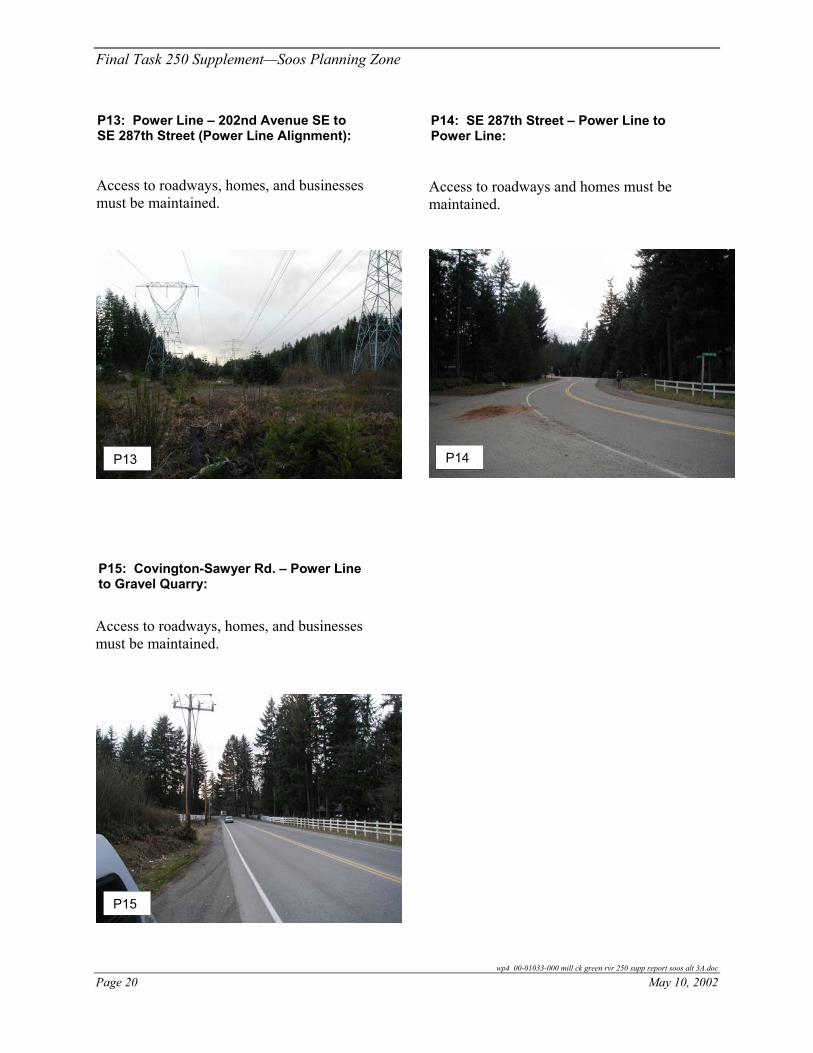
P13: Power Line – 202nd Avenue SE to SE 287th Street (Power Line Alignment):
P14: SE 287th Street – Power Line to Power Line:
Access to roadways, homes, and businesses must be maintained.
Access to roadways and homes must be maintained.
P14
P13
P15: Covington-Sawyer Rd. – Power Line to Gravel Quarry:
Access to roadways, homes, and businesses must be maintained.
P15
wp4 00-01033-000 mill ck green rvr 250 supp report soos alt 3A.doc
Page 20 May 10, 2002

Final Task 250 Supplement—Soos Planning Zone
PROJECT IMPACTS
Typical temporary construction related impacts may include increased noise, dust and construction vehicle traffic. Temporary partial road closures may be required. Trees and other vegetation may be impacted by pipeline and pump station excavation.
Impacts to citizens, businesses, and the environment are of concern with all alignments. Access to neighboring residences and businesses must be maintained throughout construction. Impacts to traffic are expected.
Streams should not be impacted by construction. Jacking or tunneling pipeline construction methods would eliminate impacts to streams. A minimum separation of five feet is recommended between streambed and pipe crown in order to allow for natural streambed movement. Jacking and receiving pits should be located away from the streambank to avoid erosion.
Table 250S-3 lists existing utilities and roadway characteristics observed during planning level field inspection along pump station H’s conveyance alignments.
PERMIT REQUIREMENTS
A right of way (ROW) use permit from the King County Roads Department is required for construction within the right of way. City of Black Diamond construction permits will be required for pump station and pipeline construction. The discharge from dewatering operations may require a section 401 water quality certificate form the Washington Department of Ecology or a King County Industrial Waste Discharge Permit. A State Environmental Policy Act (SEPA) checklist is required. Documentation associated with the Endangered Species Act may be required. A building permit will be required for the pump station. A Hydraulic Project Approval would be required at non-tunneled stream crossings; however, the County generally, as a matter of course, does not cut through streams, creeks, or rivers.
EASEMENT AND PROPERTY ACQUISITION
Construction within this area may require other easements and consultation with the City of Black Diamond and the power utility. Acquiring property for the pump station should not be difficult because most of the area surrounding pump station H is undeveloped. Further investigation to identify suitable pump station sites should be conducted during project predesign.
OPERATION AND MAINTENANCE
Pump station H’s conveyance system includes a gravity sewer and forcemain. No routine or scheduled maintenance is anticipated for either type of pipeline.
Pump stations have specific operations and maintenance (O&M) requirements depending on configuration, frequency of use, and other factors. In general, design considerations to reduce labor, parts replacement and downtime should be considered during predesign.
wp4 00-01033-000 mill ck green rvr 250 supp report soos alt 3a.doc
May 10, 2002 Page 21

Final Task 250 Supplement—Soos Planning Zone
Table 250S-3. Existing Conditions - Pump Station H and Conveyance to Pump Station D or Point E.
Roadway Lanes Traffic LanesParking Lanes
Conveyance Component Alignment Und
ergr
ound
Te
leph
one
Wat
er
Sew
er
Stor
m D
rain
Gas
Ove
rhea
d Po
wer
Und
ergr
ound
Po
wer
Bike
Lan
es
Side
wal
k
Stre
am C
ross
ing
Ease
men
t
Stre
et T
rees
Hig
hway
Maj
or A
rteria
l
Seco
ndar
y Ar
teria
l
Col
lect
or
Loca
l
1 2 4 1 2
P1 Roberts Dr – Rock Creek to Lake Sawyer Rd SE X X X X X X X X P2 Lake Sawyer Rd SE – Roberts Rd SE to 224th
Ave SE X X X X X X X
P3 224th Ave SE – Lake Sawyer Rd SE to SE 296th Street
X X X X X X
P4 296th St – 224th Ave SE to 216th Ave SE X X X X X XP5 Covington-Sawyer Rd – 216th Ave SE to 202nd
Ave SE X X X X X X
P6 202nd Ave SE – Covington-Sawyer Rd to SE 284th St
X X X X X X
P7 193rd Ave SE – SE 284th St to 192nd Pl SE X X X X X XP8 192nd Pl SE – 193rd Pl SE to Kent Langley Rd X X X X X X X X XP9 SE 272nd Street – 192nd Ave SE to SE Wax Rd
(SE 272nd St): X X X X X X X X
P10 SE Wax Rd – SR 516 to Covington-Sawyer Rd (SE 272nd St)
X X X X X X X
P11 Covington-Sawyer Rd – SE Wax Rd to Gravel Quarry (SE 272nd St and Power Line)
X X X X X
P12 Gravel Quarry – Gravel Quarry to PS D (SE 272nd St and Power Line):
P13 Power Line – 202nd Ave SE to SE 287th St (Power Line).
X X X
P14 X X X X SE 287th St – Power Line to Power Line (Power Line)
P15 Covington-Sawyer Rd. – Power Line to Gravel Quarry
X X X X X
wp4 00-01033-000 mill ck green rvr 250 supp report soos alt 3A.doc
Page 22 May 10, 2002
Final Task 250 Supplement—Soos Planning Zone
DESIGN ISSUES AND CONSTRAINTS
Constraints to be resolved during predesign include location of pump station H, connection to the existing sewer, stream crossings, and avoiding or relocating existing utilities. Provisions must be in place to provide access to homes, businesses, parks, and other facilities along the impacted roadways throughout construction.
A major design constraint is the location of pump station H. The station should be located such that most or all flows from contributing basins can be conveyed to the station by gravity pipelines. The pump station should also have little or no impact on neighboring communities and avoid environmentally sensitive areas.
For planning purposes, the station is currently located at a low point in the service area. This area is heavily wooded, adjacent to Rock Creek and a possible wetland. It is likely not a suitable site for a pump station. Further investigation to identify a suitable pump station site should be conducted during the predesign phase. Acquiring property for the pump station should not be difficult since most of the area surrounding pump station H is undeveloped.
The alignment of the conveyance to pump station D in working alternative 3A(3 and 4) may eliminate the need for lift station 11, depending on the construction method used for the SR18 Interceptor. A gravity connection between point E and pump station D could eliminate lift station 11. Conveying flow from pump station H to pump station D directly would decrease the size of Lift Station 11 when compared to working alternatives 3A(1, and 1A). The power line alignment from pump station H to pump station D eliminates approximately 14,200 feet of pipeline when compared to the SE 272nd Street alignment. It also eliminates a siphon located between SE 277th Street and SE 272nd Street. The availability of the power line utility corridor should be investigated.
The alignment to point E parallels the Black Diamond Interceptor for the entire alignment in working alternatives 3A(1, 1A, and 2). The termination point and connection to either lift station 11 or the SR18 Interceptor requires further analysis during predesign.
CONSTRUCTION COST ESTIMATE
Table 250S-4 shows construction cost estimates for this project component. Quantities for the portion of the gravity sewer paralleling the Black Diamond Interceptor were developed from the contract drawings for the 1991 Water Pumping and Conveyance Facilities project and preliminary profiles generated from existing topography.
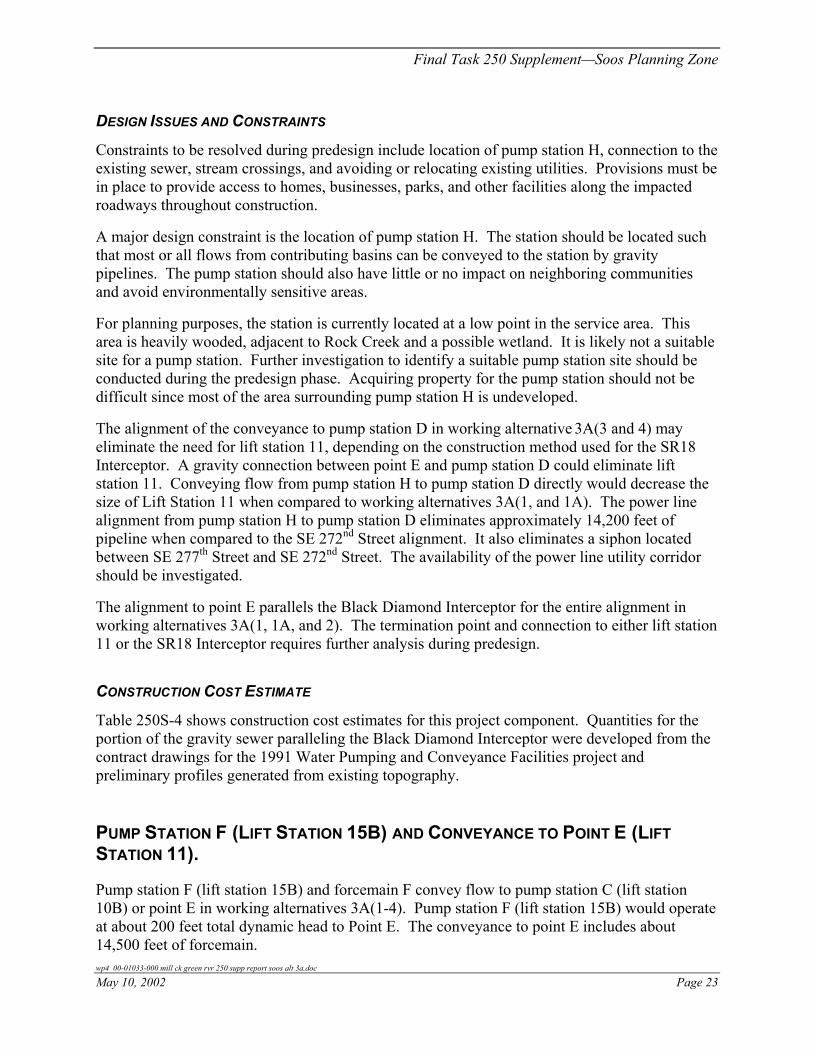
PUMP STATION F (LIFT STATION 15B) AND CONVEYANCE TO POINT E (LIFT STATION 11).
Pump station F (lift station 15B) and forcemain F convey flow to pump station C (lift station 10B) or point E in working alternatives 3A(1-4). Pump station F (lift station 15B) would operate at about 200 feet total dynamic head to Point E. The conveyance to point E includes about 14,500 feet of forcemain. wp4 00-01033-000 mill ck green rvr 250 supp report soos alt 3a.doc
May 10, 2002 Page 23

Final Task 250 Supplement—Soos Planning Zone
Table 250S-4. Estimated Construction Cost - Pump Station H and Conveyance to Pump Station D or Point E.
Working Alternative Project
Average Depth
(ft) Quantity Unit
Estimated Construction Cost a
(million dollars)
Pump Station H Pump Station H – 1 LS $ 2,400,000
Forcemain H (open cut construction) 12 inch 6 1,000 LF $ 282,000
Pipeline (open cut construction) Power Line Varies 35,300 LF $19,700,000 SE 272nd Street Varies 49,500 LF $24,000,000 Point E Varies 35,000 LF $18,279,000
Pump Station H Total (Power Line) $22,382,000 Pump Station H Total (SE 272nd Street) $26,682,000
Pump Station H Total (Point E) $20,961,000 a County Estimate 2002 dollars
A portion of the flow from pump station F (lift station 15B) discharges to point E in working alternatives 3A(1-4). This portion of pump station F’s (lift station 15B’s) flow will discharge to lift station 11 or the SR18 Interceptor, depending on the configuration of the downstream components. Pump station F (lift station 15B) currently conveys flow to lift station 10, which will be replaced by pump station C (lift station 10B).
The following photographs depict existing conditions along forcemain F’s alignment. The approximate location of each photo is indicated in Figure 250S-5. A brief description of access concerns for each representative section of the proposed alignment is included.
The alignment presented follows an existing easement and developed roadways. Further investigation to determine the status and boundaries of the easement should be conducted during predesign.
The project alignment is not shown in preliminary plan and profile sheets at the end of this project discussion. Preliminary plan and profiles were included in the Final Task 250 Supplement Report for Soos Creek dated July 2001. The District may have adequate capacity in existing forcemains from SE 256th Street to pump station C (lift station 10B).
PROJECT IMPACTS
Typical temporary construction related impacts may include increased noise, dust and construction vehicle traffic. Temporary partial road closures may be required. Trees and other vegetation may be impacted by pipeline and pump station excavation.
Impacts to citizens, businesses, and the environment are of concern with proposed interceptor alignments. Access to neighboring residences and businesses must be maintained throughout construction. Impacts to traffic are expected.
wp4 00-01033-000 mill ck green rvr 250 supp report soos alt 3A.doc
Page 24 May 10, 2002

#Y#Y#Y
#Y
$T
#S$T
SE 240th St
180th
Ave
SE
SE Wax Rd
196th
Ave
SE
SE Wax Rd
SE 272nd St
Maple Val- Blk Diam
Rd
Map produced by GIS staff, Wastewater Treatment Division (WTD), King CountyDepartment of Natural Resources. WTD disclaims any warranty for use of this digitalproduct beyond that for which it was designed. Neither this digital product,nor any portion thereof may be reproduced in any form or by any means without the expressed written authorization of WTD. This document includesdata copyrighted by the Kroll Map Company and is being used with their permission. Use is restricted.
600 0 600 1200 1800 2400 3000 Feet
N
EW
SMarch 20, 2002
Figure 250 S - 5 : Soos Planning Zone
i:\gis\projects\csi project\projects\MC_GR area\task250\project\task250_sup_soos2.apr
P2
P3
SR 18
PS F Forcemain
PS F Gravity Sewer
E
PS F
Mill Creek / Green River Subregional Planning AreaWorking Alternative Component - PS F and Conveyance to Point E
Legend Photo Reference Point
StreamUrban Growth Line 2000South Interceptor IIIMC/GR BoundaryStreets - FreewaysMC/GR Sewerlines
%U MC/GR King Co Pump Stations
County Boundary
Proposed SewersProposed GravityProposed ForcemainExisting Local GravityExisting Local Forcemain
Railroad
MC/GR Local PS"G Local PS Continues
%I Local PS Eliminated
Conveyance Sites"A Reference Point
$B Proposed Regional PS
$B Existing Local PS
Flow Projection AreaABCDFGH
P1


Final Task 250 Supplement—Soos Planning Zone
P2: SE Wax Road – SE 240th Street to 180th Avenue SE
P1: 215th Avenue SE – Pump Station F (Lift Station 15B) to Easement Access to businesses, homes, and adjacent
roadways must be maintained.
Vehicular access will probably be impossible to maintain due to the limited space available for sewer construction. Access to homes and Lift Station 15B must be maintained.
P2
P1
P3: 180th Ave SE – SE Wax Rd to SR18
Access to businesses, homes, and adjacent roadways must be maintained.
P3
Streams should not be impacted by pipeline construction. Eliminating impacts may be accomplished by jacking or tunneling. A minimum separation of five feet is recommended between streambed and pipe crown in order to allow for natural streambed movement. Jacking and receiving pits should be placed away from the streambank to avoid erosion.
wp4 00-01033-000 mill ck green rvr 250 supp report soos alt 3a.doc
May 10, 2002 Page 27

Final Task 250 Supplement—Soos Planning Zone
Table 250S-5 includes existing utilities and roadway characteristics observed during planning level field inspection along pump station F’s (lift station 15B) conveyance alignment.
Table 250S-5. Existing Conditions - Pump Station F (Lift Station 15B) and Conveyance to Point E (Lift Station 11).
Road Way
Type Traffic Lanes
Parking Lanes
Conveyance Component Alignment U
nder
grou
nd
Tele
phon
e W
ater
Se
wer
St
orm
Dra
in
Gas
O
verh
ead
Pow
er
Und
ergr
ound
Pow
er
Bike
Lan
es
Side
wal
k St
ream
Cro
ssin
g
Ease
men
t St
reet
Tre
es
Airp
ort
Maj
or A
rteria
l Se
cond
ary
Arte
rial
Col
lect
or
Loca
l 1 2 5 1 2
P1 215th Ave SE – Pump Station F (Lift Station 15B) to Easement
X X X X X X
P2 SE Wax Rd – SE 240th Street to 180th Ave SE
X X X X X X X
P3 180th Ave SE – SE Wax Rd to SR18
X X X X X X X X X X
PERMIT REQUIREMENTS
A ROW use permit from King County Roads Department is required for construction within the right of way. The discharge from dewatering operations may require a section 401 water quality certificate form the Washington Department of Ecology or a King County Industrial Waste Discharge Permit. A SEPA checklist is required. Documentation associated with the Endangered Species Act may be required. A building permit will be required for the pump station. A Hydraulic Project Approval will be required at non-tunneled stream crossings; however, the County generally, as a matter of course, does not cut through streams, creeks, or rivers.
EASEMENT AND PROPERTY ACQUISITION
Property acquisitions may be necessary for pump station F (lift station 15B). Further investigation to identify suitable pump station sites should be conducted during project predesign if the existing lift station is not adequate or if lift station 15B must be kept online during construction of an upgraded station.
wp4 00-01033-000 mill ck green rvr 250 supp report soos alt 3A.doc
Page 28 May 10, 2002
Final Task 250 Supplement—Soos Planning Zone
OPERATION AND MAINTENANCE
Pump station F’s (lift station 15B) conveyance is a forcemain. No routine or scheduled maintenance is anticipated for this type of pipeline.
Pump stations have specific O&M requirements depending on configuration, frequency of use, and other factors. In general, design considerations to reduce labor, parts replacement and downtime should be considered during predesign.
DESIGN ISSUES AND CONSTRAINTS
Constraints to be resolved during design include connection to the existing sewer, location of pump station F (lift station 15B), stream crossings, and avoiding or relocating existing utilities. In general, provisions must be in place to provide access to homes, businesses, and pump station F’s (lift station 15B’s) pipeline alignment throughout construction.
A major design constraint is the location of pump station F (lift station 15B). The station should be located such that most or all flows from contributing basins can be conveyed to the station by gravity pipelines. It should also have little or no impact on neighboring communities and avoid environmentally sensitive areas.
For planning purposes, pump station F (lift station 15B) is located adjacent to lift station 15B. If the station were south of its current location it would have a larger service area. In the current location, conveyance facilities would be required to convey flows from the southern portions of the service area. Suitable pump station sites should be identified during the predesign phase.
Connection to point E and the SE 256th Street forcemain(s) needs to be resolved. Discharging to two systems presents unique hydraulic impacts to pump station F (lift station 15B) and should be considered during design of the facility.
CONSTRUCTION COST ESTIMATE
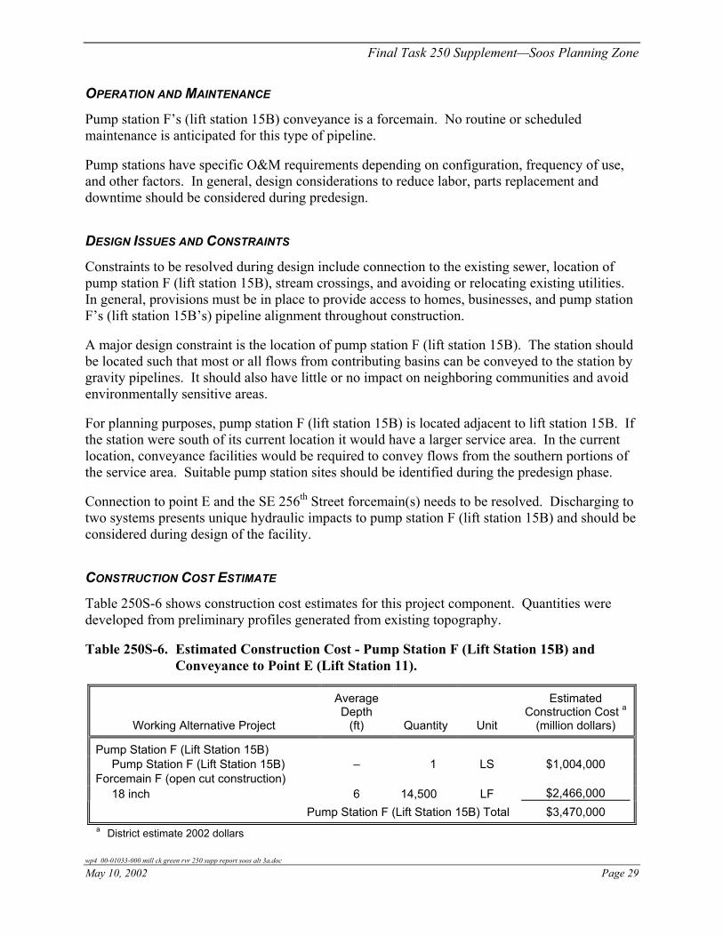
Table 250S-6 shows construction cost estimates for this project component. Quantities were developed from preliminary profiles generated from existing topography.
Table 250S-6. Estimated Construction Cost - Pump Station F (Lift Station 15B) and Conveyance to Point E (Lift Station 11).
Working Alternative Project
Average Depth
(ft) Quantity Unit
Estimated Construction Cost a
(million dollars)
Pump Station F (Lift Station 15B) Pump Station F (Lift Station 15B) – 1 LS $1,004,000
Forcemain F (open cut construction) 18 inch 6 14,500 LF $2,466,000
Pump Station F (Lift Station 15B) Total $3,470,000 a District estimate 2002 dollars
wp4 00-01033-000 mill ck green rvr 250 supp report soos alt 3a.doc
May 10, 2002 Page 29

Final Task 250 Supplement—Soos Planning Zone
CONVEYANCE FROM POINT E/LIFT STATION 11 TO PUMP STATION D - SR18 INTERCEPTOR
The SR18 Interceptor is located along SR18 from point E to pump station D and conveys flow greater than 14.4 mgd from pump station F (lift station 15B), pump station C’s (lift station 10B) local service area, and lift station 11’s local service area to pump station D in working alternatives 3A(3 and 4). Flow from pump station H is included in the total flow received at point E in working alternatives 3A(1, 1A, and 2).
Lift station 11 conveys flow through a forcemain to the SR18 Interceptor in working alternatives 3A(1, 1A, 3, and 4). Lift station 11 is eliminated in working alternative 3A(2), and flow is conveyed to a microtunneled SR18 Interceptor by gravity. The SR18 Interceptor includes about 10,000 feet of open cut construction or a combination of open cut and microtunneled gravity sewer.
The following photograph depicts existing conditions along the proposed gravity interceptor. Included is a brief description of access concerns for the proposed alignment.
P1: SR18 – Point E to Pump Station D
Access to SR18 must be maintained. Construction along SR18 may require alternate methods of construction such as microtunneling.
P1
PROJECT IMPACTS
Typical temporary construction related impacts may include increased noise, dust and construction vehicle traffic. Temporary partial road closures may be required. Trees or other vegetation may be impacted by excavation.
wp4 00-01033-000 mill ck green rvr 250 supp report soos alt 3A.doc
Page 30 May 10, 2002

Final Task 250 Supplement—Soos Planning Zone
Impacts to citizens, businesses, and the environment are of concern along interceptor alignments. Access to neighboring residences and businesses must be maintained throughout construction. Impacts to traffic are expected.
Streams should not be impacted by construction. Jacking or tunneling pipeline construction methods would eliminate impacts to streams. A minimum separation of five feet is recommended between streambed and pipe crown in order to allow for natural streambed movement. Jacking and receiving pits should be placed away from the streambank to avoid erosion.
Table 250S-7 lists existing utilities and roadway characteristics observed during planning level field inspection along the SR18 Interceptor alignment.
Table 250S-7. Existing Conditions - Conveyance from Point E/Lift Station 11 to Pump Station D - SR18 Interceptor.
Roadway
Type Traffic Lanes
ParkingLanes
Conveyance Component Alignment U
nder
grou
nd
Pow
er
Wat
er
Sew
er
Stor
m D
rain
G
as
Ove
rhea
d Po
wer
U
nder
grou
nd
Pow
erBi
ke L
ane
Side
wal
k St
ream
Cro
ssin
g Ea
sem
ent
Stre
et T
rees
H
ighw
ay
Maj
or A
rteria
l Se
cond
ary
Arte
rial
Col
lect
or
Loca
l 2 4 1 2
P1 SR18 - Point E to Pump Station D
X X X X
PERMIT REQUIREMENTS
Work within SR18’s right of way will require a Franchise from the Washington State Department of Transportation. The discharge from dewatering operations may require a section 401 water quality certificate form the Washington Department of Ecology or a King County Industrial Waste Discharge Permit. A SEPA checklist is required. Documentation associated with the Endangered Species Act may be required. A Hydraulic Project Approval will be required at non-tunneled stream crossings; however, the County generally, as a matter of course, does not cut through streams, creeks, or rivers.
EASEMENT AND PROPERTY ACQUISITION
Easements are not anticipated for the SR18 Interceptor. If open cut methods of installation are used, property acquisitions will likely not be required.
wp4 00-01033-000 mill ck green rvr 250 supp report soos alt 3a.doc
May 10, 2002 Page 31

Final Task 250 Supplement—Soos Planning Zone
OPERATION AND MAINTENANCE
The SR18 Interceptor includes a gravity sewer. No routine or scheduled maintenance is anticipated for this type of pipeline.
DESIGN ISSUES AND CONSTRAINTS
Constraints to be resolved during design include avoiding or relocating existing utilities, stream crossings, and connection to gravity sewers and pump station D. Provisions must be in place to provide access to impacted roadways throughout construction.
Critical elevations for the proposed alternative are the upstream connection at point E and the connection to pump station D. The SR18 interceptor may require open cut or microtunneled forms of construction depending on the final elevations to be refined in full predesign.
CONSTRUCTION COST ESTIMATE
Table 250S-8 shows construction cost estimates for this project component. Quantities were developed from preliminary profiles generated from existing topography.
Table 250S-8. Estimated Construction Cost - Conveyance from Point E/Lift Station 11 to Pump Station D - SR18 Interceptor.
Working Alternative Project
Average Depth
(ft) Quantity Unit
Estimated Construction Cost a
(million dollars)
Lift Station 11 Lift Station 11 (Alt 3A(1) d and 3A(1A) e) - 1 LS $ 3,810,000 Lift Station 11 (Alt 3A(3 and 4)) - 1 LS $ 1,121,000 c
Forcemain Lift Station 11/GS SR18 Alt 3A(1) d and 3A(1A) e FM and GS LS $ 7,430,000 b Alt 3A(3 and 4) - FM and GS LS $ 3,387,000 c Alt 3A(2) - GS LS $11,113,000 b
SR18 Interceptor & Lift Station 11 (Alt 3A(1) d and 3A(1A) e) Total $11,240,000 b SR18 Interceptor & Lift Station 11 (Alt 3A(3 and 4)) Total $ 4,508,000 c
SR18 Interceptor & Lift Station 11 (Alt 3A(2)) Total $11,113,000 b a 2002 dollars b County estimate c District estimate for comparison and reference d County-owned/County-built e County-owned/District-built
wp4 00-01033-000 mill ck green rvr 250 supp report soos alt 3A.doc
Page 32 May 10, 2002

Final Task 250 Supplement—Soos Planning Zone
PUMP STATION B AND CONVEYANCE TO PUMP STATION D
This component project includes pump station B, and conveyance to pump station D as shown in Figure 250S-6. Pump station B operates at about 171 feet total dynamic head. Conveyance to Pump station D includes approximately 5,500 feet and 4,300 feet of forcemain and gravity sewer respectively. Conveyance to Pump station D is routed northeast along SR18 to pump station D.
The following photographs depict existing conditions along the proposed forcemain alignment. The approximate location of each photo is indicated in Figure 250S-6. A brief description of access concerns for each representative section of the proposed alignment is included.
P1: SR18 – Pump Station B to Pump Station D
Roadway and shoulder access must be maintained.
P1
The project alignment was shown on preliminary plan and profile sheets in the Final Task 250 Supplement Report for Soos Creek and will not be included in this report.
PROJECT IMPACTS
Typical temporary construction related impacts may include increased noise, dust and construction vehicle traffic. Temporary partial road closures may be required. Trees and other vegetation may be impacted by pipeline and pump station excavation.
Impacts to citizens, businesses, and the environment are of concern with interceptor alignments. Access to neighboring residences and businesses must be maintained throughout construction. Impacts to traffic are expected.
wp4 00-01033-000 mill ck green rvr 250 supp report soos alt 3a.doc
May 10, 2002 Page 33
Final Task 250 Supplement—Soos Planning Zone
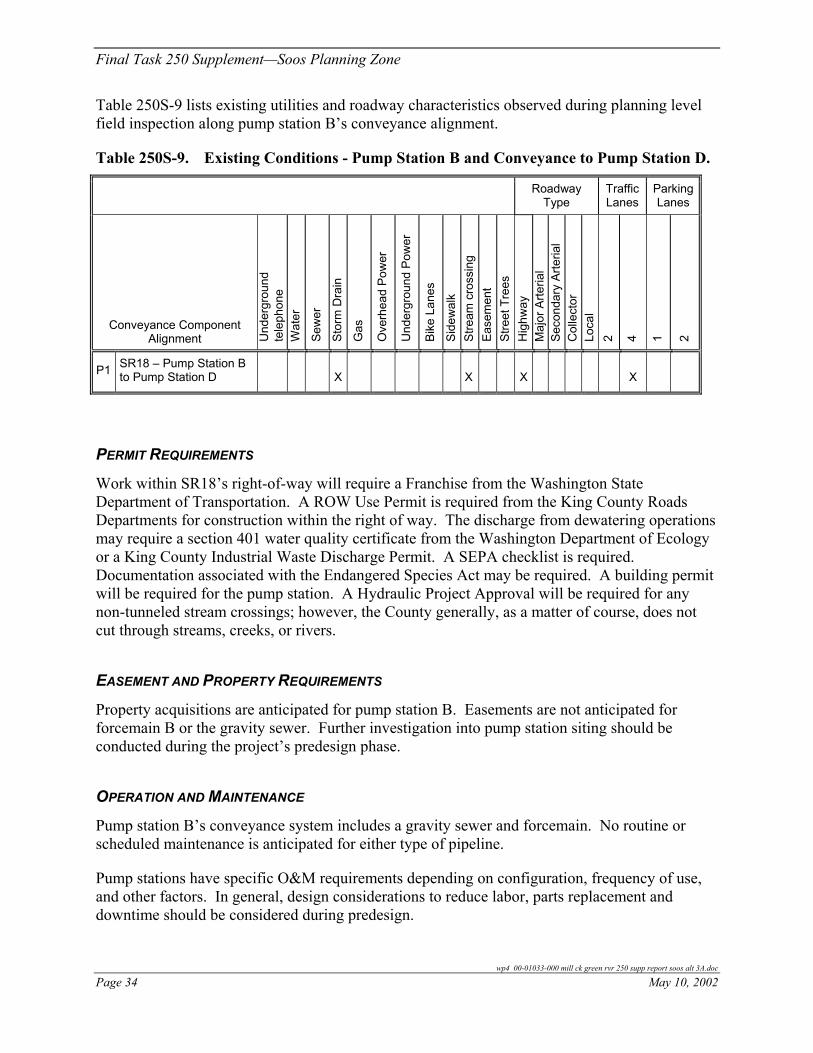
Table 250S-9 lists existing utilities and roadway characteristics observed during planning level field inspection along pump station B’s conveyance alignment.
Table 250S-9. Existing Conditions - Pump Station B and Conveyance to Pump Station D.
Roadway
Type Traffic Lanes
Parking Lanes
Conveyance Component Alignment U
nder
grou
nd
tele
phon
e W
ater
Sew
er
Stor
m D
rain
Gas
Ove
rhea
d Po
wer
Und
ergr
ound
Pow
er
Bike
Lan
es
Side
wal
k St
ream
cro
ssin
g Ea
sem
ent
Stre
et T
rees
H
ighw
ay
Maj
or A
rteria
l Se
cond
ary
Arte
rial
Col
lect
o r
Loca
l 2 4 1 2
P1 SR18 – Pump Station B to Pump Station D X X X X
PERMIT REQUIREMENTS
Work within SR18’s right-of-way will require a Franchise from the Washington State Department of Transportation. A ROW Use Permit is required from the King County Roads Departments for construction within the right of way. The discharge from dewatering operations may require a section 401 water quality certificate from the Washington Department of Ecology or a King County Industrial Waste Discharge Permit. A SEPA checklist is required. Documentation associated with the Endangered Species Act may be required. A building permit will be required for the pump station. A Hydraulic Project Approval will be required for any non-tunneled stream crossings; however, the County generally, as a matter of course, does not cut through streams, creeks, or rivers.
EASEMENT AND PROPERTY REQUIREMENTS
Property acquisitions are anticipated for pump station B. Easements are not anticipated for forcemain B or the gravity sewer. Further investigation into pump station siting should be conducted during the project’s predesign phase.
OPERATION AND MAINTENANCE
Pump station B’s conveyance system includes a gravity sewer and forcemain. No routine or scheduled maintenance is anticipated for either type of pipeline.
Pump stations have specific O&M requirements depending on configuration, frequency of use, and other factors. In general, design considerations to reduce labor, parts replacement and downtime should be considered during predesign.
wp4 00-01033-000 mill ck green rvr 250 supp report soos alt 3A.doc
Page 34 May 10, 2002

#Y
#Y
#Y #Y
%[
%[
%[#Y
%[
%[
#Y
$T
$T
124
SE Wax
Rd
SE 312th St
burn
Black
Diam
ond R
d
Kangley Rd
Kent Black Diamond Rd
132n
d Ave
SE
152n
d Ave
SE
Map produced by GIS staff, Wastewater Treatment Division (WTD), King CountyDepartment of Natural Resources. WTD disclaims any warranty for use of this digitalproduct beyond that for which it was designed. Neither this digital product,nor any portion thereof may be reproduced in any form or by any means without the expressed written authorization of WTD. This document includesdata copyrighted by the Kroll Map Company and is being used with their permission. Use is restricted.
600 0 600 1200 1800 2400 3000 Feet
N
EW
SMay 6, 2002
Figure 250 S - 6 : Soos Planning Zone
i:\gis\projects\csi project\projects\MC_GR area\task250\project\task250_sup_soos2.apr
PS B
PS D
SR 18288th
140t
h
Mill Creek / Green River Subregional Planning AreaWorking Alternative Component -PS B and Conveyance to PS D
Legend Photo Reference Point
StreamUrban Growth Line 2000South Interceptor IIIMC/GR BoundaryStreets - FreewaysMC/GR Sewerlines
%U MC/GR King Co Pump Stations
County Boundary
Proposed SewersProposed GravityProposed ForcemainExisting Local GravityExisting Local Forcemain
Railroad
MC/GR Local PS"G Local PS Continues
%I Local PS Eliminated
Conveyance Sites"A Reference Point
$B Proposed Regional PS
$B Existing Local PS
Flow Projection AreaABCDFGH
P1


Final Task 250 Supplement—Soos Planning Zone
DESIGN ISSUES AND CONSTRAINTS
Constraints to be resolved during design include connection to the existing sewer, location of pump station B, stream crossings, and avoiding or relocating existing utilities. In general, provisions must be in place to provide access to homes and businesses along the alignment throughout construction. The operation of SR18 must be maintained throughout construction.
A major design constraint is the location of pump station B. The station should be located such that most or all flows from contributing basins can be conveyed to the station by gravity pipelines. It should also have little or no impact on neighboring communities and avoid environmentally sensitive areas.
Field investigations were performed to determine suitable locations for pump station B. Several siting areas of interest are shown in Figure 250S-7. The general pump station siting area of interest is a low point in the service area along SR18 and SE 304th Street. The area surrounding the area of interest is largely developed. Further investigation into a suitable site should be conducted during the projects predesign phase.
CONSTRUCTION COST ESTIMATE
Table 250S-10 shows construction cost estimates for this project component. Quantities were developed from preliminary profiles generated from existing topography.
Table 250S-10. Estimated Construction Cost - Pump Station B and Conveyance to Pump Station D.
Working Alternative Project
Average Depth
(ft) Quantity Unit
Estimated Construction Cost a
(million dollars)
Pump Station B Pump Station B - 1 LS $3,030,000
Forcemain B (open cut construction) 12 inch 6 5,500 LF $1,530,000
Gravity Sewer B 12 inch 7 2,600 LF $ 780,000 18 inch 4 1,700 LF $ 552,000
Lift Station B Total $5,892,000 a County estimate in 2002 dollars
PUMP STATION D AND CONVEYANCE TO POINT A A regional pump station (pump station D), forcemain D, and gravity sewer convey flow to point A as shown in Figure 250S-8. Pump station D operates at about 163 feet total dynamic head. Conveyance to point A includes about 16,200 feet and 5,400 feet of forcemain and gravity sewer respectively. Forcemain D transitions to gravity sewer approximately half way between 118th Avenue SE and 124th Avenue SE. The gravity sewer continues along local roadways to its connection with the 277th Interceptor. wp4 00-01033-000 mill ck green rvr 250 supp report soos alt 3a.doc
May 10, 2002 Page 37
Final Task 250 Supplement—Soos Planning Zone
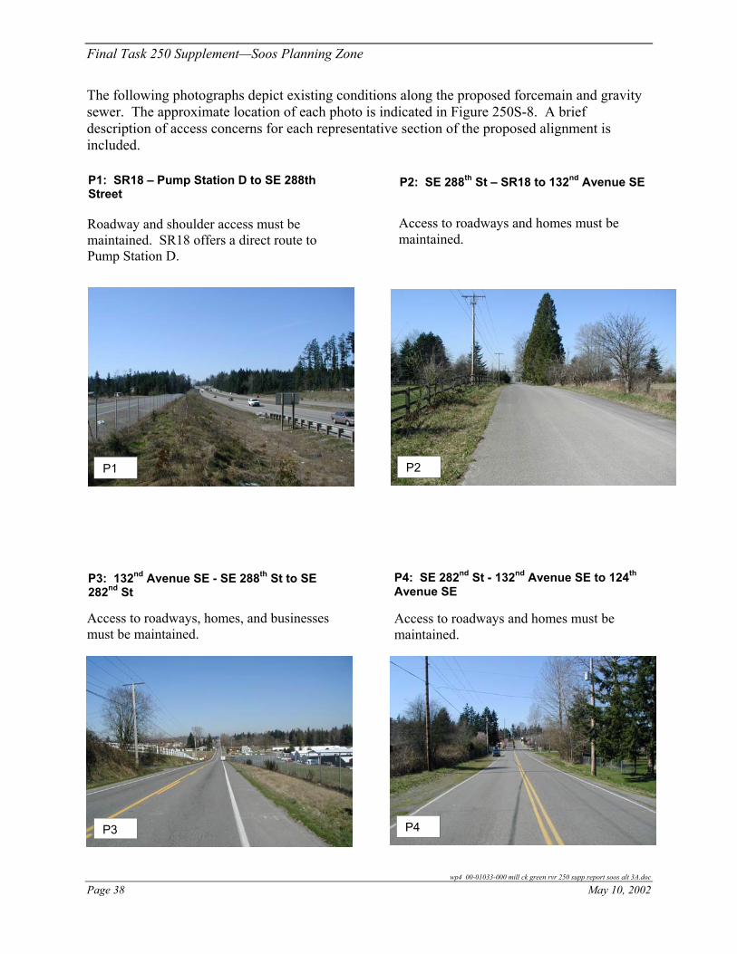
The following photographs depict existing conditions along the proposed forcemain and gravity sewer. The approximate location of each photo is indicated in Figure 250S-8. A brief description of access concerns for each representative section of the proposed alignment is included.
wp4 00-01033-000 mill ck green rvr 250 supp report soos alt 3A.doc
May 10, 2002 Page 38
P1: SR18 – Pump Station D to SE 288th Street
P2: SE 288th St – SR18 to 132nd Avenue SE
Access to roadways and homes must be maintained.
Roadway and shoulder access must be maintained. SR18 offers a direct route to Pump Station D.
P1 P2
P4: SE 282nd St - 132nd Avenue SE to 124th
Avenue SE
P3: 132nd Avenue SE - SE 288th St to SE 282nd St
Access to roadways, homes, and businesses must be maintained.
Access to roadways and homes must be maintained.
P4
P3

$T
132n
d Ave
SE
132n
d Ave
SE
Map produced by GIS staff, Wastewater Treatment Division (WTD), King CountyDepartment of Natural Resources. WTD disclaims any warranty for use of this digitalproduct beyond that for which it was designed. Neither this digital product,nor any portion thereof may be reproduced in any form or by any means without the expressed written authorization of WTD. This document includesdata copyrighted by the Kroll Map Company and is being used with their permission. Use is restricted. 90 0 90 180 270 360 450 Feet
N
EW
S
Figure 250 S - 7 : Soos Planning Zone
March 20, 2002
Legend
Mill Creek / Green River Subregional Planning AreaPump Station B Siting Areas of Interest
SR 18
SE 304th St
137th
299th 138th
297th
301st PS B
StreamUrban Growth Line 2000
Proposed SewersProposed GravityProposed ForcemainExisting Local GravityExisting Local Forcemain
Conveyance Sites
$B Proposed Regional PS
$B Existing Local PS
Pump Station Area of InterestStreets - Local
i:\gis\projects\csi project\projects\MC_GR area\task250\project\task250_sup_soos2.apr
Pump StationArea of Interest (typ)


#Y
#Y
#Y#Y
#Y #Y
%[
%[
%[
%[
%[
#Y
$T
$T
$T
SE 256th St
124th
Ave
SE
Trunk
Kent Kangley Rd
132n
d Ave
SE
152n
d Ave
SE
Map produced by GIS staff, Wastewater Treatment Division (WTD), King CountyDepartment of Natural Resources. WTD disclaims any warranty for use of this digitalproduct beyond that for which it was designed. Neither this digital product,nor any portion thereof may be reproduced in any form or by any means without the expressed written authorization of WTD. This document includesdata copyrighted by the Kroll Map Company and is being used with their permission. Use is restricted.
500 0 500 1000 1500 2000 2500 Feet
N
EW
SMay 6, 2002
Figure 250 S - 8 : Soos Planning Zone
PS C
A
PS B
288th
282nd
277 th
SR 18
SE 272nd St
i:\gis\projects\csi project\projects\MC_GR area\task250\project\task250_sup_soos2.apr
Mill Creek / Green River Subregional Planning AreaWorking Alternative Component - PS D and Conveyance to Point A
"A
Legend Photo Reference Point
StreamUrban Growth Line 2000South Interceptor IIIMC/GR BoundaryStreets - FreewaysMC/GR Sewerlines
%U MC/GR King Co Pump Stations
County Boundary
Proposed SewersProposed GravityProposed ForcemainExisting Local GravityExisting Local Forcemain
Railroad
MC/GR Local PS"G Local PS Continues
%I Local PS Eliminated
Conveyance Sites"A Reference Point
$B Proposed Regional PS
$B Existing Local PS
P2
P3
P4 P5
P8
P9 P7
P1 PS D
Flow Projection AreaABCDFGH
P6


Final Task 250 Supplement—Soos Planning Zone
P5: 124th Avenue SE - SE 282nd St to SE 284th St
P6: SE 284th St - 124th Avenue SE to 118th Avenue SE
Access to roadways and homes must be maintained. The pipeline’s alignment does not continue along SE 282nd St because there appears to be a wetland area west of 124th Avenue SE.
Access to roadways and homes must be maintained.
P6
P5
P8: SE 277th Pl - 118th Avenue SE to 114th Avenue SE
P7: 118th Avenue SE - SE 284th St to SE 277th Pl Access to the elementary school’s parking
lot and playground must be maintained.
Access to roadways and homes must be maintained.
P7 P8
wp4 00-01033-000 mill ck green rvr 250 supp report soos alt 3a.doc
May 10, 2002 Page 43

Final Task 250 Supplement—Soos Planning Zone
P9: 114th Avenue SE - SE 277th Pl to SE 274th St
Access to roadways and homes must be maintained.
P9
The project alignment is not shown in preliminary plan and profile sheets at the end of this project discussion. Preliminary plan and profiles were included in the Final Task 250 Supplement Report for Soos Creek.
PROJECT IMPACTS Typical temporary construction related impacts may include increased noise, dust and construction vehicle traffic. Temporary partial road closures may be required. Trees and other vegetation may be impacted by pipeline and pump station excavation.
Impacts to citizens, businesses, and the environment are of concern with interceptor alignments. Access to neighboring residences and businesses must be maintained throughout construction. Impacts to traffic are expected.
Streams should not be impacted by construction. Jacking or tunneling pipeline construction methods would eliminate impacts to streams. A minimum separation of five feet is recommended between streambed and pipe crown in order to allow for natural streambed movement. Jacking and receiving pits should be placed away from the streambank to avoid erosion.
Table 250S-11 lists existing utilities and roadway characteristics observed during planning level field inspection along pump station D’s conveyance alignment.
wp4 00-01033-000 mill ck green rvr 250 supp report soos alt 3A.doc
Page 44 May 10, 2002
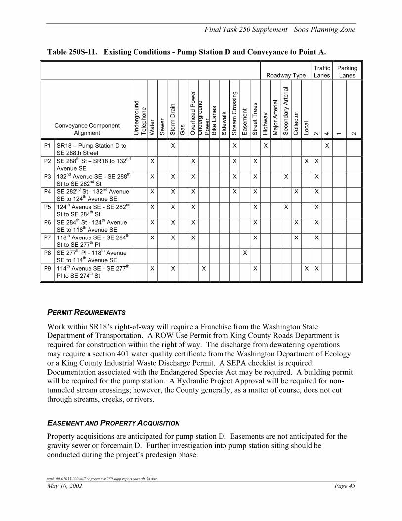
Final Task 250 Supplement—Soos Planning Zone
Table 250S-11. Existing Conditions - Pump Station D and Conveyance to Point A.
Roadway Type Traffic Lanes
Parking Lanes
Conveyance Component Alignment U
nder
grou
nd
Tele
phon
e W
ater
Sew
er
Stor
m D
rain
Gas
Ove
rhea
d Po
wer
U
nder
grou
nd
Pow
er
Bike
Lan
es
Side
wal
k
Stre
am C
ross
ing
Ease
men
t
Stre
et T
rees
Hig
hway
Maj
or A
rteria
l
Seco
ndar
y Ar
teria
l
Col
lect
or
Loca
l
2 4 1 2
P1 SR18 – Pump Station D to SE 288th Street
X X X X
P2 SE 288th St – SR18 to 132nd Avenue SE
X X X X X X
P3 132nd Avenue SE - SE 288th St to SE 282nd St
X X X X X X X
P4 SE 282nd St - 132nd Avenue SE to 124th Avenue SE
X X X X X X X
P5 124th Avenue SE - SE 282nd St to SE 284th St
X X X X X X
P6 SE 284th St - 124th Avenue SE to 118th Avenue SE
X X X X X X
P7 118th Avenue SE - SE 284th St to SE 277th Pl
X X X X X X
P8 SE 277th Pl - 118th Avenue SE to 114th Avenue SE
X
P9 114th Avenue SE - SE 277th Pl to SE 274th St
X X X X X X
PERMIT REQUIREMENTS
Work within SR18’s right-of-way will require a Franchise from the Washington State Department of Transportation. A ROW Use Permit from King County Roads Department is required for construction within the right of way. The discharge from dewatering operations may require a section 401 water quality certificate from the Washington Department of Ecology or a King County Industrial Waste Discharge Permit. A SEPA checklist is required. Documentation associated with the Endangered Species Act may be required. A building permit will be required for the pump station. A Hydraulic Project Approval will be required for non-tunneled stream crossings; however, the County generally, as a matter of course, does not cut through streams, creeks, or rivers.
EASEMENT AND PROPERTY ACQUISITION Property acquisitions are anticipated for pump station D. Easements are not anticipated for the gravity sewer or forcemain D. Further investigation into pump station siting should be conducted during the project’s predesign phase.
wp4 00-01033-000 mill ck green rvr 250 supp report soos alt 3a.doc
May 10, 2002 Page 45

Final Task 250 Supplement—Soos Planning Zone
OPERATION AND MAINTENANCE Pump station D’s conveyance system includes a gravity sewer and forcemain. No routine or scheduled maintenance is anticipated for either type of pipeline.
Pump stations have specific O&M requirements depending on configuration, frequency of use, and other factors. In general, design considerations to reduce labor, parts replacement and downtime should be considered during predesign.
DESIGN ISSUES AND CONSTRAINTS
Constraints to be resolved during design include connection to the existing sewer, location of pump station D, stream crossings, and avoiding or relocating existing utilities. In general, provisions must be in place to provide access to homes and businesses along the alignment throughout construction. The operation of SR18 must be maintained throughout construction.
A major design constraint is the location of pump station D. The station should be located such that most or all flows from contributing basins can be conveyed to the station by gravity pipelines. It should also have little or no impact on neighboring communities and avoid environmentally sensitive areas.
Field investigations were performed to determine suitable locations for pump station D. Several siting areas of interest are shown in Figure 250S-9. The general pump station siting area of interest is a low point in the service area on the east side of SR18 at about SE 280th Street. Further investigation into a suitable site should be conducted during the projects predesign phase.
CONSTRUCTION COST ESTIMATE
Table 250S-12 shows construction cost estimates for this project component. Quantities were developed from preliminary profiles generated from existing topography.
Table 250S-12. Estimated Construction Cost-Pump Station D and Conveyance to Point A.
Working Alternative Projects
Average Depth
(ft) Quantity Unit
Estimated Construction Cost a
(million dollars)
Pump Station D Pump Station D – 1 LS $ 7,140,000
Forcemain D (open cut construction) 30 inch 6 16,200 LF $ 7,850,000
Pipeline (open cut construction) 24 inch 14 1,200 LF $ 699,000 36 inch 13 4,200 LF $ 3,060,000
Pump Station D Total $18,749,000 a County estimate 2002 dollars
wp4 00-01033-000 mill ck green rvr 250 supp report soos alt 3A.doc
Page 46 May 10, 2002

$T%[
#Y15
2nd A
ve S
E
Map produced by GIS staff, Wastewater Treatment Division (WTD), King CountyDepartment of Natural Resources. WTD disclaims any warranty for use of this digitalproduct beyond that for which it was designed. Neither this digital product,nor any portion thereof may be reproduced in any form or by any means without the expressed written authorization of WTD. This document includesdata copyrighted by the Kroll Map Company and is being used with their permission. Use is restricted.
200 0 200 400 600 800 1000 Feet
N
EW
S
Figure 250 S - 9 : Soos Planning Zone
March 20, 2002
Mill Creek / Green River Subregional Planning AreaPump Station D Siting Areas of Interest
i:\gis\projects\csi project\projects\MC_GR area\task250\project\task250_sup_soos2.apr
Streets - Local Pump Station Area of Interest
Existing Local PS$BProposed Regional PS$B
Conveyance Sites
Existing Local ForcemainExisting Local GravityProposed ForcemainProposed Gravity
Proposed Sewers
Urban Growth Line 2000Stream
Legend
Pump StationArea of Interest (typ)
PS DSR 18
280th
278th
273rd


Final Task 250 Supplement—Soos Planning Zone
TIMING
Two scenarios were developed in the Mill Creek/Green River Final Task 250 Report to address the Inflow and Infiltration (I/I) effects on the County’s system. The first scenario looked at reducing I/I by 20 percent in all Flow Projection Areas (FPAs), in all decades, under all storms. This type of reduction requires the rehabilitation of both existing and future sewers. The second scenario assumed that I/I is limited to 1,100 gallons per acre per day (gpad) for all new construction and avoids rehabilitation of existing sewers. In the 1,100 gpad scenario, the projections for new sewered area are escalated by a 7 percent per decade degradation factor. The result for the Soos Planning Zone was a reduction in peak flow of 17 percent for both of the scenarios. The 20 percent scenario alone may not yield results soon enough to impact the design of facilities required to provide capacity by the year 2010. Subsequent studies should investigate the feasibility of implementing the 1,100 gpad scenario in conjunction with working alternatives 3A(1-4). Direct costs will likely be much higher to implement the 20 percent scenario than the 1,100 gpad scenario. All I/I data and reduction scenarios will be refined and re-evaluated in predesign.
The required timing of County facilities in this report was evaluated based on no I/I reduction and a 17 percent reduction in peak flow.
The construction of pump station H drives the timing for all downstream projects. The timing of pump station H depends on when pump station G’s capacity of about 2.0 mgd is exceeded. With no I/I reduction program, this is projected to occur around the summer of 2005. Either the 20 percent or the 1,100 gpad scenario results in about a 17 percent reduction in peak flows. Therefore, implementation of either I/I program results in a need for pump station H in about 2007 as shown in Graph 250S-1.
The timing and sequencing of all other components is dependent on the timing requirements to bring pump station H on line. Therefore, if I/I reduction can be achieved, the need for all other components will be adjusted by a period of time similar to the adjusted time period for pump station H.
Changes in projected development and associated wastewater flows will also impact the required timing for pump station H and downstream facilities. According to the City of Black Diamond’s planning department, they currently have a moratorium on new subdivisions based on zoning issues. In addition, they do not currently have adequate water supply to serve new development. They are negotiating with the City of Tacoma to obtain adequate water supply. Both of these issues are expected to be resolved within the next few years, but may impact the speed of development.
The general timing of projects is shown in Figure 250S-10.
wp4 00-01033-000 mill ck green rvr 250 supp report soos alt 3a.doc
May 10, 2002 Page 49

03-1
9-02
/rtb/
HE
C-O
/00-
0103
3-00
0-24
0-00
4/D
raft
250
Sup
Rpt
Approximate scale
0 1 mile
Black Diamond Parallel Int.
Black Diamond Parallel Int.
Clark Fork Trunk
PS C
PS F
PS D
E
A
PS B
2005
2013
2005-2007
2010
2005-2007PS H
PS G
277th Interceptor SE 272nd StSR 18 Int.+
+
+2015
power line
Figure 250 S-10: Soos Planning ZoneMill Creek/Green River Subregional Planning AreaApproximate Component Timing

Final Task 250 Supplement—Soos Planning Zone
0.0
0.5
1.0
1.5
2.0
2.5
3.0
3.5
2002
2003
2004
2005
2006
2007
2008
2009
2010
Year
Flow
(mgd
)
Flow Projection - PS H (PS G + Local)Interpolation Fom Current Flow to 2010Predictions - No I/I Program
Flow Projection - PS H (PS G + Local)Interpolation Fom Current Flow to 2010Predictions + 17% reduction (I/I)
PS G Capacity
Graph 250S-1. Pump Station H Timing (Black Diamond Flow)
wp4 00-01033-000 mill ck green rvr 250 supp report soos alt 3a.doc
May 10, 2002 Page 51
