millennium ii basic single channel transmitter
TRANSCRIPT

Reference Manual Part Number: MAN-0082, rev. 08
Release: June 2016
Millennium II Basic Transmitter

Important Instructions Net Safety Monitoring, Inc (Net Safety) designs, manufactures and tests products to function within specific conditions. Because these products are sophisticated technical instruments, it is important that the owner and operation personnel must strictly adhere both to the information printed on the product nameplate and to all instructions provided in this manual prior to installation, operation, and maintenance.
Installing, operating or maintaining a Net Safety Product improperly could lead to serious injury or death from explosion or exposure to dangerous substances. Comply with all information on the product, in this manual, and in any local and national codes that apply to the product. Do not allow untrained personnel to work with this product. Use Net Safety parts and work procedures specified in this manual.

Notice The contents of this publication are presented for informational purposes only, and while every effort has been made to ensure their accuracy, they are not to be construed as warranties or guarantees, expressed or implied, regarding the products or services described herein or their use or applicability. All sales are governed by Net Safety’s terms and conditions, which are available upon request. We reserve the right to modify or improve the designs or specifications of such products at any time.
Net Safety does not assume responsibility for the selection, use or maintenance of any product. Responsibility for proper selection, use and maintenance of any Net Safety products remains solely with the purchaser and end-user.
To the best of Net Safety’s knowledge the information herein is complete and accurate. Net Safety makes no warranties, expressed or implied, including implied warranties of merchantability and fitness for a particular purpose with respect to this manual and, in no event, shall Net Safety be liable for any incidental, punitive, special or consequential damages including, but not limited to, loss of production, loss of profits, loss of revenue or use and costs incurred including without limitation for capital, fuel and power, and claims of third parties.
Product names used herein are for manufacturer or supplier identification only and may be trademarks/registered trademarks of these companies.
Net Safety and the Net Safety logo are registered trademarks of Net Safety Monitoring, Inc. The Emerson logo is a trademark and service mark of the Emerson Electric Company.
Copyright © 2016 by Rosemount, Shakopee, MN.
All rights reserved. No part of this work may be reproduced or copied in any form or by any means - graphic, electronic, or mechanical without first receiving written permission of Rosemount, Shakopee, MN.

Warranty 1. Limited Warranty. Subject to the limitations contained in Section 10 (Limitation of Remedy
and Liability) herein, Seller warrants that (a) the licensed firmware embodied in the Goods will execute the programming instructions provided by Seller; (b) that the Goods manufactured by Seller will be free from defects in materials or workmanship under normal use and care; and (c) Services will be performed by trained personnel using proper equipment and instrumentation for the particular Service provided. The foregoing warranties will apply until the expiration of the applicable warranty period. Sensors and detectors are warranted against defective parts and workmanship for 24 months from the date of purchase and other electronic assemblies for 36 months from the date of purchase. Products purchased by Seller from a third party for resale to Buyer (Resale Products) shall carry only the warranty extended by the original manufacturer. Buyer agrees that Seller has no liability for Resale Products beyond making a reasonable commercial effort to arrange for procurement and shipping of the Resale Products. If Buyer discovers any warranty defects and notifies Seller thereof in writing during the applicable warranty period, Seller shall, at its option, (i) correct any errors that are found by Seller in the firmware or Services; (ii) repair or replace FOB point of manufacture that portion of the Goods found by Seller to be defective; or (iii) refund the purchase price of the defective portion of the Goods/Services. All replacements or repairs necessitated by inadequate maintenance; normal wear and usage; unsuitable power sources or environmental conditions; accident; misuse; improper installation; modification; repair; use of unauthorized replacement parts; storage or handling; or any other cause not the fault of Seller, are not covered by this limited warranty and shall be replaced or repaired at Buyer’s sole expense and Seller shall not be obligated to pay any costs or charges incurred by Buyer or any other party except as may be agreed upon in writing in advance by Seller. All costs of dismantling, reinstallation, freight and the time and expenses of Seller’s personnel and representatives for site travel and diagnosis under this limited warranty clause shall be borne by Buyer unless accepted in writing by Seller. Goods repaired and parts replaced by Seller during the warranty period shall be in warranty for the remainder of the original warranty period or 90 days, whichever is longer. This limited warranty is the only warranty made by Seller and can be amended only in a writing signed by an authorized representative of Seller. The limited warranty herein ceases to be effective if Buyer fails to operate and use the Goods sold hereunder in a safe and reasonable manner and in accordance with any written instructions from the manufacturers. THE WARRANTIES AND REMEDIES SET FORTH ABOVE ARE EXCLUSIVE. THERE ARE NO REPRESENTATIONS OR WARRANTIES OF ANY KIND, EXPRESS OR IMPLIED, AS TO MERCHANTABILITY, FITNESS FOR PARTICULAR PURPOSE OR ANY OTHER MATTER WITH RESPECT TO ANY OF THE GOODS OR SERVICES.
2. Limitation of Remedy and Liability. SELLER SHALL NOT BE LIABLE FOR DAMAGES CAUSED BY DELAY IN PERFORMANCE. THE REMEDIES OF BUYER SET FORTH IN THE AGREEMENT ARE EXCLUSIVE. IN NO EVENT, REGARDLESS OF THE FORM OF THE CLAIM OR CAUSE OF ACTION (WHETHER BASED IN CONTRACT, INFRINGEMENT, NEGLIGENCE, STRICT LIABILITY, OTHER TORT OR OTHERWISE), SHALL SELLER’S LIABILITY TO BUYER AND/OR BUYER’S CUSTOMERS EXCEED THE PRICE TO BUYER OF THE SPECIFIC GOODS MANUFACTURED OR SERVICES PROVIDED BY SELLER GIVING RISE TO THE CLAIM OR CAUSE OF ACTION. BUYER AGREES THAT IN NO EVENT SHALL SELLER’S LIABILITY TO BUYER AND/OR BUYER’S CUSTOMERS EXTEND TO INCLUDE INCIDENTAL, CONSEQUENTIAL OR PUNITIVE DAMAGES. THE TERM “CONSEQUENTIAL DAMAGES” SHALL INCLUDE, BUT NOT BE LIMITED TO, LOSS OF ANTICIPATED PROFITS, REVENUE OR USE AND COSTS INCURRED INCLUDING WITHOUT LIMITATION FOR CAPITAL, FUEL AND POWER, AND CLAIMS OF BUYER’S CUSTOMERS.


Reference Manual Table of Contents MAN-0082, Revision 08 June 2016
Table of Contents i
Contents Section 1: Introduction ...................................................................... 1
1.1 Models covered ................................................................................................................... 1 1.2 Service support ................................................................................................................... 1 1.3 Return of material ............................................................................................................... 1 1.4 Product recycling/disposal .................................................................................................. 1
Section 2: Installation ........................................................................ 2 2.1 Unpacking and inspection ................................................................................................... 2 2.2 Dimensions ......................................................................................................................... 2 2.3 Mounting ............................................................................................................................ 2 2.4 Wiring ................................................................................................................................. 3
2.4.1 General requirements ........................................................................................... 3 2.4.2 Terminal connection ............................................................................................. 3 2.4.3 Cable choice and guidelines .................................................................................. 4 2.4.4 Important wiring guidelines .................................................................................. 4 2.4.5 External ground .................................................................................................... 5 2.4.6 Seals ..................................................................................................................... 5 2.4.7 Analog output, isolated supply, non-isolated supply and jumper configuration ..... 5
2.5 Wiring drawings .................................................................................................................. 7 2.6 Remote mounting of sensor ................................................................................................ 8
2.6.1 Wiring drawings for remote sensor wiring ............................................................. 9 2.7 Installation checklist .......................................................................................................... 10
Section 3: Operation ........................................................................ 11 3.1 Transmitter and faceplate description ............................................................................... 11 3.2 Intrusive access ................................................................................................................. 11 3.3 Non-intrusive access (magnetic Reed switch Access) ......................................................... 11
Section 4: Output configurations ..................................................... 13 4.1 Analog board assembly ..................................................................................................... 13 4.2 Analog/HART board assembly ........................................................................................... 14 4.3 Relay board assembly/configuration ................................................................................. 15 4.4 Digital board assembly/configuration................................................................................ 16
Section 5: Operation ........................................................................ 17 5.1 DIP switch settings ............................................................................................................ 17
5.1.1 Infrared sensor (SC311) gas curve selection ........................................................ 17 5.1.2 Hydrogen sulfide sensor (ST320) range selection ................................................ 17 5.1.3 Carbon monoxide sensor (ST360) range selection ............................................... 18 5.1.4 DIP switch settings for relay configuration .......................................................... 18 5.1.5 Digital Modbus DIP switch settings ..................................................................... 19 5.1.6 Analog and analog/HART DIP switch settings ...................................................... 20
Section 6: Calibration procedure ...................................................... 21 6.1 Calibration procedure ....................................................................................................... 21
6.1.1 Guidelines........................................................................................................... 21 6.1.2 Full calibration procedure ................................................................................... 21
6.2 Zeroing procedure ............................................................................................................ 22 6.3 Status conditions during calibration .................................................................................. 24 6.4 Calibration failures ............................................................................................................ 24 6.5 Manual reset ..................................................................................................................... 24
Table of Contents Reference Manual June 2016 MAN-0082, Revision 08
ii Table of Contents
Section 7: Monitoring and outputs .................................................. 25 7.1 Analog 4-20mA ................................................................................................................. 25 7.2 HART Communication (Optional) ...................................................................................... 25
7.2.1 HART Menu Structure ......................................................................................... 25 7.3 Relays (Optional) ............................................................................................................... 28
7.3.1 Alarm relays ........................................................................................................ 28 7.3.2 Fault relay ........................................................................................................... 28
7.4 RS-485 Modbus RTU (Optional) ......................................................................................... 28 7.4.1 Modbus registers ................................................................................................ 29
7.5 Transmitter output operation............................................................................................ 30 7.6 Fault monitoring ............................................................................................................... 31 7.7 Fault conditions ................................................................................................................ 31
7.7.1 Transmitter fault conditions ................................................................................ 31 7.7.2 Sensor fault conditions ....................................................................................... 32
Section 8: Maintenance ................................................................... 33 8.1 Periodic response check .................................................................................................... 33 8.2 Troubleshooting ............................................................................................................... 33 8.3 Storage ............................................................................................................................. 33 8.4 Spare parts and accessories ............................................................................................... 34
Section 9: Electrostatic sensitive device ........................................... 35
Section 10: Wire resistance table ....................................................... 36
Section 11: Specifications .................................................................. 37 11.1 Electrical ........................................................................................................................... 37
11.1.1 Operating voltage range ..................................................................................... 37 11.1.2 Power consumption ............................................................................................ 37 11.1.3 EMC compliance ................................................................................................. 37
11.2 Environmental................................................................................................................... 37 11.2.1 Operating temperature ...................................................................................... 37 11.2.2 Relative humidity ................................................................................................ 37 11.2.3 Ingress protection ............................................................................................... 37
11.3 Mechanical ........................................................................................................................ 37 11.3.1 Enclosure material .............................................................................................. 37 11.3.2 Conduit opening ................................................................................................. 37 11.3.3 Weight ............................................................................................................... 37
11.4 Warranty ........................................................................................................................... 38
Section 12: Certifications ................................................................... 39 12.1 North American................................................................................................................. 39 12.2 IECEx ................................................................................................................................. 39 12.3 FC Models ......................................................................................................................... 39
12.3.1 North America .................................................................................................... 39 12.3.2 IECEx .................................................................................................................. 39
Section 13: Ordering information ...................................................... 40

Reference Manual Introduction MAN-0082, Revision 08 June 2016
Introduction 1
Section 1: Introduction 1.1 Models covered
A Millennium II Basic gas detection system is composed of a field mounted transmitter and Millennium II series sensors which may be integrally mounted to the transmitter or remotely mounted.
The transmitter is certified for use in hazardous locations and is available as a single sensor system. Some operator controls including calibration can be accessed without opening the enclosure (housing) by using other communication devices and the attached magnet to actuate the reed switch. Available outputs are: conventional 4 to 20 mA analog, Analog/HART, electromechanical relays, or Modbus RTU digital.
1.2 Service support Technical support for this product can be provided by contacting your local Emerson Process Management representative or by contacting the Technical Support department at +1 866 347 3427 (toll free) or [email protected].
1.3 Return of material To expedite the return of this product, proper communication between the customer and the factory is important. Before returning a product, call +1 866 347 3427 (toll free) or e-mail [email protected] for a Return Material Authorization (RMA) number.
On the return of the equipment, include the following information:
1. RMA number provided to you by Rosemount 2. Company name and contact information 3. Ship all equipment, prepaid to:
Rosemount 6021 Innovation Boulevard Shakopee, MN 55379
4. Mark all packages with the RMA number and type of return (e.g. return for evaluation)
Pack items to protect them from damage and use anti-static bags or aluminum-backed cardboard as protection from electrostatic damage.
All equipment must be shipped prepaid. Collect shipments will not be accepted.
1.4 Product recycling/disposal Recycling of equipment and packaging should be taken into consideration and disposed of in accordance with local and national legislations/regulations.

Installation Reference Manual June 2016 MAN-0082, Revision 08
2 Installation
Section 2: Installation 2.1 Unpacking and inspection
Carefully remove all of the components from the packaging and verify them against the enclosed packing list. Inspect all components for any obvious damage such as broken or loose parts. If you find any components missing or damaged, notify your local Net Safety representative or the factory immediately.
2.2 Dimensions The Millennium II Basic transmitter enclosure is available in aluminum (6061) and stainless steel (SS316). Dimensions are provided in Figure 2-1 below.
Figure 2-1 Dimensions
A B C D E F G
in mm in mm in mm in mm in mm in mm in mm
Transmitter (AL) 4.8 122 3.6 91 3.6 91 4.8 122 5.1 130 0.3 7.6 3.0 76
Transmitter (SS) 4.7 119 3.6 91 3.6 91 4.7 119 5.1 130 0.3 7.6 3.2 81
2.3 Mounting Ensure transmitter and sensor are securely mounted as per local regulations. The transmitter has mounting holes to allow mounting to a wall or pole as desired. Mounting kit hardware is required when mounting the transmitter a pole. Contact your local Net Safety representative for detailed information on the pole mounting kits. The transmitter should be mounted at eye-level and be easily accessible for monitoring and maintenance purposes.
Reference Manual Installation MAN-0082, Revision 08 June 2016
Installation 3
2.4 Wiring
2.4.1 General requirements
Failure to follow these installation guidelines could result in death or serious injury. Ensure that only qualified personnel perform the installation.
Electrical shock could cause death or serious injury. Use extreme caution when making contact with the leads and terminals.
Do not open the transmitter, sensor, or junction box enclosure when in a classified area or when an explosive atmosphere may be present unless the power to the transmitter has been removed.
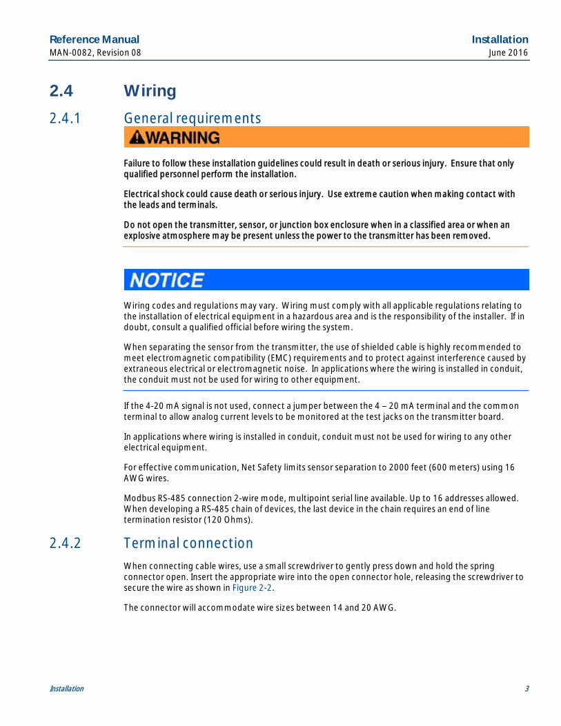
Wiring codes and regulations may vary. Wiring must comply with all applicable regulations relating to the installation of electrical equipment in a hazardous area and is the responsibility of the installer. If in doubt, consult a qualified official before wiring the system.
When separating the sensor from the transmitter, the use of shielded cable is highly recommended to meet electromagnetic compatibility (EMC) requirements and to protect against interference caused by extraneous electrical or electromagnetic noise. In applications where the wiring is installed in conduit, the conduit must not be used for wiring to other equipment.
If the 4-20 mA signal is not used, connect a jumper between the 4 – 20 mA terminal and the common terminal to allow analog current levels to be monitored at the test jacks on the transmitter board.
In applications where wiring is installed in conduit, conduit must not be used for wiring to any other electrical equipment.
For effective communication, Net Safety limits sensor separation to 2000 feet (600 meters) using 16 AWG wires.
Modbus RS-485 connection 2-wire mode, multipoint serial line available. Up to 16 addresses allowed. When developing a RS-485 chain of devices, the last device in the chain requires an end of line termination resistor (120 Ohms).
2.4.2 Terminal connection When connecting cable wires, use a small screwdriver to gently press down and hold the spring connector open. Insert the appropriate wire into the open connector hole, releasing the screwdriver to secure the wire as shown in Figure 2-2.
The connector will accommodate wire sizes between 14 and 20 AWG.

Installation Reference Manual June 2016 MAN-0082, Revision 08
4 Installation
Figure 2-2 Terminal connection
2.4.3 Cable choice and guidelines Radio frequency interference (RFI) can be caused by nearby electrical devices (e.g. transformers or high voltage equipment) as well as handheld communication devices/radios, which when activated, may impede the proper functioning of the transmitter and sensor. Selecting the right instrumentation cable and making proper grounding connections within the junction box will reduce or eliminate interference. Visible symptoms of RFI include inconsistent, incorrect, and erratic LEL and ppm readings.
2.4.4 Important wiring guidelines Gas detection instruments are an important part of a safety alarm and shutdown system. The system is composed of:
· Detection instruments
· Customer connected equipment
· Wiring
Net Safety designs and manufactures its detection equipment under rigid quality control management systems and makes every effort to design for the harshest of industrial environments. The other components of the system – the customer-connected equipment and wiring – are also important contributors to the overall quality and performance of the safety system.
It is important to implement wiring that ensures the reliability and integrity of the safety system. Field wiring practices and the choice of cable type specified vary from project to project. Poor practices and choices are often found to be the source of unwanted system disruptions. RFI and electromagnetic interference (EMI) are usually very powerful disruptive forces in industrial facilities and these forces act upon the system through the wiring.
The cable used should be a very high quality instrument grade, certified for the application conditions, consisting of a rugged protective outer jacket, an overall electrical shield of fine braided copper or metallic foil, and internal pairs or triads of foil shielded copper wire of suitable gauge for the power conducted over the specified length.
The shields must be electrically continuous from the instrument junction box through other junction boxes and finally to the connected equipment. The shield must be connected to a suitable ground sink as specified in the instrument manual in order to protect the system from electrical disturbances.
In general, communication cables and power cables should not run in parallel for any significant length, and should not be carried in the same cable tray. Through inductance, high currents in power cables can induce significant ‘noise’ in communication cables running parallel alongside power cables.

Reference Manual Installation MAN-0082, Revision 08 June 2016
Installation 5
2.4.5 External ground In order to ensure proper operation of the sensor, an external earth ground is recommended. Net Safety recommends that the external ground be connected to the grounding point on the enclosure.
2.4.6 Seals The use of seals is recommended to further protect the system against water ingression, and equipment should be installed according to applicable local electrical codes. Seals are especially recommended for installations that use high-pressure or steam cleaning devices in proximity to the transmitter.
· Waterproof and explosionproof conduit seals are recommended to prevent water accumulation within the enclosure
· Seals should be located as close to the device as possible and not more than18 inches (46 cm) away
· Explosionproof installations may require an additional seal where conduit enters a non-hazardous area; ensure conformity with local wiring codes
· When pouring a seal, use a fiber dam to ensure proper formation of the seal. Seals should never be poured at temperatures below freezing
· The jacket and shielding of the cable should be stripped back to permit the seal to form around the individual wires. This will prevent air particles and water leakage through the inside of the shield and into the enclosure
· It is recommended that explosionproof drains and conduit breathers be used. In some applications, changes in temperature and barometric pressure can cause breathing which allows moist air to enter and circulate inside the conduit. Joints in the conduit system are seldom tight enough to prevent this breathing
2.4.7 Analog output, isolated supply, non-isolated supply and jumper configuration
The analog output may be powered from the main instrument power supply or a separate, independent power supply in which case an isolated wiring configuration is necessary. These configurations only apply to Analog and Analog/HART model transmitters.
To set a non-isolated or isolated current output, simply move the jumper/shorting jack located at JP1 near the power and output terminals, to either the non-isolated or isolated current position. For non-isolated current output, ensure pins 3 and 2 at JP1 location on the terminal board are jumpered (shorted). See Figure 2-3 for reference. Factory standard models ship with jumper in the non -isolated current output position.
For isolated current output, pins 1 and 2 at JP1 should be jumpered (shorted). See Figure 2-3 for reference.

Installation Reference Manual June 2016 MAN-0082, Revision 08
6 Installation
Figure 2-3 Non-isolated and isolated current jumpers
Always ensure that JP1 jumpers are in the correct position depending on the current output configuration chosen
Non-isolated current output configuration (default).
Pin 3 and Pin 2 jumpered at JP1
Isolated current output configuration. Pin 1 and Pin 2 jumpered at JP1

Reference Manual Installation MAN-0082, Revision 08 June 2016
Installation 7
2.5 Wiring drawings The drawings below are general ways in wiring the system showing analog signal output. Consult qualified personnel on specific wiring requirements.
Figure 2-4 Non-isolated terminal connection (for Analog and Analog/HART models)
Figure 2-5 Isolated terminal connection (for Analog and Analog/HART models)

Installation Reference Manual June 2016 MAN-0082, Revision 08
8 Installation
2.6 Remote mounting of sensor When necessary to mount sensor remotely (separated from transmitter) by way of junction box and conduit, it is important that the installer follow the necessary requirements and guidelines relating to sensor separation and cable selection. See Figure 2-6 for typical remote mounting of the sensor.
When sensors are being mounted remotely, consult the multi-purpose junction box manual (MAN-0081) for wiring instructions. Always ensure that the transmitter is supplying 10.5 - 32 VDC across the sensor power terminals of Net Safety junction box (JB-MPD-A/S).
The maximum distance between the sensor and transmitter is limited by the resistance of the connecting wiring, which is a function of the gauge of the wire being used. For effective communication, Net Safety limits the separation distance between sensor and transmitter to 2000 feet (600 meters) using 16 AWG wire. See Section 10 for information on wire gauge and resistance.
Figure 2-6 Remote mounting of sensor
Reference Manual Installation MAN-0082, Revision 08 June 2016
Installation 9
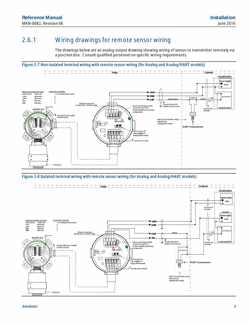
2.6.1 Wiring drawings for remote sensor wiring The drawings below are an analog output drawing showing wiring of sensor to transmitter remotely via a junction box. Consult qualified personnel on specific wiring requirements.
Figure 2-7 Non-isolated terminal wiring with remote sensor wiring (for Analog and Analog/HART models)
Figure 2-8 Isolated terminal wiring with remote sensor wiring (for Analog and Analog/HART models)

Installation Reference Manual June 2016 MAN-0082, Revision 08
10 Installation
2.7 Installation checklist Review the following checklist prior to turning the power on to the transmitter after installation has been completed:
□ Ensure that the transmitter and sensor are properly and firmly mounted.
□ Ensure that stopping plugs are securely tightened on any unused conduit entries.
□ Ensure that the transmitter and sensor are not obstructed; transmitter and sensor are accessible and target gas is not inhibited from reaching the sensor.
□ Ensure adherence to applicable local guidelines and requirements on wiring and sealing of equipment in hazardous and non-hazardous areas.
□ Ensure that proper shielding and grounding practices are adhered to and local codes are being followed.
□ Check system operational voltage and conditions; ensuring that they are within the applicable specifications of the transmitter and sensor.
□ Verify wiring at all termination and junction points (transmitter, junction box, and power supply).
□ Ensure that the transmitter housing cover and sensor cap are secured tightly.

Reference Manual Operation MAN-0082, Revision 08 June 2016
Operation 11
Section 3: Operation 3.1 Transmitter and faceplate description
After wiring is completed and power is applied, indicated by the green power LED, a warm-up routine will begin, where the sensor is automatically tested to ensure proper operation. The Status LED will slowly flash red and the current output will be 3.0 mA (indicated by Analog models). Once the warm-up routine has been completed, the LED will flash green, indicating normal operation. The time taken for the transmitter to complete its warm-up cycle is dependent on the type of sensor being used.
Figure 3-1 Faceplate description
The transmitter faceplate shows the position of the magnetic switch, the status LED, and the status LED states. See Section 7 for more information on the Status LED.
3.2 Intrusive access
Do not open the transmitter, sensor, or junction box enclosure when in a classified area or when an explosive atmosphere may be present unless the power to the transmitter has been removed.
This involves the removal of the top cover and faceplate to access the pushbutton switch when calibrating and resetting the transmitter. Pressing and holding the pushbutton down for up to three (3) seconds resets the transmitter; latched alarms are cleared and sensor performed self-tests. Holding down the pushbutton for up to fifteen (15) seconds sends the transmitter into full calibration mode. See Section 6 for more information on calibration and manual reset.
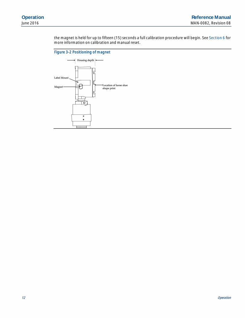
3.3 Non-intrusive access (magnetic Reed switch Access) This involves placing and holding the attached magnet next to the base of the label mount as indicated in Figure 3-2. When the magnet is held for up to three (3) seconds, a manual reset will be initiated. If
Operation Reference Manual June 2016 MAN-0082, Revision 08
12 Operation
the magnet is held for up to fifteen (15) seconds a full calibration procedure will begin. See Section 6 for more information on calibration and manual reset.
Figure 3-2 Positioning of magnet
Reference Manual Output configurations MAN-0082, Revision 08 June 2016
Output configurations 13
Section 4: Output configurations 4.1 Analog board assembly
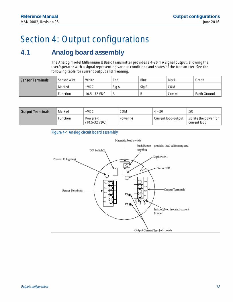
The Analog model Millennium II Basic Transmitter provides a 4-20 mA signal output, allowing the user/operator with a signal representing various conditions and states of the transmitter. See the following table for current output and meaning.
Sensor Terminals Sensor Wire White Red Blue Black Green
Marked +VDC Sig A Sig B COM
Function 10.5 - 32 VDC A B Comm Earth Ground
Output Terminals Marked +VDC COM 4 – 20 ISO
Function Power (+) (10.5-32 VDC)
Power (-) Current loop output Isolate the power for current loop
Figure 4-1 Analog circuit board assembly
Output configurations Reference Manual June 2016 MAN-0082, Revision 08
14 Output configurations
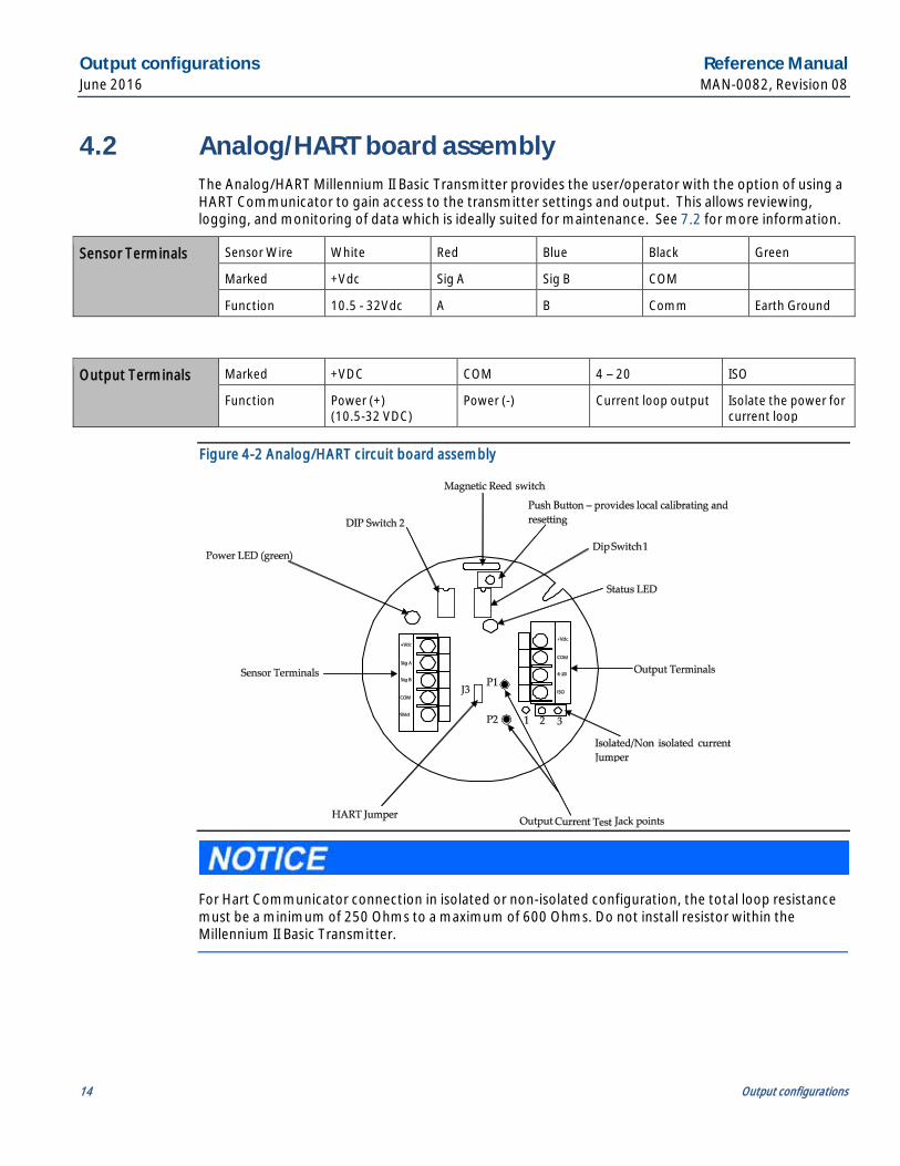
4.2 Analog/HART board assembly The Analog/HART Millennium II Basic Transmitter provides the user/operator with the option of using a HART Communicator to gain access to the transmitter settings and output. This allows reviewing, logging, and monitoring of data which is ideally suited for maintenance. See 7.2 for more information.
Sensor Terminals Sensor Wire White Red Blue Black Green
Marked +Vdc Sig A Sig B COM
Function 10.5 - 32Vdc A B Comm Earth Ground
Output Terminals Marked +VDC COM 4 – 20 ISO
Function Power (+) (10.5-32 VDC)
Power (-) Current loop output Isolate the power for current loop
Figure 4-2 Analog/HART circuit board assembly
For Hart Communicator connection in isolated or non-isolated configuration, the total loop resistance must be a minimum of 250 Ohms to a maximum of 600 Ohms. Do not install resistor within the Millennium II Basic Transmitter.

Reference Manual Output configurations MAN-0082, Revision 08 June 2016
Output configurations 15
4.3 Relay board assembly/configuration This assembly has three (3) relays; a fault alarm relay, a low alarm relay and a high alarm relay. The fault alarm relay is fixed as energized and non-latching and cannot be changed. The low alarm relay and the high alarm relay may be configured as energized or de-energized and latching or non-latching. By default the low and high alarm relay contacts are de-energized and non-latching. For more information on adjusting the relay settings refer to 7.3.
Sensor Terminals Sensor Wire White Red Blue Black Green
Marked +VDC Sig A Sig B COM
Function 10.5 - 32 VDC A B Comm Earth Ground
Output Terminals
Marked RST +VDC COM FNO FCOM FNC A1NO A1COM A1NC A2NO A2COM A2NC
Function Remote Reset
Power (+) (10.5-32 VDC)
Power (-)
Fault Alarm 1 (Low Alarm)
Alarm 2 (High Alarm)
Relay definitions:
Fault Alarm contacts: Fault Normally Open (FNO), Fault Common (FCOM), and Fault Normally Closed (FNC).
Low Alarm contacts: Alarm 1 Normally Open (A1NO), Alarm 1 Common (A1COM) and Alarm 1 Normally Closed (A1NC).
High Alarm contacts: Alarm 2 Normally Open (A2NO), Alarm 2 Common (A2COM) and Alarm 2 Normally Closed (A2NC).
Figure 4-3 Relay circuit board assembly
Output configurations Reference Manual June 2016 MAN-0082, Revision 08
16 Output configurations
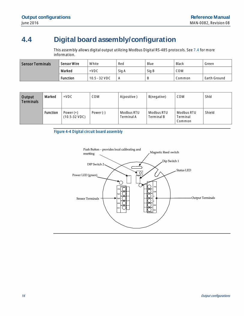
4.4 Digital board assembly/configuration This assembly allows digital output utilizing Modbus Digital RS-485 protocols. See 7.4 for more information.
Sensor Terminals Sensor Wire White Red Blue Black Green
Marked +VDC Sig A Sig B COM
Function 10.5 - 32 VDC A B Common Earth Ground
Output Terminals
Marked +VDC COM A(positive ) B(negative) COM Shld
Function Power (+) (10.5-32 VDC)
Power (-) Modbus RTU Terminal A
Modbus RTU Terminal B
Modbus RTU Terminal Common
Shield
Figure 4-4 Digital circuit board assembly

Reference Manual Operation MAN-0082, Revision 08 June 2016
Operation 17
Section 5: Operation 5.1 DIP switch settings
5.1.1 Infrared sensor (SC311) gas curve selection When using the SC311 sensor with the Millennium II Basic transmitter, DIP switch 2 on the transmitter should be set up as follows:
The gas curve or range should only be changed when the sensor and transmitter are in normal state. After powering up, the transmitter, the status LED will slowly flash green to indicate normal operating state. The system should be recalibrated with 50% of the specific target gas if the sensor’s range is changed.
Position 1 Position 2 Position 3 Position 4 Gas Curve
OFF OFF OFF OFF Methane (0)
ON OFF OFF OFF Propane (1)*
OFF ON OFF OFF n-Butane (2)*
ON ON OFF OFF Iso-Pentane (3)*
OFF OFF ON OFF n-Pentane (4)*
ON OFF ON OFF Ethane (5)
OFF ON ON OFF Iso-Butane (6)*
ON ON ON OFF Ethylene (7)
OFF OFF OFF ON Hexane (8)*
ON OFF OFF ON Propylene (9)*
*Indicates gases are not third party performance verified
5.1.2 Hydrogen sulfide sensor (ST320) range selection Position 1 Position 2 Position 3 Position 4 Range(Setting)
ON OFF OFF OFF Range 1 (20ppm)
OFF ON OFF OFF Range 2 (50ppm)
OFF OFF ON OFF Range 3 (100ppm)
Operation Reference Manual June 2016 MAN-0082, Revision 08
18 Operation
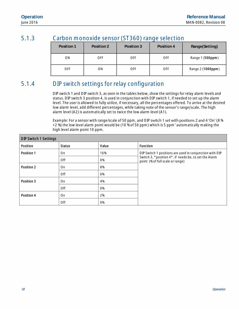
5.1.3 Carbon monoxide sensor (ST360) range selection Position 1 Position 2 Position 3 Position 4 Range(Setting)
ON OFF OFF OFF Range 1 (500ppm)
OFF ON OFF OFF Range 2 (1000ppm)
5.1.4 DIP switch settings for relay configuration DIP switch 1 and DIP switch 3, as seen in the tables below, show the settings for relay alarm levels and status. DIP switch 3 position 4, is used in conjunction with DIP switch 1, if needed to set up the alarm level. The user is allowed to fully utilize, if necessary, all the percentages offered. To arrive at the desired low alarm level, add different percentages, while taking note of the sensor’s range/scale. The high alarm level (A2) is automatically set to twice the low alarm level (A1).
Example: For a sensor with range/scale of 50 ppm, and DIP switch 1 set with positions 2 and 4 ‘On’ (8 % +2 %) the low level alarm point would be (10 % of 50 ppm) which is 5 ppm’ automatically making the high level alarm point 10 ppm.
DIP Switch 1 Settings
Position Status Value Function
Position 1 On 16% DIP Switch 1 positions are used in conjunction with DIP Switch 3, *position 4*, if needs be, to set the Alarm point (% of full scale or range) Off 0%
Position 2 On 8%
Off 0%
Position 3 On 4%
Off 0%
Position 4 On 2%
Off 0%
Reference Manual Operation MAN-0082, Revision 08 June 2016
Operation 19
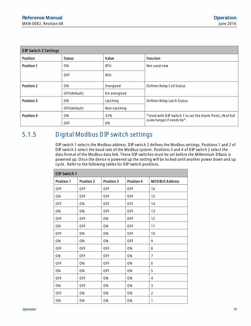
DIP Switch 3 Settings
Position Status Value Function
Position 1 ON RFU Not used now
OFF RFU
Position 2 ON Energized Defines Relay Coil Status
OFF(default) De-energized
Position 3 ON Latching Defines Relay Latch Status
OFF(default) Non-Latching
Position 4 ON 32% *Used with DIP Switch 1 to set the Alarm Point, (% of full scale/range) if needs be*.
OFF 0%
5.1.5 Digital Modbus DIP switch settings DIP switch 1 selects the Modbus address. DIP switch 2 defines the Modbus settings. Positions 1 and 2 of DIP switch 2 select the baud rate of the Modbus system. Positions 3 and 4 of DIP switch 2 select the data format of the Modbus data link. These DIP switches must be set before the Millennium II Basic is powered up. Once the device is powered up the setting will be locked until another power down and up cycle. Refer to the following tables for DIP switch positions.
DIP Switch 1
Position 1 Position 2 Position 3 Position 4 MODBUS Address
OFF OFF OFF OFF 16
ON OFF OFF OFF 15
OFF ON OFF OFF 14
ON ON OFF OFF 13
OFF OFF ON OFF 12
ON OFF ON OFF 11
OFF ON ON OFF 10
ON ON ON OFF 9
OFF OFF OFF ON 8
ON OFF OFF ON 7
OFF ON OFF ON 6
ON ON OFF ON 5
OFF OFF ON ON 4
ON OFF ON ON 3
OFF ON ON ON 2
ON ON ON ON 1
Operation Reference Manual June 2016 MAN-0082, Revision 08
20 Operation
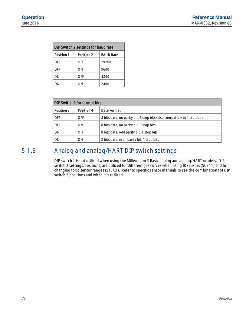
DIP Switch 2 settings for baud rate
Position 1 Position 2 BAUD Rate
OFF OFF 19200
OFF ON 9600
ON OFF 4800
ON ON 2400
DIP Switch 2 for format bits
Position 3 Position 4 Date Format
OFF OFF 8 bits data, no parity bit, 2 stop bits (also compatible to 1 stop bit)
OFF ON 8 bits data, no parity bit, 2 stop bits
ON OFF 8 bits data, odd parity bit, 1 stop bits
ON ON 8 bits data, even parity bit, 1 stop bits
5.1.6 Analog and analog/HART DIP switch settings DIP switch 1 is not utilized when using the Millennium II Basic analog and analog/HART models. DIP switch 2 settings/positions, are utilized for different gas curves when using IR sensors (SC311) and for changing toxic sensor ranges (ST3XX). Refer to specific sensor manuals to see the combinations of DIP switch 2 positions and when it is utilized.

Reference Manual Calibration procedure MAN-0082, Revision 08 June 2016
Calibration procedure 21
Section 6: Calibration procedure 6.1 Calibration procedure
Prior to attempting calibration read and understand the calibration procedure below. Also see Figure 6-1 for additional reference.
The following calibration procedure should be followed to ensure an accurate correlation between the output signals and the gas concentration. For accurate performance, the Millennium II Basic Transmitter is calibrated using 50% span gas.
6.1.1 Guidelines Calibration is recommended after the Millennium II Basic and sensor are installed. Calibration should be performed after the sensor has been powered for at least 24 hours. Refer to specific sensor manuals for details on calibrating.
All systems should be bypassed during calibration and bump testing to avoid unwanted alarms.
6.1.2 Full calibration procedure 1. Confirm successful power-up of transmitter, (green or red flashing of status LED).
2. For analog model connect a standard ammeter to the transmitter Test Jacks (not required but gives visual confirmation). See figures in Section 4 for Test Jacks location.
3. Press and hold the pushbutton, or activate the Reed switch using the magnet, for at least fifteen (15) seconds; the status LED flashes green fast, and then goes solid green (first solid green), keep holding the pushbutton or magnet, after which, the status LED goes solid red. Release the pushbutton or remove magnet.
4. When the current output is 3 mA (indicated by analog models) and the status LED is once again solid green (second solid green). Apply zero gas (clean air). Recommendation: Flow clean air at a rate of 0.5 liter per minute or more to the sensor for best results.
5. When the current output is 3.3 mA (indicated by analog models) and the status LED is flashing red, apply the calibration gas (50% of full span) to the sensor. Recommendation: Flow span gas at a rate of 0.5 liter per minute to the sensor for direct sensor calibration. If the sensor is separated with long tubing runs, increase the gas flow rate to ensure tubing does not affect calibration results.
6. When the current output is 3.6 mA (indicated by analog models) and the status LED is solid green, remove the calibration gas.
7. Apply zero gas (clean air) again to purge the system if calibration tubing is used.
8. After the sensor is purged of gas, the transmitter will return to normal operation.

Calibration procedure Reference Manual June 2016 MAN-0082, Revision 08
22 Calibration procedure
6.2 Zeroing procedure This option is useful if the sensor’s zero point has drifted as a result of a change in the ambient conditions.
Zeroing does not require the application of a calibration gas. It does, however, require that no contaminated gas is present in the ambient air, if the surrounding air is being used.
Zeroing is not a substitute for performing a full calibration. Zeroing can be completed on an interim basis; however, It is highly recommended that a full calibration be completed whenever possible.
1. Confirm successful power-up of transmitter, (green flashing of status LED every second: no fault indicated).
2. For analog model connect a standard ammeter to the transmitter Test Jacks (not required but gives visual confirmation). See figures in Section 4 for Test Jacks location.
3. Press and hold the pushbutton, or activate the Reed switch using the magnet, until the status LED flashes green fast, and then goes solid green. Release the pushbutton or deactivate the Reed switch.
4. When the status LED is solid green, the current output will be 3 mA (indicated by analog models). Apply zero gas (clean air). Recommendation: Flow clean air at a rate of 0.5 liter per minute or more to the sensor.
5. Zeroing is complete when the current output is 3.6 mA (indicated by analog models) after which, the Status LED flashes green every second (current output of 4 mA). Remove the zero gas, or allow the transmitter to return to normal operation if ambient (clean surrounding) air was used.
6. Normal operation is confirmed by a current output of 4 mA (indicated by analog models) and the status LED flashing green every second.
Reference Manual Calibration procedure MAN-0082, Revision 08 June 2016
Calibration procedure 23
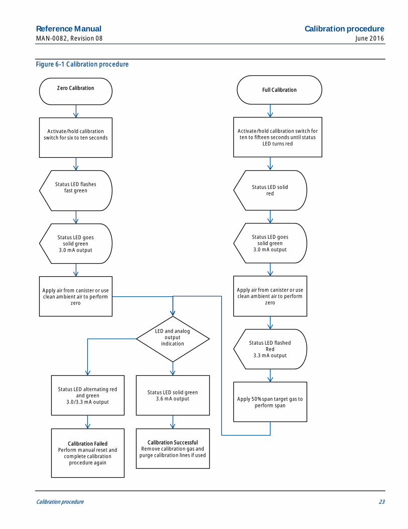
Figure 6-1 Calibration procedure
Full Calibration
Activate/hold calibration switch for six to ten seconds
LED and analog output
indication
Status LED solid green 3.6 mA output
Zero Calibration
Status LED flashes fast green
Status LED goes solid green
3.0 mA output
Apply air from canister or use clean ambient air to perform
zero
Activate/hold calibration switch for ten to fifteen seconds until status
LED turns red
Status LED solid red
Status LED goes solid green
3.0 mA output
Apply air from canister or use clean ambient air to perform
zero
Status LED flashed Red
3.3 mA output
Apply 50% span target gas to perform span
Calibration Successful Remove calibration gas and
purge calibration lines if used
Status LED alternating red and green
3.0/3.3 mA output
Calibration Failed Perform manual reset and
complete calibration procedure again
Calibration procedure Reference Manual June 2016 MAN-0082, Revision 08
24 Calibration procedure
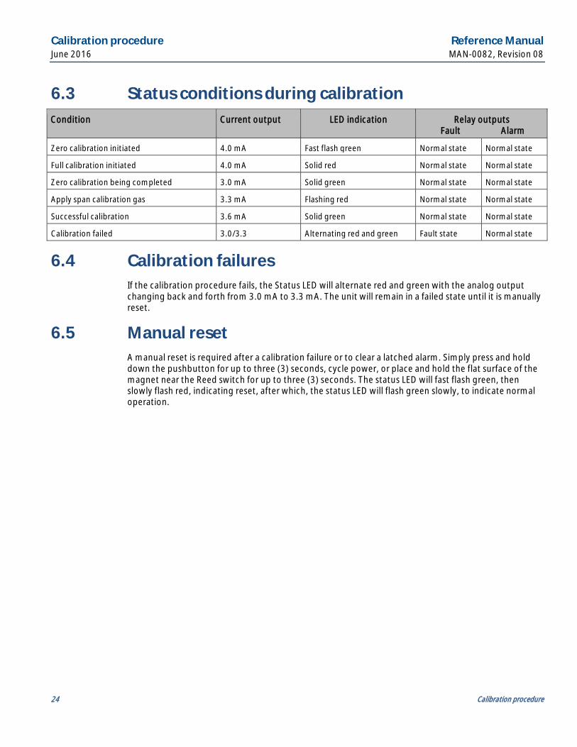
6.3 Status conditions during calibration Condition Current output LED indication Relay outputs
Fault Alarm
Zero calibration initiated 4.0 mA Fast flash green Normal state Normal state
Full calibration initiated 4.0 mA Solid red Normal state Normal state
Zero calibration being completed 3.0 mA Solid green Normal state Normal state
Apply span calibration gas 3.3 mA Flashing red Normal state Normal state
Successful calibration 3.6 mA Solid green Normal state Normal state
Calibration failed 3.0/3.3 Alternating red and green Fault state Normal state
6.4 Calibration failures If the calibration procedure fails, the Status LED will alternate red and green with the analog output changing back and forth from 3.0 mA to 3.3 mA. The unit will remain in a failed state until it is manually reset.
6.5 Manual reset A manual reset is required after a calibration failure or to clear a latched alarm. Simply press and hold down the pushbutton for up to three (3) seconds, cycle power, or place and hold the flat surface of the magnet near the Reed switch for up to three (3) seconds. The status LED will fast flash green, then slowly flash red, indicating reset, after which, the status LED will flash green slowly, to indicate normal operation.

Reference Manual Monitoring and outputs MAN-0082, Revision 08 June 2016
Monitoring and outputs 25
Section 7: Monitoring and outputs 7.1 Analog 4-20mA
The Millennium II Basic transmitters (with the exception of the M2B-R) offer a variable 4-20 mA analog output. This output will provide gas concentration through the 4-20 mA range, where 4 mA equals zero gas concentration and 20 mA equals the high range of the sensor (e.g. 100% LEL or 100 ppm). Other conditions such as faults and calibration notifications (e.g. apply gas) are indicated in the 0-3.9 mA range. Faults are indicated at either 0 mA or 2.5 mA.
7.2 HART Communication (Optional) The HART protocol is a powerful communication technology enabling users to exploit the full functionality of the Millennium II Basic Transmitter.
The HART Communicator may be connected to the Analog/HART model Millennium II Basic Transmitter via the HART Port connector (HPT-001) which provides the necessary interface for communication on the analog output wires. The HART Port connector is fitted to one of the ¾” NPT conduit entries and its communication wires fitted to the HART Pins located at J3 on the Analog/HART PCB. The HART Communicator probe wires (leads) are then connected to HART Port connector contact points.
When remote HART Communication is being completed, ensure the HART Jumper is connected across pins at J3. See Figure 4-2 for the location of J3. By default the jumper is connected across the pins.
When the system is powered-up, the communicator will search for the Millennium II Basic Transmitter and when a connection is established, the communicator will show the device information. If the Millennium II Basic Transmitter Device Description (DD) is loaded into the communicator, the communicator can access all the information and features of the Millennium II Basic Transmitter. If the communicator is not programmed with the specific DD, the Millennium II Basic Transmitter can still work with the communicator as a generic device.
7.2.1 HART Menu Structure The Hart Menu structure exists when using the HART Communicator and allows the user to see all existing options, Device status, Calibration information and History. Refer to Figure 7-1 and Figure 7-2 for the HART menu structure and tree.
Monitoring and outputs Reference Manual June 2016 MAN-0082, Revision 08
26 Monitoring and outputs
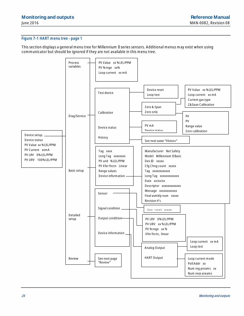
Figure 7-1 HART menu tree - page 1
This section displays a general menu tree for Millennium II series sensors. Additional menus may exist when using communicator but should be ignored if they are not available in this menu tree.
Process variables Diag/Service Basic setup Detailed setup Review
Device setup. Device status PV Value xx % LEL/PPM PV Current xxmA PV LRV 0% LEL/PPM PV URV 100% LEL/PPM
PV Value xx % LEL/PPM PV % rnge xx% Loop current xx mA
Test device Calibration Device status History
Tag xxxx Long Tag xxxxxxxx PV unit % LEL/PPM PV Xfer fnctn Linear Range values Device information
Sensor Signal condition Output condition Device information
See next page “Review”
Device reset Loop test
Zero & Span Zero only
PV Value xx % LEL/PPM Loop current xx mA Current gas type Z&Span Calibration
PV mA Device status
See next page “History”
Manufacturer Net Safety Model Millennium II Basic Dev ID xxxxx Cfg Chng count xxxxx Tag xxxxxxxxxxxx Long Tag xxxxxxxxxxxxx Date xx/xx/xx Descriptor xxxxxxxxxxxxx Message xxxxxxxxxxxx Final asmbly num xxxxx Revision #’s
See next page
PV LRV 0% LEL/PPM PV URV xx % LEL/PPM PV % rnge xx % Xfer fnctn, linear
Analog Output HART Output
Loop current xx mA Loop test
Loop current mode Poll Addr xx Num reg preams xx Num resp preams
PV PV Range value Zero calibration

Reference Manual Monitoring and outputs MAN-0082, Revision 08 June 2016
Monitoring and outputs 27
Figure 7-2 HART menu tree - page 2
“History”
“Sensor”
“Review”
Catalytic Bead Sensor, IR combustible, H2S toxic
PV xx % LEL PV Unit % LEL Sensor
Max Temperature Min Temperature Calibration Log
Max Temperature xxx Deg C Max Temperature Since Reset xx Deg C Reset Date xx/xx/xxxx Reset Time xxxx Reset Max Min Temperature
Min Temperature xxx Deg C Min Temperature Since Reset xx Deg C Reset Date xx/xx/xxxx Reset Time xxxx Reset Max Min Temperature
Calibration Date xx/xx/xxxx Calibration Time xxxx Cal Event Type xxxxxxxxx Next Log Previous Log Most Recent Log
Sensor Class Cat Bead Combustible, Infrared Combustible, H2S toxic, CO toxic Sensor Temperature xxx Deg C Sensor Remain Time xxxx Days Current gas type PV LSL 0% LEL/PPM PV USL 100% LEL/PPM PV Min span 1% LEL/PPM Gas type and range
Manufacturer Net Safety Model Millennium II Basic Dev ID xxxxxx Tag xxxxxxxxxxx Long Tag xxxxxxxxxxxxxx Descriptor xxxxxxxxxxxxxx Message xxxxxxxxxxxxxx Date xx/xx/xx Final asmbly num xxxxxxx Universal rev 7 Fld dev rev xx Software rev xx Poll addr xx Loop current mode Disabled/Enabled Num reg preams xx Num resp preams xx
Current gas type Custom K factor PV U SL Support gas type Support USL(range)
Sensor gas 1 Sensor gas 2 Sensor gas 3……….16
Sensor range 1 Sensor range 2 Sensor range 3…….5
Monitoring and outputs Reference Manual June 2016 MAN-0082, Revision 08
28 Monitoring and outputs
7.3 Relays (Optional)
7.3.1 Alarm relays The Millennium II Basic transmitters come complete with two (2) programmable alarm relays. These relays will change their state from their non-alarm state to an alarm state when gas concentrations, as read by the sensor, go above the programmed alarm points set in the transmitter.
The alarm relays can be programmed to be energized or de-energized under normal conditions, and then either latching or non-latching.
7.3.2 Fault relay Millennium II Basic transmitters and sensors complete continual checks for situations that may prevent the transmitter and sensor from providing an expected response to ambient conditions and records these as a fault condition in the message log and the output(s) of the transmitter. When a system fault is detected, the Red Status LED will flash fast (250 milliseconds on, 250 milliseconds off), the analog output will output a 2.5 mA signal, and the fault relay will change states (de-energize to provide a fault condition).
The fault relay is normally energized when no fault conditions are present and is set up for non-latching. The operation of the fault relay is not configurable.
The Millennium II Basic transmitter provides various fault conditions to indicate that the transmitter or connected sensor(s) are not operating as expected. These fault conditions will override any alarm conditions because the sensor may be unable to detect a gas exposure reliably. Examples of fault conditions can range from no detection due to memory or communication errors and sensor failure. Other faults can provide unreliable detection due to sensor drift or sensor nearing the end of its life. When a Millennium II Basic transmitter is in fault mode, immediate action should be taken to determine the source and correct the fault condition.
The fault relay output is not commonly used to imitate an automatic shutdown. The fault output indicates a potential problem with the transmitter not an alarm condition.
7.4 RS-485 Modbus RTU (Optional) Modbus digital RS-485 Modbus RTU protocol is used.
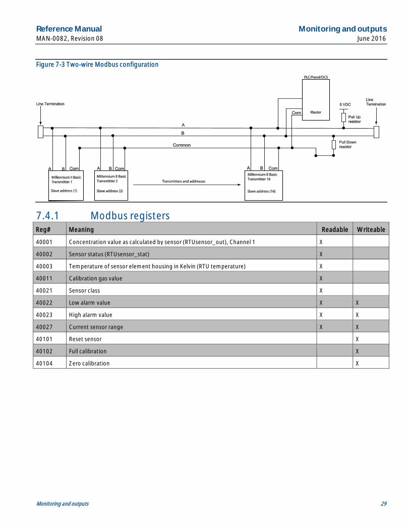
The Millennium II Basic transmitter utilizes 2- wire Modbus RS-485 multi serial mode. This Modbus solution implements a 2-wire electrical interface in accordance with the EIA/TIA-485 standards. For this Modbus configuration, it is important that a third wire be used for connecting all the commons (COM) in the chain. Also a 120 Ohm line termination is required for the last device in the line. See Figure 7-3. The Instrument Engineer is responsible for calculating line length and adhering to Modbus protocols.
Reference Manual Monitoring and outputs MAN-0082, Revision 08 June 2016
Monitoring and outputs 29
Figure 7-3 Two-wire Modbus configuration
7.4.1 Modbus registers Reg# Meaning Readable Writeable
40001 Concentration value as calculated by sensor (RTUsensor_out), Channel 1 X
40002 Sensor status (RTUsensor_stat) X
40003 Temperature of sensor element housing in Kelvin (RTU temperature) X
40011 Calibration gas value X
40021 Sensor class X
40022 Low alarm value X X
40023 High alarm value X X
40027 Current sensor range X X
40101 Reset sensor X
40102 Full calibration X
40104 Zero calibration X
Monitoring and outputs Reference Manual June 2016 MAN-0082, Revision 08
30 Monitoring and outputs
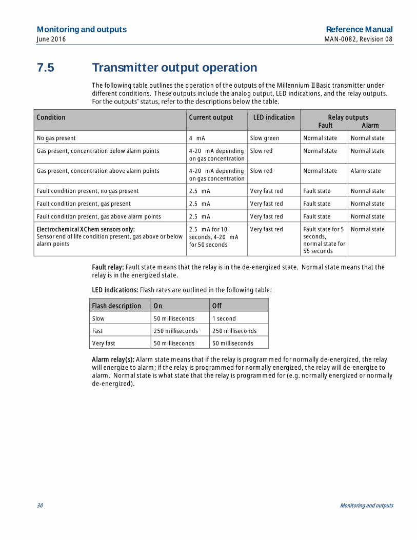
7.5 Transmitter output operation The following table outlines the operation of the outputs of the Millennium II Basic transmitter under different conditions. These outputs include the analog output, LED indications, and the relay outputs. For the outputs’ status, refer to the descriptions below the table.
Condition Current output LED indication Relay outputs Fault Alarm
No gas present 4 mA Slow green Normal state Normal state
Gas present, concentration below alarm points 4-20 mA depending on gas concentration
Slow red Normal state Normal state
Gas present, concentration above alarm points 4-20 mA depending on gas concentration
Slow red Normal state Alarm state
Fault condition present, no gas present 2.5 mA Very fast red Fault state Normal state
Fault condition present, gas present 2.5 mA Very fast red Fault state Normal state
Fault condition present, gas above alarm points 2.5 mA Very fast red Fault state Normal state
Electrochemical XChem sensors only: Sensor end of life condition present, gas above or below alarm points
2.5 mA for 10 seconds, 4-20 mA for 50 seconds
Very fast red Fault state for 5 seconds, normal state for 55 seconds
Normal state
Fault relay: Fault state means that the relay is in the de-energized state. Normal state means that the relay is in the energized state.
LED indications: Flash rates are outlined in the following table:
Flash description On Off
Slow 50 milliseconds 1 second
Fast 250 milliseconds 250 milliseconds
Very fast 50 milliseconds 50 milliseconds
Alarm relay(s): Alarm state means that if the relay is programmed for normally de-energized, the relay will energize to alarm; if the relay is programmed for normally energized, the relay will de-energize to alarm. Normal state is what state that the relay is programmed for (e.g. normally energized or normally de-energized).

Reference Manual Monitoring and outputs MAN-0082, Revision 08 June 2016
Monitoring and outputs 31
7.6 Fault monitoring Self-testing circuitry continuously checks for problems that could prevent proper response. When power is applied to the Millennium II Basic Transmitter, a microcontroller automatically tests the system to ensure that it is functioning properly. During normal operation, it continuously monitors the signal from the internal sensor source. In addition, a watchdog timer is maintained to ensure the program is running correctly. When a system fault is detected, the Status LED will have a red fast flash and the fault signal will output a 2.5 mA signal. The transmitter’s event log may be viewed in order to distinguish the fault condition.
The fault detection circuitry does not monitor the operation of external response equipment or external wiring to the transmitter. It is important that external equipment and wiring be checked periodically to ensure they are operational.
7.7 Fault conditions
Fault conditions will override any alarm conditions because the sensor may be unable to detect a gas exposure reliably, as such, the alarm relay will not provide an output.
Fault conditions provided by an instrumentation device are critical indicators that the device is not operating as expected; therefore, when a fault condition is present, immediate attention to that fault condition is required.
Net Safety strongly recommends that the 2.5 mA analog fault condition and fault relay (if used) be monitored in conjunction with alarm levels on the analog output and the alarm relay, if used.
7.7.1 Transmitter fault conditions Fault conditions that the transmitter detects are as follows:
Fault condition M2B
Input voltage less than 8 VDC P
Input voltage more than 33 VDC P
Critical memory fault P
Onboard power supply fault P
Monitoring and outputs Reference Manual June 2016 MAN-0082, Revision 08
32 Monitoring and outputs
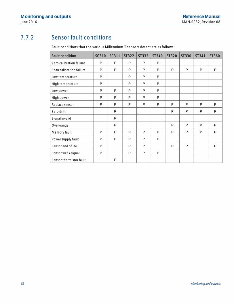
7.7.2 Sensor fault conditions Fault conditions that the various Millennium II sensors detect are as follows:
Fault condition SC310 SC311 ST322 ST332 ST340 ST320 ST330 ST341 ST360
Zero calibration failure P P P P P
Span calibration failure P P P P P P P P P
Low temperature P P P P
High temperature P P P P
Low power P P P P P
High power P P P P P
Replace sensor P P P P P P P P P
Zero drift P P P P P
Signal invalid P
Over-range P P P P P
Memory fault P P P P P P P P P
Power supply fault P P P P P
Sensor end of life P P P P P P
Sensor weak signal P P P P
Sensor thermistor fault P
Reference Manual Maintenance MAN-0082, Revision 08 June 2016
Maintenance 33
Section 8: Maintenance 8.1 Periodic response check
Net Safety Monitoring recommends that a bump test be performed every ninety (90) days to ensure continued functionality and accuracy of the detection system. Full calibration is recommended when the sensor fails to meet acceptable accuracy standards. This involves the application of calibration gas to the sensor, then the observation of the response LEDs, analog output, and external monitoring equipment. Be sure to prevent unwanted response of external monitoring devices and equipment during this procedure. If the Millennium II Basic’s response to calibration gas is within the specified accuracy then it is not necessary to perform a calibration.
Example: When 50% of full scale is applied, the response is expected to be between 11.5 mA (47% of full scale) and 12.5 mA (53% of full scale). An additional consideration is the accuracy tolerance of the calibration gas which may be plus or minus a few percent. If the calibration gas is ±10% of full scale then the reading may be from 10.7 mA (42% of full scale) to 13.3 mA (58% of full scale).
8.2 Troubleshooting Response to the input should be checked and, if necessary, calibration should be performed whenever the accuracy of this check is not satisfactory. The system should also be checked when sensor or transmitter is added or removed. If problems should develop, first check for faulty wiring, confirm proper voltage to transmitter and attempt a calibration. If problems persist, please contact Net Safety’s support department first by phone to try and resolve any issues. If issues cannot be resolved, please follow the procedure on how to return equipment.
8.3 Storage The transmitter and its electronic components/parts should be stored in locations free from dust and moisture. The storage temperature should be well within the limits of the certified temperatures of the equipment. See Section 11 for storage temperatures.
Maintenance Reference Manual June 2016 MAN-0082, Revision 08
34 Maintenance
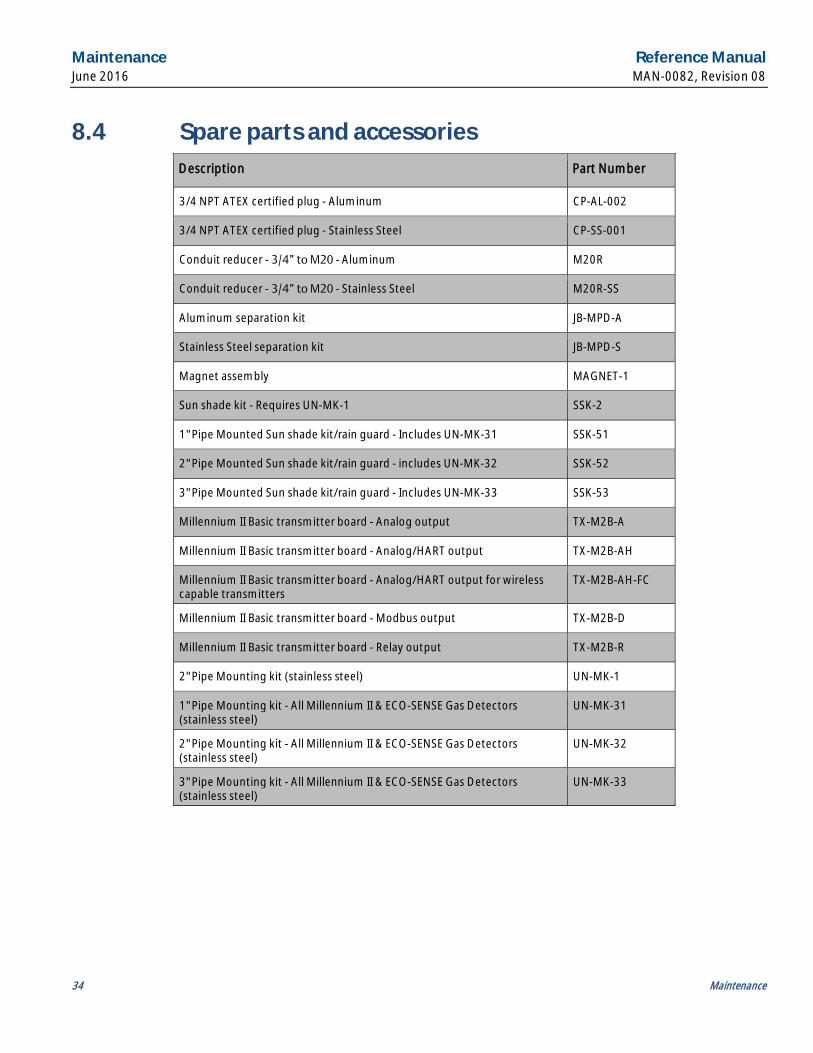
8.4 Spare parts and accessories Description Part Number
3/4 NPT ATEX certified plug - Aluminum CP-AL-002
3/4 NPT ATEX certified plug - Stainless Steel CP-SS-001
Conduit reducer - 3/4” to M20 - Aluminum M20R
Conduit reducer - 3/4” to M20 - Stainless Steel M20R-SS
Aluminum separation kit JB-MPD-A
Stainless Steel separation kit JB-MPD-S
Magnet assembly MAGNET-1
Sun shade kit - Requires UN-MK-1 SSK-2
1" Pipe Mounted Sun shade kit/rain guard - Includes UN-MK-31 SSK-51
2" Pipe Mounted Sun shade kit/rain guard - includes UN-MK-32 SSK-52
3" Pipe Mounted Sun shade kit/rain guard - Includes UN-MK-33 SSK-53
Millennium II Basic transmitter board - Analog output TX-M2B-A
Millennium II Basic transmitter board - Analog/HART output TX-M2B-AH
Millennium II Basic transmitter board - Analog/HART output for wireless capable transmitters
TX-M2B-AH-FC
Millennium II Basic transmitter board - Modbus output TX-M2B-D
Millennium II Basic transmitter board - Relay output TX-M2B-R
2" Pipe Mounting kit (stainless steel) UN-MK-1
1" Pipe Mounting kit - All Millennium II & ECO-SENSE Gas Detectors (stainless steel)
UN-MK-31
2" Pipe Mounting kit - All Millennium II & ECO-SENSE Gas Detectors (stainless steel)
UN-MK-32
3" Pipe Mounting kit - All Millennium II & ECO-SENSE Gas Detectors (stainless steel)
UN-MK-33

Reference Manual Electrostatic sensitive device MAN-0082, Revision 08 June 2016
Electrostatic sensitive device 35
Section 9: Electrostatic sensitive device Definition: Electrostatic discharge (ESD) is the transfer, between bodies, of an electrostatic charge caused by direct contact or induced by an electrostatic field.
The most common cause of ESD is physical contact. Touching an object can cause a discharge of electrostatic energy. If the charge is sufficient and occurs near electronic components, it can damage or destroy those components. In some cases, damage is instantaneous and an immediate malfunction occurs. However, symptoms are not always immediate—performance may be marginal or seemingly normal for an indefinite period of time, followed by a sudden failure.
To eliminate potential ESD damage, review the following guidelines:
· Handle boards by the sides —taking care not to touch electronic components.
· Wear grounded wrist or foot straps, ESD shoes or heel grounders to dissipate unwanted static energy.
· Prior to handling boards, dispel any charge in your body or equipment by touching a grounded metal surface.
· Ensure all components are transported and stored in ESD safe packaging.
· When returning boards, carefully package in the original carton and static protective wrapping.
· Ensure ALL personnel are educated and trained in ESD Control Procedures.
In general, exercise accepted and proven precautions normally observed when handling electrostatic sensitive devices.

Wire resistance table Reference Manual June 2016 MAN-0082, Revision 08
36 Wire resistance table
Section 10: Wire resistance table Distance Feet (Meters)
AWG #20 0.5 mm2
AWG #18 0.8 mm2
AWG #16 1.0 mm2
AWG #14 2.0 mm2
100 (30.5) 1.02 0.64 0.40 0.25
200 (61) 2.03 1.28 0.80 0.51
300 (91.4) 3.05 1.92 1.20 0.76
400 (121.9) 4.06 2.55 1.61 1.01
500 (152.4) 5.08 3.20 2.01 1.26
600 (182.9) 6.09 3.83 2.41 1.52
700 (213.4) 7.11 4.47 2.81 1.77
800 (243.8) 8.12 5.11 3.21 2.02
900 (274.3) 9.14 5.75 3.61 2.27
1000 (304.8) 10.20 6.39 4.02 2.53
1250 (381) 12.70 7.99 5.03 3.16
1500 (457.2) 15.20 9.58 6.02 3.79
1750 (533.4) 17.80 11.20 7.03 4.42
2000 (609.6) 20.30 12.80 8.03 5.05
2250 (685.8) 22.80 14.40 9.03 5.68
2500 (762) 25.40 16.00 10.00 6.31
3000 (914.4) 30.50 19.20 12.00 7.58
3500 (1066.8) 35.50 22.40 14.10 8.84
4000 (1219.2) 40.60 25.50 16.10 10.00
4500 (1371.6) 45.70 28.70 18.10 11.40
5000 (1524) 50.10 32.00 20.10 12.60
5500 (1676.4) 55.80 35.10 22.10 13.91
6000 (1828.8) 61.00 38.30 24.10 15.20
6500 (1981.2) 66.00 41.50 26.10 16.40
7000 (2133.6) 71.10 44.70 28.10 17.70
7500 (2286) 76.10 47.90 30.10 19.00
8000 (2438.4) 81.20 51.10 23.10 20.20
9000 (2743.2) 91.40 57.50 36.10 22.70
10000 (3048) 102.00 63.90 40.20 25.30
Resistance shown is one way. This figure must be doubled when determining closed loop resistance.

Reference Manual Specifications MAN-0082, Revision 08 June 2016
Specifications 37
Section 11: Specifications 11.1 Electrical
11.1.1 Operating voltage range 10.5 to 32 VDC
18 to 32 VDC (HART versions only)
11.1.2 Power consumption 1.5 W @ 24 VDC (average - varies by sensor types/quantities)
11.1.3 EMC compliance EN 50270:2006 per EMC directive 2004/108/EC
11.2 Environmental
11.2.1 Operating temperature -67 °F to +185 °F (-55 °C to +85 °C ) -58 °F to +185 °F (-50 °C to +85 °C) – North American explosion-proof certification
11.2.2 Relative humidity 0 - 95% RH non-condensing
11.2.3 Ingress protection IP67 Type 4X
11.3 Mechanical
11.3.1 Enclosure material Cast Aluminum (6061) Stainless steel (SS316)
11.3.2 Conduit opening 3/4” NPT (3X)
11.3.3 Weight Aluminum: 2.0 lbs (0.8 kg) Stainless Steel: 3.5 lbs (1.6 kg)

Specifications Reference Manual June 2016 MAN-0082, Revision 08
38 Specifications
11.4 Warranty 3 years

Reference Manual Certifications MAN-0082, Revision 08 June 2016
Certifications 39
Section 12: Certifications 12.1 North American
Class I, Division 1, Groups BCD T5 Class I, Zone 1, AEx/Ex d IIB+ H2 T5 -50°C ≤ Ta ≤ + 85°C NEMA Type 4X/IP 67 FM6320, ANSI/ISA 12.13.01, CSA C22.2 No. 152:2006
12.2 IECEx Ex d IIB+H2 T5 Gb -55°C ≤ Ta ≤ + 85°C IP67 IEC 60079-0:2011/IEC60079-1:2007 IECEx FMG 14.0010X
12.3 FC Models
12.3.1 North America Class I, Division 1, Groups BCD T5 Class I, Zone 1, AEx/Ex d IIB+ H2 T5 -50 °C ≤ Ta ≤ +85 °C NEMA Type 4X/IP67 CSA C22.2 No. 152:2006
12.3.2 IECEx Ex d IIB+H2 T5 Gb -55°C ≤ Ta + 85°C IP67 IEC 60079-0:2011/IEC60079-1:2007 IECEx FMG 14.0010X
Special conditions for safe use:
· Consult the manufacturer if dimensional information on the flameproof joints is necessary.
· Follow the manufacturer’s instructions to reduce the potential of an electrostatic charging hazard.
Ordering information Reference Manual June 2016 MAN-0082, Revision 08
40 Ordering information
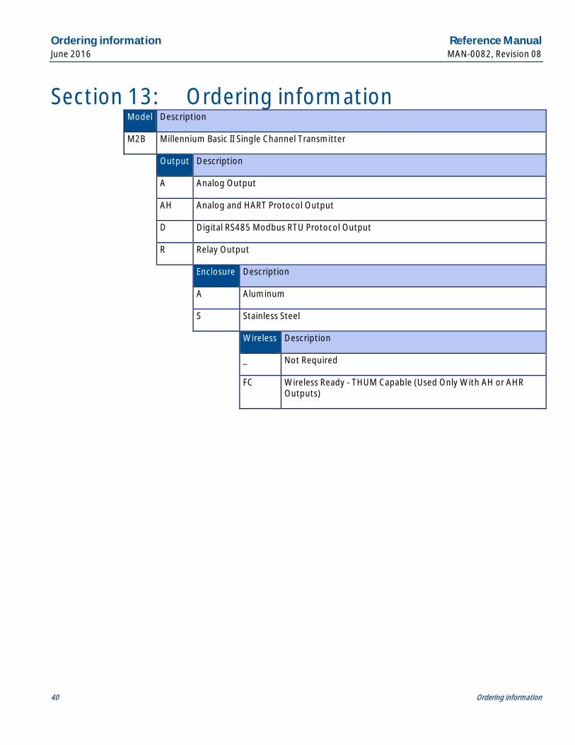
Section 13: Ordering information Model Description
M2B Millennium Basic II Single Channel Transmitter
Output Description
A Analog Output
AH Analog and HART Protocol Output
D Digital RS485 Modbus RTU Protocol Output
R Relay Output
Enclosure Description
A Aluminum
S Stainless Steel
Wireless Description
_ Not Required
FC Wireless Ready - THUM Capable (Used Only With AH or AHR
Outputs)

Notes

Notes

Notes

MAN-0082 Revision 08
June 2016
EmersonProcess.com/FlameGasDetection
AnalyticExpert.com twitter.com/Rosemount_News
youtube.com/user/RosemountMeasurement facebook.com/Rosemount
Americas Emerson Process Management 6021 Innovation Blvd. Shakopee, MN 55379 USA T +952 906 8888 F +952 949 7001 [email protected]
Europe Emerson Process Management AG Neuhofstrasse 19a P.O. Box 1046 CH-6340 Baar Switzerland T + 41 (0) 41 768 6111 F +41 (0) 41 768 6300 [email protected]
Middle East and Africa Emerson Process Management Emerson FZE Jebel Ali Free Zone Dubai, UAE P.O. Box 17033 T +971 4 811 8100 F + 971 4 886 5465 [email protected]
Asia Pacific Emerson Process Management Asia Pacific Private Limited 1 Pandan Crescent Singapore 128461 Republic of Singapore T + 65 6 777 8211 F + 65 6 777 0947 [email protected]
©2016 Emerson Process Management. All rights reserved.
The Emerson logo is a trademark and service mark of Emerson Electric Co. Rosemount is a mark of one of the Emerson Process Management family of companies. All other marks are property of their respective owners.
The contents of this publication are presented for information purposes only, and, while effort has been made to ensure their accuracy, they are not to be construed as warranties or guarantees, express or implied, regarding the products or services described herein or their use or applicability. All sales are governed by our terms and conditions, which are available on request. We reserve the right to modify or improve the designs or specifications of our products at any time without notice.