miller-ota opamp design in amis cmos 07 by roman prokop
TRANSCRIPT

Miller-OTA Opamp design
In AMIS CMOS 07
by Roman Prokop
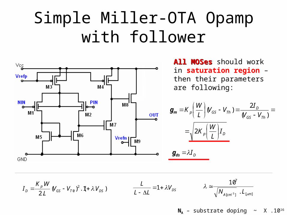
Simple Miller-OTA Opampwith follower
).1.()(.2
. 20 DSTGS
pD VVV
L
WKI DSVLL
L
1][][
7
.
10
3 mcmALN
All MOSesAll MOSes should work in saturation region – then their parametersare following:
Dp
ThGS
DThGSp
IL
WK
VV
IVV
L
WK
2
)(
2)(mg
DIdsg
NA – substrate doping ~ X .1016 cm-3

Simple Miller-OTA OpampAC hand calculation
AC small signal linearized model

Simple Miller-OTA OpampAC hand calculation
Redrawing - simplification

Simple Miller-OTA OpampAC hand calculation – A0=?
3898842261
494848382734765
9844383472722616511
.)().(.
0.).(
0)()(0).(.0).(.0..
VgmgogogmVVgogoVgm
VgoVgoVgmVgmVgmVgogogmgm
gogoVVVgmVgogoVgmVgogoVgmgmVVgm
NIN
NIN
988
8
3
403
47
7
2
302
26
1201 gogogm
gm
V
VA
gogo
gm
V
VA
gogo
gm
V
VA
NIN
)).().((
....
9884726
8710302010 gogogmgogogogo
gmgmgmAAAA
small~1

Simple Miller-OTA OpampAC hand calculation – fp1=?
We know, where it is
Follower neglected
INV
VA 3)(

Simple Miller-OTA OpampAC hand calculation – fp1=?
INV
VA 3)(
0).(.)(
0)(
).(.
347271
23
1
232622
VgogoVgmR
VV
R
VVVgogoVgm
Cj
CjIN

Simple Miller-OTA OpampAC hand calculation – fp1=?
0).(.)(
0)(
).(.
347271
23
1
232622
VgogoVgmR
VV
R
VVVgogoVgm
Cj
CjIN
CjRG
1
1
0)().(
0.).(.
0).(.).(
0).().(.
74372
36222
3472723
232622
gogoGVGgmV
GVgogoGVVgm
VgogoVgmGVV
GVVVgogoVgm
IN
IN
Ggm
gogoGVV
7
7432
)()).((
).(
)()).((.
0.)(.
76274
723
7
7627432
3627
7432
GgmGgogoGgogoG
Ggmgm
V
V
Ggm
GgmGgogoGgogoGVVgm
GVgogoGGgm
gogoGVVgm
IN
IN
IN

Simple Miller-OTA OpampAC hand calculation – fp1=?
276,27,4
72
76274
723
.)).((
).()(
)()).((
).(
GgmGGGGG
GgmgmjA
GgmGgogoGgogoG
Ggmgm
V
V
IN
3 possibilities3 possibilities
a) No R, no C; G=0
)).((
.)(
6,27,4
72
GG
gmgmjA
Confirmation of the transfer function without R&C

Simple Miller-OTA OpampAC hand calculation – fp1=?
b) No R, only C; G=jωC
).
.1.(.
)1.(.
)(
..).(
)1.(.
)(
.)).((
).()(
6,27,4
76,27,4
772
6,27,472
6,27,42
772
276,27,4
72
GG
gmCjGG
gmCj
gmgm
jA
GGgmGGGGGG
gmCj
gmgm
jA
GgmGGGGG
GgmgmjA
C
gmf z .2
7
7
6274
6,27,4
71 ..2
)).((
..2
1
gmC
gogogogo
GGgm
Cf p
A0

Simple Miller-OTA OpampAC hand calculation – fp1=?
c) R & C (R added); G=(R+1/jωC)-1
).
(1
)1
(1
..
.)(
).
(1
)1
(1
..
.)(
..1
)1(
..
.)(
.)).((
).()(
6,27,4
7
7
6,27,4
72
6,27,4
7
7
6,27,4
72
6,27,4
7
7
6,27,4
72
276,27,4
72
GGgm
Cj
gmRCj
GG
gmgmjA
GG
gmRCj
gmRCj
GG
gmgmjA
GG
gmG
gmG
GG
gmgmjA
GgmGGGGG
GgmgmjA
A0
R - negligible
Pole without changes
Zero is movedif R=1/gm7 fZ=∞

Simple Miller-OTA OpampAC hand calculation
GBW – Gain band width =?
7
4726
9884726
87110 .2
)).((.
)).().((
...
gmC
gogogogo
gogogmgogogogo
gmgmgmfpAGBW
CCgogogm
gmgmGBW
2).(
.
988
81
CC
gm
21

Simple Miller-OTA OpampAC hand calculation
First non-dominant pole -> stability =?
1st non-dominant pole decides about stability. if fND1 > GBW stable
We have 3 ND poles. We are We are interested in the interested in the lowestlowest one. one.
net
nettotalfp g
C _
ad 1) C1 is small (high f)C1 shorts the V1 to the ground

Simple Miller-OTA OpampAC hand calculation First ND pole
744882 dbdbgdgdgb CCCCCC
ad 2) the most usual case At this frequency we expect CC is a short we get diode with gm7 >> other G
2
7
.2 C
gmfnd
Stability condition - approx.
3 <21
7 .C
C
gm
gm
GBW
f Cnd If there is no close other pole !!!estimate !!!

Simple Miller-OTA OpampAC hand calculation First ND pole
ad 3) caused by load capacitance It can appear if Cload is bigger capacitance
Then expecting Cload >> ΣCds,Cdg
loadNDp
loadloadload
load
C
gm
gmC
jCjgm
gm
Cjgogogm
gm
V
V
VCjVgogoVVgm
8
8
8
8
988
8
3
4
4498438
1
1
0.).().(
loadND C
gmf
.28

Simple Miller-OTA OpampAC hand calculation SR – Slew rate
[V]
[As]
[V/s]
[A]unitschecking
/
SR
IC
C
I
t
CQ
t
VSR CC
Input goes rail to rail all IB currentflows either through M1, M5, M6 or through M2
ICC:=min (IB,I4)
Usually I4 > IB
depends on IB
c
B
C
ISR

Simple Miller-OTA OpampDC hand calculation
DC input range
11
1
3
3max
11
1
3
3max
13max
.
.2
2.
.2.
.
.2
2.
.2.
TMp
D
p
Ddda
TMp
D
p
Ddda
GSMDSatMdda
VWK
LI
WK
LIVV
VWK
LI
WK
LIVV
VVVV

Simple Miller-OTA OpampDC hand calculation
DC input range
155
5min
11
1
5
15
5
5min
115min
.
.2
2
.
.2
2.
.2
2.
.2
2
TMTMp
D
TMp
D
p
DTM
p
D
GSMDSatMGSM
VVWK
LIV
VWK
LI
WK
LIV
WK
LIV
VVVV
Be careful for temperature and process worst case

Simple Miller-OTA Opamp
DC hand calculation – structure offset
76 gsds VV 55 gsds VV
This systematic offset usually appears when Vds5 ≠ Vds6
Vds6 depends on Vgs7
477
55 2/
/
/
I
I
LW
LW B75
65
buildtoneedwe
for
gsgs
dsds
VV
VV
To suppress the offsetTo suppress the offset

Simple Miller-OTA OpampDC hand calculation Matching offset
The first stage gives the most significant contributionfirst stage gives the most significant contribution to the offset. Contributionof the second stage is negligible because of the first stage gain.
Usually sufficient for hand calculationsufficient for hand calculation
2D
DB
II
2_
2_
2
2_
2_
2
2_0
2_
20
2_0
2_
20
/)/(
/)/(
/)(
/)(
NNNN
PPPP
NVTNNVTTN
PVTPPVTTP
CWLA
CWLA
CWLAV
CWLAV
2
22
02
22
2
222
02 .)(.)/(.)/()(
P
NTN
P
DBN
P
DBPTPoff gm
gmV
gm
I
gm
IVV
Result is valid for 1σ statistical result - use value (4σ ÷6σ) for offset calculation

Matching AMIS CMOS07 parameters - NMOS
Carefully: units mV, μm, %

Matching AMIS CMOS07 parameters - PMOS
Carefully: units mV, μm, %

Simple Miller-OTA OpampHand calculation - Conclusion - AC
)).().((
....
9884726
8710302010 gogogmgogogogo
gmgmgmAAAA
7
6274
6,27,4
71 ..2
)).((
..2
1
gmC
gogogogo
GG
gmC
f p
CC
gmGBW
.21
2
7
.2 C
gmfnd
Stability condition - approx.
3 <21
7 .C
C
gm
gm
GBW
f Cnd
c
B
C
ISR

Simple Miller-OTA OpampHand calculation - Conclusion - DC
1
1
1
3
3max .
.2
2.
.2.TM
p
D
p
Ddda V
WK
LI
WK
LIVV
155
5min .
.2
2 TMTMp
D VVWK
LIV
2
22
02
22
2
222
02 .)(.)/(.)/()(
P
NTN
P
DBN
P
DBPTPoff gm
gmV
gm
I
gm
IVV
DC input range
Matching offset

Simple Miller-OTA OpampSimulation - AC
Possible tested parameters: A0 - DC gainGBW – Gain bandwidthfp1 - The first pole frequency
~ fND1 - The first non-dominant pole frequencyAM, PM – Gain margin, Phase margin

Simple Miller-OTA OpampSimulation - DC
Possible tested parameters: OFFSET - Input asymmetry- systematic offset- matching offset
CM – DC input range

Simple Miller-OTA OpampSimulation – DC input range
Possible tested parameters: OFFSET - Input asymmetry- systematic offset- matching offset
CM – DC input range

Good luck !!!Good luck !!!