millimeter wave microwave devices for electron...
TRANSCRIPT
Millimeter Wave Microwave Devices for
Electron Cyclotron Resonance Ion Sources
G.G. Denisov, Yu.V.Bykov, S.V. Samsonov, , I.G. Gachev,
M.Yu.Glyvin, A.G. Eremeev, V.V. Holoptsev, E.M.Tai
Institute of Applied Physics, Russian Academy of Sciences,
Nizhny Novgorod, Russia,
GYCOM Ltd, Nizhny Novgorod, Russia
OUTLINE
Gyrotron. State of the art. ITER gyrotron.
Moderate power gyro-devices. Examples.
Low frequency gyrotrons for technology. Second harmonic.
Higher frequency gyrotrons for tecnology. First harmonic.
Gyro-TWT
Summary
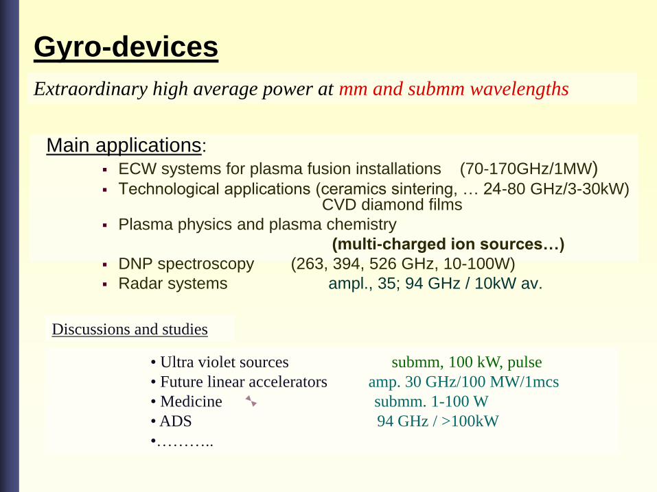
Gyro-devices
Main applications:
ECW systems for plasma fusion installations (70-170GHz/1MW) Technological applications (ceramics sintering, … 24-80 GHz/3-30kW)
CVD diamond films
Plasma physics and plasma chemistry
(multi-charged ion sources…)
DNP spectroscopy (263, 394, 526 GHz, 10-100W)
Radar systems ampl., 35; 94 GHz / 10kW av.
Extraordinary high average power at mm and submm wavelengths
• Ultra violet sources submm, 100 kW, pulse
• Future linear accelerators amp. 30 GHz/100 MW/1mcs
• Medicine submm. 1-100 W
• ADS 94 GHz / >100kW
•………..
Discussions and studies
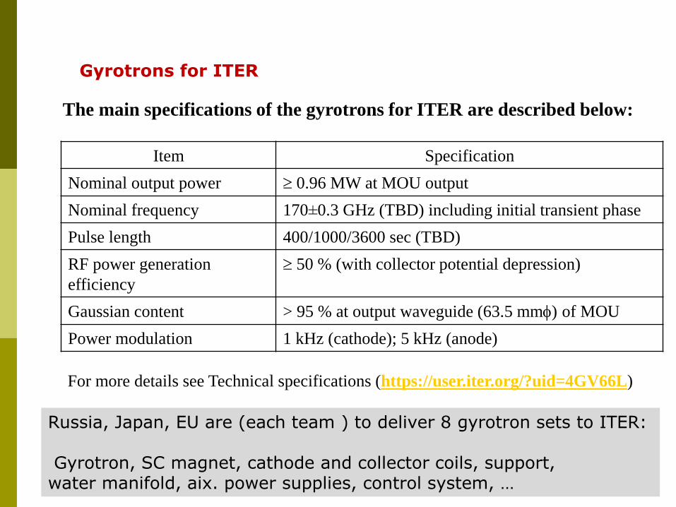
The main specifications of the gyrotrons for ITER are described below:
Item Specification
Nominal output power 0.96 MW at MOU output
Nominal frequency 170±0.3 GHz (TBD) including initial transient phase
Pulse length 400/1000/3600 sec (TBD)
RF power generation
efficiency
50 % (with collector potential depression)
Gaussian content > 95 % at output waveguide (63.5 mm) of MOU
Power modulation 1 kHz (cathode); 5 kHz (anode)
For more details see Technical specifications (https://user.iter.org/?uid=4GV66L)
Gyrotrons for ITER
Russia, Japan, EU are (each team ) to deliver 8 gyrotron sets to ITER: Gyrotron, SC magnet, cathode and collector coils, support, water manifold, aix. power supplies, control system, …
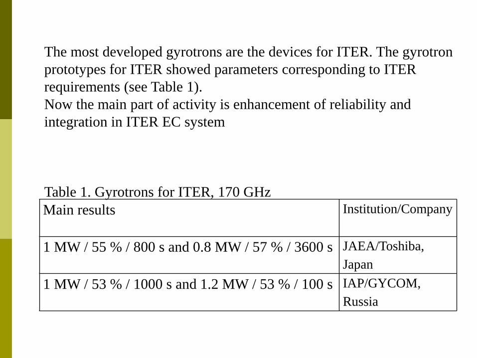
Main results Institution/Company
1 MW / 55 % / 800 s and 0.8 MW / 57 % / 3600 s JAEA/Toshiba,
Japan
1 MW / 53 % / 1000 s and 1.2 MW / 53 % / 100 s IAP/GYCOM,
Russia
The most developed gyrotrons are the devices for ITER. The gyrotron
prototypes for ITER showed parameters corresponding to ITER
requirements (see Table 1).
Now the main part of activity is enhancement of reliability and
integration in ITER EC system
Table 1. Gyrotrons for ITER, 170 GHz
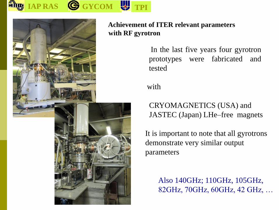
Achievement of ITER relevant parameters
with RF gyrotron
with
CRYOMAGNETICS (USA) and
JASTEC (Japan) LHe–free magnets
It is important to note that all gyrotrons
demonstrate very similar output
parameters
In the last five years four gyrotron
prototypes were fabricated and
tested
IAP RAS GYCOM TPI
Also 140GHz; 110GHz, 105GHz,
82GHz, 70GHz, 60GHz, 42 GHz, …

Institute of Applied Physics RAS
High Voltage
Power SupplyGyrotron
Transmission
LineApplicator
Solenoid
Power SupplyPower Meter
Process
Parameters
PC - based Control
SystemThe systems are made up as standard
computer-controlled setups with the
feedback loop for power control.
At present more than 40 systems produced jointly by the IAP and Gycom Ltd. are
operating throughout the world. Output power ranges are usually from 3 to 15 kW at
frequencies 24 – 30GHz.
GYCOM
Second Harmonic Gyrotrons for Technological Applications

Main features of low frequency CW gyrotrons
Output mode waveguide operating mode
Number of harmonic 2
Type of the magnet electromagnet with water or oil cooling,
permanent magnet
Operating frequency 24 – 30 GHz
Output power <25 kW
Accelerating voltage <25 kV
Anode voltage <10 kV
Beam current <2.5 A
700 - 1000 mm
Ø <60 mm
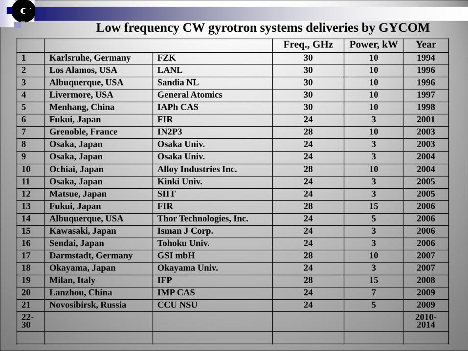
Low frequency CW gyrotron systems deliveries by GYCOM
Freq., GHz Power, kW Year
1 Karlsruhe, Germany FZK 30 10 1994
2 Los Alamos, USA LANL 30 10 1996
3 Albuquerque, USA Sandia NL 30 10 1996
4 Livermore, USA General Atomics 30 10 1997
5 Menhang, China IAPh CAS 30 10 1998
6 Fukui, Japan FIR 24 3 2001
7 Grenoble, France IN2P3 28 10 2003
8 Osaka, Japan Osaka Univ. 24 3 2003
9 Osaka, Japan Osaka Univ. 24 3 2004
10 Ochiai, Japan Alloy Industries Inc. 28 10 2004
11 Osaka, Japan Kinki Univ. 24 3 2005
12 Matsue, Japan SIIT 24 3 2005
13 Fukui, Japan FIR 28 15 2006
14 Albuquerque, USA Thor Technologies, Inc. 24 5 2006
15 Kawasaki, Japan Isman J Corp. 24 3 2006
16 Sendai, Japan Tohoku Univ. 24 3 2006
17 Darmstadt, Germany GSI mbH 28 10 2007
18 Okayama, Japan Okayama Univ. 24 3 2007
19 Milan, Italy IFP 28 15 2008
20 Lanzhou, China IMP CAS 24 7 2009
21 Novosibirsk, Russia CCU NSU 24 5 2009
22-30
2010-2014

Institute of Applied Physics RAS
5 kW 24 GHz Gyrotron-based system for materials processing
Dir.coupler
Polarizer
Mode converter
applicator
magnet
gyrotron
HV and magnet power supply
GYCOM

Institute of Applied Physics RAS
5 kW 24 GHz system with a permanent magnet
f 40 GHz - “warm” (water or oil cooled) solenoid or permanent magnet
( magnetic field for second harmonic operation ~ 0.5 T)
f 40 GHz - superconducting solenoid (LHe or LHe- free, last one consumes 5-10 kW)
GYCOM
Institute of Applied Physics RAS
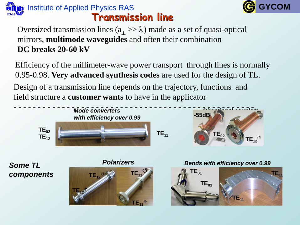
Transmission line Oversized transmission lines (a
┴ >> ) made as a set of quasi-optical
mirrors, multimode waveguides and often their combination
DC breaks 20-60 kV
Efficiency of the millimeter-wave power transport through lines is normally
0.95-0.98. Very advanced synthesis codes are used for the design of TL.
Design of a transmission line depends on the trajectory, functions and
field structure a customer wants to have in the applicator
- - - - - - - - - - - - - - - - - - - - - - - - - - - - - - - - - - - - - - - - - - - - - - - - - - Directional couplers Mode converters
with efficiency over 0.99
TE02
TE12 TE11
TE01
TE01
TE11
TE02
Bends with efficiency over 0.99
-55dB
TE11
TE12
Polarizers
TE12
TE12
TE11
TE11
Some TL
components
GYCOM
Institute of Applied Physics RAS
Example (2009)
The major output characteristics of the electron cyclotron resonance ion sources
(ECRIS), such as the total ion current and the mean ion charge, could be improved
with an increase in frequency of the applied microwave power. Recently experimental
verification of the frequency scale up has been extended to frequencies of 28 GHz.
Microwave power of the order of several or tens of kilowatts in CW regime, required
for feeding of ECRIS aimed to practical use, can be provided at frequencies of about
tens GHz with gyrotrons only.
Gyrotron-based system with output power of 7 kW at frequency of 24 GHz has been
developed by the Institute of Applied Physics jointly with GYCOM Ltd for powering the
SECRAL Superconducting ECR Ion Source of the Institute of Modern Physics, China
Academy of Sciences, Lanzhou.
GYCOM

Institute of Applied Physics RAS
MAJOR TECHNICAL CHARACTERISTICS
Operating frequency 24 GHz 50 MHz
Operation regime either CW or pulse mode
Output microwave power 0.1 kW – 7 kW, smoothly controlled
Output mode/Mode entering ion source TE12 / TE01
DC break in transmission line 40kV
Mode purity (whole system) 98% minimum TE01, 2% other modes
Power adjustability 100 W … 7 kW with an increment 25 W
RMS ripple ≤ 1%
Power stability vs time* better than 0.25 dB/24 h
Power stability vs temperature* better than 0.05 dB/C in the range 20 C – 30 C
Power stability vs mains voltage* less than 1% for a mains variation of 20 V
Pulse mode operation
Fall time RF / Rise time < 30 μs / < 500 μs
Pulse duration RF 5 – 100 ms or CW
Repetition rate 1 – 10 s-1
GYCOM
Institute of Applied Physics RAS
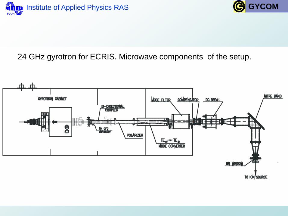
24 GHz gyrotron for ECRIS. Microwave components of the setup.
GYCOM
Institute of Applied Physics RAS
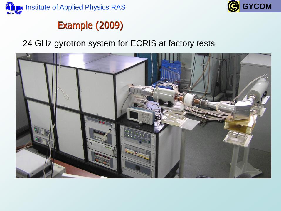
Example (2009)
24 GHz gyrotron system for ECRIS at factory tests
GYCOM

Frequency and power rise of CW gyrotrons by
operation at first harmonic in cryomagnets
Main features of CW gyrotrons at cryomagnets
- triode-type electron gun
- gyrotron is installed in cryomagnet warm bore
from cathode side
- lateral direction of output Gaussian wave beam by
quasi-optical build-in converter
- setting diameters in cryomagnet bore 110 – 140 mm
- efficiency of gyrotron 50-60 %

Typical scheme of gyrotron system
Filament
Cathode
Cryo-
MOU Calorimetric load
Waveguide line
Test benchwith equipment
Calorimetric
MOU
Cryomagnet
Anode
Gyrotron
magnet
load
Gyrotron
Test benchwith equipment
System output
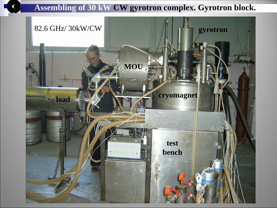
Assembling of 30 kW CW gyrotron complex. Gyrotron block.
load
MOU
gyrotron
cryomagnet
test
bench
82.6 GHz/ 30kW/CW

Helical-waveguide gyro-TWTs
principles
recent activity at IAP/GYCOM
Gyro-amplifiers
More difficult than oscillators


Summary
Gyrotrons by IAP/GYCOM :
Fusion 170 GHz, 1 MW/1000sec + other frequencies
Technology (examples) 24 GHz ; 28 GHz/10kW/ CW
82.6 GHz / 25 kW/ CW
60 GHz double regime: 300kW /0.1-10 ms and 20 kW/CW
300 GHz/ 3 kW/ CW
Ka band / 2GHz/ 7kW /CW amplifier
Gyro-oscillators: any frequency (20-200 GHz); any power (1kW-1MW)
Gyro-amplifiers : 20-40 GHz/ ~10 kW/ δf~ 2 GHz
Gyrotron developers are waiting for ECRIS requests