mine impact burial prediction from one to three dimensions
TRANSCRIPT

1
pmbtfalpp
oagbewmwm
dttmtmt
U
A
Downlo
Peter C. Chu1
Naval Ocean Analysis and Prediction Laboratory,Naval Postgraduate School,
Monterey, CA 93943e-mail: [email protected]
Mine Impact Burial PredictionFrom One to Three DimensionsThe Navy’s mine impact burial prediction model creates a time history of a cylindrical ora noncylindrical mine as it falls through air, water, and sediment. The output of the modelis the predicted mine trajectory in air and water columns, burial depth/orientation insediment, as well as height, area, and volume protruding. Model inputs consist of param-eters of environment, mine characteristics, and initial release. This paper reviews nearthree decades’ effort on model development from one to three dimensions: (1) one-dimensional models predict the vertical position of the mine’s center of mass (COM) withthe assumption of constant falling angle, (2) two-dimensional models predict the COMposition in the �x ,z� plane and the rotation around the y-axis, and (3) three-dimensionalmodels predict the COM position in the �x , y , z� space and the rotation around the x-, y-,and z-axes. These models are verified using the data collected from mine impact burialexperiments. The one-dimensional model only solves one momentum equation (in thez-direction). It cannot predict the mine trajectory and burial depth well. The two-dimensional model restricts the mine motion in the �x ,z� plane (which requires motion-less for the environmental fluids) and uses incorrect drag coefficients and inaccuratesediment dynamics. The prediction errors are large in the mine trajectory and burialdepth prediction (six to ten times larger than the observed depth in sand bottom of theMonterey Bay). The three-dimensional model predicts the trajectory and burial depthrelatively well for cylindrical, near-cylindrical mines, and operational mines such asManta and Rockan mines. �DOI: 10.1115/1.3013823�
Keywords: mine impact burial prediction, Kirchhoff–Kelvin equation, IBPM,IMPACT25/28, IMPACT35, drag and lift forces and torques, translation velocity,orientation, burial depth, sediment dynamics, triple coordinate system, mine shape effect,cylindrical mine, Manta mine, Rockan mine
IntroductionIn mine hunting, success often hinges on knowing as much as
ossible about the mines that have been placed and the environ-ent that has affected the placement. Since bottom mines cannot
e searched visually, and are often difficult to locate with conven-ional sonar, an estimate of area and height of the mine protrudingrom the sediment, or the burial depth, is crucial for the planningnd execution of mine clearance operations. Determining theikely mine burial depth requires numerical models of the burialrocess and knowledge of the environment, including sedimentroperties, waves, tides, and water depth.
Sea deployed mines currently used by the United States andther nations fall into three general categories: bottom, moored,nd drifting mines. Bottom mines rest on the ocean floor and areenerally deployed in littoral regions. Common placements forottom mines include shipping channels, harbors, anchorages, riv-rs, and estuaries. Bottom mines are deployed in one of the threeays: aircraft, surface ship, and submarine. Mine impact burialodels have been developed to predict mine’s motion in air andater and to determine the burial depth in sediment when theine comes to rest in the sediment.One-dimensional impact burial prediction model �IBPM� was
eveloped by Arnone and Bowen �1� to predict the vertical posi-ion of the cylindrical mine’s center of mass �COM� as it fallshrough air, water, and sediment. The burial depth of the mine in
arine sediment is then calculated from the mine’s velocity andhe sediment characteristics. IBPM only solves the vertical mo-
entum equation with the assumption of an unchanged orienta-ion in the fluid.
1Corresponding author.Published online December 16, 2008. Transmitted by Assoc. Editor Firdaus E.
dwadia.
pplied Mechanics Reviews Copyright © 20
aded 18 Dec 2009 to 137.229.21.11. Redistribution subject to ASME
Satkowiak �2,3� advanced Arnone and Bowen’s �1� pioneeringwork through correcting reference flow for drag and added-masscalculations; reworking equations for sediment-cavity regime,drag due to the cylindrical and rounded noses, and resistant forcesin semisolid sediment; and including water temperature effect onthe water viscosity. The major weakness of the one-dimensionalmodel is the mine’s orientation �or the falling angle� assumedconstant as it falls through the fluid.
Two-dimensional models were developed first by Hurst to over-come the major weakness of IBPM �constant falling angles� �4�.The models, written in BASIC �IMPACT25� and in MATLAB �IM-PACT28�, contain two momentum equations �in the x- andz-directions� and one moment-of-momentum equation �in they-direction�, include Mulhearn’s �5� formulation for sedimentbearing strength, and use multilayered sediments. They predictmine COM position in the �x ,z� plane and the rotation �i.e., mineorientation� around the y-axis.
Although the two-dimensional models advance our knowledgeon the mine movement by including its rotation around the y-axis,it is very difficult to include the motion of the fluid. This is be-cause it is hard to assume the fluid �air, water, and sediment�movement strictly in the �x ,z� plane. Any fluid motion in they-direction induces drag force and in turn causes the mine move-ment �in the y-direction�, which breaks the two-dimensional sce-nario �6,7�. In fact, it is impossible to lay a mine in the samevertical plane of the fluid velocity. Sensitivity studies onIMPACT25/28 burial depth show the insensitivity of the minereleasing height and the water temperature �8�. A mine drop ex-periment at Monterey Bay �9–11� shows that IMPACT25/28 over-predicts the burial depth.
Three-dimensional model �IMPACT35� has been developedwith the support from the Office of Naval Research through MineBurial Prediction Program �12–15�. The model contains three mo-
mentum equations and three moment-of-momentum equations. ItJANUARY 2009, Vol. 62 / 010802-109 by ASME
license or copyright; see http://www.asme.org/terms/Terms_Use.cfm

prmSCeg
temam
2
c�cpifixtc
F„
Cr
0
Downlo
redicts the mine’s COM position in the �x ,y ,z� space and theotation �i.e., mine’s orientation� around the three axes. Severaline drop experiments conducted at the Naval Postgraduatechool �NPS�, Naval Undersea Warfare Center �NUWC�-arderock, and Baltic Sea �by the German Navy� were used tovaluate the two- and three-dimensional models. The results showreat improvement of the three-dimensional modeling.
The one-, two-, and three-dimensional models are reviewed inhis paper. Basic physics, formulation, strength, and weakness ofach model are presented. The purpose is to provide a overview ofore than two decades’ effort on predicting the mine �cylindrical
nd operational mine shape� movement in the air, water, and sedi-ent column.
Mine Location and OrientationConsider an axially symmetric cylinder with the COM X �or
alled gravity center �GC� in literatures� and the center of volumeCOV� B on the main axis �Fig. 1�. Let �L ,R ,�� represent theylinder length, the radius, and the distance between the twooints �X ,B�. The positive �-values refer to the nose-down case,.e., point X is lower than point B. Let FE�O , i , j ,k� be the earth-xed coordinate �E-coordinate� with the origin O, and three axes:-, y-axes �horizontal� with the unit vectors �i , j� and z-axis �ver-ical� with the unit vector k �upward positive�. The position of theylinder is represented by the position of the COM,
ig. 1 M-coordinate with the COM as the origin of X andim , jm… as the two axes. Here, � is the distance between theOV „B… and Com „X…, and „L ,R… are the cylinder’s length and
adius „after Chu et al. †13‡….
Fig. 2 Mine’s COM position „x ,z… and
10802-2 / Vol. 62, JANUARY 2009
aded 18 Dec 2009 to 137.229.21.11. Redistribution subject to ASME
X = xi + yj + zk �1�
which is a translation of the cylinder. The translation velocity isgiven by
dX
dt= V, V = �u,v,w� �2�
The orientation of the cylinder’s main axis �pointing down-ward� is given by iM. The angle between iM and k is denoted by�2+� /2 �Fig. 2�. The angle �2 is the mine falling angle. In theone- and two-dimensional modelings, only the E-coordinate sys-tem is used. In three-dimensional modeling, two extra-coordinatesystems �main-axis following and force following coordinates� arealso used.
3 Triple Coordinate SystemsThree coordinate systems are used in mine impact burial pre-
diction modeling: earth-fixed coordinate �E-coordinate�, main-axis following coordinate �M-coordinate�, and force following co-ordinate �F-coordinate� systems. All the three coordinate systemsare three dimensional, orthogonal, and right handed �16�. Projec-tion of the mine’s main-axis vector iM onto the �x ,y� plane createsangle ��3� between the projection and the x-axis �Fig. 2�. TheM-coordinate is represented by FM�X , iM , jM ,kM� with the originX �i.e., the COM location�, unit vectors �iM , jM ,kM�, and coordi-nates �xM ,yM ,zM�. The unit vectors of the M-coordinate systemare given by
jM = k � iM, kM = iM � jM �3�
The M-coordinate system is solely determined by orientation ofthe cylinder’s main axis iM.
The F-coordinate is represented by FF�X , iF , jF ,kF� with theorigin X, unit vectors �iF , jF ,kF�, and coordinates �xF ,yF ,zF�. LetVw be the fluid velocity. The water-to-mine velocity is representedby
Vr = Vw − V �4�
which can be decomposed into two parts
Vr = V1 + V2, V1 = �Vr · iF�iF, V2 = Vr − �Vr · iF�iF �5�
where V1 is the component paralleling to the cylinder’s main axis�i.e., along iM�, and V2 is the component perpendicular to the
orientation �2 „after Chu et al. †16‡…
Transactions of the ASME
license or copyright; see http://www.asme.org/terms/Terms_Use.cfm

cF
TR
4
inoTKf
cms�tfdrbtttplpap�c
dtneovbtliwica
wsdft
w�tttfpt
A
Downlo
ylinder’s main-axial direction. The unit vectors for the-coordinate are defined by �column vectors�
iF = iM, jF = V2/�V2�, kF = iF � jF �6�
ransforms among the three coordinate systems can be found inef. �16�.
One-Dimensional ModelingOne-dimensional models assume that the cylinder is not rotat-
ng �i.e., constant orientation� about any axis, nor a net fluid dy-amic lift. Consequently, it can only be applied to stable motionf the body along one of its major axes �horizontal or vertical�.he models predict the COM location �i.e., z� using theirchhoff–Kelvin theory. Only the E-coordinate system is used
or the one-dimensional modeling.
4.1 Kirchhoff–Kelvin Theory. In the later half of the 19thentury, Kirchhoff and Kelvin showed that the motion of a solidoving through an ideal fluid could be represented by a compact
ystem of equations describing the coupled fluid-body dynamics17,18�. Publications about the implications and extensions of thisheory �cited as the Kirchhoff–Kelvin equations hereafter� wererequent from the 1870s until the 1900s, when experimental aero-ynamics showed the limitations of the idealized models in rep-esenting the coupled dynamics of bodies and complex turbulentoundary layer regimes. Interest in the subject also waned due tohe daunting nonlinearity of the governing equations. Recentlyhere has been a resurgence of interest in the Kirchhoff–Kelvinheory, since the widespread availability of highly capable com-uters has allowed numerical analysis of problems involving non-inear dynamics �19–21�. Even when analytical closure is notractical, the general results of the Kirchhoff–Kelvin equationsid heuristic explanations of the observed dynamics of more com-lex shapes, such as coins �very short cylinders� sinking in water22� and tumbling cards �23�. In Ref. �24�, excellent introductoryan be found to the Kirchhoff–Kelvin equations and implications.
In general, the Kirchhoff–Kelvin equations predict the coupledynamic response of arbitrary solid bodies to various forces andorques within inviscid incompressible flow. For high Reynoldsumber regimes �Re=UD /��104, where U is the velocity, D isither the length or diameter of the cylinder depending on releaserientation, and � is the kinematic viscosity�, the direct effect ofiscosity is small such that coherent structures of the turbulentoundary layer diminish. The typical value of Re for mine fallinghrough the water column is around 105 �15�. This condition al-ows the generalized dynamics of falling bodies to be character-zed in terms of a simplified form of the Kirchhoff–Kelvin theoryhere buoyancy force and turbulent drag are balanced by the
nertia of the cylinder and displaced water. For a freely sinkingylinder of diameter d and length l, the combined effect of buoy-ncy and gravity per unit volume is
B = − �� − �w�g �7�
here g is the gravitational acceleration, and ��−�w� is the den-ity difference of the cylinder and water. The flow over the cylin-er surface yields pressure distributions that result in a net dragorce �Fd� on the body, empirically represented as proportional tohe square of the body’s speed through water,
Fd � 12�wCdU2� �8�
here Cd is the drag coefficient, U is the mine’s falling speed, andis an effective cross-sectional area normal to the flow. Under
he assumption that the torques exerted by wake pressure fluctua-ions are insignificant, the phenomenological representation of theotal drag force on the cylinder can be used in an approximationor the falling motion where the rate of change in kinetic energy isarametrized by the rate of change of the cylinder momentum and
he acceleration of the “virtual mass” of the displaced waterpplied Mechanics Reviews
aded 18 Dec 2009 to 137.229.21.11. Redistribution subject to ASME
�which depends upon the geometric characteristics of the body�.Thus, the force balance on the cylinder is given by
d2z
dt2 =�wCd�
2��1 + f��dz
dt�2
−�� − �w�
�g +
F
��9�
where is the volume of the mine, f is the effective added-massfactor or the virtual mass coefficient of the system due to theacceleration of water around the moving body, and F is the addi-tional sediment force, which is zero in air and water. The left-handside of Eq. �9� shows the vertical acceleration of the mine per unitmass. The right-hand side of Eq. �9� shows the external forces perunit mass exerted on the mine, with the first term from the dragforce �Fd�, the second term from the buoyancy force �B�, and thethird term from the sediment resistance.
Full implementation of the theory is not the focus of this work;however, stability analysis of particular variants of the Kirchhoff–Kelvin equation provides useful insights. We can characterize thegeneralized dynamics governing the motions of mines fallingthrough water under the following hypothetical situations: verticaldescent with the axis of the cylinder aligned parallel to the flow orvertical descent with the axis of the cylinder aligned perpendicularto the flow. For the simplest case where the axis of the cylinder isaligned with the fall direction, body motions will be stable unlessthey are significantly disturbed in a direction normal to the mo-tion. This means that a vertically oriented cylinder dropped freelywill maintain this orientation until external forces, such as vari-able turbulent drag, cause the motion to become unstable resultingin changes in orientation. With the axis of the cylinder orientedhorizontally, or normal to the trajectory, the motion is also stable.An alternative scenario where the axis of the cylinder is not ini-tially aligned either parallel or perpendicular to the flow makes theapplication of the above equations difficult but has been addressedin Ref. �25�, who established that with time, the falling body willassume a horizontal orientation where the torque exerted on thebody by the water turns the main axis of the cylinder, so that it isnormal to the relative flow �“broadside”�. This configuration isstable when the exposed area is normal to the flow and is signifi-cantly greater than the cross-sectional area of the “nose-on” atti-tude. Slight variations of this stable mode also exist includingregular oscillations, glide tumble motions, and helical motions.
4.2 IBPM. The one-dimensional model is the first generationof the Navy’s mine impact burial model �1–3�, called the IBPM.This model is used to predict the vertical location and orientationof a cylindrical mine falling through air, water, and sedimentthrough solving the Kirchhoff–Kelvin equation �9�. The modelconsists of four major components: �a� steady falling attitude ��2�,�b� drag computation, �c� cavity regimes, and �d� sediment forces.
4.2.1 Steady Falling Angle in Single Media. IBPM does notuse the moment-of-momentum equation for predicting mine ori-entation. Instead, the tangent of the falling angle �or called atti-tude� ��2� is assumed as the ratio of moments due to the axial �Fa�and cross �Fc� forces �1�:
tan �2 =moment�Fa�moment�Fc�
�10a�
where the axial and cross forces are calculated by
Fa = g�� − f1�w sin2 �2�, Fc = g�� − f2�w cos2 �2� �10b�
Here, �f1 , f2� are the effective added-mass factors in the axial andcross mine directions,
f1 =0
2 − 0, f2 =
�0
2 − �0�11�
The two parameters �0 ,�0� depend only on the aspect ratio ���,
4� 4
− 1� −1
ln�2 + �� −�
,
0 � �2 2 2 − � 2�JANUARY 2009, Vol. 62 / 010802-3
license or copyright; see http://www.asme.org/terms/Terms_Use.cfm
T
F�ti�dTa
wFodadS
il
ico
Tm
ditficcv=
tdtA
0
Downlo
�0 4
�2 −1
�� 4
�2 − 1�ln�2 + �
2 − ��, �
2R
L�12�
he effective added-mass factor is computed by
f = f2 sin �2 + f1 cos �2 �13�
or an attitude �2 of 0 deg �vertical�, f equals f1. For an attitude2 of 90 deg �horizontal�, f equals f2. In IBPM, the mine’s atti-
ude ��2� is obtained by solving Eqs. �10a� and �10b� using theteration method. Since the expression �10b� uses the fluid density�w�, the mine’s attitude ��2� does not change in a single fluid butoes change when it passes through the interface of two fluids.he effective cross-sectional area �or sometimes called projectedrea� � depends on the attitude �2,
� = 2LR sin �2 + �R2 cos �2 �14�
hich is used for the drag calculation �see the next subsection�.or an attitude of 0 deg �vertical�, � equals �R2. For an attitudef 90 deg �horizontal�, � is the product of the length �L� andiameter �2R�. It is noted that the physical base for “constant �2 insingle fluid” is weak. This is because the mine’s attitude ��2� is
etermined by solving the moment-of-momentum equation �see
ecs. 5.1 and 6.1� rather than solving Eqs. �10a� and �10b�.lthough it is difficult to actually determine these volumes, the
10802-4 / Vol. 62, JANUARY 2009
aded 18 Dec 2009 to 137.229.21.11. Redistribution subject to ASME
4.2.2 Drag Coefficient. Drag is caused by hydrodynamicforces acting on the falling cylinder in the axial and cross direc-tions, and therefore it depends on the attitude ��2� of the cylinder.The drag becomes somewhat more complicated because the fea-ture of the flow across the cylinder changes based on the magni-tude of the Reynolds number,
Re =2UR
��15�
where � is the kinematic viscosity of the fluid. When the Reynoldsnumber is small � 1�, skin friction dominates but as the Reynoldsnumber increases, a more laminar flow occurs and the pressuredrag dominates. At a certain and critical Reynolds number �104�,flow becomes turbulent and drag abruptly decreases. Reynoldsnumber is thus dependent on velocity of the cylinder and must beconstantly recalculated as the cylinder falls through each medium.
Dependence of drag on �Re, �2� is shown in the axial and crossdrag coefficients �Cda ,Cdc� �1�
Cdc = 1.1�Cd� sin2 �2, Cda = 1.1Cd*
�
2RL�16�
where
Cd� =�0.84864 + 5.81939/Re if Re � 4 � 103
�0.5833 � 10−4�Re + 0.61677 if 4 � 103 Re � 104
1.2 if 104 Re � 8 � 104
1.19381 + �0.65828 � 10−6�Re − 10−11 Re2 if 8 � 104 Re � 5 � 105
8 � 10−7 Re − 0.15 if Re � 5 � 105 �17�
s the cross flow drag coefficient for the cylinder with infiniteength �Cd��, and
Cd*= 0.33� +
3.984�Re
1
�+ �1/2� �18�
s the axial drag coefficient with no surface imperfections. Theoefficient of 1.1 in Eq. �16� is used to account for imperfectionsf the cylinder with the correction factor � given by
� = 0.52238 + 0.021191
�− 0.00048�1
��2
�19�
he total drag coefficient �Cd� for computing the drag force on aine moving through the fluid is calculated by
Cd = Cda + Cdc sin2 �2 �20�
4.2.3 Air-Water Cavity. Upon impacting the water, the cylin-rical mine enters the air-water cavity. The properties of the fluidn the water cavity are combination of air and water fluid proper-ies and are continuously changing with time. It is extremely dif-cult to accurately predict the forces acting on a body in a fluid ofhanging properties �1,26�. The changing properties around theylinder through the cavity are the fluid density and kinematiciscosity. For example, the fluid density changes from air ��a
1.29 kg m−3� to sea water ��w=1025 kg m−3�.Within the air-water cavity regime, a percentage of each of
hese densities is used in determination of the resulting averageensity. This is represented by the ratio �called the void ratio� ofhe volume of water in the cavity to the total cavity volume.
trend of this ratio is known. For example, the void ratio equals “0”for the cylinder in the air and equals “1” for the cylinder totallywetted in the water.
When the pressure generated by the dynamic loading of thecylinder impacting on the water is balanced by the hydrostaticpressure of the water. The air-water cavity is assumed to collapseand the cylinder is fully wetted. The dynamic pressure generatedby the cylinder �pD� is the sum of the atmospheric pressure pa
�=100 kPa� at the water surface and dynamic pressure due to thecylinder’s falling velocity U,
pD�t� = pa + 12�w�U�t��2 �21a�
The hydrostatic pressure �pS� of water is the sum of the atmo-spheric pressure �pa� and weight of the water column,
pS�t� = pa − �wgz�t� �21b�
In the IBPM, the square root of the ratio between pD and pS isdefined as the void ratio n0
n0�t� =�pD�t�pS�t�
�22�
which is taken as a weight of water in the air-water cavity. Thecavity density ��w
cav� and viscosity ��wcav� are calculated by
�wcav = �a�1 − n0� + �wn0,
1
�cav�cav =�1 − n0�
�a�a+
n0
�w�w�23�
w w
Transactions of the ASME
license or copyright; see http://www.asme.org/terms/Terms_Use.cfm

ccc
Sc
toccotm
iH
awc
T
wiEc
areca
wpt
Tt
wsbci
pt
A
Downlo
The dynamic effect of cavitation on the body is through thehange of the Reynolds number �in turn the change of the dragoefficient�. The Reynolds number for the air-water cavity is cal-ulated by
Rewcav =
2UR
�wcav
ubstitution of Rewcav into Eqs. �16�–�20� leads to the drag coeffi-
ient for the air-water cavity.
4.2.4 Water-Sediment Cavity. Upon impacting the sediment,he cylindrical mine creates a cavity in which the fluid propertiesf water and sediment are interacting. Similar to the air-wateravity regime, the properties of the water-sediment cavity areombination of water and sediment properties and are continu-usly changing with time. In the water-sediment cavity regime,he fluid density changes from water ��w=1025 kg m−3� to sedi-ent �s. Within the water-sediment cavity, the void ratio n1
n1�t� =�pD�t�pS�t�
�24�
s taken as the weight of the sediment in water-sediment cavity.ere,
pD�t� = pa + �wgh + 12�s�U�t��2, pS�t� = pa + �wgh − �sg�z�t� + h�
�25�
re the dynamic and static pressures, and h is the water depth. Theater-sediment cavity density ��s
cav� and viscosity ��scav� are cal-
ulated by
�scav = �w�1 − n1� + �sn1,
1
�scav�s
cav =�1 − n1�
�w�w+
n1
�s�s�26�
he kinematic viscosity of the sediment is determined by
�s = �w +S
�sdU/dz�27�
here S is the shear strength of the sediment. Substitution of �snto Eq. �15� leads to a new Reynolds number; and then use ofqs. �16�–�20� leads to the drag coefficient for the water-sedimentavity.
4.2.5 Sediment Forces. Forces exerting on mine in sedimentre different from that in air and water, especially the sedimentesistant force �F�, which is calculated in IBPM using two differ-nt methods. The first method �1� is velocity independent. It de-omposes the sediment resistant force into compressive force �FC�nd shearing force �FS�,
F = FC + FS �28a�
here �FC ,FS� are proportional to the shear strength �S� with theroportionalities of the cylindrical reference flow areas �� f ,�s� inhe front �twice� and in the side �once�,
FC = 2S� f, FS = S�s �28b�
he second method is velocity dependent �3�. The sediment resis-ant force is calculated by
F = EsS�Nb� f + Saf�s/St� �29�
here Es is the sediment strain rate �i.e., ratio of the sedimenttrength for a given velocity of the cylinder�, Nb �=10� is theearing capacity factor, Saf is the side adhesive factor �0.3 for theavity and 1.0 for sediment�, and St �=3� is the sediment sensitiv-ty coefficient.
Thus, the sediment shear strength and density data are the in-uts to the Kirchhoff–Kelvin equation �9� for mine movement in
he sediment since they are needed for determination of the sedi-pplied Mechanics Reviews
aded 18 Dec 2009 to 137.229.21.11. Redistribution subject to ASME
ment’s compressive and shearing forces, buoyancy force, addedmass, drag force, and kinematic viscosity. Since the properties ofsediment change with depth, the sediment density and shearstrength profiles with 5 cm vertical resolution are used in theIBPM.
4.3 Sensitivity Studies. For a single medium, after the atti-tude ��2� is determined from Eq. �10a� and �10b�, the effectivecross-sectional area � and the effective added-mass factor f canbe calculated using Eqs. �11� and �12�, and then the total dragcoefficient Cd can be computed using Eq. �20�. For sediment, thecompressive and shear stress forces �FC ,FS� are computed fromthe density and shear strength. With the known parameters ��, f ,Cd, FC, and FS�, the Kirchhoff–Kelvin equation �9� can be solvedfor mine movement. For mine penetration into the air-water andwater-sediment interfaces, the total drag coefficient Cd
cav is calcu-lated from the cavity density ��w
cav or �scav� and viscosity ��w
cav or�s
cav�.Arnone and Bowen �1� conducted a model sensitivity study on
the mine air weight �or wet weight�, length, and radius. The model�9� was integrated with various combinations of these parametersand three different attitudes: �2=0 deg, �horizontal�, 45 deg, and90 deg �vertical�. The water impact velocity has the followingfeatures. �a� For mine movement in the air, as one would expect,the more streamlined the falling attitude �i.e., �2=90 deg verti-cal�, the higher velocity the cylindrical mine falls. �b� The waterimpact velocity varies drastically with the attitude for light mines.Such an effect reduces as the mass increases. �c� The water impactvelocity is not sensitive to mine length �L� and radius �R�.
The mine falling velocity in the water has the following char-acteristics. �a� It varies drastically with attitude and wet weight.For the same wet weight, the mine falls faster for �2=90 deg�vertical� than for �2=0 deg �horizontal�. For the same �2, themine falls faster for heavier wet weight. �b� It is not sensitive toattitude for short mines and is very sensitive to attitude for longmines. �c� It is not sensitive to mine length for horizontal release��2=0 deg� and is very sensitive to mine length for vertical re-lease ��2=90 deg�. �d� It is not sensitive to attitude for small Rand is very sensitive to attitude for large R. �e� It is not sensitiveto attitude for small R and is very sensitive to attitude for large R.
4.4 Strength and Weakness. IBPM has capability to simulatemine falling velocity in the air and water columns. As mentionedin the previous subsection, the model provides the following use-ful results: �a� The mine has higher falling velocity for verticalrelease ��2=90 deg� than for the horizontal release ��2=0 deg�,�b� the water impact velocity varies drastically with the attitudefor light mines but does not for heavy mines, and �c� the minefalling velocity in water column is sensitive to attitude, wetweight, mine length, and mine radius. For the same mine, thefalling velocity in water is minimum for horizontal orientation andmaximum for vertical orientation.
Weakness of the IBPM is to assume the constant attitude ��2�during the mine falling through a single medium �air, water, orsediment� �Fig. 3�, which is physically unrealistic �12�. In fact, theorientation changes for any solid object falling through fluid �airand water�. When COV is not colocated with COM, the buoyancyforce �B� has a moment of momentum exerted on mine �Fig. 4��27�. If the mine slants toward left �right�, the moment of momen-tum due to the buoyancy force will rotate the mine clockwise�anticlockwise�. This causes the spiral motion for mine fallingthrough fluid.
5 Two-Dimensional ModelingTo overcome the major weakness of the one-dimensional model
�i.e., constant attitude �2�, Hurst �4� modified the IBPM modelthrough allowing the cylinder to move both vertically and hori-
zontally �in the �x ,z� plane� as well as rotation about the y-axis.JANUARY 2009, Vol. 62 / 010802-5
license or copyright; see http://www.asme.org/terms/Terms_Use.cfm

TsM
�g
wt�it
FdC
Ft
0
Downlo
hese changes mandated the use of more complicated dynamicalystem than the IBPM. Two coordinate systems �E- and
-coordinates� are used in the two-dimensional models.
5.1 Dynamical System. Let the cylinder be moving in thex ,z� plane. The momentum equations in the �x ,z� directions areiven by
d2x
dt2 du
dt=
Fhx
��30�
d2z
dt2 dw
dt= − g +
B + Fhz
��31�
here B is the buoyancy force, and �Fhx ,Fh
z� are the components ofhe hydrodynamic force Fh. Since the cylinder is restricted in thex ,z� plane, the only possible rotation is around the y-axis, whichs described by the attitude �2. The moment-of-momentum equa-ion is written in the M-coordinate system,
ig. 3 Mine’s orientation is assumed constant by the one-imensional model when it falls through a single fluid „afterhu †12‡…
ig. 4 Change of mine orientation caused by momentum due
o the buoyancy force „after Chu †27‡…10802-6 / Vol. 62, JANUARY 2009
aded 18 Dec 2009 to 137.229.21.11. Redistribution subject to ASME
J2d2�2
dt2 = B� cos �2 + Mhy �32�
where J2 is the moment of inertia in the y-axis, and Mhy is called
the braking torque in Ref. �4�.
5.2 IMPACT25/28. The two-dimensional models, usuallycalled IMPACT25 �written in BASIC� and IMPACT28 �written inMATLAB�, are the second generation of the Navy’s mine impactburial prediction models for cylindrical mines and were based onEqs. �30�–�32� for obtaining �x ,z ,�2�. The external forcing forIMPACT25/28 consists of drag force �Fh
x ,Fhz� and braking torque
�Mhy�. Since the mine movement is restricted in the �x ,z� plane, it
is very hard to include the motion of the fluids �air or water�. Ifthe fluid has velocity in the y-direction, the mine’s motion cannotbe two dimensional. Thus, in IMPACT25 and IMPACT28, thefluid �air or water� is assumed motionless.
5.2.1 Drag Force. The drag force for the whole cylinder iscalculated in two directions: along the cylinder’s main axis �iM�and across the cylinder �kM�,
Fd = − Fd�iM sin �2 − kM cos �2� �33�
where Fd is computed using the drag law
Fd = 12�wCd�u2 + w2�� �34�
The drag coefficient Cd is computed by
Cd = Cd + Cdn �35�
where Cd is computed in the same way as in the one-dimensionalmodel �i.e., Eq. �20��, and Cdn is the drag coefficient for the nose.
5.2.2 Braking Torque. The braking torque Mhy in Eq. �32� is
calculated by
Mhy = − 1
6CdcR�w�2L3Vc �36�
where
Vc = u cos �2 + w sin �2 �37�
is the cross-cylinder velocity. Equation �36� is only used when themine is fully immersed in a single fluid. During the cavity re-gimes, a different calculation is applied. Furthermore, the torqueis in opposite sign to rotation and thus acts as the brake to therotation of mine. For a single fluid, the basic equations �30�–�32�are integrated in association with Eqs. �33� and �36�.
5.2.3 Sediment. The one-dimensional models �IPBM and itsmodifications� treat sediment as fluid with two characterized pa-rameters: sediment density and shear strength. Different from theone-dimensional models, the two-dimensional models treat thesediment as solid that undergoes plastic deformation �4�. The per-tinent parameters are sediment density and bearing strength. Thebearing strength is the load bearing capacity of the sediment anddefined as the pressure in front of the object penetrating the sedi-ment. It is related to the shear strength, typically larger by a factorof about 10. Three elements contributing to the sediment resis-tance on the penetration of a falling mine are included inIMPACT25/28: bearing strength of the sediment �70%�, hydrody-namic drag �25%�, and buoyancy �5%� �4�.
As the mine penetrates the sediment, the hydrodynamic dragthat retards the penetration is calculated by
Fd =�s��u2 + w2�
2�C1
h
L+ C2� �38�
where C1 and C2 are the drag coefficients for low Reynolds num-ber and h is the depth in sediment. The buoyancy force comes into
play when the mine impacts the sediment. A crater is formed andTransactions of the ASME
license or copyright; see http://www.asme.org/terms/Terms_Use.cfm

tb
aweTclaac
pmnafodd
wtatcc
Wdp
dtcavpa
srwdldiAta
tbdfdhia
A
Downlo
he force that is required to create and enlarge the crater is giveny Eq. �4�
B = �gh��w − ��� �39�
Two assumptions are made regarding the mine. First, the buoy-ncy force acts uniformly on the portion of the mine in contactith the sediment. Second, a cavity is formed, remains at the aft
nd of the mine, and leads the mine surface to the buoyancy force.he second assumption is not always true. For some cases, theavity collapses under the weight of the sediment. The collapseimit is defined and approximated as the depth where the buoy-ncy force is 20% of the bearing force. Besides, the drag, buoy-ncy, and bearing strength of sediment all depend on the mineontact area �.
5.2.4 Air-Water Cavity. As mentioned before, when the mineenetrates the air-water interface, it forms a cavity behind theine that changes the drag forces. Throughout the cavity regimes,
onsymmetric forces are acting on the mine that generate torquend affect the rate of rotation. The cavity parametrization is dif-erent between the two-dimensional models �IMPACT25/28� andne-dimensional model �IPBM�. The cavity formation in the two-imensional models is controlled by the cavitation number �Ncav�efined by
Ncav =2�pout − pin��w�u2 + w2�
�40�
here �pout , pin� are the hydrodynamic pressure outside �i.e., wa-er� and inside the cavity. Pressure difference between the outsidend inside of the cavity increases or the mine’s velocity decreases;he cavitation number increases until the eventual collapse of theavity. The drag coefficient of the cavity is the function of theavitation number,
Cd�Ncav� = Cd�1 + bNcav� �41�
hen the air-water cavity collapses, Ncav=0, Cd�0� is the waterrag coefficient. The torque in the air-water cavity can be com-uted after the drag coefficient is determined.
5.3 Sensitivity Study. Sensitivity studies �8,28� were con-ucted on the two-dimensional model �IMPACT25/28� to ascer-ain which parameters the model is most sensitive to and whichan be eliminated in order to simplify its use. The model wasltered to allow most parameters to be set and a loop run for oneariable at a time. All model runs were made with preset minerofile, which has a dry weight of 538 kg, a wet weight of 251 kg,nd a uniform diameter of 0.475 m.
5.3.1 Sensitivity to Release Parameters. Figure 5 demon-trates the sensitivity of the release altitude and other model pa-ameters such as water depth and water temperature. Altitude,hen varied from 0 m to 1000 m, has a small effect on burialepth �relative difference of 18%�. When a more realistic upperimit of 300 m for a mine laying aircraft is applied, the relativeifference drops to 9%. Water depth affects the burial depth onlyf a mine reaches the terminal velocity �in this case about 20 m�.lthough temperature varies the water density up to 3% and in
urn changes the viscosity �29�, it does not affect the burial depthnd orientation.
For vertical initial falling angle �Fig. 6� with zero rotation rate,he mine is heading directly downward, resulting in the maximumurial depth. When the release height is 150 m, the mine burialepth is 2.405 m for the vertical initial falling angle and 0.359 mor the horizontal initial falling angle. Such a difference in burialepth decreases as the release height decreases. When the releaseeight is 1.5 m, the mine burial depth is 0.977 m for the verticalnitial falling angle and 0.342 m for the horizontal initial falling
ngle.pplied Mechanics Reviews
aded 18 Dec 2009 to 137.229.21.11. Redistribution subject to ASME
5.3.2 Sensitivity to Sediment Characteristics. Figure 7 showsthe sensitivity of sediment density and shear strength on burialdepth. For the shear strength of 1 kPa �extremely soft sediment�,the burial depth decreases 37% for sediment density varying from1000 kg /m3 to 2000 kg /m3. For more commonly used values ofshear strength �5–15 kPa�, the sediment density has very littleeffect, just 3.7% �Fig. 7�a��. As shear strength increases, the in-fluence of sediment density reduces. For constant sediment den-sity �1.5 kg m−3�, the impact burial depth drastically reduces from0.55 m for the shear strength of 1 kPa to 0.1 m for the shearstrength of 10 kPa �Fig. 7�b��.
A power law is used
S = �s� �42�
to represent the relationship between sediment density ��s� andshear strength �S� �30�. Here the two coefficients and � aredetermined experimentally. Considering a homogeneous sedimentlayer ��s=const�, the shear strength is a function of � ,��. For agiven �s, increasing or � enhances the shear strength �S� and inturn decreases the burial depth. These features are well simulatedby the model �Fig. 8�.
5.4 Strength and Weakness. The improvement of the two-dimensional model versus the one-dimensional model is its capa-bility to predict the mine rotation in the �x ,z� plane, i.e., �2. In thetwo-dimensional model, the momentum equation for the �x ,z� di-rections and the moment-of-momentum equation for the
Fig. 5 Effect of „a… release attitude, „b… water depth, and „c…water temperature on burial depth. Values are primarily chosento represent all conditions under which IMPACT25 and IM-PACT28 may be used „after Chu et al. †28‡….
y-direction are used to predict the position and orientation around
JANUARY 2009, Vol. 62 / 010802-7
license or copyright; see http://www.asme.org/terms/Terms_Use.cfm

tmm
hbfl
0
Downlo
he y-axis �i.e., in the �x ,z� plane�. The basic physics for the spiralotion described in Fig. 4 is included in the two-dimensionalodel but strictly in the �x ,z� plane �31,32�.Since the mine movement is strictly in the �x ,z� plane, it is very
ard to include the motion of fluid in the two-dimensional modelecause it is impossible to lay a mine in the same direction of theuid velocity. In the littoral zone, the water velocity is not negli-
Fig. 6 Dependence of „a… burial depth „m… and „b… height proprotruded is illustrated here to clarify the levels at which themodels „after Chu et al. †28‡….
Fig. 7 Effect of sediment „a… density and „b… shimpacts the predicted burial depth in very soft sed
impact on predicted burial depth „after Chu et al. †310802-8 / Vol. 62, JANUARY 2009
aded 18 Dec 2009 to 137.229.21.11. Redistribution subject to ASME
gible. The application of the two-dimensional model for the op-erational use is limited. Besides, the drag coefficients for the axialand cross directions have similar dependence on the Reynoldsnumber Re and the aspect ratio ��� �see Eqs. �17� and �18��. How-ever, the drag coefficients in the axial and cross directions areindependent �33�. Besides, a mine drop experiment shows thatIMPACT25/28 overpredicts �five to ten times larger� the mine
ding „m… on release altitude „m… and water depth „m…. Heightparameters become less influential in the two-dimensional
r strength on burial depth. Density change onlyents. As expected, shear strength has a dramatic
truse
eaim
1‡…
Transactions of the ASME
license or copyright; see http://www.asme.org/terms/Terms_Use.cfm

bm
6
mlrIdpnd
t
aM
Ff
A
Downlo
urial in the sandy bottom �9,31,32�. This indicates that the sedi-ent dynamics is too simple in the two-dimensional model.
Three-Dimensional Modeling for Cylindrical MinesTo overcome the major weaknesses of the two-dimensionalodel, i.e., �a� environmental fluid assumed motionless, �b� simi-
ar drag coefficients in the axial and cross directions, and �c� non-ealistic sediment dynamics, Chu et al. �10–16,34–38� modifiedMPACT25/28 allowing the cylinder to move in three-imensional space. These changes mandated the use of more com-licated dynamical system than IMPACT25/28. The three coordi-ate systems �E-, F-, and M-coordinates� are used in the three-imensional modeling.
6.1 Dynamical System. The three momentum equations �inhe E-coordinate system� are given by
d
dt�u
v
w� = − �0
0
g� +
Fb + Fh
��43�
nd the three moment-of-momentum equations �in the-coordinate system� are written in vector form
J ·d�
= − 2J · �� � �� + Mb + Mh �44�
ig. 8 Effect of � and � on predicted burial depth „m… for dif-erent values of sedimentary density „after Chu et al. †31‡…
dt
pplied Mechanics Reviews
aded 18 Dec 2009 to 137.229.21.11. Redistribution subject to ASME
Here, �Fb ,Mb� are the buoyancy force and torque, and �Fh ,Mh�are the hydrodynamic force and torque including the drag, lift, andimpact �Fd ,Fl ,Fi ;Md ,Ml ,Mi�. The vectors �� ,�� are the angu-lar velocity of mine and M-coordinate system,
� = �2jM + �3kM �45�
The first term in the right-hand side of Eq. �44� is an apparenttorque �similar to the Coriolis term in earth science� due to the useof the rotating coordinate system �i.e., the M-coordinate�. If �1=0, then �=�. The apparent torque is given by
− 2J · �� � ��
= �0 if �1 = 0 �i.e.,� = ��− 2J2�1�3jM + 2J3�1�2kM if �1 � 0
��46�
The gravitational force, passing the COM, does not induce themoment. In the M-coordinate system, the moment of gyrationtensor for the axially symmetric cylinder is a diagonal matrix
J = �J1 0 0
0 J2 0
0 0 J3� �47�
where J1, J2, and J3 are the moments of inertia. The buoyancyforce induces the moment in the jM direction if the COM does notcoincide with the COV �i.e., ��0�,
Mb = �Fb�� cos �2jM �48�
6.2 IMPACT35-Cylindrical. The three-dimensional model,usually called IMPACT35 �written in MATLAB�, is the third gen-eration of the Navy’s mine impact burial prediction model. Forcylindrical mines, it is called IMPACT35-Cylindrical orIMPACT35C. It was developed to solve the six scalar equations�43� and �44� to obtain �x ,y ,z ,�1 ,�2 ,�3�. From the angular ve-locity ��1 ,�2 ,�3�, the three angles determining the mine orienta-tion ��1 ,�2 ,�3� can be obtained,
d�1
dt= �1,
d�2
dt= �2,
d�3
dt= �3
The external forcing for IMPACT35 consists of drag force Fd andtorque Md, as well as lift force Fl and torque Ml. All these exter-nal forces and torques are calculated in the F-coordinate system.The model includes cylindrical and noncylindrical mines. In thissubsection, the cylindrical mine is taken as an example for illus-tration.
6.2.1 Drag and Lift Forces. Two features of the drag and liftcoefficients �Reynolds number dependent and asymmetry inalong- and across-mine main axis� distinguish IMPACT35 fromIMPACT25/28. The drag and lift forces are calculated using theF-coordinate system. Let �Cd1 ,Cd2� be the drag coefficientsalong- and across-mine main axis and �f1 , f2 , f3� be the added-mass corrections �f1 , f2 , f3� in the three directions of theF-coordinate system.
The total drag force along iF �i.e., relative flow along the cyl-inder’s main axis� is calculated by
Fd1 = Ctd1�t�V1, Ctd1�t� Cd1�R2
2
�w
�1 + f1��V1�t�� �49�
Cd1 is almost independent of the axial Reynolds number �Re�4
when Re�10 but dependent on the cylinder’s aspect ratio �33�,JANUARY 2009, Vol. 62 / 010802-9
license or copyright; see http://www.asme.org/terms/Terms_Use.cfm

i
T
wc
dcmc
wtmcm
kat
0
Downlo
Cd1 = �1.0 if � � 8
0.75 + �/32.1934 + 0.09612/�2 if 8 � � � 0.5
1.15 if � � 0.5
The total drag force along jF �i.e., relative flow across the cyl-nder� is calculated by
orque on the cylinder in the jF direction,
10802-10 / Vol. 62, JANUARY 2009
aded 18 Dec 2009 to 137.229.21.11. Redistribution subject to ASME
Fd2 = R�−L/2−�
L/2−�
Cd2�V2��2 �w
�1 + f2�dx, V2��x� = V2 − �3
Fx �50�
where V2� is the water-to-cylinder velocity at the surface in the jFdirection and an empirical formula is used for calculating Cd2�39�,
Cd2 =�1.9276 + 8/Re if Re � 12
1.261 + 16/Re if 12 Re � 180
0.855 + 89/Re if 180 Re � 2000
0.84 + 0.00003 Re if 2000 Re � 12,000
1.2 − 4/� if 12,000 Re � 150,000, � � 10
0.835 − 0.35/� if 12,000 Re � 150,000, 2 � � 10
0.7 − 0.08/� if 12,000 Re � 150,000, � 2
1.875 − 0.0000045 Re if 150,000 Re � 350,000
1/�641550/Re + 1.5� if Re � 350,000
�51�
The drag force along kF is calculated by
Fd3 = Cd2R�w
�1 + f2��2
F��2F���
0
L/2−�
x2dx −�−L/2−�
0
x2dx��kF
�52�
he water-to-cylinder velocity determines the lift force �40�,
Fl = Ctl�t�L �
−L/2−�
L/2−�
V2��x�dx�kF, Ctl�t� ClLR�w
�1 + f2��V2�
�53�
here Cl is the lift coefficient. An empirical formula is used foralculating Cl �41�,
Cl = �2�1R/V2 if �1R/V2 � 4
8 + 0.24��1R/V2 − 4� if �1R/V2 � 4� �54�
6.2.2 Drag and Lift Torques. For an axially symmetric cylin-er, the moment of the hydrodynamic force in iF direction is notaused by the drag and lift forces, but by the viscous fluid. Theoment of the viscous force of steady flow between two rotating
ylinders with the common axis is calculated by �42�
M = 4��r1
2 · r02
r12 − r0
2 ��1 − �0�
here �r1 ,r0� and ��1 ,�0� are the radii and the angle velocities ofhe inner and outer cylinders; � is the dynamic viscosity. The
oment of the viscous force on one rotating cylinder is the limitase of the two rotating cylinders as r0→� and �0=0. The mo-ent of the viscous force around iF is calculated by
Mv1 = − Cm1�1iF, Cm1 ��Ld2 �55�
Same as the hydrodynamic forces, the torques along the jF andF axes, �Md1 ,Md2 ,Ml�, are calculated. When the cylinder rotatesround jF with the angular velocity �2
F, the drag force causes a
Md2 = − �2F��2
F��−L/2−�
L/2−�
Cd2R�w
�1 + fr�x2�x�dx�jF �56a�
where fr is the added-mass factor for the moment of drag and liftforces. If the water-to-cylinder velocity or the cylinder mass dis-tribution is nonuniform ���0�, the drag force causes a torque onthe cylinder in the kF direction,
Md3 = �−L/2−�
L/2−�
Cd2R�w
�1 + fr��V2 − �3
Fx�2xdx�kF �56b�
The lift force exerts a torque on the cylinder in the jF direction,
Ml2 = −�−L/2−�
L/2−�
ClR�w
fkr�V2 − �3
Fx�xdx�jF �57�
6.2.3 Interfacial Treatment. Computation of buoyancy and hy-drodynamic forces �Fb ,Fh� and torques �Mb ,Mh� is more compli-cated for a cylinder penetrating through air-water and water-sediment interfaces than falling through a single medium such aswater. At the instance when the cylinder penetrates into an inter-face, three situations may exist: the cross section is a completeellipse �Fig. 9�a��, a cutoff ellipse with one side straight line �Fig.9�b��, or a cutoff ellipse with two straight lines �Fig. 9�c��. Theinterface separates the cylinder to two parts. Each part contains anoncylinder D and a subcylinder C �Fig. 10�. Let �Lc ,Ld�,��c ,�d�, and �c ,d� be the lengths, surfaces, and volumes of�C ,D�, and �h1 ,h2� be the depths of the two sides of D �Fig. 11�.The characteristics of the geometric parameters �Lc ,h1 ,h2� arelisted in Table 1. The COV for the portion �C ,D� is called thepartial COV �PCOV�. With this treatment, the drag and lift forcesand torques at the two parts C and D can be computed separately�36�.
6.2.4 Sediment Resistance. In the two-dimensional models,IMPACT25/28, the pertinent parameters are sediment density andbearing strength. The bearing strength is calculated simply by tentimes the shear strength, which is not very realistic. In fact, whenthe mine impacts and penetrates into the sediment, it will create alarge transient pore pressure in the sediment that causes ruptures
in the sediment and influences the resistance force on the mineTransactions of the ASME
license or copyright; see http://www.asme.org/terms/Terms_Use.cfm

sIor
sts
F†
T†
UoULUo
A
Downlo
urface �11,36�, which is not simply ten times the shear strength.n the three-dimensional model �IMPACT35�, two distinct meth-ds �delta and bearing factor� are used to compute total sedimentesistance force and torque.
(a) Delta method. The delta method is developed on the as-umption that the mine pushes the sediment and leaves space inhe wake as it impacts and penetrates into the sediment. Thispace is refilled by water and the water cavity is produced �Fig.
Fig. 9 Three patterns of cylinder penetraplete ellipse „b… cutoff ellipse with one sideside straight lines „after Chu and Fan †36‡…
ig. 10 Illustration of PCOV „B−…, x1, and �− for the tail part
C„1… ,D„1…‡ for the case in Fig. 9„a… „after Chu and Fan †36‡…
Fig. 11 Geometry of part D„1…„after Chu and Fan †36‡…
able 1 Geometric parameters during the cylinder penetration36‡
Lc h1 h2
pper and lower partsf Fig. 9�a�
�0 2R 0
pper part of Fig. 9�b� �0 2R 0–2Rower part of Fig. 9�b� 0 0–2R 0pper and lower partsf Fig. 9�c�
0 0–2R 0–2R
pplied Mechanics Reviews
aded 18 Dec 2009 to 137.229.21.11. Redistribution subject to ASME
12�. At the instance of the penetration, the total sediment shearresistant force on the mine surface is calculated by �36�
Fs =��sed
����G�V�S�z��d� −��sed
n���z
zws
�s�z��gdz��+ �wg�zws − z��d� + k
�
8�s�z��gw
kp+
1 + ev
ev
dw
dt�B3 �58�
where in the right-hand side the first term is the shear resistanceforce, the second term is the buoyancy force, and the third term isthe pore water pressure. S�z� is the sediment shear strength, G�V�is the impact function, V is the mine translation speed, �s�z� is thesediment wet density �usually obtained from the sediment data�,�n ,�� are unit vectors normal �outward positive� and tangential tothe mine surface, zws represents the vertical coordinate of thewater-sediment interface kp is the permeability coefficient�10−4 m s−1, �43��, ev ��0.50� is the void ratio, and B is the lengthof the rupture line. The step function � is defined by
� = �1, v · n � 0
0, v · n � 0� �59�
which shows that the sediment buoyancy and shear resistanceforces act when the cylinder moves toward it. Let vn be the nor-mal velocity. The tangential velocity is represented by
v� = v − vn �60�
The tangential unit vector ��� is defined by
� = −v�
�v���61�
which is opposite to v� �Fig. 13�.The sediment resistance torque �Ms� is calculated by
with the cross section being „a… a com-aight line, and „c… a cutoff ellipse with two
Fig. 12 The impact „resistant… force exerted on the part of themine surface moving toward the sediment „after Chu and Fan
tionstr
†36‡…
JANUARY 2009, Vol. 62 / 010802-11
license or copyright; see http://www.asme.org/terms/Terms_Use.cfm
wt
odtat
Ts
Hd�a
we
mmPmta
Fp
0
Downlo
Ms =��sed
�r � �����G�V�S�z��d�
+��sed
�r � n����z
zws
�s�z��gdz�� + �wg�zws − z��d�
+ �rpw � k��
8�s�z��gw
k+
1 + ev
ev
dw
dt�B3 �62�
here rpw is the position vector �in the M-coordinate� indicatinghe location of the cylinder’s rupture line.
(b) Bearing factor method. The bearing factor method is basedn the fact that the shear resistance force �Fr
s� is in the oppositeirection of v and acts on the mine. Its magnitude is proportionalo the product of the sediment shear strength �S� and the rupturerea �A is projection of sediment-contacting area perpendicular tohe velocity V� with a non-negative bearing factor N �44�,
Frs = −�
�sed
�N�p,v�SAd�, N � 0 �63�
he sediment resistance torque includes the hydrodynamic andhearing resistance torques,
Ms =��sed
�r � fhs − �N�p,v�SA�r � ��d� �64�
ere, p is the non-dimensional penetration depth scaled by theiameter �2R�. The sediment density and shear strength S in Eqs.63� and �64� are measured. The bearing factor increases with pnd decreases with the decreasing speed,
N�p,v� = ��1p�2�1 + � log� vvcri
�� �65�
here � is the v-effect parameter, ��1 ,�2� are the p-effect param-ters �16�, and vcri is the critical speed.
6.2.5 Pseudocylinder parametrization. The Navy operationalines are usually not cylindrical. It is important to develop aodel with more general shapes such as with nose and tail.seudocylinder parametrization was proposed for noncylindricalines �35�. For a near-cylindrical mine with nose and tail falling
hrough a single medium or multiple media, the buoyancy force
ig. 13 Momentum and angular momentum balance for mineenetration through the water-sediment interface
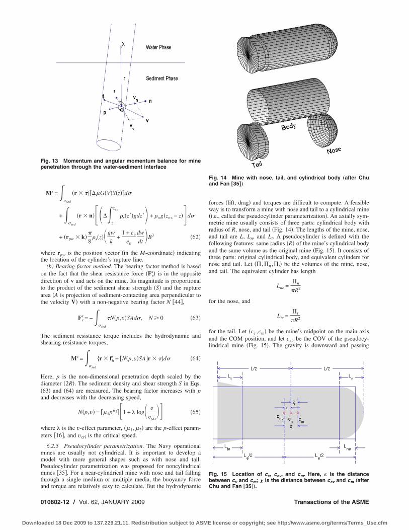
nd torque are relatively easy to calculate. But the hydrodynamic
10802-12 / Vol. 62, JANUARY 2009
aded 18 Dec 2009 to 137.229.21.11. Redistribution subject to ASME
forces �lift, drag� and torques are difficult to compute. A feasibleway is to transform a mine with nose and tail to a cylindrical mine�i.e., called the pseudocylinder parameterization�. An axially sym-metric mine usually consists of three parts: cylindrical body withradius of R, nose, and tail �Fig. 14�. The lengths of the mine, nose,and tail are L, Ln, and Lt. A pseudocylinder is defined with thefollowing features: same radius �R� of the mine’s cylindrical bodyand the same volume as the original mine �Fig. 15�. It consists ofthree parts: original cylindrical body, and equivalent cylinders fornose and tail. Let � ,n ,t� be the volumes of the mine, nose,and tail. The equivalent cylinder has length
Lne =n
�R2
for the nose, and
Lte =t
�R2
for the tail. Let �cc ,cm� be the mine’s midpoint on the main axisand the COM position, and let cev be the COV of the pseudocy-lindrical mine �Fig. 15�. The gravity is downward and passing
Fig. 14 Mine with nose, tail, and cylindrical body „after Chuand Fan †35‡…
Fig. 15 Location of cv, cev, and cm. Here, ε is the distancebetween cv and cm; � is the distance between cev and cm „after
Chu and Fan †35‡….Transactions of the ASME
license or copyright; see http://www.asme.org/terms/Terms_Use.cfm

tc
Lic
Brcp
VPfiMMsN2MbMotruwo
dmdtvtj
tIMza�4atc4Pj
A
Downlo
hrough cm. The buoyancy force is upward and passing throughev. Let �1 be the distances between cc and cm,
�1 =Ln − Lne
2−
Lt − Lte
2�66�
et �2 be the displacement from cc to cm that is easy to determinef COM is given. Let � be the displacement from cev to cm, that is,alculate
� = �1 + �2 �67�
oth � and �2 can be positive and negative. The positive valuesefer to nose-down case, i.e., the point cm is lower than the pointev for positive � and the point cc is lower than the point cev forositive �2.
6.3 Mine Impact Burial Experiment for Modelerification. The value added of three-dimensional model �IM-ACT35� versus two-dimensional model �IMPACT25/28� is veri-ed by several recent mine impact burial experiments �Table 2�:ine Impact Burial Experiment �MIBEX� at Monterey Bay onay 22, 2000 �9,31,32�, Mine Drop Experiment �MIDEX� at NPS
wimming pool in June 2001 �45,6,10,13,16,34�, MIDEX atSWC-Carderock Explosion Test Pond on September 10-14,001, and MIDEX at NSWC-Corpus Christi �46–48�. TheIDEX at the Baltic Sea experiment was conducted in June 2003
y the German Federal Armed Forces Underwater Acoustic andarine Geophysics Research Institute �49,50� with the full-size
ptical mine, which is allowed to free fall from the wench. Duringhese experiments, various model mines �most cylindrical� wereeleased into the water. The mine trajectories were recorded bynderwater high-speed video cameras. The mine burial depthsere also observed by the diver �in MIBEX-Monterey Bay� andptical instruments �in MIDEX-Baltic Sea�.
The two-dimensional model �IMPACT25/28� and three-imensional model �IMPACT35� are integrated using the sameine parameters �such as the density ratio, length, radius, and
istance between COV and COM� and mine drop initial condi-ions �speed and orientation� as in the mine drop experiments. Thealue added of IMPACT35 versus IMPACT25/28 is verifiedhrough comparison between the modeled and observed mine tra-ectories and burial depths.
6.4 Trajectory in Water Column. Detailed verification ofrajectory prediction in the water column by IMPACT35 andMPACT25/28 has been reported in Ref. �11� using data from
IDEX at NPS and MIDEX at NSWC-Caderock. For near hori-ontal release, the 3D model �IMPACT35� simulated trajectorygrees well with the observed trajectory with the same travel time1.91 s� of mine passing through the water column. For near5 deg release, the 3D model �IMPACT35� simulated trajectorynd travel time agree well with the observed trajectory. However,he 2D model �IMPACT28� has much less capability to predict theylinder trajectory in the water column with near horizontal and5 deg release. For near vertical release, the 3D model �IM-ACT35� simulated trajectory agrees well with the observed tra-
Table 2 Physical parameters of the model
Mine Mass �kg��
�103 kg m−3�L�
1 16.96 1.60 02 22.27 2.10 03 34.93 1.60 14 45.85 2.10 15 45.85 2.10 16 45.85 2.10 1
ectory with the same straight pattern and the same travel time
pplied Mechanics Reviews
aded 18 Dec 2009 to 137.229.21.11. Redistribution subject to ASME
�1.83 s� of mine passing through the water column. However, theexisting 2D model �IMPACT28� does not predict the travel timewell.
6.5 Burial Depth. MIBEX-Monterey Bay was conducted onthe R/V John Martin on May 23, 2000 �9,31�. The barrel with adensity ratio of 1.8 was treated as model mine and released hori-zontally while touching the surface. The initial conditions are
x�0� = y�0� = z�0� = 0, u�0� = v�0� = w�0� = 0
�2�0� = 90 deg, �1
�0� = �3�0� = 0, �1
�0� = �2�0� = �3
�0� = 0 �68�
This would be to eliminate any chance of inertial effects causedby uneven introduction into the air-sea interface. This also set theinitial velocity to zero. The barrel was released 17 times. Thediver would snap the quick-release shackle on the barrel and thendive down to conduct measurements. The average depth of thewater was 13 m. Since it was uncertain the path the barrel wouldfollow, both the releasing diver and a second safety diver wouldstay on the surface until after the barrel had dropped. Once reach-ing the bottom, one diver would take penetration measurementsusing a meter stick marked at millimeter increments while theother would take a gravity core. After 17 drops, the divers beganto run out of air and results were not varying greatly so the deci-sion was made to end the experiment. The gravity cores weretaken immediately to the USGS Laboratories in Menlo Park, CAto get the sediment density and shear strength profiles �Fig. 16�.
For sediment resistance force, the two-dimensional model�IMPACT25/28� uses ten times shear strength as the bearingstrength. The three-dimensional model �IMPACT35� uses thedelta or bearing factor method �see Sec. 6.2.4�. After running thetwo models �IMPACT35 and IMPACT25/28� for each gravitycore regime ��s�z� ,S�z�� from the initial conditions �69�, the burialdepths were compared with measured burial depth data �Fig. 17�.
es in the NSWC-Carderock experiment †47‡
J1�kg m2�
J2 �J3��kg m2�
��m�
0.0647 0.356 00.0806 0.477 00.1362 2.900 00.1696 3.820 00.1693 3.940 0.00450.1692 4.570 −0.077
Fig. 16 Mean sediment density s„z… and shear strength S„z…profiles in the Monterey Bay collected during the cylinder drop
min
m�
.505
.505
.010
.010
.010
.010
experiment on May 31, 2000
JANUARY 2009, Vol. 62 / 010802-13
license or copyright; see http://www.asme.org/terms/Terms_Use.cfm
A2a�eawlCipt
7
lsmlmtet
FacdfiwC
Ftbwc1awso
0
Downlo
s evident, IMPACT35 improves the prediction capability. TheD model �IMPACT25/28� overpredicts the actual burial depth byn order of magnitude on average. However, the 3D modelIMPACT35� predicts the burial depth reasonably well withoutvident overprediction. Since the gravity cores were taken forpproximately 2–3 m from the impact location, several coresere taken for each drop. This allowed an average to be calcu-
ated in order to yield more accurate data for each drop. Recently,hu and Fan �11� compared the delta and bearing factor methods
n IMPACT35C for sediment resistance using the Baltic Sea ex-eriment data and found that the bearing factor method is betterhan the delta method.
Modeling of Operational Mines
7.1 Shape Effect. Main limitation of IMPACT35C is its uti-ization for cylindrical and near-cylindrical mines only. Shape is aignificant issue if the model is used operationally because theost popular mines such as Rockan and Manta are far from cy-
indrical �Fig. 18�. To model the maneuvering of noncylindricalines in water column, the most important issue is to determine
he hydrodynamic �drag and lift� force and torque since there is noxisting formula for calculating the drag and lift forces andorques for noncylindrical objects. Shape effect is more tenuous
ig. 17 Observed „MIBEX-NPS… and predicted „IMPASCT25/28nd IMPASCT35 with Delta method… burial depths: „a… directomparison and „b… scatter diagram. Note that the two-imensional model „IMPACT25/28… predicts the burial depthve to ten times larger than the observed depth, and IMPACT35ith Delta method performs much better than IMPACT/28 „afterhu and Fan †36‡….
ig. 18 Operational mines: „a… Manta, and „b… Rockan. Here,he Manta is an anti-invasion bottom mine, produced primarilyy the Italian firm Whitehead Alenia. It is shaped as a frustumith a GRP casing, triggered either acoustically or magneti-ally. The Manta has a shelf life of 30 years and will operate for7 months after activation. The Rockan „made in Sweden… hasgliding shape, which allows mine laying over a wide areahile covering the minimal distance; its low-profile stealthhape makes it difficult to detect. Its casing is also constructed
f GRP.10802-14 / Vol. 62, JANUARY 2009
aded 18 Dec 2009 to 137.229.21.11. Redistribution subject to ASME
due to the lack of test data.MIDEX-II at NPS, conducted in September 2005, is a continu-
ation of mine drop experiments with operational mine shapes�51,52�. In that experiment, the overall shape of the mine wasnoncylindrical mines. In addition to a sphere and semihemispheri-cal Gumdrop shape, two shapes were specifically chosen to rep-resent real world bottom mines: the Manta and Rockan.
The Manta �Fig. 18�a�� is an anti-invasion bottom mine, pro-duced primarily by the Italian firm Whitehead Alenia. It is shapedas a combined frustum and flat cylinder with a glass reinforcedplastic �GRP� casing, triggered either acoustically or magnetically.The Manta has a shelf life of 30 years and will operate for17 months after activation.
The BGM-100 Rockan �Fig. 18�b�� is an acoustic and magneticmine, produced by Sweden. It has a gliding shape, which allowsmine laying over a wide area while covering the minimal distance.The low-profile stealth shape makes it difficult to detect. Its casingis also constructed of GRP. Both the Manta and Rockan are madeeven stealtheir by having anechoic coatings and being made of
Table 3 Physical parameters of Rockan mines
Diameter 0.980 mHeight 0.440 mWeight 220 kgCharge 130 kg �HBX-3�Operating depth 3–100 m
Table 4 Physical parameters of Manta mines
Length 1.015 mWidth 0.800 mHeight 0.385 mWeight 190 kgCharge 105 kg �Cemtex�Operating depth 105 kg
Table 5 Physical and geometrical features of model minesused in MIDEX-II
Model Mass Density Dimensions
Manta bottominfluence mineshape
1145.0 g 1.615 g /cm3 D �Bottom� 15.0 cmD �Top� 7.0 cmH 6.2 cmScale 1 /6Distance fromCOM to COV
+0.373 cmZ-axis
Rockan bottominfluence mineshape
813.0 g 1.388 g /cm3 L 16.0 cmW �Back� 7.8 cmW �Front� 13.3 cmH �Back� 6.3 cmH �Front� 3.8 cmScale 1 /6Distance fromCOM to COV
0 cm
Genericsphericalshape
1692.0 g 1.335 g /cm3 D 13.0 cmDistance fromCOM to COV
0 cm
Gumdrophemisphericalshape
2815.0 g 1.722 g /cm3 D 14.9 cmH 13.3 cmDistance fromCOM to COV
0 cm
Transactions of the ASME
license or copyright; see http://www.asme.org/terms/Terms_Use.cfm

nsa
tswtow
tscaiadTbTf
A
Downlo
onferrous materials to reduce the mines’ acoustic and magneticignatures. Tables 3 and 4 show the geometric and physical char-cteristics of Rockan and Manta mines.
7.2 MIDEX-II. The major objective of the MIDEX-II washe collection of trajectory data for operational mine shapes. Eachhape was dropped just above the surface of the water and filmedith a pair of high-speed cameras as the model mines fall through
he water column. Each trajectory was then converted to an arrayf Cartesian coordinates �E-coordinate� and analyzed with soft-are specifically designed to work with the high-speed cameras.Mine shapes are selected based upon current and future opera-
ional relevance. A collection of four minelike polyester resin testhapes were used. These shapes include sphere, semihemispheri-al “Gumdrop” shape, a scale model of the Manta bottom mine,nd a scale model of the Rockan bottom mine. The spherical mines selected to serve as a “calibration” shape because its symmetrynd equal weight distribution are about its three axes. The Gum-rop is similar in shape to but higher in density than the Sphere.he Gumdrop is selected to act as a kind of “traditional” shape ofottom sea mines, though no mine was specifically represented.able 5 shows the physical and geometrical characteristics of the
Fig. 19 Side and top views of the model minesManta and „b… Rockan. The construction of theprocess: prototype development, mold constructcess was necessary to facilitate more efficient exthe experimental test shapes.
our model mines. Figure 19 shows the geometric features, hori-
pplied Mechanics Reviews
aded 18 Dec 2009 to 137.229.21.11. Redistribution subject to ASME
zontal, and lateral views of Matha and Rockan model mines.MIDEX-II was conducted at the Monterey Bay Aquarium Re-
search Institute �MBARI� Unmanned Underwater Vehicle TestTank �Fig. 20�a��. Enclosed inside a large building, this 10�15�10 m3 tank is filled with “standard sea water.” This water ismaintained by an ozone filtration system, with no impurities thatsave the remnants of dye placed into the tank several weeks priorto the experiment. The faint coloration has no effect on the shapetrajectories, but it did add some difficulty illuminating the tank.Hence the video data quality is somewhat degraded. A slidingbridge, on which the slanted board is mounted, spanned the widthof the tank. Figure 20�b� describes the measurements of the tankand placement of the drop zone, cameras, and lighting.
The tank is used to simulate the littoral operating environmentwith the scaled depth ranging to 54.9 m �180 ft�; however, thenature of the viewing windows only allows data collection to ascaled depth of roughly 18.29 m �60 ft�. The tank has no currentand no wind blowing over its surface. To aid in shape recovery, a9�13 m2, 2 cm netting was mounted to a constructed 1.9 cmdiameter PVC piping horizontal grid and placed at the bottom ofthe tank out of camera view. At the end of a run, the net that
th different shapes for MIDEX-II experiment; „a…model mines consisted of a three-part product, and test shape casting, and finishing. This pro-imentation and to reduce the production cost of
wiseionper
contained the shapes was retrieved using a series of pulleys placed
JANUARY 2009, Vol. 62 / 010802-15
license or copyright; see http://www.asme.org/terms/Terms_Use.cfm

atvfdTs
statcntbwv
fFm
0
Downlo
t the four corners of the tank. Two large dark 4.57�5.18 m2
arpaulins were placed along the tank walls behind the cameraiews to assist the cameras and software with distinguishing thealling mine shapes from the tank background. Eight viewing win-ows �Fig. 20�c�� are 1.83 m �6 ft� below the surface of the water.he two viewing windows are selected because of the unob-tructed and near perpendicular view to the drop spot.
All the data were collected digitally using a network of high-peed and standard video equipment and computers. Data abovehe surface are collected using a pair of standard commerciallyvailable digital video camera, mounted on tripods, and located athe end of the pool directly in front of the testing zone. Both topameras operated at a 30 Hz frame rate. The data camera uses aarrow view lens zoomed to focus on the area directly betweenhe slanted board and the water surface, and is toggled on and offetween test runs. The second camera used a wide-angle lens andas employed to record a video log of the experiment. This de-ice ran continuously throughout the experiment.
Subsurface video data, used to determine the trajectory of thealling shapes, are collected using a pair of high-speed PhotronASTCAM PCI digital cameras �Fig. 20�d��. These cameras are
Fig. 20 MIDEX-II setup: „a… MBARI test tank facility „structvideo cameras, „c… view from underwater viewing window,Ã15Ã10 m3
… was filled with “standard sea water.” This wimpurities that save the remnants of dye placed into the tawhich the slanted board was mounted, spanned the width ofbelow the surface of the water. The two viewing windowsperpendicular view to the mine drop spot.
ounted on tripods in two separate windows, at an angle of
10802-16 / Vol. 62, JANUARY 2009
aded 18 Dec 2009 to 137.229.21.11. Redistribution subject to ASME
70 deg in relation to one another so as to provide two, near or-thogonal, views of the drop zone. After mounting and calibration,each camera station is covered with black plastic to block out anylight source beside that which comes from the field of view. Thecameras are synchronized, calibrated, and connected by a cen-trally located laptop computer via high-speed data cables. Duringtesting, the cameras are operated using the Photron FASTCAMViewer software at 512�480 pixel resolution at full frame andrecording rates of 125 Hz. To facilitate a wider field of view, bothcameras are fitted with wide-angle lens. All data are recordeddigitally on a standalone 200 Gbytes hard drive during the testphase. Additionally, to enhance the quality of the data during test-ing, the installed tank lighting system is turned to its maximumsetting and a pair of 1000 W high intensity photography lights aremounted and used above the surface.
The mine drop experiment consists of releasing each shape ver-tically from about 0.3 m �1 ft� above the surface of the water. Theentry of each shape into the water is recorded by the two above-surface video cameras. All subsurface data collection is facilitatedby the two FASTCAM PCI high-speed cameras. The subsurface
above water is a movable bridge…, „b… top view of the twod „d… calibration test cross. Here, the MBARI test tank „10r was maintained by an ozone filtration system, with no
several weeks prior to the experiment. A sliding bridge, ontank „see „a……. Eight viewing windows „c… were 1.83 m „6 ft…ed were selected because of the unobstructed and near
ureanate
nktheus
digital data are analyzed by 3D motion analysis software to deter-
Transactions of the ASME
license or copyright; see http://www.asme.org/terms/Terms_Use.cfm

FHMAXTRAQ, was the primary tool utilized to perform this function.
Applied Mechanics Reviews
Downloaded 18 Dec 2009 to 137.229.21.11. Redistribution subject to ASME
mine the trajectories of each shape. Overall, we have 15 drops ofthe Manta mine, 14 drops of the Rockan mine, 9 drops of theGumdrop, and 13 drops of the Sphere. Initial velocities of allshapes as they entered the water are calculated later using theMAXTRAQ motion analysis software.
7.3 Data Retrieval and Analysis. Data retrieval has been ac-complished following all the experimental test runs by convertingthe digital video imagery �Fig. 21� from each drop into an array of�x ,y ,z� coordinate data. Commercially available 3D motionanalysis software, MAXTRAQ, was the primary tool utilized to per-form this function. Initially, the software is calibrated into the 3Dcoordinate reference system utilizing the pairs of calibration im-ages obtained in the initial phase of the experiment. Following thecalibration, both camera views were time synced and analyzed todetermine the actual position of the shape in the �x ,y ,z� coordi-nate field. Frame by frame analysis was performed with the soft-ware for each view by manually identifying and inputting one ortwo marker points associated with the model mine’s position andorientation. For the Sphere and Gumdrop shapes, one markerpoint is used to identify the lowest position of the shape. For theManta mine, Point 1 �x1 ,y1 ,z1� and Point 2 �x2 ,y2 ,z2� are chosenas the centers of the bottom diameter and top diameter. Examplesof temporally varying data of �x1�t� ,y1�t� ,z1�t� ,x2�t� ,y2�t� ,z2�t��for the model Manta mine are listed in Table 6. From these data,the COM location �x ,y ,z� and the orientation ��2 ,�3� are calcu-lated �Table 7�.
For the Rockan mine, Point 1 �x1 ,y1 ,z1� is selected as the cen-ter of the narrow edge at the “electronics cylinder,” and Point 2�x2 ,y2 ,z2� is chosen as the center of the thicker edge of the shapeopposite to Point 1. In frames where a marker point was obscured,the position of the marker �Point 1 or Point 2� is estimated visu-ally based on the previous and next viewable frame. Following theanalysis of both views, the automated functions of the softwareare employed to compile the 2D images into a calibrated array of3D positional data. Examples of temporally varying data of�x1�t� ,y1�t� ,z1�t� ,x2�t� ,y2�t� ,z2�t�� for the model Rockan mine arelisted in Table 8. From these data, the COM location �x ,y ,z� andthe orientation ��2 ,�3� are calculated �Table 9�.
7.4 Trajectory Patterns. By analyzing the 2D and 3D plotsof each shape drop, the general trajectory patterns of the fourmines were obtained. The Sphere and Gumdrop mines are hydro-dynamically simple, resulting in the quickest drop times in theexperiment. The Gumdrop mine has the fastest mean travel timeto 2.5 m depth �1.462 s�. The Sphere favors a straight-arc trajec-tory �0.62 probability� over a curve-arc trajectory �0.38 probabil-ity�. The Gumdrop favors a curve arc �0.56 probability� over boththe straight arc �0.22 probability� and simple slant �0.22probability�.
The Manta and Rockan mines have more complicated shapes.Three trajectory patterns �flat spiral, side twist, and erratic� are
ines for a given initial velocity „3.116 m/s…
� x2 �m� y2 �m� z2 �m�
1 −0.2273 −0.6953 0.6371−1.1442 −0.2139 −3.5526
6 −0.7141 −0.9996 −9.47547 −1.141 −0.2135 −13.55766 −0.8558 −0.521 −18.86315 −0.9635 0.2915 −24.21113 −0.399 −0.5669 −28.81697 −0.8964 −1.0305 −33.98869 −1.0781 −1.6472 −38.51954 −0.236 −2.4716 −41.9996
¯ ¯ ¯
ig. 21 Examples of high-speed film frames for model mines.ere, the commercially available 3D motion analysis software,
Table 6 Examples of data for model Manta m
Time �s� x1 �m� y1 �m� z1 �m
0 0.2273 0.6953 −0.6370.016 −0.3519 2.4886 −2.8210.032 −0.3707 0.7862 −10.4690.048 −0.8714 0.531 −16.3910.064 −0.5257 0.1086 −21.6660.08 −0.2535 −0.3598 −26.5450.096 0.0811 −0.0842 −30.5540.112 0.0192 −0.8599 −35.7720.128 −0.3806 −2.0507 −39.9800.144 −0.111 −3.085 −43.488¯ ¯ ¯ ¯
JANUARY 2009, Vol. 62 / 010802-17
license or copyright; see http://www.asme.org/terms/Terms_Use.cfm

iattdot
0
Downlo
dentified for the Manta mine �Fig. 22�a��. Their characteristicsre listed in Table 10. For example, the flat spiral pattern showshe Manta mine falling with its bottom side basically parallel tohe X-Y plane and following a spiraling path. Table 11 shows theependence of trajectory pattern and travel time �to 2.5 m depth�n initial speed and orientation of the Manta mine. Three trajec-ory patterns �flip-dive-flat, flat-spin, and swoop-flat-spin� are
Table 7 Center of mass location „x ,y ,z… and ofrom the data shown in Table 6
Time �s� x �m� y �m�
0 0 00.016 −0.748 1.13730.032 −0.5424 −0.10670.048 −1.0062 0.15880.064 −0.6907 −0.20620.08 −0.6085 −0.03420.096 −0.1589 −0.32560.112 −0.4386 −0.94520.128 −0.7294 −1.8490.144 −0.1735 −2.7783¯ ¯ ¯
Table 8 Examples of data for Rockan m
Time �s� x1 �m� y1 �m� z1
0 −1.0736 0.5296 −50.016 −2.5339 −0.2221 −100.032 −4.0965 −0.3357 −120.048 −6.2738 −0.6902 −140.064 −7.6373 −0.3879 −130.08 −8.1222 −1.6365 −15
0.096 −7.7679 −1.6508 −150.112 −6.2722 −4.0571 −220.128 −4.3282 −5.2784 −240.144 −3.2107 −5.5892 −260.16 −1.1347 −5.8973 −28
0.176 −2.7208 −5.1987 −300.192 −2.4592 −5.3611 −320.208 −2.4199 −5.7808 −340.224 −1.7248 −6.6254 −360.24 −1.8801 −6.1255 −36¯ ¯ ¯
Table 9 Center of mass location „x ,y ,z… andrived from the data shown in Table 8
Time �s� x �m� y �m�
0 0 00.016 2.1797 −0.07150.032 1.1232 −0.40320.048 0.0413 −0.92280.064 −0.6934 −0.74050.08 −2.6173 −1.2710.096 −2.7506 −1.12650.112 −3.0753 −0.48090.128 −2.8128 −1.23470.144 −2.7269 −1.03140.16 −2.0879 −1.3665
0.176 −3.0125 −0.86990.192 −2.8262 −0.9960.208 −2.8488 −1.23120.224 −2.3318 −1.76860.24 −2.5402 −1.6581¯ ¯ ¯
10802-18 / Vol. 62, JANUARY 2009
aded 18 Dec 2009 to 137.229.21.11. Redistribution subject to ASME
identified for the Rockan mine �Fig. 22�b��. Their characteristicsare listed in Table 12. For example, the flip-dive-flat pattern showsthe Rockan mine flipping once, going into a vertical dive, andsettling into a slowly spinning horizontal orientation for the re-mainder of the drop. Table 13 shows the dependence of trajectorypattern and travel time �to 2.5 m depth� on initial speed and ori-entation of the Rockan mine.
ntation „�2 ,�3… for model Manta mine derived
z �m� � /2−�2 �3
0 −0.7165 −1.8868−3.1868 0.2542 −1.856−9.9725 −0.5003 −1.7608
−14.9747 −1.2983 −1.9182−20.2648 −1.3224 −2.0538−25.3783 −1.1793 2.3993−29.6856 −1.1973 −2.3535−34.8807 −1.0897 −2.9573−39.2502 −1.0669 2.6172−42.744 −1.1728 1.7718
¯ ¯ ¯
s for a given initial velocity „2.805 m/s…
� x2 �m� y2 �m� z2 �m�
1.0736 −0.5296 5.1666 6.8934 0.0791 −0.59338 6.3428 −0.4706 −5.23151 6.3564 −1.1554 −10.92242 6.2505 −1.0931 −15.92476 2.8875 −0.9055 −19.51885 2.2667 −0.6023 −21.30699 0.1216 3.0952 −13.97614 −1.2973 2.809 −17.4539 −2.2431 3.5264 −18.2012
2 −3.0412 3.1642 −19.85246 −3.3042 3.4589 −23.16969 −3.1931 3.3691 −24.81098 −3.2777 3.3184 −26.34427 −2.9388 3.0883 −27.49648 −3.2004 2.8093 −30.25
¯ ¯ ¯
ientation „�2 ,�3… for model Rockan mine de-
z �m� � /2−�2 �3
0 −1.3431 −0.4583−5.5765 −0.8129 0.0319−8.9761 −0.6223 −0.0129
−12.4968 −0.2442 −0.0368−14.747 0.1678 −0.0507
−17.3072 0.3813 0.0663−18.2462 0.5453 0.1041−18.1435 −0.7153 0.8413−21.1172 −0.7036 1.2122−22.4216 −0.7442 1.4651−24.0922 −0.7414 1.7782−26.5891 −0.6675 1.6381−28.4409 −0.692 1.6547−30.278 −0.7108 1.6648
−32.1265 −0.7576 1.6951−33.6099 −0.6397 1.7175
¯ ¯ ¯
rie
ine
�m
.166
.559
.720
.071
.569
.095
.185
.310
.781
.641.33
.008
.070
.211
.756
.969¯
or
Transactions of the ASME
license or copyright; see http://www.asme.org/terms/Terms_Use.cfm

aamfltm
dS
A
Downlo
The Manta mine tends to either fall with side-twist �0.40 prob-bility� or with flat-spiral pattern �0.40 probability�, and occasion-lly to fall with erratic pattern �0.20 probability�. The Rockanine tends to either fall with swoop-flat-spin �0.50 probability� orip-dive-flat �0.36 probability� pattern. Both trajectory types show
he potential gliding. For two drops �0.14 probability�, the Rockanine goes directly into a flat spin �Table 14�.For comparable initial speeds, the mean travel time �to 2.5 m
epth� of Manta mine �3.703 s� is over twice that of either the
Fig. 22 Trajectory patterns of model mines d
uring MIDEX-II: „a… Manta and „b… Rockan minesphere or Gumdrop mines. The mean initial speed of Manta mine
pplied Mechanics Reviews
aded 18 Dec 2009 to 137.229.21.11. Redistribution subject to ASME
Table 10 Trajectory patterns of the model Manta mine
Flat spiral The mine falls with its bottom side basically parallel tothe X-Y plane and following a spiraling path.
Side twist The mine falls with its bottom side perpendicular to theX-Y plane with the top side turning about the bottomin an alternating clockwise and anticlockwise motion.
Erratic The mine falls in a flipping combination of side and flatspiraling and twisting.
JANUARY 2009, Vol. 62 / 010802-19
license or copyright; see http://www.asme.org/terms/Terms_Use.cfm

��M�
mcbiits
TM
D
123456789111111A
F
F
S
D
12345678911111A
0
Downlo
2.344 m /s� is around 11% faster than the Rockan mine2.097 m /s�. However, the mean travel time �to 2.5 m depth� of
anta mine �3.703 s� is 22% shorter than the Rockan mine4.688 s�.
7.5 Scaling Effect. Scaling mines down from the actualines does introduce potential for altered trajectory based on
hanging the drag coefficient. For true scaling, the Reynolds num-er is identical for the full scale and the 1 /6 scale model �such asn MIDEX-II�. It can be then inferred that the kinematic viscositys reduced by the scale factor. Since the mine would be falling inhe same fluid medium �water�, kinematic viscosity remains theame. Thus the speed of the falling mine determines how much
able 11 Distribution of trajectory patterns for 15 drops ofanta mine
ropInitial speed�m/s� Initial orientation
Travel time �s� to2.5 m depth
Trajectorypattern
1.819 +X 3.360 Side twist1.573 +X 3.956 Flat spiral2.160 +X 3.248 Side twist1.531 +X, −Y 4.800 Flat spiral3.116 �X, −Y 4.040 Flat spiral1.653 — 4.544 Flat spiral1.881 −Y 5.040 Flat spiral1.670 +X 4.656 Flat spiral3.486 −X, +Y 3.120 Side twist
0 2.265 −X, +Y 2.940 Side twist1 2.398 +X, +Y 3.216 Erratic2 2.114 −X, +Y 2.816 Side twist3 3.143 +Y 2.928 Side twist4 3.152 +X, +Y 3.176 Erratic5 3.199 −X, +Y 3.712 Erraticverage 2.344 3.703
Table 12 Trajectory patterns of the model Rockan mine
lip-dive-flat The mine flips once, goes into a vertical dive, andsettles into a slowly spinning horizontal orientationfor the remainder of the drop.
lat spin The mine immediately settles into a slowly spinninghorizontal orientation and remains so for the wholeof the drop.
woop-flat spin The mine makes a “U” swooping motion upon enteringthe water, after which it settles into a slowly spinninghorizontal orientation for the remainder of the drop.
Table 13 Trajectory patterns for Rockan mine
ropInitial velocity�m/s�
Initialorientation
Travel time �s�to 2.5 m depth Trajectory pattern
2.341 −X 4.048 Flip-dive-flat2.805 +X, −Y 3.984 Flip-dive-flat1.594 −Y 5.472 Flat spin1.066 +X, −Y 5.824 Swoop-flat spin1.796 +X, −Y 6.176 Swoop-flat spin2.213 +Y 4.848 Flat spin2.597 −X, −Y 4.912 Flip-dive-flat2.652 −Y 4.880 Flip-dive-flat1.377 +X, +Y 4.672 Swoop-flat spin
0 2.378 +X, +Y 4.138 Swoop-flat spin1 2.018 +X, +Y 4.868 Swoop-flat spin2 2.289 +X, +Y 3.156 Flip-dive-flat3 1.872 +X, +Y 4.740 Swoop-flat spin4 2.362 +Y 3.912 Swoop-flat spinverage 2.097 4.688
10802-20 / Vol. 62, JANUARY 2009
aded 18 Dec 2009 to 137.229.21.11. Redistribution subject to ASME
drag the mine experiences to affect its trajectory. In MIDEX-II,falling speeds of noncylindrical mines were primarily in the lami-nar flow regime. In that regime, the drag coefficient could changewith different Reynolds numbers, but the speeds were of sufficientmagnitude that the drag coefficient remained in the 0.5–0.6 range,reducing the drag coefficient error. A small amount of the speedswas in the turbulent flow region, where the drag coefficientchanges very little for different Reynolds numbers, minimizingthe drag coefficient error there as well. So the scaled models pro-vide a good representation of the full scale mine. The Rockanscale model did have a specific trajectory issue independent of itsReynolds number, however. Scaling the Rockan shape to 1 /6 theactual size of the operational mine reduced its ability to “glide”through the water as easily as the true Rockan, affecting the “re-alism” of the Rockan shape trajectory.
7.6 IMPACT35 for Operational Mine Shapes. Followingthe procedure in model development of IMPACT35C, three coor-dinate systems are also used to model the falling operationalmines through the air, water, and sediment phases �Fig. 23�: earth-fixed coordinate �E-coordinate�, main-axis following coordinate�M-coordinate�, and force following coordinate �F-coordinate�systems. All the coordinate systems are three dimensional, or-thogonal, and right-handed. The origin of M- and F-coordinates islocated at the COM of each operational mine. IMPACT35 foroperational mine is used to solve the six scalar equations �43� and�44� to obtain �x ,y ,z ,�1 ,�2 ,�3�. From the angular velocity��1 ,�2 ,�3�, the three angles determining the mine orientation��1 ,�2 ,�3� can be obtained. To do so, we need first to deriveformulas for calculating the hydrographic �drag/lift� forces andtorques for the operational mines. Here, we take IMPACT35-Manta as an example for illustration.
7.6.1 Geometric Features of Manta Mine. Manta mine is acombination of frustum and flat cylinder �Fig. 24�. The frustumhas a minimum radius �R1� and a maximum radius �R2� with aheight of L1. The flat cylinder has a radius of R2 with a height ofL2 �L2�L1�. Let
� R2 − R1
R1�69�
be a geometric parameter of the Manta mine. The volume of theManta mine is calculated by
=�L
3�R1
2 + R1R2 + R22� = �LR1
2�1 + � +�2
3� �70�
The distances from the center of the smaller side of the frustum��� to the COV �lv� and the center of hydrodynamic forces �COF��lf� are calculated by �Fig. 24�
lv =
�0
L1
��R�x��2xdx + �R22L2�L1 +
L2
2�
L1�L1��R�x��2dx + �R2L2
=L
2+ �v �71�
Table 14 Probability of trajectory-pattern occurrence for allmine shapes
Shape type Trajectory type Probability
Manta Flat spiral 0.40�15 total drops� Side twist 0.40
Erratic 0.20
Rockan Flip-dive-flat 0.36�14 total drops� Flat spin 0.14
Swoop-flat spin 0.50
0 2
Transactions of the ASME
license or copyright; see http://www.asme.org/terms/Terms_Use.cfm

w
FbR
A
Downlo
lf =
�0
L1
2R�x�xdx + 2R2L2�L1 +L2
2�
�0L12R�x�dx + 2R2L2
=L
2+ � f �72�
here
Fig. 23 Three coordinate syste
ig. 24 Location of cv, cf, and cm. Here, �v is the distanceetween cv and cm; �f is the distance between cf and cm. Here,
1 and R2 are the small and large radii of the frustum.pplied Mechanics Reviews
aded 18 Dec 2009 to 137.229.21.11. Redistribution subject to ASME
R�x� = R1 +x
L1�R2 − R1�
is the varying radius, L=L1+L2 is the total length of the frustum,and the two parameters �v and � f are defined by
�v �L
�1 +�
2� +
L2
L�2 +
3
2��
�6 + 6� + 2�2� + 6L2
L1�1 + ��2
,
� f = �L�1 + 2
L2
L�
6�2 + �� + 12�1 + ��L2
L1
�73�
The COF is the location where the resultant drag force exerts withthe zero moment. Determination of the COF location is based onthe assumption that the drag force exerts uniformly on the Mantamine surface. The distance between COM and COF is calculatedby
� f = �v − � f �74�
Here � f is used to replace � in Eqs. �56a�, �56b�, and �57� for
for Manta and Rockan shapes
mscalculating the drag/lift torques.
JANUARY 2009, Vol. 62 / 010802-21
license or copyright; see http://www.asme.org/terms/Terms_Use.cfm

rfdtf�tvc
Rtsa
moit�l
tflc
nta
0
Downlo
7.6.2 Drag/Lift Coefficients. The Manta mine has large aspectatio ��=2R2 /L�1�. Similar to the cylindrical mines, the dragorce is decomposed into along and cross axis components. Therag force along the main axis has two different types of calcula-ion depending on the direction of the flow. When the water flowsrom R2 to R1, the Manta mine is treated as a disk with the radiusR� of R2. When the water flows from R1 to R2, the Manta mine isreated as a disk with the radius �R� of � / ��L�, where is theolume of the Manta mine. Thus, the Reynolds number �Re� isalculated using Re=2RU /�.
Dependence of drag coefficient along the main axis �Cd1� oneynolds number for a disk has been published as a curve using
he experimental data by Crowe et al. �33�. From this curve, aemiempirical formula is derived to calculate the drag coefficientlong the main axis,
Cd1 =�1.5�105
Re� , Re 105
1.5 + 0.3� Re − 105
140 − 105� , 105 � Re 140
1.8 − �1.8 − 1.18�� Re − 140
104 − 140� , 140 � Re 104
1.18, 104 � Re
�75�
On the other hand the treatment of the drag force across theain axis and the lift force is relatively simpler since the obstacle
f Manta mine to the flow is circular �the same as the cylinder�. Its reasonable to use “equivalent cylinder” method, i.e., to computehe drag coefficient across the main axis �Cd2� and lift coefficientCl� using Eqs. �51� and �54� with the same volume �� andength �L� of the Manta mine as the equivalent cylinder.
7.6.3 Moments of Inertia. The moment of gyration tensor inhe M-coordinate system for the Manta mine �i.e., a combinedustum and flat cylinder� is a diagonal matrix with the diagonalomponents �moments of inertia�: J1, J2, and J3,
J1 =�0
L1 �
2�R1
4�1 + x/L1�4dx +1
2��R2
4L2
=��L1R1
4�5 + 10� + 10�2 + 5�3 + �4�+
1��R2
4L2
Fig. 25 Model-data comparison of Ma
10 2
10802-22 / Vol. 62, JANUARY 2009
aded 18 Dec 2009 to 137.229.21.11. Redistribution subject to ASME
J2 = J3 = JA + JB �76�
where �JA ,JB� are the inertias of the frustum and flat cylinderaround COM. Let the distance between the center of the smallerside of the frustum ��� to the COM be represented by lm �Fig.24�. The inertia components �JA ,JB� are calculated by
JA =�0
L1 ��R14
4�1 + x/L1�4dx +�
0
L1
��R12�1 + x/L1�2�x − lm�2dx
=��R1
4L1
20�5 + 10� + 10�2 + 5�3 + �4� + ��R1
2L13�1
3−
lm
L1+
1
2�
−4
3�
lm
L1+ �� lm
L1�2
+�2
5−
�2
2� lm
L1� +
�2
3� lm
L1�2� �77�
JB =��
4R2
4L2 +��
12R2
2L23 + ��R2
2L2�L −L2
2− lm�2
�78�
7.6.4 Model-Data Comparison. The basic equations forIMPACT35-Manta are Eqs. �43� and �44� with the updated com-ponents �J1 ,J2 ,J3� �76� in the gyration tensor J. The hydrody-namic force �Fh� and torque �Mh� are calculated using Eqs. �49�,�50�, �52�, �53�, �55�, �56a�, and �56b� using the updated dragcoefficients �Cd1 ,Cd2� and lift coefficient Cl for the Manta mine.In the model development, the nonlinear instability and modelsensitivity should be studied. Within the correct physics, there is apossibility of chaotic behavior in the model. The chaotic featureswill be handled by the instability and predictability analyses.
IMPACT35-Manta is integrated using the same Manta mineparameters and mine drop initial conditions �speed and orienta-tion� as in the mine drop experiments �MIDEX-II, see Sec. 7.2�.Performance of IMPACT35-Manta is verified through comparisonbetween modeled and observed mine trajectories, travel times, andpositions. The 3D model �IMPACT35-Manta� simulated trajectoryagrees well with the observed trajectory �Fig. 25�. Both show thesame maneuvering pattern and the same travel time for the Mantamine passing through the water column. The modeled and ob-served vertical COM positions �zmod�t� ,zobs�t�� are well comparedfor all the 15 drops in MIDEX-II �Fig. 25�. Table 15 shows thecomparison between IMPACT35-Manta and MIDEX-II �15 dropsof Manta mine� on the mine maneuvering depth and correspond-ing travel time. The mean maneuvering depth predicted by the
mines maneuvering in water column
model is 2.947 m, which is very close to the observation
Transactions of the ASME
license or copyright; see http://www.asme.org/terms/Terms_Use.cfm

�4
8
d�mhl
TD
A
Downlo
2.942 m� �Fig. 26�. The travel time predicted by the model is.175 s, which is a little faster than the observation �4.425 s�.
ConclusionsAdvances in the mine impact burial prediction in the past three
ecades are reviewed in this paper. The one-dimensional modelIBPM� was developed to predict the vertical position of theine’s COM. The model provides useful information such as
igher falling velocity for vertical release than for horizontal re-ease, strong dependence of water vertical impact velocity on the
Table 15 Verification of IMPACT35-Manta using MIDEX-II data
Mean�MIDEX-II�
Mean�Model� BIAS RMSE
ravel time �s� 4.425 4.175 −0.25 0.9593epth �m� −2.942 −2.947 −0.005 0.0057
Fig. 26 Model-data comparison of Manta mine
curves represent model results, and the solid curvepplied Mechanics Reviews
aded 18 Dec 2009 to 137.229.21.11. Redistribution subject to ASME
attitude for light mines �not for heavy mines�, and strong depen-dence of the mine’s falling velocity in water column on attitude,wet weight, mine’s length, and mine’s radius. For the same mine,the falling velocity in the water has a minimum in horizontalorientation and a maximum in vertical orientation. The majorweakness is the constant falling angle assumption through a singlefluid.
The two-dimensional model �IMPACT25/28� was developed toovercome the major weakness of the one-dimensional model andto predict the COM position in the �x ,z� plane and the rotationaround the y-axis. The major weakness is the difficulty to includethe fluid’s motion into the model because it is impossible to lay amine in the same direction of the fluid velocity. In littoral zone,the water velocity is not negligible. The application of the two-dimensional model for the operational use is limited. Other weak-nesses include �a� a similar dependence of the axial and cross dragcoefficients on the Reynolds number Re and the aspect ratio, and�b� crude parametrization for sediment bearing strength.
The three-dimensional model �IMPACT35� has been developed
aneuvering in water column. Here, the dashed
s m s are observations.JANUARY 2009, Vol. 62 / 010802-23
license or copyright; see http://www.asme.org/terms/Terms_Use.cfm
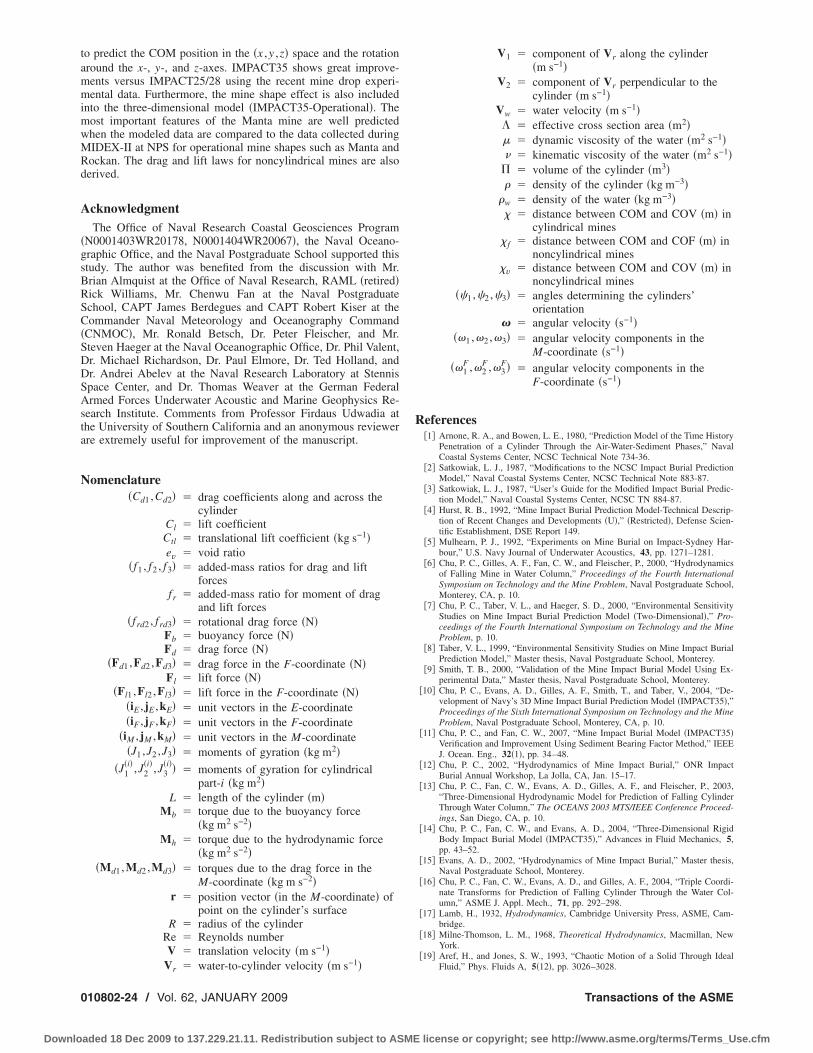
tammimwMRd
A
�gsBRSC�SDDSAsta
N
0
Downlo
o predict the COM position in the �x ,y ,z� space and the rotationround the x-, y-, and z-axes. IMPACT35 shows great improve-ents versus IMPACT25/28 using the recent mine drop experi-ental data. Furthermore, the mine shape effect is also included
nto the three-dimensional model �IMPACT35-Operational�. Theost important features of the Manta mine are well predictedhen the modeled data are compared to the data collected duringIDEX-II at NPS for operational mine shapes such as Manta andockan. The drag and lift laws for noncylindrical mines are alsoerived.
cknowledgmentThe Office of Naval Research Coastal Geosciences Program
N0001403WR20178, N0001404WR20067�, the Naval Oceano-raphic Office, and the Naval Postgraduate School supported thistudy. The author was benefited from the discussion with Mr.rian Almquist at the Office of Naval Research, RAML �retired�ick Williams, Mr. Chenwu Fan at the Naval Postgraduatechool, CAPT James Berdegues and CAPT Robert Kiser at theommander Naval Meteorology and Oceanography Command
CNMOC�, Mr. Ronald Betsch, Dr. Peter Fleischer, and Mr.teven Haeger at the Naval Oceanographic Office, Dr. Phil Valent,r. Michael Richardson, Dr. Paul Elmore, Dr. Ted Holland, andr. Andrei Abelev at the Naval Research Laboratory at Stennispace Center, and Dr. Thomas Weaver at the German Federalrmed Forces Underwater Acoustic and Marine Geophysics Re-
earch Institute. Comments from Professor Firdaus Udwadia athe University of Southern California and an anonymous reviewerre extremely useful for improvement of the manuscript.
omenclature�Cd1 ,Cd2� � drag coefficients along and across the
cylinderCl � lift coefficientCtl � translational lift coefficient �kg s−1�ev � void ratio
�f1 , f2 , f3� � added-mass ratios for drag and liftforces
fr � added-mass ratio for moment of dragand lift forces
�frd2 , frd3� � rotational drag force �N�Fb � buoyancy force �N�Fd � drag force �N�
�Fd1 ,Fd2 ,Fd3� � drag force in the F-coordinate �N�Fl � lift force �N�
�Fl1 ,Fl2 ,Fl3� � lift force in the F-coordinate �N��iE , jE ,kE� � unit vectors in the E-coordinate�iF , jF ,kF� � unit vectors in the F-coordinate
�iM , jM ,kM� � unit vectors in the M-coordinate�J1 ,J2 ,J3� � moments of gyration �kg m2�
�J1�i� ,J2
�i� ,J3�i�� � moments of gyration for cylindrical
part-i �kg m2�L � length of the cylinder �m�
Mb � torque due to the buoyancy force�kg m2 s−2�
Mh � torque due to the hydrodynamic force�kg m2 s−2�
�Md1 ,Md2 ,Md3� � torques due to the drag force in theM-coordinate �kg m s−2�
r � position vector �in the M-coordinate� ofpoint on the cylinder’s surface
R � radius of the cylinderRe � Reynolds numberV � translation velocity �m s−1�
−1
Vr � water-to-cylinder velocity �m s �10802-24 / Vol. 62, JANUARY 2009
aded 18 Dec 2009 to 137.229.21.11. Redistribution subject to ASME
V1 � component of Vr along the cylinder�m s−1�
V2 � component of Vr perpendicular to thecylinder �m s−1�
Vw � water velocity �m s−1�� � effective cross section area �m2�� � dynamic viscosity of the water �m2 s−1�� � kinematic viscosity of the water �m2 s−1�
� volume of the cylinder �m3�� � density of the cylinder �kg m−3�
�w � density of the water �kg m−3�� � distance between COM and COV �m� in
cylindrical mines� f � distance between COM and COF �m� in
noncylindrical mines�v � distance between COM and COV �m� in
noncylindrical mines��1 ,�2 ,�3� � angles determining the cylinders’
orientation� � angular velocity �s−1�
��1 ,�2 ,�3� � angular velocity components in theM-coordinate �s−1�
��1F ,�2
F ,�3F� � angular velocity components in the
F-coordinate �s−1�
References�1� Arnone, R. A., and Bowen, L. E., 1980, “Prediction Model of the Time History
Penetration of a Cylinder Through the Air-Water-Sediment Phases,” NavalCoastal Systems Center, NCSC Technical Note 734-36.
�2� Satkowiak, L. J., 1987, “Modifications to the NCSC Impact Burial PredictionModel,” Naval Coastal Systems Center, NCSC Technical Note 883-87.
�3� Satkowiak, L. J., 1987, “User’s Guide for the Modified Impact Burial Predic-tion Model,” Naval Coastal Systems Center, NCSC TN 884-87.
�4� Hurst, R. B., 1992, “Mine Impact Burial Prediction Model-Technical Descrip-tion of Recent Changes and Developments �U�,” �Restricted�, Defense Scien-tific Establishment, DSE Report 149.
�5� Mulhearn, P. J., 1992, “Experiments on Mine Burial on Impact-Sydney Har-bour,” U.S. Navy Journal of Underwater Acoustics, 43, pp. 1271–1281.
�6� Chu, P. C., Gilles, A. F., Fan, C. W., and Fleischer, P., 2000, “Hydrodynamicsof Falling Mine in Water Column,” Proceedings of the Fourth InternationalSymposium on Technology and the Mine Problem, Naval Postgraduate School,Monterey, CA, p. 10.
�7� Chu, P. C., Taber, V. L., and Haeger, S. D., 2000, “Environmental SensitivityStudies on Mine Impact Burial Prediction Model �Two-Dimensional�,” Pro-ceedings of the Fourth International Symposium on Technology and the MineProblem, p. 10.
�8� Taber, V. L., 1999, “Environmental Sensitivity Studies on Mine Impact BurialPrediction Model,” Master thesis, Naval Postgraduate School, Monterey.
�9� Smith, T. B., 2000, “Validation of the Mine Impact Burial Model Using Ex-perimental Data,” Master thesis, Naval Postgraduate School, Monterey.
�10� Chu, P. C., Evans, A. D., Gilles, A. F., Smith, T., and Taber, V., 2004, “De-velopment of Navy’s 3D Mine Impact Burial Prediction Model �IMPACT35�,”Proceedings of the Sixth International Symposium on Technology and the MineProblem, Naval Postgraduate School, Monterey, CA, p. 10.
�11� Chu, P. C., and Fan, C. W., 2007, “Mine Impact Burial Model �IMPACT35�Verification and Improvement Using Sediment Bearing Factor Method,” IEEEJ. Ocean. Eng., 32�1�, pp. 34–48.
�12� Chu, P. C., 2002, “Hydrodynamics of Mine Impact Burial,” ONR ImpactBurial Annual Workshop, La Jolla, CA, Jan. 15–17.
�13� Chu, P. C., Fan, C. W., Evans, A. D., Gilles, A. F., and Fleischer, P., 2003,“Three-Dimensional Hydrodynamic Model for Prediction of Falling CylinderThrough Water Column,” The OCEANS 2003 MTS/IEEE Conference Proceed-ings, San Diego, CA, p. 10.
�14� Chu, P. C., Fan, C. W., and Evans, A. D., 2004, “Three-Dimensional RigidBody Impact Burial Model �IMPACT35�,” Advances in Fluid Mechanics, 5,pp. 43–52.
�15� Evans, A. D., 2002, “Hydrodynamics of Mine Impact Burial,” Master thesis,Naval Postgraduate School, Monterey.
�16� Chu, P. C., Fan, C. W., Evans, A. D., and Gilles, A. F., 2004, “Triple Coordi-nate Transforms for Prediction of Falling Cylinder Through the Water Col-umn,” ASME J. Appl. Mech., 71, pp. 292–298.
�17� Lamb, H., 1932, Hydrodynamics, Cambridge University Press, ASME, Cam-bridge.
�18� Milne-Thomson, L. M., 1968, Theoretical Hydrodynamics, Macmillan, NewYork.
�19� Aref, H., and Jones, S. W., 1993, “Chaotic Motion of a Solid Through Ideal
Fluid,” Phys. Fluids A, 5�12�, pp. 3026–3028.Transactions of the ASME
license or copyright; see http://www.asme.org/terms/Terms_Use.cfm

A
Downlo
�20� Aref, H., and Jones, S. W., 1994, “Motion of a Solid Body Through an IdealFluid,” College of Engineering, University of Illinois at Urbana-Champaign,Report No. 772.
�21� Holmes, P., Jenkins, J., and Leonard, N. E., 1998, “Dynamics of the KirchhoffEquations I: Coincident Centers of Gravity and Buoyancy,” Physica D,118�3–4�, pp. 311–342.
�22� Field, S. B., Klaus, M., Moore, M. G., and Nori, F., 1997, “Chaotic Dynamicsof Falling Disks,” Nature �London�, 388�6639�, pp. 252–254.
�23� Mahadevan, L., Ryu, W. S., and Aravinthan, D. T. S., 1999, “Tumbling Cards,”Phys. Fluids, 11�1�, 1–3.
�24� Kochin, N. E., Kibel, I. A., Roze, N. V., 1964, Theoretical Hydromechanics,Intersciences, New York.
�25� Kozlov, V. V., 1989, “Heavy Rigid Body Falling in an Ideal Fluid,” Izv ANSSSR, Mekhanika Tverdogo Tela, 24�5�, pp. 10–17.
�26� Satkowiak, L. J., 1988, “Modified NCSC Impact Burial Prediction Model withComparisons to Mine Drop Tests,” Naval Coastal Systems Center, NCSC TN486-88.
�27� Chu, P. C., 2002, “Ensemble Mine Impact Burial Prediction,” ONR ImpactBurial Modeling Workshop, Phoenix, AZ, March 5–7.
�28� Chu, P. C., Taber, V. L., and Haeger, S. D., 2000, “A Mine Impact BurialModel Sensitivity Study,” Naval Postgraduate School, NPS-IJWA-00-003.
�29� Stanley, E. M., 1969, “Viscosity of Sea Water at Moderate Temperatures andPressures,” J. Geophys. Res., 74, 3415–3420.
�30� Krone, R. B., “A Study of Rheological Properties of Estuarine Sediments,”Technical Bulletin No. 7.
�31� Chu, P. C., Smith, T. B., and Haeger, S. D., 2001, “Mine Impact Burial Pre-diction Experiment,” Naval Postgraduate School, NPS-IJWA-01-007.
�32� Chu, P. C., Smith, T. B., and Haeger, S. D., 2002, “Mine Impact Burial Pre-diction,” Proceedings of the Fourth International Symposium on Technologyand the Mine Problem, Naval Postgraduate School, Monterey, CA, p. 10.
�33� Crowe, C. T., Roberson, J. A., and Elger, D. F., 2001, “Engineering FluidMechanics,” 7th ed., Wiley, New York, pp. 1–714.
�34� Chu, P. C., Gilles, A. F., Fan, C. W., Lan, J., and Fleischer, P., 2002, “Hydro-dynamics of Falling Cylinder in Water Column,” Advances in Fluid Mechan-ics, 4, pp. 163–181.
�35� Chu, P. C., and Fan, C. W., 2005, “Pseudo-Cylinder Parameterization for MineImpact Burial Prediction,” ASME J. Fluids Eng., 127, pp. 1515–1520.
�36� Chu, P. C., and Fan, C. W., 2006, “Prediction of Falling Cylinder ThroughAir-Water-Sediment Columns,” ASME J. Appl. Mech., 73, pp. 300–314.
�37� Chu, P. C., and Ray, G., 2006, “Prediction of High Speed Rigid Body Maneu-
pplied Mechanics Reviews
aded 18 Dec 2009 to 137.229.21.11. Redistribution subject to ASME
vering in Air-Water-Sediment Column,” Advances in Fluid Mechanics, 6, pp.123–132.
�38� Chu, P. C., Ray, G., Fleischer, P., and Gefken, P., 2006, “Development ofThree Dimensional Bomb Maneuvering Model,” Proceedings of the SeventhMonterey International Symposium on Technology and Mine Problems, NavalPostgraduate School, Monterey, CA, p. 10.
�39� Rouse, H., 2006, Fluid Mechanics for Hydraulic Engineers, 1st ed., McGraw-Hill Book, New York, p. 422.
�40� Von Mises, R., 1959, Theory of Flight, Dover, New York, pp. 564–585.�41� Sumer, B. M., and Fredsøe, J., 1997, Hydrodynamics Around Cylindrical
Structures, World Scientific, Singapore, p. 530.�42� White, F. M., 1974, Viscous Fluid Flow, McGraw-Hill Inc., New York, p. 712.�43� Hansen, N. E. O., Simonsen, B. C., and Sterndoff, M. J., 1994, “Soil Mechan-
ics of Ship Beaching,” Proceedings of 24th International Conference onCoastal Engineering, Kobe, Japan, p. 3030–3044.
�44� Aubeny, C. P., and Shi, H., 2007, “Effect of Rate-Dependent Soil Strength onCylinders Penetrating Into Soft Clay,” IEEE J. Ocean. Eng., 32�1�, pp. 49–56.
�45� Gilles, A. F., 2001, “Mine Drop Experiment,” Master thesis, Naval Postgradu-ate School, Monterey.
�46� Chu, P. C., Gilles, A. F., and Fan, C. W., 2005, “Experiment of Falling Cylin-der Through the Water Column,” Exp. Therm. Fluid Sci., 29, pp. 555–568.
�47� Abelev, A. V., Valent, P. J., and Holland, K. T., 2007, “Behavior of a LargeCylinder in Free Fall Through Water,” IEEE J. Ocean. Eng., 32�1�, pp. 10–20.
�48� Holland, K. T., Green, A. W., Abelev, A., and Valent, P. J., 2004, “Parameter-ization of the In-Water Motions of Falling Cylinders Using High-SpeedVideo,” Exp. Therm. Fluid Sci., 37, pp. 690–770.
�49� Elmore, P. A., Wilkens, R., Weaver, T., and Richardson, M. D., 2005, “IM-PACT 28 and 35 Simulations of 2003 Baltic Sea Cruise: Model Results andComparison with Data,” Fifth Annual ONR Workshop on Mine Burial Predic-tion, Kona, HI, Jan. 31–Feb. 2.
�50� Elmore, P. A., Richardson, M. D., and Wilkens, R. H., 2007, “Exercising aDeterministic Mine Burial Prediction System for Impact and Scour Burial forOperational Navy Use,” IEEE J. Ocean. Eng., 32�1�, pp. 273–283.
�51� Chu, P. C., Allen, C. R., and Fleischer, P., 2006, “Non-Cylindrical Mine Im-pact Experiment,” Proceedings of the Seventh Monterey International Sympo-sium on Technology and Mine Problems, Naval Postgraduate School,Monterey, CA, p. 10.
�52� Allen, C. R., 2006, “Mine Drop Experiment II with Operational Mine Shapes
�MIDEX-II�,” Master thesis, Naval Postgraduate School, Monterey.Dr. Peter Chu is a Professor of Oceanography and head of the Naval Ocean Analysis and Prediction(NOAP) Laboratory at the Naval Postgraduate School. His research interests include ocean analysis andprediction, coastal modeling, littoral zone oceanography for mine warfare, mine impact burial prediction,mine acoustic detection, and satellite data assimilation for undersea warfare. He received his Ph.D. inGeophysical Fluid Dynamics from the University of Chicago in 1985.
JANUARY 2009, Vol. 62 / 010802-25
license or copyright; see http://www.asme.org/terms/Terms_Use.cfm