minecraft to c for the raspberry pi - uva · minecraft to c for the raspberry pi tom peerdeman ......
TRANSCRIPT

Bachelor Informatica
Minecraft to Cfor the Raspberry Pi
Tom PeerdemanStudent nr. 10266186
July 1, 2014
Supervisor(s): Raphael ’kena’ Poss (UvA)
Signed: Raphael ’kena’ Poss (UvA)
Informatica—
Universiteit
vanAmst
erdam

2

Abstract
In modern day education, studying logic and digital circuits is a essential part of beta studies.Minecraft appears to be an ideal tool for learning these subjects. Minecraft has redstone,a feature that enables the creation of circuits very similar to traditional digital logic. Thedownside is that executing the redstone circuits is very slow. In this thesis we will speedup the simulation of redstone by pulling it out of the Minecraft environment. We will thentransform these circuits to logic equivalents to be able to simulate them. As an extensionwe will add a real life input/output device that can also interact with our logic circuits.
3
Contents
1 Introduction 51.1 Motivation . . . . . . . . . . . . . . . . . . . . . . . . . . . . . . . . . . . . . . . 61.2 The project . . . . . . . . . . . . . . . . . . . . . . . . . . . . . . . . . . . . . . . 7
2 Overview of the redstone components 82.1 Input components . . . . . . . . . . . . . . . . . . . . . . . . . . . . . . . . . . . 82.2 Output components . . . . . . . . . . . . . . . . . . . . . . . . . . . . . . . . . . 92.3 Components from the Raspberry Pi . . . . . . . . . . . . . . . . . . . . . . . . . 92.4 Remaining components . . . . . . . . . . . . . . . . . . . . . . . . . . . . . . . . . 102.5 Powering other blocks . . . . . . . . . . . . . . . . . . . . . . . . . . . . . . . . . 122.6 Ignored components and functions . . . . . . . . . . . . . . . . . . . . . . . . . . 12
3 Detecting redstone circuits 143.1 Defining the detection area . . . . . . . . . . . . . . . . . . . . . . . . . . . . . . 153.2 First attempt: path finding . . . . . . . . . . . . . . . . . . . . . . . . . . . . . . 153.3 Iterative neighbour algorithm . . . . . . . . . . . . . . . . . . . . . . . . . . . . . 163.4 Prioritized neighbour algorithm . . . . . . . . . . . . . . . . . . . . . . . . . . . . 193.5 Complexity of the prioritized neighbour algorithm . . . . . . . . . . . . . . . . . 20
4 Transforming redstone components to logic components 234.1 Transforming redstone wires . . . . . . . . . . . . . . . . . . . . . . . . . . . . . . 234.2 Transforming powered blocks . . . . . . . . . . . . . . . . . . . . . . . . . . . . . 254.3 Cleaning unused components . . . . . . . . . . . . . . . . . . . . . . . . . . . . . 254.4 Complexity of the transformation . . . . . . . . . . . . . . . . . . . . . . . . . . . 26
5 Implementing the simulator 275.1 Intermediate representation . . . . . . . . . . . . . . . . . . . . . . . . . . . . . . 285.2 Implementation . . . . . . . . . . . . . . . . . . . . . . . . . . . . . . . . . . . . . 29
5.2.1 Programming language . . . . . . . . . . . . . . . . . . . . . . . . . . . . 295.2.2 Interacting with the simulator . . . . . . . . . . . . . . . . . . . . . . . . . 295.2.3 Implementation of the simulator itself . . . . . . . . . . . . . . . . . . . . 31
5.3 Testing the simulator . . . . . . . . . . . . . . . . . . . . . . . . . . . . . . . . . . 32
6 Integrating the Raspberry Pi 34
7 Open problems 377.1 Visualizing the graphs . . . . . . . . . . . . . . . . . . . . . . . . . . . . . . . . . 377.2 Detecting the circuits . . . . . . . . . . . . . . . . . . . . . . . . . . . . . . . . . 387.3 Transforming the circuits . . . . . . . . . . . . . . . . . . . . . . . . . . . . . . . 39
8 Conclusions 40
4

CHAPTER 1
Introduction
Minecraft is a popular open world 3-D game, with over 15 million users, and is increasing withover 15 thousand new copies bought every day [4]. In Minecraft the player is placed into a worldcomposed uniquely of textured cubes. These cubes are called blocks in the Minecraft world. Anexample of terrain generation using these blocks is given in figure 1.1a. The player can interactwith this world by breaking and placing these blocks, and thus removing them from or insertingthem into the world. A lot of different types of blocks exist. All these types have differenttextures and different properties, like the time the player has to click on the block to break it.When the player breaks a block, depending on the block type, often an item version of the blockcan be picked up by the player. Using these items the player can craft new items. Some of theseitems can be used as armour, tools or light sources, others can be placed again as blocks. Acouple of game modes exist in Minecraft: First we have the creative game mode, in this gametype a player can spawn in blocks, and instantly break them. The next game mode is survival.In this game mode the player has to survive hordes of enemies that spawn during the Minecraftnight. The player can hide from them by building a safe area [17, 18]. For example see figure1.1b.
(a) Terrain generation using blocks. (b) The player can protect itself by building shelter.
Figure 1.1: Ingame screenshots of Minecraft.
Some research has been done to utilize Minecraft in education. For example in an article ofDaniel Short, from the university of Liverpool, he states that the Minecraft world resembles thereal world in a couple of aspects. These aspects could help the teacher, by using Minecraft as a
5
addition to the usual teaching methods [14].Another article from Jeffrey Brand and Shelley Kinash from the Bond university of Australiastate that Minecraft can be used in education in two ways. The first way is to provide an alter-native informal learning environment. The second way is as a simulation environment, similarto the article of Daniel Short described [6].
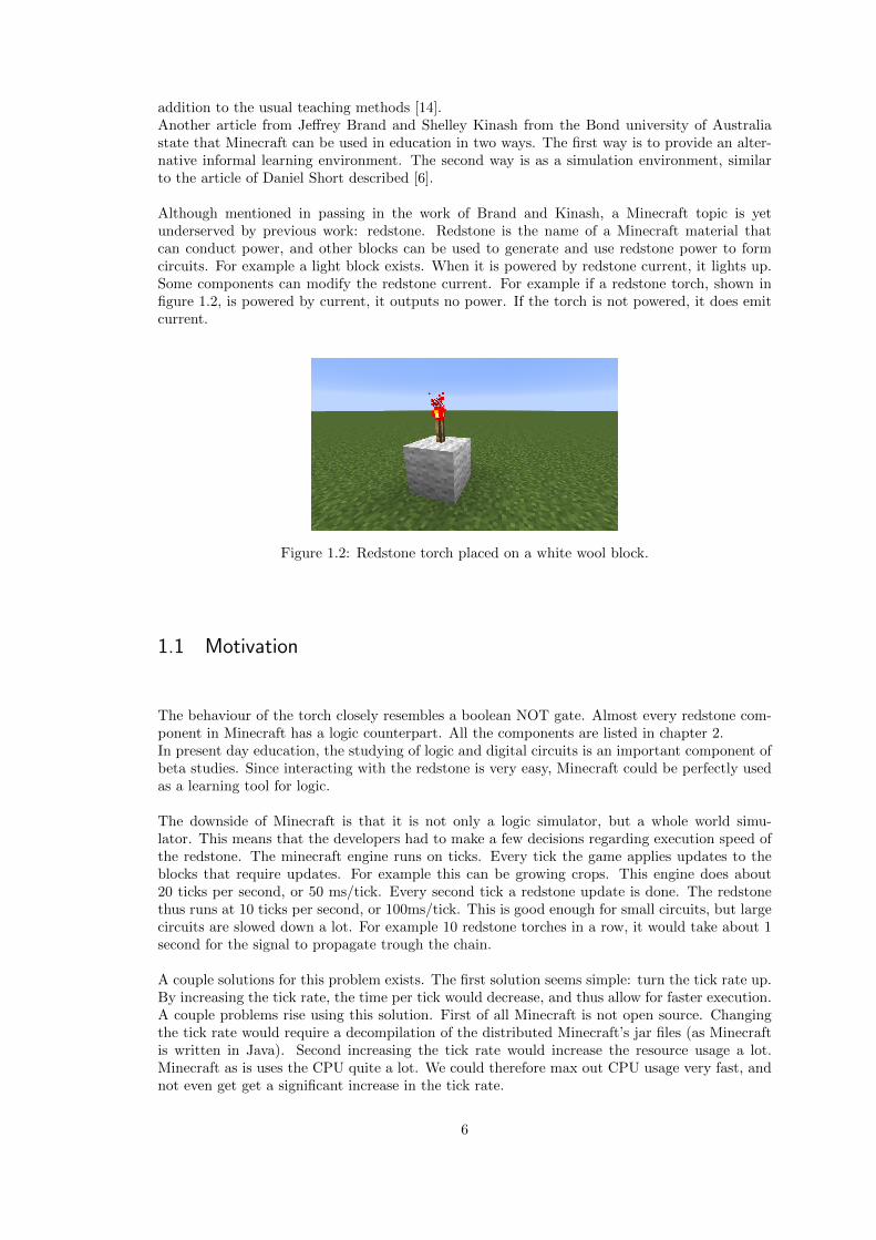
Although mentioned in passing in the work of Brand and Kinash, a Minecraft topic is yetunderserved by previous work: redstone. Redstone is the name of a Minecraft material thatcan conduct power, and other blocks can be used to generate and use redstone power to formcircuits. For example a light block exists. When it is powered by redstone current, it lights up.Some components can modify the redstone current. For example if a redstone torch, shown infigure 1.2, is powered by current, it outputs no power. If the torch is not powered, it does emitcurrent.
Figure 1.2: Redstone torch placed on a white wool block.
1.1 Motivation
The behaviour of the torch closely resembles a boolean NOT gate. Almost every redstone com-ponent in Minecraft has a logic counterpart. All the components are listed in chapter 2.In present day education, the studying of logic and digital circuits is an important component ofbeta studies. Since interacting with the redstone is very easy, Minecraft could be perfectly usedas a learning tool for logic.
The downside of Minecraft is that it is not only a logic simulator, but a whole world simu-lator. This means that the developers had to make a few decisions regarding execution speed ofthe redstone. The minecraft engine runs on ticks. Every tick the game applies updates to theblocks that require updates. For example this can be growing crops. This engine does about20 ticks per second, or 50 ms/tick. Every second tick a redstone update is done. The redstonethus runs at 10 ticks per second, or 100ms/tick. This is good enough for small circuits, but largecircuits are slowed down a lot. For example 10 redstone torches in a row, it would take about 1second for the signal to propagate trough the chain.
A couple solutions for this problem exists. The first solution seems simple: turn the tick rate up.By increasing the tick rate, the time per tick would decrease, and thus allow for faster execution.A couple problems rise using this solution. First of all Minecraft is not open source. Changingthe tick rate would require a decompilation of the distributed Minecraft’s jar files (as Minecraftis written in Java). Second increasing the tick rate would increase the resource usage a lot.Minecraft as is uses the CPU quite a lot. We could therefore max out CPU usage very fast, andnot even get get a significant increase in the tick rate.
6
1.2 The project
The solution of the speed problem we will be using is similar to increasing the tick rate. Ifwe would pull the redstone simulation out of minecraft, we could create a much more efficientsimulator. This simulator does not have to simulate the whole Minecraft game-play, and canthus run on a much higher tick-rate.Why stop there? As said before, redstone resembles a lot to logic circuits. Simulating logiccircuits is a lot easier. Also these logic circuits can be used for things outside the scope of thisproject. For example, these circuits could be transformed to VHDL [20].
Our main goal is education, so how can make the simulation more interesting? If we wouldbe able to extend our simulation by using real life components, like switches and lights, it wouldbe much more interesting. So now two questions remains: How can we efficiently make use ofMinecraft’s redstone circuitry to define logic circuits? And how can we extend this simulationto utilize real life components?
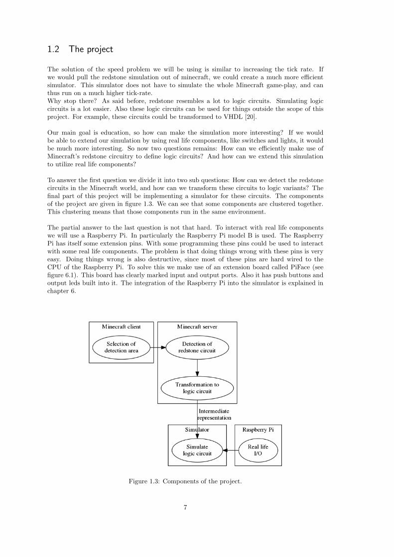
To answer the first question we divide it into two sub questions: How can we detect the redstonecircuits in the Minecraft world, and how can we transform these circuits to logic variants? Thefinal part of this project will be implementing a simulator for these circuits. The componentsof the project are given in figure 1.3. We can see that some components are clustered together.This clustering means that those components run in the same environment.
The partial answer to the last question is not that hard. To interact with real life componentswe will use a Raspberry Pi. In particularly the Raspberry Pi model B is used. The RaspberryPi has itself some extension pins. With some programming these pins could be used to interactwith some real life components. The problem is that doing things wrong with these pins is veryeasy. Doing things wrong is also destructive, since most of these pins are hard wired to theCPU of the Raspberry Pi. To solve this we make use of an extension board called PiFace (seefigure 6.1). This board has clearly marked input and output ports. Also it has push buttons andoutput leds built into it. The integration of the Raspberry Pi into the simulator is explained inchapter 6.
Figure 1.3: Components of the project.
7

CHAPTER 2
Overview of the redstone components
To be able to define logic circuits with redstone, we first have to understand all the redstonecomponents Minecraft has to offer. We can put these components in three categories. We havethe input components. These components can provide power, and ignore any power going in.The second category are the output components. These components take power as an input anddo something with it. For example these components can provide light, sound or mechanicalmovement (in the Minecraft world of course). The last components are the remaining compo-nents. These components take power as input, transform it by a function and then output thenew power.
As explained in chapter 1 the Minecraft redstone engine runs using ticks. The componentsfrom the first two categories however have no tick delay in their behaviour.Some components from the last category however do have a delay. Most of these componentshave a delay of one tick. The maximum delay of an component is 4 ticks.
Every redstone component however has a common feature. Every component can use or producepower. This power is represented using a power level. This level is stored in 4 bits, which meansthe power level can be 0 to a maximum of 15. In the Minecraft world a power level of 0 meansno power at all. A power level of 15 corresponds to power of maximum strength. The powerlevel 0 is always present in the world. This means that a component from the last two categoriesthat has no input connected, has an input of power level 0.
2.1 Input components
One of the simplest components has to be the redstone block. This block, despite is simplicity,was added in one of the latest updates dated March 7, 2013. The behaviour of this block is equalto the logical true. This block always outputs a signal value of 15.
The next component is the lever, or switch. This component has two states. In the first,default, state the component does not output any power. This is equal to outputting a powerlevel 0. In the second state, the component outputs the maximum power level 15. The user canswitch between these states by clicking on the component in the Minecraft world.
Very similar to the switch is the button. This component also has two states. When the userclicks on the button, the state is flipped to the on state. The user cannot flip the state back.The button flips itself back after 10 to 15 seconds, depending on the type of the button.
The next component, the pressure plate, has a few variations. The normal pressure plate’s
8

behaviour is quite similar to that of the switch and the button. If an entity, either a player, anitem or a monster, is on the pressure plate, the state is on. Otherwise the state is off.
The other two variants do not have the two states. The iron and gold pressure plate outputa power level which is linear to the amount of entities on it, capped at the maximum power level.The gold pressure plate increases the power level by one for each entity on it. The iron pressureplate increases the power level by one for each 10 entities on it.
Another component that can output a varying power level is the daylight sensor. The day-light sensor outputs a power level which corresponds to the height of the sun in the Minecraftworld. If the sun is at its highest point (midday) the power level outputted is 15. At midnightthe power level outputted is 0.
2.2 Output components
The first output component is the redstone lamp. This component will light up, if an input powerwith a power level greater than 0 is provided. The light this lamp provides cannot influence thedaylight sensor.
The next component produces sound. This block is called the note block. The note the blockplays can be adjusted by the player. The instrument used for playing the note is determined bythe block the note block is placed on. When the power level changes from 0 to any value above0 the note is played.
The last output component is the piston. In Minecraft the piston can move up to 12 blocksfor exactly one block in the direction the piston is facing. When the input power of the pistonis greater than 0, the piston is extended. When the powers is equal to 0 the piston is retracted.Since this block can move other blocks, it is possible that the layout, or the power levels of thecircuit change, depending on the state of the piston. For example a piston can move a redstoneblock next to a wire. This changes the state of the circuit, since the wire is now powered. Becausethis can change the circuits in a lot of ways, this feature is ignored in the detection. The pistonis seen purely as output component, that cannot change the state of the circuit.
2.3 Components from the Raspberry Pi
While listing the components of Minecraft’s redstone, we might forget the second component ofthis project. Since we want to interact with the Raspberry Pi, we have to list two more compo-nents. These components fit perfect in the two above categories.
The first component is the digital input from the Raspberry Pi. This input acts like any otherinput in Minecraft. When the corresponding gate is powered on the Raspberry Pi, the compo-nent in Minecraft should output the maximum power level. If it is not powered on the board,the outputted power level is 0.
The output component from the Raspberry Pi acts the same as any of the outputs from Minecraft.When in Minecraft the component is powered with a power level greater than 0, the output onthe Raspberry Pi is also powered. If the component is not powered, neither is the output on theboard. Note that the output on the board is digital, so it is either fully powered or not at all.A variable power output on the board could be scaled to the power level provided in Minecraft.However a different expansion board would be required for this feature. This could also applyto the input of course.
9

2.4 Remaining components
The remaining components all take at least one input. The output values are functions of theinput values. The best way to describe these functions is using pseudo code. In the next descrip-tions the input values are given using a vector called input.
The first component is the redstone torch. The redstone torch has exactly one input. Theinput is the block the torch is attached to. The behaviour of this component is very similar toa logic NOT gate. The function describing the exact behaviour is given in listing 2.1. Note thatwithout any input, or an input of power level 0, the output is always the maximum power level.In these cases the redstone torch acts like it is an input component. This component has a tickdelay of one tick.
Listing 2.1: Redstone behaviour for the redstone torch.
1 function redstoneTorch(inputs) {2 if(inputs.size >= 1 && inputs[0] > 0) {3 return 0;4 }5 return 15;6 }
As said before some components have delays of more than one tick. The redstone repeater is oneof them. The redstone repeater has a variable delay of 1 to a maximum of 4 ticks. The nameof this component somewhat reveals its behavior. When a signal of level 1 or greater is applied,the components repeats this signal by outputting the maximum signal level, see listing 2.2. Thiscomponent only does this in one direction, thus making it act like a diode.The input and output of the repeater are determined by the placing of the block. The repeateralways is placed horizontally. This allows for four different placings. With every placing the backis always designated as the input and the front as output.
Listing 2.2: Redstone behaviour for the redstone repeater.
1 function redstoneRepeater(inputs) {2 if(inputs.size >= 1 && inputs[0] > 0) {3 return 15;4 }5 return 0;6 }
These two components have common that they output a full signal or no signal at all, the nextcomponent can output a varying signal level. The component mentioned is called a redstonecomparator. This block is placed in the same way as the repeater. The only difference is thatan additional input is defined by power going into the sides. We will call this input input B. Wewill call the original input from the back input A. Note that the block has two sides, but onlyone extra input. When both sides are connected, the input value is assumed to be the maximumsignal level of both sides.The separating of the two inputs becomes important when looking at the behaviour. The redstonecomparator has two modes. The first mode, called compare, is listed in listing 2.3. The secondmode, called subtract, is listed in listing 2.4. In these listings the inputs are not given by theinputs vector, since we want to distinguish input A and B. If one of the inputs were to be notconnected, the corresponding input is equal to 0.The compare mode basically compares the signal level from input A with the level from input B.If A exceeds B then A is outputted. Otherwise a power level of 0 is outputted. The subtractionmode does as it says, it outputs a signal level A-B. This component has a one tick delay, nomatter what the mode is.
10

Listing 2.3: Redstone behaviour for the redstone comparator in compare mode.
1 function redstoneComparator compare(inputA, inputB) {2 if(inputA > inputB) {3 return inputA;4 }5 return 0;6 }
Listing 2.4: Redstone behaviour for the redstone comparator in subtract mode.
1 function redstoneComparator subtract(inputA, inputB) {2 if(inputA > inputB) {3 return inputA − inputB;4 }5 return 0;6 }
The final component Is probably one of the most important ones. This component is called theredstone wire. This component is used to connect all the other components to each other. Theredstone wire, also called redstone dust, is placed horizontally like the repeater and comparator.However the redstone wire has no facing initially. When two wires are placed next to eachother, or the wire connects to a component, its facing changes. The wire will bend towardsthe component it connected to. This creates either a line or a intersection. An example of thisbehaviour can be seen in figure 3.1.A special feature of the redstone wire is its connecting behaviour in the vertical diagonal direction.When a redstone wire is on top of a block it can connect to a redstone wire below it and exact1 in the x or z direction away from it. However this can only happen if no block is blockingthe vertical wire. This behaviour is shown in figure 2.1. In this figure we can see the wire isplaced on top of the green and white blocks, and are being powered by a redstone block. Insub figure 2.1a we can see that the wires on top of the white blocks connect to the wires on thegreen blocks. These wires are therefore also receiving power. In sub figure 2.1b the connectionis blocked by the yellow block, now the connection is broken the wires on the white blocks areno longer powered. This is visually indicated by the darker red colour of the wire. An exceptionto this rule is if the block blocking the vertical wire is a non opaque block, like glass or slabs,when this happens the wire can connect.
(a) A wire can connect in the vertical diagonaldirection.
(b) A wire cannot connect in the vertical diagonaldirection, if it’s blocked by an opaque block.
Figure 2.1
The behaviour of the power levels is a bit strange. The behaviour is listed in listing 2.5. Thiscomponent itself does nothing with the power level. This means that the output power is equalto the input power. It is however possible that multiple components connect as input for thewire. The output signal level is therefore the maximum of the input signal levels. The strangepart kicks in when a redstone wire is connected to another redstone wire. When this happensthe signal level is lowered by one, to a minimum of 0 on the edge of the wire component to the
11

other wire component. For example a redstone wire is connected to another redstone wire anda lamp. When this redstone wire is powered by a signal level of 15, it transmits this signal levelto the lamp. However on the edge of the wires the signal level is lowered by one. This meansthat the other wire gets an input signal of level 14. This means that the output value can bedifferent for each output connected to a wire. So unlike the other components, who have oneoutput value, a wire has to calculate the output value for each output it has.The redstone wire has no delay tick. This means that a line of redstone can be all activated inone tick.
Listing 2.5: Redstone behaviour for the redstone wire.
1 function redstoneWire(inputs, outputType) {2 if(inputs.size > 0) {3 output = max(inputs)4 } else {5 output = 0;6 }7 if(outputType == Wire) {8 return output 1;9 } else {
10 return output;11 }12 }
2.5 Powering other blocks
Beside all the listed components there is one more important component. Any opaque block canbe powered by redstone. When powered this block also outputs this same signal level. Howeverblock are powered using a special mechanism. We introduce the high and low power. These twopower types are completely independent of the power level. The high power can have any powerlevel, and so can the low power. A block can be powered by a high and low power. The block willalso output this type of power. Depending on the type of power outputted, some componentsthat connect to the block are powered, and some are not. Any component that can be poweredby low power can also be powered by high power. A powered block cannot power another block.All the components and which power they can provide and use are listed in table 2.1.
Table 2.1: List of components and what type of power they can produce and use when connectedto a opaque block.
Component Can provide Can useAny input High None
Any output None LowRedstone torch Low Low
Redstone repeater High LowRedstone comparator High Low (only input A), None from block (only input B)
Redstone wire Low High, Low (when directly wired into the block)
2.6 Ignored components and functions
The list of output and input components is however not finished. Minecraft defines a lot morecomponents. However these components provide or use events generated by the minecraft worlditself. Since we cannot simulate these events, we do not have the Minecraft world simulated afterall, we cannot use them in this project. These components are:
12

• Door: Opens on a redstone signal.
• Dispenser: A block that can drop items into the world, this can also use a subset of items.For example a bucket will be emptied into the world.
• Dropper: Similar to the dispenser, however the items are not used.
• TNT: Ignites on a redstone signal.
• Hopper: This block can pick up items dropped on top of it. It will also transport the itemsto other hoppers or a chest. When powered the items will not be moved to another hopperor chest, and will thus stay inside the hopper.
• Command block: This block can execute a command when a redstone signal is applied.
• Powered rail: Minecraft has a rail system. This block accelerates any carts on top of itwhen powered. It decelerates them when not powered.
• Detector rail: This rail emits a redstone signal when a cart passes over it.
• Rail intersection: A rail that has more than 2 other rails connected to it can act as a switch.When a redstone signal is applied, the switch changes it state.
Note that the last three, the rail components can actually create some interesting circuits. Imple-menting this in the simulator however would require to implement the Minecraft rail simulation.This would require a lot of time, and of course break the fact that we want to define logic circuits.
Some components also have some other features that will not be used in this project. Anexample is the piston’s ability to change the circuit, as described above.Another example is the redstone comparator. This component can actually interact with theminecraft world. For example if on the side input A on the comparator a chest is placed, thecomparator will output a signal level linear to the percentage the chest is filled. The comparatorcan interact with many blocks this way. Implementing this would, again, require data from theMinecraft world itself. Since we do not have this data, like the percentage a chest is filled, atsimulation time, we cannot use these features.
The final feature could actually be implemented in the simulation. When a redstone repeater ispowered at one of it non input or output sides by another redstone repeater, it enters a lockingstate. When this locking state is active the repeater will save the output level it is currentlyoutputting. While the locking state is active this output will stay locked in this saved state.Even when the input signal is changed, the output stays the saved state.This feature is however quite unknown and underused by the Minecraft users. Implementingthis feature would require a lot of extra code, like separation of the inputs like the comparator.Therefore was chosen not to implement this feature.
13

CHAPTER 3
Detecting redstone circuits
One of the core components of this project is the actual detection of the circuits in the Minecraftworld. We want to achieve this by implementing an not too complicated algorithm. This algo-rithm should also run in reasonable time.
So how should we implement this? The first question would be; in what language should wewrite the algorithm? Since we want to run the algorithm as fast as possible the answer could beC or C++, however we forgot an important part of the detection. The detection requires accessto the Minecraft world data. A program created in C or C++ could read the save files in orderto load the Minecraft world. This however poses a problem: The data of Minecraft is savedautomatic at an fairly long interval of about 2-3 minutes. This would lead to the player havingto wait about 3 minutes after each change. This opposes the criteria of the algorithm runningin reasonable time. The solution is integrating the detection with the game itself. Minecraft hasa large community, that created modifications for the game. These modifications can enhanceMinecraft by adding new items, new blocks, increasing the performance, and many more otherfeatures. This community also created libraries to let users implement mods themselves, withouta lot of effort. We can implement such a mod to access the world data. Since Minecraft is writtenin Java, so are these modding libraries. It is possible to create a bridge between a C programand a Java program, however this is not an easy method. It is therefore the best solution tocreate the detection algorithm in Java.
The next question is what modding library to use? The Minecraft modding community ismostly split up into two groups. One the first side we have Bukkit [1]. Bukkit is an API, thisAPI is implemented by server implementations. This means that the Bukkit mods (or pluginsas they are called in the Bukkit universe) can only rely on the API and not rest of the serverenvironment. The Bukkit API is server side only.On the other hand we have the Forge modding library [3]. Forge is both server side and clientside. Forge extends the original Minecraft client and server to provide its modding capabilities.Since both client and server are modded we can add new block and item types into the game.The Bukkit API cannot do this because the client does not know this new items or blocks. Sincewe do want to add a new item the latter one is chosen.
Now the input of the algorithm is taken care of, we can focus on the output. We want the outputof the algorithm to be an accurate description of the circuit. The simplest way to determinethe output is to look at the circuits itself. Circuits are basically components with connectionsbetween these components. We can therefore describe a circuit best as a graph. To be precisethis graph would be a directed graph, since diodes can be part of the circuit. A diode onlytransmits power into one direction, this would result in a single directed edge.
Visualizing these graphs is important for the user to see what was detected, and of course for
14

debugging purposes. To visualize these graphs a tool set called Graphviz was used [2]. Graphvizincludes tools to generate images of graphs from a text representation of that graph. The moditself can generate these text files. The Java VM can then call the program from the Grahpviztool set to generate the graph after the detection (and transformation) is done.
3.1 Defining the detection area
We can imagine that the more blocks are searched the longer it takes to detect all the circuits.The Minecraft world is built using chunks. Chunks are sections of 16x16x128 blocks, where 128is the height in blocks, which is increased to 256 in the newest versions. In older versions ofMinecraft the world can contain about 2,147,483,647 chunks in each direction from the center.This gives about 1.8 × 10¹⁹ chunks, which totals to 6.0 × 10²³ blocks in the world [12]. Whilethe limit is decreased to about 30 million blocks in each direction for the newer versions, we canstill see that this is an absurd amount [19]. It is therefore not feasible to detect the circuits forthe complete world. Instead we can let the user define an area in which his circuit is defined.
A common used method for defining an area in Minecraft, is specifying two blocks. Thesetwo blocks represent two outer points of an rectangular box. We can then find the absolutecoordinates of the starting and ending block, which are not necessary the given two blocks, usingthe equations given in equation 3.1. In these equations the vectors ~x and ~y are the coordinatesof the two given blocks.
~start = [min(x1, y1) min(x2, y2) min(x3, y3)]~end = [max(x1, y1) max(x2, y2) max(x3, y3)]
(3.1)
Since we use Forge as the modding library we can simple create a new item to select these twoblocks. This item, called Detection area selector, can select blocks by left clicking on them. Thisitem can also start the detection by left clicking on air blocks.
3.2 First attempt: path finding
The first thing a user might notice is that the detection area is not used efficiently. Most ofthe circuits defined in Minecraft are not built to fit in a small space. This is mostly due tousers tending to built their circuits on ground level. This results in the defined detection areacontaining only a small portion of the actual components we want to detect. An algorithm thatsearches the complete detection area would therefore be very inefficient.
The solution to this problem is a path finding algorithm. This smart algorithm can use therules of Minecraft redstone. Since each component in the circuit is connected to other compo-nents in the circuit trough 0 or more other components, we can find the complete circuit whenone component of the circuit is found. We can do this by discovering the path to all the con-nected components.We can detect the first component by iterating trough all the blocks in the detection area. Onceone component is found, this iterating can be stopped. The remaining components can thenbe found by applying the connection rules of redstone to the found component. For example afound component is a redstone repeater. The rule for a redstone repeater is that it only con-nects to other components that lie in the direction the repeater is facing. If we search the directneighbours of this repeater in the direction the repeater is facing, we can detect the componentsthis repeater is connected to. If we repeat this with the newly found components, we can detectthe whole circuit.
15
This algorithm is however not suitable for the purpose of this project. Lets say that we de-fine multiple circuits in the detection area. This smart algorithm would stop after finding onecircuit. This is not the behaviour intended. If we would extend the path finding algorithm todetect multiple circuits, we would have to restart the iteration over the blocks in the detectionarea. This iteration would then skip the already detected components. This however would defythe purpose of creating the path finding algorithm, since we did not want to iterate over all theblocks in the first place. This gets even worse when we look at the properties of circuits. Bydefinition a circuit is a directed graph with one or more components. By this definition a singleredstone wire would suffice as a circuit. This means that every block in the detection area isa possible circuit. We can therefore conclude that a path finding algorithm will not work. Wealways have to check every block in the detection area. We can therefore replace the algorithmby a better one that also searches the complete area, but is more efficient.
3.3 Iterative neighbour algorithm
The next algorithm is designed for detecting multiple circuits. The algorithm is based on theidea of quick access to the already detected circuits. This quick access is implemented by a 3-Darray of mapping entries. Each mapping, if not empty, entry contains a node an a reference tothe graph containing this node. Each block in the detection area corresponds to one of thosemappings. The mapping entry can therefore be retrieved using the relative coordinates of theblock to the detection area. These relative coordinates can then be used to index an entryin the mapping array. The conversion from block coordinates to relative coordinates is statedin equations 3.2. In these equations the vector ~i represents the index in the 3-D array. Thevector ~start represents the starting block in world coordinates, as defined in equations 3.1. Thecoordinates of the block in world coordinates are represented by the vector ~l.
~i = ~l − ~start~l = ~i + ~start
(3.2)
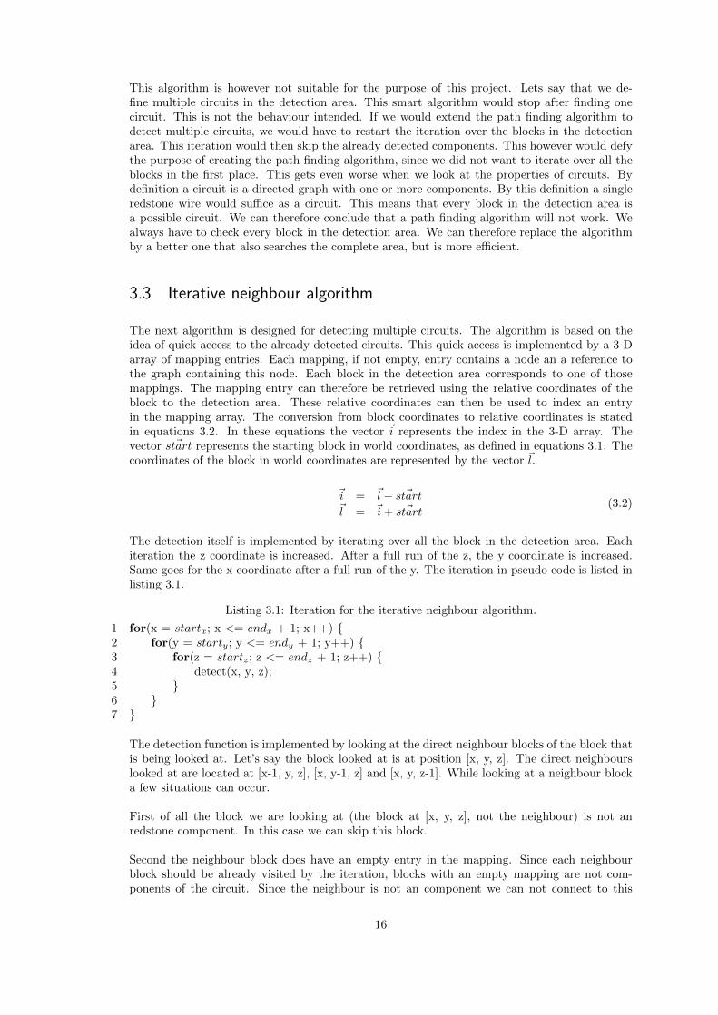
The detection itself is implemented by iterating over all the block in the detection area. Eachiteration the z coordinate is increased. After a full run of the z, the y coordinate is increased.Same goes for the x coordinate after a full run of the y. The iteration in pseudo code is listed inlisting 3.1.
Listing 3.1: Iteration for the iterative neighbour algorithm.
1 for(x = startx; x <= endx + 1; x++) {2 for(y = starty; y <= endy + 1; y++) {3 for(z = startz; z <= endz + 1; z++) {4 detect(x, y, z);5 }6 }7 }
The detection function is implemented by looking at the direct neighbour blocks of the block thatis being looked at. Let’s say the block looked at is at position [x, y, z]. The direct neighbourslooked at are located at [x-1, y, z], [x, y-1, z] and [x, y, z-1]. While looking at a neighbour blocka few situations can occur.
First of all the block we are looking at (the block at [x, y, z], not the neighbour) is not anredstone component. In this case we can skip this block.
Second the neighbour block does have an empty entry in the mapping. Since each neighbourblock should be already visited by the iteration, blocks with an empty mapping are not com-ponents of the circuit. Since the neighbour is not an component we can not connect to this
16

neighbour.
Third the neighbour block does have a non empty entry in the mapping, and the block itself (theblock at [x, y, z]) does have an empty mapping. In this case the neighbour block is a redstonecomponent. Since the component is already visited before, it should have a corresponding nodein a graph. Let’s say the current block should connect to the neighbour component following therules of redstone. In this case we can insert a new node for the current block into the graph ofthe neighbour. Also we insert this node and reference to the graph into the mapping.If however the component should not connect, then the current block probably is not part of thecircuit of the neighbour. We should therefore create a new graph, containing only a new nodefor the current block. This graph and node should also be inserted into the mapping entry forthis block.
Last if the neighbour block does not have an empty entry, and neither has the current block. Inthis case the current block is already connected to another neighbour, or created a single nodegraph. If the neighbour should connect with the current block, following the redstone rules, weshould merge the two graphs. This is done by transferring all the nodes of the graph with theleast amount of nodes into the other one. After the merge all the mapping entries are updated,so that each occurrence of one of the merged graphs is replaced by the new one. Note that it ispossible that the two graphs are actual the same one, since both neighbours can be in the samecircuit. In the case of merging a graph with itself, nothing is merged of course. After the mergethe mapping entry is filled, using the newly merged graph, and a new node, that is also insertedinto this graph.
It can occur that all the direct neighbours are not redstone components. If the current block is aredstone component however, we have to create a new graph. Again the mapping entry is filledusing this graph, and the node for this block.
This algorithm is listed in pseudo code in listing 3.2. The first case, the block is not a red-stone component, can be found on line 15. The second case, the neighbor is not a redstonecomponent, can be found on line 22. The final two cases can be found from line 27.
This algorithm however does have some problems detecting the redstone wires correctly. Firstof all, redstone wires can connect to other wires that are 1 block higher, the detection of thisconnection is however possible using an extended version of this algorithm. Lets imagine thefollowing situation. A redstone wire is located at location [1, 2, 3]. Another wire is located at [0,3, 3]. The wires should connect following the rules of redstone. If the iteration arrives at location[1, 2, 3] only the direct neighbours are checked, and thus the wire at [0, 3, 3] is not found as aconnected component. We cannot extend the definition of direct neighbours with [x-1, y+1, z]since the components at y+1 are not checked yet, and thus contain no mappings. However itdoes not matter if we detect component B if we check A or component A if we check B, thuswe can extend the definition with [x+1, y-1, z] for redstone wires. In the situation defined, thefollowing then happens: The search for block [1, 2, 3] results in no components connected to thewire. Then the iteration continues and finally searches the direct neighbours for the block [0, 3,3]. Since we extended this definition with the block [x+1, y-1, z], one of the neighbours checkedis the redstone wire at [1, 2, 3]. If we extend the definition by the blocks [x-1, y-1, z], [x, y-1,z-1] and [x, y-1, z+1] we can solve this problem for all directions.
17

(a) Single wire next to a blockdoes not connect.
(b) A line of wire into a blockdoes connect.
(c) A curved wire does not con-nect to a block.
Figure 3.1: Rules for redstone wires connecting to a block.
Listing 3.2: Detection function for the iterative neighbour algorithm.
1 function detect(x, y, z) {2 merge(x, y, z, (x − 1), y, z);3 merge(x, y, z, x, (y − 1), z);4 merge(x, y, z, x, y, (z − 1));56 if(emptyEntry(getEntry(x, y, z)) {7 g = new graph;8 n = new node(x, y, z);9 insert(g, n);
10 setEntry(x, y, z, g, n);11 }12 }1314 function merge(x, y, z, nx, ny, nz) {15 if(!redstoneComponent(x, y, z)) {16 return;17 }1819 nEntry = getEntry(nx, ny, nz);20 myEntry = getEntry(x, y, z);2122 if(emptyEntry(nEntry)) {23 g = new graph;24 n = new node(x, y, z);25 insert(g, n);26 setEntry(x, y, z, g, n);27 } else if(canConnect(x, y, z, nx, ny, nz) {28 g = getGraph(nEntry);29 n = new node(x, y, z);30 if(!emptyEntry(myEntry)) {31 g2 = getGraph(myEntry);32 g = mergeGraphs(g, g2);33 }34 insert(g, n);35 setEntry(x, y, z, g, n);36 }37 }
The next problem with the wire detection is the connection to blocks and output components.The redstone rules for wires connecting to blocks and lamps are shown in figure 3.1. The wireonly connects if it goes straight into the block. The wire only goes straight into the block if thereis a component on the other side of the wire in direction of the block, and if it does not connectto anything in the other two directions.
18

The algorithm cannot detect if the wire at [0, 0, 1] should connect to the block at [0, 0, 0].First the algorithm has to decide if there is an component on the other side wire in the directionof the block. This is not possible since the algorithm only checks the blocks [-1, 0, 0], [0, -1, 0]and [0, 0, 0]. This also applied for the check if the wire does not connect to any other componentsin the remaining directions.This cannot be solved easy. The only way to solve this is to delay the decision if a wire shouldconnect or not to a block after all its neighbours (neighbours in all directions) are checked.
3.4 Prioritized neighbour algorithm
The prioritized neighbour algorithm is an evolved version of the iterative neighbour algorithm.It is designed to fix the problems of the iterative neighbour algorithm. The basic idea is thatevery component is placed inside a category. Each category has a priority level. A component ina category should connect to any other components in category’s below or equal to its prioritylevel. This priority ensures that we do not have to create a connection rule for every componentto every component.
The algorithm itself operates in two phases. The first phase is creating an inventory of thecomponents in the detection area. The second phase is actually connecting these components toeach other, to create the circuit graphs.
The first phase works as follows. Each component has a category, which only contains thosecomponents. The algorithm iterates over all the blocks. For each component that is found thecoordinates of that block are placed in a list. This list is a part of the category. This meansthat every repeater is placed in the repeater category’s list, etc. The mapping from the iterativeneighbour algorithm is reused here. For each item found a new node is created. These nodehowever are not placed in any graph yet. The nodes are placed in the mapping array withoutthe reference to a graph.
The second phase loops over each item in the lists. The order in which the lists are loopedover is given by the category’s priority. The priority’s are high to low:
• Comparators
• Repeaters
• Inputs
• Redstone blocks
• Redstone torches
• Redstone wires
• Powered blocks
• Outputs
For each item the surrounding area of the block with the coordinates in the item is checked. Thecategory depicts what this surrounding area is. For example a redstone repeater has no use insearching the block below it, because it can never connect to that block following the redstonerules. If a component is found in the surrounding area the found component should connect tothe component. This connection should however only happen if the found component can connectfollowing the redstone rules, and the found component fits in a category lower or equal in priority.
When the connection is made, a couple of situations can occur:First of all both components do not have a graph element in the mapping. In this case a newgraph is created. The nodes of both components (coming from the mapping) are inserted into
19

this graph. The mapping of both components is then updated to contain a reference to this newgraph.The second situation is that one of the components has a graph entry, and the other one doesnot. In this case the component without a graph entry his node is placed in the graph of theother component. The mapping is then updated for the component without a graph.The final case is when both components already have a graph entry in their mapping entries.In this case the both graph’s should be merged. This is again done by placing all the nodes ofthe graph with the least nodes in the other graph. Again the mappings are updated to the newmerged graph.
3.5 Complexity of the prioritized neighbour algorithm
One can imagine that detecting larger circuits take longer time. The question is how muchlonger. Since the algorithm consists of two phases, we can determine the complexity of bothphases separate, to determine the complexity of the whole algorithm.
The first phase’s complexity is actually very simple. Lets say n is the number of blocks inthe detection area. This phase runs in linear time of this number of blocks. Or in the big Onotation: O(n). We can prove this by dissecting the algorithm in its components. The maincomponent is the iterating over all the blocks. The type of a block can be checked by correspond-ing Java class type, and thus in constant time. If a block is actually a redstone component weneed to find its corresponding category. This lookup can be (and is) implemented using a hashmap. Since the lookup of an component in a hash map is complexity O(1) so is the lookup ofthe category. The next part is inserting the component into the components list of the category.If we implement the list of components of the category using a linked list we can also achieveconstant time for this insertion. This is possible since the insertion of an element at the back of alinked list is complexity O(1). Since the body of the iteration is actually of constant complexitythis iteration executes n times a constant complexity. This results in the iteration, and thus thefirst phase of the algorithm having a complexity of O(n).
The second phase of the algorithm is however not so straightforward. Lets again consider theworst case. In the worst case the first phase of the algorithm has detected that every block in thedetection area is a component. This gives us n components to check for neighbour connections.The amount of neighbours checked for each component stays constant, so the actual detection ofneighbours is of complexity O(1) and thus not the problem. The first problem is the merging ofthe graph. Merging two graphs is implemented by inserting all the nodes of the smallest graphinto the largest. The worst case complexity for this merging is thus O(1/2n) = O(n). Since thisis done for every component, the second phase of the algorithm runs at least in O(n2).
The next problem lies in detecting the graph the neighbouring components are in. Since wehave the direct mapping of the component to the node and graph reference one might think thatthe graph lookup is constant. However this is not the case since we can merge two graphs. Theproblem is shown in figure 3.2. Entries 1 - 3 contain nodes that are in graph 1, entries 4 - 6contain nodes that are in graph 2. In the next step is discovered that the node in entry 3 and4 actually connect. This implies that graph 1 and 2 should be merged. This is done and thenodes of graph 2 are inserted into graph 1. However as can be seen in sub-figure 3.2b, the entriescontaining this nodes are not updated to the new graph. This also cannot be done easy, sincethere is no list of entries containing nodes in a specific graph.
The partial solution for this problem can be seen in sub-figure 3.3a. Instead of entries havinga pointer to the graph, they get a pointer to a wrapper object. This wrapper object then hasa pointer to the graph object. In this case when one entries graph should be changed, thiswill happen in the wrapper object the entry is pointing to. Then all the entries pointing tothis wrapper object have the new graph object. This principle works perfect for small circuits,
20
(a) Two graphs each have 3 mappings referenc-ing to them.
(b) The nodes in E3 and E4 connect, E5 andE6 are not updated.
Figure 3.2: Problem updating the graph reference of mapping entries.
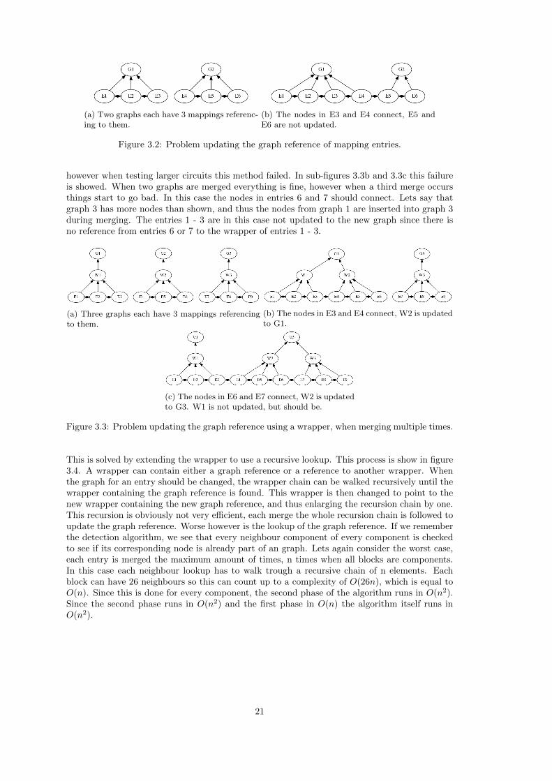
however when testing larger circuits this method failed. In sub-figures 3.3b and 3.3c this failureis showed. When two graphs are merged everything is fine, however when a third merge occursthings start to go bad. In this case the nodes in entries 6 and 7 should connect. Lets say thatgraph 3 has more nodes than shown, and thus the nodes from graph 1 are inserted into graph 3during merging. The entries 1 - 3 are in this case not updated to the new graph since there isno reference from entries 6 or 7 to the wrapper of entries 1 - 3.
(a) Three graphs each have 3 mappings referencingto them.
(b) The nodes in E3 and E4 connect, W2 is updatedto G1.
(c) The nodes in E6 and E7 connect, W2 is updatedto G3. W1 is not updated, but should be.
Figure 3.3: Problem updating the graph reference using a wrapper, when merging multiple times.
This is solved by extending the wrapper to use a recursive lookup. This process is show in figure3.4. A wrapper can contain either a graph reference or a reference to another wrapper. Whenthe graph for an entry should be changed, the wrapper chain can be walked recursively until thewrapper containing the graph reference is found. This wrapper is then changed to point to thenew wrapper containing the new graph reference, and thus enlarging the recursion chain by one.This recursion is obviously not very efficient, each merge the whole recursion chain is followed toupdate the graph reference. Worse however is the lookup of the graph reference. If we rememberthe detection algorithm, we see that every neighbour component of every component is checkedto see if its corresponding node is already part of an graph. Lets again consider the worst case,each entry is merged the maximum amount of times, n times when all blocks are components.In this case each neighbour lookup has to walk trough a recursive chain of n elements. Eachblock can have 26 neighbours so this can count up to a complexity of O(26n), which is equal toO(n). Since this is done for every component, the second phase of the algorithm runs in O(n2).Since the second phase runs in O(n2) and the first phase in O(n) the algorithm itself runs inO(n2).
21

(a) Three graphs each have 3 mappings referencingto them.
(b) The nodes in E3 and E4 connect, W2 is pointedto W1.
(c) The nodes in E6 and E7 connect, W2 is used tofind W1. W1 is then pointed to W3.
Figure 3.4: Solving the updating of entries when merging, by using a recursive wrapper.
This method of keeping track of the graph is evolved from the iterative neighbour algorithm.In hindsight a better solution would be moving the graph reference from the mapping entry tothe node itself. Since each node is processed anyway when merged, updating the graph refer-ence there would be much more efficient. This would get rid of the second problem completely.This would also make the graph lookup run in O(1). However since the merging itself causes thesecond phase to run on O(n2) as well, this would not lower the complexity of the algorithm itself.
Important to note here is that O(n2) is the worst case complexity for the second phase. Thisworst case assumes that every block in the detection area is actually a component. It is howeververy difficult to create a circuit that uses every block in the detection area. This difficulty ofcourse increases when n grows. We can therefore conclude that if the first phase was also O(n2)the performance would be way worse, while it would not matter for the complexity of the wholealgorithm.
22

CHAPTER 4
Transforming redstone components tologic components
Now the detection is finished we have a directed graph of redstone components. We could at thispoint just build an redstone simulator, however we would be just reimplementing Minecraft then.The goal of this project is extracting logic circuits from the Minecraft world. In this chapter wewill focus on the logic part.
First of all it is important to note that the logic used is not the commonly used two truthlogic. Actually the logic used is a form of multi valued logic. In our case 16 valued logic is used.This also means that the boolean logic operators do not apply to our logic. Some componentshowever do behave like boolean gates. Lets say we map the signal values 1 - 15 to true an 0to false. The output is mapped back from false to 0 and true to 15. We can now express thebehaviour of the redstone torch as the boolean NOT gate. The repeater also acts in a booleanmatter. This component corresponds to a diode with a variable propagation time.Some of the inputs also act in a boolean way. For example the lever has a value of false (powerlevel 0) or true (power level 15). All the output components described in chapter 1 also act inthis way. The inputs and outputs are transformed into common input and output node. Thisbasally means that the type of input is lost during the transformation.
The comparator makes use of the different signal levels, thus it cant be transformed into aboolean gate. All the transformation does for the comparator is splitting the two modes intotwo different components.
4.1 Transforming redstone wires
The basic transformation of redstone wires can be a little difficult due to the strange behaviourof the redstone wire. If we recall, a redstone wire outputs the same power level as its input.However when a edge from wire to wire exists, the power level is decreased by one for that edge.The basic behaviour of the redstone wire corresponds to a simple connection between compo-nents in the transformed logic. However if the behaviour of wire to wire occurs the wire acts likeit is a resistor. For the sake of simplicity a wire node is always transformed to a resistor node inthe new logic circuit. The behaviour is preserved, so one might see this component as a variableresistor, where the resistance depends on the type of the output component.
A key component of logic is that no gate can have multiple inputs connected to one inputport. If this was allowed the power level from the one input could unwanted power the other
23

input component. An example is given in figure 4.1. Note that this graph is undirected, thisshould make no difference since the NOT gate is directed. What happens is the input of theNOT gate gets powered by the true component with a power level of 15. The lamp L1 doesnot output power, however since it is connected to the same input as the true component it ispowered as well. Also what happens if instead of L1 a component is placed that outputs a powerlevel 14. The input value of the NOT gate would be undetermined.To prevent this behaviour we have to introduce a new gate. In boolean logic we can simply com-bine two values by using the OR gate. The OR gate is however not present in the 16 valued logic.Instead we use a maximum gate for this problem. This solves the problem since the maximumgate has more than one input port. The maximum gate is displayed as an OR gate in the logiccircuits.
Figure 4.1: Example of problems when multple components connect to one input port.
Before we can fully apply this principle to redstone wires we first have to solve another problem.Let us take a look at figure 4.2a. This looks like a very simple circuit. The behaviour also looksstraightforward. When the switch is turned on the light gets a new power level of 14. Whenthe switch is turned off the power level drops to 0. However if we look close at the connectionbetween the two wires we see that there is an edge in both directions. There is a edge in bothdirections since we do not know on detection time in which direction the power will flow. Thiscauses a bit strange behaviour. Let us say the first wire is transformed into a maximum gateconnected to a resistor, since it has two input connections. When the switch is turned on, thebehaviour is as expected. The max gate propagates the high signal level. When turned off,the behavior becomes counter-intuitive. The power level from the switch input will drop to 0,however this resistor node has another input. The value of this input is the value of the otherresistor node’s power level minus one. The maximum will be this value minus one. Since wehave a resistor to resistor connection this power level is dropped by one again when outputting.The second resistor now gets a power level minus two of its power level, and will output this tothe max gate minus one. This max gate will decrease it by one again, etc. The input power levelof the light will now change a couple of times, this is unwanted behaviour.
(a) The two resistors can interfere each other, andthus changing the value for the lamp. (b) The resistors cannot interfere any more.
Figure 4.2
This problem is solved by splitting up the resistor nodes. If we split every resistor node up intotwo resistor nodes, we can chain these resistors in both directions. Any other components onthe edges of the chain are connected to both of the nodes. An example of this is show in figure4.2b. We can see that the resistors now do not influence each other any more when the switchis turned off.This also simplifies wire intersections. Since we now have nodes that act as input for the intersec-tion and nodes that act as outputs, we can simply wire the inputs into a max gate. The output ofthis max gate is then wired to all the output nodes. However if the intersection was originally awire, we have to preserve the lowering of the signal. To do this we instead connect the output of
24

the max gate to a new resistor node. This resistor node is then connected to all the output nodes.
Another benefit from this splitting is that we can merge resistor chains into one component.Using the old mechanism of resistor nodes connected duplex to each other it was hard to com-bine the resistor chains. The main reason for this is that merged resistors can have multipleinputs and outputs, when merging these nodes the information is lost to which node this inputor output was originally connected. The new system does not have this problem. Since intersec-tions are transformed to max gates, there are no input or outputs connected in the middle of achain. This leaves the edges of the chain. Let’s take the example from figure 4.2b. We can seethat the output, while connected, actually has no effect on the lower chain. This also applies forthe connection from the chain to the lamp. If we remove all these useless edges, we always get achain with the inputs connected at the beginning node, and the outputs at the end node.
4.2 Transforming powered blocks
As explained in chapter 2 a block has two internal power types. In the logic circuits no compo-nent is known with such behaviour. To solve this we can transform all the blocks in the redstonecircuits into two max gates. One max gate is for the low power, all the low powering inputcomponents are connected to this gate as input. All the low powered output components areconnected to the output of the max gate. If we also create a high powered max gate we havesuccessfully separated the two power types. However if we recall, all low powered output com-ponents can also be powered by a high power. To solve this we wire the output of the high maxgate to an input of the low max gate. This ensures that the low powered output componentshave the maximum power level of both the high and low power.
4.3 Cleaning unused components
The last task of the transformation phase is cleaning up the circuits. It is obvious that compo-nents that do not contribute to the circuit are unnecessarily increasing the memory usage andthe size of the intermediate representation. An example of these components can be seen infigure 4.2b. We can see that the bottom chain of resistor nodes can never be powered, or neverpower anything, we could therefore remove them.
The pruning process is trivial. The first thing the algorithm does is generate a list of com-ponents to be checked. This is initially the list of nodes in the graph. When iterating this listfour situations can occur:If the component can provide power and it has no output edges, the component is useless. Allthe input components from chapter 2 can provide power.If the component can use power, like the output components from chapter 2, and has no incomingedges, it is useless.Otherwise if the component has no input or no output edges it is useless.The last case is when the component is not useless, and should thus not be removed.A special case is the redstone torch, one might initially think it fits in the last situation. Howeverwhat happens if no input is connected to the torch, it provides power. Since it can provide power,it fits in the first situation.
When a component is removed, it is likely that any other component that was connected hasbecome useless itself. It however is possible that those components are already checked. To solvethis we add, while iterating, all the input and output components of a component that is to beremoved to the iteration list.
25

4.4 Complexity of the transformation
To determine the complexity of the transformation algorithm we again look at the individualsubcomponents of the algorithm.The first component of the algorithm is the transformation from redstone component nodes tologic component nodes. Let’s say that n is the amount of redstone components. The transfor-mation can then run in O(n). The edges are also transformed, since each component can have amaximum of 26 connected components, this also runs in O(n).
The next part is the transformation of the resistor nodes to split nodes. The splitting up isof course O(1) for each resistor. The transformation from the old edges to the component to thenew components is again constant, since there are maximum 26 components. The transformationto maximum gates for intersections is also constant for each intersection. If we assume the worstcase, that every component is a resistor, the complexity is O(n).
The transformation of blocks is regarding complexity equal to the resistor transformation. Eachtransformation can be done in constant time. And thus worst case O(n).
The cleaning up of components is a little more complex. Let’s imagine the worst case, a circuitwhere the last element checked is the only useless component. When removing this element thesecond to last component becomes useless. When removed the third last component becomesuseless, etc. The first initial iteration is O(n). Every removal can be done in O(1). After theinitial iteration n− 1 items are removed. The complexity is thus O(n + n− 1). Which is equalto O(n).
Since every component of the transformation runs in O(n), so does the complete transforma-tion.
26

CHAPTER 5
Implementing the simulator
Now we have the logic circuit we can start creating a simulator for these circuits. A simple solu-tion would be loading the circuit in an existing simulator like SIM PL [8]. This is unfortunatelynot possible. The first reason is described in chapter 4. The logic used is not simple to truthvalued boolean logic. Actually a 16 valued logic is used, which many simulators do not support.
The next reason is that the redstone components in Minecraft do not follow the usual prop-agation delay rules used in simulators. In existing simulators is assumed that every componenthas a propagation delay. In Minecraft this feature does exist in the form of ticks, however somecomponents do not have a delay. For example a redstone wire can be activated, in the same tickits neighbouring wires are activated.This feature can influence the behaviour of a circuit quite a lot. Let us take a look at figure 5.1.If we simulated this circuit in a regular tick-based simulator, what would happen? In the firsttick both the NOT gates would output true since their inputs are false by default. The next tickthe wires output the true value to the not gates. This causes the NOT gates to output false inthe next tick, etc. Both NOT gates continuously change their output. Now what would happenif we would run a similar circuit in Minecraft? The output of the torches (NOT gates) would bea maximum power level. In the same tick, remember the wires have no delay, the input value ofthe torches would then change to this maximum power level. This causes the torches to output a0 power level. This however only occurs if the torches are simulated at the exact same time. Thisis of course not likely. Actually the torches are put on a list with components to be simulated.So the torch that is highest on the list is simulated first. This torch immediately disables theother torch with a maximum power level output. So when this torch is simulated eventually itactually outputs a power level of 0. This thus causes a stable situation where the power doesnot blink on and off. If the order on the simulation list is deterministic, like in order of loading,each simulation of the circuit results in the same stable state.
Figure 5.1: Simple circuit for which the simulated behaviour differs, when using a existingsimulator or minecraft.
The final reason is that existing simulators are built to support a wide range of components.Our circuits only consists of a small set of components, so we do not need this complexity. Bycreating a small simulator we can optimize for the components that actually exist in our circuits.
27

Because of these reasons the decision was made to implement a custom simulator.
5.1 Intermediate representation
As can be seen in figure 1.3 the simulator does not run in the environment of the Minecraft server.This means that the logic graph that the Minecraft server has in memory is not accessible bythe simulator. We do however want to load the circuits into the simulator to simulate them.To solve this we have to export the circuit in a representation known by the Minecraft serverenvironment and the simulator environment. We do this by using a intermediate representation.Note that if we would have used an existing simulator and intermediate representation would alsobe required. However now we design the simulator ourselves, we can also design the intermediaterepresentation ourselves.
This intermediate representations used is actually very simple. It is actually nothing more thana text based representation of the logic graph. For simplicity a known text based data structureis used: JSON [15]. Note that a text based solution is actually not the most efficient. A moreefficient way (in space and parsing time) would be a binary representation of the graph. Howevera text based approach is taken for the sake of extensibility. For example if a secondary personwanted to implement a better visualization of the graph. This person could simply open the filein a text editor and see the data structure. In a binary format this would be much more difficult,if not impossible, without any proper documentation.
The JSON document consists of two arrays. The first array contains a list of all the nodes.Each item in this array always has two properties: id and type.The id property is the internal number in the list of nodes in the graph. This id is used to specifythe edges.The type property, abbreviated as t, represents the type of the node. The types are:
• Comparator node, labelled as cmp as type.
• Subtractor node, labelled as sub as type.
• Diode node, labelled as diode as type.
• Output node, labelled as out as type.
• Input node, labelled as in as type.
• Resistor node, labelled as res as type.
• Logic true node, labelled as pos (for positive) as type.
• Max gate node, labelled as or as type.
• Not gate node, labelled as not as type.
All the items in the array have a optional property called n. This property is the label (or name)of a node. These labels are used further on to retrieve and set the current value of a component.Inputs are always labelled inn where n is the nth input component. The outputs are labelledoutn. The label of other components can be set by placing a sign in the world. In the detectionphase, the algorithm will check all the signs in the detection area. If the first line of the signequals [redstone id] (including the brackets) the label of the nearest component within 1 blockmaximum is set to the second line. This can also override the label of an input or output com-ponent. In such a case the counter for the inn or outn label is not increased, thus no gaps in thelabel counter are created.
Some components have some extra information that should be saved. For example the diode hasa variable delay, which should be saved. The list of extra properties is given in table 5.1.
28

Table 5.1: List of components and what extra properties they have in the intermediate represen-tation
Component Property name Optional DescriptionInput s No Signal level. This is the sig-
nal level the input was providingwhen detected. If for example aswitch is set to true this is equalto 15.
Diode d No The delay in ticks. Possible val-ues {1,2,3,4}.
Resistor r Yes (defaults to 1) The resistance of this compo-nent. This is equal to theamount of resistor nodes com-bined.
Output or Input p Yes The pin that should be used onthe Raspberry Pi. If this is notset, the component is a normalin or output component.
5.2 Implementation
5.2.1 Programming language
Now the decision is made we want to implement a simulator, we can think about the imple-mentation. The first point in every implementation is the programming language used. For theprevious two parts of the project, the detection and transformation, Java was used. Using thisagain for the simulator would be a smart idea, since we already have a data structure for thegraph. However if we look back at the motivation of this project we find that we wanted to speedup the execution of the circuits. This implies that we want to create a simulator that is fast aspossible. Java however is not known as the fasted language. Instead C or C++ is often markedas fastest.
One of the aspects of Java that was particularity useful was the object-oriented design. Wecan see that every component is a different object. So a object oriented programming languagesimplifies the design process a lot. We previously mentioned C and C++, C++ also has thisobject-oriented design, and thus making it ideal for the simulator.
To simplify the implementation, we use an external library for JSON parsing The library usedis boost. We also use the newer C++11 syntax and standard library to benefit from ranged forloops and hash maps. [7].
Note that the simulator is not bound to the PC. If we refer back to the separated environ-ment from figure 1.3, we can see that by implementing a separate program this simulator canrun any machine. An example of a different environment is the Raspberry Pi. There is no re-striction on compiling the simulator for the Raspberry Pi. Even the used libraries are availablefor the ARM environment.
5.2.2 Interacting with the simulator
An important feature of the simulator is actually the user interface. If we would create a simulatorthat is as fast as possible, but the user could not see the outcome, the simulator would be useless.Creating a fancy graphical user interface would however be overkill for this project.
29

The user interface has three main features: specify the circuit to load, set input values and getthe value components. Getting a value of a component is automatic for output components, forother labelled components the value can be requested manually. To do this we can create a fewsimple commands in the simulator to initiate these action. For the automatic part we have toextend the interface to a more complicated one. For example if the user was in the middle oftyping a command, and the simulator decided to automatic print a new output value in the sametext area, this would become a mess. To solve this we create a interface that is loosely based onthe interface of vim.Vim is a text editor that can run inside a terminal. It user can interact with the editor by usingcommands and hot-keys. The interface of vim is quite simple. The interface consists of twoparts, the top part contains the text to be edited. The bottom part is a single line where thecommands can be typed into. This design is copied for our simulator. We have the main screenon top, this contains all the commands issued and the output of those commands. This screenalso contains the automatic output. The bottom line can be typed into, to issue commands. Theinterface can be seen in figure 5.2.
Figure 5.2: Interface for the simulator, some commands have been executed already.
This design is created by using a library named ncurses. Ncurses is a library that allows parti-tioning of the terminal window by using escape codes [13, 11]. Ncurses is written is C, this is noproblem since we can call any C functions from the C++ context. While running the simulatorwe always make sure, using the ncurses library, that the cursor is placed on the last line. Wethen check every character that is typed. If the character is a special character like backspaceit’s appropriate action is executed. If the character is no special character, it is stored in abuffer. If the enter character is found the complete buffer is passed to the command parsing. Af-terwards the buffer is cleared, and the last line, containing the typed command, is cleared as well.
The commands that are used are:
• :open {path to file}This tries to load and parse the given file as if it was a JSON document containing a logiccircuit in the intermediate representation of the previous section. If the file does not existor cannot be parsed, an error is thrown.
30

• :startThis starts the simulation. This throws an error if no file was loaded.
• :stopThis stops the simulation.
• :tickThis executes a singe step of the simulation. This throws an error if no file was loaded.
• :get {label}This tries to retrieve the signal level of the component that is labelled by the argument. Ifno such component exists an error is thrown.
• :set {label} {signal level}This tries to set the signal level of an input component. If no such input component exists,or the signal level is out of range, and error is thrown.
• :clearThis clears the output window.
• :quitThis closes the simulator.
• :connect {host}Connect to the server running on the Raspberry Pi.
Note that all the components start with the character :, this was also inspired by vim. In vim thecommands also start with this character, this is done to prevent interference with the hot-keysused by vim. In our simulator we do not have any hot-keys, however all the commands, exceptclear, are printed to the output screen. Starting with a special character allows for easy overview,of what the command was, and what the output of that command was.
5.2.3 Implementation of the simulator itself
Now we have a user interface we can start designing the simulator itself. The implementationof the simulator is based on the idea of a discrete event simulator. A discrete event simulatorhas a list of events. The time is broken up into time slices. Every event occurs in one of thosetime slices. Between the events the state of the system is stable [9]. We can see that thesecomponents correspond to out logic simulation. The time slices are the ticks, and the eventsare the individual components that should be updated. The difference between a discrete eventsimulator and our simulator is that it is possible to add new events to the current time slice.Also there is no stopping condition.
A discrete event simulator is often implemented by using a priority queue, using the time sliceas priority. Using this for our simulation would not be very efficient. Most of our events aregenerated while executing other events. Thus almost every event should be inserted while run-ning the simulation. Since insertion into a priority queue is not constant (the actual complexitydiffers per implementation), this would be very expensive.We do however have a useful fact. Every component can only schedule a component maximum4 ticks away from the current tick. This is because the redstone repeater has a maximum tickdelay of 4 ticks. We can utilize this by replacing the priority queue by 5 normal queues. Thefirst queue is for the components or events simulated in this tick. The next is for componentswith delay 1, etc. When a tick is done, the lists are rotated. This means that the second listnow becomes the first, and the first the fifth. The previous first list should be empty since allthe events on it were just simulated.Since the rotation is nothing more than changing 5 pointers, this can be done in O(1). Thequeues can be implemented by linked lists, en thus have O(1) insertion and deletion if we insertat the back, and pop items from the front.
31

5.3 Testing the simulator
Creating a simulator that is actually slower than Minecraft itself is of course useless. To testthis we use a simple clock circuit, also known as a pulser. This circuit in redstone componentsis shown in figure 5.3. We initiate the clock by activating the input a very short time, and thendeactivate it again. The circuit should now start to act like a clock, which causes the lamp toflicker on and off.
Figure 5.3: Redstone clock circuit to test the performance of the simulator.
All tests were conducted using the top command in linux. The test system has plenty of RAM,so no swapping slowed down the tests. The used CPU is a Intel Core i5-3570K. This specificCPU has 4 cores.
Of course we need reference material of Minecraft. A non modded Minecraft instance wasused for these experiments. The circuit from figure 5.3 was copied in a fresh world. After thata couple minutes were waited, to let the world properly load, and not influence the tests. Firsta test was done while the circuit was not running yet. With an idle circuit Minecraft consumedabout 35% CPU and 840 MB RAM. Note that Minecraft uses Java, which uses a internal heap,thus the allocated RAM in the operating system is not actually the used RAM. The in gamestatistics reported that actually 250 MB RAM was used. When the clock circuit was started theCPU usage jumped to 55%, the RAM usage stayed the same. Note that the top command sumsup the percentage CPU used for all cores. This means that 55% is equivalent to one core beingmore than half utilized.
32

Figure 5.4: Logic transformed circuit of figure 5.3
The logic circuit used in the simulator can be seen in figure 5.4. While no circuits were loadedin the simulator yet, the simulator used about 1.5mb of RAM. The CPU usage was at a steady0.0%. After loading in the circuit the RAM usage jumped to 1.8 MB. The CPU usage stayed at0.0%. After this the clock circuit was initiated by manually setting the signal level of the inputto high. After a few manual ticks, the input was set back to signal level 0.As mentioned above the tick rate of the simulator depends on the time-out value of the ncurseslibrary. In the first test this time-out was set to 10 ms. Using this time-out we ran the testfor about 2000 ticks. The CPU usage was during this test about 1.6%. Since the CPU was sounderused the test was repeated with a time-out value of 2ms. This test ran for 15312 ticks.All these ticks were executed in a cumulative time of 33.48 seconds. This time meant that eachtick actually took more than 2ms average. This was an indicator that the limit was around 2ms.This limit was however not caused by the CPU. While testing the CPU usage stuck around 6%usage.
We can clearly see that the 2ms time-out result is a big improvement over the simulation inMinecraft itself. Not only used the simulator way less RAM and CPU, it also reached a tick rateof about 460 ticks/sec where Minecraft sticks at 10 tick/sec.
33

CHAPTER 6
Integrating the Raspberry Pi
The final part of the project is integrating the Raspberry Pi. The integration is based on thework of Angus Taggart [5, 16]. Angus created a open source Minecraft mod that can detect signsand transform them. When a sign has text on it, and the first line equals [input] or [output](including the brackets) the sign is transformed into a switch or an output component. Thesecond line of the sign determines which pin the component corresponds to on the Raspberry Pi.
Figure 6.1: A top down view of the PiFace extension board.
The Minecraft server then starts to act as a MQTT client. MQTT stands for MQ TelemetryTransport. It is a publish/subscribe, extremely simple and lightweight messaging protocol, de-signed for constrained devices and low-bandwidth, high-latency or unreliable networks [10]. Inthe work of Angus the Raspberry pi hosts a MQTT server. It then runs a custom python script,that can turn on the output ports on the PiFace, and read its inputs. This script also acts as aMQTT client, which connects to the server on the Raspberry Pi itself.
So what happens: Power is provided to a transformed output sign. The Minecraft server will thenpublish a message via MQTT that the specified pin is turned on. The client on the Raspberry Piwould then receive this message, and turn the appropriate led on. Same the other way around.If the push button on the PiFace is pushed, the python script detects this. It then publishes amessage that that pin is now turned on. The Minecraft server, receiving the message, turns onthe transformed switch, and provides redstone power from that switch.An example circuit is shown in figure 6.2. In this simple circuit we have 3 components that con-nect to the Raspberry Pi. In the work of Angus Taggart, the input signs would be immediatelytransformed to switches, this is turned off to see the signs itself. The behaviour is quite simple.We know that the redstone wire acts as a max gate. Therefore if any of the input signs provide
34
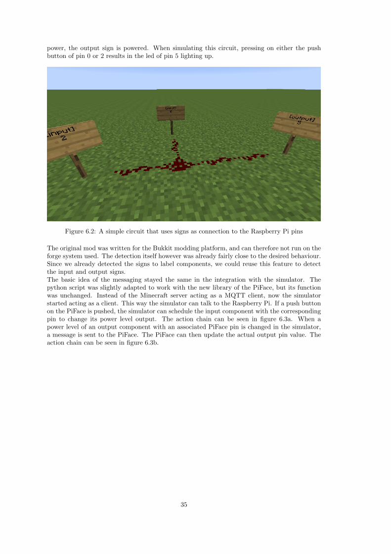
power, the output sign is powered. When simulating this circuit, pressing on either the pushbutton of pin 0 or 2 results in the led of pin 5 lighting up.
Figure 6.2: A simple circuit that uses signs as connection to the Raspberry Pi pins
The original mod was written for the Bukkit modding platform, and can therefore not run on theforge system used. The detection itself however was already fairly close to the desired behaviour.Since we already detected the signs to label components, we could reuse this feature to detectthe input and output signs.The basic idea of the messaging stayed the same in the integration with the simulator. Thepython script was slightly adapted to work with the new library of the PiFace, but its functionwas unchanged. Instead of the Minecraft server acting as a MQTT client, now the simulatorstarted acting as a client. This way the simulator can talk to the Raspberry Pi. If a push buttonon the PiFace is pushed, the simulator can schedule the input component with the correspondingpin to change its power level output. The action chain can be seen in figure 6.3a. When apower level of an output component with an associated PiFace pin is changed in the simulator,a message is sent to the PiFace. The PiFace can then update the actual output pin value. Theaction chain can be seen in figure 6.3b.
35

(a) Actions that occur when pressing the but-ton on the Raspberry Pi.
(b) Actions that occur when an output of theRaspberry Pi changes in the simulator.
Figure 6.3
36

CHAPTER 7
Open problems
7.1 Visualizing the graphs
Lets first discuss the common component of the detection and the transformation: the visu-alization. As described in chapter 3 we use the Graphviz tool set for the visualization of thegraph outputs of both algorithms. The used tool was the dot program. The dot program laysthe graph out in a hierarchical way. This layout works in really small circuits of maximum 4blocks. If any larger circuits are generated using the dot program the output becomes a mess.For example the circuit in figure 7.1 is a mess, while it doesn’t even have that much components.The user has to follow every edge to determine what the circuits is actually doing. The dottededges represent the relation the resistor nodes have to each other. If the one resistor was splitup in the transform phase, a dotted edge is created between them.
Figure 7.1: Output of the logic transformation using the dot program and the default layoutmanager.
The solution was using a different layout model. Graphviz provides a few layout models. Theone used is the neato one. The neato layout model makes use of spring forces to minimize aenergy function. The output of the same circuit is given in figure 7.2. We can now instantly seethat the circuit consists of two inputs connected to an output via an max gate. So when eitherof the inputs is on, so is the output.
One can image that this layout algorithm is quite time consuming. While testing larger circuitsof about 1000 components, the mod started choking on the call of the dot program. The dotprogram could not handle the amount of nodes, and was hogging up all the CPU power. TheGraphviz tool set does contain a layout manager that can handle large graphs, this is called sfdp.The output of the sfdp was however not readable. The decision was therefore made to implementa Minecraft command to turn off the automatic calling of the dot program. The text version
37

Figure 7.2: Output of the logic transformation using the dot program and the neato layoutmanager.
of the graph is generated even when the automatic image creation is turned off, so the user cangenerate the graph using sfdp manually if he wants to.
7.2 Detecting the circuits
The next problem worth discussing is actually programmed in on purpose. If we recall chapter2 we said that blocks can have two power levels: high and low. Some blocks can provide highpower level to a block, and some low power. Also some blocks can be powered by a high poweredblock, and some by a low powered block. One of the few components that can low power a blockis a redstone wire. If a redstone wire is on top, or wired directly into the block.
The problem is that a redstone wire always is placed on top of a block. This means thatfor every redstone wire we have to also insert a block component into the redstone circuit graph.This increases the size of the graph a lot. Also in the transformation phase, every block thatis encountered is transformed, this is of course very expensive with many blocks. However arethese blocks that are only low powered often used: no. The only way such a block is actuallyuseful is if it also connects to a block that can use this low power. Well, there is one type ofcomponent that can use this: the output component (light, piston, etc.). Since this situationdoes not occur very much this feature is not programmed into the detection algorithm. A blockthat is only powered by low power is therefore not detected. Any block that is also high poweredis however detected.
38

7.3 Transforming the circuits
The final problem lies in the splitting of resistor nodes. When connecting a component to a splitresistor node, the algorithm has to decide which of the two nodes to connect to. The algorithmdoes this by connecting to the node, that has the least incoming connections of the both. Ifboth resistor nodes have equal incoming nodes, a connection is made to the first one defined.This often goes well, however when a square of redstone wire occurs this fails. For example thedetected circuit from figure 7.3.
Figure 7.3: Detected redstone for a square of redstone wires. Attached to this square are a leverand a light.
The result of the transformation of this circuit can be seen in figure 7.4. If we follow the path wesee that the power from the input actually does reach the output. The problem occurs when theinput is turned off. The problem is the same for which we introduced the separated resistors inthe first place. Some paths create cycles in the graph. This causes the max gates to be able tointerfere with itself. This behaviour causes the signal of the output not to drop from the steadyvalue to 0, but the signal value lowers in steps.
Figure 7.4: Logic output of figure 7.3.
39

CHAPTER 8
Conclusions
In this thesis we tried to speed up the execution of Minecraft’s redstone by pulling the redstonecircuits out of the Minecraft environment. To achieve this the project was split up in four parts.The first part was defining the detection area. Since detecting the whole Minecraft world isimpossible, we created a tool to define a rectangular detection area. The next step in the projectwas the actual detection of circuits in said detection area.The algorithm used for this detection was designed by doing a couple of problem solution itera-tions. That is a algorithm was designed, but had a few problems. The next algorithm, the nextiteration, was built on top of the ideas of the previous algorithm but also keeping in mind itsproblems.While this design strategy worked out in the end, in hindsight some decisions made were not themost efficient.
The third part of the project was the transformation of redstone circuits to logic circuits. Themain goal of this transformation was transforming all the redstone components to equivalentlogic components. The transformation however had a more different sub goal. To ensure thatwire intersections could not interfere with each other, all the transformed wire nodes had to besplit up into two wires. This process works quite good most of the time, however when trans-forming a square of wire, this fails because the wrong connections are made.
The final part is the simulation of the generated logic circuits. This is achieved by imple-menting a custom simulator in C++. To transfer the circuits from the logic transformation tothe simulator a JSON based representation of the circuits is used.
Since our main goal was speeding up the redstone for educational purposes, we also wantedto interact with real life components. By extending the work of Angus Taggart we used to Rasp-berry Pi as an input/output device, that integrates into the simulator.
By testing the simulator we showed that we actually achieved the goal of speeding up the red-stone circuits. We achieved a tick rate increase of 4600%. While having this enormous tick rateincrease, the simulator also uses less memory and CPU power.
40

Bibliography
[1] Bukkit Forums. http://bukkit.org.
[2] Graphviz - Graph Visualization Software. http://www.graphviz.org.
[3] Minecraft Forge. http://www.minecraftforge.net/wiki, april 2012.
[4] Mojang AB. Statistics. https://minecraft.net/stats. (Visited 17-06-2014 17:00).
[5] Brian Benchoff. Controlling a Raspberry Pi with real life redstone. http://hackaday.com/2013/01/30/controlling-minecraft-with-a-raspberry-pi, january 2013.
[6] Jeffrey Brand and Shelley Kinash. Crafting minds in minecraft. Education TechnologySolutions, pages 55 – 58, 2013.
[7] Danny Kalev. The State of the Language: An Interview with Bjarne Stroustrup. http:
//www.devx.com/SpecialReports/Article/38813, august 2008.
[8] Wouter Koolen-Wijkstra and Ben Bruidegom. SIM-PL. http://www.science.uva.nl/
amstel/SIM-PL.
[9] Norm Matloff. Introduction to Discrete-Event Simulation and the SimPy Language. http://heather.cs.ucdavis.edu/~matloff/156/PLN/DESimIntro.pdf, february 2008.
[10] MQTT.org. Frequently Asked Questions. http://mqtt.org/faq.
[11] Pradeep Padala. NCURSES Programming HOWTO: Introduction. http://www.tldp.org/HOWTO/NCURSES-Programming-HOWTO/intro.html, 2001.
[12] Markus Persson. Terrain generation, Part 1. http://notch.tumblr.com/post/
3746989361/terrain-generation-part-1, march 2011.
[13] GNU Project. Announcing ncurses 5.9. https://www.gnu.org/software/ncurses/
ncurses.html, april 2011.
[14] Daniel Short. Teaching scientific concepts using a virtual world - minecraft. TeachingScience: The Journal of the Australian Science Teachers Association, 58(3):55 – 58, 2012.
[15] Ed. T. Bray. The JavaScript Object Notation (JSON) Data Interchange Format. http:
//tools.ietf.org/html/rfc7159, march 2014. RFC 7159.
[16] Angus Taggart. GitHub - ReallifeRedstone. https://github.com/ajtag/
ReallifeRedstone, 2013.
[17] Minecraft Wiki. Minecraft. http://minecraft.gamepedia.com/Minecraft, june 2014.
[18] Minecraft Wiki. Tutorials/Beginner’s guide. http://minecraft.gamepedia.com/
Tutorials/Beginner’s_guide, june 2014.
[19] Minecraft Wiki. World border. http://minecraft.gamepedia.com/World_border, june2014.
41

[20] Weijun Zhang. VHDL Tutorial: Learn by Example. http://hackaday.com/2013/01/30/
controlling-minecraft-with-a-raspberry-pi, june 2001.
42