minerals & energy consultants resource...
TRANSCRIPT

Resource Estimation for the Aurukun Bauxite Deposit
June 2009
Level 4, 67 St Paul’s Terrace, Spring Hill, QLD 4002, AUSTRALIA | Phone: +61 (0)7 38319154 | www.miningassociates.com.au
MINERALS & ENERGY CONSULTANTS

Aurukun Bauxite Deposit - Resource
Location
Background
Geology
Density
Modelling
Resource Estimation
Conclusions
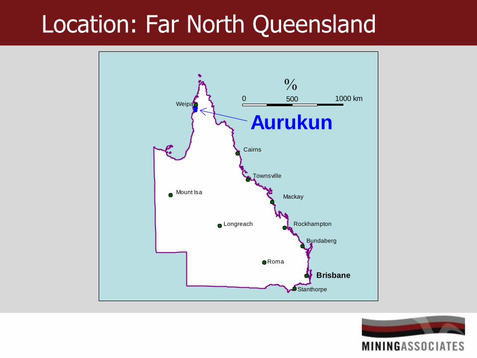
Location: Far North Queensland
0
Aurukun
500 1000 km
Cairns
Longreach
Mount Isa
Townsville
Mackay
Rockhampton
Bundaberg
Weipa
Brisbane
Stanthorpe
Roma
Introduction
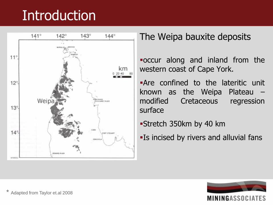
The Weipa bauxite deposits
occur along and inland from the western coast of Cape York.
Are confined to the lateritic unit known as the Weipa Plateau – modified Cretaceous regression surface
Stretch 350km by 40 km
Is incised by rivers and alluvial fans
* Adapted from Taylor et.al 2008

Introduction – Aurukun Deposit
* Adapted from EOI Aurukun Project2012
Aurukun Bauxite Deposits
South East Rim of the Weipa Bauxite Deposit
40 km south east of Weipa
History
During the 1950s and 1960s, the Aurukun bauxite resource area was explored through three different Authorities to Prospect from 1957 to 1968.
The resource was subject to an exploration program run by the State during 2004 and 2005.
During 2008, Chalco updated the resource prepared in compliance with the JORC Code, as reported in Qld QDEX system, CR-68138_1:
Total mineral resources (Measured, Indicated, Inferred) of 357Mt @51.4% Al2O3, 11.2% SiO2

Current Status
The Aurukun bauxite deposit was held by Chalco Australia Pty Ltd (Chalco) until it withdrew from the agreement with the Queensland government in 2010 and was put up for tender in 2012.
April 2013 the government of Queensland finalised a shortlist of five bidders for tender:
- Aluminium Corporation of China Limited (CHALCO),
- Australian Indigenous Resources Pty Ltd,
- Cape Alumina Consortium,
- Glencore International AG,
- Rio Tinto Aluminium Limited

Geology – Bauxite Deposits
Laterite deposits are typically laterally extensive relatively thin ore bodies, and as such present specific issues related to the lateral changes in thickness and elevation of the various horizontal layers within the deposit.
These deposits display horizontal dimensions orders of magnitude greater than the vertical dimension.
Traditionally a 2 dimensional gridded model would be utilised.
The objective was to develop a 3D block model for the Aurukun Bauxite Deposit that retained the vertical and lateral variation inherent in deposits of the type.

Regional Geology
Bauxite Development is dominantly upon the Bulimba Formation.
Age Basin Group Formation Lithology
Quaternary Quartzose gravels, sands and minor muds
Neogene Karumba Basin
Limestone, sandstone, siltstone (mainly offshore)
Paleogene Bauxite Development
Bulimba Formation
Quartzose sandstone, siltstone, coal claystone
Cretaceous Carpentaria Basin
Rolling Downs Group
Normanton Formation
Glauconitic sandstone with carbonaceous phases
Earlier formations with in the Rolling Downs Group
Coen Inlier Proterozoic metamorphics and Palaeozoic granites and volcanics
* Adapted from Taylor et.al 2008
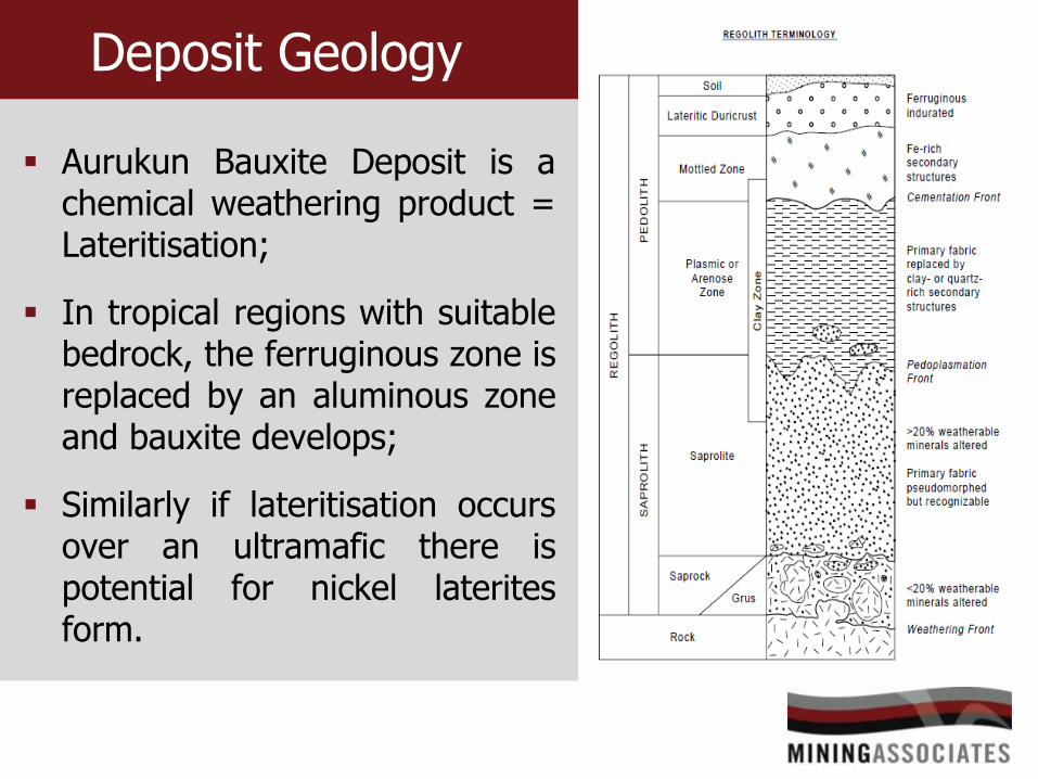
Deposit Geology
Aurukun Bauxite Deposit is a chemical weathering product = Lateritisation;
In tropical regions with suitable bedrock, the ferruginous zone is replaced by an aluminous zone and bauxite develops;
Similarly if lateritisation occurs over an ultramafic there is potential for nickel laterites form.
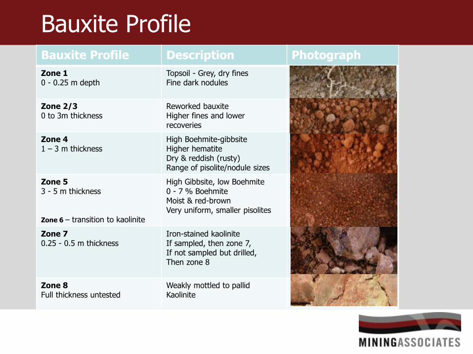
Bauxite Profile Bauxite Profile Description Photograph
Zone 1 0 - 0.25 m depth
Topsoil - Grey, dry fines Fine dark nodules
Zone 2/3 0 to 3m thickness
Reworked bauxite Higher fines and lower recoveries
Zone 4 1 – 3 m thickness
High Boehmite-gibbsite Higher hematite Dry & reddish (rusty) Range of pisolite/nodule sizes
Zone 5 3 - 5 m thickness Zone 6 – transition to kaolinite
High Gibbsite, low Boehmite 0 - 7 % Boehmite Moist & red-brown Very uniform, smaller pisolites
Zone 7 0.25 - 0.5 m thickness
Iron-stained kaolinite If sampled, then zone 7, If not sampled but drilled, Then zone 8
Zone 8 Full thickness untested
Weakly mottled to pallid Kaolinite

Bulk Density
Density values obtained from pitting were previously used.
Densities were updated with sonic drill results through the full bauxite profile over much wider
proportion of the
deposit.
Density Results from Pitting were used to validate the sonic results

Sonic Sampling “core sausage”
Retrieving the “core sausage”

Core Sausages – bagged and tagged
Individual sausages are divided into quarters, each quarter represents
¼ of a metre.

Profile Composition of bauxite with depth
Typical Mineralogical composition of bauxite profile with depth.
SG 5.3 SG 3.0
SG 2.4
SG 2.6
Zone 1 -Soil
Zone 3
1.65
Zone 4
1.63
Zone 5
1.48
Zone 6
1.55
Zone 7
1.77
Ave
rag
e Z
on
e S
G
Zone 2
1.43
SG 2.7

Modelling Approach
Hard / Soft Boundaries
HARD BOUNDARIES - prevent assay
data informing neighbouring domains,
the domains are independent.
SOFT BOUNDARIES – permit assay
data to inform neighbouring domains,
the domains are related.
Aurukun Resource Model used a combination of soft and hard boundaries, determined by the Bauxite profile.

Bauxite Profile
Soft Hard
Soft
Hard
Soft
Hard
Boundary
Type

Modelling – Folding Unfolding
The resource estimate was conducted in unfolded space.
This approach:
Preserves the laterite profile characteristics (both horizontally and vertically) irrespective of thickness or orientation;
Constrains informing samples for estimation into the zone(s) required and improves stationarity/domaining concerns; and
converts real RL to a relative position.

Block Models

Unfolded Block Model
FOLDED
LAYER C
LAYER A
LAYER B
LAYER A
LAYER C
UNFOLDED
LAYER B

Folded Block Model
Resource Estimation - Sequence
1. Bauxite layers were generally above the economic cut-off, as such, the concentration of contaminants were considered more important to model;
2. Experimental variography was undertaken using unfolded data;
3. Modelled variograms were based on total silica, and confirmed as representative of all major elements in all layers;
4. To limit order relation issues a single modelled variogram is preferred;
5. Kriging neighbourhood analysis was carried out using the modelled silica variogram;
6. Estimation was conducted in unfolded space using ordinary kriging;
7. Relative block levels were re-set of original block levels thus re-folding the block model.

Resource Classification
A number of selection criteria were used in consultation
with the project engineers and owners to meet the JORC
criteria for classification of the resource.
Zone 1 (soil) & Zone 8 (unsampled Kaolinite) were excluded;
Zone 2 to 7 were categorised in a two step process;
Vertical column selection using metallurgical and mining parameters.
Lateral resource categorisation based on estimation confidence parameters.

Resource Classification
The result is the vertical selection of intervals relating to reasonable prospects of economic extraction and classified as:
Mineable bauxite – meets reactive silica, alumina recovery;
High silica bauxite – meets alumina and recovery criteria but has high silica and is not internal waste within the mineable bauxite interval;
Thin bauxite – meets the above criteria but is too thin.

Resource Classification
Only material classified as Mineable bauxite was subject to lateral classification which incorporated a number of outputs from the kriging run.
• number of informing samples;
• drill pattern density;
• average distance of informing samples;
• kriging variance for the silica estimation run.
Based on these parameters, ”Mineable Bauxite” in high confidence areas were assigned as measured resource, low confidence areas were assigned as inferred resource and the remainder is as assigned as indicated resource.

Conclusions The resource estimation of the Aurukun lateritic deposits
presented specific issues related to the lateral changes in thickness and elevation of the various zones within the deposit where the x and y dimensions are orders of magnitude greater than the z dimension.
The solution was to do the resource estimation in “unfolded” space which maintains the zone layering irrespective of zone thickness or orientation. The block model estimation method was Ordinary Kriging done in unfolded space and then refolded.
A number of selection criteria, developed in consultation with the project engineers and owners, were applied to the deposit to define resource categories.