mini-32 - mikroelektronika · an external programmer (like mikroprog) attach it to mini-32 for...
TRANSCRIPT

ARMMINI
PIC32 development board fitted in a DIP40 form factor, containing a powerful microcontroller.
MINI-32development board for PIC32MZ

I want to express my thanks to you for being interested in our products and for having
confidence in MikroElektronika.
The primary aim of our company is to design and produce high quality electronic products
and to constantly improve the performance thereof in order to better suit your needs.
The PIC32MZ, ARM® and Windows® logos and product names are trademarks of Texas Instruments®, ARM® Holdings and Microsoft® in the U.S.A. and other countries.
TO OUR VALUED CUSTOMERS
Nebojsa Matic
General Manager

Page 3
Introduction to MINI-32 for PIC32MZ 4
Key features 4
System specifications 5
1. Programming with mikroBootloader 6
step 1 – Connecting MINI-32 for PIC32MZ 6
step 2 – Browsing for .HEX file 7
step 3 – Selecting .HEX file 7
step 4 – Uploading .HEX file 8
step 5 – Finish upload 9
2. Schematic 10
3. Pinout 11
4. Dimensions 12
Table of Contents

Page 4
Introduction to MINI-32 for PIC32MZ
Key features
01
02
03
04
05
06
07
Connection pads
Micro USB connector
DATA LED
STAT LED
POWER supply LED
Reset button
Power supply regulator
PIC32MZ1024EFH064 microcontroller08
Miniature and powerful development tool designed to work as a
standalone device or as a MCU card in DIP40 socket. MINI-32 for
PIC32MZ is preprogrammed with USB HID bootloader so it is not
necessary to have an external programmer. If you need to use
an external programmer (like mikroProg) attach it to MINI-32 for
PIC32MZ via pads marked with TMS,
TDO, TCK, TDI.

Page 5
System specifications
power supply
3.3V via pads or 5V via USB
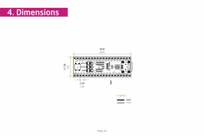
board dimensions
50.8 x 17.78mm (2 x 0.7“)
weight
~6g (0.013 lbs)
power consumption
depends on MCU state (max current
into 3.3V pad is 300mA)
Connection pads
Micro USB connector
DATA LED
STAT LED
POWER supply LED
Reset button
Power supply regulator
PIC32MZ1024EFH064 microcontroller
0102
03 04 05
06
08
07

Page 6
1. Programming with mikroBootloader
You can program the microcontroller with the bootloader that
is preprogrammed into the device by default. To transfer .hex
file from a PC to the MCU you need the bootloader software
(mikroBootloader USB HID) which can be downloaded from:
After the software is downloaded unzip it to the desired loca-
tion and start mikroBootloader USB HID software.
Figure 1-1: USB HID mikroBootloader window
step 1 – Connecting MINI-32
01
01
To start, connect the USB cable, or if already connected press the Reset button on your MINI-32 board. Click the Connect button within 5s to enter the bootloader mode, otherwise existing microcontroller program will execute.
download.mikroe.com/examples/starter-boards/mini/pic32mz/mini-pic32mz-mikrobootloader-usb-hid-v280.zip

Page 7
step 3 – Selecting .HEX file step 2 – Browsing for .HEX file
Figure 1-2: Browse for HEX Figure 1-3: Selecting HEX
02
01
Click the ”Browse for HEX” button and from a pop-up window (Figure 1-3) choose the .HEX file which will be uploaded to MCU memory.
Select .HEX file using open dialog window.
Click Open.
01
01
01

Page 8
step 4 – Uploading .HEX file
Figure 1-4: Begin uploading Figure 1-5: Progress bar
01
01
01 01To start .HEX file bootloading click the Begin uploading button.
You can monitor .HEX file uploading via progress bar

Page 9
step 5 – Finish upload
Figure 1-6: Restarting MCU Figure 1-7: mikroBootloader ready for next job
01
01
Click OK after uploading is finished and wait for 5 seconds. Board will automatically reset and your new program will execute.

Page 10
2. Schematic
HD1 HD2
SPI1-SS
I2C-SCLCAN-Rx
INT0
PWM0
CAN-TxI2C-SDA
INT1
INT2
INT3
SPI1-MISOSPI1-MOSI
SPI1-SCKPWM1
PWM2PWM3
UART0-TxUART0-Rx
AN0AN1AN2AN3AN4
AN5AN6
UART1-TxUART1-Rx
SPI0-SS
SPI0-MISOSPI0-MOSISPI0-SCK
TCK/SWCTMS/SWD
TDITDOTDO
1234567891011121314151617181920 21
22232425262728293031323334353637383940nMCLR
VDDVSS
VDDVSS
VCC-USB
T1
#MCLR
D_ND_PUSBD_P
USBD_N
VCC-USB
C12
10µF
C13
10µF
C8
0.10µF
C9
0.10µF
C10
0.10µF
C11
0.10µF
C6
0.10µF
C5
0.10µF
GND
GND
AVDD
FB1
VDD
VDD
C7
0.10µF
R1410k
R15
1k
RD2
RB2RB3
RB5
RB10RB11
RB12RB13
RB15
USBD_PUSBD_N
STANDBY 1
GND 2OUT3
VCC4
Y2
24MHz
GND
CLK_IN
C40.10µF
R11 1k
VBUS
VBUS
VDD VDD
VDD
VDD
STAND-BY1
GND2 OUT 3
VCC 4Y1 32.768kHz
VDD
C1
0.10µF
LD1 LD2 LD3
R17470
R18470
R19470
31 2VO
UT
GN
D
VIN
U2
NCP1117ST33
C2
10µF
C3
10µF
R1327 R1627
FB2 FERRITE
TVS1 TVS2
R121M
12345 ID
D+D-VBUS
GND
CN1
ZX62-AB-5PA(11)
RE51
RE62
RE73
RG64
RG75
RG86
VSS7
VDD8
MCLR9
RG910
RB511
RB412
RB313
RB214
RB115
RB016
RB6
17
RB7
18
AVD
D19
AVSS
20
RB8
21
RB9
22
RB10
23
RB11
24
VSS
25
VDD
26
RB12
27
RB13
28
RB14
29
RB15
30
RC12
31
RC15
32
VBUS 33VUSB3V3 34VSS 35D- 36D+ 37RF3 38VDD 39VSS 40RF4 41RF5 42RD9 43RD10 44RD11 45RD0 46RC13 47RC14 48
RD1
49RD
250
RD3
51RD
452
RD5
53VD
D54
VSS
55RF
056
RF1
57RE
058
VSS
59VD
D60
RE1
61RE
262
RE3
63RE
464
GND65 U1
PIC32MZ1024EFH064-I/MR
RB14
RB8
RB7
RB9
RB0RB1
RG9#MCLR
RG8RG7RG6
RE5
RE3
RF1RF0
RD3
RD5
RD4
RD10RD11
RD9
RD0
RF3
RB15RB14
RB8RB7
RB9
RB2RB0
#MCLR
RB1
RB3RB5
RG9
RG8RG7
RG6RE5RE3
RF1RF0
RD5RD4
RD3RD2
RB11
RB10RB12
RB13
RD0RF3
RD11
RD10RD9
RE7
RB6
RE7
RB6
RF5RF4
RF5RF4
SCLK_IN
VDD
VDD
RE1
RE0
RE0RE1

Page 11
3. Pinout
RE3
RE5
SPI1-SCK RG6
PWM1 RG8
PWM0 RG7
INT3 RG9
RB3
CAN-Tx RB5
GND VSS
3.3V Power supply VDD
INT2 RB1
RE7
RB0
SPI1-SS RB2
AN4 RB7
AN3 RB8
AN2 RB9
AN1 RB14
AN0 RB15
#MCLRPin functionsPin functions
CAN
Analog I/O
RF0
RF1
RD3
RD2
RD5
RD4
RF4
RF5
RB11
RB13
VSS
VDD
RD0
RF3
RB10
RB12
RD9
RD10
RB6
RD11
SPI1-MISO
SPI1-MOSI
UART0-Rx
GND
3.3V Power supply
INT1
INT0
TMS/SWD
SPI0-MOSI
SPI0-MISO
I2C
UART0
TCK/SWC
SPI0-SS
SPI0-SCKSPI0
AN5
AN6
SPI LinesInterrupt LinesAnalog Lines I2C Lines UART lines CAN lines PWM lines
PWM2
PWM3
TDI
TDO
I2C-SCL
I2C-SDA
UART1
UART0-Tx
UART0-Rx
UART0-Tx
nMCLR
CAN-Rx
Page 12 Page 13
4. Dimensions
50.82000
2.54100
17.7
870
0
Legend
mmmils
32PIC32M
Z
50.82000
2.54100
17.7
870
0
Legend
mmmils
32PIC32M
Z

Page 13
Notes:

Page 14
Notes:

Page 15
DISCLAIMER
All the products owned by MikroElektronika are protected by copyright law and international copyright treaty. Therefore, this manual is to be treated as any other copyright material. No part of this manual, including product and software described herein, may be reproduced, stored in a retrieval system, translated or transmitted in any form or by any means, without the prior written permission of MikroElektronika. The manual PDF edition can be printed for private or local use, but not for distribution. Any modification of this manual is prohibited.
MikroElektronika provides this manual ‘as is’ without warranty of any kind, either expressed or implied, including, but not limited to, the implied warranties or conditions of merchantability or fitness for a particular purpose.
MikroElektronika shall assume no responsibility or liability for any errors, omissions and inaccuracies that may appear in this manual. In no event shall MikroElektronika, its directors, officers, employees or distributors be liable for any indirect, specific, incidental or consequential damages (including damages for loss of business profits and business information, business interruption or any other pecuniary loss) arising out of the use of this manual or product, even if MikroElektronika has been advised of the possibility of such damages. MikroElektronika reserves the right to change information contained in this manual at any time without prior notice, if necessary.
TRADEMARKS
The MikroElektronika name and logo, the MikroElektronika logo, mikroC™, mikroBasic™, mikroPascal™, MINI™, EasyMX PRO™, mikroBUS™, click™ boards, mikroProg™, and mikromedia™ are trademarks of MikroElektronika. All other trademarks mentioned herein are property of their respective companies.All other product and corporate names appearing in this manual may or may not be registered trademarks or copyrights of their respective companies, and are only used for identification or explanation and to the owners’ benefit, with no intent to infringe.
Copyright © 2014 MikroElektronika. All Rights Reserved.
HIGH RISK ACTIVITIES
The products of MikroElektronika are not fault – tolerant nor designed, manufactured or intended for use or resale as on – line control equipment in hazardous environments requiring fail – safe performance, such as in the operation of nuclear facilities, aircraft navigation or communication systems, air traffic control, direct life support machines or weapons systems in which the failure of Software could lead directly to death, personal injury or severe physical or environmental damage (‘High Risk Activities’). MikroElektronika and its suppliers specifically disclaim any expressed or implied war-ranty of fitness for High Risk Activities.

If you want to learn more about our products, please visit our website at www.mikroe.com
If you are experiencing some problems with any of our products or just need additional
information, please place your ticket at helpdesk.mikroe.com
If you have any questions, comments or business proposals,
do not hesitate to contact us at [email protected]
ARMMINI