mini body control module - wtxmc.orgwtxmc.org/minicooperdocs/body control.pdf · 2002-07 geninfo...
TRANSCRIPT

2002-07 GENINFO
Body Control - Overview - MINI
MINI BODY CONTROL MODULE
BODY CONTROL MODULE (BC1)
The BC1, similar in operation to the BMW General Module, controls several systems on the MINI. It is connected to the K-Bus to allow sub-systems to communicate with other systems and to enable diagnostic communication with the sub-systems.
The BC1 is located at the base of the A Pillar on the right hand side of the vehicle. It utilizes four (4) connections: one 20-pin connection and three (3) 54-pin connections.
Fig. 1: BC1 Connectors Courtesy of BMW OF NORTH AMERICA, INC.
2006 MINI Cooper S
2002-07 GENINFO Body Control - Overview - MINI
2006 MINI Cooper S
2002-07 GENINFO Body Control - Overview - MINI
Microsoft
Tuesday, February 16, 2010 10:04:25 AM Page 1 © 2005 Mitchell Repair Information Company, LLC.
Microsoft
Tuesday, February 16, 2010 10:04:29 AM Page 1 © 2005 Mitchell Repair Information Company, LLC.

Fig. 2: BC1 Mounting Location Courtesy of BMW OF NORTH AMERICA, INC.
Systems Controlled by the BC1 are:
Electrical Load Management
Vehicle Information System
Central Locking/Remote Locking
Power Windows
Anti-Theft System (DWA)
Exterior/Interior Lighting
Front and Rear Wipe/Wash
Heated Rear Window/Heated Front Windshield
Fresh/Re-Circulation Air Control
Air Conditioning
BC1 Notes
When diagnosing electrical problems, Don't Forget, the BC1 has more than one source of KL15 or KL30.
Always check ALL the fuse that supply power to the BC1.
2006 MINI Cooper S
2002-07 GENINFO Body Control - Overview - MINI
Microsoft
Tuesday, February 16, 2010 10:04:25 AM Page 2 © 2005 Mitchell Repair Information Company, LLC.

Fig. 3: BC1 Incorporates Components
2006 MINI Cooper S
2002-07 GENINFO Body Control - Overview - MINI
Microsoft
Tuesday, February 16, 2010 10:04:25 AM Page 3 © 2005 Mitchell Repair Information Company, LLC.

Courtesy of BMW OF NORTH AMERICA, INC.
ELECTRICAL LOAD MANAGEMENT
Purpose of the System
The purpose of the Electrical Load Management System is to reduce battery drain while vehicles are transported, stored or not used for long periods of time. Two modes of operation are possible:
Transit Mode
Normal Mode
Transit Mode(Transportation Mode)
Transit Mode is used to prevent excessive battery drain during movement of the vehicle from the manufacturing point to the dealer. After vehicle manufacture, the BC1 is programmed with correct market and equipment information and placed in transit mode. Transit mode allows some limited electrical functionality. This mode should be deleted during the vehicle's pre-delivery inspection.
TRANSIT MODE LIMITED FUNCTIONS
Normal Mode
In Normal Mode the electrical management system provides three different methods of protection for the vehicle electrical system.
Low Voltage
Sleep Mode
Power Down During Cranking
Low Voltage
In the event of the battery voltage falling below 11.8 volts the BC1 will deactivate and inhibit the operation of the heated rear window and optional heated front screen until the voltage level exceeds 12.2 volts.
Sleep Mode
To reduce closed circuit current draw the BC1 enters its sleep mode 16 minutes after switching off terminal R or within two minutes of externally locking the car.
Function LimitsInterior/Map Lights Auto shut off after 1 minute instead of 16Heated Rear Window Limited to 1 minute operating timeHeated Windshield Limited to 1 minute operating timeAC Blower Limited to 1 minute operating timeExterior Lights Operate only in ignition position 1,2, or 3DWA Siren Always Disarmed
2006 MINI Cooper S
2002-07 GENINFO Body Control - Overview - MINI
Microsoft
Tuesday, February 16, 2010 10:04:25 AM Page 4 © 2005 Mitchell Repair Information Company, LLC.

The BC1 will wake up if the ignition is switched from position 0 to position 1 or the BC1 senses a change at one of its monitored inputs.
The K-Bus will enter a pre-sleep mode if no bus messages are received within 50 seconds and sleep mode if no messages are received in 60 seconds. The BC1 or any module on the K-Bus can initiate a wake-up call.
Power Down During Cranking
During starting of the engine certain loads are deactivated to allow maximum voltage to be applied to the starter motor. These loads are then re-introduced over a 2-second period after the engine has started in order to limit the current draw from the battery and load on the generator.
POWER DOWN DURING CRANKING
VEHICLE INFORMATION STORAGE
The BC1 stores the total mileage and service interval data (SIA) in memory as back up for the IKE.
The Vehicle Identification Number (VIN) is entered during coding of the BC1 and can only be over-written if the total mileage is less than 100 km. The VIN stored in the IKE and BC1 are checked each time the ignition is switched on.
The mileage and SIA data is also updated in the BC1 every 100 km (62 miles) of continuous driving.
The BC1 will not accept mileage from the IKE if the value stored is over 1000 km less than that stored in the IKE. If this occurs the BC1 must be replaced.
If both the BC1 and the IKE have to be replaced, replace one module, and only after coding it, replace the other module.
Order Load Delay after startup1 Wipers and headlights 0.0 sec2 Blower motor 0.5 sec3 Power windows 1.0 sec4 Heated rear window 1.5 sec5 Heated front screen 2.0 sec
NOTE: The power down is limited to a maximum of 45 seconds, after which time all loads are enabled. This ensures that functions are not inhibited in the event of an ignition switch malfunction or incorrect cranking signal received by the BC1.
NOTE: Never replace both the IKE and the BC1 at the same time. If this were to occur, the mileage stored and displayed will reset to 0 miles. If the mileage of the vehicle is not known, a vehicle disclosure statement sticker has to be placed on the B-Pillar with the mileage set to TMU (Total Mileage Unknown).
2006 MINI Cooper S
2002-07 GENINFO Body Control - Overview - MINI
Microsoft
Tuesday, February 16, 2010 10:04:25 AM Page 5 © 2005 Mitchell Repair Information Company, LLC.

CENTRAL LOCKING SYSTEM
Standard on the MINI is a fully integrated Locking System. The central locking system incorporates components from different systems all tied together in the BC1.
2006 MINI Cooper S
2002-07 GENINFO Body Control - Overview - MINI
Microsoft
Tuesday, February 16, 2010 10:04:25 AM Page 6 © 2005 Mitchell Repair Information Company, LLC.

Fig. 4: Central Locking System Incorporates Components Courtesy of BMW OF NORTH AMERICA, INC.
2006 MINI Cooper S
2002-07 GENINFO Body Control - Overview - MINI
Microsoft
Tuesday, February 16, 2010 10:04:25 AM Page 7 © 2005 Mitchell Repair Information Company, LLC.

Purpose of the System
The Central Locking System is controlled by the BC1 via internal relays and is activated by using the key in the drivers door, remote key operation or from inside using the central locking switch. The Central Locking System performs the following functions:
Lock/Unlock Vehicle Doors
Release Tailgate
Lock/Unlock Fuel Filler Door
Convenience Opening and Closing of windows and sunroof
Components of the System
BC1
The internal relays are activated based on inputs received by the BC1. The relays are activated on a time basis dependent upon battery voltage.
Polarity to the locking motors is reversed at the BC1 to drive them in both directions.
BC1 CENTRAL LOCKING RELAY ACTIVATION TIME
Fig. 5: Door Latch With Integral Locking Motors Courtesy of BMW OF NORTH AMERICA, INC.
Battery voltage (V) <9 <10 <11 <12 <13 <14 <15 <15Relay on Time (sec) 1.0 0.85 0.7 0.6 0.5 0.45 0.4 0.4
NOTE: Internal door lock relays are always driven for the maximum time based on battery voltage, except in the event of a sticking relay. If a sticking Relay is
2006 MINI Cooper S
2002-07 GENINFO Body Control - Overview - MINI
Microsoft
Tuesday, February 16, 2010 10:04:25 AM Page 8 © 2005 Mitchell Repair Information Company, LLC.
Door Latches
The door latches have two integral motors, which can be used to put the latch into three different mechanical states:
Unlocked - doors can be opened from the inside or outside release handles.
Central (Single) Lock - doors can only be opened from the inside release handle.
Central Arrest (Double Lock)- doors cannot be opened from any door handle.
Micro-switches for the door contacts are integrated in the door latches. On the driver's door latch assembly, the key lock/unlock micro-switches are also included.
The central locking motors can be driven directly from any mechanical state to any other mechanical state; there is no need to go via any intermediate states.
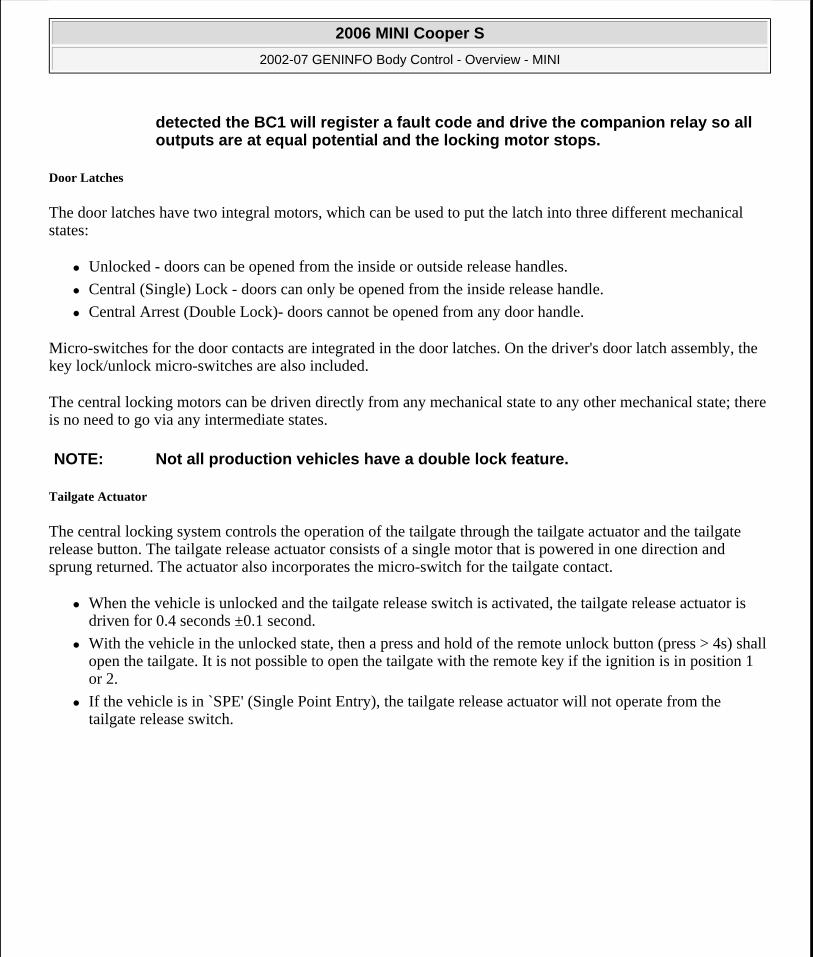
Tailgate Actuator
The central locking system controls the operation of the tailgate through the tailgate actuator and the tailgate release button. The tailgate release actuator consists of a single motor that is powered in one direction and sprung returned. The actuator also incorporates the micro-switch for the tailgate contact.
When the vehicle is unlocked and the tailgate release switch is activated, the tailgate release actuator is driven for 0.4 seconds ±0.1 second.
With the vehicle in the unlocked state, then a press and hold of the remote unlock button (press > 4s) shall open the tailgate. It is not possible to open the tailgate with the remote key if the ignition is in position 1 or 2.
If the vehicle is in `SPE' (Single Point Entry), the tailgate release actuator will not operate from the tailgate release switch.
detected the BC1 will register a fault code and drive the companion relay so all outputs are at equal potential and the locking motor stops.
NOTE: Not all production vehicles have a double lock feature.
2006 MINI Cooper S
2002-07 GENINFO Body Control - Overview - MINI
Microsoft
Tuesday, February 16, 2010 10:04:25 AM Page 9 © 2005 Mitchell Repair Information Company, LLC.

Fig. 6: Tailgate Release Actuator Courtesy of BMW OF NORTH AMERICA, INC.
Fuel Filler Lock
The fuel filler actuator is activated directly by the BC1. It is located on the driver's side of the vehicle and can be easily removed if the rear left tail lamp is removed first.
Fig. 7: Fuel Filler Lock Courtesy of BMW OF NORTH AMERICA, INC.
2006 MINI Cooper S
2002-07 GENINFO Body Control - Overview - MINI
Microsoft
Tuesday, February 16, 2010 10:04:25 AM Page 10 © 2005 Mitchell Repair Information Company, LLC.
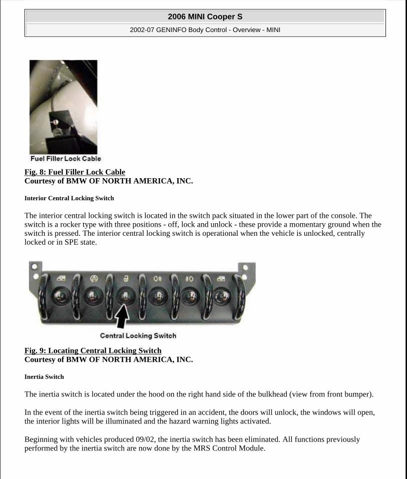
Fig. 8: Fuel Filler Lock Cable Courtesy of BMW OF NORTH AMERICA, INC.
Interior Central Locking Switch
The interior central locking switch is located in the switch pack situated in the lower part of the console. The switch is a rocker type with three positions - off, lock and unlock - these provide a momentary ground when the switch is pressed. The interior central locking switch is operational when the vehicle is unlocked, centrally locked or in SPE state.
Fig. 9: Locating Central Locking Switch Courtesy of BMW OF NORTH AMERICA, INC.
Inertia Switch
The inertia switch is located under the hood on the right hand side of the bulkhead (view from front bumper).
In the event of the inertia switch being triggered in an accident, the doors will unlock, the windows will open, the interior lights will be illuminated and the hazard warning lights activated.
Beginning with vehicles produced 09/02, the inertia switch has been eliminated. All functions previously performed by the inertia switch are now done by the MRS Control Module.
2006 MINI Cooper S
2002-07 GENINFO Body Control - Overview - MINI
Microsoft
Tuesday, February 16, 2010 10:04:25 AM Page 11 © 2005 Mitchell Repair Information Company, LLC.

Fig. 10: Inertia Switch Courtesy of BMW OF NORTH AMERICA, INC.
Principle of Operation
Lock/Unlock
The vehicle can be locked/unlocked from:
The lock/unlock button on the radio remote key
The driver's door cylinder
The interior central lock switch (unlock only when centrally locked from inside)
The vehicle will also be unlocked if the inertia switch is tripped from ignition position 1. If a valid key is recognized in the ignition (EWS) when the vehicle is central arrested the locks move to the unlocked state.
Central Lock (Single Lock)
The car can be centrally locked from inside by using the interior central locking switch located in the switch center, provided the driver's door is closed.
Central Arrest (Double Lock)
To put the locks in the arrest position the remote control lock button or the driver's door lock is used. It is not possible to unlock the car from the interior central locking switch when in the central arrest condition. If the passenger door is left open, an attempt to central arrest will result in the car being put into the centrally locked condition.
Starting with 9/2002 production vehicles, the double lock feature for the doors has been eliminated. The feature will be phased back into production.
Automatic Lock/Unlock
If automatic lock is configured in Vehicle Memory (coding), when the vehicle speed exceeds 4 km/h the vehicle
2006 MINI Cooper S
2002-07 GENINFO Body Control - Overview - MINI
Microsoft
Tuesday, February 16, 2010 10:04:25 AM Page 12 © 2005 Mitchell Repair Information Company, LLC.

will centrally lock. The car automatically unlocks when the ignition is switched to position 0 and the handbrake is applied on manual transmission cars or the selector lever is in PARK on automatic models.
Lock When Running
The lock when running feature allows the car to be externally locked from the drivers door using a second key while the engine is running - provided the gear selector lever is in PARK on automatic transmission vehicles, or the handbrake applied on manual transmission vehicles.
Selective Unlocking (Single Point Entry - SPE)
This function enables just the driver's door to be unlocked from the first unlock action of the remote key or door lock, the passenger door lock moves from central arrest to the centrally locked state. To unlock the complete vehicle repeat the unlock action a second time.
Door Latches
The door latch mechanisms (driver and passenger) contain micro-switches for door position information. The micro-switches are open (Signal-High) when the doors are closed and are closed (Signal pulled low to ground) when the doors are open.
The Drivers door Lock/Unlock switch provides a Low signal to indicate position request.
Door Lock Motors (one Lock and one Double lock) have polarity reversed by the BC1 to operate in either direction. The motors and latch mechanism provide no feedback to the BC1 as to position and are driven with each lock or unlock request irrespective of their current position.
To avoid overloading the motors are blocked out after 10 operations in 1 minute. The motors will be placed in the unlock state for approximately 1 minute.
Tailgate Release Actuator (Coupe)
The tailgate release actuator has only two positions Trunk closed or trunk open. Upon receiving a tailgate open request, either from the tailgate release button, or the remote key the BC1 activates the motor. The motor is powered in one direction and sprung in the other direction.
On early production vehicles, there was no manual unlock cable or lever for the tailgate release mechanism. The only method for opening of the tailgate was through the electrical activation of the release motor.
Later production vehicles have a cable that is routed from the actuator to under the rear seat bench. This allows the rear tailgate to be opened in case of an electrical failure.
Rear Hatch Concept (Convertible)
The rear hatch for the R52 MINI Convertible is a different from the coupe. The actuator motor for unlocking the rear hatch locks is driven by pressing the button between the license plate lights.
The actuator motor moves a lever, which in turn moves the attached cable assemblies of the rear hatch locks. As
2006 MINI Cooper S
2002-07 GENINFO Body Control - Overview - MINI
Microsoft
Tuesday, February 16, 2010 10:04:25 AM Page 13 © 2005 Mitchell Repair Information Company, LLC.

the lever moves the cable assemblies are pulled thus releasing the rear hatch locks.
The rear hatch can opens downward. Two steel cables with a sprung retractor systems hold the opened rear hatch in position. This makes it possible to use the rear hatch with the exterior-mounted hinges can be used as a loading facility that can support loads weighing up to 80 kg (176 lbs).
The steel cables are wound up by the spring effect in the retractor housing when the rear hatch is closed.
Fig. 11: Rear Hatch Concept (Convertible) Components Courtesy of BMW OF NORTH AMERICA, INC.
Emergency Opening of Rear Hatch
When there is no power, e.g. battery discharged, the rear hatch can be opened by pulling the emergency release handle. After folding down the rear seat backrest, the emergency release handle is accessible through the luggage compartment.
Fuel Filler Actuator
Driven by the BC1 the Fuel Filler Actuator is only placed in the lock position when the vehicle is put in Central Arrest (Double Lock). The fuel filler actuator has only one motor since it does not have a central lock position (Single Lock).
In the case of failure of this actuator, there is a mechanical release attached to the bow-den cable that comes from the actuator. To access this release remove the trunk area's left trim panel.
Inertia Switch
WARNING: Risk of injury when opening the housing!
2006 MINI Cooper S
2002-07 GENINFO Body Control - Overview - MINI
Microsoft
Tuesday, February 16, 2010 10:04:25 AM Page 14 © 2005 Mitchell Repair Information Company, LLC.

In the event of an impact registering at greater than 14G the Inertia Switch goes open. This open removes the voltage from X254 pin 21 at the BC1 (J3 54-pin Natural connector). The trigger of the inertia switch causes the BC1 to unlock doors.
The inertia switch has been eliminated from vehicles produced 9/2002 and later. The function is now carried out by the MRS control unit.
Fig. 12: Central Lock Circuit Diagram Courtesy of BMW OF NORTH AMERICA, INC.
Interior Central Lock Switch
The Interior Central Lock Switch is a three position spring loaded switch. When pressure applied to the switch in either direction is released the switch will return to a middle neutral position.
The switch supplies two high/low signals to the BC1, one for lock and one for unlock. When the switch is put in the lock or unlock position the signal for that request is pulled low at the BC1. Terminals 42 and 44 at the BC1 connector X255 (J2 54-pin Blue) are responsible for the inputs.
Remote Central Locking (FZV)
NOTE: On vehicles without the inertia switch (9/2002 production on), the only way to activate a crash signal is for the MRS 4 control unit to detect an impact.
2006 MINI Cooper S
2002-07 GENINFO Body Control - Overview - MINI
Microsoft
Tuesday, February 16, 2010 10:04:25 AM Page 15 © 2005 Mitchell Repair Information Company, LLC.
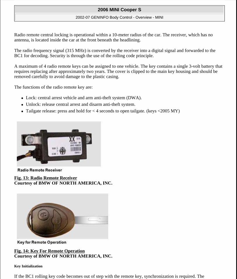
Radio remote central locking is operational within a 10-meter radius of the car. The receiver, which has no antenna, is located inside the car at the front beneath the headlining.
The radio frequency signal (315 MHz) is converted by the receiver into a digital signal and forwarded to the BC1 for decoding. Security is through the use of the rolling code principle.
A maximum of 4 radio remote keys can be assigned to one vehicle. The key contains a single 3-volt battery that requires replacing after approximately two years. The cover is clipped to the main key housing and should be removed carefully to avoid damage to the plastic casing.
The functions of the radio remote key are:
Lock: central arrest vehicle and arm anti-theft system (DWA).
Unlock: release central arrest and disarm anti-theft system.
Tailgate release: press and hold for < 4 seconds to open tailgate. (keys <2005 MY)
Fig. 13: Radio Remote Receiver Courtesy of BMW OF NORTH AMERICA, INC.
Fig. 14: Key For Remote Operation Courtesy of BMW OF NORTH AMERICA, INC.
Key Initialization
If the BC1 rolling key code becomes out of step with the remote key, synchronization is required. The
2006 MINI Cooper S
2002-07 GENINFO Body Control - Overview - MINI
Microsoft
Tuesday, February 16, 2010 10:04:25 AM Page 16 © 2005 Mitchell Repair Information Company, LLC.

synchronization procedure can be carried out in two ways:
Press either the remote key lock or unlock button four times in succession.
With the car unlocked, switch on the ignition briefly and then off and remove the key, now within 10-seconds press the lock and unlock buttons in succession.
It is not necessary to synchronize all the keys together. As the key codes are stored in the BC1, the synchronization procedure is simply aligning the rolling code in the BC1 to the individual key and will not affect any additional keys.
On new style keys, initialization can be performed as follows:
Turn ignition to KLR and remove key.
Press and hold the unlock button.
While holding the unlock button down, press and release the lock button three times.
Fig. 15: Key Courtesy of BMW OF NORTH AMERICA, INC.
As confirmation, the vehicle will lock and unlock. To initialize a additional keys (up to three) follow step two and three for each key.
Replacement Keys
Each key has its own individual bar code that is supplied with the key. This bar code is used to enter manually the data into the DISplus for programming it to the BC1.
If the BC1 requires replacing the bar code must be read out with the DISplus and programmed into the new BC1 after replacement.
POWER WINDOWS
Standard on the MINI is power operation of the Driver and Passenger windows. The Rear Quarter windows are fixed.
2006 MINI Cooper S
2002-07 GENINFO Body Control - Overview - MINI
Microsoft
Tuesday, February 16, 2010 10:04:25 AM Page 17 © 2005 Mitchell Repair Information Company, LLC.

Fig. 16: Power Operation Diagram Of Driver And Passenger Windows Courtesy of BMW OF NORTH AMERICA, INC.
2006 MINI Cooper S
2002-07 GENINFO Body Control - Overview - MINI
Microsoft
Tuesday, February 16, 2010 10:04:25 AM Page 18 © 2005 Mitchell Repair Information Company, LLC.
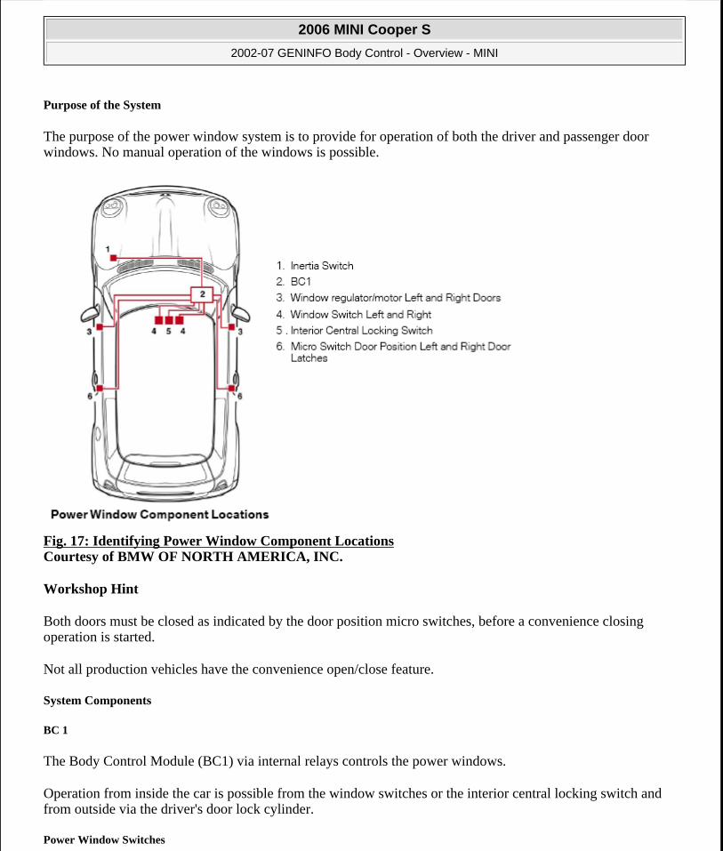
Purpose of the System
The purpose of the power window system is to provide for operation of both the driver and passenger door windows. No manual operation of the windows is possible.
Fig. 17: Identifying Power Window Component Locations Courtesy of BMW OF NORTH AMERICA, INC.
Workshop Hint
Both doors must be closed as indicated by the door position micro switches, before a convenience closing operation is started.
Not all production vehicles have the convenience open/close feature.
System Components
BC 1
The Body Control Module (BC1) via internal relays controls the power windows.
Operation from inside the car is possible from the window switches or the interior central locking switch and from outside via the driver's door lock cylinder.
Power Window Switches
2006 MINI Cooper S
2002-07 GENINFO Body Control - Overview - MINI
Microsoft
Tuesday, February 16, 2010 10:04:25 AM Page 19 © 2005 Mitchell Repair Information Company, LLC.
The window switches are located in the switch pack situated in the lower part of the center console. A single connection is used to connect the switch pack to the vehicle harness.
In the event of the BC1 receiving window up and down signals simultaneously, the following will apply:
If the window is moving it will stop immediately.
If the window is not moving it will not move under any switch operation until the fault is reset.
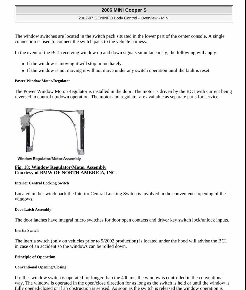
Power Window Motor/Regulator
The Power Window Motor/Regulator is installed in the door. The motor is driven by the BC1 with current being reversed to control up/down operation. The motor and regulator are available as separate parts for service.
Fig. 18: Window Regulator/Motor Assembly Courtesy of BMW OF NORTH AMERICA, INC.
Interior Central Locking Switch
Located in the switch pack the Interior Central Locking Switch is involved in the convenience opening of the windows.
Door Latch Assembly
The door latches have integral micro switches for door open contacts and driver key switch lock/unlock inputs.
Inertia Switch
The inertia switch (only on vehicles prior to 9/2002 production) is located under the hood will advise the BC1 in case of an accident so the windows can be rolled down.
Principle of Operation
Conventional Opening/Closing
If either window switch is operated for longer than the 400 ms, the window is controlled in the conventional way. The window is operated in the open/close direction for as long as the switch is held or until the window is fully opened/closed or if an obstruction is sensed. As soon as the switch is released the window operation is
2006 MINI Cooper S
2002-07 GENINFO Body Control - Overview - MINI
Microsoft
Tuesday, February 16, 2010 10:04:25 AM Page 20 © 2005 Mitchell Repair Information Company, LLC.
terminated.
One-Touch Opening
If either window switch is operated for less than 400 ms, the system shall assume one-touch mode. In one-touch mode the window travels to the fully open position. The window can be stopped at any time by briefly pressing the relevant window switch in either direction. The motor is powered for 15 seconds and then switched off.
One-Touch Closing
Because the windows do not utilize an anti-trap feature, one-touch closing operation is not functional in the US market.
If the driver's side window switch is operated for less than 400 ms, the system shall assume one-touch mode. In one-touch mode the window travels to the fully closed position. The window can be stopped at any time by briefly pressing the window switch in either direction. The motor is powered for 15 seconds and then switched off.
Short Drop/Raise Function
On opening the driver's or passenger's door the window is partially lowered to the clear of seal position (COS), on closing the relevant door the window will close fully up into the seal. This function aids opening and closing of the doors.
The BC1 activates the window for 150 ms to open slightly. For the close procedure the window is powered for a maximum of 600 ms or until the cut-out current is seen by the BC1.
Convenience Opening/Closing
The windows can be conveniently opened and closed from outside the car at the driver's door lock. The key must be held over in the desired position to lock the car and close the windows or unlock the car and open the windows. Operation is ceased when the key is released.
The windows can also be conveniently opened from inside the car by holding the interior central locking switch in the unlock position. Operation is ceased when the switch is released.
BC1
Based on input received the BC1 energizes the appropriate internal relay to power the window up/down. The BC1 monitors the current draw of the motor at 2 ms intervals for the first 50 ms and then at 100 ms intervals.
The peak current measured is reduced by 4A and this value is then used as the cut-out current at which the BC1 will deactivate the motor. During operation of the window motor, if no cut-out current is seen the BC1 will switch off the motor after 15 seconds.
If at any point the current exceeds 35A the BC1 will deactivate the motor immediately.
Power Window Current Monitoring
2006 MINI Cooper S
2002-07 GENINFO Body Control - Overview - MINI
Microsoft
Tuesday, February 16, 2010 10:04:25 AM Page 21 © 2005 Mitchell Repair Information Company, LLC.

Peak Current = Current value at start-up of motor
Stall Current = Current value at which the motor stops
Cut-Out Current = Peak current minus 4Amps
Workshop Hint
If a relay is stuck on, a fault is detected and the BC1 will switch on both relay contacts so both outputs are at equal potential and the motor stops. This is to prevent the windows from moving if the fault disappears when in sleep mode.
If current is detected when the relays are inactive, then both relays will be switched on to protect the current sensing resistor from being damaged before the fuse blows.
The current sensing resistor is used as a measuring medium (the point from where the current measurements are taken).
Power Window Switches
Fig. 19: Locating Power Window Switches Courtesy of BMW OF NORTH AMERICA, INC.
Each Power Window Switch is a two position spring loaded switch. When pressure applied to the switch in either direction is released the switch will return to a middle neutral position.
The Power Window Switches provides a switched ground signal to the BC1 requesting window activation. A momentary touch of the switch (less than 400ms) activates the one-touch operation. A longer touch of the switch (more than 400ms) signals the BC1 for conventional window operation.
Window Motor
Polarity is reversed in the BC1 to control motor operation up/down. Current draw of the motor during its entire operating range is monitored by the BC1 and the motor stopped when current or time limits are exceeded.
Interior Central Locking Switch
The Interior Central Lock Switch is a two position spring loaded switch. When pressure applied to the switch in
2006 MINI Cooper S
2002-07 GENINFO Body Control - Overview - MINI
Microsoft
Tuesday, February 16, 2010 10:04:25 AM Page 22 © 2005 Mitchell Repair Information Company, LLC.

either direction is released the switch will return to a middle neutral position.
The interior central lock switch supplies a switched ground signal to the BC1. Pressing and holding the switch in the unlock position requests convenience opening of the windows and sunroof from the BC1. The convenience opening operation lasts as long as the switch remains depressed.
Door Latch with Micro Switches
The drivers door Lock/Unlock micro switch provides a switched ground input to the BC1. Holding of the key in either the lock or lock position for longer than 1 second will request convenience opening/closing of the windows. The opening/closing operation continues as long as the key is held or until the windows are open/closed.
The door position micro switches provide a switched ground signal to the BC1 indicating door position. A high signal at the BC1 indicates the door is open and a low signal indicates the door is closed.
Inertia Switch
In the event of an impact registering greater than 14G the Inertia Switch goes open. This open removes the voltage from X254 pin 21 at the BC1 (J3 54-pin Natural connector) and causes the BC1 to lower the windows on a time basis of 750ms.
WIPERS AND WASHERS
Wiper and washer functions for the front windshield, rear window, optional Rain Sensor, and headlight washing systems are controlled by the BC1. The BC1 via external relays controls the front and rear wash/wipe system of MINI. The operating controls for all functions are performed from a central point at the right steering column stalk.
2006 MINI Cooper S
2002-07 GENINFO Body Control - Overview - MINI
Microsoft
Tuesday, February 16, 2010 10:04:25 AM Page 23 © 2005 Mitchell Repair Information Company, LLC.

Fig. 20: Wiper And Washer Functions Diagram Courtesy of BMW OF NORTH AMERICA, INC.
Purpose of System
The purpose of the wiper/washer systems is to provide safe driving conditions through the cleaning of the windshield, back glass and headlights.
The wipe/wash system consists of the following components:
BC1
Wiper Switch
Wiper Relays
Wiper Motor
Windshield Washer Pump
AIC (Optional)
2006 MINI Cooper S
2002-07 GENINFO Body Control - Overview - MINI
Microsoft
Tuesday, February 16, 2010 10:04:25 AM Page 24 © 2005 Mitchell Repair Information Company, LLC.
Headlamp Washer System (Optional)
Rear Wiper/Washer System (Optional)
System Components
BC1
The BC1 receives input from the wiper switch and activates the wiper relays based on other input criteria (eg. Speed signal over K-Bus, AIC input, Headlamp switch status, Tailgate position).
The BC1 controls all front and rear wiper and washing functions as well as the headlamp washing function.
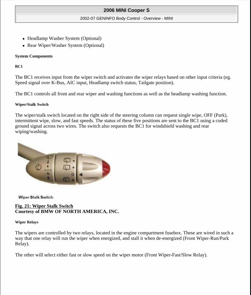
Wiper/Stalk Switch
The wiper/stalk switch located on the right side of the steering column can request single wipe, OFF (Park), intermittent wipe, slow, and fast speeds. The status of these five positions are sent to the BC1 using a coded ground signal across two wires. The switch also requests the BC1 for windshield washing and rear wiping/washing.
Fig. 21: Wiper Stalk Switch Courtesy of BMW OF NORTH AMERICA, INC.
Wiper Relays
The wipers are controlled by two relays, located in the engine compartment fusebox. These are wired in such a way that one relay will run the wiper when energized, and stall it when de-energized (Front Wiper-Run/Park Relay).
The other will select either fast or slow speed on the wiper motor (Front Wiper-Fast/Slow Relay).
2006 MINI Cooper S
2002-07 GENINFO Body Control - Overview - MINI
Microsoft
Tuesday, February 16, 2010 10:04:25 AM Page 25 © 2005 Mitchell Repair Information Company, LLC.

Fig. 22: Wiper Relays Courtesy of BMW OF NORTH AMERICA, INC.
Wiper Motor
The wiper motor and linkage is situated in the air intake plenum area, mounted directly to the body bulkhead. The wiper motor incorporates the reset contact which serves two functions: to park the motor and the block protection feature.
Fig. 23: Locating Wiper Motor Courtesy of BMW OF NORTH AMERICA, INC.
Windshield Washer Pump
The washer pump for the front and rear screen is a single unit with two outlets.
The pump and washer bottle is located in the right front wheel arch area.
Headlamp Wash System
The headlight wash system is available as an option. An external relay in the A post fuse-box is controlled by the BC1. The washer pump and bottle is located in the left front wheel arch area.
The headlamp power wash pump, is controlled by a relay mounted in the passenger compartment fusebox. The BC1 ground controls the relay to activate the headlight washer pump.
2006 MINI Cooper S
2002-07 GENINFO Body Control - Overview - MINI
Microsoft
Tuesday, February 16, 2010 10:04:25 AM Page 26 © 2005 Mitchell Repair Information Company, LLC.

Fig. 24: Locating Headlight Power Wash Pump Courtesy of BMW OF NORTH AMERICA, INC.
AIC (Automatic Interval Control)
In addition to the wiper switch, wiper motor and Body Control Module (BC1) the Automatic Interval Control is made up of the following components:
AIC optical body (prism)
Control unit
Fig. 25: AIC Control Unit Courtesy of BMW OF NORTH AMERICA, INC.
2006 MINI Cooper S
2002-07 GENINFO Body Control - Overview - MINI
Microsoft
Tuesday, February 16, 2010 10:04:25 AM Page 27 © 2005 Mitchell Repair Information Company, LLC.

Fig. 26: Optical Prism Courtesy of BMW OF NORTH AMERICA, INC.
The control unit clips to the prism and can be replaced independently from the optical unit. The AIC control unit contains:
Infrared transmitter and receiver
Heating measuring optics
PE (photo electric) cell
Evaluation electronics
The automatic interval control (AIC) has the task of controlling the frequency of the wipers in relation to the intensity of the rain and/or the wetness of the windshield. The AIC (rain sensor) is an optical system. The unit transmits infrared light and the reflection of the light back from the windshield is then calculated within the control unit.
The AIC optical body, the prism, is firmly installed to the inner side of the windshield underneath the mirror base attachment and is not a serviceable component; it cannot be removed/refitted in the workshop. Replacement windshields are supplied with the AIC prism already fitted. The prism is installed in the center of the windshield near the top.
2006 MINI Cooper S
2002-07 GENINFO Body Control - Overview - MINI
Microsoft
Tuesday, February 16, 2010 10:04:25 AM Page 28 © 2005 Mitchell Repair Information Company, LLC.

Fig. 27: AIC Operation Diagram Courtesy of BMW OF NORTH AMERICA, INC.
Rain/Light Sensor (RLS)
The Rain/Light Sensor is standard equipment, it is installed below the base of the rear view mirror as in other models.
The rain/driving light sensor is an improved version of the first-generation AIC rain sensor.
An additional driving light sensor is integrated into the rain/driving light sensor.
This function is described separately in the vehicle lighting section.
Fig. 28: Rain/Light Sensor (RLS) Components Courtesy of BMW OF NORTH AMERICA, INC.
2006 MINI Cooper S
2002-07 GENINFO Body Control - Overview - MINI
Microsoft
Tuesday, February 16, 2010 10:04:25 AM Page 29 © 2005 Mitchell Repair Information Company, LLC.

Modifications from the first-generation rain sensor:
There are now 4 optical measurement sections instead of 2 which provides improved identification of dirt, salt etc.
Integration of the light sensor function.
K-Bus interface
Flash Programmable EEPROM.
The measuring principle of the RLS is identical to that of the previous rain sensor (AIC, automatic interval control).
The rain detection function is based on the principle of total reflection against the glass-to-air boundary surface:
When the windshield is clean and dry, the infrared light transmitted by the rain/driving light sensor is fully reflected.
When the windshield is wet or dirty in the area of the reflective surfaces, the conditions for total reflectionno longer exist. As a result, less light is reflected.
This change in the signal is evaluated by a microprocessor in the Rain/Light sensor (together with other signals, e.g. speed).
If necessary, a message is sent to the wiper module via the K-Bus.
The wiper module then:
Activates the wipe operation
Determines the wiper speed and the interval duration
2006 MINI Cooper S
2002-07 GENINFO Body Control - Overview - MINI
Microsoft
Tuesday, February 16, 2010 10:04:25 AM Page 30 © 2005 Mitchell Repair Information Company, LLC.

Fig. 29: Rain Detection Function Diagram Courtesy of BMW OF NORTH AMERICA, INC.
Rear Wiper/Washer System
The rear wipe/wash system is relay controlled and operational with the ignition in position 1. The relay for the wiper motor is fixed to the backside of the A post fusebox and cannot be replaced. The rear wiper/washer system includes the following components:
Wiper/Stalk Switch
Rear Wiper Motor
Rear Wiper Relay
Shared Washer Pump
2006 MINI Cooper S
2002-07 GENINFO Body Control - Overview - MINI
Microsoft
Tuesday, February 16, 2010 10:04:25 AM Page 31 © 2005 Mitchell Repair Information Company, LLC.

Fig. 30: Wiper Stalk Switch With Rear Wiper Controls Courtesy of BMW OF NORTH AMERICA, INC.
Fig. 31: Rear Wiper Motor Courtesy of BMW OF NORTH AMERICA, INC.
Fig. 32: Rear Wiper Relay Courtesy of BMW OF NORTH AMERICA, INC.
Principle of Operation
Single Wipe
2006 MINI Cooper S
2002-07 GENINFO Body Control - Overview - MINI
Microsoft
Tuesday, February 16, 2010 10:04:25 AM Page 32 © 2005 Mitchell Repair Information Company, LLC.

Moving the wiper stalk down will initiate a flick wipe. The function of this position is that while the switch is held on, the wiper will run at fast speed continuously. When the switch is released, the wiper will change to slow speed, until the park position is reached.
Intermittent Wipe
The intermittent wipe frequency is dependent on road speed, which the BC1 receives over the K-bus. The delay times and speed classes are:
Intermittent Wipe
The intermittent wipe frequency is dependent on road speed, which the BC1 receives over the K-bus. The delay times and speed classes are:
WIPER SPEED DEPENDENT RELAY
Speeds 1 and 2
Road speed has no influence over wiper speed 1 (Slow).
If the wiper switch is set to speed 2 (Fast) and the vehicle speed falls < 8 km/h the wipers will switch to speed 1.
If the wiper switch is moved while the vehicle is stationary (< 8 km/h) then the speed dependent function is ignored and the wipers will perform as if the vehicle was moving (< 8 km/h). In this way, the customer can over ride speed dependent function if required.
This function can be enabled or disabled using DISplus.
AIC and RLS
(Automatic Interval Control & Rain Light Sensor)
The AIC is activated with the wiper switch in the intermittent position from ignition position 1. If the wiper switch is already in the intermittent position when the ignition is switched to position 1 or 2, AIC will not be active. When the wiper switch is moved from intermittent to OFF and back to the intermittent position, the AIC will be active again.
The BC1 sends the wiper switch position to the AIC via a K-bus telegram. The AIC controls the time interval pauses from zero to infinity depending on the wetness of the windshield. The AIC will transmit a K-bus message every 10 seconds when the intermittent mode is selected if the screen is dry (indicating that the AIC is functional) The time interval of the signal will decrease once water is detected.
If the BC1 does not receive the K-bus telegram for a period greater than 12 seconds, the AIC:
Function will be disabled
Speed (km/h) <8 <32 <64 <92 <128 >128Time (sec) 10 8 6 5 4 3
2006 MINI Cooper S
2002-07 GENINFO Body Control - Overview - MINI
Microsoft
Tuesday, February 16, 2010 10:04:25 AM Page 33 © 2005 Mitchell Repair Information Company, LLC.

Intermittent function will be adopted
A fault code is generated
The AIC system fails, the intermittent wipe function defaults to the same function as a vehicles without AIC.
BC1
A ground signal from the BC1 energizes the wiper relays (both for the front and rear wipers). The BC1 also provides a ground signal for the headlamp washer relay. Washer pump operation (front and rear washers) is controlled by the BC1 through a reversing of polarity to the washer pump.
Inputs to the BC1 include:
Wiper Switch - Front Wiper Speed Request
Front Washer request
Rear Wiper Request
Rear Washer Request
Headlamp Switch (For headlamp wash functions)
Tailgate position Switch (For rear wiper functions)
K-Bus - Vehicle speed
AIC Status
Park Contacts - Front Wiper Motor (Park Position and Stall Protection)
Rear Wiper Motor (Park Position and Stall Protection)
Wiper Stalk Switch
Coded ground signals are input to the BC1 from the Wiper Stalk Switch to accommodate wiper functions. Switched grounds are also provided to request washer (front or rear) and rear wiper activation.
2006 MINI Cooper S
2002-07 GENINFO Body Control - Overview - MINI
Microsoft
Tuesday, February 16, 2010 10:04:25 AM Page 34 © 2005 Mitchell Repair Information Company, LLC.

Fig. 33: Wiper Stalk Switch Input To BC1 Courtesy of BMW OF NORTH AMERICA, INC.
Workshop Hint
If the wiper motor stalls and then becomes free, the relay will not be re-energized until the key is cycled off and then back on.
Wiper Relays
The two Wiper Relays work in conjunction with each other to provide power to the wiper motor for Slow or Fast operation.
Both Relays are powered (Relay Term 86) by fuse F09. The On/Off Relay, a 4 pin relay, receives its energizing ground (Term 85) from the BC1. The Fast/Slow Relay, a 6 pin relay, also receives its energizing ground (Term85) from the BC1. While the On/Off relay functions as a standard on/off type relay, the Fast/Slow relay operates as a switch over type relay.
The at rest state of the On/Off relay is off (no power flowing through the points) and the rest state of the Fast/Slow relay is on (power flowing through one of the point sets to the slow connection of the wiper Motor).
The energized state of the On/Off relay provides power to the fast/slow relay, so that while the fast/slow relay is not energized B+ flows to the slow speed connection on the wiper motor. When the Fast/Slow relay is energized by the BC1, the points are switched over to supply B+ to the Fast speed connection on the wiper motor.
Fig. 34: ON/OFF And FAST/SLOW Wiper Relays For Front Wipers Courtesy of BMW OF NORTH AMERICA, INC.
Wiper Motor
2006 MINI Cooper S
2002-07 GENINFO Body Control - Overview - MINI
Microsoft
Tuesday, February 16, 2010 10:04:26 AM Page 35 © 2005 Mitchell Repair Information Company, LLC.

The Wiper Motor has two B+ connections, one for slow speed operation and one for fast speed. The ground side of the wiper motor includes a reset contact that sends a ground signal to the BC1 once per revolution of the motor. This reset contact is used for park positioning and stall protection.
When the wiper motor is in the park position, the reset contact is an open (High) circuit. The wiper on/off relay will be de-energized if the reset contact does not go High at least once every 18 seconds.
Fig. 35: Wiper Motor Schematic Diagram Courtesy of BMW OF NORTH AMERICA, INC.
Windshield Washer System
The washer pump has two inputs, when it is driven in one direction it feeds water to the front screen and when reversed it feeds water to the rear screen.
At rest, both sides are connected to ground, but when running, the current will flow in either direction. The circuit is protected by a 10A fuse, which requires 15A for 1 second to blow. The normal running current is 4A with a stall current of 7A.
2006 MINI Cooper S
2002-07 GENINFO Body Control - Overview - MINI
Microsoft
Tuesday, February 16, 2010 10:04:26 AM Page 36 © 2005 Mitchell Repair Information Company, LLC.

Fig. 36: Wiper Washer Motor (Left Front Driver Side) Courtesy of BMW OF NORTH AMERICA, INC.
Fig. 37: Washer Fluid Low Level Indicator Courtesy of BMW OF NORTH AMERICA, INC.
Headlamp Washer System
The headlamp power wash pump, is controlled by a relay mounted in the passenger compartment fusebox. A low side switch in the BC1 activates it.
The system will function when the low or high beam lights are on. The headlights are washed with two squirts with a pause of 5 seconds between wash cycles. After activation a 10-minute inhibit function is active - this can be over-ridden by activating the washer switch four times in succession.
2006 MINI Cooper S
2002-07 GENINFO Body Control - Overview - MINI
Microsoft
Tuesday, February 16, 2010 10:04:26 AM Page 37 © 2005 Mitchell Repair Information Company, LLC.

Fig. 38: Locating Headlight Power Wash Relay Courtesy of BMW OF NORTH AMERICA, INC.
Rear Wipe/Wash System
When the rear wiper switch is activated, the rear wiper relay output is pulled low, energizing the relay, switching the motor on.
The BC1 receives a low signal (switched to ground) when the wiper is parked. Time between park events is monitored to detect stalling or freezing of the mechanism.
The wiper motor relay is energized until the wiper has completed three wipes (counted by monitoring the rear park switch). Once this continuous phase has finished, the wiper switches to intermittent operation as follows:
If the front wipers are on intermittent (AIC not fitted), slow or fast: The ratio of front wipes to rear wipes is 3:1 with rear wiper start synchronized with the front wiper start.
If front wipers are off or on intermittent (AIC fitted), then one wipe for every 10 ± 1 sec after start of previous rear wipe cycle will apply.
The BC1 monitors the park contact within the rear motor and will deactivate the relay if the signal is not received within 5 seconds of activating the relay - this prevents damage to the motor in the event of the wiper jamming.
The rear wiper system is disabled with the tailgate open. The BC1 looks at the tailgate position switch after receiving a request for rear wiper activation and delays the request if the tailgate is open. Turning the rear wiper switch off then back on will over-ride the tailgate position. Rear wiper operation is also possible at speeds above 6km/h regardless of tailgate position.
Notes:
INTERIOR LIGHTING
The vehicle interior lighting of the MINI is controlled via the Body Control Module (BC1) and features the
2006 MINI Cooper S
2002-07 GENINFO Body Control - Overview - MINI
Microsoft
Tuesday, February 16, 2010 10:04:26 AM Page 38 © 2005 Mitchell Repair Information Company, LLC.
following lights:
Interior lamp
Luggage compartment lamp
Glove Box Lighting
Ashtray Lighting
Map reading lamps (Option)
Sun visor vanity lamps (Option)
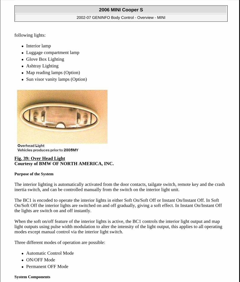
Fig. 39: Over Head Light Courtesy of BMW OF NORTH AMERICA, INC.
Purpose of the System
The interior lighting is automatically activated from the door contacts, tailgate switch, remote key and the crash inertia switch, and can be controlled manually from the switch on the interior light unit.
The BC1 is encoded to operate the interior lights in either Soft On/Soft Off or Instant On/Instant Off. In Soft On/Soft Off the interior lights are switched on and off gradually, giving a soft effect. In Instant On/Instant Off the lights are switch on and off instantly.
When the soft on/off feature of the interior lights is active, the BC1 controls the interior light output and map light outputs using pulse width modulation to alter the intensity of the light output, this applies to all operating modes except manual control via the interior light switch.
Three different modes of operation are possible:
Automatic Control Mode
ON/OFF Mode
Permanent OFF Mode
System Components
2006 MINI Cooper S
2002-07 GENINFO Body Control - Overview - MINI
Microsoft
Tuesday, February 16, 2010 10:04:26 AM Page 39 © 2005 Mitchell Repair Information Company, LLC.

Interior Lighting is controlled through four lighting circuits. Three circuits are BC1 controlled, the fourth, Ashtray Lighting, is controlled via the External Light Switch.
BC1 CONTROLLED INTERIOR LIGHTING CIRCUITS
BC1
The BC1 based on its inputs controls the output of the interior lighting through pulse width modulated voltage. All decisions regarding interior light availability are made in the processing of the BC1. The BC1 controls interior light on time and shut-off to conserve battery power.
Principle of Operation
Automatic Control Mode
A number of control conditions apply when the interior lights are in the automatic mode. The interior lights can be on for several different time periods depending on the trigger source. The OFF conditions are only delayed by the ramp down duration (2.6 seconds).
On Conditions-16 Minutes
One or more doors are opened
Tailgate is opened
Inertia switch triggered with ignition in position 1 or 2
MRS4 System triggered
On Conditions - 20 Seconds
External unlock (either with the key or remote transmitter)
Ignition switched to position 0 from 1
On Conditions -10 Seconds
External remote transmitter lock with vehicle already locked and alarm armed (Locating feature).
Off Conditions
External lock (either with the key or remote transmitter)
If any door or tailgate is open for more than 16 minutes
Inertia switch reset
16 minutes after the last valid on condition
Interior light switch pressed when interior lights are on
All doors and tailgate shut with ignition status either on position 1 or 2 (If the interior lights are not activated by the interior light switch)
All doors and tailgate shut with the ignition in the 0 position (delay time = 20 seconds)
When in automatic mode the newest request for action will over-ride the current state. Also, the power saving
Interior Light (Overhead) Footwell Lights
Left and Right Side Reading Lamps Sun Visor Lighting Glove Box Lighting
Luggage Compartment Lighting
2006 MINI Cooper S
2002-07 GENINFO Body Control - Overview - MINI
Microsoft
Tuesday, February 16, 2010 10:04:26 AM Page 40 © 2005 Mitchell Repair Information Company, LLC.

mode (16 minutes) will be cancelled when all of the doors or the tailgate are shut or if any other valid ON/OFF signal is received.
Interior Light Switch (ON/OFF Mode)
The interior light switch can be used to turn the interior lights ON and OFF. The interior light switch will operate at all times, except when the alarm is armed. If the interior light switch is used to turn on the interior light, the light stays on for 16 minutes, regardless of the state or change of state of the ignition switch. The interior light will fade off when the vehicle is externally locked or key is in not in the KL0 position.
Permanent Off Mode
The interior light output will always be able to assume permanent OFF mode. Pressing the interior light switch and holding it for more than 5 seconds will put the interior light into the permanent OFF mode.
In permanent OFF mode, all on conditions except momentary interior light switch operations are ignored. To return the interior lights to the automatic mode press the interior light switch again. If the interior lights are in permanent OFF mode, triggering of the inertia switch from ignition position 1 returns the interior light to the automatic control mode.
Notes:
EXTERIOR LIGHTING
The BC1 controls all Exterior Lighting functions of the MINI except the reverse lights. There are no back-up, substitute lighting or warning indications in the event of a bulb failure.
Purpose of the System
The BC1 provides control over exterior lighting and illumination of instrumentation indicators for turn signals and high beams. The exterior lighting functions of the BC1 also provide "Follow-Me-Home" Lighting and emergency operation of limited lighting functions in the case of BC1 failure.
These light functions are controlled by the BC1:
Headlights
Tail Lights
Brake Lights
Turn Signals
Side Marker Lights
Auxiliary Lights
Fog Lights
Directional Indicators
High Beam Indicator
License Plate Lights
2006 MINI Cooper S
2002-07 GENINFO Body Control - Overview - MINI
Microsoft
Tuesday, February 16, 2010 10:04:26 AM Page 41 © 2005 Mitchell Repair Information Company, LLC.
Hazard Warning Lights
Flash to Pass Lights
The BC1 does not control, but signals for activation the optional Xenon Lights.
Fig. 40: Head Lights Courtesy of BMW OF NORTH AMERICA, INC.
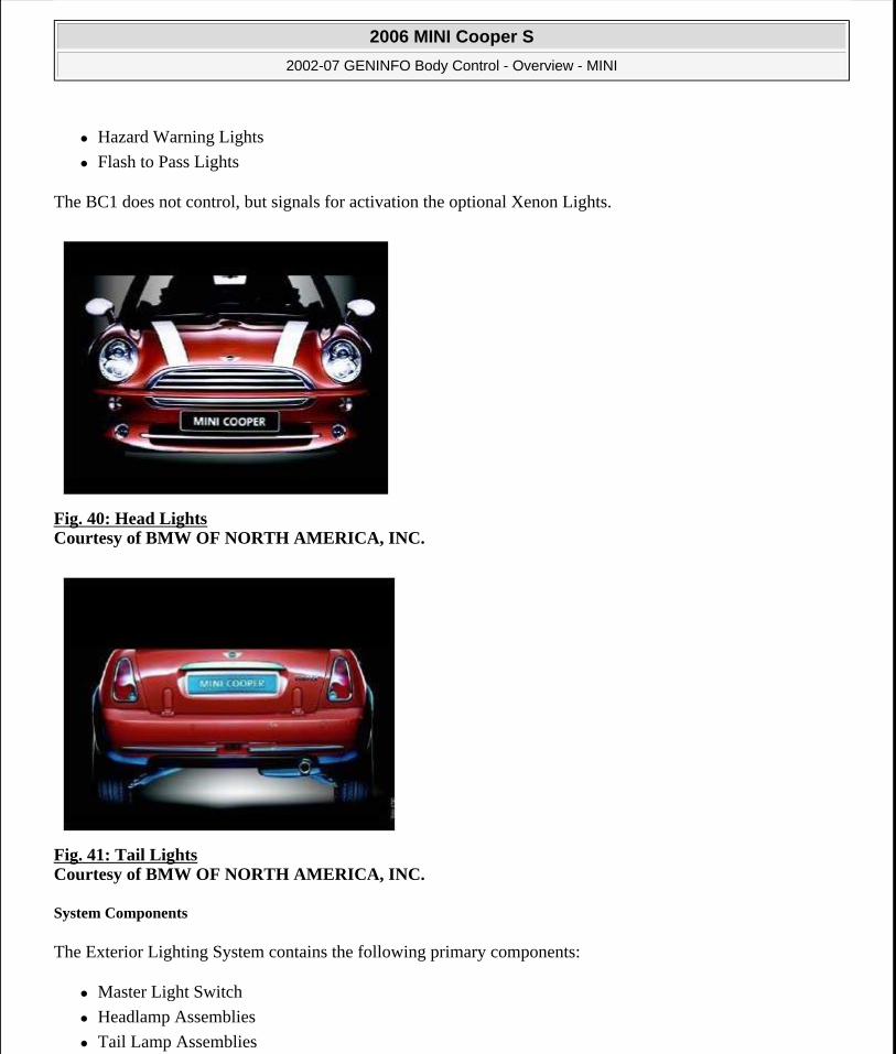
Fig. 41: Tail Lights Courtesy of BMW OF NORTH AMERICA, INC.
System Components
The Exterior Lighting System contains the following primary components:
Master Light Switch
Headlamp Assemblies
Tail Lamp Assemblies
2006 MINI Cooper S
2002-07 GENINFO Body Control - Overview - MINI
Microsoft
Tuesday, February 16, 2010 10:04:26 AM Page 42 © 2005 Mitchell Repair Information Company, LLC.

Front Turn Signal Assemblies
Fog Lights and Fog Light Relay (Optional)
Xenon Light Assemblies (Optional, Includes DHL)
Main Light Switch
The Main Light Switch is located to the left of the steering column. Functions of the switch are:
Low Beam Headlamps (automatic on)
High Beam Headlamps (and Flash to Pass)
Turn Signals (Left and Right)
Turn Signal Indicators
Parking Lights
Trip Computer Functions
Fig. 42: Main Light Switch Courtesy of BMW OF NORTH AMERICA, INC.
Fig. 43: Main Light Switch (From 1/2005) Courtesy of BMW OF NORTH AMERICA, INC.
Headlamp Assemblies
The Headlamp Assemblies contain the Low Beam and High Beam bulbs.
Both bulbs are 12 H7 type bulbs. The bulbs are replaceable from the rear of the headlamp assemblies.
2006 MINI Cooper S
2002-07 GENINFO Body Control - Overview - MINI
Microsoft
Tuesday, February 16, 2010 10:04:26 AM Page 43 © 2005 Mitchell Repair Information Company, LLC.

To remove the bulbs:
remove cap (1) from rear of high beam bulb
disconnect connector (2)
release retaining clip (3)
remove bulb (4).
Fig. 44: Headlamp Assembly Courtesy of BMW OF NORTH AMERICA, INC.
Xenon Lights (Optional)
The automotive industry/press often identify xenon lighting systems as HID (high intensity discharge) systems. Xenon headlight technology was first introduced to the US market exclusively on the E32 750iL in 1993.
Xenon headlight systems have evolved and their availability as optional equipment has spread throughout the vehicle lineups. Blue/White in color and using ellipsoidal technology Xenon headlights provide improved nighttime visibility in all driving conditions compared with traditional Halogen bulb headlights.
Xenon headlights provide the following benefits:
Longer bulb life. Xenon bulbs will last from 3 to 5 times longer than halogen.
More light output. Xenon headlights produce from 2.5 to 3 times more lumens than halogen.
Blue/White light (simulates natural daylight). Xenon bulbs produce a blue/white light while halogen bulbs produce a yellow light. The light color of a light source is measured in color temperature (not to be confused with thermal temperature). Color temperature is measured in Kelvin (K). The higher the color temperature the whiter the light.
Natural daylight = 4,500 to 5,000 K
Xenon headlights = 4,000 to 4,500 K
Halogen headlights = 3,200 K (yellow in color)
Better driving visibility. The combination of higher lumens and higher color temperature provide a superior lighting source. The beam is wider and brighter in front of the vehicle than conventional halogen
2006 MINI Cooper S
2002-07 GENINFO Body Control - Overview - MINI
Microsoft
Tuesday, February 16, 2010 10:04:26 AM Page 44 © 2005 Mitchell Repair Information Company, LLC.

bulbs improving safety and driver comfort.
Lower operating temperature.
Lower power consumption.
Xenon bulbs are identified as D-2S (D=Discharge). Xenon bulbs illuminate when an arc of electrical current is established between two electrodes in the bulb. The xenon gas sealed in the bulb reacts to the electrical excitation and heat generated by the current flow. The distinct bluish/white brilliant light is the result of the xenon gas reacting to the controlled current flow.
Fig. 45: Xenon Lights (Optional) Courtesy of BMW OF NORTH AMERICA, INC.
Phases of Bulb Operation
Starting Phase: The bulb requires an initial high voltage starting pulse of 18-25kV to establish the arc.
Warm Up Phase: Once the arc is established the power supply to the bulb is regulated to 2.6A generating a lamp output of 75 watts. This is the period of operation where the xenon gas begins to brightly illuminate. The warm up phase stabilizes the environment in the bulb ensuring continual current flow across the electrodes.
Continuous Phase: Once the warm up phase is completed, the system switches to a continuous mode of operation. The supply voltage for the bulb is reduced and the operating power required for continual bulb illumination is reduced to 35 watts which is less than a conventional halogen bulb.
Functional Description
To regulate the power supply to the bulbs, additional components are required. The xenon control modules (1 per light) receive operating power from the BC1 when the headlights are switched on. The xenon control modules provide the regulated power supply to illuminate the bulbs through their phases of operation. The igniters establish the electric arcs. Integral coils generate the initial high voltage starting pulses from the control module provided starting voltage. Thereafter they provide a closed circuit for the regulated power output from
2006 MINI Cooper S
2002-07 GENINFO Body Control - Overview - MINI
Microsoft
Tuesday, February 16, 2010 10:04:26 AM Page 45 © 2005 Mitchell Repair Information Company, LLC.

the control modules.
Fig. 46: Functional Description Of Bulb Courtesy of BMW OF NORTH AMERICA, INC.
Xenon Headlight Testing
The Xenon control modules are supplies battery voltage from the BC1 when the low beams are requested. The bulb operation should be checked with an amperage clamp. Normal amperage flow should be between 3-5 Amps.
Dynamic Headlight Adjustment (DHL - Xenon Only)
Cars equipped with Xenon headlights require automatic headlight aim control; this necessitates a separate control module to carry out automatic adjustment of the headlights.
With automatic headlight levelling, the load status and its changes are recorded by means of two height level sensors (potentiometers) located at the front and rear axles. The information from these sensors is communicated back to the DHL module.
Each headlight has electrically driven linear stepper motors, which are connected to the headlamp inserts in such a way that their movement changes the range of the headlamp.
WARNING: Xenon headlight control systems generate high output voltage. Prior to headlight removal or testing observe the vehicle warning labels and be cautious by following safeguards to prevent accidental injury.
2006 MINI Cooper S
2002-07 GENINFO Body Control - Overview - MINI
Microsoft
Tuesday, February 16, 2010 10:04:26 AM Page 46 © 2005 Mitchell Repair Information Company, LLC.

Fig. 47: DHL Head Light Adjustment Module Courtesy of BMW OF NORTH AMERICA, INC.
Fig. 48: Headlight Adjustments Components Courtesy of BMW OF NORTH AMERICA, INC.
2006 MINI Cooper S
2002-07 GENINFO Body Control - Overview - MINI
Microsoft
Tuesday, February 16, 2010 10:04:26 AM Page 47 © 2005 Mitchell Repair Information Company, LLC.

Fig. 49: Front DHL Sensor Courtesy of BMW OF NORTH AMERICA, INC.
Fig. 50: Rear DHL Sensor Courtesy of BMW OF NORTH AMERICA, INC.
Workshop Hint
Headlamp Adjustments are performed using special tool #63 2 100.
Fit tool to the adjustment screw (1) and lock tool to adjustment screw by sliding (2) in direction shown.
Close hood, ensuring the service tool is routed correctly between the hood and wheel arch liner.
Principle of Operation
Headlights
Low beams are switched on when the main light switch is set to position 2 with the ignition switch in position 2. Pulling the low beam/high beam switch towards the driver with the ignition in position 1 or 2 activates the headlight flasher (flash to pass). Flash to pass is active with the low beams OFF or ON.
2006 MINI Cooper S
2002-07 GENINFO Body Control - Overview - MINI
Microsoft
Tuesday, February 16, 2010 10:04:26 AM Page 48 © 2005 Mitchell Repair Information Company, LLC.

High beam lights are activated by pulling the low beam/high beam switch toward the driver until its end position is reached. Pulling the switch a second time de-activates the high beams. The low beam lights must be on and the ignition switch in position 2 for high beam activation.
Operation of the optional Xenon headlights is the same.
Tail Lights
The Tail Lights and license plate lights are ON anytime the main light switch is in position 1 or 2. It is not necessary for the ignition to be on.
Brake Lights
The Brake Lights are triggered by the hall-effect brake light switch signal to the BC1. The ignition must be ON for the brake lights to be active. Complete failure of the brake light switch will cause the brake lights to be ON anytime the ignition is on.
The third brake light is an LED type and is serviced as a complete unit only.
Turn Signals
Movement of the turn signal stalk up or down will activate the Left/Right turn signals with the ignition on. Placement of the stalk switch up or down with the ignition off will activate parking lights only on the side requested.
Flashing of the turn signals is controlled by the BC1.
The left hand and right hand direction indicator lamps in the instrument cluster will always be synchronized with the respective vehicle direction indicators. The Body Control Module (BC1) controls operation of the indicator LED in the cluster via the K-bus.
Hazard Warning Lights
The hazard warning function is activated via the hazard warning switch integrated into the instrument cluster, the direction indicator lamps will be turned on (flash cycle). The lamps are turned off when the hazard switch is reselected regardless of the ignition switch position and the direction indicator switches.
Fog Lights
Front fog lights can only be switched on when the side lights or low beam headlights are switched on. The front fog lamps are powered via an external relay located in the engine compartment fuse box. The Body Control Module (BC1) controls the front fog light relay. The front fog light indicator in the fog light switch is driven from the output of the relay.
Rain/Driving-Light Sensor (RLS)
The new RLS replaces the familiar Rain Sensor already in use. The RLS now has the added functions of monitoring ambient light conditions to influence the operation of the headlights.
2006 MINI Cooper S
2002-07 GENINFO Body Control - Overview - MINI
Microsoft
Tuesday, February 16, 2010 10:04:26 AM Page 49 © 2005 Mitchell Repair Information Company, LLC.

The driving lights (headlights) are turned on and off automatically based on input from the RLS depending upon ambient light conditions.
Fig. 51: Rain/Driving-Light Sensor (RLS) Courtesy of BMW OF NORTH AMERICA, INC.
The new RLS contains two additional optical sensors have been integrated in the sensor housing. The RLS continues to use similar rain sensing electronics as used on the previous AIC system. The two additional light sensors are used for headlight operation.
The two sensors have the following function:
Sensor number 1 is a surrounding-light sensor that records the light intensity in a wide angle above the vehicle.
Sensor number 2 is a frontal-light sensor that records the light intensity in a narrow angle in front of the vehicle. A processor measures and determines which sensor is switched on.
The following conditions are monitored by the (RLS):
Dawn/dusk
Darkness
Driving through a tunnel
Precipitation such as rain or snow
If wiper switch condition is on, The RLS in the E46 transmits the information thorough the K-bus to the central light switch. (LSZ).
If the RLS switch position("A") on the LSZ has been selected, the exterior and instrument lights are activated by the LSZ under the following conditions:
One of the above RLS conditions is satisfied.
The front fog lights are switched on.
NOTE: When the wiper switch is in the intermittent position, The RLS knows the switch is on by the frequency of the windshield wipers. (The frequency for the intermittent wipers is 15 wiping cycles per minute. If the wiper switch is in
2006 MINI Cooper S
2002-07 GENINFO Body Control - Overview - MINI
Microsoft
Tuesday, February 16, 2010 10:04:26 AM Page 50 © 2005 Mitchell Repair Information Company, LLC.

Fig. 52: [RLS Sensor] Courtesy of BMW OF NORTH AMERICA, INC.
In addition, the lights are switched on in the event of the following malfunctions.
The RLS has detected a sensor fault.
Communication between the RLS and the LSZ is disturbed.
The following lights are switched by the LSZ:
Terminal R turns on the parking light, the low beam headlight, the license plate light and the instrument lights.
Terminal 15 turns on the parking light, the low beam headlights, the license plate light. In order to switch the parking light on the LSZ switch must be set to parking light position on.
With the ignition switch in the "0" position, the exterior and instrument lights are switched off.
The sensitivity of the RLS can be adjusted by means of the car memory function.
Safety Notice: During bad weather and fog the driver must switch on the fog lights manually. The automatic driving-light control will not turn the fog lights on during bad weather conditions.
Follow-Me-Home Lights
To activate the follow-me-home function, with the low beam on, turn the ignition to position 0 or 1 from position 2 and switch the master light switch to the off position. The low beams will remain on for 30 seconds, then turn off.
Crash Activation
position I or II the RLS knows the wipers are switched on permanently.
NOTE: If the front fog light is switched on and one of the above mentioned RLS conditions is satisfied, the exterior lights will only go out after the front fog lights have been turned off.
2006 MINI Cooper S
2002-07 GENINFO Body Control - Overview - MINI
Microsoft
Tuesday, February 16, 2010 10:04:26 AM Page 51 © 2005 Mitchell Repair Information Company, LLC.

The direction indicator lights will be turned on (flash cycle), when the vehicle inertia switch is triggered. The direction indicators will continue to flash until the hazard warning switch is operated which will turn off the direction indicator lights.
Reverse Lights
Control of the Reverse Lights is handled by the reverse light switch in the manual transmission or the ECVT. B+ is supplied through the switch when reverse gear is engaged.
Emergency Light Operating Mode
An emergency backup hardware circuit completely independent of the BC1 will ensure certain lights can function in the event of a failure within the BC1.
During normal operation a cycling frequency from the BC1 deactivates this emergency circuit. This cycling frequency should be at least 15 Hz. Emergency operation is initiated if this does not take place.
The emergency mode provides the following lights from ignition position 1 regardless of the light switch position:
Front sidelights
Rear sidelights
Low beam lamps
Left and right brake lamps (when the brake switch is active)
The following functions will not operate in Emergency Mode:
Direction indicator lamps
Hazard warning lamps
Main beam lamps
Front fog lamps
Communication via the K-bus
Instrument/switch illumination
Diagnostics
Diagnostics are carried out using the GT1 or DISplus.
DWA
The DWA Anti-theft Warning System is a dealer installed option on the MINI.
Purpose of the System
The anti-theft warning system (DWA) monitors the contacts on the doors, tailgate and bonnet as well as the
2006 MINI Cooper S
2002-07 GENINFO Body Control - Overview - MINI
Microsoft
Tuesday, February 16, 2010 10:04:26 AM Page 52 © 2005 Mitchell Repair Information Company, LLC.

status of the ignition switch terminals, tilt sensor and the interior protection.
The DWA system is controlled by the Body Control Module (BC1), which like the auxiliary powered siren is installed in a place that is difficult to access, this prevents interference with alarm operation.
System Components
In addition to the BC1 the DWA system consists of the following components:
Door, Hood and Tailgate Switches
DWA LED
Tilt Sensor
UIS Sensor
Auxiliary Powered Siren
Fig. 53: DWA LED (Before 1/2005) Courtesy of BMW OF NORTH AMERICA, INC.
Fig. 54: Hood Switch Courtesy of BMW OF NORTH AMERICA, INC.
Door Switches
The BC1 uses input from the same door position and lock/unlock micro switches used for door status and position by the Central Lock System.
2006 MINI Cooper S
2002-07 GENINFO Body Control - Overview - MINI
Microsoft
Tuesday, February 16, 2010 10:04:26 AM Page 53 © 2005 Mitchell Repair Information Company, LLC.

Hood Switch
The hood switch is a micro switch situated in the hood opening mechanism on the left-hand side of the engine compartment (viewed from the front bumper).
Tailgate Switch
Tailgate position status is received by the BC1 from the tailgate release actuator.
Tilt Sensor
The tilt sensor is situated on the left side of the luggage compartment. Its purpose is to measure the vehicle parked angle when the DWA is armed.
The tilt sensor wire uses four wires:
DWA 12V - supply voltage from the BC1 to the tilt sensor.
NG - switched ground output to the BC1 used to set off alarm.
STDWA from BC1 used to arm/disarm alarm
KL 31 - ground
Fig. 55: Tilt Sensor Courtesy of BMW OF NORTH AMERICA, INC.
DWA LED
The DWA LED located on the wiper or headlight stalk flashes to provide information about DWA status. The LED had 4 flash patterns:
Confidence Flash
All the time the alarm is armed the LED will flash on for 10ms with a 1 second delay until the next flash.
2006 MINI Cooper S
2002-07 GENINFO Body Control - Overview - MINI
Microsoft
Tuesday, February 16, 2010 10:04:26 AM Page 54 © 2005 Mitchell Repair Information Company, LLC.

Fig. 56: Confidence Flash Patterns Courtesy of BMW OF NORTH AMERICA, INC.
Volumetric Flash
Pressing the remote or locking the car one time activates Volumetric Arming, the monitoring of all contacts plus the tilt and UIS sensor.
For 10 seconds after Volumetric arming the LED will flash rapidly (8hz), 10ms on with only 125ms between flashes.
After the 10 second period the LED will flash in the Confidence Mode.
Fig. 57: Volumetric Flash Patterns Courtesy of BMW OF NORTH AMERICA, INC.
Perimeter Flash
Pressing the lock button twice in two seconds arms the DWA in the Perimeter mode (only the doors, hood, and tailgate contacts monitored). After Perimeter arming the LED will flash rapidly, 10ms on with 125ms between flashes for 1 second, then a 1 second pause, followed by the rapid flashing. At the end of this 10 second sequence the LED will flash in the Confidence Mode.
2006 MINI Cooper S
2002-07 GENINFO Body Control - Overview - MINI
Microsoft
Tuesday, February 16, 2010 10:04:26 AM Page 55 © 2005 Mitchell Repair Information Company, LLC.

Fig. 58: Perimeter Flash Patterns Courtesy of BMW OF NORTH AMERICA, INC.
Tamper Flash
If the alarm has been triggered, the Tamper Flash pattern will be given during disarming. The tamper flash pattern is a slow 200ms on 200ms off pattern.
Fig. 59: Tamper Flash Patterns Courtesy of BMW OF NORTH AMERICA, INC.
UIS Sensor (coupe only)
The UIS Sensor (Ultrasonic) is mounted at the rear of the vehicle on the headliner. Every time the DWA is armed the UIS sensor adapts to whatever objects are stationary in the interior.
The sensor emits ultra sonic waves in a programmed timed cycle and receives echoes of the returning waves. The UIS amplifies the returned sound wave signals and compares them with the transmitted waves. Similar echoes received indicate no movement is detected. Inconsistent or altered returned signals indicate motion in the interior. When motion is detected the UIS changes to a constant rather than timed program and compares returning echoes. If inconsistencies are still present the BC1 is notified of the motion.
Microwave Sensor (convertibles only)
The R52 MINI Convertible incorporates 4 microwave sensors for interior protection.
2006 MINI Cooper S
2002-07 GENINFO Body Control - Overview - MINI
Microsoft
Tuesday, February 16, 2010 10:04:26 AM Page 56 © 2005 Mitchell Repair Information Company, LLC.

Fig. 60: Microwave Sensor (Convertibles Only) Courtesy of BMW OF NORTH AMERICA, INC.
Auxiliary Powered Siren
The auxiliary powered siren is situated in the left hand rear of the engine bay (viewed from the front bumper). The siren contains electronic circuitry for producing the warning tone when the alarm is triggered. The siren also contains a rechargeable battery that is used to power the siren when the alarm is triggered.
In the armed state the auxiliary powered siren is armed by the BC1 holding the arming line to ground, if the power to the BC1 is lost the arm line will be released, which will send power to the auxiliary powered siren. This will cause the auxiliary powered siren to go into its internal triggering sequence.
Fig. 61: Auxiliary Powered Siren Courtesy of BMW OF NORTH AMERICA, INC.
Principle of Operation
Arming
2006 MINI Cooper S
2002-07 GENINFO Body Control - Overview - MINI
Microsoft
Tuesday, February 16, 2010 10:04:26 AM Page 57 © 2005 Mitchell Repair Information Company, LLC.

The following two actions are both regarded as arm actions:
Pressing the lock button on the remote
Turning the door lock to the lock position.
The DWA will be Volumetric armed by the first arm action. Volumetric arming is confirmed by rapid flashing of the DWA LED.
Two identical arming actions occurring sequentially within two seconds will put the DWA into Perimeter mode. Perimeter arming is confirmed by blinking of the DWA LED.
Any further arm actions within two seconds will have no effect on the DWA. Following the two seconds, the DWA will ignore any key arm actions. However any further remote arm actions will turn on the interior light for a period of ten seconds. This feature provides a way of locating the car in a large parking lot.
The BC1 will briefly flash the turn signals three times when the car is locked from the outside and the DWA is armed.
Arming with a Contact Open
If the DWA is armed with the passenger door, tailgate or bonnet open the BC1 will not flash the LED in the relevant mode for the first 10-seconds after arming - this is to indicate to the owner a contact is not closed - after this the LED will flash in confidence mode. The BC1 will also not activate the interior protection and tilt sensor. If the contact is closed after the DWA is armed the LED will flash for 10-seconds in the relevant mode.
Arming with a Window Open
The BC1 uses the current monitoring function for the windows to identify whether the window is in the closed position. If the window is identified as not closed the BC1 will deactivate just the interior protection system.
Disarming
The DWA is disarmed by pressing the unlock button on the remote, turning the door lock to the unlock position or through reading the transponder by turning the ignition lock to the terminal R or 15 position. The DWA will signal that it has been successfully disarmed when the DWA LED stops flashing in confidence mode. If the DWA is triggered then disarming will silence the alarm sounder.
If the DWA has been triggered or is triggering then when it is disarmed the DWA LED will alert the driver to this fact by flashing in Tamper mode. This tamper flash will be terminated when terminal R or terminal 15 goes high or if the alarm is armed again. If the disarm request is made when the DWA is triggering then disarming the trigger cycle will be terminated and the auxiliary powered siren will be silenced and the hazard warning lamps turned off.
Alarm Triggering
The DWA is triggered when any one of the following states are detected:
2006 MINI Cooper S
2002-07 GENINFO Body Control - Overview - MINI
Microsoft
Tuesday, February 16, 2010 10:04:26 AM Page 58 © 2005 Mitchell Repair Information Company, LLC.

Ignition ON (When alarm system is not disarmed)
Hood Open
Tailgate Open
Driver's Door Open
Passenger Door Open
Tilt Sensor Triggered (When Armed)
UIS Triggered (When Armed)
When the DWA is triggered the auxiliary powered siren and the hazard warning lamps will be activated for a period of 30 seconds. Any additional disturbances that occur during trigger duration will not extend its duration.
At the end of the trigger duration the DWA will return to the Perimeter armed state. If the DWA was originally Volumetric armed then provided the tailgate and the two doors are closed it will return to that state. There will be a delay of sensor settle time before the volumetric or the tilt sensors are valid trigger sources. Only new disturbances will trigger the alarm, such as a closed door that subsequently opens. If a door is left open it will not re-trigger the alarm unless it is closed and then re-opened.
Also there is a limit to the number of triggers that are allowed in one setting period. This is a limit on the total number of triggers regardless of the source. If the total number of triggers meets this limit there will be no more triggers in that setting period.
2006 MINI Cooper S
2002-07 GENINFO Body Control - Overview - MINI
Microsoft
Tuesday, February 16, 2010 10:04:26 AM Page 59 © 2005 Mitchell Repair Information Company, LLC.