mini lathe bv20 (like)
DESCRIPTION
Mini Lathe bv20 (like)TRANSCRIPT

OPERATOR'S MANUAL
BV20-1 (IMPERIAL MACHINE)
Warren Machine Tools Ltd Warco House, Fisher Lane, Chiddingfold,Surrey GU84TD
Tel: 01428 682929 Fax: 01428 685870 E-mail: [email protected]
Web:www.warco.co.uk

- 1 -
NOTE The information contained in this handbook is intended as a guide to the operation of these machines and does not form part of any contract. The data it contains has been obtained from the machine manufacturer and from other sources. Whilst every effort has been made to ensure the accuracy of these transcriptions it would be impracticable to verify each and every item. Furthermore, development of the machine may mean that the equipment supplied may differ in detail from the descriptions herein. The responsibility therefore lies with the user to satisfy himself that the equipment or process described is suitable for the purpose intended.
LIMITED WARRANTY
Warren Machine Tools Ltd. Makes every effort to assure that its products meet high quality and durability standards and warrants to the original retail consumer/purchaser of our products that each product be free from defects in materials and workmanship as follow: 1 YEAR LIMITED WARRANTY ON ALL PRODUCTS UNLESS SPECIFIED OTHERWISE. This Warranty does not apply to defects due directly or indirectly to misuse, abuse, negligence or accidents, normal wear-and tear, repair or alterations outside our facilities, or to a lack of maintenance. We shall in no event be liable for death, injuries to persons or property or for incidental, contingent, special, or consequential damages arising from the use of our products. To take advantage of this warranty, the product or part must be returned to us for examination, postage prepaid. Proof of purchase date and an explanation of the complaint must accompany the merchandise. If our inspection discloses a defect, we will either repair or replace the product, or refund the purchases price if we cannot readily and quickly provide a repair or replacement, if you are willing to accept a refund. We will return repaired product or replacement at WARCO’S expense, but if it is determined there in no defect, or that the defect resulted from causes not within the scope of WARCO’S warranty, then the user must bear the cost of storing and returning the product. The manufacturers reserve the right to change specifications at any time as they continually strive to achieve better quality equipment.
Copyright. The copyright of this instruction book is the property of Warren Machine Tools (Guildford) Ltd and may not be reproduced or copied without prior consent of Warren Machine Tools (Guildford) Ltd.

- 2 -
1. This machine is designed and intended for use by properly trained and experienced personnel only. If you are not familiar with the proper safe use of mills, do not use this machine until proper training and knowledge has been obtained. 2. Keep guards in place. Safety guards must be kept in place and in working order. 3. Remove adjusting keys and wrenches. Before turning on machine, check to see that any adjusting wrenches are removed from the tool. 4. Reduce the risk of unintentional starting. Make sure switch is in the OFF position before plugging in the tool. 5. Do not force tool. Always use a tool at the rate for which it was designed. 6. Use the right tool. Do not force a tool or attachment to do a job for which it was not designed. 7. Maintain tools with care. Keep tools sharp and clean for best and safest performance. Follow instructions for lubrication and changing accessories. 8. Always disconnect the machine from the power source before adjusting or servicing. 9. Check for damaged parts. Check for alignment of moving parts, breakage of parts, mounting, and any other condition that may affect the tools operation. A guard or any part that is damaged should be repaired or replaced. 10. Turn power off. Never leave a machine unattended. Do not leave a machine until it comes to a complete stop. 11. Keep work area clean, Cluttered areas and bench invite accidents.
12. Do not use in a dangerous environment. Do not use machines in damp or wet locations, or expose them to rain. Keep work area well lighted. 13. Keep children and visitors away. All visitors should be kept a safe distance from the work area. 14. Make the workshop child proof. Use padlocks, master switches, and remove starter keys. 15. Wear proper apparel. Loose clothing, gloves, neckties, rings, bracelets, or other jewelry may get caught in moving parts. Non-slip footwear is recommended. Wear protective hair covering to contain long hair. Do not wear any type of glove. 16. Always use safety glasses. Every day glasses only have impact resistant lenses; they are not safety glasses. 17. Do not overreach. Keep proper footing and balance at all times. 18. Don not put hands near the cutter while the machine is operating. 19. Do not perform any set-up work while machine is operating. 20. Read and understand all warnings posted on the machine. 21. This manual is intended to familiarize you with the technical aspects of this mill. It is not nor was it intended to be a training manual. 22. Failure to comply with all of these warnings may result in serious injury. 23. Some dust created by power sanding, sawing, grinding, drilling and other construction activities contains chemicals known to cause cancer, birth defects or other reproductive harm.
WARNING! Read and understand the entire instructionmanual before attempting set-up oroperation of this drilling machine!

- 3 -
SPECIFICATIONS:
BV20-1
Capacities: Swing Over Bed 200 mm 8” Swing Over Cross Slide 115 mm 4-3/5” Distance Between Centers 330 mm 13”
Headstock:
Hole Through Spindle 20mm 4/5” Taper in Spindle Nose MT3 MT3
Number of Spindle Speeds 6 6 Range of Spindle Speeds 140-1710r.p.m. 140-1710r.p.m
Feeding and Threading: Number of Metric Threads 9 9 Range of Metric Threads 0.4~2mm 0.4~2mm
Number of Imperial Threads 13 13 Range of Imperial Threads 8-32TPI 8-32TPI Range of Longitudinal Feed 0.002-0.006in/r 0.002-0.006in/r
Compound and Carriage: Tool Post Type 4-Way 4-Way
Maximum Compound Slide Travel 70mm 2-4/5” Maximum Cross Slide Travel 115mm 4-3/5 Maximum Carriage Travel 350mm 16” Tailstock:
Tailstock Spindle Travel 20mm 4/5” Taper in Tailstock Spindle MT2 MT2
Miscellaneous: Main Motor 3/4HP, 1PH, 240V Dimension: Length 1050mm 42” Width 580mm 23” Height 550mm 22” Weight 105KGS 231LBS

- 4 -
TABLE OF CONTENTS
LIMITED WARRANTY………………… …...…………..…………………………………..1 SAFETY WARNINGS …………………………………………………………………. ….. 2 SPECIFICATIONS …………………………………………………………………………. 3 TABLE OF CONTENTS …………….…………………………………………………. ….. 4 CONTENTS OF SHIPPING CONTAINER ……………………………………..………… 5 OUTLINE OF THE MACHINE TOOL …………………….…………………..………. …. 5 UNCRATING AND CLEAN-UP ……………………………………………………………. 6 LUBRICATION ……………………………………………………………………………… 7 ELECTRICAL CONNECTION ………………………………………….. ………………8-9 GENERAL DESCRIPTION …………………………………..…………………………..10-11 OPERATION …………………………………………..…………………………….…….12-13 ADJUSTMENT ……………………….……….……………………………………………. .14 DRIVIGN SYSTEM ……………………..…… …………………………………………….. 15 BEARING ARRANGEMENT …...…………..…………………………………………….....16 MAINTENANCE …...…………..……………………………………………..………………17 TRUBLE SOLUTION ………..…...…………..………………………………………………17

- 5 -
CONTENTS OF SHIPPING CONTAINER 1 Lathe 1 Ф100 Three Jaw Chuck (mounted on lathe) 1 Chuck Cover (mounted on lathe) 1 Top Rest Cover (mounted on lathe) 1 Steady Rest 1 Follow Rest 1 Ф100 Four Jaw Chuck 1 Face Plate 1 Operator Manual 1 Threading Dial 1 Toolbox & Toools TOOLBOX CONTENTS (Fig. 1) 1 V-belt 0~710 1 Center MT 2 1 Center MT3 1 Chuck Key 6mm 1 Hex Socket Wrench 6mm 1 Double End Spanner 8-10mm 1 Double End Spanner 12-14mm Fig. 1 1 Double End Wrench 17~19mm 1 Tool-post Square Wrench 8mm 15 Change Gears OUTLINE OF THE MACHINE TOOL
Fig. 2
! WARNING
Read and understand the entire contents of thisManual before attempting set-up or operation! Failure to comply may cause serious injure!

- 6 -
UNCRATING AND CLEAN-UP 1. Finish removing the wooden crate from around the lathe 2. Check all the accessories of the machine tool according to the packing list. 3. Unbolt the lathe from the shipping crate bottom. 4. Choose a location for the lathe that is dray, has good lighting and has enough room to be
able to service the lathe on all four sides.
5. With adequate lifting equipment, slowly raise the lathe off the shipping crate bottom. Do not lift by spindle. Make sure lathe is balanced before moving to sturdy bench or stand.
6. To avoid twisting the bed, the lathe’s location must be absolutely flat and level. Bolt the
lathe to the stand (if used). If using a bench, through bolt for best performance.
7. Clean all rust protected surfaces using a mild commercial solvent, kerosene or diesel fuel. Do not use paint thinner, gasoline or lacquer thinner. These will damage painted surfaces. Cover all cleaned surfaces with a light film of 20W machine oil.
8. Remove the end gear cover. Clean all components of the end gear assembly and coatall gears with a heavy, non-slinging grease.
FOUNDATION DRAWING
Fig. 3

- 7 -
LUBRICATION
1. Headstock - To remove the cover of headstock before fill (A, Fig. 4). Oil must be up to indicator mark in oil sight glasses (B, Fig. 4). Drain oil completely by removing the plug (C, Fig.5) and clean out all residues. Refill after the first months. Then change oil in the headstock every two months. 2. Change Gears – Lubricate one oil cup (D, Fig. 5) with 20W machine oil once daily. 3. Top Slide - Lubricate two oil cups (E, Fig. 6) with 20W machine oil once daily. 4. Cross Slide - Lubricate one oil cups (F, Fig. 6) and one oil cups (G, Fig. 7) with 20W machine oil once daily. 5. Carriage - Lubricate Four oil cups (H, Fig. 6) with 20W machine oil once daily. 6. Tailstock - Lubricate two oil cups (J, Fig. 8) with 20W machine oil once daily. 7. Leadscrew - Lubricate one oil cup (K, Fig. 8) and two oil cups (L, Fig. 4) with 20W machine oil once daily.
A
B
L
Fig. 4
C D
Fig. 5
EF
H
Fig. 6
G
Fig. 7
WARNING!
Lathe must be serviced at all lubrication points and all reservoirs filled to operating level before the lathe is placed into service! Failure to comply may cause serious damage to the lathe!
- 8 -
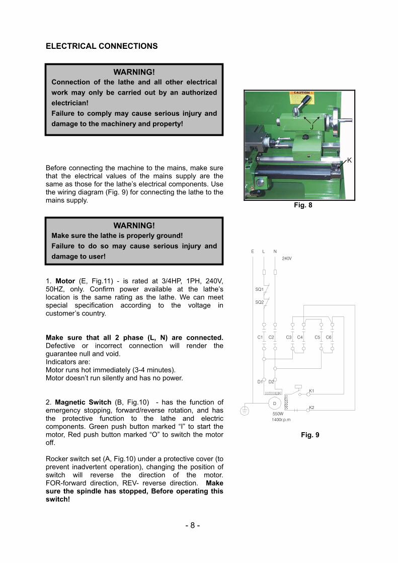
ELECTRICAL CONNECTIONS Before connecting the machine to the mains, make sure that the electrical values of the mains supply are the same as those for the lathe’s electrical components. Use the wiring diagram (Fig. 9) for connecting the lathe to the mains supply. 1. Motor (E, Fig.11) - is rated at 3/4HP, 1PH, 240V, 50HZ, only. Confirm power available at the lathe’s location is the same rating as the lathe. We can meet special specification according to the voltage in customer’s country. Make sure that all 2 phase (L, N) are connected. Defective or incorrect connection will render the guarantee null and void. Indicators are: Motor runs hot immediately (3-4 minutes). Motor doesn’t run silently and has no power. 2. Magnetic Switch (B, Fig.10) - has the function of emergency stopping, forward/reverse rotation, and has the protective function to the lathe and electric components. Green push button marked “I” to start the motor, Red push button marked “O” to switch the motor off. Rocker switch set (A, Fig.10) under a protective cover (to prevent inadvertent operation), changing the position of switch will reverse the direction of the motor. FOR-forward direction, REV- reverse direction. Make sure the spindle has stopped, Before operating this switch!
J
K
Fig. 8
K1
K2D
550W
C1 C2 C3 C4 C5 C6
SQ1
SQ2
E L N
240V
1400r.p.m
D1 D2
Fig. 9
WARNING! Connection of the lathe and all other electricalwork may only be carried out by an authorizedelectrician! Failure to comply may cause serious injury anddamage to the machinery and property!
WARNING! Make sure the lathe is properly ground! Failure to do so may cause serious injury anddamage to user!
- 9 -
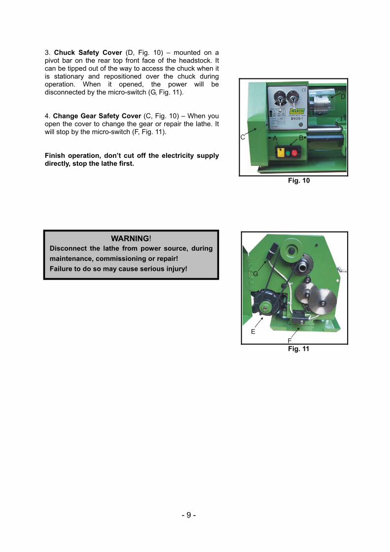
3. Chuck Safety Cover (D, Fig. 10) – mounted on a pivot bar on the rear top front face of the headstock. It can be tipped out of the way to access the chuck when it is stationary and repositioned over the chuck during operation. When it opened, the power will be disconnected by the micro-switch (G, Fig. 11). 4. Change Gear Safety Cover (C, Fig. 10) – When you open the cover to change the gear or repair the lathe. It will stop by the micro-switch (F, Fig. 11). Finish operation, don’t cut off the electricity supply directly, stop the lathe first.
A B
Fig. 10
EF
G
Fig. 11
WARNING! Disconnect the lathe from power source, duringmaintenance, commissioning or repair! Failure to do so may cause serious injury!

- 10 -
GENERAL DESCRIPTION 1 Lathe Bed - the lathe bed (A, Fig. 12) is made of cast iron with low vibration and high rigidity. The bed integrates the headstock and drive unit, for attaching the lathe saddle and leadscrew and for guiding the lathe saddle and tailstock. 2 Headstock - the headstock (B, Fig.12) houses the work spindle with bearing arrangement and the drive unit. The work spindle transmits the main movement during the turning process by gears. It also holds the workpieces by clamping device. The work spindle is driven by motor via pulleys. 3. Apron – the apron (C, Fig. 13) is mounted to the carriage. Quick travel of the apron is accomplished by means of rack and pinion which is mounted on the bed, operated by a hand wheel on the apron. Automatic longitudinal feed is accomplished via the leadscrew also. 4. Carriage – the carriage (D, Fig. 14) contains the control elements for the different feeds and supports the apron. 5. Cross Slide - the cross slide (E, Fig.14) is mounted on the carriage and moves on a dovetailed slide which can be adjusted for play by means of the gib. 6. Top Slide – the top slide (F, Fig.14) is mounted on the cross slide by T-screw which can be rotated 360 degree. The top slide moves on a dovetailed slide and has an adjusted gib, locking screw. 7. Tool Post – the tool post (G, Fig. 14) is located on a central pivot mounted on the top slide. It has four position ‘click’ locator that locates it to its major axis. It can be held at any angle by the tool post locking clamp.
A
B
Fig. 12
CFig. 13
D
E
FG
Fig. 14 .

- 11 -
8. Tailstock – the tailstock (H, Fig. 15) can be locked at any location by a bolt. It has a heavy duty quill which can be moved forward or backward. It is used for centring and drilling, supporting long shafts, turning between centres as well as turning long, thin tapers. 9. Leadscrew – the leadscrew (I, Fig. 15) under the leadscrew cover through the various gear trains available rotates at selected ratio to the spindle to enable the various threads to be cut, or to provide a feed rate for the saddle when auto feed is selected. 10. Change Gears Box – the box (J, Fig. 16) is mounted the side of headstcok. It is consists of pulleys and change gears. The rotation is transmitted through motor to spindle by pulleys and the feeds or threads are achieved with change gears and leadscrew. Open the lid case (K, Fig. 16) to make long workpieces! 11. Steady Rest – the steady rest (L, Fig. 17) serves as a support for shafts on the free tailstock end. The steady rest is mounted on the bedway and secured from below with a bolt, nut and locking plate. The sliding fingers require continuous lubrication at the contact points with the workpiece to prevent them from premature wear. 12. Follow Rest – the follow rest (M, Fig. 17) is mounted on the saddle and follows the movement of the turning tool. Only two fingers are required as the place of the third is taken by the turning tool. The follow rest is used for turning operations on long, slender workpiece. It prevents the workpiece from flexing under the pressure of the cutting tool.
H
I
Fig. 15
J
K
Fig. 16
L M
Fig. 17

- 12 -
OPERATION 1. Headstock Gear Change Levers - located on front top portion of headstock. You can select six kinds of spindle speeds by moving levers (A, B, Fig.18) right or left. 2. Apron Controls – the automatic longitudinal feed and thread cutting are achieved by engaging the lever (C, Fig. 19), push lever down to engage, pull lever up to disengage. The handwheel (D, Fig.19) is used to manually traverse the carriage. 3. Cross Slide Lever (E, Fig.19) – cross slide is moved forward and backward manually with the lever. Rotate clockwise to forward and counter-clockwise to backward. 4. Top Slide Levers (F, Fig.19) – located on the end of top slide. Rotate clockwise or counter-clockwise to move or position. Tool post clamping lever (G, Fig. 19) located on top of tool post. Rotate counter-clockwise to loosen and clockwise to tighten. Turning tapers with the top slide – loosen the two nuts (H, Fig.19) to left and right of the top slide. You can then rotate the top slide. After setting the required position, tighten the top slide. 5. Tailstock Controls – the tailstock sleeve (H, Fig. 20) is used to hold the tools. The sleeve is clamped with the clamping levers (I, Fig.20), Rotate counter-clockwise to loosen and clockwise to tighten. Rotate the handwheel (G, Fig.20) clockwise to advance the sleeve and counter-clockwise to retract it. The tailstock on the lathe bed can be clamped with the locking nut (K, Fig.20). If the tailstock has a heavy load, tighten the nut at right side on the bed. Tailstock off-set adjustment – two screws (L, Fig.20) located on the tailstock base are used to off-set the tailstock for cutting tapers. Loosening one screw while tightening the other will off-set the tailstock.
A
B
Fig. 18
CD
E
F
G
H
Fig. 19
H IG
K
L
Fig. 20
WARNING! Don’t change the speed while the lathe isrunning! Failure to comply may cause serious damage tothe lathe!

- 13 -
The locking nut must be loosened for this purpose. In order to avoid accidental extraction of the tailstock out of the lathe bed, a securing screw (M, Fig. 21) has been fitted at the end of the lathe bed.
6. Spindle Speed – the label is attached to the hedadstcok. It also shows the speed table (N, Fig. 22). As following table:
1 1402 2503 3901 6002 10803 1710
A
B
7. Feed/Thread – the label (P, Fig. 23) is attached to the change gears cover. It shows the feeds for straight turning, the change gear arrangement for longitudinal feed and for metric/imperial threads cutting. As following table:
M
Fig. 21
N
Fig. 22
P
Fig. 23
CAUTION! Check clamping of tailstock and sleeverespectively for tuning jobs between centers!
FEEDING CHANGE GEARS
IN/ A B C D
0.002 24 96 32 1200.003 24 96 44 1200.004 36 96 40 120
A
BC
D
0.006 40 63 36 120
THREAD CHANGE GEARS THREAD CHANGE GEARS
TPI
A B C D
MM
A B C D
8 63 48 120 40 0.4 63 96 68 90
9 63 48 96 36 0.5 63 96 85 90
10 63 48 96 40 0.7 49 40 68 96
11 63 48 96 44 0.8 56 40 68 96
12 63 48 96 48 1.0 63 36 68 96
14 63 48 96 56 1.25 63 96 85 36
16 63 96 96 32 1.5 63 60 85 48
18 63 96 96 36 1.7 60 49 85 48
19 63 96 96 38 2 63 60 85 36
20 63 96 96 40
24 63 96 96 48
26 63 96 96 52
28 63 96 96 56
32 63 96 96 64

- 14 -
ADJUSTMENT 1. Gib Of The Top Slide – loosen the nuts and readjust the screws (A, Fig.24) clockwise slightly. Then retighten the nuts. The top slide can be immobilised with the locking screw (B, Fig.24). 2. Gib Of Cross Slide - loosen the nuts and readjust the screws (C, Fig.25) clockwise slightly. Then retighten the nuts. The cross slide can be immobilised with the locking screw (D, Fig.25) to prevent it moving axially during process. 3. Clamping Plate Of Carriage – Two front clamp plate of carriage (E, Fig.25) are mounted on two side of carriage with four hex screws. Loosen the screws, dismount the clamping plate and regrind it. One back clamping plate are mounted on the carriage with four hex screws. Loosen the screws, dismount the clamping plate and regrind it. To prevent the carriage from moving axially during the facing process, the carriage can be immobilised with locking screw (G, Fig.26) when marking recesses, we also recommend that you immobilizes the carriage.
A
B
Fig. 24
C
DE
F
Fig. 25
G
Fig. 26
CAUTION! After a period of time some of the movingcomponents may need to be adjusted due towear.

- 15 -
DRIVING SYSTEM
550W1 2 3 4 5 6 7
40 41 42 438
9
101213
14~3111
32 33 34 36 37 38 3935Fig. 27
Description of Gears, Screws and Nuts, as following table:
Assembly
Parts No. 1 2 3 4 5 6 7 8 9 10 11 12 13
Parts Name
Specification 44T 19T 28T 52T 36T 45T 25T 44T 35T 55T 45T 18T 30T
Assembly
Parts No. 14 15 16 17 18 19 20 21 22 23 24 25 26 27 28
Parts Name
Specification 24T 32T 36T 38T 40T 44T 48T 48T 49T 56T 60T 63T 64T 68T 85T
Assembly
Parts No. 29 30 31 32 33 34 35 36 37 38 39 40 41 42 43
Parts Name Rack Nut Bolt Nut Bolt Nut Bolt Nut Bolt
Specification 90T 96T 120T 17T 51T 17T
Remark
Gear
Headstcok
Change Gear Apron
10TPI 7TPI 10TPI 10TPI
Change Gear
Gear
Gear
Cross Slide Leadscrew
Gear
Top Slide Tailstock

- 16 -
BEARING ARRANGEMENT
1 2
4
6
8
10
3
5
7
9
11
Fig. 28 Details of Bearing as following table:
Parts No. Model No. Name Specification Quantity1 104 Deep Sloot Ball Bearing 20×42×12 12 104 Deep Sloot Ball Bearing 20×42×12 13 103 Deep Sloot Ball Bearing 17×35×10 14 103 Deep Sloot Ball Bearing 17×35×10 15 46107 Agular Contact Ball Bearing 35×62×14 16 46108 Agular Contact Ball Bearing 40×68×15 17 103 Deep Sloot Ball Bearing 17×35×10 18 103 Deep Sloot Ball Bearing 17×35×10 19 103 Deep Sloot Ball Bearing 17×35×10 1
10 103 Deep Sloot Ball Bearing 17×35×10 111 8104 Thrust Ball Bearing 20×35×10 2

- 17 -
MAINTENANCE
Keep the maintenance of the machine tool during the operation to guarantee the accuracy and service life of the machine tool. 1. In order to retain the machine’s precision and functionality, it is essential to treat it with
care, keep it clean and grease and lubricate it regularly. Only through good care, you can be sure that the working quality of the machine will remain constant. Disconnect the machine plug from the mains supply whenever you carry out cleaning, maintenance or repair work!
2. Lubrication all slideways lightly before every use. The change gears and the leadscrew
must also be lightly lubricated with lithium base grease. 3. During the operation, the chips which falls onto the sliding surface should be cleaned
timely, and the inspection should be often made to prevent chips falling into the position between the machine tool saddle and lathe bed guide way. Asphalt felt should be cleaned at certain time. Do not remove the chips with your bare hands. There is a risk of cuts due to sharp-edged chips.
4. After the operation every day, eliminate all the chips and clean different part of the
machine tool and apply machine tool oil to prevent rusting.
5. In order to maintain the machining accuracy, take care of the center, the surface of the machine tool for the chuck and the guide way and avoid mechanical damage and the wear due to improper guide.
6. If the damage is found, the maintenance should be done immediately.
TROUBLE SOLUTION
Problem Possible Cause Solutiontool blunt resharpen tool tool springs clamp tool with less overhangfeed too high reduce feedradius at the tool tip too small increase radiuscentres are not aligned adjust tailstock to the centretop slide not aligned well align top slide wellfeed too high reduce feedspindle bearings is loosen readjusted the bearings
centre runs hot workpiece has expanded loosen tailstock centrecutting speed too high reduce cutting speedcross feed too high lower cross feed wedge angle too small increase wedge anglespindle bearings is loosen readjusted the bearingstool is clamped incorrectly adjust tool to the centerwrong pitch adjust the right pitchwrong diameter change workpiece to correct size
cutting edge breaks off
cut thread is wrong
workpiece becomes cone
surface of workpiece too rough
lathe is chatter
edge of tool has a short life

PARTS LISTS
BV20-1 BENCH LATHE
Warren Machine Tools Ltd Warco House, Fisher Lane, Chiddingfold,Surrey GU84TD
Tel: 01428 682929 Fax: 01428 685870 E-mail: [email protected]
Web:www.warco.co.uk

BV20-1 lathe bed assembly
1
Parts No. Description Specification QTY'
1 Motor Pulley 1
2 Motor Mounting Plate 1
3 Bed 1
4 Bracket 1
5 Sleeve 1
6 Leadscrew 1
7 Pushing Ring 1
8 Sleeve 1
9 Connection Ring 1
10 Shaft 1
11 Rack 1
12 Cover 1
13 Washer 2
14 Change Gear
15 Washer 1
16 Flange 1
21 Screw M8X20 4
22 Spring Washer 8 4
Parts No. Description Specification QTY'
23 Washer 8 4
24 Screw M6X18 4
25 Spring Washer 6 4
26 Motor 550W 1
27 Key
28 Oil Cup 6 3
29 Screw M5X16 2
30 Taper Pin 5X20 4
31 Taper Pin 6X20 2
32 Screw M5X12 4
33 Screw M5X50 4
34 Screw M5X10 2
35 Key 4X25 1
36 Screw M5X10 1
37 Switch 1
38 Screw M5X16 2
39 Taper Pin 2X5 1
40 Pin 4X16 2
41 Round Nut M18X1.5 2

Parts No. Description Specification QTY'
1 Cover 1
2 Cover Braket 1
3 Shaft 1
4 Knob 1
21 Handle 10X40 1
22 Pin 3X25 2
23 Screw M3X8 12
24 Hinge 50 2
25 Nut M3 12
2
BV20-1 lathe cover assembly

BV20-1 lathe headstock assembly
3
Parts No. Description Specification QTY'
1 Washer 1
2 Change Gear 1
3 Washer 1
4 Change Gear 1
5 Bushing 1
6 Shaft 1
7 Quadrant 1
8 Nut 1
9 Main Casting 1
10 Cover 1
11 Shift Fork 2
12 Shaft Collar 1
13 Shift Hub 1
14 Handle Base 1
15 Handle 1
16 Handle 1
17 Handle Base 1
18 Shift Hub 1
Parts No. Description Specification QTY'
19 Shaft Collar 1
20 Plate 2
31 Screw M5X16 2
32 Screw M3X8 1
33 Key 4X6 1
34 Oil Cup 6 1
35 Bolt M8X20 1
36 Washer 8 1
37 Screw M5X15 1
38 Screw M5X15 4
39 Screw M5X6 1
40 Screw M5X12 2
41 Spring 2
42 Steel Ball 5 2
43 Screw M5X10 6
44 Screw M5X10 2
45 Oil Window M16X1.5 1

4
BV20-1 lathe apron assembly
Parts No. Description Specification QTY'
1 Gear Shaft 1
2 Bracket
3 Sleeve 1
4 Hulf Nut 2
5 Guide 1
6 Half Nut Cam 2
7 Gear 1
8 Shaft 1
9 Sleeve 1
10 Leadscrew Cover 1
11 Plug 1
12 Main Casting 2
13 Wheel Flange 1
14 Sleeve 1
15 Scale Ring 2
16 Handwheel 1
17 Bolt 1
18 Adjust Screw 1
19 Handle 1
Parts No. Description Specification QTY'
20 Handle Base 1
21 Handle 1
31 Key 5X10 1
32 Oil Cup 6 1
33 Screw M5X18 4
34 Screw M8X20 3
35 Pin 6X25 2
36 CClip 16 1
37 Pin 8X25 1
38 Key 4X28 1
39 Screw M4X6 2
40 Screw M5X22 1
41 Screw M5X15 1
42 Screw 5X25 1
43 Screw M5X12 3
44 Nut M10 1
45 Ball 6 1
46 Spring 0.8X6X25 1
47 Nut M12X1.25 1
48 Screw M8X10 1
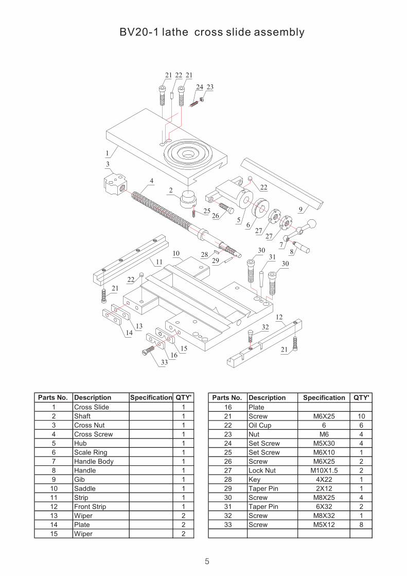
BV20-1 lathe cross slide assembly
5
Parts No. Description Specification QTY'
1 Cross Slide 1
2 Shaft 1
3 Cross Nut 1
4 Cross Screw 1
5 Hub 1
6 Scale Ring 1
7 Handle Body 1
8 Handle 1
9 Gib 1
10 Saddle 1
11 Strip 1
12 Front Strip 1
13 Wiper 2
14 Plate 2
15 Wiper 2
Parts No. Description Specification QTY'
16 Plate
21 Screw M6X25 10
22 Oil Cup 6 6
23 Nut M6 4
24 Set Screw M5X30 4
25 Set Screw M6X10 1
26 Screw M6X25 2
27 Lock Nut M10X1.5 2
28 Key 4X22 1
29 Taper Pin 2X12 1
30 Screw M8X25 4
31 Taper Pin 6X32 2
32 Screw M8X32 1
33 Screw M5X12 8

BV20-1 lathe top slide assembly
Parts No. Description Specification QTY'
1 Knob 1
2 Handle Shaft 1
3 Hnadle Base 1
4 Washer 1
5 Post Base 1
6 Stop 1
7 Sleeve 1
8 Compound Slide 1
9 Gib 1
10 Nut 1
11 Screw 1
12 Swivel Slide 1
13 Compound Screw 1
14 Frame 1
15 Scale Plate 1
16 Scale Ring 1
17 Handle Body 1
Parts No. Description Specification QTY'
19 Handle 2
20 Scale Label 1
31 Spring 0.8X5X8 1
32 Set Screw M4X10 1
33 Set Screw M5X6 2
34 Nut M5 1
35 Set Screw M5X18 1
36 TBolt M6X20 2
37 Nut M6 2
38 Allen Screw M5X20 1
39 Set Screw 6 2
40 Screw M5X20 2
41 Key 1
42 Lock Nut M10X1 2
43 Taper pin 3X16 1
44 Rivet 2X6 2
45 Screw 8
6

BV20-1 lathe tailstock assembly
Parts No. Description Specification QTY'
1 Bolt 1
2 Handle 1
3 Handwheel 1
4 Scale Ring 1
5 Flange 1
6 Sleeve 1
7 Screw 1
8 Nut 1
9 Quill 1
10 Body 1
11 Handle 1
12 Handle Base 1
13 Nut 1
14 Bracket 1
Parts No. Description Specification QTY'
15 Base 1
16 Screw 1
17 Clamp Plate 1
20 Nut M8 1
21 Screw M4X10 4
22 Key 4X6 1
23 Screw M5X10 1
24 Screw M6X8 1
25 Oil Cup 6 2
26 Taper Pin 4X6 1
27 Screw M6X18 1
28 TBolt M12X90 1
29 Washer 12 1
30 Nut M12 1
7