mini telemaster - hobby express telemaster hobby express 5614 franklin pike circle brentwood tn...
TRANSCRIPT

MINI TELEMASTER
Hobby Express 5614 Franklin Pike Circle
Brentwood TN 37027 USAPhone 866-512-1444
MADE IN THE USA
ASSEMBLY MANUAL


Terminology used in this manual. With the precision of laser cut parts and notch and tab construction, the assembly and gluing sequence becomes very important. If components are glued in place to soon, they will not allow enough move-ment to install other components. When instructed to install a part, do only that. You will be instructed to glue it when it is no longer required to be moveable.
Test Fit:Test fit and install but do not glue.
Install and glue:Permanently install the part.
Locate and prepare:Find the parts requested, you can locate them faster using the parts locator pages at the back of this manual. The parts locator will direct you to the correct sheet number as well as describe the part for easier identification. Most of the parts are supplied still in the sheet. These sheets are called the carrier sheet and the parts are held in the carrier sheet by small breaks in the cutting line. These are called retainer breaks and in most cases the parts can be extricated by simply flexing the carrier sheet and the retainer breaks will release the parts. In harder materials it may be necessary to use your hobby knife to sever the retainer breaks to remove the parts. After removing the parts, a small nub may remain where the retainer break was, this must be removed with a light swipe of sandpaper so it will not interfere with the parts fit.
Adhesives:There are four primary types of adhesives recommended for constructing your model. They are Cyano-Acrilate (referred to as CA) in all viscosities, Aliphatic Resin Glue (carpenters glue), Polyurethane glue referred to as PU and Epoxy. CA is the primary adhesive to use however there are times when it is not the best choice. They are:1. When you need more time to carefully position a part than a fast setting adhesive will allow.
2. When attaching plastic such as a windshield (Use Pacer formula 560 here).
3. When gluing laser cut aircraft grade plywood’s. The microwave set adhesives used in aircraft grade plywood does not ablate well under a laser beam. As a result it burns the wood fibers near by leaving a charred edge. Fast setting CA adhesives do not allow time for the adhesive to penetrate this layer of char and bond to the wood fiber underneath. Use a slower setting adhesive such as Aliphatic Resin for maximum strength use Epoxy on aircraft grade ply parts. Lite Ply’s do not use this type of adhesive and do not suffer from this problem.
To apply thin CA we recommend the Dave Brown pipets available from Hobby Lobby. Be sure to stretch the end (pull it with a pair of pliers) to a thin applicator tip, as they are not supplied in this configura-tion.
1

2
Stabilizer Assemblyc 1 Lay the stabilizer plans on the bench and cov-
er it with waxed paper. Carefully align a 1/8” x 1/4” x 36” balsa stick with the leading edge and pin to the plans with push pins. Trim the ends to match the plans.
c 2 Install and glue the tip pieces (WT) to the leading edge and secure with pushpins.
c 3 Install and glue the center section ST-A to the leading edge and secure with pushpins.
c 4 Cut a piece of 1/8” x 1/4” balsa to fit the trail-ing edge doubler and glue in place to ST-A.
c 5 Cut and glue two pieces of 1/8” x ¼” balsa to match the trailing edge. Glue these to the trailing edge doubler and the stabilizer tips (ST). Note that you will leave a 1/8” gap at the center to allow for the vertical fin post.
c 6 Install and glue the six 1/8” x 1/4” balsa ribs.
c 7 Install and glue the 1/8” sq. balsa angle brac-es.
ABOVE: The leading edge and trailing edge doubler have been attached to ST-A and then the trailing edge has been attached to the trailing edge doubler. Note that gap for the vertical fin post.
Assembling the registration pins.
We will be using two types of pins; registra-tion pins and push pins. Registration pins are assembled from two 1/4” ply parts, one 1/16” ply part and two 8d nails. Push pins will be used to temporarily secure parts to the build-ing board.Locate the two 1/4” ply parts labeled PB and one 1/8” ply part labeled PB. Refer to the graphic at the right and assemble using Ep-oxy or aliphatic resin glue. After installing the nail, use Epoxy to secure the nail from the bot-tom. Note that the assembly must sit flat on the bench when completed.
BEFORE YOU BEGIN1/4” Ply
1/8” Ply
Completed Assembly
8d Nail

c 3 Bevel the leading edge to allow for hinge movement.
c 4 Before covering, remove the plug from the appropriate notch (left or right) for the eleva-tor horn. Install and glue the horn only after covering.
ABOVE: The elevator assembly is ready for covering. The control horn has been temporarily installed to show the correct position. Note the bevel on the leading edge, this will allow for hinge move-ment. This model will use a film or tape hinge.
This concludes the assembly of the eleva-tor.
3
c 8 Remove the assembly from the plans and sand flat to remove any irregularities.
This concludes the assembly of the stabi-lizer.
Elevator assemblyc 1 Align the two elevator halves with the plans and pin in place. Cut a piece of 1/8” x 1/4” basswood to fit in
the joiner gap and glue in place.c 2 Sand this assembly flat to remove any irregularities.
RIGHT: The stabilizer tip is attached to the leading and trailing edges.

Rudder & Tail wheel assembly
c 1 Locate the 4” length of .047” music wire, re-fer to the drawing on the plans as a guide to bend it to the shape of the tail wheel axle.
c 2 Sand the rudder (RU) smooth and slightly round off the edges. Plane or sand a slight chamfer on both sides at the leading edge.
c 3 Drill a 1/16” hole deep enough to accept the tail wheel axle. Cut a slight groove in the trail-ing edge from this hole to the bottom of the rudder to recess the tail wheel axle wire.
c 4 Do not permanently assemble these compo-nents yet; it is best to do this after covering.
c 5 Locate the 1/8” foam tire and the two 1/16” ply discs (TW). Harden the axle holes in the ply discs by applying thin CA. Use the axle to align these components and glue them to-gether with thick CA.
BELOW: The completed rudder assembly with the tail wheel axle and rudder horn temporarily installed. These components will be permanently installed after the rudder is covered.
This concludes assembly of the rudder and tail wheel assemblies.
4
c 1
Vertical fin assembly
Cut a 6” length of 1/8” x 1/4” Basswood for the vertical fin trailing edge. Pin it in place over the plans. Note that you will not be able to pin through the basswood easily, hold it in place by bracketing it with pushpins on either side.
c 2 Glue VF-A and VF-B to the trailing edge and then pin them in place.
c 3 Glue the dorsal fin (DF) in place on the lead-ing edge.
c 4 Cut and install the 1/8” x 1/4” rib.
c 5 Install and glue the 1/8” sq. bracing.
This concludes the vertical fin assembly
5
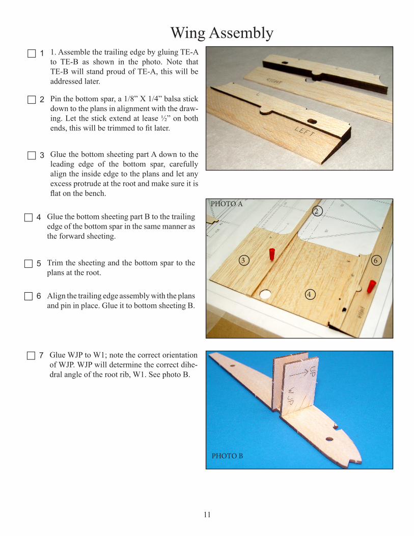
c 3 Place the plans on the workbench and cover the fuselage side view with waxed paper. Place one of the fuselage sides in register to the plans and pin in place with pushpins.
c 4 Glue one 1/8” x 1/4” x 36” balsa stringer into the notch provided at the top of the fuselage side assembly. Trim this stringer off in line with the aft edge of the vertical fin trailing edge.
c 5 Repeat step 4 with another stringer at the bot-tom of the fuselage and trim it off at the aft edge of the vertical fin trailing edge.
c 6 Carefully align F8 to the plans at the aft end. Pin in place with pushpins. Glue the top and bottom corner stringer to F8.
ABOVE: The top fuselage corner stringer has been glued to the fuselage side assembly and the bottom corner stringer is ready to install.
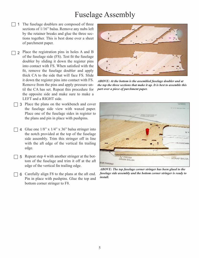
Fuselage Assemblyc 1 The fuselage doublers are composed of three
sections of 1/16” balsa. Remove any nubs left by the retainer breaks and glue the three sec-tions together. This is best done over a sheet of parchment paper.
c 2 Place the registration pins in holes A and B of the fuselage side (FS). Test fit the fuselage doubler by sliding it down the register pins into contact with FS. When satisfied with the fit, remove the fuselage doubler and apply thick CA to the side that will face FS. Slide it down the register pins into contact with FS. Remove from the pins and apply pressure un-til the CA has set. Repeat this procedure for the opposite side and make sure to make a LEFT and a RIGHT side.
ABOVE: At the bottom is the assembled fuselage doubler and at the top the three sections that make it up. It is best to assemble this part over a piece of parchment paper.

6
c 15 Install and glue F3, note that F3 and WNB should be installed the same time. Use F3 to align WNB and glue WNB to the fuselage side, then install F3.
c 16 Install and glue FST to the fuselage side and F3.
c 17 Next you will install the left fuselage side to the right fuselage side assembly. To allow you time to get all the tabs lined up, use a slow setting adhesive such as aliphatic resin glue. Apply glue to all the interfacing surfaces and install the left fuselage side. Install the remaining WNB at the same time. Place this assembly flat on the bench and place a weight on it until the glue has cured.
c 18 Place the fuselage assembly over the top view of the plans. Now carefully align the forward fuselage sec-tion with the plans and weight or pin it firmly in place.
c 7 Place another layer of waxed paper over this fuselages assembly and assemble the oppo-site side directly over it to insure that the two sides are exactly the same. Remember you are making a LEFT and a RIGHT.
c 8 Use pinning holes C and D and the registra-tion pins to install and glue the gear braces (GB) to the inside of each fuselage side.
c 9 Install a #6-32 blind nut into each wing nut bracket (WNB). Make a LEFT and a RIGHT.
ABOVE: The landing gear brace (GM) is installed using the regis-tration pins. Note that the slots in the two gear braces are offset for each other to align with the cris cross gear legs.
c 10 Locate and prepare the following parts, F1, FF, F2, FHM, F3, and FST. These will all be installed and glued to the right fuselage side first and the left side will be added to this as-sembly.
ABOVE: Installation of internal structures underway. Make sure all tabs are bottomed in there respective slots to assuer an accurate structure.
c 11 Use thick CA to install and glue F1 into the notches provided in the fuselage side. Use the square provided to insure that it is at 90º to the fuselage side.
c 12 Install and glue F2 in the same manner. Note that F2 does not require any glue in the area of the landing gear slot in GB
c 13 Install and glue FHM, note that the side with the half circle cut out of it will face F2.
Install and glue FF to the fuselage side and F2. Note that FF must be placed through F2 with the slots aligned with F2. It’s best to test fit this before applying glue.
c 14

c 23
7
Install and glue a 1/8” x 1/4” balsa stringer in the notches provided in F3, F4, F5 and F6, top and bottom.
c 24 The landing gear mount consists of GM-A and GM-B. Place GM-B in the notches pro-vided at the bottom of the fuselage. Note that the holes on either side are offset from each other. Orient GM-B so the holes line up with the slots in GB. Then glue GM-A and GM-B together in this orientation. Use the registra-tion pins to align the parts.
c 25 Glue the GM assembly to the fuselage, note that GM-A should be facing outward.
ABOVE: One landing gear leg is temporarily installed to check the correct orientation of GM-B. The holes in GM-B must line up with the offset slots in GB. Once this has been determined, the parts are removed and GM-A and GM-B are assembled in this orientation.
BELOW: The completed landing gear installation. This design makes the gear easily removable for stor-age and maintenance.
c 19 Place F9 between the tail section and careful-ly align it with the plans. Pull the tail section into contact with F9 and when satisfied that both sides are even, glue F9 to the fuselage sides. F9 should be flush with the top of the corner stringers. Turn the fuselage assem-bly over and install F11 in the same manner. When positioning F11, leave 1/4” gap at the tail end for the vertical fin tail post.
c 20 With the fuselage assembly over the top view on the plans, mark the location of F4, F5 and F6 on the corner stringers.
c 21 Install and glue F4, F5 and F6. Start with F4 and work back to F6.
c 22 Cut and install the 1/8” sq. balsa angle bracing on the inside of the fuselage stringers. Hint, after trimming one stick to size, use it as a pattern to cut the stick for the opposite side.
ABOVE: Note that F11 should leave a 1/4” gap at the tail end. You will need to open up an equivalent gap in F11 to allow for the vertical fin tail post to insert.

c 27 Install and glue the nose doublers (ND).
8
c 26 Install and glue F10 to the fuselage sides and F3, this will support the bottom sheeting where it tapers to the stringer. F10 should be flush to the bottom stringers.
BELOW: The gear mount assembly is glued to the fuselage after determining the correct orientation to align with the slots in the gear braces. The gear is then retained with plywood gear straps and four #2 x 1/4” sheet metal screws.

9
c 31 Glue hatch hooks (HA-B) to the bottom of the hatch (HA). Note that these can only be in-stalled one way.
c 32 Glue the remaining magnet into the hole pro-vided in the hatch (HA). Make sure the polar-ity is correct to attract the magnet in FHM. This magnet must be flush to the bottom of the hatch.
c 33 Install the hatch onto the fuselage. Install and glue the ¾” triangle stock to the hatch. You will need to relieve some of the material where the magnet stands proud of the hatch to get a snug fit.
ABOVE: The completed hatch assembly with the magnet installed, the 3/4” triangle stock and the hatch hooks (HA-B) installed.
c 28 Install and glue a 2-1/2” long piece of ¼” triangle stock into the notch provided at the windshield location.
c 29 Install and glue the windshield (WS) in posi-tion. Note that WS will but up against the tri-angle stock. Sand WS flush with the triangle stock if necessary.
c 30 Install and glue one of the two magnets into the hole provided in FHM, note that magnet must be flush with FHM on the top.

10
c 34 Glue the shim stock from sheet #5 to the flanges on GM-B to bring them up flush to the fuselage sides.
c 35 Sheet the bottom of the fuselage with 1/16” balsa cross grain from F1 to the GM and from GM back to F3.
BELOW: The fuselage bottom sheeting has been installed and sanded to complete the basic fuselage assembly. Note that the sheet-ing is sanded to a taper at F10 and ends up flush with the aft edge of F10.
These concludes the fuselage assembly, fill any voids with wood filler and sand all sur-faces smooth in preparation for covering. The stabilizer, vertical fin, rudder and el-evator are all covered before attaching to the fuselage.
11
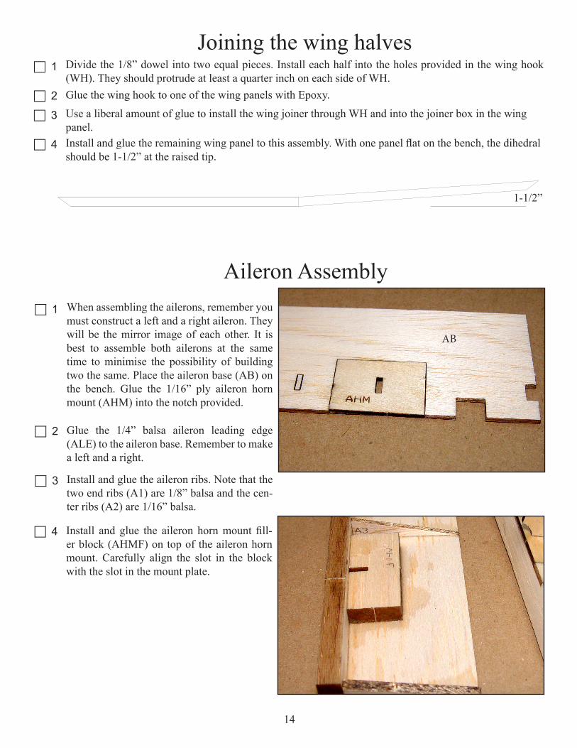
c 4 Glue the bottom sheeting part B to the trailing edge of the bottom spar in the same manner as the forward sheeting.
c 5 Trim the sheeting and the bottom spar to the plans at the root.
c 6 Align the trailing edge assembly with the plans and pin in place. Glue it to bottom sheeting B.
c 7 Glue WJP to W1; note the correct orientation of WJP. WJP will determine the correct dihe-dral angle of the root rib, W1. See photo B.
Wing Assemblyc 1 1. Assemble the trailing edge by gluing TE-A
to TE-B as shown in the photo. Note that TE-B will stand proud of TE-A, this will be addressed later.
c 2 Pin the bottom spar, a 1/8” X 1/4” balsa stick down to the plans in alignment with the draw-ing. Let the stick extend at lease ½” on both ends, this will be trimmed to fit later.
c 3 Glue the bottom sheeting part A down to the leading edge of the bottom spar, carefully align the inside edge to the plans and let any excess protrude at the root and make sure it is flat on the bench.
2
3
4
6
PHOTO A
PHOTO B

12
Install but do not glue ribs W2 through W7 onto the bottom spar and the notches in the trailing edge. You may notice that the plans do not fit the parts, do not be concerned. The paper these plans are printed on may change size depending on temperature and humidity. The parts are correct so use the plans to align the parts only.
c 11
c 10
c 9
Glue only W7 to the trailing edge (TE-A). In-stall and glue the gusset (GU1) between W7 and TE-A. See photo D.
11. Install but do not glue the aileron bay trail-ing edge (ABTE) into W7.
c 12 12. Lay the wing servo mounting plate (WSM) in position between ribs W7 and W8.
c 13 Install but do not glue the remaining ribs W8, W9 and W10.
c 14 Install but do not glue the leading edge. Adjust each rib to fit into the notch provided in the leading edge. Note that the notched side of the leading edge should be down. Sight down the leading edge and note that all ribs look exactly the same.
c 15 IMPORTANT; in this step you will glue all the parts at the same time. It is important that you make sure that each component is bottomed in the appropriate slot as well as making sure all ribs are flat on the building board. When all ribs are properly seated in their respective notches in the leading edge and trail-ing edge, glue them to the leading edge, trailing edge, bottom spar and the ABTE. Also glue W2 and W3 to the bottom sheeting however do not glue the forward 1” of these two ribs. This will be done later after trimming the sheeting to fit the leading edge. Also center the servo mount evenly between W7 and W8 and glue it to both ribs and the bottom spar.
c 8 Carefully align W1 with the root end of the plans and glue to bottom sheeting A, B and the bottom spar. Make sure WJP is flat on the building board. Do not glue the bottom for-ward 1” of W1 to A, this will be glued to con-form to the bottom of the rib after removal from the plans. See photo C.
PHOTO C
PHOTO D
GU1

13
c 18
c 17
c 16 16. Install and glue a 1/8” sq. balsa in the notches provided in the leading edge of each rib. This will serve to stiffen the top sheeting.
PHOTO E
Glue a piece of 1/8” square scrap to each side of the servo mount to help secure it to W7 and W8. See photo E.Trim the bottom spar flush with W10 at the tip.
c 19 Install and glue the 1/8” x ¼” top spar. Trim the top spar flush with W1 and W10
c 20 Glue sheer webs in each bay between the ribs as indicated on the plans.
c 21 Install and glue the geodetic ribs G1 through G6 in each bay. Note that G1 has some material removed to accommodate the sheeting. Sand a slight bevel on each end of these ribs to increase glue land and improve the fit. These ribs may have to be bowed slightly to install but should be straight after they are installed.
c 22 Install and glue the wing tip (WT) to rib W10. Use the gusset (WTGU) at the location of the spar to set the correct angle. Glue a ½” piece of ½” triangle stock filler at the trailing edge and a ¾” piece of ½” triangle stock at the leading edge.
c 24 Trim the bottom center section sheeting (A) to butt fit to the leading edge and then glue it to W1, W2, W3 and the leading edge.
c 25 Shape the leading edge to contour with the ribs in preparation for installing the top leading edge sheeting. Trim and sand W10 and the wing tip to match. Note that W10 is offset 1/32” aft of the spar to accommodate the 1/32” tip sheeting. W1, W2 and W3 are also offset in this same manner so that after sheeting they will be flush with the rest of the ribs.
c 26 Glue the top aft center section sheeting (D) on. Note that this sheeting should slightly overlap the top spar.
Run a bead of thick CA down the top spar and install the top leading edge sheeting. Glue it only to the top spar at this time. Use a straight edge to press the sheeting into contact with the top spar.
c 28
c 29 Turn the assembly over. Apply enough me-dium CA to the front of W2 until it runs down the top of the rib as far back as the spar and then hold the top sheeting into contact with W2 until it cures. Apply thin CA to the lead-ing edge and the top sheeting. Moving down the wing from the root, glue the top sheeting to each rib and the leading edge.
c 30 Remove the dash cut material in W1 between the top and bottom spars.
This completes assembly of one wing panel, repeat steps 1 through 30 for the remaining wing panel.
c 23 Remove the wing assembly from the plans.
c 27 Plane or sand TE-B to contour with the trailing edge (TE-A) and the center sheeting.
Joining the wing halves
c 4
c 3
c 2
c 1 Divide the 1/8” dowel into two equal pieces. Install each half into the holes provided in the wing hook (WH). They should protrude at least a quarter inch on each side of WH.Glue the wing hook to one of the wing panels with Epoxy.Use a liberal amount of glue to install the wing joiner through WH and into the joiner box in the wing panel.Install and glue the remaining wing panel to this assembly. With one panel flat on the bench, the dihedral should be 1-1/2” at the raised tip.
1-1/2”
c 1
Aileron AssemblyWhen assembling the ailerons, remember you must construct a left and a right aileron. They will be the mirror image of each other. It is best to assemble both ailerons at the same time to minimise the possibility of building two the same. Place the aileron base (AB) on the bench. Glue the 1/16” ply aileron horn mount (AHM) into the notch provided.
c 2 Glue the 1/4” balsa aileron leading edge (ALE) to the aileron base. Remember to make a left and a right.
c 3 Install and glue the aileron ribs. Note that the two end ribs (A1) are 1/8” balsa and the cen-ter ribs (A2) are 1/16” balsa.
AB
c 4 Install and glue the aileron horn mount fill-er block (AHMF) on top of the aileron horn mount. Carefully align the slot in the block with the slot in the mount plate.
14

c 6 Install and glue the 3/8” triangle stock aileron tips, then trim them to contour with the ribs.
This concludes the aileron assembly. The ai-leron horns are installed permanently after the ailerons have been covered. The ailerons are attached wit tape hinges or you may prefer making a hinge from your favorite covering.
IMPORTANT:When setting up your ailerons, use differential throw for best results. Use 1” of up and 1/2” of down.
c 5 Plane or sand the aileron leading edge to con-tour with the ribs. Note that this will include some material from the horn block.
ABOVE: Before and after contouring the leading edge and horn block to the ribs.
LEFT RIGHT
15
Joining the wing halves
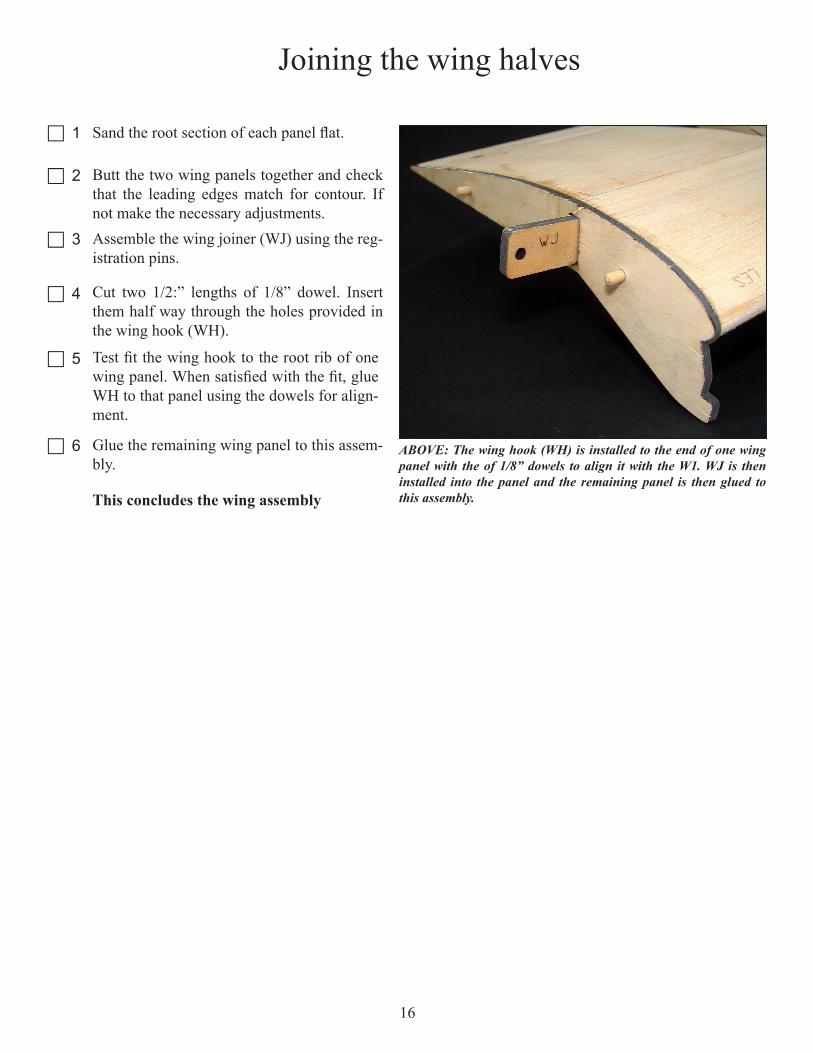
c 1 Sand the root section of each panel flat.
c 2 Butt the two wing panels together and check that the leading edges match for contour. If not make the necessary adjustments.
c 3 Assemble the wing joiner (WJ) using the reg-istration pins.
c 4 Cut two 1/2:” lengths of 1/8” dowel. Insert them half way through the holes provided in the wing hook (WH).
c 5 Test fit the wing hook to the root rib of one wing panel. When satisfied with the fit, glue WH to that panel using the dowels for align-ment.
c 6 Glue the remaining wing panel to this assem-bly.
This concludes the wing assembly
ABOVE: The wing hook (WH) is installed to the end of one wing panel with the of 1/8” dowels to align it with the W1. WJ is then installed into the panel and the remaining panel is then glued to this assembly.
16

17
Part# Qty Sheet# Size MaterialA 2 11 1/32” X 3” X 36” BALSA Wing sheeting part AA2 4 8 1/16” X 6” X 36” BALSA Aileron RibA4 4 3 1/8” X 3” X 36” BALSA Aileron end ribsAB 1 7 1/16” X 6” X 36” BALSA Aileron baseABTE 2 12 3/16” X 1-1/2” X 9” BALSA Aileron bay trailing edgeACW 1 5 1/16” X 3” X 24” AC PLY Wing bolt anticrush platesAHMF 2 1 1/4” x 1-1/2” x 36” BALSA Aileron horn mounting fillerAHM 2 5 1/16” X 3” X 24” AC PLY Aileron horn mountAIL 2 5 1/16” X 3” X 24” AC PLY Aileron hornALE 2 1 1/4” x 1-1/2” x 36” BALSA Aileron leading edgeB 2 10 1/32” X 4” X 36” BALSA Wing bottom sheeting, rootDF 1 3 1/8” X 3” X 36” BALSA Dorsal finD 2 9 1/32” X 4” X 36” BALSA Wing top sheeting, rootEV 2 3 1/8” X 3” X 36” BALSA ElevatorEH 1 5 1/16” X 3” X 24” AC PLY Elevator hornF1 1 2 1/8” X 3” X 10” AC PLY Fuselage former #1F10 1 7 1/16” X 6” X 36” BALSA Fuselage braceF11 1 14 3/32” X 3 X 5” BALSA Fuselage tail sheetingF12 1 14 3/32” X 3 X 5” BALSA Wing bolt braceF2 1 13 3/32” X 3” X 8” AC PLY Fuselage former #2F3 1 5 1/16” X 3” X 24” AC PLY Fuselage former #3F4 1 5 1/16” X 3” X 24” AC PLY Fuselage former #4F5 1 5 1/16” X 3” X 24” AC PLY Fuselage former #5F6 1 5 1/16” X 3” X 24” AC PLY Fuselage former #6F8 2 3 1/8” X 3” X 36” BALSA Fuselage side, tailF9 1 3 1/8” X 3” X 36” BALSA Fuselage side, tailFD 5 6 1/16” X 6” X 36” BALSA Fuselage doubler sectionsFD 1 7 1/16” X 6” X 36” BALSA Fuselage doubler sectionsFF 1 5 1/16” X 3” X 24” AC PLY Fuselage floorFHM 1 4 1/8” X 3” X 8” LPLY Fuselage hatch mountFST 1 4 1/8” X 3” X 8” LPLY Fuselage servo trayFS 1 6 1/16” X 6” X 36” BALSA Fuselage sideFS 1 7 1/16” X 6” X 36” BALSA Fuselage sideG2 4 6 1/16” X 6” X 36” BALSA Geodetic rib #2G2 2 7 1/16” X 6” X 36” BALSA Geodetic rib #4G4 2 7 1/16” X 6” X 36” BALSA Geodetic rib #5G5 4 7 1/16” X 6” X 36” BALSA Geodetic rib #5GB 2 4 1/8” X 3” X 8” LPLY Gear baseGM-A 1 13 3/32” X 3” X 8” AC PLY Gear mount part AGM-B 1 13 3/32” X 3” X 8” AC PLY Gear mount part BGU1 2 3 1/8” X 3” X 36” BALSA Gusset 1GU2 2 3 1/8” X 3” X 36” BALSA Gusset 2

18
Part# Qty Sheet# Size MaterialHA-A 1 5 1/16” X 3” X 24” AC PLY Fuselage hatch part AHA-B 1 13 3/32” X 3” X 8” AC PLY Fuselage hatch part BLE 2 1 1/4” x 1-1/2” x 36” BALSA Wing leading edgeLE TEMP 1 4 1/8” X 3” X 8” LPLY Leading edge templateLES 1 9 1/32” X 4” X 36” BALSA Wing leading edge sheetingLES 1 10 1/32” X 4” X 36” BALSA Wing leading edge sheetingLG STRAPS 2 5 1/16” X 3” X 24” AC PLY Wing leading edge sheetingLGF 2 14 3/32” X 3 X 5” BALSA Landing gear faringND 2 3 1/8” X 3” X 36” BALSA Nose doublerRU 1 3 1/8” X 3” X 36” BALSA RudderRH 1 5 1/16” X 3” X 24” AC PLY Rudder hornST 2 3 1/8” X 3” X 36” BALSA Stabilizer tipST-A 1 3 1/8” X 3” X 36” BALSA Stabilizer Part ASW 16 11 1/32” X 3” X 36” BALSA Wing sheer websTS 1 9 1/32” X 4” X 36” BALSA Wing tip sheetingTS 1 10 1/32” X 4” X 36” BALSA Wing tip sheetingTW 2 5 1/16” X 3” X 24” AC PLY Tail wheel discsVF-A 1 3 1/8” X 3” X 36” BALSA Vertical fin part AVF-B 1 3 1/8” X 3” X 36” BALSA Vertical fin part BW1 2 8 1/16” X 6” X 36” BALSA Wing rib #1W10 2 8 1/16” X 6” X 36” BALSA Wing rib #10W2 2 8 1/16” X 6” X 36” BALSA Wing rib #2W3 2 8 1/16” X 6” X 36” BALSA Wing rib #3W4 2 8 1/16” X 6” X 36” BALSA Wing rib #4W5 2 8 1/16” X 6” X 36” BALSA Wing rib #5W6 2 8 1/16” X 6” X 36” BALSA Wing rib #6W7 2 8 1/16” X 6” X 36” BALSA Wing rib #7W8 2 8 1/16” X 6” X 36” BALSA Wing rib #8W9 2 8 1/16” X 6” X 36” BALSA Wing rib #9WH 1 2 1/8” X 3” X 10” AC PLY Wing hookWJ 1 Loose 1/4” LPLY Wing joinerWJP 4 8 1/16” X 6” X 36” BALSA Wing joiner pocketWNB 2 4 1/8” X 3” X 8” LPLY Wing nut bracketWS 1 3 1/8” X 3” X 36” BALSA Fuselage wind shieldWSM 2 5 1/16” X 3” X 24” AC PLY Wing servo mountWTGU 2 1 1/4” x 1-1/2” x 36” BALSA Wing gussetWTGU 2 7 1/16” X 6” X 36” BALSA Wing gusset

19

20
Mini Telemster TEL1250 Inventort CheckoffLaser cut materialsCheck Off Sheet# Size Material
1 1/4” X 1” X 36” BALSA2 1/8” X 3” X 10” PLYWOOD3 1/8” X 3” X 36” BALSA4 1/8” X 3” X 7” LITE PLYWOOD5 1/16” X 3” X 20” AC PLY6 1/16” X 6” X 36” BALSA7 1/16” X 6” X 36” BALSA8 1/16” X 4” X 36” BALSA9 1/32” X 4” X 36” BALSA10 1/32” X 4” X 36” BALSA11 1/32” X 3” X 36” BALSA12 3/16” x 1-1/2” x 9” BALSA13 3/32” X 3” X 8” PLYWOOD14 3/32” X 4” X 4” BALSA
Additional building materialCheck Off Item Qty. Size Material
Sheet 1 1/32” x 4” x 18” Hard BalsaTriangle stock 1 3/4” x 2-1/2” BalsaTriangle stock 1 1/4” x 5” BalsaDowel 1 1/8” x 2” Hd. Wd.Stick 10 1/8” x 1/4” x 36” BalsaStick 4 1/8” x 1/8” x 36” BalsaStick 1 1/8” x 1/4” x 10” Basswood
Hardware ItemsCheck Off Item Qty. Size Material
Formed Wire 2 3/32” x 14” M.W. FabricateWire 2 .047” x 36” Music WireNut 2 #6-32 Blind NutsBolt 2 #6-32 X 1-7/8” NylonBolt 4 #4-40 X 3/8” PlatedNut 4 #4-40 NylockScrew 4 #1 X 1/4” Sheet Metal
ScrewSquare 1 1/4” Lite PlyMagnet 2 1/4” x 1/8” MolybdeniteRegisteration Pins 2 8d x 2-1/2” Modified NailRegisteration Pin Blocks
2 1/2” x 1/1-2” x 3” MDF Block
Tail Wheel 1 1/8” x 5/8” Foam
21
EZ-Link 4 Mini Du-BroEZ-Connector 4 Mini Du-BroWire 1 .047” MW Z-BendsWing Joiner 1 1/4” Lite PlyWheel 2 2” Dave BrownWheel Collar 2 3/32” Du-Bro

Hobby Express 5614 Franklin Pike Circle
Brentwood TN 37027 USAPhone 866-512-1444