mini workshop manual - 5th edition - eng - us cars - la ... · workshop manual werkplaatshandboek...
TRANSCRIPT

Workshop Manual
Werkplaatshandboek
Manuel D’Ate l ier
Werkstatthandbuch
Manuale D’Off ic ina
Manual De Tal ler
Manual de Of ic ina


AMENDMENT INSTRUCTION SHEET
MINI WORKSHOP MANUALPublication Number RCL 0193ENG - 2nd Edition
Amendment Number: XN-001/97ENG Date: 12/96
To ensure that this manual is kept up to date and that a record of amendments to this manual is available, anAmendment Instruction Sheet will be issued with each set of revised pages.
• The Title page of the Manual is re-issued, and the Part No. has been raised to the next edition. Except for theContents pages, all revised and new pages have the issue date at the foot of each page, together with anindication of whether the pages are revised or new.
• This Amendment Instruction Sheet must be inserted at the front of the manual to indicate that the amendmenthas been incorporated. Do not discard previous Amendment Instruction sheets.
• Your manual is only complete to this issue providing all prior Amendments are included.
• The filing instructions give section and page numbers affected. Additional pages or complete new sections maybe issued, insert the pages as instructed.
FILING INSTRUCTIONS
Section Discard ExistingPages
Insert New Pages Reason for Amendment
Introduction Title Page Title Page Introduction of new sections. Part numberraised to next edition.
Information Contents Page Contents Page Corrections to existing information andaddition of new torque figures.
General data,1 General data,1Torque wrenchsettings, 1&3
Torque wrenchsettings, 1-5
Engine Contents Page Contents Page Corrections to existing information andaddition of new repair procedures.
Repairs, 33-37 Repairs, 33-41
Emission Control Description andoperation, 1
Description andoperation, 1
Corrections to existing information.
Repairs, 1 Repairs, 1
Engine ManagementSystem - MEMS
Contents Page Contents Page Corrections to existing information.
Description andoperation, 1-11
Description andoperation, 1-11
Fuel Delivery System Contents Page Contents Page Corrections to existing information andintroduction of Adjustments section.
- AdjustmentsRepairs, 1 Repairs, 1
Cooling System Repairs, 3 Repairs, 3 Corrections to existing information.
Manifold & ExhaustSystems
Description andoperation, 3
Description andoperation, 3
Corrections to existing information.
Clutch Contents page Contents Page Corrections to existing information andaddition of new repair procedures.
Adjustments, 1 Adjustments, 1Repairs, 1-7 Repairs,1-11
Continued.....

Section Discard ExistingPages
Insert New Pages Reason for Amendment
Manual Gearbox Contents page Contents Page Corrections to existing information andaddition of new repair procedures.
Adjustments, 1 Adjustments, 1- Repairs, 1-5
Drive shafts - Contents Page New Section- Repairs, 1-5
Steering Contents page Contents Page Corrections to existing information andaddition of new repair procedures.
- Adjustments, 1Repairs, 1 Repairs, 1-11
Suspension - Contents Page New Section.- Adjustments, 1- Repairs, 1&3
Brakes Contents Page Contents Page Corrections to existing information andaddition of new repair procedures.
Adjustments, 1 Adjustments, 1Repairs, 1&3 Repairs, 1-17
Restraint Systems Description andoperation, 3
Description andoperation, 3
Corrections to existing information.
Repairs, 3&5 Repairs, 3&5
Body Contents Page Contents Page Corrections to existing information andaddition of new repair procedures.
Exterior fittings,1&3
Exterior fittings,1-7
Interior trimcomponents, 1
Interior trimcomponents, 1-7
Screens, 1 Screens, 1- Seats and seat
belts, 1&3
Heating & Ventilation - Contents Page New Section.- Repairs, 1-7
Wipers & Washers Contents Page Contents page Addition of new repair proceduresRepairs, 1 Repairs, 1-7
Electrical Contents Page Contents Page Corrections to existing information andaddition of new repair procedures.
Description andoperation, 1
Description andoperation, 1
Adjustments, 1 Adjustments, 1Repairs, 1-19 Repairs, 1-27
Instruments Repairs, 7 Repairs, 7 Corrections to existing information.

AMENDMENT INSTRUCTION SHEET
MINI WORKSHOP MANUALPublication Number RCL0193ENG (3rd Edition)
Amendment Number: XN003.98ENG Date: 11/98
To ensure that this manual is kept up to date and that a record of amendments to this manual is available, anAmendment Instruction Sheet will be issued with each set of revised pages.
• The Title page of the Manual is re-issued, and the Part No. has been raised to the next edition. Except for theContents pages, all revised and new pages have the issue date at the foot of each page, together with anindication of whether the pages are revised or new.
• This Amendment Instruction Sheet must be inserted at the front of the manual to indicate that the amendmenthas been incorporated. Do not discard previous Amendment Instruction sheets.
• Your manual is only complete to this issue providing all prior Amendments are included.
• The filing instructions give section and page numbers affected. Additional pages or complete new sections maybe issued, insert the pages as instructed.
FILING INSTRUCTIONS
Section Discard ExistingPages
Insert New Pages Reason for Amendment
TITLE PAGE Title page Title page Part number raised to 4th Edition and yearof copyright amended.
INSTRUMENTS Contents page Contents page Additional jobs added
INSTRUMENTS Page 9 Pages 9 and 11 Speedometer cable upper and lower added

AMENDMENT INSTRUCTION SHEET
MINI WORKSHOP MANUALPublication Number RCL0193ENG (4th Edition)
Amendment Number: XN002.99ENG Date: 06/99
To ensure that this manual is kept up to date and that a record of amendments to this manual is available, anAmendment Instruction Sheet will be issued with each set of revised pages.
• The Title page of the Manual is re-issued, and the Part No. has been raised to the next edition. Except for theContents pages, all revised and new pages have the issue date at the foot of each page, together with anindication of whether the pages are revised or new.
• This Amendment Instruction Sheet must be inserted at the front of the manual to indicate that the amendmenthas been incorporated. Do not discard previous Amendment Instruction sheets.
• Your manual is only complete to this issue providing all prior Amendments are included.
• The filing instructions give section and page numbers affected. Additional pages or complete new sections maybe issued, insert the pages as instructed.
FILING INSTRUCTIONS
Section Discard ExistingPages
Insert New Pages Reason for Amendment
TITLE PAGE Title Page Title Page Part number raised to 5th Edition.
ELECTRICAL Contents page Contents page Contents changed.Adjustments pages1 & 2
Adjustments pages1 & 2
Auxiliary Drive Belt - Check and Adjust -Caution regarding drive belt adjusting boltadded.
Repairs pages 1 &2
Repairs pages 1 &2
Auxiliary Drive Belt - Remove and Refit -Cautions regarding drive belt adjusting boltadded.
Repairs page 27 Repairs pages 27& 28
CD Player - Remove and Refit - Newoperation issued herewith.
WORKSHOPMANUAL
This manual covers changes to Mini modelsmanufactured from VIN SAXXNNAZEBD 134455and should be used in conjunction with the followingmanuals.
AKM 7169 Mini Repair ManualRCL 0194 Mini Electrical Circuit Diagrams
Publication Part No. RCL 0193ENG (5th Edition)Published by Rover Technical Communication 1998 Rover Group Limited
INTRODUCTIONGENERAL INFORMATIONINFORMATION
ENGINE
EMISSION CONTROLENGINE MANAGEMENT SYSTEMFUEL DELIVERY SYSTEM
COOLING SYSTEM
MANIFOLD & EXHAUST SYSTEMS
CLUTCH
MANUAL GEARBOX
DRIVE SHAFTS
STEERING
SUSPENSION
BRAKES
RESTRAINT SYSTEMSBODY
HEATING & VENTILATION
WIPERS & WASHERSELECTRICALINSTRUMENTS


INTRODUCTION
CONTENTS Page
INTRODUCTION
INTRODUCTION 1......................................................................................................REPAIRS AND REPLACEMENTS 2...........................................................................SPECIFICATION 2......................................................................................................ABBREVIATIONS AND SYMBOLS 3..........................................................................

INTRODUCTION
INTRODUCTION 1
INTRODUCTION
How to use this Manual
To assist in the use of this Manual the section title isgiven at the top and the relevant sub-section is givenat the bottom each page.
Each major section starts with a contents page,listing the information contained in the relevantsub-sections. To assist filing of revised informationeach sub-section is numbered from page 1.
The individual items comprising repair operationsare to be followed in the sequence in which theyappear. Items numbers in the illustration are referredto in the text.
Adjustment and repair operations include referenceto Service tool numbers and the associatedillustration depicts the tool. Where usage is notobvious the tool is shown in use. Adjustment andrepair operations also include reference to wearlimits, relevant data, torque figures, and specialistinformation and useful assembly details. Eachadjustment or repair operation is given its RepairOperation Time number. WARNINGS, CAUTIONSand NOTES have the following meanings:
WARNING: Procedures which must befollowed precisely to avoid the possibilityof injury.
CAUTION: Calls attention to procedureswhich must be followed to avoid damageto components.
NOTE: Gives helpful information.
References
References to the LH or RH side given in thisManual are made when viewing the vehicle from therear. With the engine and gearbox assemblyremoved, the crankshaft pulley end of the engine isreferred to as the front.
Operations covered in this Manual do not includereference to testing the vehicle after repair. It isessential that work is inspected and tested aftercompletion and if necessary a road test of thevehicle is carried out particularly where safetyrelated items are concerned.
Dimensions
The dimensions quoted are to design engineeringspecification with Service limits where applicable.
INTRODUCTION
2 INTRODUCTION
REPAIRS AND REPLACEMENTS
When replacement parts are required it is essentialthat only Rover recommended parts are used.
Attention is particularly drawn to the following pointsconcerning repairs and the fitting of replacementparts and accessories.
Safety features and corrosion prevention treatmentsembodied in the car may be impaired if other thanRover recommended parts are fitted. In certainterritories, legislation prohibits the fitting of parts notto the manufacturer’s specification. Torque wrenchsetting figures given in this Manual must be used.Locking devices, where specified, must be fitted. Ifthe efficiency of a locking device is impaired duringremoval it must be renewed.
Owners purchasing accessories while travellingabroad should ensure that the accessory and itsfitted location on the car conform to legalrequirements.
The Terms of the vehicle Warranty may beinvalidated by the fitting of other than Roverrecommended parts.
All Rover recommended parts have the full backingof the vehicle Warranty.
Rover Dealers are obliged to supply only Roverrecommended parts.
SPECIFICATION
Rover are constantly seeking to improve thespecification, design and production of their vehiclesand alterations take place accordingly. While everyeffort has been made to ensure the accuracy of thisManual, it should not be regarded as an infallibleguide to current specifications of any particularvehicle.
This Manual does not constitute an offer for sale ofany particular vehicle. Rover Dealers are not agentsof Rover and have no authority to bind themanufacturer by any expressed or impliedundertaking or representation.

INTRODUCTION
INTRODUCTION 3
ABBREVIATIONS AND SYMBOLS
After Bottom Dead Centre ABDCAfter Top Dead Centre ATDCAir conditioning A/CAir fuel ratio AFRAlternating current acAmperes AAnti-lock brake system ABSAutomatic temperature control ATC
Before Bottom Dead Centre BBDCBefore Top Dead Centre BTDCBottom Dead Centre BDCBritish Standards BS
Camshaft Position CMPCarbon monoxide COCelcius (Centigrade) CCentimetre cmChlorofluorocarbons CFC’sCubic centimetres cm3
Crankshaft position CKP
Degree (angle) deg. or °Degree (temperature) deg. or °Dial test indicator DTIDiameter dia.Direct current dc
Electronic Control Unit ECUExhaust gas recirculation EGREngine Control Module ECMEngine coolant temperature ECT
Fuel Injection Pump FIP
Gramme (mass) g
High compression hcHigh Tension h.t.Hour h
Idle Air Control Valve IACVInertia Fuel Shut-off IFSIntake air temperature IATInternal diameter i.dia.International Organisation forStandardization
ISO
Kilometre kmKilogramme kg
Left-hand LHLeft-hand drive LHDLight emitting diode LEDLitre lLow Compression lc
Manifold absolute pressure MAPMass air flow MAFMaximum max.Mercury HgMetre mMetric unit of horse power PSMiles per hour mphMillimetre mmMinimum minMinus (of tolerance) -Minute (angle) ’Model Year MYMulti-point injection MPi
Negative (electrical) (-)Newton metre NmNumber No.
Outside diameter o.dia.
Percentage %Plus or minus ±Plus (tolerance) +Positive (electrical) +Positive crankcase ventilation PCV
Radius rRatio :Reference refRevolutions per minute rev/minRight-hand RHRight-hand drive RHDRover Engineering Standards RES
Second (angle) "Single overhead camshaft SOHCSpecific gravity sp.grSquare centimetres cm2
Standard std.Supplementary Restraint System SRSSynchronizer/synchromesh synchro
Thousand kTop dead centre TDCThrottle position TP
United Kingdom UKUnited States US
Variable induction system VISVehicle identification number VINVolt V
Watt W


GENERAL INFORMATION
CONTENTS Page
VEHICLE IDENTIFICATION NUMBER
VEHICLE IDENTIFICATION NUMBER 1....................................................................IDENTIFICATION NUMBER LOCATIONS 1...............................................................
GENERAL PRECAUTIONS AND FITTING INSTRUCTIONSGENERAL PRECAUTIONS AND FITTING INSTRUCTIONS 1..................................Dangerous substances 1.............................................................................................Engine oils 1................................................................................................................Health Protection Precautions 1..................................................................................Environmental Protection Precautions 1......................................................................SAFETY INSTRUCTIONS 2........................................................................................
FUEL HANDLING PRECAUTIONSFUEL HANDLING PRECAUTIONS 1..........................................................................
ELECTRICAL PRECAUTIONSELECTRICAL PRECAUTIONS 1.................................................................................


GENERAL INFORMATION
VEHICLE IDENTIFICATION NUMBER 1
VEHICLE IDENTIFICATION NUMBER
Location
The Vehicle Identification Number (VIN) plate isattached to the RH inner wing valance.The VIN is also etched into the lower LH corners ofthe windscreen and rear window.
Vehicle identification number
Example: S A X X N N A Z E B D 134455
S= Geographic area
A= Country
X= Manufacturer
XN= Marque/Model
N= Class
A= Body
Z= Engine
E= Transmission and Steering
B= Model change
D= Assembly plant
6 figures= Serial number
Paint and Trim colour codes
3-letter codes identifying the original Paint and Trimcolours are stamped on the VIN plate.
Paint
Example: H A M
H= Basic colour
A= Mark identifier
M= Colour/Shade name
Trim
Example: L P R
L= Basic colour
P= Mark identifier
R= Colour/Shade name
IDENTIFICATION NUMBER LOCATIONS
Engine number
Stamped on the front face of the cylinder blockadjacent to the alternator.
Gearbox number
Shown on a label attached to the upper face of thefinal drive housing.
Body number
The body number is stamped on a plate fixed to thebonnet locking platform.


GENERAL INFORMATION
GENERAL PRECAUTIONS AND FITTING INSTRUCTIONS 1
GENERAL PRECAUTIONS AND FITTINGINSTRUCTIONS
Ignition system safety precautions
WARNING: Before commencing work onan ignition system, all high tensionterminals, adapters and diagnostic
equipment for testing should be inspected toensure that they are adequately insulated andshielded to prevent accidental personal contactsand minimise the risk of shock. Wearers ofsurgically implanted pacemaker devices shouldnot be in close proximity to ignition circuits ordiagnostic equipment.
Dangerous substances
WARNING: Many liquids and othersubstances used in motor vehicles arepoisonous and should under no
circumstances be consumed and should, as faras possible, be kept from contact with the skin.These substances among others include acid,anti- freeze, asbestos, brake fluid, fuel,windscreen washer additives, lubricants,refrigerant and various adhesives.Always read carefully the instructions printed onlabels or stamped on components and obeythem implicitly. Such instructions are includedfor reasons of your health and personal safety.Never disregard them.Used engine oils: Prolonged exposure to usedengine oils can cause serious skin disorders,avoid excessive skin contact and always adhereto the following recommendations:
Engine oils
Prolonged and repeated contact with mineral oil willresult in the removal of natural fats from the skin,leading to dryness, irritation and dermatitis. Inaddition, used engine oil contains potentially harmfulcontaminants which may cause skin cancer.Adequate means of skin protection and washingfacilities must be provided.
Health Protection Precautions
• Avoid prolonged and repeated contact with oils,particularly used engine oils.
• Wear protective clothing, including imperviousgloves where practicable.
• Do not put oily rags in pockets.• Avoid contaminating clothes, particularly
underpants, with oil.• Overalls must be cleaned regularly. Discard
heavily soiled clothing and oil impregnatedfootwear.
• First aid treatment should be obtainedimmediately for open cuts and wounds.
• Use barrier creams, applying before each workperiod, to help the removal of oil from the skin.
• Wash with soap and water to ensure all oil isremoved (skin cleansers and nail brushes willhelp). Preparations containing lanolin replace thenatural skin oils which have been removed.
• Do not use petrol, kerosene, diesel fuel, gas oil,thinners or solvents for cleaning skin.
• If skin disorders develop, obtain medical advicewithout delay.
• Where practicable, degrease components priorto handling.
• Where there is a risk of eye contact, eyeprotection should be worn, for example, chemicalgoggles or face shields; in addition an eye washfacility should be provided.
Environmental Protection Precautions
It is illegal to pour used oil on to the ground, downsewers or drains, or into water courses.
Burning of used engine oil in small space heaters orboilers can be recommended only for units ofapproved design. The heating system must meet theregulatory standards of HMIP for small burners ofless than 0.4 MV. If in doubt check with theappropriate local authority and/or manufacturer ofapproved appliance.
Dispose of used oil and used filters throughauthorised waste disposal contractors to licensedwaste disposal sites, or to the waste oil reclamationtrade. If in doubt, contact the Local Authority foradvice on disposal facilities.

GENERAL INFORMATION
2 GENERAL PRECAUTIONS AND FITTING INSTRUCTIONS
SAFETY INSTRUCTIONS
Jacking
The recommended jacking points are given inLIFTING AND TOWING, always ensure that anylifting apparatus has adequate load and safetycapacity for the weight to be lifted. Ensure thevehicle is standing on level ground prior to lifting orjacking. Apply the handbrake and chock the wheels.
Never rely on a jack as the sole means of supportwhen working beneath the vehicle. Use additionalsafety supports beneath the vehicle.
Do not leave tools, lifting equipment, spilt oil, etc.around or on the work bench area.
Precautions against damage
Always fit wing and seat covers before commencingwork. Avoid spilling brake fluid or battery acid onpaintwork. Wash off with water immediately if thisoccurs.
Disconnect the battery earth lead before startingwork, see ELECTRICAL PRECAUTIONS.
Always use the recommended service tool or asatisfactory equivalent where specified.
Protect exposed bearing and sealing surfaces andscrew threads from damage.
Brake shoes and pads
WARNING: Always fit the correct gradeand specification of brake linings andrenew brake pads and brake shoes in axle
sets only.
Brake hydraulics
WARNING: It is imperative that the correctbrake fittings are used and that threads ofcomponents are compatible.
Always use two spanners when slackening ortightening brake pipe or hose connections. Ensurethat hoses run in a natural curve and are not kinkedor twisted. Fit brake pipes securely in their retainingclips and ensure that the pipe run cannot contact apotential chafing point.
Containers used for hydraulic fluid must be keptabsolutely clean. Do not store hydraulic fluid in anunsealed container, it will absorb water and in thiscondition would be dangerous to use. Do not allowhydraulic fluid to be contaminated with mineral oil, oruse a container which has previously containedmineral oil. Do not re-use fluid from the system.Always use clean brake fluid or a recommendedalternative to clean hydraulic components. Fit ablanking cap to an hydraulic union and a plug to itssocket after removal to prevent the ingress of dirt.Absolute cleanliness must be observed withhydraulic components.
Engine coolant caps and plugs
Extreme care is necessary when removing enginecoolant caps and plugs when the engine is hot andespecially if it is overheated. To avoid the possibilityof scalding allow the engine to cool beforeattempting coolant cap or plug removal.
Cleaning components
Always use the recommended cleaning agent orequivalent.
Do not use degreasing equipment for componentscontaining items which could be damaged by theuse of this process. Whenever possible cleancomponents and the area surrounding them beforeremoval. Always observe scrupulous cleanlinesswhen cleaning dismantled components.
GENERAL INFORMATION
GENERAL PRECAUTIONS AND FITTING INSTRUCTIONS 3
Joints and joint faces
Fit joints dry unless otherwise specified in thisManual.
If gaskets and/or jointing compound isrecommended for use; remove all traces of oldjointing material prior to reassembly. Do not use atool which will damage the joint faces and smoothout any scratches or burrs on the joint faces usingan oil stone. Do not allow dirt or jointing material toenter any tapped holes.
Prior to reassembly, blow through any pipes,channels or crevices with compressed air.
Screw threads
Both UNF and metric threads to ISO standards areused.
Damaged nuts, bolts and screws must always bediscarded.
Cleaning up damaged threads with a die or tapimpairs the strength and closeness of fit of thethreads and is not recommended.
Castellated nuts must not be slackened back toaccept a split-pin, except in those recommendedcases when this forms part of an adjustment.
Do not allow oil or grease to enter blind threadedholes. The hydraulic action on screwing in the bolt orstud could split the housing.
Always tighten a nut or bolt to the recommendedtorque figure. Damaged or corroded threads canaffect the torque reading.
To check or re-tighten a bolt or screw to a specifiedtorque figure, first slacken a quarter of a turn, thenretighten to the correct torque figure.
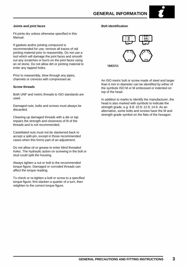
Bolt identification
An ISO metric bolt or screw made of steel and largerthan 6 mm in diameter can be identified by either ofthe symbols ISO M or M embossed or indented ontop of the head.
In addition to marks to identify the manufacturer, thehead is also marked with symbols to indicate thestrength grade, e.g. 8.8; 10.9; 12.9; 14.9. As analternative, some bolts and screws have the M andstrength grade symbol on the flats of the hexagon.

GENERAL INFORMATION
4 GENERAL PRECAUTIONS AND FITTING INSTRUCTIONS
Nut identification
A nut with an ISO metric thread is marked on oneface or on one of the flats of the hexagon with thestrength grade symbol 8, 12, or 14. Some nuts witha strength grade 4, 5 or 6 are also marked and somehave the metric symbol M on the flat opposite thestrength grade marking.
A clock face system is used as an alternativemethod of indicating the strength grade. Theexternal chambers or a face of the nut is marked in aposition relative to the appropriate hour mark on aclock face to indicate the strength grade.
A dot is used to locate the 12 o’clock position and adash to indicate the strength grade. If the grade isabove 12, two dots identify the 12 o’clock position.
Locking devices
Always release locking tabs and fit new lockingwashers, do not re-use locking tabs. Always use abacking spanner when slackening or tighteningbrake and fuel pipe unions.
Fitting a split pin
Always fit new split-pins of the correct size for thehole in the bolt or stud. Do not slacken back nut toenter split-pin.
Always fit new roll pins of an interference fit in thehole.
Always fit new circlips of the correct size for thegroove.
Self-locking nuts
Self-locking nuts, i.e. nylon insert or metal stiff nutscan be re-used providing resistance can be feltwhen the locking portion of the nut passes over thethread of the bolt or stud.

GENERAL INFORMATION
GENERAL PRECAUTIONS AND FITTING INSTRUCTIONS 5
Self-locking bolts and screws
Self-locking bolts and screws, i.e. nylon patched ortrilobular thread can be re-used providing resistancecan be felt when the locking portion enters thefemale thread.
Nylon patched bolts and screws have a lockingagent pre-applied to the threads. They are identifiedby the presence of a coloured section of threadwhich extends for up to 180° around the thread.
Trilobular i.e. Powerlok bolts have a special threadform which creates a slight interference in thetapped hole or threads of the nut into which it isscrewed.
DO NOT re-use self-locking fasteners in criticallocations eg engine bearings flywheel. Always usethe correct replacement self-locking nut, bolt orscrew.
DO NOT fit non self-locking fasteners in applicationswhere a self-locking nut, bolt or screw is specified.
Encapsulated bolts and screws
Encapsulated bolts and screws have amicro-encapsulated locking agent pre-applied to thethread. They are identified by the presence of acoloured section of thread which extends completelyaround the thread - 360°. The locking agent isreleased and activated by the assembly process andis then chemically cured to provide the lockingaction.
Unless a specific repair procedure states otherwise,encapsulated bolts may be re-used providing thethreads are undamaged and the following procedureis adopted.
Remove loose adhesive from the bolt and housingthreads, ensure threads are clean and free of oil andgrease. Apply an approved adhesive.
Fit a new encapsulated bolt, or if not available a boltof equivalent specification treated with an approvedadhesive.
GENERAL INFORMATION
6 GENERAL PRECAUTIONS AND FITTING INSTRUCTIONS
Oil seals
Always renew oil seals which have been removedfrom their working location either as an individualcomponent or as part of an assembly.
Ensure the surface on which the new seal is to run isfree of burrs or scratches. Renew the component ifthe original sealing surface cannot be completelyrestored.
Protect the seal from any surface which it has topass when being fitted. Use a protective sleeve ortape to cover the relevant surface.
Lubricate the sealing lips with a recommendedlubricant before use to prevent damage in initial use.On dual lipped seals, smear the area between thelips with grease.
Use the recommended service tool to fit an oil seal.
If the correct service tool is not available, use asuitable tube approximately 0.4 mm smaller than theoutside diameter of the seal.
Press or drift the seal in to the depth of its housing,with the sealing lip facing the lubricant to be retainedif the housing is shouldered, or flush with the face ofthe housing where no shoulder is provided.
Service tools and garage equipment
Special service tools have been developed tofacilitate removal, dismantling and assembly ofmechanical components in a cost effective andpractical manner without causing damage. Someoperations in this Manual cannot be carried outwithout the aid of the relevant service tools.
TestBook
TestBook is a computerised workshop tool whichprovides your dealership with instant access to thevery latest Technical Information from ROVER,allowing for accurate and effective fault diagnosisand repair of all Rover Vehicles.
Where specific garage equipment is required fordiagnosis and repair, reference should be made tothe Service Tools and Equipment Programme wheredetails of the equipment recommended by RoverService may be found.
Body repairs
Any damage found, that would affect the corrosionresistance of the vehicle during the Warranty periodmust be rectified by an authorised Rover Dealer tothe standards, and by the methods, detailed in theBody Repair Manual.
Replacement body panels
Body panels are supplied coated in cathodicelectrocoat primer.
Synthetic rubber
Many ’O’ rings, seals, hoses, flexible pipes and othersimilar items which appear to be natural rubber, arein fact, made of synthetic materials calledFluoroelastomers. Under normal operatingconditions this material is safe and does not presenta health hazard. However, if the material isdamaged by fire or excessive heating, it can breakdown and produce highly corrosive Hydrofluoric acidwhich can cause serious burns on contact with skin.If skin contact does occur:
• Remove any contaminated clothing immediately.• Irrigate effected area with a copious amount of
cold water or limewater for 15 to 60 minutes.• Obtain medical assistance immediately
Should the material be in a burnt or over-heatedcondition handle only with seamless industrialgloves. Decontaminate and dispose of lovesimmediately after use.

GENERAL INFORMATION
FUEL HANDLING PRECAUTIONS 1
FUEL HANDLING PRECAUTIONS
General
The following information provides basic precautionswhich must be observed if petrol (gasoline) is to behandled safely. It also outlines other areas of riskwhich must not be ignored. This information isissued for basic guidance only, and if in doubtappropriate enquiries should be made of your localFire Officer.
Petrol - Gasoline
Petrol/gasoline vapour is highly flammable and inconfined spaces is also explosive and toxic.
When petrol/gasoline evaporates it produces 150times its own volume in vapour which when dilutedwith air becomes a readily ignitable mixture. Thevapour is heavier than air and will always fall to thelowest level. It can readily be distributed throughouta workshop by air currents; consequently, even asmall spillage of petrol/ gasoline is potentially verydangerous.
Always have a fire extinguisher containing FOAM,CO2, GAS or POWDER close at hand whenhandling or draining fuel or when dismantling fuelsystems and in other areas where fuel containersare stored.
Always disconnect the vehicle battery beforecarrying out dismantling or draining work on a fuelsystem.
Whenever petrol/gasoline is being handled, drainedor stored or when fuel systems are beingdismantled, all forms of ignition must beextinguished or removed; any leadlamps must beflameproof and kept clear of spillage.
WARNING: No one should be permitted torepair components associated withpetrol/gasoline without first having
specialist training.
Fuel tank drainage
WARNING: Petrol/gasoline must not beextracted or drained from any vehiclewhilst it is standing over a pit.
Draining or extraction of petrol/gasoline from avehicle fuel tank must be carried out in a wellventilated area.The receptacle used to contain thepetrol/gasoline must be more than adequate forthe full amount of fuel to be extracted or drained.The receptacle should be clearly marked with itscontents, and placed in a safe storage areawhich meets the requirements of local authorityregulations.
CAUTION: When petrol/gasoline has beenextracted or drained from a fuel tank theprecautions governing naked lights and
ignition sources should be maintained.
Fuel tank removal
When the fuel line is secured to the fuel tank outletby a spring steel clip, the clip must be releasedbefore the fuel line is disconnected or the fuel tank isremoved. This procedure will avoid the possibility ofresidual petrol fumes in the fuel tank being ignitedwhen the clip is released.
As an added precaution fuel tanks should have a’PETROL (GASOLINE) VAPOUR’ warning labelattached to them as soon as they are removed fromthe vehicle.

GENERAL INFORMATION
2 FUEL HANDLING PRECAUTIONS
Fuel tank repairs
Under no circumstances should a repair to any fueltank involving heat treatment be carried out withoutfirst rendering the tank SAFE, by using one of thefollowing methods:
a. STEAMING: With the filler cap and tank unitremoved, empty the tank. Steam the tank for at leasttwo hours with low pressure steam. Position the tankso that condensation can drain away freely, ensuringthat any sediment and sludge not volatized by thesteam is washed out during the steaming process.
b. BOILING: With the filler cap and tank unitremoved, empty the tank. Immerse the tankcompletely in boiling water containing an effectivealkaline degreasing agent or a detergent, with thewater filling and also surrounding the tank for at leasttwo hours.
After steaming or boiling, a signed and dated label tothis effect should be attached to the tank.
Body and chassis repairs
When a body or chassis repairs involve the use ofheat, all fuel pipes which run in the vicinity of therepair area must be removed, and the tank outletplugged, BEFORE HEAT IS APPLIED. If the repairis in the vicinity of the fuel tank, the tank must beremoved.
Plastic fuel pipes are particularly susceptible to heat,even at relatively low temperature, and can bemelted by heat conducted from some distance away.
Fuel lines or tanks must not be removed whilst thevehicle is over an inspection pit.

GENERAL INFORMATION
ELECTRICAL PRECAUTIONS 1
ELECTRICAL PRECAUTIONS
General
The following guidelines are intended to ensure thesafety of the operator whilst preventing damage tothe electrical and electronic components fitted to thevehicle. Where necessary specific precautions aredetailed in the relevant sections of this Manual whichshould be referred to prior to commencing repairoperations.
Equipment - Prior to commencing any testprocedure on the vehicle ensure that the relevanttest equipment is working correctly and any harnessor connectors are in good condition, this particularlyapplies to mains lead and plugs.
WARNING: Before commencing work onan ignition system all high tensionterminals, adapters and diagnostic
equipment for testing should be inspected toensure that they are adequately insulated andshielded to prevent accidental personal contactsand minimise the risk of shock. Wearers ofsurgically implanted pacemaker devices shouldnot be in close proximity to ignition circuits ordiagnostic equipment.
Polarity - Never reverse connect the vehicle batteryand always observe the correct polarity whenconnecting test equipment.
High Voltage Circuits - Whenever disconnecting liveht circuits always use insulated pliers and neverallow the open end of the ht lead to come intocontact with other components particularly ECU’s.Exercise caution when measuring the voltage on thecoil terminals while the engine is running, highvoltage spikes can occur on these terminals.
Connectors and Harness - The engine compartmentof a vehicle is a particularly hostile environment forelectrical components and connectors. Alwaysensure these items are dry and oil free beforedisconnecting and connecting test equipment. Neverforce connectors apart either by using tools or bypulling on the wiring harness. Always ensure lockingtabs are disengaged before removal and notorientation to enable correct reconnection. Ensurethat any protective covers and substances arereplaced if disturbed.
Having confirmed a component to be faulty switchoff the ignition and disconnect the battery. Removethe component and support the disconnectedharness. When replacing the component keep oilyhands away from electrical connection areas andpush connectors home until any locking tabs fullyengage.
Battery disconnection
Before disconnecting the battery, switch off allelectrical equipment. If the radio is to be serviced,ensure the security code has been deactivated.
CAUTION: To prevent damage to electricalcomponents ALWAYS disconnect thebattery when working on the vehicle
electrical system. The earth lead must bedisconnected first and reconnected last.Always ensure that battery leads are routedcorrectly and are not close to any potentialchafing points.
Battery charging
Recharge the battery out of the vehicle and keep thetop well ventilated. While being charged ordischarged, and for approximately fifteen minutesafterwards, batteries emit hydrogen gas. This gas isinflammable.
Always ensure any battery charging area is wellventilated and that every precautions is taken toavoid naked flames and sparks.

GENERAL INFORMATION
2 ELECTRICAL PRECAUTIONS
Disciplines
Switch off ignition prior to making any connection ordisconnection in the system as electrical surgecaused by disconnecting ’live’ connections candamage electronic components.
Ensure hands and work surfaces are clean and freeof grease, swarf, etc. as grease collects dirt whichcan cause tracking or high-resistance contacts.
When handling printed circuit boards, treat them asyou would a disc - hold by the edges only; note thatsome electronic components are susceptible to bodystatic.
Connectors should never be subjected to forcedremoval or refit, especially inter-board connectors,damaged contacts will cause short- circuit andopen-circuit conditions.
Prior to commencing test, and periodically duringtest, touch a good earth, i.e. cigar lighter socket, todischarge body static as some electroniccomponents are vulnerable to static electricity.
Grease for electrical connectors
All under bonnet and under body connectors areprotected against corrosion by the application of aspecial grease on production. Should connectors bedisturbed in service or repaired or replaced, agrease of this type, available in 150 gm tubes underPart No. BAU 5811, should again be applied.
NOTE: The use of other greases must beavoided as they can migrate into relays,switches etc. contaminating the contacts
and leading to intermittent operation or failure.

INFORMATION
CONTENTS Page
LIFTING AND TOWING
JACKING, SUPPORTING AND TOWING 1................................................................WORKSHOP JACK 2..................................................................................................WHEEL-FREE LIFT 2..................................................................................................TOWING 2...................................................................................................................
GENERAL DATAENGINE 1....................................................................................................................FUEL SYSTEM 1.........................................................................................................COOLING SYSTEM 1..................................................................................................CLUTCH 2...................................................................................................................MANUAL GEARBOX 2................................................................................................AUTOMATIC GEARBOX 2..........................................................................................FINAL DRIVE 2............................................................................................................WHEELS 3...................................................................................................................TYRE SIZE 3...............................................................................................................TYRE PRESSURES 3.................................................................................................ELECTRICAL 3............................................................................................................DIMENSIONS 4...........................................................................................................WEIGHTS 4.................................................................................................................
ENGINE TUNING DATAModel: SPi with manual gearbox 1..............................................................................Model: SPi with automatic gearbox 2...........................................................................Model: MPi 3................................................................................................................
TORQUE WRENCH SETTINGSGENERAL 1.................................................................................................................ENGINE 1....................................................................................................................EMISSION CONTROL 2..............................................................................................ENGINE MANAGEMENT SYSTEM 2..........................................................................FUEL SYSTEM 2.........................................................................................................COOLING 2.................................................................................................................MANIFOLD AND EXHAUST 3.....................................................................................CLUTCH 3...................................................................................................................MANUAL GEARBOX 3................................................................................................STEERING 3...............................................................................................................SUSPENSION 4..........................................................................................................BRAKES 4...................................................................................................................RESTRAINT SYSTEMS 4...........................................................................................BODY 5........................................................................................................................HEATING AND VENTILATION 5.................................................................................WIPERS AND WASHERS 5........................................................................................ELECTRICAL 5............................................................................................................INSTRUMENTS 5........................................................................................................
CAPACITIES, FLUIDS AND LUBRICANTSCAPACITIES 1.............................................................................................................FLUIDS 1.....................................................................................................................LUBRICATION 2..........................................................................................................


INFORMATION
LIFTING AND TOWING 1
JACKING, SUPPORTING AND TOWING
Jacking and support points
1. Lashing/towing eye - front2. LH floor front reinforcement3. RH floor front reinforcement4. Sill reinforced brackets - front5. LH subframe longitudinal - front
6. RH subframe longitudinal - front7. Sill reinforced brackets - rear8. RH subframe longitudinal - rear9. LH subframe longitudinal - rear
10. Lashing eye - rear
WARNING: In accordance with normalworkshop practice and to avoid thepossibility of damage or personal injury,
work must not be carried out on or under avehicle when it is supported solely on a jack.Place safety supports under the sill reinforcedbrackets (4 and 7).
WARNING: Do not position a jack, jackstand or wheel free support under thesubframe transverse members.
CAUTION: Use suitable hardwood orrubber pads when jacking and supportingthe vehicle.
INFORMATION
2 LIFTING AND TOWING
WORKSHOP JACK
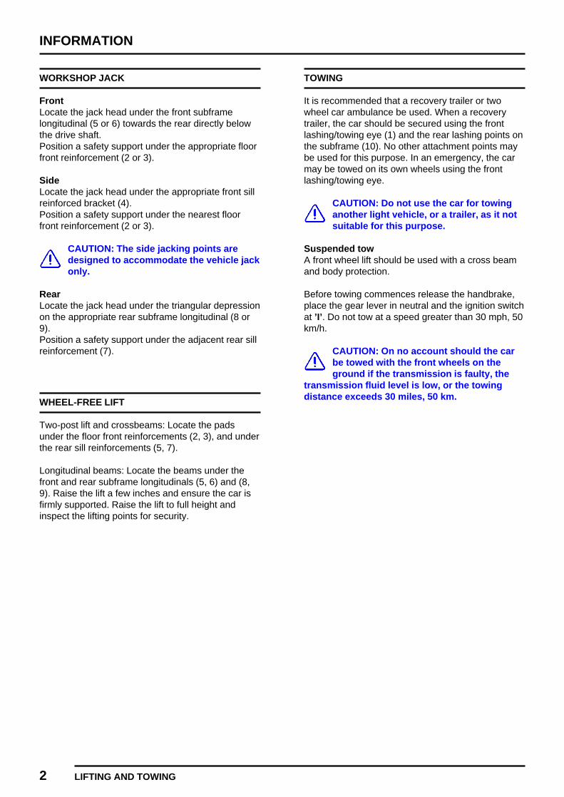
FrontLocate the jack head under the front subframelongitudinal (5 or 6) towards the rear directly belowthe drive shaft.Position a safety support under the appropriate floorfront reinforcement (2 or 3).
SideLocate the jack head under the appropriate front sillreinforced bracket (4).Position a safety support under the nearest floorfront reinforcement (2 or 3).
CAUTION: The side jacking points aredesigned to accommodate the vehicle jackonly.
RearLocate the jack head under the triangular depressionon the appropriate rear subframe longitudinal (8 or9).Position a safety support under the adjacent rear sillreinforcement (7).
WHEEL-FREE LIFT
Two-post lift and crossbeams: Locate the padsunder the floor front reinforcements (2, 3), and underthe rear sill reinforcements (5, 7).
Longitudinal beams: Locate the beams under thefront and rear subframe longitudinals (5, 6) and (8,9). Raise the lift a few inches and ensure the car isfirmly supported. Raise the lift to full height andinspect the lifting points for security.
TOWING
It is recommended that a recovery trailer or twowheel car ambulance be used. When a recoverytrailer, the car should be secured using the frontlashing/towing eye (1) and the rear lashing points onthe subframe (10). No other attachment points maybe used for this purpose. In an emergency, the carmay be towed on its own wheels using the frontlashing/towing eye.
CAUTION: Do not use the car for towinganother light vehicle, or a trailer, as it notsuitable for this purpose.
Suspended towA front wheel lift should be used with a cross beamand body protection.
Before towing commences release the handbrake,place the gear lever in neutral and the ignition switchat ’I’. Do not tow at a speed greater than 30 mph, 50km/h.
CAUTION: On no account should the carbe towed with the front wheels on theground if the transmission is faulty, the
transmission fluid level is low, or the towingdistance exceeds 30 miles, 50 km.

INFORMATION
LIFTING AND TOWING 3
Manual gearbox modelsUse the front lashing/towing eye (1) for towing thecar on all four wheels from the front.
WARNING: To ensure that the steeringdoes not lock when the car is being towed,it is essential that the starter key is turned
to position ’I’, and remains there while the car ismoving.Ensure the following precautions are observed:Do not tow if the gearbox or a drive shaft isfaulty.Do not tow if a wheel or drive shafts are touchingthe body or frame.Ensure the gear lever is in neutral and thehandbrake is released.Remember that greater effort than normal will benecessary to apply the brakes if the car is beingtowed without the engine running.
Automatic gearbox modelsWhen a car with an automatic gearbox is to betowed, a suspended tow must be used because thegearbox is not adequately lubricated without theengine running. The following precautions must beobserved:
The selector must be at ’N’.
CAUTION: A rear suspended tow must notbe attempted as serious damage will becaused to the automatic transmission.
NOTE: A vehicle fitted with an automaticgearbox cannot be started by towing orpushing.


INFORMATION
GENERAL DATA 1REVISED: 12/96
ENGINE
Type 8 valve OHV. . . . . . . . . . . . . . . . . . . . . . . . . . . . . . . . . . . . . .Cylinder arrangement 4 in line - transverse. . . . . . . . . . . . . . . . . . . . . . . .Bore 70.61 mm. . . . . . . . . . . . . . . . . . . . . . . . . . . . . . . . . . . . . .Stroke 81.28 mm. . . . . . . . . . . . . . . . . . . . . . . . . . . . . . . . . . . .Capacity 1275 cm3. . . . . . . . . . . . . . . . . . . . . . . . . . . . . . . . . . .Firing order 1 - 3 - 4 - 2. . . . . . . . . . . . . . . . . . . . . . . . . . . . . . . .Rotation Clockwise, viewed from front of engine. . . . . . . . . . . . . . . . . . . . . . . . . . . . . . . . . . .Compression ratio 10.0 : 1. . . . . . . . . . . . . . . . . . . . . . . . . . .
Valve timingInlet:Opens 9°BTDC. . . . . . . . . . . . . . . . . . . . . . . . . . . . . . . . . . .Closes 41°ABDC. . . . . . . . . . . . . . . . . . . . . . . . . . . . . . . . . . .
Exhaust:Opens 55°BBDC. . . . . . . . . . . . . . . . . . . . . . . . . . . . . . . . . . .Closes 17°ATDC. . . . . . . . . . . . . . . . . . . . . . . . . . . . . . . . . . .
LubricationSystem type Wet sump, crankshaft driven eccentric rotor pump. . . . . . . . . . . . . . . . . . . . . . . . . . . . . . . .Relief valve opening pressure 2.0 bar. . . . . . . . . . . . . . . . . .Pressure at idle 0.5 bar. . . . . . . . . . . . . . . . . . . . . . . . . . . . .Oil pressure warning light switch opens 0.2 to 0.3 bar. . . . . . . . . .Oil filter Full flow with disposable canister. . . . . . . . . . . . . . . . . . . . . . . . . . . . . . . . . . .
FUEL SYSTEM
Electronic fuel injection data See Engine Tuning Data. . . . . . . . . . . . . . . . . . .Fuel Pump:Type Electric immersible. . . . . . . . . . . . . . . . . . . . . . . . . . . . . . . . . . . . .Pump maximum pressure at 16V 2.7 bar. . . . . . . . . . . . . .Regulated injection pressure range 1.0 to 3.0 bar ± 0.2 bar. . . . . . . . . . . . .
COOLING SYSTEM
Pressure cap opens 0.5 bar. . . . . . . . . . . . . . . . . . . . . . . . . .Thermostat starts to open 88°C ± 2°. . . . . . . . . . . . . . . . . . . . .Thermostat fully open 100°C ± 2°. . . . . . . . . . . . . . . . . . . . . . . .Cooling fan operation:On 105°C. . . . . . . . . . . . . . . . . . . . . . . . . . . . . . . . . . . . . .Off 98°C. . . . . . . . . . . . . . . . . . . . . . . . . . . . . . . . . . . . . .

INFORMATION
2 GENERAL DATA
CLUTCH
Type Diaphragm spring, hydraulically operated. . . . . . . . . . . . . . . . . . . . . . . . . . . . . . . . . . . . . .Clutch plate diameter 180 mm. . . . . . . . . . . . . . . . . . . . . . . . .
MANUAL GEARBOX
Gear ratios:Fourth 1.000 : 1. . . . . . . . . . . . . . . . . . . . . . . . . . . . . . . . . . .Third 1.425 : 1. . . . . . . . . . . . . . . . . . . . . . . . . . . . . . . . . . . .Second 2.185 : 1. . . . . . . . . . . . . . . . . . . . . . . . . . . . . . . . . .First 3.647 : 1. . . . . . . . . . . . . . . . . . . . . . . . . . . . . . . . . . . . .Reverse 3.667 : 1. . . . . . . . . . . . . . . . . . . . . . . . . . . . . . . . . .
AUTOMATIC GEARBOX
Type 3-speed, torque converter. . . . . . . . . . . . . . . . . . . . . . . . . . . . . . . . . . . . . .Gear ratios:Drive 1.000 : 1. . . . . . . . . . . . . . . . . . . . . . . . . . . . . . . . . . . .Third 1.460 : 1. . . . . . . . . . . . . . . . . . . . . . . . . . . . . . . . . . . .Second 1.845 : 1. . . . . . . . . . . . . . . . . . . . . . . . . . . . . . . . . .First 2.690 : 1. . . . . . . . . . . . . . . . . . . . . . . . . . . . . . . . . . . . .Reverse 2.690 : 1. . . . . . . . . . . . . . . . . . . . . . . . . . . . . . . . . .
FINAL DRIVE
Manual gearbox:Ratio 3.213 : 1. . . . . . . . . . . . . . . . . . . . . . . . . . . . . . . . . . . .Road speed at 1000 rev/min:Fourth 28.6 km/h. . . . . . . . . . . . . . . . . . . . . . . . . . . . . . . . . . . 17.8 mphThird 20.1 km/h. . . . . . . . . . . . . . . . . . . . . . . . . . . . . . . . . . . . 12.5 mphSecond 13.1 km/h. . . . . . . . . . . . . . . . . . . . . . . . . . . . . . . . . . 8.2 mphFirst 7.9 km/h. . . . . . . . . . . . . . . . . . . . . . . . . . . . . . . . . . . . . 4.9 mph
Automatic gearbox:Ratio 2.690 : 1. . . . . . . . . . . . . . . . . . . . . . . . . . . . . . . . . . . .Road speed at 1000 rev/min:Drive 29.3 km/h. . . . . . . . . . . . . . . . . . . . . . . . . . . . . . . . . . . . 18.2 mphThird 20.1 km/h. . . . . . . . . . . . . . . . . . . . . . . . . . . . . . . . . . . . 12.5 mphSecond 15.9 km/h. . . . . . . . . . . . . . . . . . . . . . . . . . . . . . . . . . 9.9 mphFirst 10.1 km/h. . . . . . . . . . . . . . . . . . . . . . . . . . . . . . . . . . . . . 6.8 mph
INFORMATION
GENERAL DATA 3
WHEELS
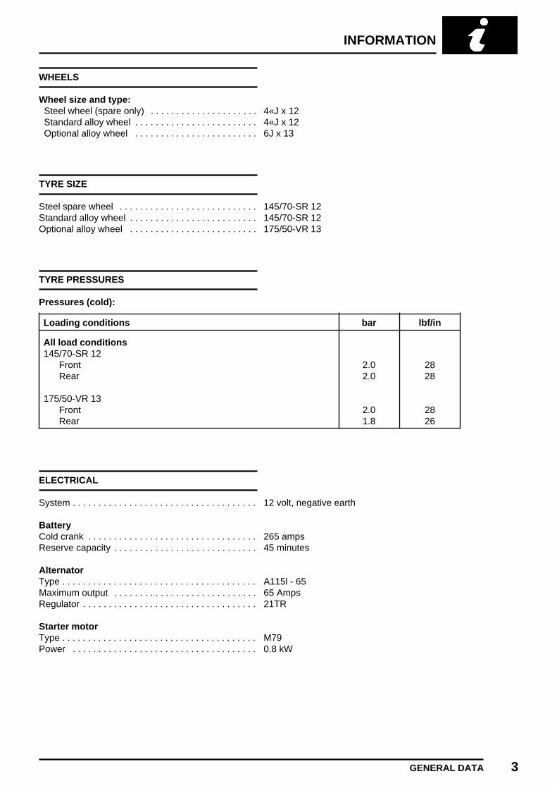
Wheel size and type:Steel wheel (spare only) 4«J x 12. . . . . . . . . . . . . . . . . . . . .Standard alloy wheel 4«J x 12. . . . . . . . . . . . . . . . . . . . . . . .Optional alloy wheel 6J x 13. . . . . . . . . . . . . . . . . . . . . . . .
TYRE SIZE
Steel spare wheel 145/70-SR 12. . . . . . . . . . . . . . . . . . . . . . . . . . .Standard alloy wheel 145/70-SR 12. . . . . . . . . . . . . . . . . . . . . . . . .Optional alloy wheel 175/50-VR 13. . . . . . . . . . . . . . . . . . . . . . . . .
TYRE PRESSURES
Pressures (cold):
Loading conditions bar lbf/in
All load conditions145/70-SR 12
Front 2.0 28Rear 2.0 28
175/50-VR 13Front 2.0 28Rear 1.8 26
ELECTRICAL
System 12 volt, negative earth. . . . . . . . . . . . . . . . . . . . . . . . . . . . . . . . . . . .
BatteryCold crank 265 amps. . . . . . . . . . . . . . . . . . . . . . . . . . . . . . . . .Reserve capacity 45 minutes. . . . . . . . . . . . . . . . . . . . . . . . . . . .
AlternatorType A115l - 65. . . . . . . . . . . . . . . . . . . . . . . . . . . . . . . . . . . . . .Maximum output 65 Amps. . . . . . . . . . . . . . . . . . . . . . . . . . . .Regulator 21TR. . . . . . . . . . . . . . . . . . . . . . . . . . . . . . . . . .
Starter motorType M79. . . . . . . . . . . . . . . . . . . . . . . . . . . . . . . . . . . . . .Power 0.8 kW. . . . . . . . . . . . . . . . . . . . . . . . . . . . . . . . . . . .

INFORMATION
4 GENERAL DATA
DIMENSIONS
Overall length 3.05 m. . . . . . . . . . . . . . . . . . . . . . . . . . . . . .Overall width (including mirrors) 1.58 m. . . . . . . . . . . . . . . .Overall height * 1.34 m. . . . . . . . . . . . . . . . . . . . . . . . . . . . .Ground clearance * 163 mm. . . . . . . . . . . . . . . . . . . . . . . . . .Wheelbase 2.04 m. . . . . . . . . . . . . . . . . . . . . . . . . . . . . . . . .Turning circle (kerb to kerb):145/70 SR-12 tyres 8.60 m. . . . . . . . . . . . . . . . . . . . . . . . .175/VR-13 tyres 8.80 m. . . . . . . . . . . . . . . . . . . . . . . . . . . .
* At unladen weight
WEIGHTS
Unladen (fuel tank full, excluding optional fittings) 715 kg. . .Maximum gross vehicle weight 1050 kg. . . . . . . . . . . . . . . . .Maximum roof rack load (distributed) 50 kg. . . . . . . . . . . .
CAUTION: Do not use the vehicle for towing a trailer, as it is not suitable for this purpose.

INFORMATION
ENGINE TUNING DATA 1
Model: SPi with manual gearbox
EngineType / Capacity 12A2EK71/1275 cm3. . . . . . . . . . . . . . . . . . . . . . . . . . . . .Firing order 1 - 3 - 4 - 2. . . . . . . . . . . . . . . . . . . . . . . . . . . . . . . .Compression ratio 10.0 : 1. . . . . . . . . . . . . . . . . . . . . . . . . . .Idle speed, controlled by the ECM * 900 æ 50 rev/min. . . . . . . . . . . . .Exhaust gas CO content at idle less than 0.4% hot. . . . . . . . . . . . . . . . .Ignition timing at idle speed c 15°BTDC (nominal). . . . . . . . . . . . . . . . . .Valve rocker clearance (cold) 0.27 to 0.33 mm. . . . . . . . . . . . . . . . . .
Ignition CoilType Quad type dry. . . . . . . . . . . . . . . . . . . . . . . . . . . . . . . . . . . . . .Part No. NEC 1000710. . . . . . . . . . . . . . . . . . . . . . . . . . . . . . . . . . .Primary resistance at 20°C 0.41 to 0.61 ohm. . . . . . . . . . . . . . . . . . . .Secondary resistance at 20°C 6200 to 6700 ohm. . . . . . . . . . . . . . . . . .Consumption at engine idle speed 4.7 to 6.7 amps. . . . . . . . . . . . . .
Spark PlugsType NGK BPR6E. . . . . . . . . . . . . . . . . . . . . . . . . . . . . . . . . . . . . .Plug gap 0.80 to 0.90 mm. . . . . . . . . . . . . . . . . . . . . . . . . . . . . . . . . .
Engine Management SystemType Single point throttle body injection. . . . . . . . . . . . . . . . . . . . . . . . . . . . . . . . . . . . . .MEMS ECM MNE 101350. . . . . . . . . . . . . . . . . . . . . . . . . . . . . . . .Fuel pump module WFX 10047. . . . . . . . . . . . . . . . . . . . . . . . . . .Injector/fuel pressure regulator JZX 3300. . . . . . . . . . . . . . . .Fuel pressure 1.0 æ 0.2 bar constant. . . . . . . . . . . . . . . . . . . . . . . . . . . . . .
Throttle position (TP) sensor MJC 10020. . . . . . . . . . . . . . . . . . .Intake air temperature (IAT) sensor NNK 10001. . . . . . . . . . . . . .Crankshaft position (CKP) sensor ADU 7340. . . . . . . . . . . . . . .Engine coolant temperature (ECT) sensor ADU 7161. . . . . . . .Heated oxygen sensor (HO2S) MHK 10004. . . . . . . . . . . . . . . . .Lost motion gap at engine idle speed Equal either side of lever. . . . . . . . . . . .TP sensor voltage:Throttle closed 0 to 1v. . . . . . . . . . . . . . . . . . . . . . . . . . . . .Throttle open 90° 4 to 5v. . . . . . . . . . . . . . . . . . . . . . . . . . .Throttle open 65° 3 to 4v. . . . . . . . . . . . . . . . . . . . . . . . . . .
Fuel grade 95 RON minimum - UNLEADED fuel. . . . . . . . . . . . . . . . . . . . . . . . . . . . . . . . .
CAUTION: Do not use LEADED fuel as it will damage the catalyst. Serious damage to the engine mayoccur if a lower octane number fuel than that recommended is used.
* No electrical load present
c Crankshaft degrees and rev/min

INFORMATION
2 ENGINE TUNING DATA
Model: SPi with automatic gearbox
EngineType / Capacity 12A2EK72/1275 cm3. . . . . . . . . . . . . . . . . . . . . . . . . . . . .Firing order 1 - 3 - 4 - 2. . . . . . . . . . . . . . . . . . . . . . . . . . . . . . . .Compression ratio 9.4 : 1. . . . . . . . . . . . . . . . . . . . . . . . . . .Idle speed, controlled by the ECM * 900 æ 50 rev/min. . . . . . . . . . . . .Exhaust gas CO content at idle less than 0.4% hot. . . . . . . . . . . . . . . . .Ignition timing at idle speed c 15°BTDC (nominal). . . . . . . . . . . . . . . . . .Valve rocker clearance (cold) 0.27 to 0.33 mm. . . . . . . . . . . . . . . . . .
Ignition CoilType Quad type dry. . . . . . . . . . . . . . . . . . . . . . . . . . . . . . . . . . . . . .Part No. NEC 1000710. . . . . . . . . . . . . . . . . . . . . . . . . . . . . . . . . . .Primary resistance at 20°C 0.41 to 0.61 ohm. . . . . . . . . . . . . . . . . . . .Secondary resistance at 20°C 6200 to 6700 ohm. . . . . . . . . . . . . . . . . .Consumption at engine idle speed 4.7 to 6.7 amps. . . . . . . . . . . . . .
Spark PlugsType NGK BPR6E. . . . . . . . . . . . . . . . . . . . . . . . . . . . . . . . . . . . . .Plug gap 0.80 to 0.90 mm. . . . . . . . . . . . . . . . . . . . . . . . . . . . . . . . . .
Engine Management SystemType Single point throttle body injection. . . . . . . . . . . . . . . . . . . . . . . . . . . . . . . . . . . . . .MEMS ECM MNE 101350. . . . . . . . . . . . . . . . . . . . . . . . . . . . . . . .Fuel pump module WFX 10047. . . . . . . . . . . . . . . . . . . . . . . . . . .Injector/fuel pressure regulator JZX 3300. . . . . . . . . . . . . . . .Fuel pressure 1.0 æ 0.2 bar constant. . . . . . . . . . . . . . . . . . . . . . . . . . . . . .
Throttle position (TP) sensor MJC 10020. . . . . . . . . . . . . . . . . . .Intake air temperature (IAT) sensor NNK 10001. . . . . . . . . . . . . .Crankshaft position (CKP) sensor ADU 7340. . . . . . . . . . . . . . .Engine coolant temperature (ECT) sensor ADU 7161. . . . . . . .Heated oxygen sensor (HO2S) MHK 10004. . . . . . . . . . . . . . . . .Lost motion gap at engine idle speed Equal either side of lever. . . . . . . . . . . .TP sensor voltage:Throttle closed 0 to 1v. . . . . . . . . . . . . . . . . . . . . . . . . . . . .Throttle open 90° 4 to 5v. . . . . . . . . . . . . . . . . . . . . . . . . . .Throttle open 65° 3 to 4v. . . . . . . . . . . . . . . . . . . . . . . . . . .
Fuel grade 95 RON minimum - UNLEADED fuel. . . . . . . . . . . . . . . . . . . . . . . . . . . . . . . . .
CAUTION: Do not use LEADED fuel as it will damage the catalyst. Serious damage to the engine mayoccur if a lower octane number fuel than that recommended is used.
* No electrical load present
c Crankshaft degrees and rev/min

INFORMATION
ENGINE TUNING DATA 3
Model: MPi
EngineType / Capacity 12A2LK70/1275 cm3. . . . . . . . . . . . . . . . . . . . . . . . . . . . .Firing order 1 - 3 - 4 - 2. . . . . . . . . . . . . . . . . . . . . . . . . . . . . . . .Compression ratio 10.0 : 1. . . . . . . . . . . . . . . . . . . . . . . . . . .Idle speed, controlled by the ECM * 900 æ 50 rev/min. . . . . . . . . . . . .Exhaust gas CO content at idle less than 0.4% hot. . . . . . . . . . . . . . . . .Ignition timing at idle speed c 12°BTDC (nominal). . . . . . . . . . . . . . . . . .Valve rocker clearance (cold) 0.27 to 0.33 mm. . . . . . . . . . . . . . . . . .
Ignition CoilType Quad type dry. . . . . . . . . . . . . . . . . . . . . . . . . . . . . . . . . . . . . .Part No. NEC 1000710. . . . . . . . . . . . . . . . . . . . . . . . . . . . . . . . . . .Primary resistance at 20°C 0.41 to 0.61 ohm. . . . . . . . . . . . . . . . . . . .Secondary resistance at 20°C 6200 to 6700 ohm. . . . . . . . . . . . . . . . . .Consumption at engine idle speed 4.7 to 6.7 amps. . . . . . . . . . . . . .
Spark PlugsType NGK BPR6E. . . . . . . . . . . . . . . . . . . . . . . . . . . . . . . . . . . . . .Plug gap 0.80 to 0.90 mm. . . . . . . . . . . . . . . . . . . . . . . . . . . . . . . . . .
Engine Management SystemType Two point injection. . . . . . . . . . . . . . . . . . . . . . . . . . . . . . . . . . . . . .MEMS ECM MNE 104290. . . . . . . . . . . . . . . . . . . . . . . . . . . . . . . .Fuel pump module WFX 100810. . . . . . . . . . . . . . . . . . . . . . . . . . .Injector/fuel pressure regulator MKW 10016. . . . . . . . . . . . . . . .Fuel pressure 3.0 æ 0.2 bar constant. . . . . . . . . . . . . . . . . . . . . . . . . . . . . .
Throttle position (TP) sensor MJC 10020. . . . . . . . . . . . . . . . . . .Intake air temperature (IAT) sensor NNK 10001. . . . . . . . . . . . . .Crankshaft position (CKP) sensor ADU 7340. . . . . . . . . . . . . . .Camshaft position (CMP) sensor NSC 100390. . . . . . . . . . . . . . . .Engine coolant temperature (ECT) sensor MEK 100060. . . . . . . .Heated oxygen sensor (HO2S) MHK 10004. . . . . . . . . . . . . . . . .TP sensor voltage:Throttle closed 0 to 1v. . . . . . . . . . . . . . . . . . . . . . . . . . . . .Throttle open 90° 4 to 5v. . . . . . . . . . . . . . . . . . . . . . . . . . .Throttle open 65° 3 to 4v. . . . . . . . . . . . . . . . . . . . . . . . . . .
Fuel grade 95 RON minimum - UNLEADED fuel. . . . . . . . . . . . . . . . . . . . . . . . . . . . . . . . .
CAUTION: Do not use LEADED fuel as it will damage the catalyst. Serious damage to the engine mayoccur if a lower octane number fuel than that recommended is used.
* No electrical load present
c Crankshaft degrees and rev/min


INFORMATION
TORQUE WRENCH SETTINGS 1REVISED: 12/96
Refer to the appropriate section heading for component torque figures, e.g.Road wheel nuts - refer to SUSPENSION,Exhaust front pipe to manifold - refer to MANIFOLD AND EXHAUST
GENERAL
Bolt M6 10 Nm. . . . . . . . . . . . . . . . . . . . . . . . . . . . . . . . . . .Bolt M8 25 Nm. . . . . . . . . . . . . . . . . . . . . . . . . . . . . . . . . . .Bolt M10 45 Nm. . . . . . . . . . . . . . . . . . . . . . . . . . . . . . . . . .Bolt M12 80 Nm. . . . . . . . . . . . . . . . . . . . . . . . . . . . . . . . . .1/4 UNC/UNF 9 Nm. . . . . . . . . . . . . . . . . . . . . . . . . . . . . .5/16 UNC/UNF 25 Nm. . . . . . . . . . . . . . . . . . . . . . . . . . . . .3/8 UNC/UNF 40 Nm. . . . . . . . . . . . . . . . . . . . . . . . . . . . . .7/16 UNC/UNF 75 Nm. . . . . . . . . . . . . . . . . . . . . . . . . . . . .1/2 UNC/UNF 90 Nm. . . . . . . . . . . . . . . . . . . . . . . . . . . . . .5/8 UNC/UNF 135 Nm. . . . . . . . . . . . . . . . . . . . . . . . . . . . . .
ENGINE
Timing gear cover bolts 16 Nm. . . . . . . . . . . . . . . . . . . . . . .Timing gear nuts 90 Nm. . . . . . . . . . . . . . . . . . . . . . . . . . . .Timing chain tensioner bolts 22 Nm. . . . . . . . . . . . . . . . . . .Cylinder head nuts 34 Nm then a further 34 Nm. . . . . . . . . . . . . . . . . . . . . . . . . . .Front cover plate bolts 11 Nm. . . . . . . . . . . . . . . . . . . . . . . .Rocker shaft nuts 25 Nm. . . . . . . . . . . . . . . . . . . . . . . . . . . .Camshaft thrust plate screws 11 Nm. . . . . . . . . . . . . . . . . .Rocker cover bolts 5 Nm. . . . . . . . . . . . . . . . . . . . . . . . . . .Crankshaft pulley bolt 150 Nm. . . . . . . . . . . . . . . . . . . . . . . .Engine LH mounting:Mounting to subframe - nuts 25 Nm. . . . . . . . . . . . . . . . . .Mounting to engine - bolts 25 Nm. . . . . . . . . . . . . . . . . . . .
Engine RH mounting:Mounting to flywheel housing cover - bolts 18 Nm. . . . . . .Mounting to subframe - nuts 22 Nm. . . . . . . . . . . . . . . . . .
Engine steady bar upper bolts 22 Nm. . . . . . . . . . . . . . . . . .Engine steady bar lower:Bar to subframe bolt 40 Nm. . . . . . . . . . . . . . . . . . . . . . . .Bar to flywheel housing bolt 40 Nm. . . . . . . . . . . . . . . . . . .
Oil pressure gauge sensor 60 Nm. . . . . . . . . . . . . . . . . . . .Oil pressure relief valve cap 60 Nm. . . . . . . . . . . . . . . . . . .Oil pressure switch 25 Nm. . . . . . . . . . . . . . . . . . . . . . . . . .Oil pump to engine - bolts 11 Nm. . . . . . . . . . . . . . . . . . . . .Flywheel housing to engine/gearbox - bolts 25 Nm. . . . . . .Earth lead to engine - bolt 10 Nm. . . . . . . . . . . . . . . . . . . . .Engine to gearbox - nuts and bolts 8 Nm. . . . . . . . . . . . . .Flywheel to crankshaft - bolt 150 Nm. . . . . . . . . . . . . . . . . . .Flywheel housing cover - bolts 10 Nm. . . . . . . . . . . . . . . . .Engine mounting adaptor plate to engine - bolts 25 Nm. . . .

INFORMATION
2 TORQUE WRENCH SETTINGS REVISED: 12/96
EMISSION CONTROL
Oil breather/separator to flywheel housing 18 Nm. . . . . . . .Catalytic converter to tail pipe nuts 9 Nm. . . . . . . . . . . . . .Catalytic converter to front pipe nuts 45 Nm. . . . . . . . . . . . .Emission canister purge valve to body - bolts 9 Nm. . . . . .
ENGINE MANAGEMENT SYSTEM
ECT sensor to thermostat housing 15 Nm. . . . . . . . . . . . . .MAP sensor to inlet manifold 6 Nm. . . . . . . . . . . . . . . . . . .IAT sensor to inlet manifold 7 Nm. . . . . . . . . . . . . . . . . . . .TP sensor to throttle body screws 1.5 Nm. . . . . . . . . . . . . . .Throttle housing to inlet mainifold - bolts 8 Nm. . . . . . . . . .Throttle pedal nuts 25 Nm. . . . . . . . . . . . . . . . . . . . . . . . . . .Spark plugs 25 Nm. . . . . . . . . . . . . . . . . . . . . . . . . . . . . . . .Ignition coil to bracket - bolts 10 Nm. . . . . . . . . . . . . . . . . . .HO2S to exhaust manifold 55 Nm. . . . . . . . . . . . . . . . . . . . .Air cleaner to inlet manifold 7 Nm. . . . . . . . . . . . . . . . . . . .ECM to mounting bracket 10 Nm. . . . . . . . . . . . . . . . . . . . .ECM mounting bracket to body 10 Nm. . . . . . . . . . . . . . . . .IACV to inlet manifold - bolts 7 Nm. . . . . . . . . . . . . . . . . . .CMP sensor to engine - bolt 10 Nm. . . . . . . . . . . . . . . . . . .CKP sensor to flywheel housing - bolts 6 Nm. . . . . . . . . . .CKP sensor multiplug to flywheel housing - bolt 3 Nm. . . .
FUEL SYSTEM
Fuel breather valve nut 9 Nm. . . . . . . . . . . . . . . . . . . . . . .Fuel pump to fuel tank nuts 9 Nm. . . . . . . . . . . . . . . . . . . .IFS to bulkhead - screws 2 Nm. . . . . . . . . . . . . . . . . . . . . .Fuel filter mounting bracket to body 9 Nm. . . . . . . . . . . . . .Fuel pipe unions to fuel filter 30 Nm. . . . . . . . . . . . . . . . . . .Fuel feed/return pipes to fuel rail 5 Nm. . . . . . . . . . . . . . . .Fuel rail to inlet manifold - bolts 10 Nm. . . . . . . . . . . . . . . . .
COOLING
Radiator brackets to bonnet platform 9 Nm. . . . . . . . . . . . .Thermostat housing bolts 11 Nm. . . . . . . . . . . . . . . . . . . . .Coolant pump bolts 22 Nm. . . . . . . . . . . . . . . . . . . . . . . . . .Coolant pump pulley bolts 10 Nm. . . . . . . . . . . . . . . . . . . . .Expansion tank to mounting bracket 10 Nm. . . . . . . . . . . . .Expansion tank mounting bracket to body 10 Nm. . . . . . . . .

INFORMATION
TORQUE WRENCH SETTINGS 3REVISED: 12/96
MANIFOLD AND EXHAUST
Front pipe to manifold nuts 22 Nm. . . . . . . . . . . . . . . . . . . .Front pipe to differential housing 22 Nm. . . . . . . . . . . . . . . .Inlet and exhaust manifold nuts 22 Nm. . . . . . . . . . . . . . . . .Catalytic converter to tail pipe nuts 9 Nm. . . . . . . . . . . . . .Catalytic converter to front pipe nuts 45 Nm. . . . . . . . . . . . .
CLUTCH
Flywheel centre bolt 150 Nm. . . . . . . . . . . . . . . . . . . . . . . . . .Pressure plate to flywheel bolts 25 Nm. . . . . . . . . . . . . . . . .Flywheel housing to engine block bolts 25 Nm. . . . . . . . . . .Slave cylinder to mounting bracket 37 Nm. . . . . . . . . . . . . .Slave cylinder mounting bracket to flywheelhousing:M8 bolts 37 Nm. . . . . . . . . . . . . . . . . . . . . . . . . . . . . . . . . .M5 bolt 7 Nm. . . . . . . . . . . . . . . . . . . . . . . . . . . . . . . . . . .
Pipe union to master cylinder 14 Nm. . . . . . . . . . . . . . . . . .Pipe union to slave cylinder 14 Nm. . . . . . . . . . . . . . . . . . . .
MANUAL GEARBOX
Gearbox to engine bolts 28 Nm. . . . . . . . . . . . . . . . . . . . . .Third motion shaft bearing retaining bolts 18 Nm. . . . . . . . .First motion shaft gear nut 200 Nm. . . . . . . . . . . . . . . . . . . . .Speedometer drive housing to gearbox - bolts 25 Nm. . . . .Speedometer drive housing cover - bolts 8 Nm. . . . . . . . .Speedometer drive pinion clamping plate - bolt 8 Nm. . . . .
STEERING
Steering wheel nut 49 Nm. . . . . . . . . . . . . . . . . . . . . . . . . . .Drivers air bag module Torx screws 9 Nm. . . . . . . . . . . . .Steering column upper mounting to fascia rail bolt 25 Nm. .Inner column to steering rack pinion clamp bolt 16 Nm. . . .Track rod ball joint to steering arm nut 30 Nm. . . . . . . . . . .Steering rack U-bolts 15 Nm. . . . . . . . . . . . . . . . . . . . . . . . .Steering rack pinion cover bolts 15 Nm. . . . . . . . . . . . . . . . .Steering arm to front hub bolts 45 Nm. . . . . . . . . . . . . . . . .Steering column to pinion - bolt 15 Nm. . . . . . . . . . . . . . . . .

INFORMATION
4 TORQUE WRENCH SETTINGS REVISED: 12/96
SUSPENSION
Wheel nuts:Alloy wheels 50 Nm. . . . . . . . . . . . . . . . . . . . . . . . . . . . . . .Steel wheels 60 Nm. . . . . . . . . . . . . . . . . . . . . . . . . . . . . .
Upper arm to front hub 52 Nm. . . . . . . . . . . . . . . . . . . . . . .Lower arm to front hub 52 Nm. . . . . . . . . . . . . . . . . . . . . . .Front hub to drive shaft - nut 260 Nm. . . . . . . . . . . . . . . . . . .Front subframe turret bolts 67 Nm. . . . . . . . . . . . . . . . . . . .Front damper to body bracket - nut 37 Nm. . . . . . . . . . . . . .Front damper to upper arm - nut 48 Nm. . . . . . . . . . . . . . . .Front subframe to body - nuts and bolts 25 Nm. . . . . . . . . .Rear damper to body 25 Nm. . . . . . . . . . . . . . . . . . . . . . . . .Rear damper to suspension arm 25 Nm. . . . . . . . . . . . . . . .
BRAKES
Bleed screw to caliper 9 Nm. . . . . . . . . . . . . . . . . . . . . . . .Brake master cylinder nuts 25 Nm. . . . . . . . . . . . . . . . . . . .Brake servo banjo bolt 50 Nm. . . . . . . . . . . . . . . . . . . . . . . .Brake servo to bracket nuts 25 Nm. . . . . . . . . . . . . . . . . . . .Brake servo bracket nuts and bolts to body 25 Nm. . . . . . . .Brake caliper to swivel hub bolts 52 Nm. . . . . . . . . . . . . . . .Brake disc to drive flange bolts 57 Nm. . . . . . . . . . . . . . . . .Brake drum back plate to radius arm bolts 28 Nm. . . . . . . .Pressure limiting valve to body bolt 17 Nm. . . . . . . . . . . . . .Brake pipe to master cylinder - union 14 Nm. . . . . . . . . . . .Brake drum to hub - screw 7 Nm. . . . . . . . . . . . . . . . . . . .Brake pipe union to pressure reducing valve 14 Nm. . . . . . .Pressure reducing valve to body - bolt 17 Nm. . . . . . . . . . .Brake pedal pivot bolt - nut 15 Nm. . . . . . . . . . . . . . . . . . . .Brake light switch bracket to pedal box 5 Nm. . . . . . . . . . .Brake hose union to caliper 15 Nm. . . . . . . . . . . . . . . . . . . .Brake pipe unon to wheel cylinder 14 Nm. . . . . . . . . . . . . . .
RESTRAINT SYSTEMS
Rotary coupler bolts 15 Nm. . . . . . . . . . . . . . . . . . . . . . . . . .Diagnostic unit 9 Nm. . . . . . . . . . . . . . . . . . . . . . . . . . . . . .Airbag module screws 7 Nm. . . . . . . . . . . . . . . . . . . . . . . .Diagnostic harness earth lead bolt 10 Nm. . . . . . . . . . . . . .Front seat belt stalk bolt 32 Nm. . . . . . . . . . . . . . . . . . . . . .Front seat belt upper mounting bolt 32 Nm. . . . . . . . . . . . . .Front seat belt lower mounting bolt 30 Nm. . . . . . . . . . . . . .Front seat belt upper mounting bolt 30 Nm. . . . . . . . . . . . . .Seat belt pre-tensioner reel bolt 30 Nm. . . . . . . . . . . . . . . . .Seat belt pre-tensioner tube nut 6 Nm. . . . . . . . . . . . . . . .Seat belt pre-tensioner tube screw 1.2 Nm. . . . . . . . . . . . . .Rear seat belt buckle to body - bolt 30 Nm. . . . . . . . . . . . . .Rear seat belt reel to body - bolt 30 Nm. . . . . . . . . . . . . . . .Rear seat belt lower mounting bolt 30 Nm. . . . . . . . . . . . . .Rear seat belt upper mounting bolt 30 Nm. . . . . . . . . . . . . .

INFORMATION
TORQUE WRENCH SETTINGS 5ISSUED: 12/96
BODY
Bonnet hinge nuts 9 Nm. . . . . . . . . . . . . . . . . . . . . . . . . . .Front/Rear bumper to body - nuts 10 Nm. . . . . . . . . . . . . . .Door striker to body - screws 18 Nm. . . . . . . . . . . . . . . . . . .Bonnet latch to body - bolts 9 Nm. . . . . . . . . . . . . . . . . . . .Wheel arch extension to body - nuts 9 Nm. . . . . . . . . . . . .Fascia top rail to body - nuts 9 Nm. . . . . . . . . . . . . . . . . . .Front seat to body - nut and bolt 25 Nm. . . . . . . . . . . . . . . .
HEATING AND VENTILATION
Heater to bulkhead - nut 9 Nm. . . . . . . . . . . . . . . . . . . . . .
WIPERS AND WASHERS
Wiper wheel boxes to body - nut 10 Nm. . . . . . . . . . . . . . . .
ELECTRICAL
Alternator pulley nut 25 Nm. . . . . . . . . . . . . . . . . . . . . . . . . .Auxiliary drive belt tensioner pulley nut 25 Nm. . . . . . . . . . .Auxiliary drive belt tensioner to engine 22 Nm. . . . . . . . . . .Starter motor to flywheel housing bolts 37 Nm. . . . . . . . . . .Starter solenoid terminal nuts 4 Nm. . . . . . . . . . . . . . . . . .Horn mounting bracket to body 9 Nm. . . . . . . . . . . . . . . . .Horn to mounting bracket 10 Nm. . . . . . . . . . . . . . . . . . . . .
INSTRUMENTS
Oil temperature gauge sensor 60 Nm. . . . . . . . . . . . . . . . . .


INFORMATION
CAPACITIES, FLUIDS AND LUBRICANTS 1
CAPACITIES
Fuel tank 34.0 litres. . . . . . . . . . . . . . . . . . . . . . . . . . . . . . . . . .Engine/gearbox oil refill and filter change 4.8 litres. . . . . . . . .Automatic gearbox 5.1 litres. . . . . . . . . . . . . . . . . . . . . . . . . . .Cooling system refill 4.0 litres. . . . . . . . . . . . . . . . . . . . . . . . .Windscreen washer reservoir 2.3 litres. . . . . . . . . . . . . . . . . .
FLUIDS
FuelOctane rating: UNLEADED fuel - 95 RON minimum. . . . . . . . . . . . . . . . . . . . . . . . . . . . . .
CAUTION: Catalyst equipped vehicles MUST NOT be run on LEADED fuel as damage to the catalystwill result.
Brake/Clutch Fluid
For topping-up Rover recommend the use of APNew Premium Super DOT 4 brake fluid or CastrolUniversal DOT 4 brake/clutch fluid.
Anti-freeze solutions
The overall anti-freeze concentration should not fall,by volume below 30% to ensure that theanti-corrosion properties of the coolant aremaintained. Anti-freeze concentrations greater than60% are not recommended as cooling efficiency willbe impaired.
Use UNIPART SUPERPLUS 3 ANTI-FREEZE ANDSUMMER COOLANT to protect the cooling system.
If this is not available, use an ethylene glycol basedanti-freeze, containing no methanol withnon-phosphate corrosion inhibitors suitable for usein mixed metal engines to ensure the protection ofthe cooling system against frost and corrosion.
CAUTION: No other ’universal’ anti-freezeshould be used with UNIPARTSUPERPLUS 3 ANTI-FREEZE AND
SUMMER COOLANT.
The cooling system should be drained, flushed andrefilled with the correct amount of anti-freezesolution at three years and every two yearsthereafter.
After filling with anti-freeze solution, attach a warninglabel to a prominent position on the vehicle statingthe type of anti-freeze contained in the coolingsystem to ensure that the correct type is used fortopping-up.
The recommended quantities of anti-freeze fordifferent degrees of frost protection are:
Solution Amount of anti-freeze Commences freezing Frozen solid
50% Litres °C °F °C °F
331/3 1.2 - 19 - 2 - 36 - 3350 1.8 - 36 - 33 - 48 - 53
INFORMATION
2 CAPACITIES, FLUIDS AND LUBRICANTS
LUBRICATION
The engine and other lubricating systems are filledwith high-performance lubricants giving prolongedlife.
CAUTION: You should always use a highquality oil of the correct viscosity range inthe engine and gearbox during
maintenance and when topping-up. The use ofoil not to the correct specification can lead tohigh oil and fuel consumption and ultimately todamaged components.
Oil to the correct specification contains additiveswhich disperse the corrosive acids formed bycombustion and prevent the formation of sludgewhich can block the oil ways. Additional oil additivesshould not be used.Always adhere to the recommended servicingintervals.
Engine/Gearbox oil
Use oil meeting specification ACEA A2 and having aviscosity of 10W/30.
Gear linkage - ManualUse a grease Part No. AFU 1500.1509 containing3% Molybdenum Disulphide.
Steering rackUse Sterak grease specification 31.815.252 inaccordance with specification 31.820.194; a toalquantity of 100 cm3 is required to fill a rack from thedry condition.
General GreasingUse Multipurpose Lithium Base Grease N.L.G.I.consistency No. 2.
Bonnet latchLubricate cable and latch with oil.
Locks, latches and hingesUse Door Lock and Latch Lubricant, Part No. VWN10075.
ENGINE
CONTENTS Page
ADJUSTMENTS
CRANKSHAFT PRIMARY GEAR END-FLOAT 1. . . . . . . . . . . . . . . . . . . . . . . . . . . .VALVE ROCKER ADJUSTMENT 2. . . . . . . . . . . . . . . . . . . . . . . . . . . . . . . . . . . . . .
REPAIRSCAMSHAFT THRUST PLATE 1. . . . . . . . . . . . . . . . . . . . . . . . . . . . . . . . . . . . . . . . .CRANKSHAFT FRONT PULLEY 1. . . . . . . . . . . . . . . . . . . . . . . . . . . . . . . . . . . . . . .CRANKSHAFT FRONT SEAL 3. . . . . . . . . . . . . . . . . . . . . . . . . . . . . . . . . . . . . . . . .MAIN BEARING CAP OIL SEAL 5. . . . . . . . . . . . . . . . . . . . . . . . . . . . . . . . . . . . . . .FRONT PLATE GASKET 5. . . . . . . . . . . . . . . . . . . . . . . . . . . . . . . . . . . . . . . . . . . . .CYLINDER HEAD GASKET 6. . . . . . . . . . . . . . . . . . . . . . . . . . . . . . . . . . . . . . . . . . .ROCKER COVER GASKET 11. . . . . . . . . . . . . . . . . . . . . . . . . . . . . . . . . . . . . . . . . .ROCKER SHAFT ASSEMBLY 11. . . . . . . . . . . . . . . . . . . . . . . . . . . . . . . . . . . . . . . .VALVE 13. . . . . . . . . . . . . . . . . . . . . . . . . . . . . . . . . . . . . . . . . . . . . . . . . . . . . . . . . .ENGINE AND GEARBOX 15. . . . . . . . . . . . . . . . . . . . . . . . . . . . . . . . . . . . . . . . . . .ENGINE LH MOUNTING 24. . . . . . . . . . . . . . . . . . . . . . . . . . . . . . . . . . . . . . . . . . . .ENGINE RH MOUNTING 25. . . . . . . . . . . . . . . . . . . . . . . . . . . . . . . . . . . . . . . . . . . .ENGINE STEADY BAR - UPPER 25. . . . . . . . . . . . . . . . . . . . . . . . . . . . . . . . . . . . .ENGINE STEADY BAR - LOWER 26. . . . . . . . . . . . . . . . . . . . . . . . . . . . . . . . . . . . .FLYWHEEL HOUSING OIL SEAL 27. . . . . . . . . . . . . . . . . . . . . . . . . . . . . . . . . . . . .FLYWHEEL HOUSING GASKET 29. . . . . . . . . . . . . . . . . . . . . . . . . . . . . . . . . . . . . .FLYWHEEL 32. . . . . . . . . . . . . . . . . . . . . . . . . . . . . . . . . . . . . . . . . . . . . . . . . . . . . .OIL FILTER 33. . . . . . . . . . . . . . . . . . . . . . . . . . . . . . . . . . . . . . . . . . . . . . . . . . . . . .OIL PUMP 34. . . . . . . . . . . . . . . . . . . . . . . . . . . . . . . . . . . . . . . . . . . . . . . . . . . . . . .ENGINE TO GEARBOX GASKET 34. . . . . . . . . . . . . . . . . . . . . . . . . . . . . . . . . . . . .OIL PRESSURE SWITCH 39. . . . . . . . . . . . . . . . . . . . . . . . . . . . . . . . . . . . . . . . . . .OIL PRESSURE RELIEF VALVE 39. . . . . . . . . . . . . . . . . . . . . . . . . . . . . . . . . . . . . .TIMING GEAR COVER AND OIL SEAL 40. . . . . . . . . . . . . . . . . . . . . . . . . . . . . . . .TIMING CHAIN AND GEARS 40. . . . . . . . . . . . . . . . . . . . . . . . . . . . . . . . . . . . . . . . .TIMING CHAIN TENSIONER 42. . . . . . . . . . . . . . . . . . . . . . . . . . . . . . . . . . . . . . . . .


ENGINE
ADJUSTMENTS 1
CRANKSHAFT PRIMARY GEAR END-FLOAT
Service repair no - 12.21.28
Check and Adjust
Check
1. Remove clutch assembly. See CLUTCH,Repairs.
2. Using feeler gauges, check primary gearend-float between backing ring and primarygear.DATA: End-float = 0.089 to 0.165 mm.
3. Adjust end-float if outside of tolerance.
Adjust
4. Remove flywheel housing oil seal. SeeRepairs.
5. Remove primary gear front thrust washer.6. Measure thickness of thrust washer.7. Select a thrust washer which will give the
correct end-float figure.
NOTE: Thrust washers are available insizes from 2.79 mm to 3.04 mm in steps of0.05 mm.
8. Grease the selected washer and fit withchamfered inner edge against the crankshaft.
9. Fit primary gear (without the oil seal), fitbacking ring and ’C’ shaped washer.
10. Check that end-float is now within tolerance.11. Remove ’C’ shaped washer, backing ring and
primary gear.12. Fit flywheel housing oil seal. See Repairs.13. Fit clutch assembly. See CLUTCH, Repairs.

ENGINE
2 ADJUSTMENTS
VALVE ROCKER ADJUSTMENT
Service repair no - 12.29.48
Remove
1. Disconnect battery earth lead.2. Remove rocker cover. See Repairs.
3. Check clearance between the valve rockerarms and valve stems with a feeler gauge.Data: Clearance = 0.30 mm.
4. Check clearance of each valve in the followingorder:Check No. 1 valve with No. 8 fully open.Check No. 3 valve with No. 6 fully open.Check No. 5 valve with No. 4 fully open.Check No. 2 valve with No. 7 fully open.Check No. 8 valve with No. 1 fully open.Check No. 6 valve with No. 3 fully open.Check No. 4 valve with No. 5 fully open.Check No. 7 valve with No. 2 fully open.
NOTE: The gauge should be a sliding fitwhen the engine is cold.
5. Loosen adjusting screw lock nut.6. Rotate the adjusting screw, clockwise to
decrease or anti-clockwise to increase theclearance.
7. Tighten locknut when clearance is correct,holding the screw against rotation.
8. Fit rocker cover. See Repairs.9. Connect battery earth lead.

ENGINE
REPAIRS 1
CAMSHAFT THRUST PLATE
Service repair no - 12.13.23.
Remove
1. Remove timing chain and gears. See thissection.
2. Remove 3 bolts securing camshaft thrust plateand remove camshaft thrust plate.
Refit
1. Clean camshaft thrust plate and engine frontplate.
2. Lubricate face of camshaft thrust plate.3. Fit camshaft thrust plate and tighten bolts to 11
Nm.4. Fit timing chain and gears. See this section.
CRANKSHAFT FRONT PULLEY
Service repair no - 12.21.01
Remove
1. Remove coolant pump pulley. See COOLINGSYSTEM, Repairs.
2. Remove starter motor. See ELECTRICAL,Repairs.
3. Fit flywheel locking tool and secure with 2bolts.
4. Position jack under engine.
CAUTION: Use a block of wood or hardrubber pad between jack and engine.
5. Take the weight off engine LH mounting.
6. Remove bolts securing engine LH mountingbracket to gearbox casing.
7. Raise engine to allow access to crankshaftpulley bolt.

ENGINE
2 REPAIRS
8. Remove nuts securing expansion tank tomounting bracket and position tank aside.
9. Remove nuts securing expansion tankmounting bracket to body and remove bracket.
10. Remove bolts securing horn bracket to bodyand position horn aside.
11. Disconnect multiplug from ECT sensor.
12. Tap back lock washer from crankshaft pulleybolt and remove bolt.
13. Remove lockwasher from bolt.14. Remove crankshaft pulley.

ENGINE
REPAIRS 3
Refit
1. Clean crankshaft pulley and ensure Woodruffkey is in position in crankshaft.
2. Lubricate oil seal surface on crankshaft pulleyand fit pulley to crankshaft.
3. Fit new lock washer to pulley bolt, fit pulley boltand tighten to 150 Nm.
4. Secure crankshaft pulley bolt with lock washer.5. Remove bolts securing flywheel locking tool.6. Fit starter motor. See ELECTRICAL, Repairs.7. Connect multiplug to ECT sensor.8. Position horn mounting bracket to body, fit
bolts and tighten to 9 Nm.9. Position expansion tank mounting bracket to
body fit nuts and tighten to 10 Nm.10. Fit expansion tank to mounting bracket fit and
tighten nuts to 10 Nm.11. Fit coolant pump pulley. See COOLING
SYSTEM, Repairs.12. Lower jack to align engine LH mounting to
engine, fit bolts and tighten to 25 Nm.13. Remove jack.
CRANKSHAFT FRONT SEAL
Service repair no - 12.21.14
Remove
1. Remove crankshaft front pulley. See thissection.
2. Remove bolts securing drive belt tensioner toengine.
3. Remove tensioner and collect spacer.

ENGINE
4 REPAIRS
4. Disconnect breather hose from timing gearcover.
5. Remove 11 bolts securing timing gear cover toengine front plate.
6. Remove timing gear cover and discard gasket.7. Remove cable tie from timing gear cover and
release harness.8. Remove oil seal from timing gear cover.
Refit
1. Clean mating faces of timing gear cover andengine front plate.
2. Lubricate inner lip of new seal with oil andouter lip with grease.
3. Using tool 18G 134 BD support timing gearcover.
4. Position seal on tools 18G 134 and 18G 134BD with the lips of the seal facing upwards.
5. Drift seal into timing gear cover.6. Using a new gasket fit the timing gear cover,
centralise the seal over the crankshaft usingtool 18G 1044.
7. Fit bolts securing timing gear cover and tightento 16 Nm.
8. Position harness to cover and secure withcable tie.
9. Connect breather hose to timing gear cover.10. Locate spacer on tensioner bolt, position drive
belt tensioner, and tighten bolts to 22 Nm.11. Fit crankshaft front pulley. See this section.

ENGINE
REPAIRS 5
MAIN BEARING CAP OIL SEAL
Service repair no - 12.21.38
Remove
1. Remove front mounting plate gasket. See thissection.
2. Remove seal from recess under front mainbearing cap.
Refit
1. Clean seal recess.2. Apply RTV sealant to ends of new seal and
lubricate remainder of seal with clean engineoil.
3. Fit seal into recess by first inserting the endsand then working the seal into position until theseal face is flush with cylinder block face.
4. Fit front mounting plate gasket. See thissection.
5. Check and if necessary top up engine oil. SeeMAINTENANCEMaintenance.
FRONT PLATE GASKET
Service repair no - 12.25.10.
Remove
1. Remove timing chain and gears. See thissection.
2. Remove 5 remaining bolts securing front coverplate.
3. Remove camshaft thrust plate.4. Remove front cover plate and discard gasket.
Refit
1. Clean front cover plate and mating face,dowels and dowel holes.
2. Fit gasket and position front plate to cylinderblock.
3. Fit camshaft thrust plate.4. Fit and tighten bolts to 11 Nm.5. Fit timing chain and gears. See this section.

ENGINE
6 REPAIRS
CYLINDER HEAD GASKET
Service repair no - 12.29.02
Remove
1. Disconnect battery earth lead.2. Remove bonnet. See BODY, Exterior
fittings.3. Remove air cleaner. See ENGINE
MANAGEMENT SYSTEM - MEMS, Repairs.4. Remove front pipe to manifold gasket. See
MANIFOLD & EXHAUST SYSTEMS, Repairs.
5. Release throttle cable adjustment nut fromabutment bracket.
6. Disconnect throttle cable from throttle cam andposition aside.
7. Depress plastic collar on quick fit connectorand disconnect brake servo vacuum pipe frominlet manifold.
8. Disconnect multiplug from TP sensor.9. Disconnect multiplug from IACV.
10. Disconnect multiplug from MAP sensor.
11. Disconnect 2 multiplugs from fuel injectors.

ENGINE
REPAIRS 7
12. Disconnect multiplug from IAT sensor.
13. Release clip securing engine harness to aircleaner bracket and move harness clear.
14. Release harness clip from rear of air cleanerbracket.
15. Disconnect HO2S multiplug from harness.16. Remove cable tie securing HO2S cable to
harness.17. Position absorbent cloth around fuel line quick
fit connectors.
18. Release quick fit connector and disconnect fuelreturn hose from fuel pipe.
19. Release quick fit connector and disconnect fuelfeed hose from fuel pipe.
CAUTION: Plug the connections.
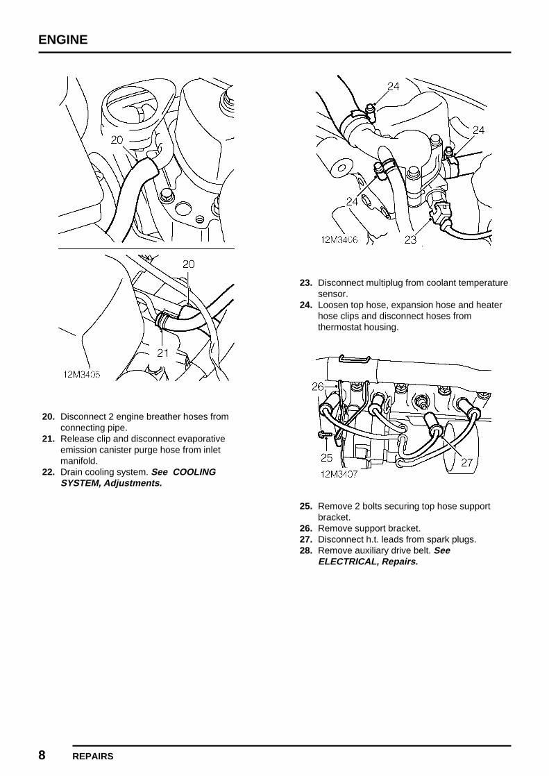
ENGINE
8 REPAIRS
20. Disconnect 2 engine breather hoses fromconnecting pipe.
21. Release clip and disconnect evaporativeemission canister purge hose from inletmanifold.
22. Drain cooling system. See COOLINGSYSTEM, Adjustments.
23. Disconnect multiplug from coolant temperaturesensor.
24. Loosen top hose, expansion hose and heaterhose clips and disconnect hoses fromthermostat housing.
25. Remove 2 bolts securing top hose supportbracket.
26. Remove support bracket.27. Disconnect h.t. leads from spark plugs.28. Remove auxiliary drive belt. See
ELECTRICAL, Repairs.

ENGINE
REPAIRS 9
29. Loosen 2 lower bolts securing alternator toengine.
30. Remove upper nut and bolt securing alternatorto mounting bracket.
31. Move alternator away from bracket on cylinderhead.
32. Remove rocker shaft assembly. See thissection.
33. Remove 5 remaining cylinder head nuts34. Remove push rods and retain them in original
order.35. Remove cylinder head assembly.36. Remove and discard cylinder head gasket.
Refit
1. Clean joint surfaces of cylinder head andcylinder block and ensure rocker shaft oil feeddrilling is clear.
2. Clean mating faces exhaust manifold andexhaust front pipe.
3. Fit new cylinder head gasket dry and ensurethat marks "TOP" and "FRONT" are correctlypositioned.
4. Clean and lubricate push rods, and fit them inoriginal positions.
5. Fit rocker shaft assembly. See this section.

ENGINE
10 REPAIRS
6. Fit cylinder head nuts and tighten progressivelyin order shown to 34 Nm initially. Finally,tighten in order shown to 68 Nm.
7. Tighten rocker shaft bracket nuts to 25 Nm.8. Align alternator to bracket on cylinder head, fit
and tighten upper nut and bolt to 25 Nm.9. Tighten lower bolts securing alternator to
engine to 25 Nm.10. Fit auxiliary drive belt. See ELECTRICAL,
Repairs.11. Connect h.t. leads to spark plugs.12. Fit top hose support bracket to coil bracket and
secure with bolts.13. Connect top hose, expansion tank hose and
heater hoses to thermostat housing and tightenhose clips.
14. Connect evaporative emission canister purgehose to inlet manifold and secure with clip.
15. Connect engine breather hoses to connectingpipe.
16. Clean ends of fuel pipes.17. Connect fuel feed hose to fuel pipe.18. Connect fuel return hose to pipe.19. Connect HO2S multiplug to harness.20. Secure HO2S lead to harness with cable tie.21. Secure harness clip to rear of air cleaner
bracket.22. Connect multiplug to coolant temperature
sensor.23. Connect multiplug to IAT sensor.24. Connect multiplugs to fuel injectors.25. Connect multiplug to IACV.26. Connect multiplug to TP sensor.27. Connect multiplug to MAP sensor.28. Connect brake servo vacuum pipe to inlet
manifold.29. Fit strap securing engine harness to heater
hose.30. Secure engine harness clip to air cleaner
bracket.31. Connect throttle cable to throttle cam and
locate adjusting nut to abutment bracket.32. Adjust throttle cable. See ENGINE
MANAGEMENT SYSTEM - MEMS,Adjustments.
33. Fit front pipe to manifold gasket. SeeMANIFOLD & EXHAUST SYSTEMS, Repairs.
34. Fit bonnet See BODY, Exterior fittings.35. Connect battery earth lead.

ENGINE
REPAIRS 11
ROCKER COVER GASKET
Service repair no - 12.29.40.
Remove
1. Disconnect battery earth lead.
2. Remove 2 bolts securing rocker cover tocylinder head.
3. Collect sealing rubbers and retainers.4. Remove rocker cover and gasket.
Refit
1. Clean mating face of rocker cover and cylinderhead.
2. Clean retainers and sealing rubbers.3. Position gasket and cover. Fit sealing rubbers
and retainers.4. Fit bolts securing rocker cover to cylinder head
and tighten to 5 Nm.5. Connect battery earth lead.
ROCKER SHAFT ASSEMBLY
Service repair no - 12.29.54
Remove
1. Drain cooling system. See COOLINGSYSTEM, Adjustments.
2. Remove rocker cover. See this section.
3. Loosen in the sequence shown the 13 nutssecuring rocker shaft brackets and cylinderhead then remove the 8 nuts securing therocker shaft brackets only.
4. Remove rocker shaft lock plate.5. Remove the rocker shaft assembly.

ENGINE
12 REPAIRS
Refit
1. Ensure rocker shaft is clean and oil passage isclear.
2. Fit rocker shaft assembly locating the rockerscrews in the push rods.
3. Fit rocker shaft lock plate.
4. Working in sequence shown, tighten thecylinder head nuts to 34 Nm then to 68 Nm.
5. Tighten rocker shaft nuts to 25 Nm.6. Adjust valve to rocker clearances. See
Adjustments.7. Fit rocker cover. See this section.8. Fill cooling system. See COOLING SYSTEM,
Adjustments.

ENGINE
REPAIRS 13
VALVE
Service repair no - 12.29.59
Remove
1. Remove cylinder head. See this section.2. Remove bolt securing engine breather pipe to
cylinder head.3. Remove 6 nuts securing inlet and exhaust
manifolds to cylinder head.4. Remove inlet and exhaust manifolds.5. Remove and discard manifold gasket.6. Remove inlet manifold locating rings.7. Remove 4 spark plugs.
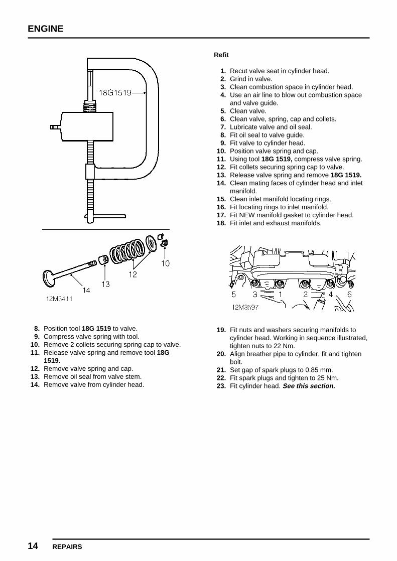
ENGINE
14 REPAIRS
8. Position tool 18G 1519 to valve.9. Compress valve spring with tool.
10. Remove 2 collets securing spring cap to valve.11. Release valve spring and remove tool 18G
1519.12. Remove valve spring and cap.13. Remove oil seal from valve stem.14. Remove valve from cylinder head.
Refit
1. Recut valve seat in cylinder head.2. Grind in valve.3. Clean combustion space in cylinder head.4. Use an air line to blow out combustion space
and valve guide.5. Clean valve.6. Clean valve, spring, cap and collets.7. Lubricate valve and oil seal.8. Fit oil seal to valve guide.9. Fit valve to cylinder head.
10. Position valve spring and cap.11. Using tool 18G 1519, compress valve spring.12. Fit collets securing spring cap to valve.13. Release valve spring and remove 18G 1519.14. Clean mating faces of cylinder head and inlet
manifold.15. Clean inlet manifold locating rings.16. Fit locating rings to inlet manifold.17. Fit NEW manifold gasket to cylinder head.18. Fit inlet and exhaust manifolds.
19. Fit nuts and washers securing manifolds tocylinder head. Working in sequence illustrated,tighten nuts to 22 Nm.
20. Align breather pipe to cylinder, fit and tightenbolt.
21. Set gap of spark plugs to 0.85 mm.22. Fit spark plugs and tighten to 25 Nm.23. Fit cylinder head. See this section.

ENGINE
REPAIRS 15
ENGINE AND GEARBOX
Service repair no - 12.37.01/99
Remove
1. Disconnect battery earth lead.2. Raise front of vehicle.
WARNING: Support on safety stands.
3. Drain engine oil. SeeMAINTENANCEMaintenance.
4. Fit new sealing washer to drain plug.5. Fit drain plug and tighten to 34 Nm.6. Remove bonnet. See BODY, Exterior
fittings.7. Remove radiator. See COOLING SYSTEM,
Repairs.8. Remove engine steady bar - upper. See this
section.9. Remove ECM. See ENGINE MANAGEMENT
SYSTEM - MEMS, Repairs.10. Remove servo and mounting bracket
assembly. See BRAKES, Repairs.11. Remove starter motor. See ELECTRICAL,
Repairs.12. Remove horn. See ELECTRICAL, Repairs.
13. Remove cover from engine compartment fusebox.
14. Remove fusible link.15. Release retaining tag and disconnect engine
harness lead from fuse box.16. Release engine compartment fuse box from
ECM mounting bracket.

ENGINE
16 REPAIRS
17. Release clip securing main harness to ECMmounting bracket.
18. Remove bolt securing ECM mounting bracketto body.
19. Release ECM mounting bracket from body andremove.
20. Remove bolt securing earth leads to body.
21. Disconnect Lucar from bonnet switch.
22. Disconnect fresh air intake hose from ductunder RH front wing.
23. Release and remove fresh air intake duct frominner wing.
24. Loosen unions and disconnect brake pipesfrom pressure reducing valve.
CAUTION: Plug the connections.

ENGINE
REPAIRS 17
25. Disconnect multiplug from ECT sensor.26. Release clip securing ECT sensor harness to
mounting bracket.27. Loosen clip and disconnect expansion tank
hose from thermostat housing.28. Loosen clip and remove radiator top hose from
thermostat housing.
29. Remove 2 nuts securing coolant expansiontank mounting bracket to body.
30. Release mounting bracket from body.
31. Release clip and disconnect coolant feed hosefrom expansion tank.
32. Remove coolant expansion tank and mountingbracket.
33. Remove 2 bolts securing clutch slave cylinderto bracket on flywheel housing.
34. Withdraw slave cylinder from push rod andposition aside.
35. Position absorbent cloth around fuel line quickfit connectors.

ENGINE
18 REPAIRS
36. Release quick fit connector and disconnect fuelreturn hose from fuel pipe.
37. Release quick fit connector and disconnect fuelfeed hose from fuel pipe.
38. Release clips and disconnect heater hoses.
39. Release clip and disconnect purge hose frompipe.
40. Release throttle cable adjustment nut fromabutment bracket.
41. Disconnect inner cable from throttle cam andposition aside.

ENGINE
REPAIRS 19
42. Disconnect multiplug from evaporativeemission canister purge valve.
43. Disconnect engine harness multiplug frommain harness.
44. Release engine harness multiplug from bracketon body.
45. Remove exhaust front pipe. See MANIFOLD& EXHAUST SYSTEMS, Repairs.
46. Select reverse gear.
47. Using a suitable punch, drive out roll pinsecuring selector rod to selector shaft.
48. Release selector rod from shaft.49. Select neutral.50. Remove nut and bolt securing gear change
steady bar to gearbox.
51. Using tool 18G 1240 release drive shafts fromdifferential housing.
52. Remove both front road wheels.53. Raise one side of front suspension using a jack
positioned beneath lower suspension arm.
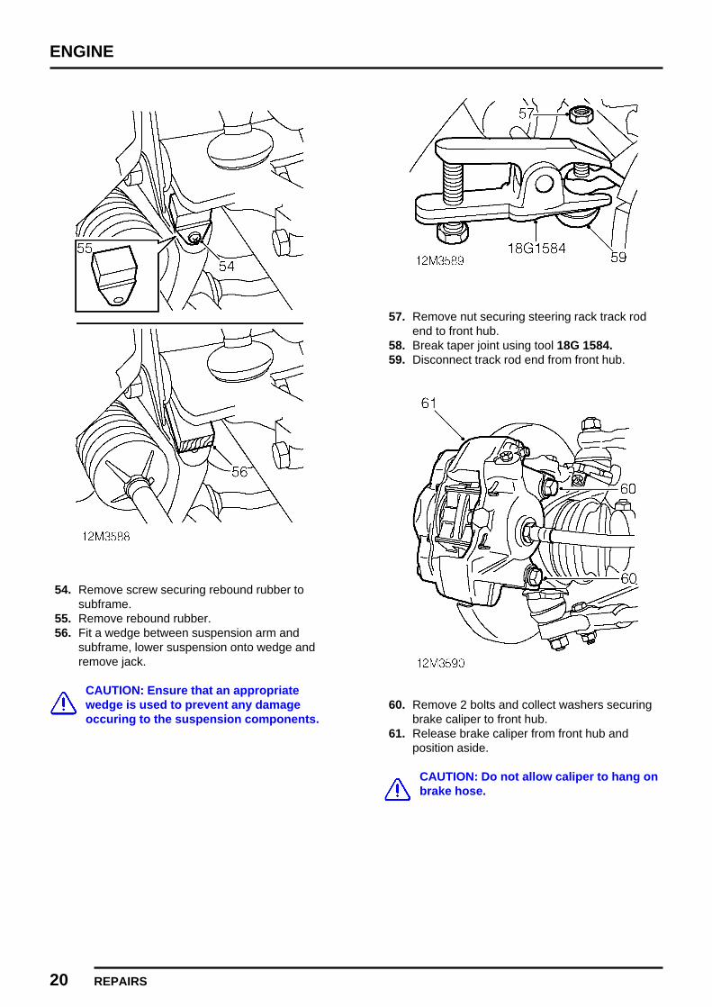
ENGINE
20 REPAIRS
54. Remove screw securing rebound rubber tosubframe.
55. Remove rebound rubber.56. Fit a wedge between suspension arm and
subframe, lower suspension onto wedge andremove jack.
CAUTION: Ensure that an appropriatewedge is used to prevent any damageoccuring to the suspension components.
57. Remove nut securing steering rack track rodend to front hub.
58. Break taper joint using tool 18G 1584.59. Disconnect track rod end from front hub.
60. Remove 2 bolts and collect washers securingbrake caliper to front hub.
61. Release brake caliper from front hub andposition aside.
CAUTION: Do not allow caliper to hang onbrake hose.

ENGINE
REPAIRS 21
62. Remove nut and washer securing front hubupper ball joint to suspension arm.
63. Break taper joint using tool 18G 1584.
CAUTION: Be careful not to damage therubber boot on ball joint.
64. Support front hub on stand.65. Repeat procedure to release suspension arm
from front hub on other side.66. Withdraw drive shafts from differential housing.67. Fit suitable lifting brackets to engine.68. Connect hoist to engine lifting brackets and
raise hoist to take weight of engine withoutexerting load on engine mounting bolts.
69. Remove 2 nuts and bolts securing engine LHmounting to subframe, collect washers.
70. Remove 2 nuts and bolts securing engine RHmounting to subframe, collect washers.
71. Raise engine to gain access to speedometercable union.

ENGINE
22 REPAIRS
72. Loosen union and disconnect speedometercable from gearbox.
73. Using assistance, raise engine and manoeuvrefrom vehicle.
Refit
1. Using assistance, raise engine and manoeuvreinto position in vehicle.
2. Connect speedometer cable to gearbox andtighten union.
3. Align engine RH mounting to subframe. Fitbolts, washers and nuts securing enginemounting to subframe.
4. Align engine LH mounting to subframe. Fitbolts, washers and nuts securing enginemounting to subframe.
5. Disconnect hoist from engine lifting bracketsand remove lifting brackets.
6. Tighten nuts and bolts securing enginemountings to subframe to 22 Nm.
7. Thoroughly clean splines of drive shaft.8. Fit new circlip to drive shaft.9. Engage drive shaft in differential and push fully
home.
CAUTION: Pull drive shaft to ensure circlipis fully engaged and retains shaft.
10. Clean front hub upper ball joint and suspensionarm.
11. Locate suspension arm on front hub upper balljoint.
12. Fit nut and washer securing suspension arm toball joint and tighten nut to 52 Nm.
13. Clean front brake disc.14. Fit brake caliper to front hub.15. Fit 2 bolts and washer securing brake caliper to
front hub and tighten to 52 Nm.16. Connect steering rack track rod end to front
hub, fit nut and tighten to 30 Nm.17. Position jack beneath lower suspension arm
and raise front suspension.18. Remove wedge between suspension arm and
subframe.19. Position rebound rubber and secure with
screw.20. Remove jack from beneath suspension arm.21. Repeat procedure to connect suspension arm
to front hub on other side.22. Fit both front road wheels.

ENGINE
REPAIRS 23
23. Align gear change steady bar to gearbox andsecure with nut and bolt.
24. Connect selector rod to selector shaft and alignholes.
25. Fit new roll pin securing selector rod to shaft.26. Fit exhaust front pipe. See MANIFOLD &
EXHAUST SYSTEMS, Repairs.27. Connect engine harness multiplug to main
harness and secure to bracket on body.28. Connect multiplug to evaporative emission
canister purge valve.29. Ensure throttle cable is correctly routed and
connect inner cable to throttle cam.30. Secure throttle cable adjusting nut to abutment
bracket.31. Connect purge hose to pipe and secure with
clip.32. Connect heater hoses and secure with clips.33. Clean ends of fuel return and fuel feed pipes.34. Identify and connect fuel return hose to fuel
pipe.35. Identify and connect fuel feed hose to fuel pipe.
CAUTION: Ensure hoses are correctlylocated on fuel pipes.
36. Fit clutch slave cylinder onto push rod.37. Align clutch slave cylinder to mounting bracket
on flywheel housing, fit bolts and tighten to 37Nm.
38. Position coolant expansion tank and mountingbracket to body.
39. Connect coolant feed hose to expansion tankand secure with clip.
40. Fit 2 nuts securing coolant expansion tankmounting bracket to body and tighten to 10Nm.
41. Connect expansion tank hose to thermostathousing and tighten clip.
42. Connect radiator top hose to thermostathousing and tighten clip.
43. Secure ECT sensor harness clip to expansiontank mounting bracket.
44. Connect multiplug to ECT sensor.45. Remove plugs from brake pressure reducing
valve.46. Clean brake pipe unions.47. Connect brake pipes to pressure reducing
valve and tighten unions to 14 Nm.48. Position earth leads to body, fit bolt and tighten
to 10 Nm.49. Connect Lucar to bonnet switch.50. Fit fresh air intake duct to inner wing.51. Connect fresh air intake hose to duct beneath
wing.52. Locate ECM mounting bracket on body, fit bolt
and tighten to 10 Nm.53. Secure clip on main harness to ECM mounting
bracket.54. Secure engine compartment fuse box to ECM
mounting bracket.55. Connect engine harness lead to engine
compartment fuse box.56. Fit fusible link.57. Fit cover to engine compartment fuse box.58. Fit horn. See ELECTRICAL, Repairs.59. Fit starter motor. See ELECTRICAL, Repairs.60. Fit servo and mounting bracket assembly. See
BRAKES, Repairs.61. Fit ECM. See ENGINE MANAGEMENT
SYSTEM - MEMS, Repairs.62. Fit engine steady bar - upper. See this
section.63. Fit radiator. See COOLING SYSTEM,
Repairs.64. Remove stand(s) and lower vehicle.65. Connect battery earth lead.66. Refill engine with oil. See
MAINTENANCEMaintenance.67. Adjust throttle cable. See ENGINE
MANAGEMENT SYSTEM - MEMS,Adjustments.
68. Fit bonnet. See BODY, Exterior fittings.

ENGINE
24 REPAIRS
ENGINE LH MOUNTING
Service repair no - 12.45.11.
Remove
1. Raise front of vehicle.
WARNING: Support on safety stands.
2. Disconnect battery earth lead.
3. Remove bolt securing radiator bottom hose toengine mounting.
4. Position jack to support engine.
CAUTION: Use a block of wood or hardrubber pad between jack and engine.
5. Take weight off engine mounting.6. Remove 2 bolts securing engine mounting
bracket to gearbox.7. Remove 2 bolts securing engine mounting to
subframe.
8. Remove engine mounting and bracket.9. Position bracket in a vice, remove 2 bolts
securing mounting to bracket and removemounting.
Refit
1. Position mounting to bracket, fit bolts andtighten to 22 Nm.
2. Remove bracket from vice, fit mounting tosubframe and tighten bolts to 22 Nm.
3. Lower engine and align to mounting bracket fitand tighten bolts to 25 Nm.
4. Remove jack5. Fit bolt securing radiator bottom hose to engine
mounting.6. Remove stand(s) and lower vehicle.7. Connect battery earth lead.

ENGINE
REPAIRS 25
ENGINE RH MOUNTING
Service repair no - 12.45.12
Remove
1. Remove flywheel housing cover. SeeCLUTCH, Repairs.
2. Remove 3 bolts securing engine mounting toflywheel housing cover, collect washers.
3. Remove engine mounting.
Refit
1. Clean mating face of flywheel housing coverand engine mounting.
2. Position engine mounting to cover, fit bolts andwashers and tighten to 18 Nm.
3. Fit flywheel housing cover. See CLUTCH,Repairs.
ENGINE STEADY BAR - UPPER
Service repair no - 12.45.16
Remove
1. Remove air cleaner. See ENGINEMANAGEMENT SYSTEM - MEMS, Repairs.
2. Remove nut and bolt securing steady bar tobody.
3. Release earth strap from body.4. Remove bolt securing steady bar to engine and
collect washers.5. Remove bolt securing engine steady bar
bracket to engine and remove bracket.6. Remove engine steady bar and earth strap.

ENGINE
26 REPAIRS
Do not carry out further dismantling ifcomponent is removed for access only.
7. Remove spacers from steady bar bushes.8. Remove bushes from steady bar.9. Clean engine steady bar.
10. Fit bushes to steady bar.11. Fit spacers to steady bar bushes.
Refit
1. Fit steady bar to bracket on body and align toengine.
2. Fit washer between steady bar and engine.3. Fit steady bar bracket to engine, fit bolt and
tighten to 22 Nm.4. Fit earth strap to bolt, fit bolt securing steady
bar to engine and tighten to 22 Nm.5. Fit bolt securing steady bar to body and
connect earth strap.6. Fit nut and tighten bolt to 22 Nm.7. Fit air cleaner. See ENGINE MANAGEMENT
SYSTEM - MEMS, Repairs.
ENGINE STEADY BAR - LOWER
Service repair no - 12.45.17
Remove
1. Raise front of vehicle.
WARNING: Support on safety stands.
2. Remove nut and bolt securing steady bar tobracket on flywheel housing.
3. Collect steady bar washers.4. Remove nut and bolt securing steady bar to
subframe.5. Remove engine steady bar and collect
washers.

ENGINE
REPAIRS 27
Do not carry out further dismantling ifcomponent is removed for access only.
6. Remove spacers from steady bar bushes.7. Remove bushes from steady bar.8. Clean engine steady bar.9. Fit bushes to steady bar.
10. Fit spacers to steady bar bushes.
Refit
1. Position steady bar to mounting on subframe.2. Fit washer between steady bar and subframe.3. Fit nut and bolt securing steady bar to
subframe and tighten to 40 Nm.4. Align steady bar to bracket on flywheel housing
and position washers.5. Fit nut and bolt securing steady bar to flywheel
housing bracket and tighten to 40 Nm.6. Remove stand(s) and lower vehicle.
FLYWHEEL HOUSING OIL SEAL
Service repair no - 12.53.02
Remove
1. Remove clutch assembly. See CLUTCH,Repairs.
2. Remove dust shield from primary gear.3. Remove ’C’ washer securing primary gear to
crankshaft.4. Remove backing ring from crankshaft.

ENGINE
28 REPAIRS
5. Position seal removing tool 18G 1068B andscrew centre bolt of tool into end of crankshaft.
6. Pull the primary gear outwards as far aspossible by hand.
7. Locate collets of tool 18G 1068B into thegroove on the primary gear.
8. Loosen wing nut on tool to withdraw primarygear and oil seal out of housing.
9. Undo wing nut on tool and remove tool.10. Collect collets.11. Remove primary gear and oil seal.12. Remove and discard oil seal from primary
gear.
Refit
1. Clean primary gear, crankshaft bearingsurface, backing ring and ’C’ washer.
2. Clean oil seal housing and dust shield.3. Lubricate inner face of new oil seal with oil and
apply grease to outer face.
4. Fit protective sleeve 18G 1043 to primary gear.5. Lubricate protective sleeve with oil.6. Position new oil seal on primary gear.7. Remove protective sleeve from primary gear.8. Locate primary gear onto crankshaft until the
gear teeth are just starting to mesh with thoseof the idler gear.
CAUTION: DO NOT fully engage primarygear with idler gear or the seal will becomedisplaced.
9. Position tool 18G 1068 over crankshaft.10. Tighten wing nut of tool 18G 1068 to press oil
seal into flywheel housing.
NOTE: The seal is correctly fitted when thebase of the tool contacts the lip of thehousing bore.
11. Loosen wing nut on tool 18G 1068 andremove tool.
12. Position backing ring on crankshaft.13. Fit ’C’ washer to crankshaft.14. Fit dust shield onto primary gear with its
stepped face marked ’FLYWHEEL SIDE’facing away from the engine.
15. Fit clutch assembly. See CLUTCH, Repairs.

ENGINE
REPAIRS 29
FLYWHEEL HOUSING GASKET
Service repair no - 12.53.04
Remove
1. Drain engine/gearbox oil. SeeMAINTENANCEMaintenance.
2. Remove brake master cylinder. See BRAKES,Repairs.
3. Remove clutch assembly and release bearing.See CLUTCH, Repairs.
4. Loosen unions and disconnect brake pipesfrom pressure reducing valve.
CAUTION: Plug the connections.
5. Fit protective sleeve 18G 1043 to primary gearsplines.
6. Remove nut and bolt securing steady bar tobody.
7. Release earth strap from body.8. Remove bolt securing steady bar to engine and
collect washers.9. Remove bolt securing engine steady bar
bracket to engine and remove bracket.10. Remove engine steady bar and earth strap.

ENGINE
30 REPAIRS
11. Remove 3 bolts securing top of flywheelhousing to engine.
12. Remove 4 bolts securing bottom of flywheelhousing to gearbox and collect bracket.
13. Remove 8 inner bolts securing flywheelhousing to engine and gearbox.
NOTE: The 3 upper bolts securing thecentre of the flywheel housing to engineand gearbox have a different thread than
the other 5.
14. Raise engine on jack.
15. Release flywheel housing from 2 locatingdowels on engine.
16. Manoeuvre flywheel housing from enginecompartment and remove.
17. Remove locating dowels from engine andgearbox.

ENGINE
REPAIRS 31REVISED: 12/96
18. Using a suitable drift, remove primary gear oilseal from flywheel housing.
NOTE: The oil seal can be renewedwithout removing the flywheel housing.Refer to Flywheel housing oil seal. See
this section.
Refit
1. Remove all traces of gasket material frommating faces of flywheel housing, engine andgearbox.
2. Clean flywheel housing locating dowels.3. Fit locating dowels to engine and gearbox.4. Position flywheel housing on a flat surface and
support underside of housing with a block.5. Clean oil seal aperture in flywheel housing.6. Lubricate NEW flywheel housing oil seal.
7. Position oil seal to flywheel housing and usingtools 18G 134 and 18G 134BC drift oil sealinto place.
8. Fit NEW gasket to engine and gearbox.9. Ensure protective sleeve is fitted to primary
gear splines, manoeuvre flywheel housing intoposition and locate on dowels.
10. Clean Loctite from threads of flywheel housingbolts with a wire brush.
11. Apply Loctite 242 to first 3 threads of each bolt.12. Fit 8 inner bolts securing flywheel housing to
engine and gearbox and tighten to 25 Nm.
NOTE: Ensure 3 bolts with the finer threadare fitted at the top.

ENGINE
32 REPAIRS
13. Position bracket to housing, fit lower boltssecuring housing to gearbox and tighten to 25Nm.
14. Fit upper bolts securing housing to engine andtighten to 25 Nm.
15. Fit steady bar to bracket on body and align toengine.
16. Fit washer between steady bar and engine.17. Fit steady bar bracket to engine, fit bolt and
tighten to 22 Nm.18. Fit earth strap to bolt, fit bolt securing steady
bar to engine and tighten to 22 Nm.19. Fit bolt securing steady bar to body and
connect earth strap.20. Fit nut and tighten bolt to 22 Nm.21. Remove protective sleeve 18G 1043 from
primary gear splines.22. Remove plugs from brake pressure reducing
valve.23. Clean brake pipe unions.24. Connect brake pipes to pressure reducing
valve and tighten unions to 14 Nm.25. Fit clutch assembly and release bearing. See
CLUTCH, Repairs.26. Fit brake master cylinder. See BRAKES,
Repairs.27. Refill engine/gearbox with oil. See
MAINTENANCEMaintenance.
FLYWHEEL
Service repair no - 12.53.07
Remove
1. Remove clutch assembly and release bearing.See CLUTCH, Repairs.

ENGINE
REPAIRS 33
OIL FILTER
Service repair no - 12.60.04
Remove
1. Release radiator top hose from clip on ignitioncoil mounting bracket.
2. Clean area around filter head and place acontainer beneath engine.
3. Unscrew and discard filter.
Refit
1. Clean mating face of filter head.2. Lubricate sealing ring of new filter with clean
engine oil.3. Fit new filter and tighten by hand until it seats
then tighten a further half turn.4. Secure radiator top hose to clip on ignition coil
mounting bracket.5. Top up engine with oil to specification 10w/40
until level is correct.6. Start and run engine and check for leaks.7. Stop engine, wait a few minutes, then check oil
level. Top up if necessary.

ENGINE
34 REPAIRS REVISED: 12/96
OIL PUMP
Service repair no - 12.60.26
Remove
1. Remove flywheel housing gasket. See thissection.
2. Remove 2 bolts securing oil pump to engine.3. Remove pump and discard gasket.
Refit
1. Clean mating faces of oil pump and cylinderblock.
2. Prime oil pump with clean engine oil3. Rotate pump to align drive and fit pump with a
new gasket.4. Fit bolts and tighten to 11 Nm.5. Fit flywheel housing gasket. See this section.
ENGINE TO GEARBOX GASKET
Service repair no - 12.60.38
Remove
1. Remove engine and gearbox from vehicle. Seethis section.
2. Remove 2 bolts securing starter motor toflywheel housing.
3. Remove starter motor.
4. Remove 3 bolts securing clutch slave cylindermounting bracket to flywheel housing.
5. Remove slave cylinder mounting bracket andcollect spacer.
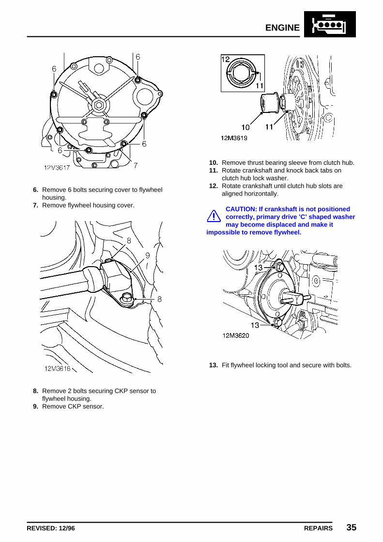
ENGINE
REPAIRS 35REVISED: 12/96
6. Remove 6 bolts securing cover to flywheelhousing.
7. Remove flywheel housing cover.
8. Remove 2 bolts securing CKP sensor toflywheel housing.
9. Remove CKP sensor.
10. Remove thrust bearing sleeve from clutch hub.11. Rotate crankshaft and knock back tabs on
clutch hub lock washer.12. Rotate crankshaft until clutch hub slots are
aligned horizontally.
CAUTION: If crankshaft is not positionedcorrectly, primary drive ’C’ shaped washermay become displaced and make it
impossible to remove flywheel.
13. Fit flywheel locking tool and secure with bolts.

ENGINE
36 REPAIRS REVISED: 12/96
14. Using tool 18G 1303, remove flywheelretaining bolt.
15. Remove key plate from crankshaft.
16. Fit thrust button of tool 18G 1381 to crankshaft.17. Loosen centre bolt of tool 18G 1381 and
position to flywheel.18. Fit and tighten bolts securing tool 18G 1381 to
flywheel19. Tighten centre bolt of tool to release flywheel
from crankshaft taper.20. Remove tool 18G 1381 from flywheel.21. Remove flywheel and clutch assembly.22. Remove oil seal dust shield from primary gear.
23. Fit protective sleeve 18G 1043 to primary gearsplines.
24. Remove 3 bolts securing top of flywheelhousing to engine.
25. Remove 4 bolts securing bottom of flywheelhousing to gearbox and collect bracket.
26. Remove 8 inner bolts securing flywheelhousing to engine and gearbox.
NOTE: The 3 upper bolts securing thecentre of the flywheel housing to engineand gearbox have a different thread than
the other 5.
27. Release flywheel housing from 2 locatingdowels on engine and remove housing.

ENGINE
REPAIRS 37REVISED: 12/96
28. Using a suitable drift, remove primary gear oilseal from flywheel housing.
29. Remove nut and bolt securing gearbox toengine.
30. Remove 11 bolts and 2 nuts securing gearboxto engine.
31. Take weight of engine on lifting chains andrelease gearbox from engine.
32. Remove and discard gaskets.33. Remove and discard main bearing cap oil seal.34. Remove and discard ’O’ ring.

ENGINE
38 REPAIRS REVISED: 12/96
Refit
1. Clean all traces of gasket and sealing materialsfrom engine and gearbox mating faces.
2. Clean locating dowels.3. Lubricate with clean engine oil and fit new ’O’
ring and main bearing cap oil seal to gearbox.4. Fit gaskets to face of gearbox.5. Move primary drive gear to end of crankshaft.6. Lower engine onto gearbox.7. Fit nuts and bolts securing gearbox to engine
and tighten to 8 Nm.8. Fit nut and bolt securing engine to gearbox and
tighten to 8 Nm.9. Position primary drive gear into mesh.
10. Remove all traces of gasket material frommating face of flywheel housing, engine andgearbox.
11. Clean flywheel housing locating dowels.12. Position flywheel housing on a flat surface and
support underside adjacent to seal aperture.13. Clean oil seal aperture in flywheel housing.14. Lubricate new flywheel housing oil seal.
15. Position oil seal to flywheel housing and usingtools 18G 134 and 18G 134BC drift oil sealinto place.
16. Fit new gasket to engine and gearbox.
17. Ensure protective sleeve is fitted to primarygear splines and locate flywheel housing ondowels.
18. Clean Loctite from threads of flywheel housingbolts with a wire brush.
19. Apply Loctite 242 to first 3 threads of each bolt.20. Fit 8 inner bolts securing flywheel housing to
engine and gearbox and tighten to 25 Nm.
NOTE: Ensure 3 bolts with the finer threadare fitted at the top.
21. Position bracket to housing, fit lower boltssecuring housing to gearbox and tighten to 25Nm.
22. Fit upper bolts securing flywheel housing toengine and tighten to 25 Nm.
23. Remove protective sleeve 18G 1043 fromprimary gear splines.
24. Clean crankshaft taper and flywheel.25. Fit dust shield on primary gear.26. Fit flywheel and clutch assembly to crankshaft.27. Fit key plate and NEW flywheel retaining bolt.28. Tighten flywheel retaining bolt to 150 Nm.29. Stake lock washer into slots on clutch hub.30. Remove bolts securing flywheel locking tool.31. Remove flywheel locking tool.32. Clean thrust bearing sleeve.33. Fit thrust bearing sleeve to clutch hub.34. Clean CKP sensor and mating face of flywheel
housing.35. Fit CKP sensor to flywheel housing, fit bolts
and tighten to 6 Nm.36. Clean flywheel housing cover and mating face
of flywheel housing.37. Position cover to flywheel housing, fit bolts and
tighten to 10 Nm.38. Fit clutch slave cylinder mounting bracket and
spacer to flywheel housing.39. Fit 3 bolts securing mounting bracket to
flywheel housing, tighten bolts:M8 bolts to 37 Nm.M5 bolt to 7 Nm.
40. Clean mating face of starter motor and flywheelhousing.
41. Fit starter motor and tighten bolts to 37 Nm.42. Fit engine and gearbox. See this section.

ENGINE
REPAIRS 39ISSUED: 12/96
OIL PRESSURE SWITCH
Service repair no - 12.60.50
Remove
1. Remove ignition coil. See ENGINEMANAGEMENT SYSTEM - MEMS, Repairs.
2. Disconnect multiplug from oil pressure switch.3. Loosen oil pressure switch and remove.
Refit
1. Clean threads of oil pressure switch and holein cylinder block.
2. Apply Loctite 572 to threads of oil pressureswitch.
3. Fit oil pressure switch and tighten to 25 Nm.4. Fit ignition coil. See ENGINE MANAGEMENT
SYSTEM - MEMS, Repairs.
OIL PRESSURE RELIEF VALVE
Service repair no - 12.60.56
Remove
1. Remove starter motor. See ELECTRICAL,Repairs.
2. Remove oil pressure relief valve cap.3. Remove and discard sealing washer from cap.4. Remove spring and relief valve from cylinder
block.

ENGINE
40 REPAIRS ISSUED: 12/96
Refit
1. Clean oil pressure relief valve, spring, cap andseating area of cylinder block.
2. Check the face of the relief valve is not pittedor scored, and that the valve seats correctly incylinder block. Renew if necessary.
3. Measure the length of the spring. If the lengthof the spring is less than 72.5 mm, renewspring.
4. Fit oil pressure relief valve and spring.5. Fit new sealing washer to cap.6. Fit oil pressure relief valve cap and tighten to
60 Nm.7. Fit starter motor. See ELECTRICAL, Repairs.
TIMING GEAR COVER AND OIL SEAL
Service repair no - 12.65.05
Remove
1. Refer to crankshaft front seal for details. Seethis section.
TIMING CHAIN AND GEARS
Service repair no - 12.65.12.
Remove
1. Remove timing gear tensioner. See thissection.
2. Remove oil thrower.3. Bend back the lock washer tab on the
camshaft gear retaining nut.4. Using tool 18G 98 A. unscrew the camshaft
gear retaining nut and remove the lock washer.
5. Rotate the crankshaft until the two timingmarks are aligned.
6. Gently lever off the crankshaft and camshaftgears complete with timing chain.

ENGINE
REPAIRS 41ISSUED: 12/96
Refit
1. Fit the timing gears without the chain.
2. Check the alignment of the gears with astraight edge.
3. Use feeler gauges to determine the thicknessof shim required.DATA: Shim thickness = 0.152 mm.
4. Remove the crankshaft gear and thecrankshaft driving key.
5. Fit the required thickness of shims to obtain thecorrect alignment.
6. Refit the driving key to the crankshaft.7. Clean timing gears,timing chain and crankshaft
and camshaft ends.
8. Position the crankshaft key at TDC and thecamshaft key at 2 o’clock.
9. Fit timing chain and gears and checkalignment.
10. Fit camshaft gear retaining nut and new lockwasher. Tighten nut to 90 Nm.and tap overlock washer.
11. Fit oil thrower with the ’F’ mark facingoutwards.
12. Fit timing chain tensioner. See this section.

ENGINE
42 REPAIRS ISSUED: 12/96
TIMING CHAIN TENSIONER
Service repair no - 12.65.28
Remove
1. Remove timing gear cover. See this section.
2. Remove 2 bolts securing timing chaintensioner to engine.
3. Remove tensioner.
Refit
1. Fit tensioner and tension the chain by applyingfirm pressure on the tensioner.
2. Fit bolts securing tensioner to engine andtighten to 22 Nm.
3. Fit timing gear cover. See this section.
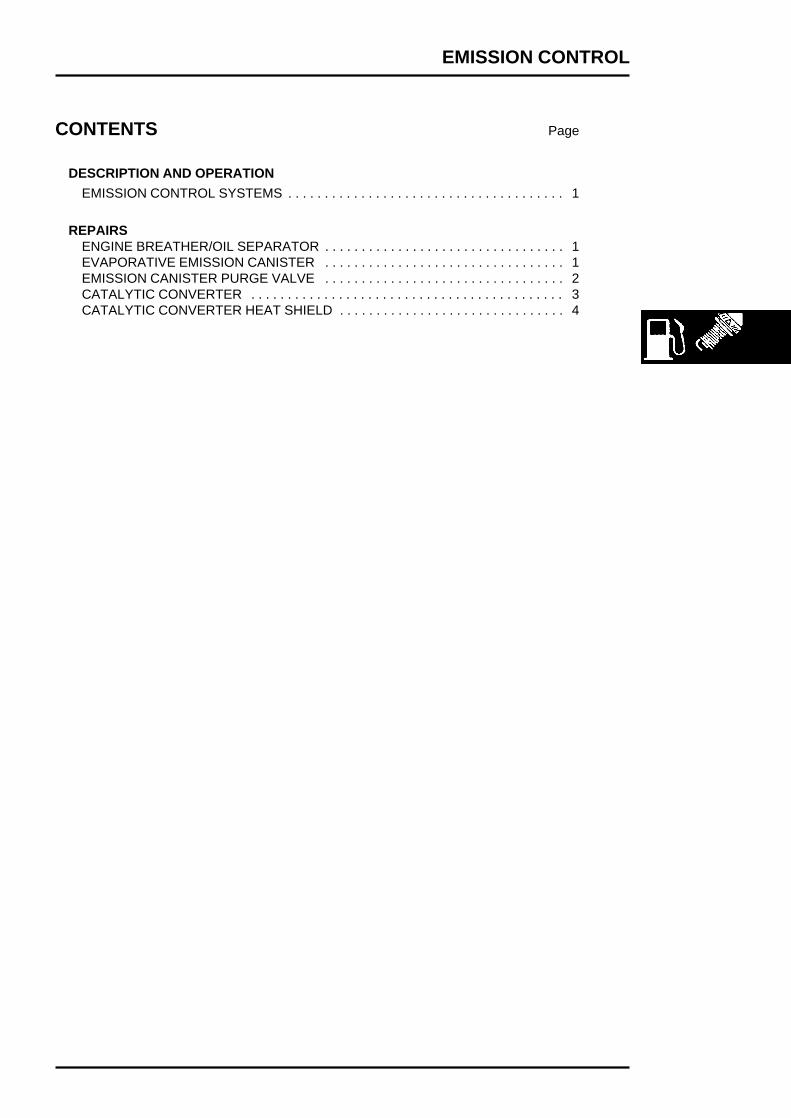
EMISSION CONTROL
CONTENTS Page
DESCRIPTION AND OPERATION
EMISSION CONTROL SYSTEMS 1. . . . . . . . . . . . . . . . . . . . . . . . . . . . . . . . . . . . . .
REPAIRSENGINE BREATHER/OIL SEPARATOR 1. . . . . . . . . . . . . . . . . . . . . . . . . . . . . . . . .EVAPORATIVE EMISSION CANISTER 1. . . . . . . . . . . . . . . . . . . . . . . . . . . . . . . . .EMISSION CANISTER PURGE VALVE 2. . . . . . . . . . . . . . . . . . . . . . . . . . . . . . . . .CATALYTIC CONVERTER 3. . . . . . . . . . . . . . . . . . . . . . . . . . . . . . . . . . . . . . . . . . .CATALYTIC CONVERTER HEAT SHIELD 4. . . . . . . . . . . . . . . . . . . . . . . . . . . . . . .

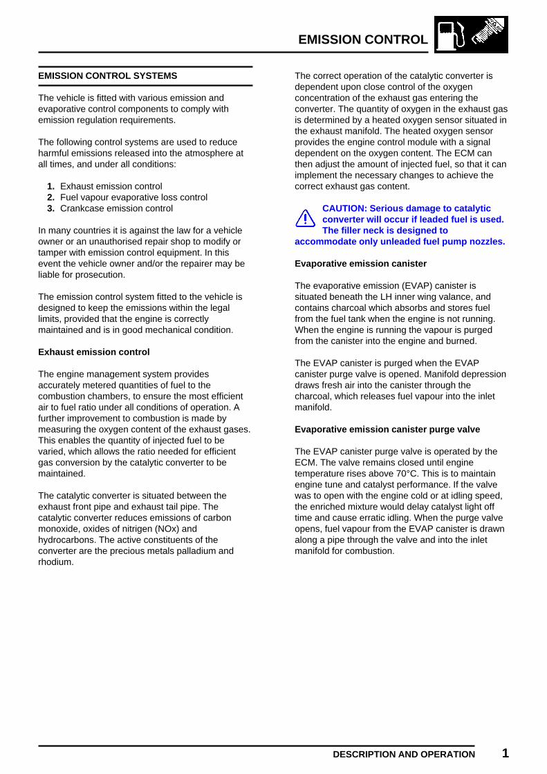
EMISSION CONTROL
DESCRIPTION AND OPERATION 1
EMISSION CONTROL SYSTEMS
The vehicle is fitted with various emission andevaporative control components to comply withemission regulation requirements.
The following control systems are used to reduceharmful emissions released into the atmosphere atall times, and under all conditions:
1. Exhaust emission control2. Fuel vapour evaporative loss control3. Crankcase emission control
In many countries it is against the law for a vehicleowner or an unauthorised repair shop to modify ortamper with emission control equipment. In thisevent the vehicle owner and/or the repairer may beliable for prosecution.
The emission control system fitted to the vehicle isdesigned to keep the emissions within the legallimits, provided that the engine is correctlymaintained and is in good mechanical condition.
Exhaust emission control
The engine management system providesaccurately metered quantities of fuel to thecombustion chambers, to ensure the most efficientair to fuel ratio under all conditions of operation. Afurther improvement to combustion is made bymeasuring the oxygen content of the exhaust gases.This enables the quantity of injected fuel to bevaried, which allows the ratio needed for efficientgas conversion by the catalytic converter to bemaintained.
The catalytic converter is situated between theexhaust front pipe and exhaust tail pipe. Thecatalytic converter reduces emissions of carbonmonoxide, oxides of nitrigen (NOx) andhydrocarbons. The active constituents of theconverter are the precious metals palladium andrhodium.
The correct operation of the catalytic converter isdependent upon close control of the oxygenconcentration of the exhaust gas entering theconverter. The quantity of oxygen in the exhaust gasis determined by a heated oxygen sensor situated inthe exhaust manifold. The heated oxygen sensorprovides the engine control module with a signaldependent on the oxygen content. The ECM canthen adjust the amount of injected fuel, so that it canimplement the necessary changes to achieve thecorrect exhaust gas content.
CAUTION: Serious damage to catalyticconverter will occur if leaded fuel is used.The filler neck is designed to
accommodate only unleaded fuel pump nozzles.
Evaporative emission canister
The evaporative emission (EVAP) canister issituated beneath the LH inner wing valance, andcontains charcoal which absorbs and stores fuelfrom the fuel tank when the engine is not running.When the engine is running the vapour is purgedfrom the canister into the engine and burned.
The EVAP canister is purged when the EVAPcanister purge valve is opened. Manifold depressiondraws fresh air into the canister through thecharcoal, which releases fuel vapour into the inletmanifold.
Evaporative emission canister purge valve
The EVAP canister purge valve is operated by theECM. The valve remains closed until enginetemperature rises above 70°C. This is to maintainengine tune and catalyst performance. If the valvewas to open with the engine cold or at idling speed,the enriched mixture would delay catalyst light offtime and cause erratic idling. When the purge valveopens, fuel vapour from the EVAP canister is drawnalong a pipe through the valve and into the inletmanifold for combustion.

EMISSION CONTROL
2 DESCRIPTION AND OPERATION REVISED: 12/96
Crankcase emission and evaporative losscontrol systems
1. Throttle disc2. Fuel cut-off/two way valves3. Evaporative emission canister4. Evaporative emission canister purge valve5. Fuel filler cap
6. MEMS ECM7. Crankcase breather hose8. Oil breather/separator9. Clean air pipe
10. Restrictor
Crankcase emission control system
To ensure crankcase depression is maintained,clean air is drawn into the system through a pipeconnected to the air cleaner side of the inletmanifold above the throttle disc. The increase inmanifold depression causes air and crankcasegases to pass along pipes through oilbreather/separators on the engine front cover andflywheel housing.
The gases are then drawn through a restrictor intothe inlet manifold below the throttle disc to beconsumed in the combustion chambers. The oil fillercap on the rocker cover also incorporates an internalbreather passage and a filter, to reduce crankcaseemissions.
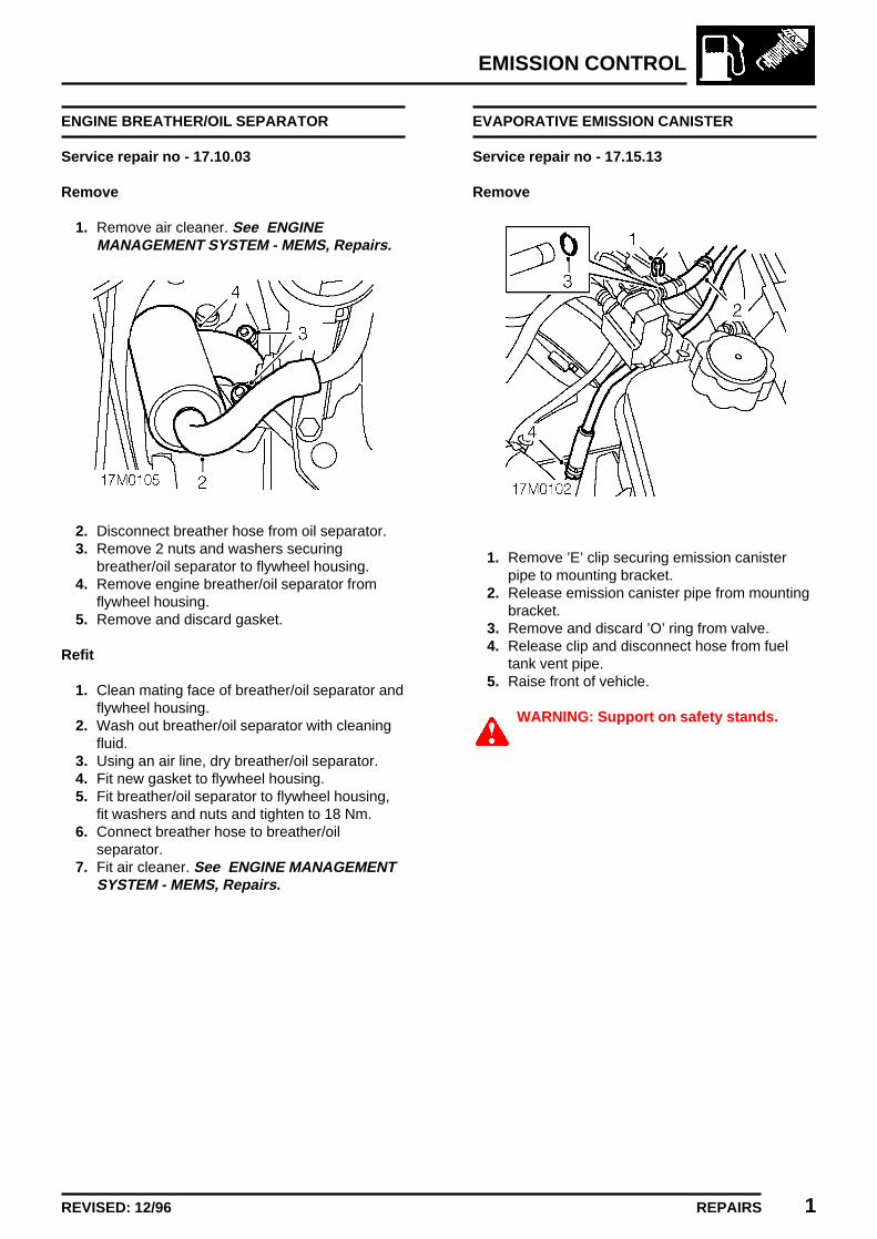
EMISSION CONTROL
REPAIRS 1REVISED: 12/96
ENGINE BREATHER/OIL SEPARATOR
Service repair no - 17.10.03
Remove
1. Remove air cleaner. See ENGINEMANAGEMENT SYSTEM - MEMS, Repairs.
2. Disconnect breather hose from oil separator.3. Remove 2 nuts and washers securing
breather/oil separator to flywheel housing.4. Remove engine breather/oil separator from
flywheel housing.5. Remove and discard gasket.
Refit
1. Clean mating face of breather/oil separator andflywheel housing.
2. Wash out breather/oil separator with cleaningfluid.
3. Using an air line, dry breather/oil separator.4. Fit new gasket to flywheel housing.5. Fit breather/oil separator to flywheel housing,
fit washers and nuts and tighten to 18 Nm.6. Connect breather hose to breather/oil
separator.7. Fit air cleaner. See ENGINE MANAGEMENT
SYSTEM - MEMS, Repairs.
EVAPORATIVE EMISSION CANISTER
Service repair no - 17.15.13
Remove
1. Remove ’E’ clip securing emission canisterpipe to mounting bracket.
2. Release emission canister pipe from mountingbracket.
3. Remove and discard ’O’ ring from valve.4. Release clip and disconnect hose from fuel
tank vent pipe.5. Raise front of vehicle.
WARNING: Support on safety stands.

EMISSION CONTROL
2 REPAIRS REVISED: 12/96
6. Disconnect vent pipe from emission canister.7. Release strap securing emission canister to
mounting bracket beneath wing.8. Release emission canister from mounting
bracket and remove.
Refit
1. Fit emission canister to mounting bracket andsecure with strap.
2. Connect vent hose to emission canister.3. Lubricate new ’O’ ring with silicone grease and
fit to purge valve.4. Connect emission canister pipe to purge valve.5. Secure emission canister pipe to mounting
bracket with ’E’ clip.6. Connect hose to fuel tank vent pipe and secure
with clip.7. Remove stand(s) and lower vehicle.
EMISSION CANISTER PURGE VALVE
Service repair no - 17.15.39
Remove
1. Disconnect multiplug from valve.2. Release clip and disconnect purge hose from
valve.3. Remove ’E’ clip securing emission canister
pipe to mounting bracket.4. Release emission canister pipe from mounting
bracket.5. Slide purge valve from mounting bracket and
remove.6. Remove and discard ’O’ ring from valve.
Refit
1. Lubricate new ’O’ ring with silicone grease andfit to valve.
2. Fit purge valve to mounting bracket.3. Connect emission canister pipe to valve.4. Secure emission canister pipe to mounting
bracket with ’E’ clip.5. Connect purge hose to valve and secure with
clip.6. Connect multiplug to purge valve.

EMISSION CONTROL
REPAIRS 3
CATALYTIC CONVERTER
Service repair no - 17.50.01
Remove
1. Raise front of vehicle.
WARNING: Support on safety stands.
2. Remove 2 nuts securing catalytic converter tofront pipe.
3. Remove 2 nuts securing catalytic converter totail pipe.
4. Disconnect catalytic converter from tail pipeand remove from front pipe.
5. Remove and discard gasket from flange oncatalytic converter.
CAUTION: Catalytic converters aremanufactured from ceramic materialwhich is very fragile, avoid heavy impacts
on converter casing.
Refit
1. Clean mating faces of catalytic converter, frontpipe and tail pipe.
2. Fit new gasket to catalytic converter flange.3. Fit catalytic converter to front pipe and connect
to tail pipe.4. Fit nuts securing front pipe to catalytic
converter and tighten to 45 Nm.5. Fit nuts securing tail pipe to catalytic converter
and tighten evenly to 9 Nm.6. Remove stand(s) and lower vehicle.

EMISSION CONTROL
4 REPAIRS
CATALYTIC CONVERTER HEAT SHIELD
Service repair no - 17.50.05
Remove
1. Remove intermediate pipe heat shield. SeeMANIFOLD & EXHAUST SYSTEMS, Repairs.
2. Remove 2 nuts securing catalytic converterheat shield to body.
3. Release heat shield from studs and slideforward.
4. Manoeuvre heat shield around exhaust pipeand remove.
Refit
1. Manoeuvre heat shield into position and locateon studs.
2. Fit and tighten nuts securing heat shield tobody.
3. Fit intermediate pipe heat shield. SeeMANIFOLD & EXHAUST SYSTEMS, Repairs.

ENGINE MANAGEMENT SYSTEM - MEMS
CONTENTS Page
DESCRIPTION AND OPERATION
ENGINE COMPARTMENT COMPONENT LOCATIONS 1. . . . . . . . . . . . . . . . . . . .ENGINE MANAGEMENT SYSTEM 2. . . . . . . . . . . . . . . . . . . . . . . . . . . . . . . . . . . . .
ADJUSTMENTSTHROTTLE CABLE 1. . . . . . . . . . . . . . . . . . . . . . . . . . . . . . . . . . . . . . . . . . . . . . . . .
REPAIRSTHROTTLE CABLE 1. . . . . . . . . . . . . . . . . . . . . . . . . . . . . . . . . . . . . . . . . . . . . . . . .THROTTLE PEDAL 2. . . . . . . . . . . . . . . . . . . . . . . . . . . . . . . . . . . . . . . . . . . . . . . . .THROTTLE HOUSING 3. . . . . . . . . . . . . . . . . . . . . . . . . . . . . . . . . . . . . . . . . . . . . . .AIR CLEANER 5. . . . . . . . . . . . . . . . . . . . . . . . . . . . . . . . . . . . . . . . . . . . . . . . . . . . .AIR CLEANER ELEMENT 5. . . . . . . . . . . . . . . . . . . . . . . . . . . . . . . . . . . . . . . . . . . .SPARK PLUGS 6. . . . . . . . . . . . . . . . . . . . . . . . . . . . . . . . . . . . . . . . . . . . . . . . . . . .IGNITION COIL 6. . . . . . . . . . . . . . . . . . . . . . . . . . . . . . . . . . . . . . . . . . . . . . . . . . . .ENGINE CONTROL MODULE (ECM) 7. . . . . . . . . . . . . . . . . . . . . . . . . . . . . . . . . . .IDLE AIR CONTROL VALVE (IACV) 8. . . . . . . . . . . . . . . . . . . . . . . . . . . . . . . . . . . .INTAKE AIR TEMPERATURE (IAT) SENSOR 9. . . . . . . . . . . . . . . . . . . . . . . . . . . .ENGINE COOLANT TEMPERATURE (ECT) SENSOR 9. . . . . . . . . . . . . . . . . . . . .CRANKSHAFT POSITION (CKP) SENSOR 10. . . . . . . . . . . . . . . . . . . . . . . . . . . . .THROTTLE POSITION (TP) SENSOR 11. . . . . . . . . . . . . . . . . . . . . . . . . . . . . . . . .MANIFOLD ABSOLUTE PRESSURE (MAP) SENSOR 12. . . . . . . . . . . . . . . . . . . . .ENGINE MANAGEMENT RELAY MODULE 13. . . . . . . . . . . . . . . . . . . . . . . . . . . . .CAMSHAFT POSITION (CMP) SENSOR 13. . . . . . . . . . . . . . . . . . . . . . . . . . . . . . .HEATED OXYGEN SENSOR (HO2S) 14. . . . . . . . . . . . . . . . . . . . . . . . . . . . . . . . . .FUEL RAIL 14. . . . . . . . . . . . . . . . . . . . . . . . . . . . . . . . . . . . . . . . . . . . . . . . . . . . . . .FUEL INJECTORS 16. . . . . . . . . . . . . . . . . . . . . . . . . . . . . . . . . . . . . . . . . . . . . . . . .


ENGINE MANAGEMENT SYSTEM - MEMS
DESCRIPTION AND OPERATION 1
ENGINE COMPARTMENT COMPONENTLOCATIONS
1. Engine Control Module (ECM)2. Relay module3. Idle Air Control Valve (IACV)4. Fuel pressure regulator5. Throttle Position (TP) sensor6. Air cleaner7. Manifold Absolute Pressure (MAP) sensor
8. Intake Air Temperature (IAT) sensor9. Evaporative emission canister purge valve
10. Camshaft Position (CMP) sensor11. Engine Coolant Temperature (ECT) sensor12. Ignition coil13. Heated Oxygen Sensor (HO2S)14. Crankshaft Position (CKP) sensor

ENGINE MANAGEMENT SYSTEM - MEMS
2 DESCRIPTION AND OPERATION REVISED: 12/96
ENGINE MANAGEMENT SYSTEM
The Engine Control Module (ECM) monitors theconditions required for optimum combustion of fuelin the cylinder through sensors located at strategicpoints around the engine. As a result of thesesensor inputs, the engine control module can adjustthe fuel quantity and timing of the fuel beingdelivered to the cylinders.
The main features are as follows:
• A single ECM controls the fuel injection systemand the ignition system. The ECM incorporatesshort circuit protection and can store intermittentfaults on certain inputs. TestBook can interrogatethe ECM for these stored faults.
• The ECM is electronically immobilised whichprevents the engine from being started unless itreceives a coded signal from the anti-theft controlunit.
• In conjunction with the throttle position sensorthe ECM uses the speed/density method of airflow measurement to calculate fuel delivery. Thismethod measures the inlet air temperature andinlet manifold pressure and assumes that theengine is a calibrated vacuum pump, with itscharacteristics stored in the ECM, it can thendetermine the correct amount of fuel to beinjected.
• The vehicle diagnostic connector allows enginetuning or fault diagnosis to be carried out usingTestBook without disconnecting the ECMharness multiplug.
• The ECM harness multiplug incorporatesspecially plated pins to minimise oxidation andgive improved reliability.
• The ECM controls the operation of the radiatorand air conditioning cooling fans, based onsignals received from the engine coolanttemperature sensor.
• If certain system inputs fail, the ECM implementsa back-up facility to enable the system tocontinue functioning, although at a reduced levelof performance.
IGNITION SYSTEM
The ECM determines the optimum ignition timingbased on the signals from the following sensors:
1. Crankshaft position sensor - Engine speed andcrankshaft position
2. Manifold absolute pressure sensor - Engineload
3. Engine coolant temperature sensor - Enginetemperature
4. Throttle position sensor - Throttle pedalreleased
The engine management system uses no centrifugalor vacuum advance. Timing is controlled by theECM which is energised by the main relay, locatedwithin the relay module. Spark distribution isachieved by a direct ignition system which consistsof a twin-ignition coil driven directly from the ECM.

ENGINE MANAGEMENT SYSTEM - MEMS
DESCRIPTION AND OPERATION 3REVISED: 12/96
BASIC IGNITION TIMING
Crankshaft position sensor
The speed and position of the engine is detected bythe crankshaft position (CKP) sensor which is boltedto, and projects through, the engine adaptor plateadjacent to the flywheel.
The CKP sensor is an inductive sensor consisting ofa bracket mounted body containing a coil and apermanent magnet which provides a magnetic field.The CKP sensor is situated so that an air gap existsbetween it and the flywheel. Air gap distance iscritical for correct operation.
The flywheel incorporates a reluctor ring whichconsists of 32 poles spaced at 10° intervals, with 4missing poles at 30°, 60°, 210° and 250°. Themissing poles inform the ECM when to operate thegroups of injectors. When the flywheel rotates, as apole passes the CKP sensor it disturbs the magneticfield inducing a voltage pulse in the coil. This pulseis transmitted to the ECM.
By calculating the number of pulses that occur withina given time, the ECM can determine the enginespeed. This is a primary input necessary to makethe engine run.
Camshaft position sensor
The camshaft position sensor has two functions. Thefirst is to enable the ECM to run a sequential fuellingmode. The second is to measure the actual camperiod, this measurement is achieved using teeth onthe camshaft to indicate when the valve opens andcloses.
If the camshaft position sensor fails when the engineis running, the engine will continue to run normally insequential fuelling mode. If the sensor fails beforethe engine is started, the engine will start but run ata reduced rev limit in comparison to the normal revlimit of 6500 rpm. Camshaft position sensor failurecan be identified using TestBook.

ENGINE MANAGEMENT SYSTEM - MEMS
4 DESCRIPTION AND OPERATION
Manifold absolute pressure sensor
The manifold absolute pressure (MAP) sensor ismounted directly on the inlet manifold. The MAPsensor converts pressure variations within the inletmanifold into graduated electrical signals which canbe read by the ECM. Increases and decreases in themanifold pressure provide the ECM with an accuraterepresentation of the load being placed on theengine allowing the ECM to adjust the quantity offuel being injected and the ignition timing to achieveoptimum fuelling of the engine.
IGNITION TIMING COMPENSATION
Engine coolant temperature sensor
The engine coolant temperature (ECT) sensor is a’thermistor’ (a temperature dependent resistor), i.e.the voltage output varies in proportion totemperature. The ECT sensor is located on top ofthe coolant outlet elbow. The ECM constantlymonitors this signal and uses the information toprovide optimum driveability and emissions byadvancing or retarding the ignition timing.
Idle speed control
With the throttle pedal released and the engine atidle, the ECM uses the fast response of the engineto ignition timing to maintain idle stabilisation.
When loads are placed on or removed from theengine, the ECM responds to changes in enginespeed and in conjunction with adjusting the idle aircontrol valve (IACV), advances or retards theignition timing to maintain a specified idle speed.When load is removed from the engine the IACVreturns to its original position and the ignition timingreturns to the idle setting.
NOTE: Due to the sensitivity of thissystem the ignition timing will beconstantly changing at idle speed.
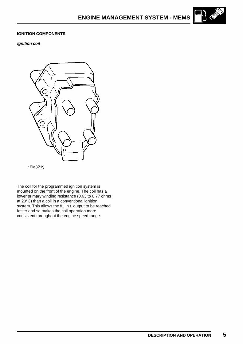
ENGINE MANAGEMENT SYSTEM - MEMS
DESCRIPTION AND OPERATION 5
IGNITION COMPONENTS
Ignition coil
The coil for the programmed ignition system ismounted on the front of the engine. The coil has alower primary winding resistance (0.63 to 0.77 ohmsat 20°C) than a coil in a conventional ignitionsystem. This allows the full h.t. output to be reachedfaster and so makes the coil operation moreconsistent throughout the engine speed range.

ENGINE MANAGEMENT SYSTEM - MEMS
6 DESCRIPTION AND OPERATION
FUEL SYSTEM
Engine Control Module (ECM)
The Modular Engine Management System (MEMS)is controlled by an ECM mounted in the enginecompartment. The ECM is an adaptive unit whichover a period of time learns the load and wearcharacteristics of the engine it controls. The ECMremembers and updates two main enginerequirements when the engine is running at normaloperating temperature:
1. The position of the idle air control (IAC) valverequired to achieve a specified idle speed. Thisis then used as a reference for IAC valvemovement to achieve idle speed under all loadconditions.
2. The fuelling change or offset required toachieve a set oxygen sensor voltage. Thisallows the system to provide the correctfuelling without having to apply excessiveadjustments to the fuelling which can adverselyaffect the emissions and driveability.
NOTE: After fitting a different ECM,TestBook will be required to reprogrammethe ECM with the code from the anti-theft
control unit and to perform a full engine tuneprocedure.
The ECM inputs and outputs are shown in thefollowing table:
INPUTS OUTPUTS
Crankshaft position sensorCamshaft position sensor Purge valveManifold absolute pressure sensor Ignition coilEngine coolant temperature sensor InjectorsIntake air temperature sensor Idle air control valveHeated oxygen sensor ECM Fuel pump relayThrottle position sensor Diagnostic connectorDiagnostic input Heated oxygen sensor relayBattery supply Main relayStarter signal Cooling fansEarth supply Air conditioningAnti-theft control unit

ENGINE MANAGEMENT SYSTEM - MEMS
DESCRIPTION AND OPERATION 7REVISED: 12/96
Intake air temperature sensor
The intake air temperature (IAT) sensor is located inthe side of the inlet manifold. The IAT sensor is ofthe negative temperature coefficient (NTC) type,designed to reduce its resistance with increasingtemperature. The ECM receives a signalproportional to the temperature of the intake air.When used in conjunction with the signal from themanifold absolute pressure sensor the ECM cancalculate the volume of oxygen in the air and adjustthe quantity of fuel being injected to achieveoptimum fuelling of the engine.
Injectors
The two fuel injectors are fitted between thepressurised fuel rail and inlet manifold. Each injectorcomprises a solenoid operated needle valve and aspecially designed nozzle to ensure good fuelatomisation.
The ECM determines when to operate the injectorsbased on the signal it receives from the crankshaftposition sensor.
The ECM provides an earth signal for the period theinjectors are required to be open, the injectorsolenoids are energised and fuel is sprayed into theinlet manifold onto the back of the inlet valves. TheECM carefully meters the amount of fuel injected byadjusting the injector opening period (pulse width).During cranking, when the engine speed is belowapproximately 400 rev/min, the ECM increases theinjector pulse width to aid starting. The amount ofincrease depends upon engine coolant temperature.To prevent flooding, the ECM periodically inhibits theoperation of the injectors.

ENGINE MANAGEMENT SYSTEM - MEMS
8 DESCRIPTION AND OPERATION
Throttle housing
The throttle housing is located between the inletmanifold and air intake hose and is sealed to themanifold by an ’O’ ring. The throttle housingincorporates a throttle disc which is connected to thethrottle pedal via the throttle lever and a cable.
There are two breather pipes connected to thethrottle housing; one either side of the throttle disc.When the engine is running with the throttle discopen, both pipes are subject to manifold depressionand draw crankcase fumes into the manifold. Whenthe throttle disc is closed, only the pipe on the inletmanifold side of the disc is subject to manifolddepression. This pipe incorporates a restrictor toprevent engine oil being drawn into the engine bythe substantially greater manifold depression.
Mounted on the throttle housing are the throttleposition sensor and idle air control valve.
Throttle position sensor
The throttle position (TP) sensor is a potentiometerattached to the throttle housing and is directlycoupled to the throttle disc. The TP sensor isnon-adjustable. Closed throttle is detected by the TPsensor which initiates idle speed control via the idleair control valve.
The ECM supplies the TP sensor with a 5 voltsupply and an earth path. The TP sensor returns asignal proportional to throttle disc position.
Throttle disc movement causes voltage across theTP sensor to vary. The ECM calculates the rate ofchange of the voltage signal in positive(acceleration) or negative (deceleration) directions.From this the ECM can determine the requiredengine speed, rate of acceleration or rate ofdeceleration and apply acceleration enrichment,deceleration fuel metering or over-run fuel cut-off.

ENGINE MANAGEMENT SYSTEM - MEMS
DESCRIPTION AND OPERATION 9
Idle air control valve
The idle air control valve (IACV) is mounted on theinlet manifold and controlled by the ECM. The IACVopens a pintle valve situated in an air passage in thethrottle housing, allowing air to bypass the throttledisc and flow straight into the inlet manifold.
By changing the amount the IACV is open the ECMcan control engine idle speed and cold start air flowrequirements by adjusting the flow of air in thepassage.
During cold starting the ECM indexes the IACV openslightly to provide a level of fast idle, dependent onengine coolant temperature. As the engine warms,fast idle is gradually decreased until normaloperating temperature is reached.
The position of the IACV should be within the rangeof 20 to 40 steps when the engine is running.
NOTE: Adjustment of the IACV onlyapplies to the ’learnt’ position, not theactual position at idle, so adjustment is
not recommended.
If the valve is identified as being outside this range itcan be adjusted to within range using TestBook.This ensures that the IACV is at the optimumposition within its range for providing furthermovement to compensate for changes in engineload or temperature in accordance with signals fromthe ECM.
NOTE: The position of the throttle disc ispreset during manufacture and the throttleposition setting screw MUST NOT be
adjusted.
Relay module
The relay module is located in the enginecompartment adjacent to the engine control module.The relay module contains the following relays:• Main relay - energised when the ignition is
switched on and supplies power to the ECM.• Fuel pump relay - energised by the ECM for a
short period when the ignition is switched on,during cranking and while the engine is running.
• Starter relay - energised by the cranking signalfrom the ignition switch.
• Heated oxygen sensor (HO2S) relay - energisedby the ECM and supplies current to the heatedoxygen sensor element.
Purge valve
The purge valve is driven directly from by the ECM.When the purge valve is opened it allows the EVAPcanister to vent into the engine inlet manifold. Thevalve is opened by the ECM for varying periodsunder specific engine conditions to avoid degradingengine performance.

ENGINE MANAGEMENT SYSTEM - MEMS
10 DESCRIPTION AND OPERATION
Fuel pump
The electric fuel pump is located inside the fuel tankand is energised by the ECM via the fuel pump relayin the relay module and the fuel cut-off switch.
The fuel pump delivers more fuel than the maximumload requirement for the engine, pressure istherefore maintained in the fuel system under allconditions.
Fuel pressure regulator
The pressure regulator is a mechanical devicecontrolled by manifold depression and is mountedon one end of the fuel rail. The regulator ensuresthat fuel rail pressure is maintained at a constantpressure difference to that in the inlet manifold, asmanifold depression increases the regulated fuelpressure is reduced in direct proportion.
When pressure exceeds the regulator setting,excess fuel is returned to the fuel tank swirl potwhich contains the fuel pump pick-up.

ENGINE MANAGEMENT SYSTEM - MEMS
DESCRIPTION AND OPERATION 11REVISED: 12/96
Inertia fuel shut-off switch
The electrical circuit for the fuel pump incorporatesan inertia fuel shut-off (IFS) switch which, in theevent of a sudden deceleration, breaks the circuit tothe fuel pump preventing fuel being delivered to theengine. The IFS switch is situated in the enginecompartment, fixed to the bonnet switch bracketwhich is located on the bulkhead, and must be resetby pressing the rubber top before the engine can berestarted.
WARNING: ALWAYS check for fuel leaksand the integrity of fuel systemconnections before resetting the switch.
Vehicle diagnostic connector
The diagnostic connector, located on a bracket bythe foot pedals, allows engine tuning or faultdiagnosis to be carried out using TestBook withoutdisconnecting the ECM harness multiplug.
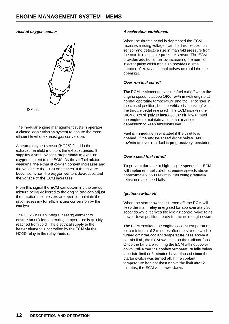
ENGINE MANAGEMENT SYSTEM - MEMS
12 DESCRIPTION AND OPERATION
Heated oxygen sensor
The modular engine management system operatesa closed loop emission system to ensure the mostefficient level of exhaust gas conversion.
A heated oxygen sensor (HO2S) fitted in theexhaust manifold monitors the exhaust gases. Itsupplies a small voltage proportional to exhaustoxygen content to the ECM. As the air/fuel mixtureweakens, the exhaust oxygen content increases andthe voltage to the ECM decreases. If the mixturebecomes richer, the oxygen content decreases andthe voltage to the ECM increases.
From this signal the ECM can determine the air/fuelmixture being delivered to the engine and can adjustthe duration the injectors are open to maintain theratio necessary for efficient gas conversion by thecatalyst.
The HO2S has an integral heating element toensure an efficient operating temperature is quicklyreached from cold. The electrical supply to theheater element is controlled by the ECM via theHO2S relay in the relay module.
Acceleration enrichment
When the throttle pedal is depressed the ECMreceives a rising voltage from the throttle positionsensor and detects a rise in manifold pressure fromthe manifold absolute pressure sensor. The ECMprovides additional fuel by increasing the normalinjector pulse width and also provides a smallnumber of extra additional pulses on rapid throttleopenings.
Over-run fuel cut-off
The ECM implements over-run fuel cut-off when theengine speed is above 1600 rev/min with engine atnormal operating temperature and the TP sensor inthe closed position, i.e. the vehicle is ’coasting’ withthe throttle pedal released. The ECM indexes theIACV open slightly to increase the air flow throughthe engine to maintain a constant manifolddepression to keep emissions low.
Fuel is immediately reinstated if the throttle isopened. If the engine speed drops below 1600rev/min on over-run, fuel is progressively reinstated.
Over-speed fuel cut-off
To prevent damage at high engine speeds the ECMwill implement fuel cut-off at engine speeds aboveapproximately 6500 rev/min; fuel being graduallyreinstated as speed falls.
Ignition switch off
When the starter switch is turned off, the ECM willkeep the main relay energised for approximately 30seconds while it drives the idle air control valve to itspower down position, ready for the next engine start.
The ECM monitors the engine coolant temperaturefor a minimum of 2 minutes after the starter switch isturned off.If the coolant temperature rises above acertain limit, the ECM switches on the radiator fans.Once the fans are running the ECM will not powerdown until either the coolant temperature falls belowa certain limit or 8 minutes have elapsed since thestarter switch was turned off. If the coolanttemperature has not risen above the limit after 2minutes, the ECM will power down.

ENGINE MANAGEMENT SYSTEM - MEMS
ADJUSTMENTS 1
THROTTLE CABLE
Service repair no - 19.20.05
NOTE: Before adjusting cable, ensure thatcable is correctly routed and located. Donot attempt to adjust throttle cable or
engine idle speed by means of the throttle stopscrew.
Adjust
1. Remove air cleaner. See Repairs.
2. Release cable adjusting nut from abutmentbracket.
3. Position outer cable to abutment bracket sothat adjusting nut contacts top of the abutmentbracket.
4. Hold throttle cam in fully closed position,ensure throttle cam contacts throttle stopscrew.
5. Rotate cable adjusting nut until all slack istaken out of inner cable. Ensure throttle doesnot open.
6. Locate throttle cable adjusting nut in abutmentbracket.
7. Operate throttle pedal and ensure that fullthrottle pedal movement is available.
8. Fit air cleaner. See Repairs.

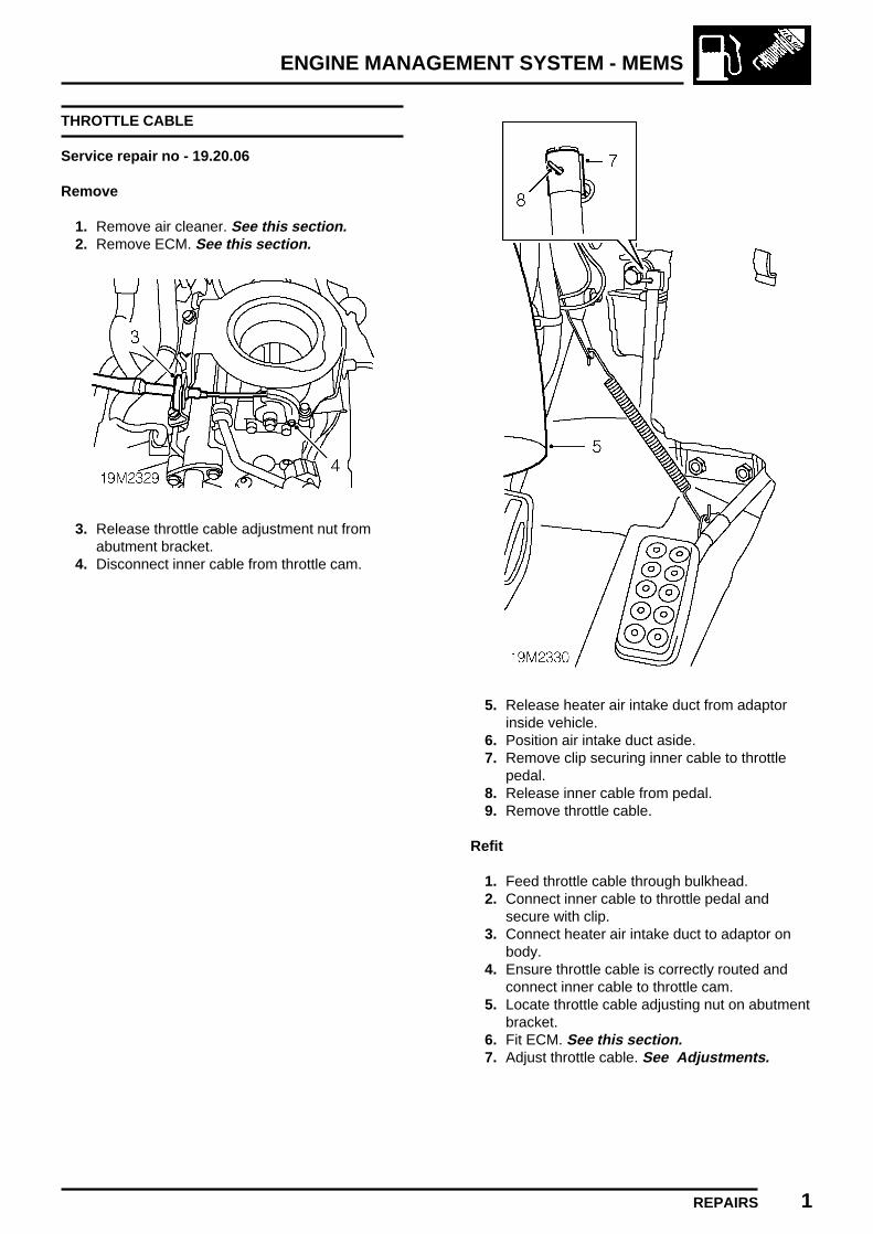
ENGINE MANAGEMENT SYSTEM - MEMS
REPAIRS 1
THROTTLE CABLE
Service repair no - 19.20.06
Remove
1. Remove air cleaner. See this section.2. Remove ECM. See this section.
3. Release throttle cable adjustment nut fromabutment bracket.
4. Disconnect inner cable from throttle cam.
5. Release heater air intake duct from adaptorinside vehicle.
6. Position air intake duct aside.7. Remove clip securing inner cable to throttle
pedal.8. Release inner cable from pedal.9. Remove throttle cable.
Refit
1. Feed throttle cable through bulkhead.2. Connect inner cable to throttle pedal and
secure with clip.3. Connect heater air intake duct to adaptor on
body.4. Ensure throttle cable is correctly routed and
connect inner cable to throttle cam.5. Locate throttle cable adjusting nut on abutment
bracket.6. Fit ECM. See this section.7. Adjust throttle cable. See Adjustments.

ENGINE MANAGEMENT SYSTEM - MEMS
2 REPAIRS
THROTTLE PEDAL
Service repair no - 19.20.01
Remove
1. Release heater air intake duct from adaptorinside vehicle.
2. Position air intake duct aside.3. Remove clip securing inner cable to throttle
pedal.4. Release inner cable from pedal.5. Disconnect return spring from throttle pedal.6. Release carpet retainer and fold back carpet.7. Remove 2 nuts securing throttle pedal to
bulkhead.8. Remove throttle pedal.9. Remove return spring clip from throttle pedal.
Refit
1. Fit return spring clip to throttle pedal.2. Fit throttle pedal to studs on bulkhead.3. Fit nuts securing throttle pedal to bulkhead and
tighten to 25 Nm.4. Connect return spring to pedal.5. Connect inner cable to throttle pedal and
secure with clip.6. Connect heater air intake duct to adaptor on
body.7. Adjust throttle cable. See Adjustments.

ENGINE MANAGEMENT SYSTEM - MEMS
REPAIRS 3
THROTTLE HOUSING
Service repair no - 19.22.45
Remove
1. Disconnect battery earth lead.2. Remove air cleaner. See this section.
3. Release throttle cable adjusting nut fromabutment bracket.
4. Disconnect throttle cable from throttle cam andposition aside.
5. Remove 3 bolts securing air cleaner mountingbracket to fuel rail and inlet manifold.
6. Release 2 clips securing harnesses tomounting bracket.
7. Remove air cleaner mounting bracket.
8. Disconnect air bypass hose from throttle body.9. Disconnect multiplug from TP sensor.
10. Remove 3 bolts securing throttle housing toinlet manifold.
11. Remove throttle housing.12. Remove and discard ’O’ ring from throttle
housing.
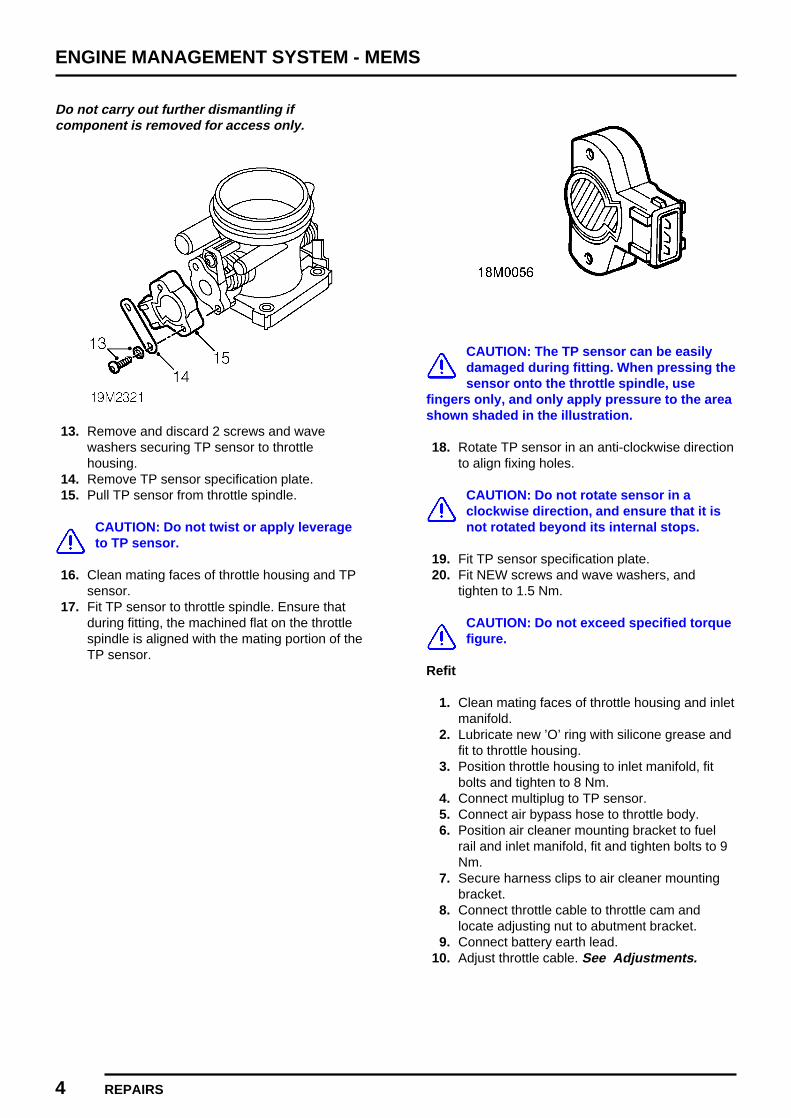
ENGINE MANAGEMENT SYSTEM - MEMS
4 REPAIRS
Do not carry out further dismantling ifcomponent is removed for access only.
13. Remove and discard 2 screws and wavewashers securing TP sensor to throttlehousing.
14. Remove TP sensor specification plate.15. Pull TP sensor from throttle spindle.
CAUTION: Do not twist or apply leverageto TP sensor.
16. Clean mating faces of throttle housing and TPsensor.
17. Fit TP sensor to throttle spindle. Ensure thatduring fitting, the machined flat on the throttlespindle is aligned with the mating portion of theTP sensor.
CAUTION: The TP sensor can be easilydamaged during fitting. When pressing thesensor onto the throttle spindle, use
fingers only, and only apply pressure to the areashown shaded in the illustration.
18. Rotate TP sensor in an anti-clockwise directionto align fixing holes.
CAUTION: Do not rotate sensor in aclockwise direction, and ensure that it isnot rotated beyond its internal stops.
19. Fit TP sensor specification plate.20. Fit NEW screws and wave washers, and
tighten to 1.5 Nm.
CAUTION: Do not exceed specified torquefigure.
Refit
1. Clean mating faces of throttle housing and inletmanifold.
2. Lubricate new ’O’ ring with silicone grease andfit to throttle housing.
3. Position throttle housing to inlet manifold, fitbolts and tighten to 8 Nm.
4. Connect multiplug to TP sensor.5. Connect air bypass hose to throttle body.6. Position air cleaner mounting bracket to fuel
rail and inlet manifold, fit and tighten bolts to 9Nm.
7. Secure harness clips to air cleaner mountingbracket.
8. Connect throttle cable to throttle cam andlocate adjusting nut to abutment bracket.
9. Connect battery earth lead.10. Adjust throttle cable. See Adjustments.

ENGINE MANAGEMENT SYSTEM - MEMS
REPAIRS 5
AIR CLEANER
Service repair no - 19.10.01
Remove
1. Remove 3 screws securing air cleaner tothrottle body. Collect washers.
2. Remove air cleaner.
Refit
1. Clean mating face of air cleaner and throttlebody.
2. Fit air cleaner to throttle body and align.3. Fit screws securing air cleaner to throttle body
and tighten to 7 Nm.
AIR CLEANER ELEMENT
Service repair no - 19.10.10
Remove
1. Remove air cleaner. See this section.
2. Release 4 clips securing 2 halves of aircleaner.
3. Remove upper halve of air cleaner.4. Remove and discard air cleaner element.
Refit
1. Clean inside of air cleaner.2. fit new air cleaner element.3. Position upper half of air cleaner and secure
with clips.4. Fit air cleaner. See this section.
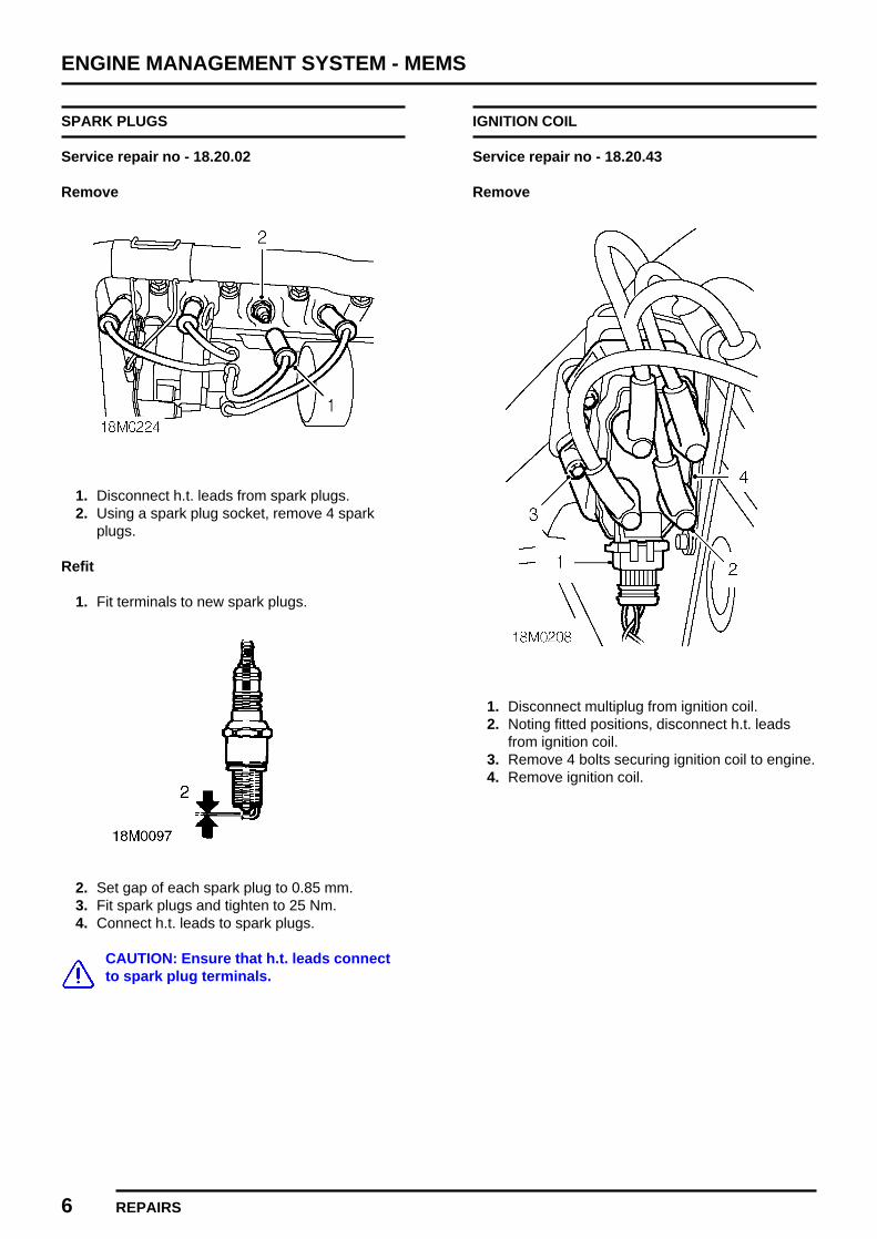
ENGINE MANAGEMENT SYSTEM - MEMS
6 REPAIRS
SPARK PLUGS
Service repair no - 18.20.02
Remove
1. Disconnect h.t. leads from spark plugs.2. Using a spark plug socket, remove 4 spark
plugs.
Refit
1. Fit terminals to new spark plugs.
2. Set gap of each spark plug to 0.85 mm.3. Fit spark plugs and tighten to 25 Nm.4. Connect h.t. leads to spark plugs.
CAUTION: Ensure that h.t. leads connectto spark plug terminals.
IGNITION COIL
Service repair no - 18.20.43
Remove
1. Disconnect multiplug from ignition coil.2. Noting fitted positions, disconnect h.t. leads
from ignition coil.3. Remove 4 bolts securing ignition coil to engine.4. Remove ignition coil.

ENGINE MANAGEMENT SYSTEM - MEMS
REPAIRS 7
Refit
1. Position ignition coil to mounting bracket, fitbolts and tighten to 10 Nm.
2. Identify and connect h.t. leads to ignition coil.3. Connect multiplug to ignition coil.
ENGINE CONTROL MODULE (ECM)
Service repair no - 18.30.01
Remove
1. Disconnect battery earth lead.
2. Remove bolt securing ECM to mountingbracket.
3. Release ECM from mounting bracket.4. Disconnect 2 multiplugs from ECM.5. Remove ECM.

ENGINE MANAGEMENT SYSTEM - MEMS
8 REPAIRS
Refit
1. Position ECM and connect 2 multiplugs.2. Locate ECM on mounting bracket.
CAUTION: Ensure mounting rubbers arecorrectly located in mounting bracket.
3. Fit and tighten bolt securing ECM to mountingbracket to 10 Nm.
4. Connect battery earth lead.
NOTE: If a new ECM has been fitted, theECM will need to be programmed with thecode from the anti-theft security unit using
TestBook, before the engine can be started.
IDLE AIR CONTROL VALVE (IACV)
Service repair no - 18.30.05
Remove
1. Remove air cleaner. See this section.
2. Disconnect air bypass hose from throttle bodyand position aside.
3. Disconnect multiplug from IACV.4. Remove 2 screws securing IACV to inlet
manifold.5. Remove IACV from inlet manifold.6. Remove and discard ’O’ ring from IACV.
Refit
1. Clean mating faces of IACV and inlet manifold.2. Lubricate new ’O’ ring with silicone grease and
fit to IACV.3. Fit IACV to inlet manifold. Fit screws and
tighten to 7 Nm.4. Connect multiplug to IACV.5. Connect air bypass hose to throttle body.6. Fit air cleaner. See this section.
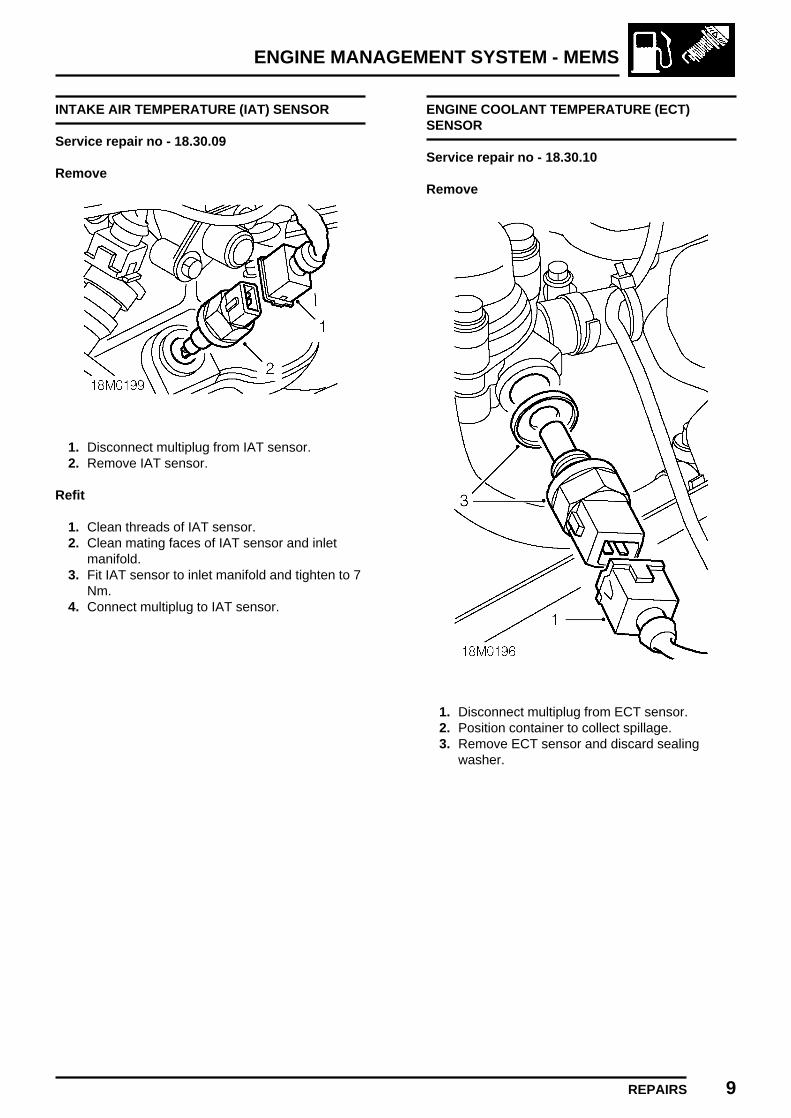
ENGINE MANAGEMENT SYSTEM - MEMS
REPAIRS 9
INTAKE AIR TEMPERATURE (IAT) SENSOR
Service repair no - 18.30.09
Remove
1. Disconnect multiplug from IAT sensor.2. Remove IAT sensor.
Refit
1. Clean threads of IAT sensor.2. Clean mating faces of IAT sensor and inlet
manifold.3. Fit IAT sensor to inlet manifold and tighten to 7
Nm.4. Connect multiplug to IAT sensor.
ENGINE COOLANT TEMPERATURE (ECT)SENSOR
Service repair no - 18.30.10
Remove
1. Disconnect multiplug from ECT sensor.2. Position container to collect spillage.3. Remove ECT sensor and discard sealing
washer.

ENGINE MANAGEMENT SYSTEM - MEMS
10 REPAIRS
Refit
1. Clean threads of ECT sensor.2. Clean mating faces of ECT sensor and
thermostat housing.3. Fit new sealing washer to ECT sensor.4. Fit ECT sensor and tighten to 15 Nm.5. Connect multiplug to ECT sensor.6. Top-up coolant. See
MAINTENANCEMaintenance.
CRANKSHAFT POSITION (CKP) SENSOR
Service repair no - 18.30.12
Remove
1. Disconnect CKP sensor multiplug fromharness.
2. Remove bolt securing CKP sensor multiplug toflywheel housing.
3. Remove 2 bolts securing CKP sensor toflywheel housing.
4. Remove CKP sensor.

ENGINE MANAGEMENT SYSTEM - MEMS
REPAIRS 11
Refit
1. Clean CKP sensor and mating face on flywheelhousing.
2. Position CKP sensor, fit bolts and tighten to 6Nm.
3. Position CKP sensor multiplug to flywheelhousing, fit bolt and tighten to 3 Nm.
4. Connect harness to CKP sensor multiplug.
THROTTLE POSITION (TP) SENSOR
Service repair no - 18.30.17
Remove
1. Remove air cleaner. See this section.
2. Disconnect air bypass hose from throttle body.3. Depress plastic collar on quick release
connector and disconnect brake servo vacuumpipe from inlet manifold.
4. Disconnect multiplug from TP sensor.5. Remove and discard 2 screws and wave
washers securing TP sensor to throttlehousing.
6. Remove TP sensor specification plate.7. Pull TP sensor from throttle spindle.
CAUTION: Do not twist or apply leverageto TP sensor.
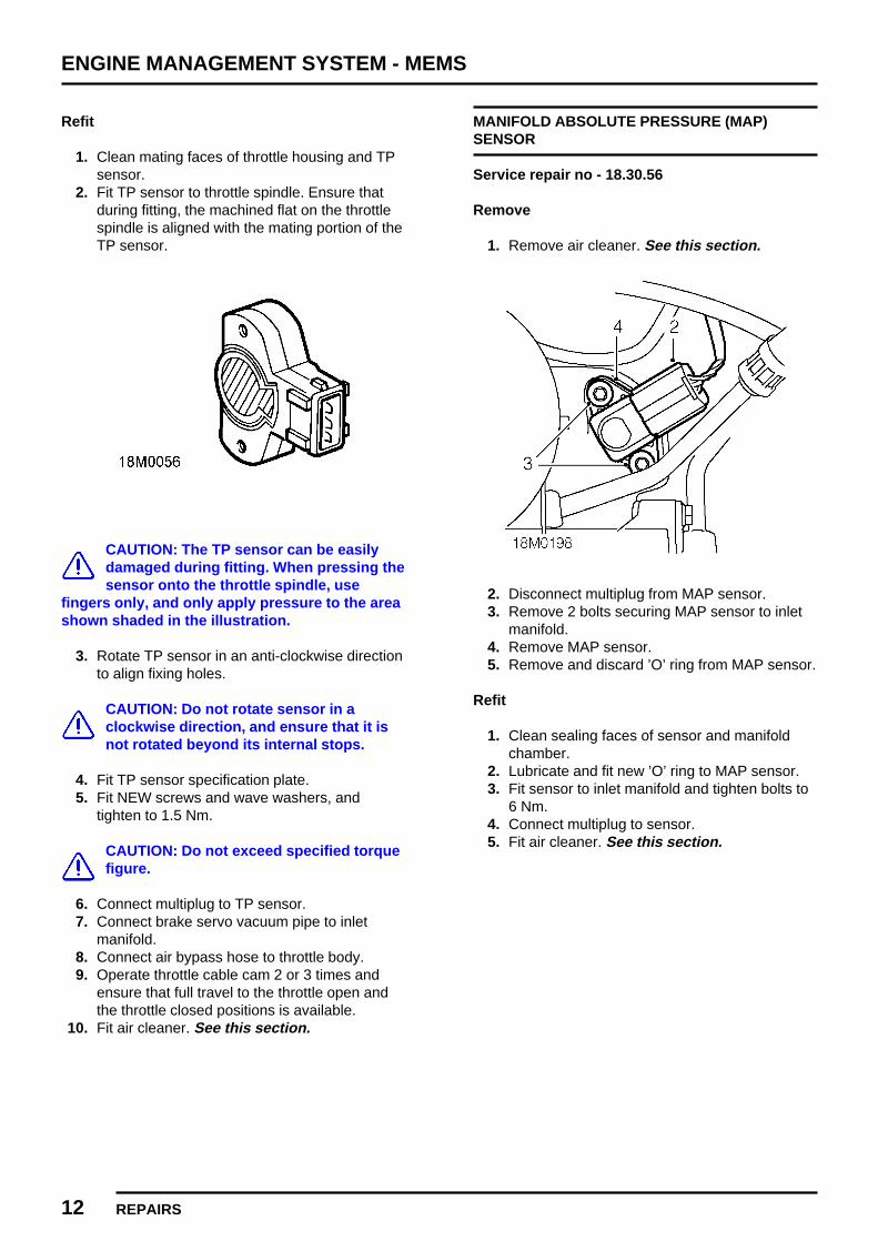
ENGINE MANAGEMENT SYSTEM - MEMS
12 REPAIRS
Refit
1. Clean mating faces of throttle housing and TPsensor.
2. Fit TP sensor to throttle spindle. Ensure thatduring fitting, the machined flat on the throttlespindle is aligned with the mating portion of theTP sensor.
CAUTION: The TP sensor can be easilydamaged during fitting. When pressing thesensor onto the throttle spindle, use
fingers only, and only apply pressure to the areashown shaded in the illustration.
3. Rotate TP sensor in an anti-clockwise directionto align fixing holes.
CAUTION: Do not rotate sensor in aclockwise direction, and ensure that it isnot rotated beyond its internal stops.
4. Fit TP sensor specification plate.5. Fit NEW screws and wave washers, and
tighten to 1.5 Nm.
CAUTION: Do not exceed specified torquefigure.
6. Connect multiplug to TP sensor.7. Connect brake servo vacuum pipe to inlet
manifold.8. Connect air bypass hose to throttle body.9. Operate throttle cable cam 2 or 3 times and
ensure that full travel to the throttle open andthe throttle closed positions is available.
10. Fit air cleaner. See this section.
MANIFOLD ABSOLUTE PRESSURE (MAP)SENSOR
Service repair no - 18.30.56
Remove
1. Remove air cleaner. See this section.
2. Disconnect multiplug from MAP sensor.3. Remove 2 bolts securing MAP sensor to inlet
manifold.4. Remove MAP sensor.5. Remove and discard ’O’ ring from MAP sensor.
Refit
1. Clean sealing faces of sensor and manifoldchamber.
2. Lubricate and fit new ’O’ ring to MAP sensor.3. Fit sensor to inlet manifold and tighten bolts to
6 Nm.4. Connect multiplug to sensor.5. Fit air cleaner. See this section.

ENGINE MANAGEMENT SYSTEM - MEMS
REPAIRS 13
ENGINE MANAGEMENT RELAY MODULE
Service repair no - 18.30.71
The engine management relay module contains thefollowing relays:
Main relayStarter relayFuel pump relayHO2S relay
Remove
1. Release relay module from mounting bracket.2. Disconnect 2 multiplugs from relay module.3. Remove relay module.
Refit
1. Position relay module and connect 2multiplugs. Ensure multiplugs are correctlyengaged.
2. Secure relay module to mounting bracket.
CAMSHAFT POSITION (CMP) SENSOR
Service repair no - 19.22.07
Remove
WARNING: The exhaust manifold reachesvery high temperatures when the engine isrunning and can cause serious burns.
Allow engine to cool before commencing work.
1. Remove air cleaner. See this section.
2. Disconnect multiplug from CMP sensor.3. Remove bolt (8 mm) securing CMP sensor to
cylinder block.4. Remove CMP sensor.5. Remove ’O’ ring from CMP sensor.
Refit
1. Clean sealing faces of sensor and cylinderhead.
2. Lubricate and fit new ’O’ ring to CMP sensor.3. Fit sensor to cylinder block and tighten bolt to
10 Nm.4. Connect multiplug to CMP sensor.5. Fit air cleaner. See this section.

ENGINE MANAGEMENT SYSTEM - MEMS
14 REPAIRS
HEATED OXYGEN SENSOR (HO2S)
Service repair no - 19.22.16
Remove
1. Remove inlet and exhaust manifold gasket.See MANIFOLD & EXHAUST SYSTEMS,Repairs.
2. Using a 22mm open ended spanner, removeHO2S.
3. Remove and discard sealing washer.
Refit
1. Clean mating faces of HO2S and exhaustmanifold.
2. Fit new sealing washer to HO2S.3. Fit HO2S and tighten to 55 Nm.4. Fit inlet and exhaust manifold gasket. See
MANIFOLD & EXHAUST SYSTEMS, Repairs.
FUEL RAIL
Service repair no - 19.60.04
Remove
1. Disconnect battery earth lead.2. Remove air cleaner. See this section.
3. Release throttle cable adjusting nut fromabutment bracket.
4. Disconnect throttle cable from throttle cam andposition aside.
5. Position absorbent cloth around fuel feed pipeto fuel rail connection.
6. Remove 2 bolts securing fuel feed pipe to fuelrail.
7. Release fuel feed pipe from fuel rail.8. Remove and discard ’O’ ring.
CAUTION: Plug the connections.

ENGINE MANAGEMENT SYSTEM - MEMS
REPAIRS 15
9. Disconnect breather hose from throttle bodyand position aside.
10. Depress plastic collar on quick releaseconnector and disconnect brake servo vacuumhose from inlet manifold.
11. Release clip and disconnect vacuum hose fromfuel pressure regulator.
12. Remove 2 bolts securing fuel return pipe to fuelrail.
13. Release fuel return pipe from fuel rail.14. Remove and discard ’O’ ring.
CAUTION: Plug the connections.
15. Disconnect 2 multiplugs from injectors.16. Remove 3 bolts securing air cleaner mounting
bracket to fuel rail and inlet manifold.17. Release 2 clips securing harnesses to
mounting bracket.18. Remove air cleaner mounting bracket.19. Remove 2 spring clips securing fuel rail to
injectors.20. Release fuel rail from injectors and remove.21. Remove and discard ’O’ rings from injectors.

ENGINE MANAGEMENT SYSTEM - MEMS
16 REPAIRS
Refit
1. Lubricate new ’O’ rings with silicone greaseand fit to injectors.
2. Position fuel rail and fit to injectors.3. Fit 2 spring clips securing fuel rail to injectors.4. Position air cleaner mounting bracket to fuel
rail and inlet manifold.5. Align fuel return pipe ’P’ clip to inlet manifold.6. Fit 3 bolts securing air cleaner mounting
bracket to inlet manifold and fuel rail. Tightenbolts to 9 Nm.
7. Secure harness clips to air cleaner mountingbracket.
8. Remove plugs from fuel rail, fuel feed pipe andfuel return pipe.
9. Clean fuel rail and fuel pipe connections.10. Lubricate new ’O’ ring with silicone grease and
fit to fuel return pipe connection.11. Connect fuel return pipe to fuel rail, fit bolts and
tighten to 4 Nm.12. Lubricate new ’O’ ring with silicone grease and
fit to fuel feed pipe connection.13. Connect fuel feed pipe to fuel rail, fit bolts and
tighten to 4 Nm.14. Connect vacuum hose to pressure regulator
and secure with clip.15. Connect brake servo vacuum hose to inlet
manifold.16. Connect breather hose to throttle body.17. Connect throttle cable to throttle cam and
locate adjusting nut to abutment bracket.18. Connect battery earth lead.19. Adjust throttle cable. See Adjustments.
FUEL INJECTORS
Service repair no - 19.60.12
Remove
1. Disconnect battery earth lead.2. Remove fuel rail. See this section.
3. Remove injectors.4. Remove and discard ’O’ rings from injectors.5. Fit protective caps to each end of injectors.
Refit
1. remove protective caps from injectors.2. Clean injectors and recesses in inlet manifold.3. Lubricate new ’O’ rings with silicone grease
and fit to injectors.4. Fit injectors to inlet manifold.5. Fit fuel rail. See this section.6. Connect battery earth lead.

FUEL DELIVERY SYSTEM
CONTENTS Page
ADJUSTMENTS
FUEL SYSTEM - PRESSURE TEST 1........................................................................
REPAIRSFUEL TANK DRAINING 1............................................................................................INERTIA FUEL SHUT-OFF (IFS) SWITCH 1..............................................................FUEL FILTER 2...........................................................................................................FUEL PUMP 3.............................................................................................................FUEL TANK 3..............................................................................................................FUEL TANK BREATHER VALVE 5.............................................................................


FUEL DELIVERY SYSTEM
ADJUSTMENTS 1ISSUED: 12/96
FUEL SYSTEM - PRESSURE TEST
Service repair no - 19.50.13
Remove
1. Position absorbent clotch around fuel line quickfit connector.
2. Release quick fit connector and disconnect fuelfeed hose from fuel pipe.
3. Fit adapter hose 18G 1500-A to fuel pipe.4. Fit adaptor 18G 1500-5 to 18G 1500-A.5. Fit pressure gauge 18G 1500 to 18G 1500-A.6. Connect fuel feed hose quick fit connector to
18G 1500-5.7. Start engine check reading and pressure drop
over one minute and then stop engine.8. Disconnect quick fit connector from 18G
1500-5.9. Remove 18G 1500 from 18G 1500-A.
10. Remove 18g 1500-5 from 18G 1500-A.11. Remove 18G 1500-A from fuel pipe.12. Clean end of fuel pipe.13. Connect fuel feed hose connector to fuel feed
pipe.
CAUTION: Ensure quick fit connector iscorrectly engaged on fuel pipe.
14. Remove cloth positioned to absorb fuelspillage.


FUEL DELIVERY SYSTEM
REPAIRS 1REVISED: 12/96
FUEL TANK DRAINING
Service repair no - 19.55.02
WARNING: Before removing the fuel tankfrom the vehicle it must be drained.
WARNING: Petrol/gasoline vapour ishighly flammable and in confined spacesis also explosive and toxic. Always have a
fire extinguisher containing FOAM, CO2, GAS orPOWDER close at hand when handling ordraining fuel. See GENERAL INFORMATION,Fuel handling precautions.
Drain
1. Remove fuel tank filler cap and allow fuel tankto vent in an open space before commencingwork.
2. Disconnect battery earth lead.3. Using a bowser, drain fuel from the tank into a
sealed container. Follow the manufacturersinstructions for the connection and safe use ofthe bowser.
4. Continue draining until air bubbles appear andfuel ceases to flow.
5. Disconnect bowser from fuel tank.6. Connect battery earth lead.
INERTIA FUEL SHUT-OFF (IFS) SWITCH
Service repair no - 19.22.09
Remove
1. Disconnect multiplug from IFS switch.2. Remove 2 screws securing IFS switch to
mounting bracket.3. Remove IFS switch.
Refit
1. Align IFS switch to mounting bracket.2. Fit screws securing IFS switch to mounting
bracket and tighten to 2 Nm.3. Connect multiplug to IFS switch.4. Press top of IFS switch to reset.
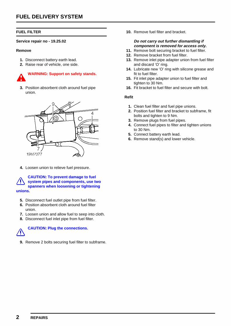
FUEL DELIVERY SYSTEM
2 REPAIRS
FUEL FILTER
Service repair no - 19.25.02
Remove
1. Disconnect battery earth lead.2. Raise rear of vehicle, one side.
WARNING: Support on safety stands.
3. Position absorbent cloth around fuel pipeunion.
4. Loosen union to relieve fuel pressure.
CAUTION: To prevent damage to fuelsystem pipes and components, use twospanners when loosening or tightening
unions.
5. Disconnect fuel outlet pipe from fuel filter.6. Position absorbent cloth around fuel filter
union.7. Loosen union and allow fuel to seep into cloth.8. Disconnect fuel inlet pipe from fuel filter.
CAUTION: Plug the connections.
9. Remove 2 bolts securing fuel filter to subframe.
10. Remove fuel filter and bracket.
Do not carry out further dismantling ifcomponent is removed for access only.
11. Remove bolt securing bracket to fuel filter.12. Remove bracket from fuel filter.13. Remove inlet pipe adapter union from fuel filter
and discard ’O’ ring.14. Lubricate new ’O’ ring with silicone grease and
fit to fuel filter.15. Fit inlet pipe adapter union to fuel filter and
tighten to 30 Nm.16. Fit bracket to fuel filter and secure with bolt.
Refit
1. Clean fuel filter and fuel pipe unions.2. Position fuel filter and bracket to subframe, fit
bolts and tighten to 9 Nm.3. Remove plugs from fuel pipes.4. Connect fuel pipes to filter and tighten unions
to 30 Nm.5. Connect battery earth lead.6. Remove stand(s) and lower vehicle.

FUEL DELIVERY SYSTEM
REPAIRS 3
FUEL PUMP
Service repair no - 19.45.08
Remove
1. Remove fuel tank. See this section.
2. Remove 6 nuts securing fuel pump.3. Remove fuel pump and discard seal.
Refit
1. Clean mating faces fuel pump and fuel tank.2. Using a new seal fit the fuel pump.3. Fit nuts securing fuel pump to fuel tank and
tighten to 9 Nm.4. Fit fuel tank. See this section.
FUEL TANK
Service repair no - 19.55.01
Remove
1. Drain fuel tank. See Adjustments.2. Remove spare wheel.
3. Remove studs securing fuel tank side coverand remove cover.

FUEL DELIVERY SYSTEM
4 REPAIRS
4. Disconnect 2 Lucars from fuel tank sender unit.5. Release clip and disconnect fuel feed hose,
identified by orange coloured band.6. Release clip and disconnect fuel return hose.
CAUTION: Plug the connections.
7. Remove bolt securing fuel tank retaining strapand move strap aside.
8. Release tank from filler neck grommet.9. Manoeuvre fuel tank into boot space.
10. Release clip and disconnect breather hosefrom pipe.
CAUTION: Plug the connections.
11. Disconnect multiplug from fuel pump.12. Remove fuel tank.
Do not carry out further dismantling ifcomponent is removed for access only.
13. Release clip and disconnect breather hosefrom tank.
14. Release breather pipe from clips.15. Remove nut securing breather valve to fuel
tank and remove breather valve.
CAUTION: Plug the connections.
16. Remove 6 nuts securing fuel pump to tank.17. Remove fuel pump and discard seal.18. Remove filler neck seal.

FUEL DELIVERY SYSTEM
REPAIRS 5
19. Using tool 18G 1467 remove fuel gaugesender unit and discard seal.
Refit
1. Clean mating faces of fuel tank and senderunit.
2. Using a new seal fit sender unit to fuel tank.3. Clean mating faces of fuel pump and fuel tank.4. Using a new seal fit the fuel pump to fuel tank.5. Fit nuts securing fuel pump to fuel tank and
tighten to 9 Nm.6. Fit breather valve to fuel tank, fit nut and
tighten to 9 Nm.7. Connect breather hose to fuel tank and secure
with clip.8. Secure hose to clips on tank.9. Fit seal to filler neck.
10. Position tank in vehicle.11. Connect breather hose to pipe and secure with
clip.12. Connect multiplug to fuel pump.13. Manoeuvre tank into position and position
restraining strap.14. Fit and tighten strap retaining bolt.15. Connect fuel feed and return hoses and to fuel
tank and secure with clips.16. Connect Lucars to sender unit.17. Fit fuel tank side cover and secure with studs.18. Fit spare wheel.19. Refill fuel tank with fuel.20. Connect battery earth lead.
FUEL TANK BREATHER VALVE
Service repair no - 19.55.25
Remove
1. Disconnect battery earth lead.2. Remove fuel tank. See this section.
3. Release clip and disconnect breather hosefrom fuel tank.
4. Release breather pipe from clips.5. Remove nut securing bracket and remove two
way valve assembly.
CAUTION: Plug the connections.
Refit
1. Fit two way valve and bracket to fuel tank. Fitnut and tighten to 9 Nm.
2. Connect two way valve hose to fuel tank andsecure with clip.
3. Secure hose in clips.4. Refit fuel tank. See this section.


COOLING SYSTEM
CONTENTS Page
DESCRIPTION AND OPERATION
COOLING SYSTEM COMPONENTS 1.......................................................................COOLING SYSTEM OPERATION 2...........................................................................
ADJUSTMENTSDRAIN AND REFILL 1.................................................................................................
REPAIRSCOOLANT EXPANSION TANK 1................................................................................COOLANT PUMP PULLEY 2......................................................................................RADIATOR COOLING FAN 2......................................................................................COOLING FAN RELAY 3............................................................................................RADIATOR 4...............................................................................................................THERMOSTAT 5.........................................................................................................COOLANT PUMP 6.....................................................................................................


COOLING SYSTEM
DESCRIPTION AND OPERATION 1
COOLING SYSTEM COMPONENTS
1. Top hose2. Radiator upper mounting3. Thermostat housing4. Hose - expansion tank to thermostat5. Expansion tank
6. Bottom hose7. Coolant pump8. Radiator9. Cooling fan and cowl

COOLING SYSTEM
2 DESCRIPTION AND OPERATION REVISED: 12/96
COOLING SYSTEM OPERATION
Flow diagram
A = COLD B = HOT
COOLING SYSTEM
DESCRIPTION AND OPERATION 3
Operation
The cooling system employed is the bypass type.
When the engine is cold the thermostat closes off the coolant feed from the radiator bottom hose (1). Coolant in thecylinder head and heater matrix (2) begins to rise in temperature after the engine is started. The heater is regulatedby a control valve (3) from the dashboard. Coolant circulates back into the heater circuit through a by-pass hose (4)prior to the thermostat opening.
As temperature increases the thermostat (5) gradually opens, allowing hot coolant to flow to the radiator (6) via thetop hose (7). As the thermostat opens further so the full flow of coolant is drawn through the radiator.
Any excess coolant created by heat expansion is returned to the expansion tank (8) via hose (9).
The radiator is an aluminium cross-flow type with integral end tanks and is mounted on rubber bushes directly intothe subframe transverse member. The top of the radiator is supported by means of mounting brackets bolted to theradiator and bonnet locking platform.
For additional air flow, at times when the vehicle is stationary, an electric cooling fan is fitted. It is triggered by theEngine Control Module (ECM).
The coolant pump (10) is a rotor type pump which draws coolant directly from the radiator. The pump is driven by apoly-V pulley from the alternator drive belt.


COOLING SYSTEM
ADJUSTMENTS 1
DRAIN AND REFILL
Service repair no - 26.10.01
Drain
1. Visually check engine and cooling system forsigns of coolant leaks.
2. Examine hose for signs of cracking, distortionand security of connections.
3. Position heater temperature control tomaximum heat position.
4. Remove expansion tank filler cap.5. Position drain tin to collect coolant.6. Loosen clip and disconnect bottom hose from
radiator.7. Allow cooling system to drain.
Refill
1. Flush system with water under low pressure.
CAUTION: High pressure water coulddamage the radiator.
2. Connect bottom hose to radiator and tightenclip.
3. Prepare coolant to required concentration. SeeINFORMATION, Capacities, fluids andlubricants.
4. Turn heater temperature control to maximumheat position.
5. Fill system slowly until coolant level reaches’MAX’ mark on expansion tank.
6. Start and run engine until radiator cooling fanoperates.
7. Switch off engine and allow to cool.8. Check for leaks and top-up coolant to ’MAX’
mark on expansion tank.


COOLING SYSTEM
REPAIRS 1
COOLANT EXPANSION TANK
Service repair no - 26.15.01
Remove
1. Drain cooling system. See Adjustments.
2. Loosen clip and disconnect hose fromexpansion tank.
3. Remove 2 nuts securing expansion tank tomounting bracket.
4. Release expansion tank from mounting5. Release clip and disconnect coolant feed hose
from expansion tank.6. Remove coolant expansion tank.
Refit
1. Position coolant expansion tank.2. Connect coolant feed hose to expansion tank
and secure with clip.3. Position expansion tank on mounting bracket,
fit nuts and tighten to 10 Nm.4. Connect hose to expansion tank and tighten
clip.5. Refill cooling system. See Adjustments.

COOLING SYSTEM
2 REPAIRS
COOLANT PUMP PULLEY
Service repair no - 26.25.03
Remove
1. Loosen 4 bolts securing coolant pump pulley.2. Remove auxiliary drive belt. See
ELECTRICAL, Repairs.3. Remove 4 bolts securing coolant pump pulley.4. Remove pulley.
Refit
1. Ensure mating faces of pulley and coolantpump flange are clean.
2. Fit pulley to pump and tighten bolts to 10 Nm.3. Fit auxiliary drive belt. See ELECTRICAL,
Repairs.
RADIATOR COOLING FAN
Service repair no - 26.25.22
Remove
1. Remove front grille. See BODY, Exteriorfittings.
2. Disconnect radiator cooling fan multiplug fromharness.
3. Remove 4 bolts securing 2 upper radiatormounting bracket to bonnet locking platform.
4. Remove 2 upper radiator mounting brackets.5. Remove bolt securing cooling fan multiplug to
radiator.6. Release radiator from lower mountings.7. Manoeuvre radiator to gain access to bolts and
remove 4 bolts securing cooling fan to radiator.8. Remove radiator cooling fan.
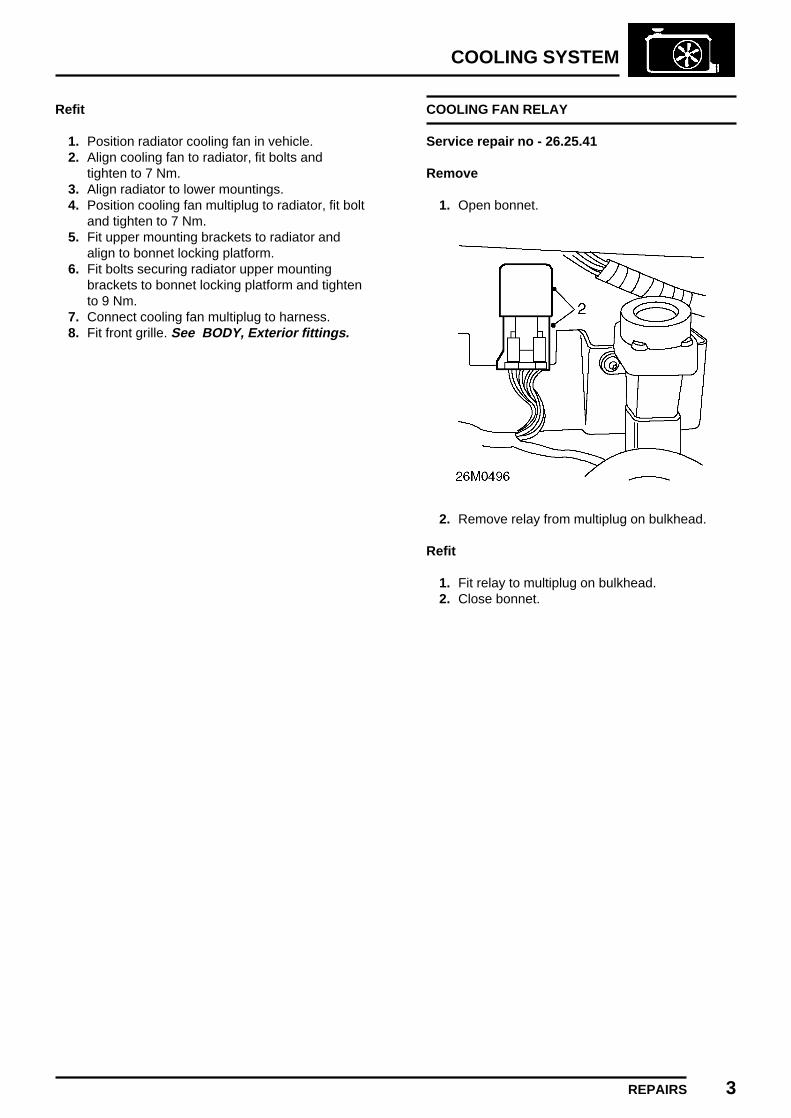
COOLING SYSTEM
REPAIRS 3
Refit
1. Position radiator cooling fan in vehicle.2. Align cooling fan to radiator, fit bolts and
tighten to 7 Nm.3. Align radiator to lower mountings.4. Position cooling fan multiplug to radiator, fit bolt
and tighten to 7 Nm.5. Fit upper mounting brackets to radiator and
align to bonnet locking platform.6. Fit bolts securing radiator upper mounting
brackets to bonnet locking platform and tightento 9 Nm.
7. Connect cooling fan multiplug to harness.8. Fit front grille. See BODY, Exterior fittings.
COOLING FAN RELAY
Service repair no - 26.25.41
Remove
1. Open bonnet.
2. Remove relay from multiplug on bulkhead.
Refit
1. Fit relay to multiplug on bulkhead.2. Close bonnet.

COOLING SYSTEM
4 REPAIRS REVISED: 12/96
RADIATOR
Service repair no - 26.40.01
Remove
1. Drain cooling system. See Adjustments.2. Remove front grille. See BODY, Exterior
fittings.3. Remove alternator. See ELECTRICAL,
Repairs.
4. Loosen clip and disconnect top hose fromradiator.
5. Disconnect radiator cooling fan multiplug fromharness.
6. Remove 4 bolts securing 2 upper radiatormounting bracket to bonnet locking platform.
7. Remove 2 upper radiator mounting brackets.8. Release radiator from lower mountings.9. Remove radiator from vehicle.
Do not carry out further dismantling ifcomponent is removed for access only.
10. Remove bolt securing cooling fan multiplug toradiator.
11. Remove 4 bolts securing cooling fan to radiatorand remove cooling fan.
12. Align cooling fan to radiator, fit bolts andtighten to 7 Nm.
13. Position cooling fan multiplug to radiator, fit boltand tighten to 7 Nm.
Refit
1. Position radiator in vehicle.2. Align radiator to lower mountings.3. Fit upper mounting brackets to radiator and
align to bonnet locking platform.4. Fit bolts securing radiator upper mounting
brackets to bonnet locking platform and tightento 9 Nm.
5. Connect cooling fan multiplug to harness.6. Connect top hose to radiator and tighten clip.7. Fit alternator. See ELECTRICAL, Repairs.8. Fit front grille. See BODY, Exterior fittings.9. Refill cooling system. See Adjustments.

COOLING SYSTEM
REPAIRS 5
THERMOSTAT
Service repair no - 26.45.09
Remove
1. Disconnect battery earth lead.2. Drain cooling system. See Adjustments.
3. Loosen clip and disconnect top hose fromthermostat housing.
4. Loosen clip and disconnect expansion tankhose from thermostat housing.
5. Loosen clip and disconnect heater hose fromthermostat housing.
6. Disconnect multiplug from ECT sensor.7. Remove 3 bolts securing thermostat housing.8. Remove thermostat upper housing and discard
gasket.9. Remove thermostat.
10. Remove thermostat lower housing and discardgasket.
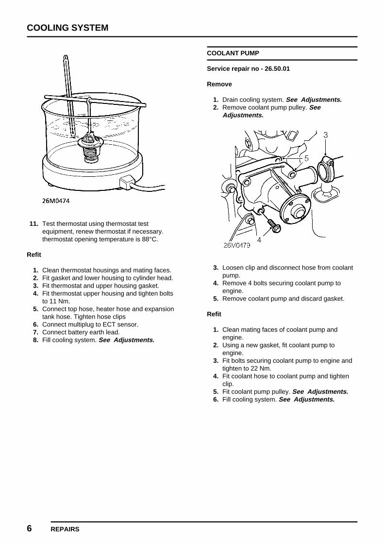
COOLING SYSTEM
6 REPAIRS
11. Test thermostat using thermostat testequipment, renew thermostat if necessary.thermostat opening temperature is 88°C.
Refit
1. Clean thermostat housings and mating faces.2. Fit gasket and lower housing to cylinder head.3. Fit thermostat and upper housing gasket.4. Fit thermostat upper housing and tighten bolts
to 11 Nm.5. Connect top hose, heater hose and expansion
tank hose. Tighten hose clips6. Connect multiplug to ECT sensor.7. Connect battery earth lead.8. Fill cooling system. See Adjustments.
COOLANT PUMP
Service repair no - 26.50.01
Remove
1. Drain cooling system. See Adjustments.2. Remove coolant pump pulley. See
Adjustments.
3. Loosen clip and disconnect hose from coolantpump.
4. Remove 4 bolts securing coolant pump toengine.
5. Remove coolant pump and discard gasket.
Refit
1. Clean mating faces of coolant pump andengine.
2. Using a new gasket, fit coolant pump toengine.
3. Fit bolts securing coolant pump to engine andtighten to 22 Nm.
4. Fit coolant hose to coolant pump and tightenclip.
5. Fit coolant pump pulley. See Adjustments.6. Fill cooling system. See Adjustments.
MANIFOLD & EXHAUST SYSTEMS
CONTENTS Page
DESCRIPTION AND OPERATION
EXHAUST SYSTEM COMPONENTS 1......................................................................EXHAUST MANIFOLD COMPONENTS 2...................................................................INLET MANIFOLD COMPONENTS 3.........................................................................INLET MANIFOLD 4....................................................................................................EXHAUST MANIFOLD 4.............................................................................................EXHAUST SYSTEM 4.................................................................................................
REPAIRSFRONT PIPE 1............................................................................................................TAIL PIPE 1.................................................................................................................FRONT PIPE TO MANIFOLD GASKET 2...................................................................INTERMEDIATE PIPE HEAT SHIELD 3.....................................................................INLET MANIFOLD 4....................................................................................................EXHAUST MANIFOLD 5.............................................................................................INLET AND EXHAUST MANIFOLD GASKET 6..........................................................


MANIFOLD & EXHAUST SYSTEMS
DESCRIPTION AND OPERATION 1
EXHAUST SYSTEM COMPONENTS
1. Gasket - front pipe to manifold2. Front pipe3. Nut - Front pipe to manifold4. Nut - Front pipe to catalytic converter5. Gasket - front pipe to catalytic converter
6. Catalytic converter7. Nut - Tail pipe to catalytic converter8. Tail pipe9. Mounting rubbers

MANIFOLD & EXHAUST SYSTEMS
2 DESCRIPTION AND OPERATION
EXHAUST MANIFOLD COMPONENTS
1. Bolt - Heat shield to exhaust manifold2. Heat shield3. Exhaust manifold
4. Sealing washer - HO2S5. Heated Oxygen Sensor - (HO2S)

MANIFOLD & EXHAUST SYSTEMS
DESCRIPTION AND OPERATION 3
INLET MANIFOLD COMPONENTS
1. Throttle housing2. Bolt - Throttle housing to inlet manifold3. ’O’ ring - Throttle housing to inlet manifold4. Bolt - MAP sensor to inlet manifold5. MAP sensor6. ’O’ ring - MAP sensor to inlet manifold7. Fuel rail and injectors
8. Bolt - Fuel rail to inlet manifold9. ’O’ ring - Injector to inlet manifold
10. Inlet manifold11. Bolt - IACV to inlet manifold12. Idle Air Control Valve (IACV)13. ’O’ ring - IACV to inlet manifold14. Inlet manifold locating ring

MANIFOLD & EXHAUST SYSTEMS
4 DESCRIPTION AND OPERATION
INLET MANIFOLD
The inlet manifold is an aluminium casting, whichincorporates a throttle housing, MAP sensor, IACV,IAT sensor, fuel rail and injectors. The inlet manifoldis attached to the cylinder head and sealed by twolocating rings and a gasket.
EXHAUST MANIFOLD
The cast iron exhaust manifold is fitted with aHeated Oxygen Sensor (HO2S). To assist theextraction of exhaust gases the manifold is dividedinto two outlets, No.2 and 3 cylinders discharge intoone half of the manifold and No.1 and 4 cylindersinto the other half.
EXHAUST SYSTEM
The exhaust system consists of a front pipe,catalytic converter and a silencer/tail pipe assembly,which incorporates two silencers. Both silencerscontain a series of expansion chambers, resonatorsand baffles designed to give an improved exhaustsystem, reduce condensation and increase the life ofthe system.
The catalytic converter operates in ’closed loop’system. A Heated Oxygen Sensor (HO2S), locatedin the exhaust manifold is used to monitor theexhaust gases and provide a signal to the EngineControl Module (ECM). The ECM uses this signal tomodify the fuelling and maintain emissionsacceptable to the catalytic converter. For informationon the operation of the catalytic converter. SeeEMISSION CONTROL, Description and operation.
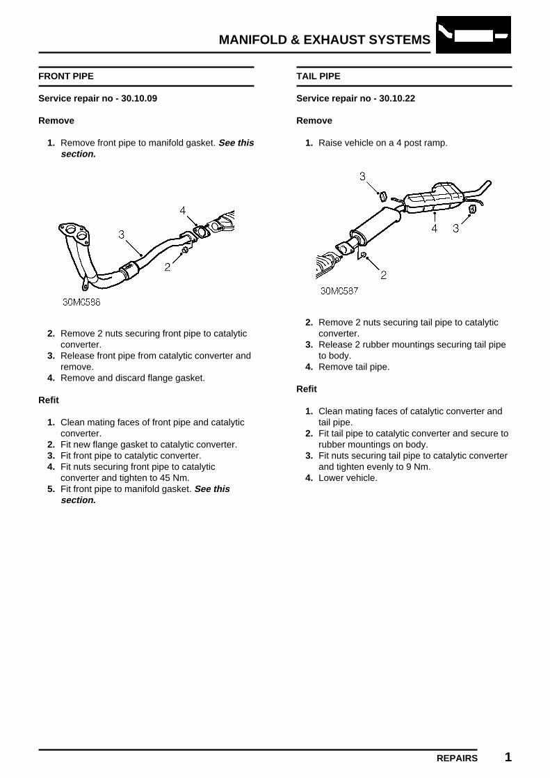
MANIFOLD & EXHAUST SYSTEMS
REPAIRS 1
FRONT PIPE
Service repair no - 30.10.09
Remove
1. Remove front pipe to manifold gasket. See thissection.
2. Remove 2 nuts securing front pipe to catalyticconverter.
3. Release front pipe from catalytic converter andremove.
4. Remove and discard flange gasket.
Refit
1. Clean mating faces of front pipe and catalyticconverter.
2. Fit new flange gasket to catalytic converter.3. Fit front pipe to catalytic converter.4. Fit nuts securing front pipe to catalytic
converter and tighten to 45 Nm.5. Fit front pipe to manifold gasket. See this
section.
TAIL PIPE
Service repair no - 30.10.22
Remove
1. Raise vehicle on a 4 post ramp.
2. Remove 2 nuts securing tail pipe to catalyticconverter.
3. Release 2 rubber mountings securing tail pipeto body.
4. Remove tail pipe.
Refit
1. Clean mating faces of catalytic converter andtail pipe.
2. Fit tail pipe to catalytic converter and secure torubber mountings on body.
3. Fit nuts securing tail pipe to catalytic converterand tighten evenly to 9 Nm.
4. Lower vehicle.

MANIFOLD & EXHAUST SYSTEMS
2 REPAIRS
FRONT PIPE TO MANIFOLD GASKET
Service repair no - 30.10.26
Remove
1. Raise front of vehicle.
WARNING: Support on safety stands.
2. Disconnect battery earth lead.
3. Remove 3 nuts securing front pipe to exhaustmanifold.
4. Remove nut and bolt securing front pipe tomounting bracket on differential housing.
5. Release front pipe from exhaust manifold.6. Remove gasket from manifold flange.
Refit
1. Clean manifold and front pipe flanges.2. Fit new gasket to exhaust manifold flange.3. Align front pipe to exhaust manifold.4. Fit nuts securing front pipe to manifold and
tighten to 22 Nm.5. Align front pipe clamp to bracket on differential
housing, fit nut and bolt and tighten to 22 Nm.6. Remove stand(s) and lower vehicle.7. Connect battery earth lead.

MANIFOLD & EXHAUST SYSTEMS
REPAIRS 3
INTERMEDIATE PIPE HEAT SHIELD
Service repair no - 30.10.62
Remove
1. Raise vehicle on a 4 post ramp.
2. Remove 4 nuts securing intermediate pipe heatshield to body.
3. Release heat shield from studs and slideforward.
4. Manoeuvre heat shield around exhaust pipeand remove.
Refit
1. Manoeuvre heat shield into position and locateon studs.
2. Fit and tighten nuts securing heat shield tobody.
3. Lower vehicle.

MANIFOLD & EXHAUST SYSTEMS
4 REPAIRS
INLET MANIFOLD
Service repair no - 30.15.02
Remove
1. Remove inlet and exhaust manifold gasket.See this section.
2. Remove 2 screws securing MAP sensor to inletmanifold.
3. Remove MAP sensor and discard ’O’ ring.4. Remove IAT sensor and adaptor.5. Disconnect pressure regulator vacuum hose
from inlet manifold.6. Release fuel injectors from inlet manifold.7. Remove fuel rail and injectors.
8. Remove and discard ’O’ rings from injectors.9. Disconnect air bypass hose from throttle body.
10. Remove 3 bolts securing throttle body to inletmanifold.
11. Remove throttle body and discard ’O’ ring.12. Remove 4 screws securing IACV to inlet
manifold.13. Remove IACV and discard ’O’ ring.

MANIFOLD & EXHAUST SYSTEMS
REPAIRS 5
Refit
1. Clean mating face of IACV and inlet manifold.2. Lubricate new ’O’ ring with silicone grease and
fit to IACV.3. Fit IACV to inlet manifold, fit screws and tighten
to 7 Nm.4. Clean mating face of inlet manifold and throttle
body.5. Lubricate new ’O’ ring with silicone grease and
fit to throttle body.6. Fit throttle body to inlet manifold, fit bolts and
tighten to 8 Nm.7. Connect air bypass hose to throttle body.8. Clean injectors and recesses in inlet manifold.9. Lubricate new ’O’ rings with silicone grease
and fit to fuel injector.10. Fit fuel rail and injector assembly to inlet
manifold.11. Connect pressure regulator vacuum hose to
inlet manifold.12. Clean mating face of IAT sensor and inlet
manifold.13. Fit IAT sensor and adaptor to inlet manifold,
tighten to 7 Nm.14. Clean mating face of MAP sensor and inlet
manifold.15. Lubricate and fit new ’O’ ring to MAP sensor.16. Fit MAP sensor to inlet manifold, fit screws and
tighten to 6 Nm.17. Fit inlet and exhaust manifold gasket. See this
section.
EXHAUST MANIFOLD
Service repair no - 30.15.10
Remove
1. Remove inlet and exhaust manifold gasket.See this section.
2. Using a 22 mm open ended spanner, removeHO2S.
3. Remove and discard sealing washer.4. Remove 3 bolts securing heat shield to
exhaust manifold.5. Remove exhaust manifold heat shield.
Refit
1. Position heat shield to exhaust manifold, fit andtighten bolts.
2. Clean mating faces of HO2S and exhaustmanifold.
3. Fit new sealing washer to HO2S.4. Fit HO2S and tighten to 55 Nm.5. Fit inlet and exhaust manifold gasket. See this
section.
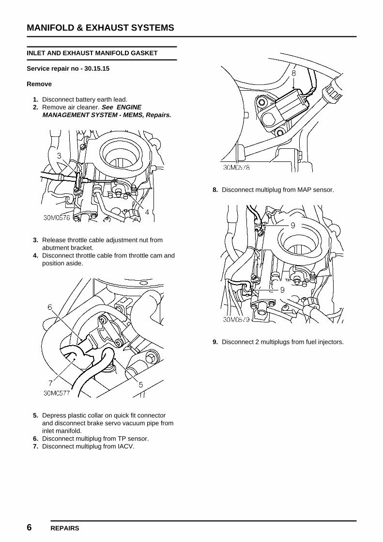
MANIFOLD & EXHAUST SYSTEMS
6 REPAIRS
INLET AND EXHAUST MANIFOLD GASKET
Service repair no - 30.15.15
Remove
1. Disconnect battery earth lead.2. Remove air cleaner. See ENGINE
MANAGEMENT SYSTEM - MEMS, Repairs.
3. Release throttle cable adjustment nut fromabutment bracket.
4. Disconnect throttle cable from throttle cam andposition aside.
5. Depress plastic collar on quick fit connectorand disconnect brake servo vacuum pipe frominlet manifold.
6. Disconnect multiplug from TP sensor.7. Disconnect multiplug from IACV.
8. Disconnect multiplug from MAP sensor.
9. Disconnect 2 multiplugs from fuel injectors.

MANIFOLD & EXHAUST SYSTEMS
REPAIRS 7
10. Disconnect multiplug from IAT sensor.11. Position absorbent cloth around fuel line quick
fit connectors.
12. Release quick fit connector and disconnect fuelreturn hose from fuel pipe.
13. Release quick fit connector and disconnect fuelfeed hose from fuel pipe.
CAUTION: Plug the connections.
14. Remove 3 bolts securing air cleaner mountingbracket to fuel rail and inlet manifold.
15. Release 2 clips securing harnesses tomounting bracket.
16. Remove air cleaner mounting bracket.
17. Disconnect breather hose from inlet manifold.18. Release clip and disconnect evaporative
emission canister purge hose from inletmanifold.

MANIFOLD & EXHAUST SYSTEMS
8 REPAIRS
19. Remove 4 nuts securing inlet manifold tocylinder head.
20. Remove inlet manifold.21. Collect 2 locating rings.22. Remove front pipe to manifold gasket. See this
section.
23. Disconnect HO2S multiplug from harness.24. Release cable tie securing HO2S lead to
harness.
25. Remove 2 nuts and washers securing exhaustmanifold to cylinder head.
26. Remove bolt securing breather pipe to cylinderhead.
27. Release breather pipe from exhaust manifoldstud.
28. Remove exhaust manifold.29. Remove and discard exhaust manifold gasket.
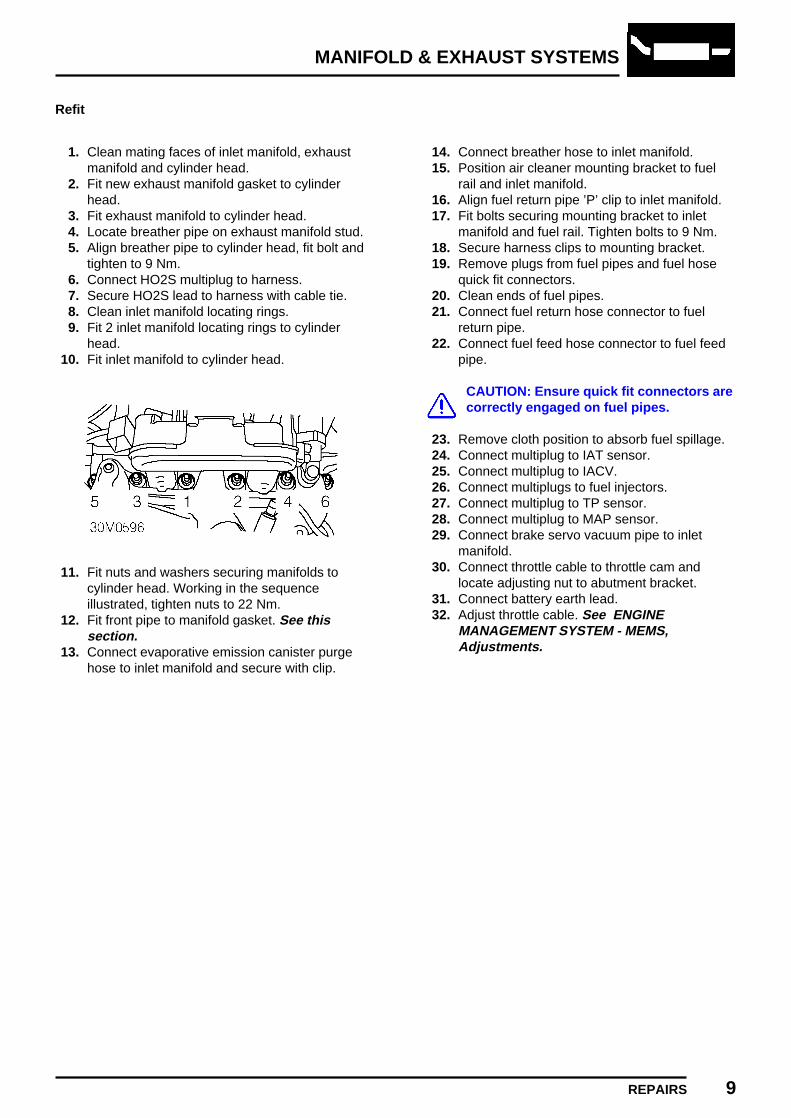
MANIFOLD & EXHAUST SYSTEMS
REPAIRS 9
Refit
1. Clean mating faces of inlet manifold, exhaustmanifold and cylinder head.
2. Fit new exhaust manifold gasket to cylinderhead.
3. Fit exhaust manifold to cylinder head.4. Locate breather pipe on exhaust manifold stud.5. Align breather pipe to cylinder head, fit bolt and
tighten to 9 Nm.6. Connect HO2S multiplug to harness.7. Secure HO2S lead to harness with cable tie.8. Clean inlet manifold locating rings.9. Fit 2 inlet manifold locating rings to cylinder
head.10. Fit inlet manifold to cylinder head.
11. Fit nuts and washers securing manifolds tocylinder head. Working in the sequenceillustrated, tighten nuts to 22 Nm.
12. Fit front pipe to manifold gasket. See thissection.
13. Connect evaporative emission canister purgehose to inlet manifold and secure with clip.
14. Connect breather hose to inlet manifold.15. Position air cleaner mounting bracket to fuel
rail and inlet manifold.16. Align fuel return pipe ’P’ clip to inlet manifold.17. Fit bolts securing mounting bracket to inlet
manifold and fuel rail. Tighten bolts to 9 Nm.18. Secure harness clips to mounting bracket.19. Remove plugs from fuel pipes and fuel hose
quick fit connectors.20. Clean ends of fuel pipes.21. Connect fuel return hose connector to fuel
return pipe.22. Connect fuel feed hose connector to fuel feed
pipe.
CAUTION: Ensure quick fit connectors arecorrectly engaged on fuel pipes.
23. Remove cloth position to absorb fuel spillage.24. Connect multiplug to IAT sensor.25. Connect multiplug to IACV.26. Connect multiplugs to fuel injectors.27. Connect multiplug to TP sensor.28. Connect multiplug to MAP sensor.29. Connect brake servo vacuum pipe to inlet
manifold.30. Connect throttle cable to throttle cam and
locate adjusting nut to abutment bracket.31. Connect battery earth lead.32. Adjust throttle cable. See ENGINE
MANAGEMENT SYSTEM - MEMS,Adjustments.


CLUTCH
CONTENTS Page
ADJUSTMENTS
THROW-OUT STOP CLEARANCE 1..........................................................................CLUTCH BLEED 2.......................................................................................................
REPAIRSFLYWHEEL HOUSING COVER 1...............................................................................CLUTCH ASSEMBLY AND RELEASE BEARING 6....................................................RELEASE BEARING 8................................................................................................MASTER CYLINDER 8................................................................................................SLAVE CYLINDER 10.................................................................................................


CLUTCH
ADJUSTMENTS 1
THROW-OUT STOP CLEARANCE
Service repair no - 33.25.03
Check and Adjust
1. Remove ECM. See ENGINE MANAGEMENTSYSTEM - MEMS, Repairs.
2. Release engine compartment fuse box fromECM mounting bracket.
3. Release clip securing main harness to ECM
mounting bracket.4. Remove bolt securing ECM mounting bracket
to body.5. Release ECM mounting bracket from body and
remove.6. Depress clutch pedal to load clutch lever and
remove any free play.

CLUTCH
2 ADJUSTMENTS REVISED: 12/96
7. Measure clearance between throw out stoplock nut and flywheel housing cover.
8. The correct clearance is 6.5 mm. If theclearance is incorrect, loosen lock nut andadjust throw out stop to obtain correctclearance.
9. Tighten lock nut and recheck clearance.10. Locate ECM mounting bracket on body, fit bolt
and tighten to 10 Nm.11. Secure clip on main harness to ECM mounting
bracket.12. Secure engine compartment fuse box to ECM
mounting bracket.13. Fit ECM. See ENGINE MANAGEMENT
SYSTEM - MEMS, Repairs.
CLUTCH BLEED
Service repair no - 33.15.01
Bleed
CAUTION: Never reuse fluid that has beenbled from the system. Do not allow fluidlevel in master cylinder to fall below half
during bleeding.
CAUTION: Do not allow fluid to contactpaint finished surfaces as paint may bedamaged. If spilled, remove fluid and
clean area with warm water.
1. Remove ECM. See ENGINE MANAGEMENTSYSTEM - MEMS, Repairs.
2. Top up the clutch master cylinder with brakefluid. See INFORMATION, Capacities, fluidsand lubricants.
3. Attach bleed tube to bleed screw on clutchslave cylinder and submerge free end in aclear container containing fluid.
4. Open the bleed screw three-quarters of a turn,depress the clutch pedal slowly, tighten bleedscrew whilst holding pedal at end of downwardstroke. Allow pedal to return and repeatprocedure until a flow of clean air-free fluid ispurged into container.
CAUTION: Maintain fluid level above halfin reservoir during this procedure.
5. Tighten bleed screw and remove bleed tube.6. Top up the clutch master cylinder.7. Fit ECM. See ENGINE MANAGEMENT
SYSTEM - MEMS, Repairs.
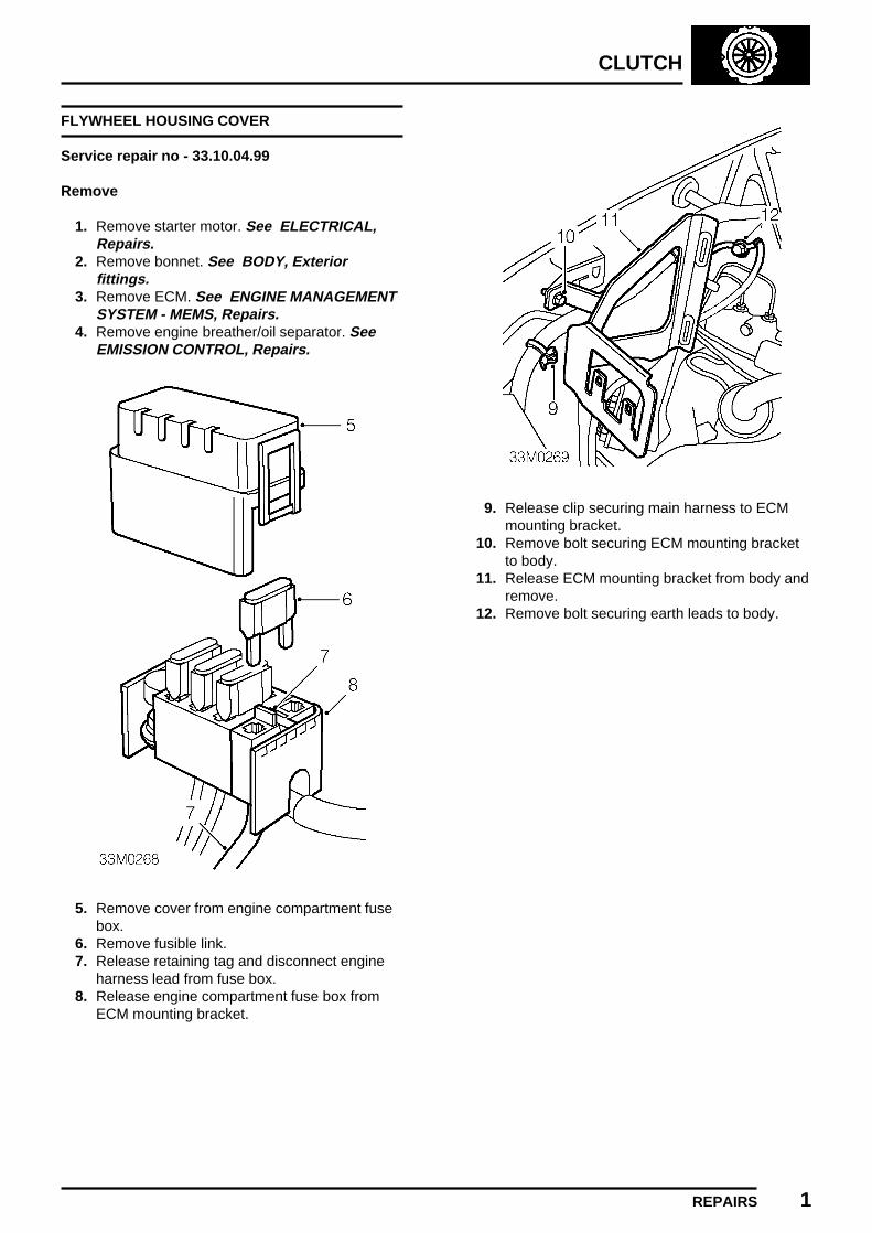
CLUTCH
REPAIRS 1
FLYWHEEL HOUSING COVER
Service repair no - 33.10.04.99
Remove
1. Remove starter motor. See ELECTRICAL,Repairs.
2. Remove bonnet. See BODY, Exteriorfittings.
3. Remove ECM. See ENGINE MANAGEMENTSYSTEM - MEMS, Repairs.
4. Remove engine breather/oil separator. SeeEMISSION CONTROL, Repairs.
5. Remove cover from engine compartment fusebox.
6. Remove fusible link.7. Release retaining tag and disconnect engine
harness lead from fuse box.8. Release engine compartment fuse box from
ECM mounting bracket.
9. Release clip securing main harness to ECMmounting bracket.
10. Remove bolt securing ECM mounting bracketto body.
11. Release ECM mounting bracket from body andremove.
12. Remove bolt securing earth leads to body.
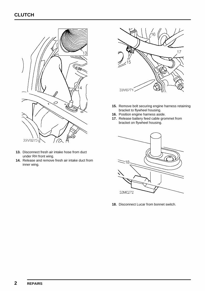
CLUTCH
2 REPAIRS
13. Disconnect fresh air intake hose from ductunder RH front wing.
14. Release and remove fresh air intake duct frominner wing.
15. Remove bolt securing engine harness retainingbracket to flywheel housing.
16. Position engine harness aside.17. Release battery feed cable grommet from
bracket on flywheel housing.
18. Disconnect Lucar from bonnet switch.

CLUTCH
REPAIRS 3
19. Remove 2 bolts securing clutch slave cylinderto mounting bracket and collect washers.
20. Withdraw slave cylinder from push rod andposition aside.
21. Remove 3 bolts securing slave cylindermounting bracket to flywheel housing.
22. Remove slave cylinder mounting bracket andcollect spacer.
23. Remove nut and bolt securing engine lowersteady bar to bracket on flywheel housing.
24. Collect steady bar washers and position aside.
25. Remove 2 nuts securing brake master cylinderto servo.
26. Release master cylinder from studs on servo.
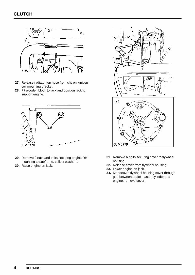
CLUTCH
4 REPAIRS
27. Release radiator top hose from clip on ignitioncoil mounting bracket.
28. Fit wooden block to jack and position jack tosupport engine.
29. Remove 2 nuts and bolts securing engine RHmounting to subframe, collect washers.
30. Raise engine on jack.
31. Remove 6 bolts securing cover to flywheelhousing.
32. Release cover from flywheel housing.33. Lower engine on jack.34. Manoeuvre flywheel housing cover through
gap between brake master cylinder andengine, remove cover.

CLUTCH
REPAIRS 5
Refit
1. Clean flywheel housing cover and mating faceof flywheel housing.
2. Manoeuvre cover through gap between brakemaster cylinder and engine.
3. Position cover to flywheel housing.4. Raise engine on jack.5. Fit and tighten bolts securing cover to flywheel
housing.6. Lower engine on jack and align engine RH
mounting to subframe.7. Fit bolts, washers and nuts securing engine
mounting to subframe.8. Remove jack supporting engine.9. Align engine lower steady bar to bracket on
flywheel housing and position washers.10. Fit bolt and nut securing engine lower steady
bar to flywheel housing bracket and tighten to40 Nm.
11. Fit brake master cylinder to studs on servo, fitnuts and tighten to 25 Nm.
12. Position clutch slave cylinder mounting bracketand spacer to flywheel housing.
13. Fit 3 bolts securing mounting bracket toflywheel housing, tighten bolts:
M8 bolts to 37 Nm.M5 bolt to 7 Nm.
14. Fit clutch slave cylinder onto push rod.15. Align slave cylinder to mounting bracket, fit
bolts and tighten to 37 Nm.16. Depress clutch pedal to load clutch lever and
remove any free play.
17. Measure clearance between throw out stoplock nut and flywheel housing cover.
18. The correct clearance is 6.5 mm. If theclearance is incorrect, loosen lock nut andadjust throw out stop to obtain correctclearance.
19. Tighten lock nut and recheck clearance.20. Secure battery feed cable grommet to bracket
on flywheel housing.21. Position engine harness retaining bracket to
flywheel housing, fit bolt and tighten to 25 Nm.22. Connect Lucar to bonnet switch.23. Position earth leads to body, fit bolt and tighten
to 9 Nm.24. Fit fresh air intake duct to inner wing.25. Connect fresh air intake hose to duct beneath
wing.26. Locate ECM mounting bracket on body, fit bolt
and tighten to 10 Nm.27. Secure clip on main harness to ECM mounting
bracket.28. Secure engine compartment fuse box to ECM
mounting bracket.29. Connect engine harness lead to engine
compartment fuse box.30. Fit fusible link.31. Fit cover to engine compartment fuse box.32. Fit engine breather/oil separator. See
EMISSION CONTROL, Repairs.33. Fit ECM. See ENGINE MANAGEMENT
SYSTEM - MEMS, Repairs.34. Fit bonnet. See BODY, Exterior fittings.35. Fit starter motor. See ELECTRICAL, Repairs.
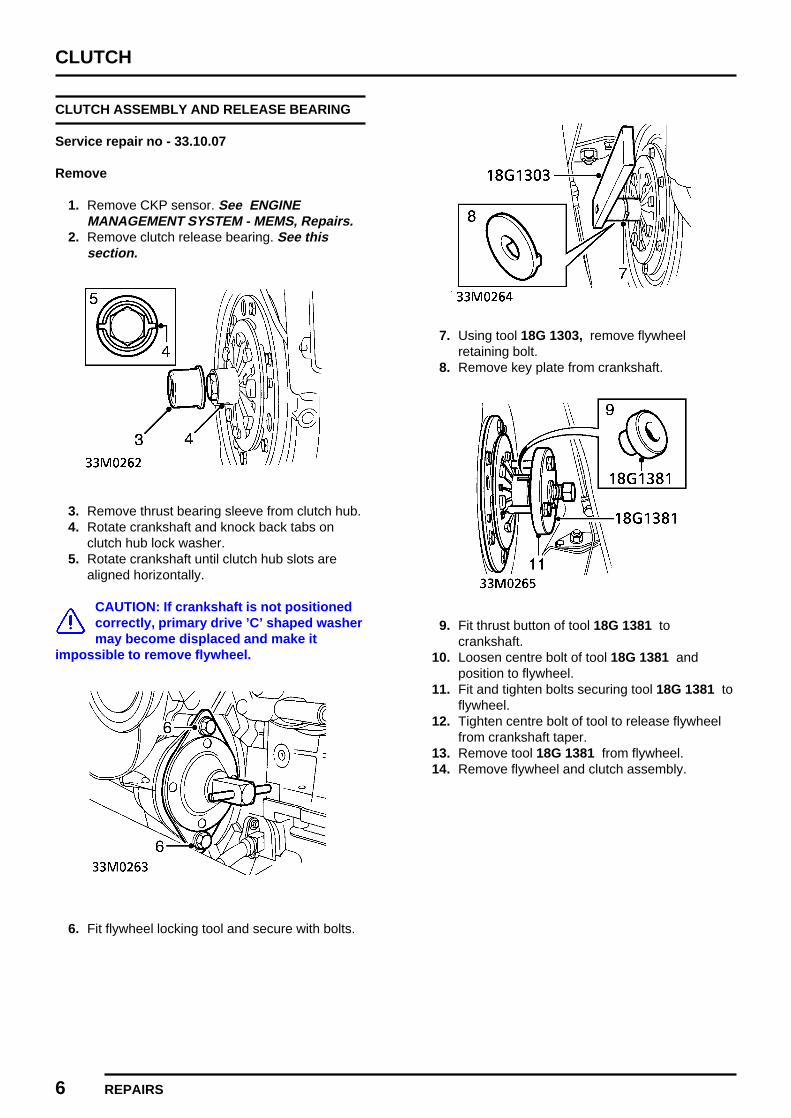
CLUTCH
6 REPAIRS
CLUTCH ASSEMBLY AND RELEASE BEARING
Service repair no - 33.10.07
Remove
1. Remove CKP sensor. See ENGINEMANAGEMENT SYSTEM - MEMS, Repairs.
2. Remove clutch release bearing. See thissection.
3. Remove thrust bearing sleeve from clutch hub.4. Rotate crankshaft and knock back tabs on
clutch hub lock washer.5. Rotate crankshaft until clutch hub slots are
aligned horizontally.
CAUTION: If crankshaft is not positionedcorrectly, primary drive ’C’ shaped washermay become displaced and make it
impossible to remove flywheel.
6. Fit flywheel locking tool and secure with bolts.
7. Using tool 18G 1303, remove flywheelretaining bolt.
8. Remove key plate from crankshaft.
9. Fit thrust button of tool 18G 1381 tocrankshaft.
10. Loosen centre bolt of tool 18G 1381 andposition to flywheel.
11. Fit and tighten bolts securing tool 18G 1381 toflywheel.
12. Tighten centre bolt of tool to release flywheelfrom crankshaft taper.
13. Remove tool 18G 1381 from flywheel.14. Remove flywheel and clutch assembly.

CLUTCH
REPAIRS 7REVISED: 12/96
15. Remove 6 bolts securing pressure plate toflywheel.
16. Remove pressure plate assembly.17. Remove drive plate from flywheel.
Refit
1. Clean flywheel and pressure plate. Checkdiaphragm spring for wear and fractures.Renew flywheel and pressure plate as anassembly if either component shows signs ofwear or damage.
2. Clean crankshaft and pressure plate hub.3. Clean inside of flywheel housing.4. Position drive plate on flywheel.5. Fit pressure plate and align to flywheel, fit bolts
but DO NOT tighten.
6. Fit clutch aligning tool 18G 684.7. Tighten pressure plate to flywheel bolts to 25
Nm.8. Remove clutch aligning tool.9. Check crankshaft primary gear end-float. See
ENGINE, Adjustments.10. Grease splines of crankshaft primary gear.11. Fit flywheel and clutch assembly to crankshaft.12. Fit keyplate and NEW flywheel retaining bolt.13. Tighten flywheel retaining bolt to 150 Nm.14. Stake lock washer into slots on clutch hub.15. Remove bolts securing flywheel locking tool to
flywheel housing.16. Remove flywheel locking tool.17. Clean thrust bearing sleeve.18. Fit thrust bearing sleeve to clutch hub.19. Fit clutch release bearing. See this section.20. Fit CKP sensor. See ENGINE
MANAGEMENT SYSTEM - MEMS, Repairs.

CLUTCH
8 REPAIRS REVISED: 12/96
RELEASE BEARING
Service repair no - 33.25.12
Remove
1. Remove flywheel housing cover. See thissection.
2. Remove ’O’ ring retaining bearing to plunger.3. Remove bearing assembly from plunger.4. Remove retainer securing locating plate to
bearing.5. Remove locating plate from bearing.
Refit
1. Clean mating face of locating plate and releasebearing.
2. Examine release bearing for signs of wear ordamage, renew if necessary.
CAUTION: Bearing is packed with grease,DO NOT eash in solvent.
3. Apply grease to plunger shaft.4. Position locating plate to bearing.5. Fit location plate retainer.6. Fit bearing assembly onto plunger.7. Fit new ’O’ ring securing bearing to plunger.8. Fit flywheel housing cover. See this section.
MASTER CYLINDER
Service repair no - 33.20.01
Remove
1. Remove ECM. See ENGINE MANAGEMENTSYSTEM - MEMS, Repairs.
2. Remove air cleaner. See ENGINEMANAGEMENT SYSTEM - MEMS, Repairs.
3. Release engine management relay modulefrom mounting bracket and position aside.
4. Release brake servo vacuum pipe from clip,move vacuum pipe and engine harness aside.

CLUTCH
REPAIRS 9ISSUED: 12/96
5. Attach bleed tube to bleed screw on slavecylinder. Remove cylinder cap and open bleedscrew, pump clutch pedal to drain fluid fromcylinder.
6. Loosen unions securing pipe to master andslave cylinders.
7. Remove clutch pipe.
CAUTION: Plug the connections.
8. Release heater air intake duct from adapterinside vehicle and remove duct.
9. Remove split pin from clutch pedal clevis pin.10. Remove clutch pedal clevis pin.
11. Remove 2 nuts securing master cylinder tobody.
12. Remove master cylinder and discard gasket.

CLUTCH
10 REPAIRS ISSUED: 12/96
Refit
1. Clean mating face of master cylinder and body.2. Fit master cylinder with new gasket to body.3. Align push rod to clutch pedal.4. Fit and tighten nuts securing master cylinder to
body.5. Lubricate and fit clevis pin securing push rod to
pedal.6. Secure clutch pedal clevis pin with a new split
pin.7. Fit fresh air intake duct to heater and connect
to adapter on body.8. Clean unions on clutch pipe, master cylinder
and slave cylinder. Fit clutch pipe and tightenunions to 14 Nm.
9. Reposition engine harness and secure brakeservo vacuum pipe to clip.
10. Secure engine management relay module tomounting bracket.
11. Bleed clutch. See Adjustments.12. Fit air cleaner. See ENGINE MANAGEMENT
SYSTEM - MEMS, Repairs.
SLAVE CYLINDER
Service repair no - 33.35.01
Remove
1. Remove ECM. See ENGINE MANAGEMENTSYSTEM - MEMS, Repairs.
2. Remove engine breather/oil separator. SeeEMISSION CONTROL, Repairs.
3. Attach bleed tube to bleed screw on slavecylinder. Remove master cylinder cap andopen bleed screw, pump clutch pedal to drainfluid from cylinder.
4. Loosen unions securing pipe to master andslave cylinder.
5. Remove clutch pipe.
CAUTION: Plug the connections.

CLUTCH
REPAIRS 11ISSUED: 12/96
6. Remove nut securing hose to bracket andremove washer.
7. Release hose from bracket.8. Remove 2 bolts securing slave cylinder to
mounting bracket.9. Withdraw slave cylinder from push rod and
remove.
Do not carry out further dismantling ifcomponent is removed for access only.
10. Holding slave cylinder in a soft jawed vice,loosen union and remove hose and sealingwashers from slave cylinder.
11. Remove old slave cylinder from vice andreplace with new.
12. Ensure mating faces of cylinder and hoseunion are clean.
13. Using new sealing washers, fit hose andtighten union.
14. Remove cylinder from vice.
Refit
1. Position slave cylinder to mounting bracket onflywheel housing, fit bolts and tighten to 37 Nm.
2. Fit hose to bracket and secure with washer andnut.
3. Clean unions on clutch pipe, master cylinderand slave cylinder.
4. Fit pipe to master cylinder and slave cylinderand tighten unions to 14 Nm.
5. Fit engine breather/oil separator. SeeEMISSION CONTROL, Repairs.
6. Bleed clutch. See Adjustments.

MANUAL GEARBOX
CONTENTS Page
ADJUSTMENTS
IDLER GEAR END-FLOAT 1.......................................................................................
REPAIRSGEAR SELECTOR MOUNTINGS 1............................................................................MANUAL GEARBOX 1................................................................................................SPEEDOMETER DRIVE GEAR 2...............................................................................SPEEDOMETER DRIVE PINION 4.............................................................................REVERSE LIGHT SWITCH 5......................................................................................

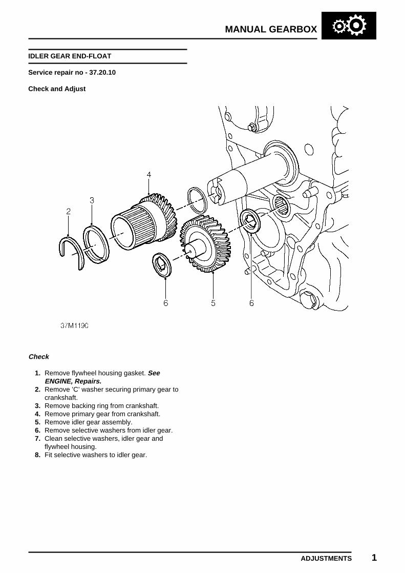
MANUAL GEARBOX
ADJUSTMENTS 1
IDLER GEAR END-FLOAT
Service repair no - 37.20.10
Check and Adjust
Check
1. Remove flywheel housing gasket. SeeENGINE, Repairs.
2. Remove ’C’ washer securing primary gear tocrankshaft.
3. Remove backing ring from crankshaft.4. Remove primary gear from crankshaft.5. Remove idler gear assembly.6. Remove selective washers from idler gear.7. Clean selective washers, idler gear and
flywheel housing.8. Fit selective washers to idler gear.

MANUAL GEARBOX
2 ADJUSTMENTS
9. Fit idler gear assembly to flywheel housing.10. Position tool 18G 1383 across flywheel
housing and idler gear, centralise tool.11. Using feeler gauges, measure gap between
tool 18G 1383 and selective washer on idlergear.DATA: End-float = 0.101 to 0.177 mm.
Adjust
12. Remove idler gear assembly from flywheelhousing.
13. Remove selective washers from idler gearassembly.
14. Select washers which will give the correctend-float figure.
15. Clean selective washers and fit to idler gear.16. Fit idler gear assembly to flywheel housing.17. Position tool 18G 1383 and centralise.18. Check that end-float is now within tolerance.
18G 1383.19. Remove idler gear assembly from flywheel
housing and fit to engine.20. Clean primary gear, backing ring and ’C’
shaped washer.21. Fit primary gear to crankshaft.22. Position backing ring on crankshaft.23. Fit ’C’ washer to crankshaft.24. Fit flywheel housing gasket. See ENGINE,
Repairs.

MANUAL GEARBOX
REPAIRS 1ISSUED: 12/96
GEAR SELECTOR MOUNTINGS
Service repair no - 37.16.25
Remove
1. Remove carpet See BODY, Interior trimcomponents.
2. Raise front of vehicle.
WARNING: Support on safety stands.
3. Remove 2 nuts securing selector mountings tofloor.
4. Lower gear selector.5. Remove nut and bolt securing mounting
bracket to gear selector and remove.6. Remove nuts securing mountings to mounting
bracket and remove mountings.
Refit
1. Position mountings to mounting bracket andsecure with nuts.
2. Position mounting bracket to gear selector,secure with nut and bolt.
3. Raise gear selector and locate mountings tofloor, fit and tighten nuts.
4. Fit carpet. See BODY, Interior trimcomponents.
5. Remove stand(s) and lower vehicle.
MANUAL GEARBOX
Service repair no - 37.20.02.99
Remove
1. The procedure for removing the gearbox isidentical to that for renewing the Engine togearbox gasket. See ENGINE, Repairs.

MANUAL GEARBOX
2 REPAIRS ISSUED: 12/96
SPEEDOMETER DRIVE GEAR
Service repair no - 37.25.01
Remove
1. Remove front pipe to manifold gasket. SeeMANIFOLD & EXHAUST SYSTEMS, Repairs.
2. Disconnect multiplug from horn.3. Remove 2 bolts securing horn to body and
remove.
4. Remove bolt securing radiator bottom hose toengine mounting.
5. Position jack to support engine.
CAUTION: Use a block of wood or hardrubber pad between jack and engine.
6. Take weight off engine mounting.7. Remove 2 bolts securing engine mounting
bracket to gearbox.8. Remove 2 bolts securing engine mounting to
subframe.9. Remove engine mounting and bracket.

MANUAL GEARBOX
REPAIRS 3ISSUED: 12/96
10. Remove 3 bolts securing engine mountingadaptor plate to gearbox. lower front bolt.
11. Loosen lower bolt securing adaptor plate togearbox.
12. Release adaptor plate from gearbox and rotateanti-clokwise to gain access to speedometerdrive gear cover plate.
NOTE: Engine may have to be raised foradaptor plate to clear crankshaft frontpully.
13. Remove 2 bolts securing drive gear cover plateto housing.
14. Remove cover plate and discard gasket.15. Remove speedometer drive gear.
Refit
1. Position speedometer drive gear in housingensuring correct engagement with mainshaftand speedometer pinion.
2. Clean mating faces of cover plate and housing.3. Position cover plate and new gasket.4. Fit bolts securing cover plate to housing and
tighten to 8 Nm.5. Position adaptor plate to gearbox and align bolt
holes.6. Fit bolts securing adaptor plate to to gearbox
and tighten to 25 Nm.7. Tighten bolt securing adaptor plate to gearbox
to 25 Nm.8. Position engine mounting and bracket.9. Lower engine to align engine mounting to
subframe.10. Fit bolts securing engine mounting to adaptor
plate and tighten to 25 Nm.11. Fit bolts securing engine mounting to subframe
and tighten to 22 Nm.12. Remove jack.13. Fit bolt securing radiator bottom hose to engine
mounting.14. Position horn to body, fit bolts and tighten to 9
Nm.15. Connect multiplug to horn.16. Fit front pipe to manifold gasket. See
MANIFOLD & EXHAUST SYSTEMS, Repairs.

MANUAL GEARBOX
4 REPAIRS ISSUED: 12/96
SPEEDOMETER DRIVE PINION
Service repair no - 37.25.05
Remove
1. Raise front of vehicle.
WARNING: Support on safety stands.
2. Disconnect battery earth lead.
3. Loosen knurled nut and disconnectspeedometer cable from housing.
4. Position speedometer cable aside.
5. Remove bolt securing drive pinion housing togearbox and remove clamping plate.
6. Remove drive pinion housing.7. Remove drive pinion from housing.8. Remove bush from drive pinion.9. Remove and discard gasket and oil seal from
housing.
Refit
1. Clean drive pinion, housing and bush.2. Lubricate inner lip of oil seal with clean engine
oil, and grease outer surface.3. Fit oil seal to housing4. Fit bush to drive pinion.5. Fit drive pinion to housing.6. Clean mating faces of drive pinion housing and
gearbox.7. Using a new gasket, fit drive pinion housing to
gearbox.8. Fit clamping plate.9. Fit bolt securing clamping plate to gearbox and
tighten to 8 Nm.10. Connect speedometer cable to gearbox and
tighten nut.11. Remove stand(s) and lower vehicle.12. Connect battery earth lead.
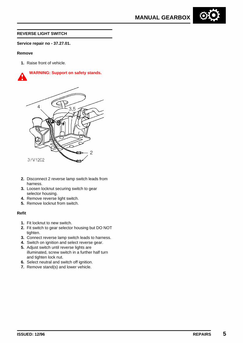
MANUAL GEARBOX
REPAIRS 5ISSUED: 12/96
REVERSE LIGHT SWITCH
Service repair no - 37.27.01.
Remove
1. Raise front of vehicle.
WARNING: Support on safety stands.
2. Disconnect 2 reverse lamp switch leads fromharness.
3. Loosen locknut securing switch to gearselector housing.
4. Remove reverse light switch.5. Remove locknut from switch.
Refit
1. Fit locknut to new switch.2. Fit switch to gear selector housing but DO NOT
tighten.3. Connect reverse lamp switch leads to harness.4. Switch on ignition and select reverse gear.5. Adjust switch until reverse lights are
illuminated, screw switch in a further half turnand tighten lock nut.
6. Select neutral and switch off ignition.7. Remove stand(s) and lower vehicle.


DRIVE SHAFTS
CONTENTS Page
REPAIRS
DRIVE SHAFT OUTER JOINT 1.................................................................................DRIVE SHAFT INNER JOINT 1...................................................................................DRIVE SHAFT AND OUTER JOINT 2.........................................................................


DRIVE SHAFTS
REPAIRS 1ISSUED: 12/96
DRIVE SHAFT OUTER JOINT
Service repair no - 47.10.04
Remove
1. Remove drive shaft and outer joint. See thissection.
2. Place drive shaft in vice.
3. Remove clip securing gaiter to outer joint.4. Fold back gaiter to gain access to outer joint.5. Using a suitable drift against the inner part of
the joint, remove joint from shaft.6. Remove circlip from shaft and discard.7. Inspect gaiter for signs of damage and renew if
necessary.
Refit
1. Thoroughly clean outer joint and drive shaft.2. Fit new circlip to drive shaft.3. Position outer joint to shaft, use a screwdriver
to press circlip into groove and push joint fullyonto shaft.
4. Apply grease from the sachet supplied to thejoint.
5. Fold back gaiter and locate on outer joint.6. Using a Band-it thrift tool secure gaiter to outer
joint with clip.7. Remove drive shaft from vice.8. Fit drive shaft and outer joint. See this
section.
DRIVE SHAFT INNER JOINT
Service repair no - 47.10.14
Remove
1. Raise front of vehicle, one side.
WARNING: Support on safety stands.
2. Remove drive shaft and outer joint, but DONOT remove drive shaft from front hub. Seethis section.
3. Position container beneath differential to collectfluid loss.
4. Using tool 18G 1240 release inner joint fromdifferential.

DRIVE SHAFTS
2 REPAIRS ISSUED: 12/96
5. Remove drive shaft inner joint.6. Remove and discard circlip from inner joint.
Refit
1. Clean drive shaft inner joint.2. Inspect differential end cover oil seal for signs
of damage and renew if necessary.3. Fit new circlip to inner joint.4. Fit inner joint to differential.
CAUTION: Ensure inner is securelyretained in differential by circlip.
5. Fit drive shaft and outer joint. See thissection.
6. Remove stand(s) and lower vehicle.7. Top-up engine oil. See
MAINTENANCEMaintenance.
DRIVE SHAFT AND OUTER JOINT
Service repair no - 47.10.28
Remove
1. Raise front of vehicle, one side.
WARNING: Support on safety stands.
2. Remove road wheel(s).
3. Remove split pin retaining drive shaft nut.4. Loosen nut securing front hub to drive shaft.

DRIVE SHAFTS
REPAIRS 3ISSUED: 12/96
5. Remove 2 bolts and collect washers securingbrake caliper to front hub.
6. Release brake caliper from front hub and tieaside.
CAUTION: Do not allow weight of caliperto hang on brake hose.
7. Raise front suspension using a jack positionedbeneath lower suspension arm.
8. Remove screw securing rebound rubber tosubframe.
9. Remove rebound rubber.10. Fit a wedge between suspension arm and
subframe, lower suspension onto wedge andremove jack.
CAUTION: Ensure that an appropriatewedge is used to prevent any damageoccurring to the suspension components.

DRIVE SHAFTS
4 REPAIRS ISSUED: 12/96
11. Remove nut securing steering rack track end tofront hub.
12. Break taper joint using tool 18G 1584.13. Disconnect track rod end from front hub.
14. Remove nut and washer securing front hubupper ball joint to suspension arm.
15. Break taper joint using tool 18G 1584.
CAUTION: Be careful not to damage therubber boot on ball joint.
16. Remove nut and washer securing front hublower ball joint to suspension arm.
17. Break taper joint using tool 18G 1584.18. Loosely fit nut securing upper ball joint to
suspension arm.

DRIVE SHAFTS
REPAIRS 5ISSUED: 12/96
19. Using a suitable drift, release drive shaft frominner joint.
CAUTION: Take care not to damage gaiteron drive shaft inner joint.
20. Remove nut and disconnect front hub fromupper suspension arm.
21. Retain position of inboard joint gaiter andremove drive shaft and hub as an assembly.
22. Remove hub nut and split collar securing fronthub to drive shaft. Withdraw drive shaft fromhub.
Do not carry out further dismantling ifcomponent is removed for access only.
23. Remove hub bearing water shield.

DRIVE SHAFTS
6 REPAIRS ISSUED: 12/96
Refit
1. Clean both ends of drive shaft.
2. Fit hub bearing water shield onto drive shaft asshown:’A’ = 6 mm approximately.
3. Lubricate end of drive shaft and fit to inboardjoint.
NOTE: Ensure shaft is securely retainedby joint.
4. Clean front hub ball joints and mating faces ofsuspension arms.
5. Fit front hub to drive shaft and engage upperand lower ball joints on suspension arms.
6. Fit nuts and washers securing suspensionarms to front hub and tighten to 52 Nm.
7. Connect steering rack track rod end to fronthub, fit nut and tighten to 30 Nm.
8. Clean front brake disc.9. Fit brake caliper to front hub.
10. Fit 2 bolts and washers securing brake caliperto front hub and tighten to 52 Nm.
11. Fit road wheel.12. Position jack beneath lower suspension arm
and raise front suspension.13. Remove wedge between suspension arm and
subframe.14. Position rebound rubber and secure with
screw.15. Remove jack from beneath suspension arm.16. Remove stand(s) and lower vehicle.17. Fit split collar and tighten hub nut to 260 Nm.18. Align nut to next split pin hole and fit new split
pin.

STEERING
CONTENTS Page
ADJUSTMENTS
FRONT WHEEL ALIGNMENT 1..................................................................................
REPAIRSSTEERING RACK AND PINION 1...............................................................................STEERING COLUMN NACELLE 5..............................................................................STEERING COLUMN LOCK 6....................................................................................STEERING COLUMN ASSEMBLY 8...........................................................................STEERING WHEEL 11................................................................................................


STEERING
ADJUSTMENTS 1
FRONT WHEEL ALIGNMENT
Service repair no - 57.65.01
Check
1. Ensure tyre pressures are correct and vehicleis at kerbside weight.
2. With the wheels in the straight ahead position,roll vehicle backwards and forwards at least avehicle length to relieve any stresses in thesteering and suspension.
3. Release carpet from LH foot well to accessgrommet, remove grommet from floor.
4. Using an Allen key, remove plug from steeringrack.
5. Using assistance, move road wheels until a6mm diameter rod can be inserted into thecentralising hole in the steering rack.
6. Ensure that equipment is properly calibratedand take an average of 3 readings.
NOTE: Only use equipment recommendedin the STEP (Service Tools and EquipmentProgramme) Manual.
7. Check front wheel alignment is withintolerance.
DATA: Front wheel alignment.= Toe out 0° 15" ± 7.5" per side
Adjust
1. Mark position of track rod ends for reference.
2. Loosen track rod end locknuts.3. Loosen clip securing gaiter to the track rod.4. Rotate track rod to obtain correct alignment.
CAUTION: Both track rod ends must berotated an equal amount.
5. Recheck front wheel alignment and adjust ifnecessary.
6. Tighten track rod end locknuts to 52 Nm.7. Ensure gaiters are not strained or twisted then
tighten clip.8. Remove 6mm rod from steering rack, fit and
tighten blanking plug.9. Fit grommet to floor and reposition carpet.


STEERING
REPAIRS 1
STEERING RACK AND PINION
Service repair no - 57.25.01
Remove
WARNING: SRS procedures must befollowed and all precautions observed.See RESTRAINT SYSTEMS, Precautions.
1. Raise front of vehicle.
WARNING: Support on safety stands.
2. Remove both front road wheels.3. Remove air cleaner. See ENGINE
MANAGEMENT SYSTEM - MEMS, Repairs.4. Remove steering column nacelle. See this
section.
5. Disconnect 2 multiplugs fromindicator/headlamp switch.
6. Disconnect multiplug from windscreen washerand wiper switch.
7. Disconnect multiplug from rotary coupler.
8. Disconnect multiplug from ignition/starterswitch.
9. Release carpet from around steering column.

STEERING
2 REPAIRS
10. Remove bolt securing steering column tosteering rack pinion.
11. Remove bolt securing steering column tosupport bracket.
12. Remove steering column assembly.
13. Remove nuts securing steering rack track endsto front hubs.
14. Break taper joints using tool 18G 1584.15. Disconnect track rod ends from front hubs.
16. Remove nuts and bolts securing front dampersto suspension upper arms, collect spacers andwashers.

STEERING
REPAIRS 3
17. Remove 4 nuts and bolts securing frontsubframe to mounting brackets on body, collectwashers. 18. Remove 2 bolts securing emission canister
purge valve to body.19. Position purge valve aside.20. Fit wooden block or hard rubber pad to jack
and position jack to support rear of frontsubframe.
21. Remove 2 bolts securing subframe turrets tobody.
22. Lower subframe to give a clearance ofapproximately 20 mm between the subframeturrets and body.
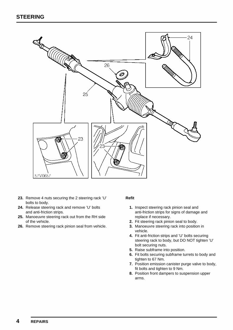
STEERING
4 REPAIRS
23. Remove 4 nuts securing the 2 steering rack ’U’bolts to body.
24. Release steering rack and remove ’U’ boltsand anti-friction strips.
25. Manoeuvre steering rack out from the RH sideof the vehicle.
26. Remove steering rack pinion seal from vehicle.
Refit
1. Inspect steering rack pinion seal andanti-friction strips for signs of damage andreplace if necessary.
2. Fit steering rack pinion seal to body.3. Manoeuvre steering rack into position in
vehicle.4. Fit anti-friction strips and ’U’ bolts securing
steering rack to body, but DO NOT tighten ’U’bolt securing nuts.
5. Raise subframe into position.6. Fit bolts securing subframe turrets to body and
tighten to 67 Nm.7. Position emission canister purge valve to body,
fit bolts and tighten to 9 Nm.8. Position front dampers to suspension upper
arms.

STEERING
REPAIRS 5
9. Fit spacers, washers, nuts and bolts securingfront dampers to suspension upper arms,tighten nuts to 48 Nm.
10. Align subframe to mounting brackets on body.11. Fit nuts, bolts and washers securing subframe
to mounting bracket and tighten nuts to 25 Nm.12. Connect steering rack track rod ends to front
hubs, fit nuts and tighten to 30 Nm.13. Release carpet from LH foot well to access
grommet, remove grommet from floor.14. Using an Allen key, remove plug from steering
rack.15. Using assistance, move road wheels until a
6mm diameter rod can be inserted into thecentralising hole in the steering rack.
16. Fit steering column assembly to steering rackpinion.
17. Fit pinch bolt securing column to pinion andtighten to 15 Nm.
18. Tighten nuts securing steering rack ’U’ bolts tobody, to 15 Nm.
19. Reposition carpet round steering column.20. Align steering column to mounting bracket, fit
bolt and tighten to 25 Nm.21. Connect multiplugs to column switches and
ignition/starter switch.22. Connect multiplug from rotary coupler.23. Fit steering column nacelle. See this section.24. Fit air cleaner. See ENGINE MANAGEMENT
SYSTEM - MEMS, Repairs.25. Fit road wheels.26. Remove stand(s) and lower vehicle.27. Remove 6 mm rod from steering rack, fit and
tighten blanking plug.28. Fit grommet to floor and reposition carpet.
STEERING COLUMN NACELLE
Service repair no - 57.40.29
Remove
1. Remove 3 screws securing steering columnnacelle.
2. Separate and remove upper and lower halvesof nacelle.
CAUTION: Care must be taken whenremoving upper half of nacelle to avoiddamaging the steering wheel.
Refit
1. Fit upper and lower half of column nacelle andfasten together.
2. Align nacelle to bracket on column and securewith screws.

STEERING
6 REPAIRS
STEERING COLUMN LOCK
Service repair no - 57.40.31
Remove
WARNING: SRS procedures must befollowed and all precautions observed.See RESTRAINT SYSTEMS, Precautions.
1. Remove steering column nacelle. See thissection.
2. Disconnect 2 multiplugs fromindicator/headlamp switch.
3. Disconnect multiplug from windscreen washerand wiper switch.
4. Disconnect multiplug from ignition/starterswitch.
5. Disconnect 2 multiplugs from rotary coupler.6. Release carpet from around steering column.
7. Remove bolt securing steering column tosteering rack.

STEERING
REPAIRS 7
8. Remove bolt securing steering column tosupport bracket.
9. Remove steering column assembly.10. Position steering column in vice.11. Centre punch shear bolts securing lock to
column.
12. Using a 5mm drill, drill out 2 shear boltssecuring column to lock.
CAUTION: Take care not to damage lockbody if lock is to be refitted.
13. Remove steering column lock.
Refit
1. Locate steering column lock in position onsteering column, fit but do not tighten shearbolts.
2. Insert key, confirm correct operation of steeringlock and that key turns freely.
3. Tighten shear bolts until heads shear off.4. Remove steering column assembly from vice.
5. Release carpet from LH foot well to accessgrommet, remove grommet from floor.
6. Using an Allen key, remove plug from steeringrack.
7. Using assistance, move road wheels until a6mm diameter rod can be inserted into thecentralising hole in the steering rack.
8. Fit steering column assembly to steering rackpinion.
9. Fit pinch bolt securing column to pinion andtighten to 15 Nm.
10. Reposition carpet round steering column.

STEERING
8 REPAIRS
11. Align steering column to mounting bracket, fitbolt and tighten to 25 Nm.
12. Connect multiplugs to column switches andignition/starter switch.
13. Connect 2 multiplugs to rotary coupler.14. Fit steering column nacelle. See this section.15. Remove 6mm rod from steering rack, fit and
tighten blanking plug.16. Fit grommet to floor and reposition carpet.17. Connect battery earth lead.18. Carry out system check by turning the ignition
on and checking that the SRS warning lightilluminates then extinguishes after 3 seconds.
STEERING COLUMN ASSEMBLY
Service repair no - 57.50.01
Remove
1. Disconnect battery earth lead.2. Remove rotary coupler. See ELECTRICAL,
Repairs.
3. Disconnect 2 multiplugs fromindicator/headlamp switch.

STEERING
REPAIRS 9
4. Disconnect multiplug from windscreen washerand wiper switch.
5. Remove 2 screws securing column switchassembly to steering column.
6. Remove steering column switch assembly.
7. Disconnect multiplug from ignition/starterswitch.
8. Release carpet from around steering column.
9. Remove bolt securing steering column tosteering rack pinion.
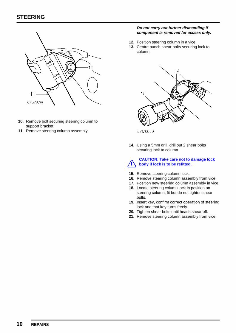
STEERING
10 REPAIRS
10. Remove bolt securing steering column tosupport bracket.
11. Remove steering column assembly.
Do not carry out further dismantling ifcomponent is removed for access only.
12. Position steering column in a vice.13. Centre punch shear bolts securing lock to
column.
14. Using a 5mm drill, drill out 2 shear boltssecuring lock to column.
CAUTION: Take care not to damage lockbody if lock is to be refitted.
15. Remove steering column lock.16. Remove steering column assembly from vice.17. Position new steering column assembly in vice.18. Locate steering column lock in position on
steering column, fit but do not tighten shearbolts.
19. Insert key, confirm correct operation of steeringlock and that key turns freely.
20. Tighten shear bolts until heads shear off.21. Remove steering column assembly from vice.

STEERING
REPAIRS 11
Refit
1. Release carpet from LH foot well to accessgrommet, remove grommet from floor.
2. Using an Allen key, remove plug from steeringrack.
3. Using assistance, move road wheels until a6mm diameter rod can be inserted into thecentralising hole in the steering rack.
4. Fit steering column assembly to steering rackpinion.
5. Fit pinch bolt securing column to pinion andtighten to 15 Nm.
6. Reposition carpet round steering column.7. Align steering column to mounting bracket, fit
bolt and tighten to 25 Nm.8. Fit steering column switch assembly and
secure with screws.9. Connect multiplugs to column switches and
ignition/starter switch.10. Fit rotary coupler. See ELECTRICAL,
Repairs.11. Remove 6 mm rod from steering rack, fit and
tighten blanking plug.12. Fit grommet to floor and reposition carpet.
STEERING WHEEL
Service repair no - 57.60.01
Remove
1. Remove driver’s airbag module. SeeRESTRAINT SYSTEMS, Repairs.
2. Disconnect horn multiplug from rotary coupling.3. Centralise steering wheel with road wheels in
straight ahead position.4. Restrain steering wheel and loosen self-locking
nut securing steering wheel to column. Loosen2 turns only.
5. Release steering wheel from column splines byrocking steering wheel from side-to-side andpulling with both hands.
6. Remove and discard self-locking nut.7. Remove steering wheel.

STEERING
12 REPAIRS
8. Attach tape across edge of rotary coupler toretain in central setting.
Do not carry out further dismantling ifcomponent is removed for access only.
9. Release horn switches from steering wheel.10. Disconnect Lucar connections from switches
and remove switches.11. Remove horn harness from steering wheel.
Refit
1. Fit horn harness to steering wheel.2. Position horn switches to wheel, connect
Lucars and fit switches.3. Remove retaining tape from rotory coupler.4. Ensure road wheels are in straight ahead
position and indicator cancel cam alignedvertical.
5. Engauge rotory coupling and fit steering wheelto column, ensure wheel spokes are horizontal.
6. Fit NEW self-locking nut, and tighten to 49 Nm.7. Connect horn multiplug to rotary coupler.8. Fit driver’s airbag module. See RESTRAINT
SYSTEMS, Repairs.

SUSPENSION
CONTENTS Page
ADJUSTMENTS
DAMPER ADJUSTMENT 1.........................................................................................
REPAIRSFRONT BUMP RUBBER 1..........................................................................................FRONT REBOUND RUBBER 1...................................................................................FRONT DAMPER 2.....................................................................................................REAR DAMPER 3........................................................................................................

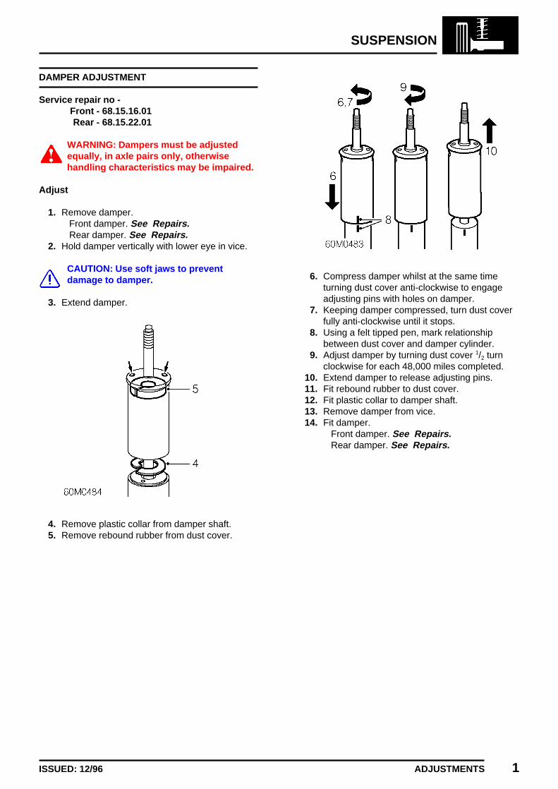
SUSPENSION
ADJUSTMENTS 1ISSUED: 12/96
DAMPER ADJUSTMENT
Service repair no -Front - 68.15.16.01Rear - 68.15.22.01
WARNING: Dampers must be adjustedequally, in axle pairs only, otherwisehandling characteristics may be impaired.
Adjust
1. Remove damper.Front damper. See Repairs.Rear damper. See Repairs.
2. Hold damper vertically with lower eye in vice.
CAUTION: Use soft jaws to preventdamage to damper.
3. Extend damper.
4. Remove plastic collar from damper shaft.5. Remove rebound rubber from dust cover.
6. Compress damper whilst at the same timeturning dust cover anti-clockwise to engageadjusting pins with holes on damper.
7. Keeping damper compressed, turn dust coverfully anti-clockwise until it stops.
8. Using a felt tipped pen, mark relationshipbetween dust cover and damper cylinder.
9. Adjust damper by turning dust cover 1/2 turnclockwise for each 48,000 miles completed.
10. Extend damper to release adjusting pins.11. Fit rebound rubber to dust cover.12. Fit plastic collar to damper shaft.13. Remove damper from vice.14. Fit damper.
Front damper. See Repairs.Rear damper. See Repairs.


SUSPENSION
REPAIRS 1ISSUED: 12/96
FRONT BUMP RUBBER
Service repair no - 68.15.01
Remove
1. Raise front of vehicle, one side.
WARNING: Support on safety stands.
2. Remove road wheel(s).
3. Using an 11mm spanner remove nut securingbump rubber to subframe.
4. Remove bump rubber and collect spacer.
Refit
1. Fit spacer, position bump rubber to subframe.2. Fit and tighten nut securing bump rubber to
subframe.3. Fit road wheel and tighten nuts.4. Remove stand(s) and lower vehicle.
FRONT REBOUND RUBBER
Service repair no - 68.15.08
Remove
1. Raise front of vehicle, one side.
WARNING: Support on safety stands.
2. Remove road wheel(s).3. Raise front suspension using a jack positioned
beneath lower suspension arm.
4. Remove screw securing rebound rubber tosubframe.
5. Remove rebound rubber.
Refit
1. Position rebound rubber and secure withscrew.
2. Remove jack from beneath suspension arm.3. Fit road wheel and tighten nuts4. Remove stand(s) and lower vehicle.

SUSPENSION
2 REPAIRS ISSUED: 12/96
FRONT DAMPER
Service repair no - 68.15.16
Remove
1. Raise front of vehicle, one side.
WARNING: Support on safety stands.
2. Remove road wheel(s).
3. Remove nut and washers securing damper tobracket on body.
4. Remove nut and washers securing damper tosuspension upper arm and remove spacer.
5. Remove front damper.
NOTE: Store damper upright if it is to berefitted.
Refit
1. Hold new damper in vice, compress andextend it through its full stroke until there is nofree travel when changing direction of stroke.
2. Fit spacer and washer to suspension upperarm bolt.
3. Fit washer to bolt on body and locate damperon mounting bolts.
4. Fit nut and washer securing damper to bracketon body and tighten to 37 Nm.
5. Fit nut and washer securing damper tosuspension upper arm and tighten to 48 Nm.
6. Fit road wheel and tighten nuts.7. Remove stand(s) and lower vehicle.
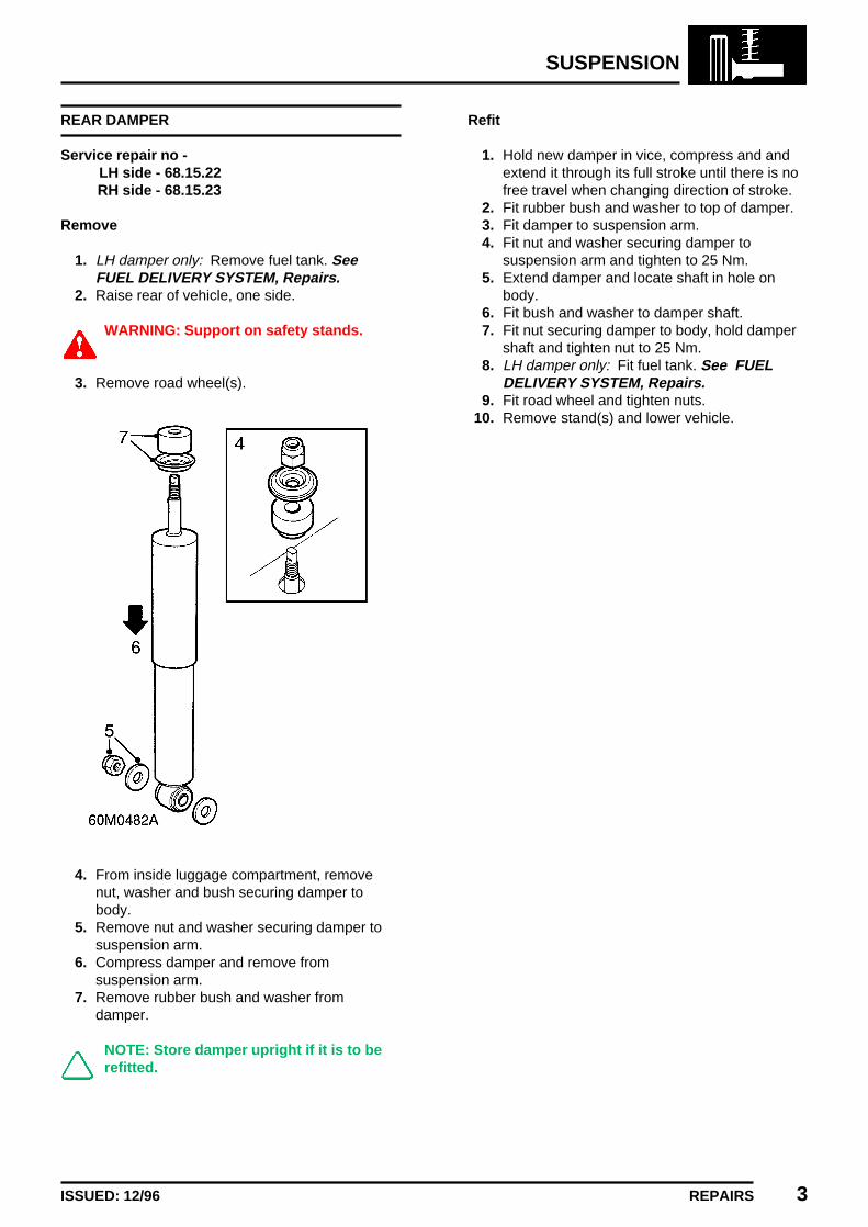
SUSPENSION
REPAIRS 3ISSUED: 12/96
REAR DAMPER
Service repair no -LH side - 68.15.22RH side - 68.15.23
Remove
1. LH damper only: Remove fuel tank. SeeFUEL DELIVERY SYSTEM, Repairs.
2. Raise rear of vehicle, one side.
WARNING: Support on safety stands.
3. Remove road wheel(s).
4. From inside luggage compartment, removenut, washer and bush securing damper tobody.
5. Remove nut and washer securing damper tosuspension arm.
6. Compress damper and remove fromsuspension arm.
7. Remove rubber bush and washer fromdamper.
NOTE: Store damper upright if it is to berefitted.
Refit
1. Hold new damper in vice, compress and andextend it through its full stroke until there is nofree travel when changing direction of stroke.
2. Fit rubber bush and washer to top of damper.3. Fit damper to suspension arm.4. Fit nut and washer securing damper to
suspension arm and tighten to 25 Nm.5. Extend damper and locate shaft in hole on
body.6. Fit bush and washer to damper shaft.7. Fit nut securing damper to body, hold damper
shaft and tighten nut to 25 Nm.8. LH damper only: Fit fuel tank. See FUEL
DELIVERY SYSTEM, Repairs.9. Fit road wheel and tighten nuts.
10. Remove stand(s) and lower vehicle.


BRAKES
CONTENTS Page
ADJUSTMENTS
BRAKE SYSTEM BLEED 1.........................................................................................BRAKE LIGHT SWITCH 2...........................................................................................
REPAIRSREAR BRAKE DRUM 1...............................................................................................BRAKE FAILURE WARNING SWITCH 2....................................................................PRESSURE REDUCING VALVE 3.............................................................................BRAKE LIGHT SWITCH 5...........................................................................................MASTER CYLINDER 5................................................................................................BRAKE PEDAL 7.........................................................................................................FRONT BRAKE PADS 9..............................................................................................REAR BRAKE SHOES 10...........................................................................................SERVO ASSEMBLY 12...............................................................................................FRONT BRAKE CALIPER 14......................................................................................REAR WHEEL BRAKE CYLINDER 15........................................................................HANDBRAKE CABLE - FRONT 15.............................................................................


BRAKES
ADJUSTMENTS 1REVISED: 12/96
BRAKE SYSTEM BLEED
Service repair no - 70.25.02
The following procedure covers bleeding thecomplete system but where only the primary orsecondary circuit have been disturbed in isolation, itshould only be necessary to bleed that system.Partial bleeding of the hydraulic system is onlypermissable if a brake pipe or hose has beendisconnected with only minor loss of fluid.
CAUTION: Never reuse fluid that has beenbled from the brake system. Do not allowfluid level in master cylinder to fall below
’MIN’ mark during bleeding. Do not fill reservoirabove ’MAX’ mark.
CAUTION: Do not allow brake fluid tocontact paint finished surfaces as paintmay be damaged. If spilled, remove fluid
and clean area with clean warm water.
Bleed
1. Raise front and rear of vehicle.
WARNING: Support on safety stands.
2. Check all pipe and hose connections are tightand there are no signs of leakage.
3. Top-up fluid level in brake reservoir to ’MAX’mark. See INFORMATION, Capacities, fluidsand lubricants.
CAUTION: Use only new brake fluid of therecommended grade.
4. Attach bleed tube to front brake caliper bleedscrew (A), submerge free end in a clearcontainer containing brake fluid.
NOTE: Bleed brakes with handbrake inOFF position.
5. Apply pressure to brake pedal several times,then apply steady pressure.
6. Loosen bleed screw to release brake fluid andair.
7. Depress brake pedal steadily through its fullstroke and allow to return unassisted. Repeatprocedure until a flow of clean air-free fluid ispurged into container then, whilst holding pedalat end of downward stroke, tighten bleed screwto 9 Nm.
CAUTION: Maintain brake fluid level above’MIN’ mark during this procedure.
8. Top-up brake fluid level.9. Repeat procedure at each wheel in the
sequence shown.
CAUTION: Braking efficiency may beseriously impaired if wrong bleedsequence is used.
10. Remove bleed tube. Apply brakes and checkfor leakage.
11. Remove stand(s) and lower vehicle.12. Road test vehicle. Check brake pedal for short
firm travel when brakes are applied.
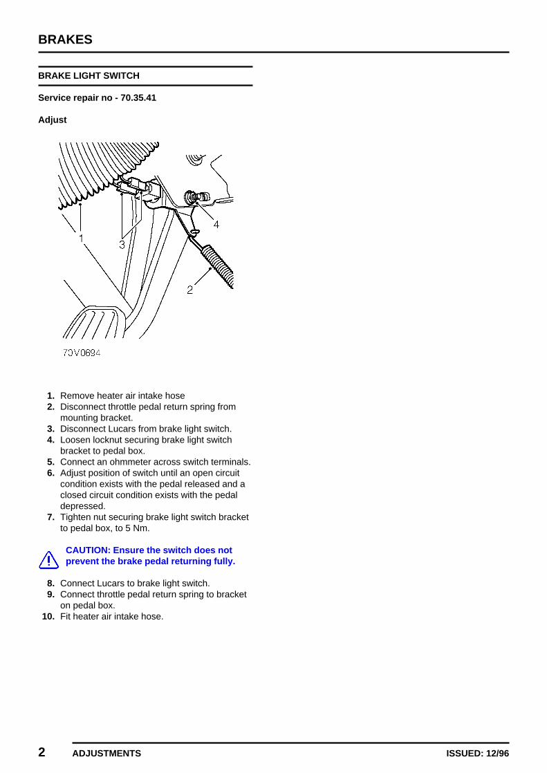
BRAKES
2 ADJUSTMENTS ISSUED: 12/96
BRAKE LIGHT SWITCH
Service repair no - 70.35.41
Adjust
1. Remove heater air intake hose2. Disconnect throttle pedal return spring from
mounting bracket.3. Disconnect Lucars from brake light switch.4. Loosen locknut securing brake light switch
bracket to pedal box.5. Connect an ohmmeter across switch terminals.6. Adjust position of switch until an open circuit
condition exists with the pedal released and aclosed circuit condition exists with the pedaldepressed.
7. Tighten nut securing brake light switch bracketto pedal box, to 5 Nm.
CAUTION: Ensure the switch does notprevent the brake pedal returning fully.
8. Connect Lucars to brake light switch.9. Connect throttle pedal return spring to bracket
on pedal box.10. Fit heater air intake hose.

BRAKES
REPAIRS 1REVISED: 12/96
REAR BRAKE DRUM
Service repair no - 70.10.03
Remove
1. Raise rear of vehicle.
WARNING: Support on safety stands.
2. Remove road wheel(s).3. Release handbrake.
4. Remove wheel spacer from rear hub.5. Remove screw securing brake drum to hub.6. Loosen brake shoe adjuster.7. Withdraw brake drum from hub.
Inspect
1. Clean backplate and brake drum with brakecleaning fluid.
WARNING: Do not use an air line to blowdust from brake assembly.Do not use petroleum based fluid as
damage will occur to rubber components.
2. Renew brake drum if scored, grooved orcracked.
3. Measure inside diameter of drum at 2 points.Drum internal diameter:New = 177.75 - 177.85 mmService limit = 179 mmDrum ovality limit = 0.012 mmRenew drum if outside limits.
4. Examine wheel cylinder dust seals for signs ofbrake fluid leakage, a certain amount ofdampness is usual. However, if free fluid isapparent, lift dust seal and check for excessiveleakage.Renew wheel cylinder if brake linings havebecome contaminated.
5. Check wheel cylinder pistons for freedom ofmovement.
Refit
1. Apply Molycote 111 grease to brake shoe andspring contact points.
2. Fit brake drum, tighten screw to 7 Nm.
NOTE: Clean inside of NEW brake drumwith brake cleaning fluid.
3. Fit wheel spacer to rear hub.4. Fit road wheel and tighten nuts.5. Remove stand(s) and lower vehicle.6. Adjust rear brakes. See
MAINTENANCEMaintenance.
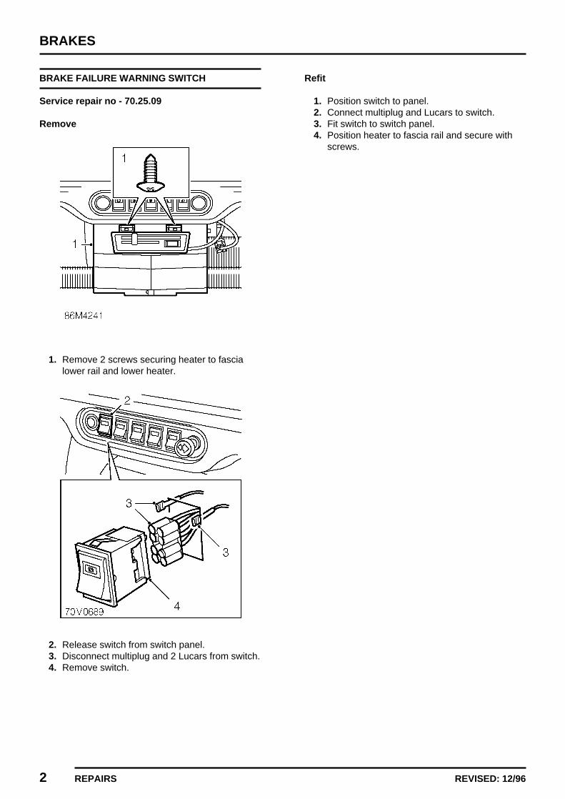
BRAKES
2 REPAIRS REVISED: 12/96
BRAKE FAILURE WARNING SWITCH
Service repair no - 70.25.09
Remove
1. Remove 2 screws securing heater to fascialower rail and lower heater.
2. Release switch from switch panel.3. Disconnect multiplug and 2 Lucars from switch.4. Remove switch.
Refit
1. Position switch to panel.2. Connect multiplug and Lucars to switch.3. Fit switch to switch panel.4. Position heater to fascia rail and secure with
screws.
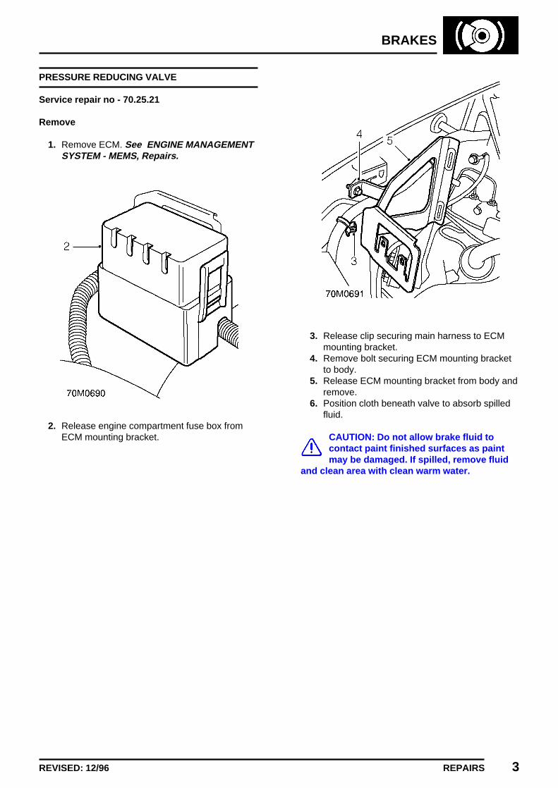
BRAKES
REPAIRS 3REVISED: 12/96
PRESSURE REDUCING VALVE
Service repair no - 70.25.21
Remove
1. Remove ECM. See ENGINE MANAGEMENTSYSTEM - MEMS, Repairs.
2. Release engine compartment fuse box fromECM mounting bracket.
3. Release clip securing main harness to ECMmounting bracket.
4. Remove bolt securing ECM mounting bracketto body.
5. Release ECM mounting bracket from body andremove.
6. Position cloth beneath valve to absorb spilledfluid.
CAUTION: Do not allow brake fluid tocontact paint finished surfaces as paintmay be damaged. If spilled, remove fluid
and clean area with clean warm water.

BRAKES
4 REPAIRS REVISED: 12/96
7. Loosen unions and disconnect lower brakepipes from valve
CAUTION: Plug the connections.
8. Position cloth under master cylinder to absorbspilled fluid.
9. Loosen unions and disconnect brake pipesfrom master cylinder.
CAUTION: Plug the connections.
10. Remove bolt securing valve to body.11. Remove valve and pipes as an assembly.12. Loosen unions and remove pipes from
pressure reducing valve.
Refit
1. Remove blanking plugs from new valve.2. Clean master cylinder brake pipe and pressure
reducing valve unions.3. Fit pipes to valve and tighten unions. 14 Nm.4. Position valve and pipe assembly to body, fit
bolt and tighten to 17 Nm.5. Remove plugs from master cylinder.6. Clean master cylinder and brake pipe unions.7. Connect pipes to master cylinder and tighten
unions to 14 Nm.8. Connect brake pipes to valve and tighten
unions to 14 Nm.9. Remove cloth positioned to absorb fluid.
10. Locate ECM mounting bracket on body, fit boltand tighten to 10 Nm.
11. Secure clip on main harness to ECM mountingbracket.
12. Secure engine compartment fuse box to ECMmounting bracket.
13. Fit ECM. See ENGINE MANAGEMENTSYSTEM - MEMS, Repairs.
14. Bleed brakes. See Adjustments.

BRAKES
REPAIRS 5ISSUED: 12/96
BRAKE LIGHT SWITCH
Service repair no - 70.35.42
Remove
1. Remove heater air intake hose.2. Disconnect Lucars from brake light switch.3. Loosen locknut securing brake light switch to
pedal box bracket and remove switch
Refit
1. Fit brake light switch and tighten locknut.2. Adjust brake light switch. See Adjustments.
MASTER CYLINDER
Service repair no - 70.30.08
Remove
1. Disconnect 2 Lucars from fluid reservoir fillercap.
2. Position cloth under master cylinder to absorbspilled fluid.
CAUTION: Do not allow brake fluid tocontact paint finished surfaces as paintmay be damaged. If spilled, remove fluid
and clean area with clean warm water.
3. Loosen union and disconnect secondarysystem pipe from master cylinder.
4. Loosen union and disconnect primary systempipe from master cylinder.
5. Move brake pipes aside.6. Remove 2 nuts securing master cylinder to
servo.7. Remove master cylinder.8. Remove and discard ’O’ ring from master
cylinder.

BRAKES
6 REPAIRS ISSUED: 12/96
Do not carry out further dismantling ifcomponent is removed for access only.
9. Using a suitably sized, flat ended punch, driveout roll pin securing reservoir to cylinder body.
10. Remove reservoir from master cylinder.11. Remove 2 sealing washers from reservoir.12. Extract 2 metal seating washers from master
cylinder.13. Clean 2 metal seating washers and fit to
master cylinder.14. Lubricate 2 new sealing washers with clean
brake fluid and fit to reservoir.15. Fit reservoir to master cylinder and secure with
new roll pin.
Refit
1. Lubricate new ’O’ ring with clean brake fluidand fit to master cylinder.
2. Clean mating faces of master cylinder andbrake servo.
3. Clean brake servo push rod and lubricate.4. Locate master cylinder on servo ensuring push
rod is correctly seated.5. Fit nuts securing master cylinder to servo and
tighten to 25 Nm.6. Remove plugs from master cylinder and brake
pipes.7. Clean brake pipe unions.8. Connect brake pipes to master cylinder and
tighten unions to 14 Nm.9. Connect Lucars to fluid reservoir filler cap.
10. Bleed brake system. See Adjustments.
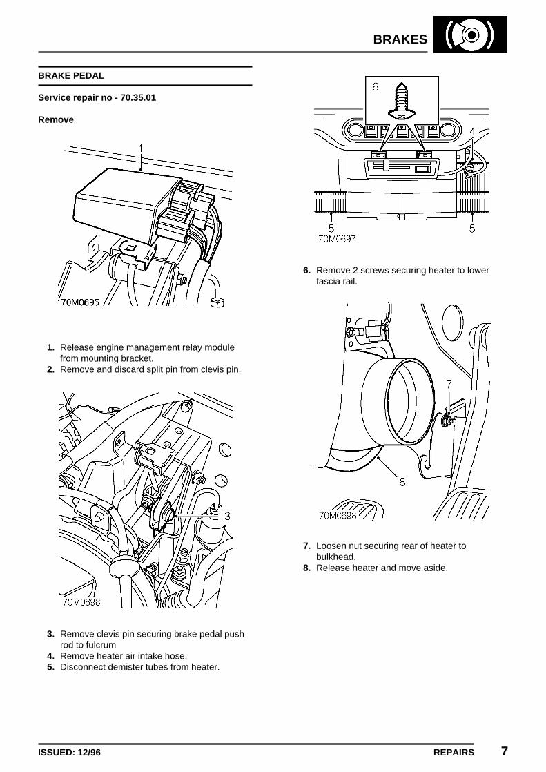
BRAKES
REPAIRS 7ISSUED: 12/96
BRAKE PEDAL
Service repair no - 70.35.01
Remove
1. Release engine management relay modulefrom mounting bracket.
2. Remove and discard split pin from clevis pin.
3. Remove clevis pin securing brake pedal pushrod to fulcrum
4. Remove heater air intake hose.5. Disconnect demister tubes from heater.
6. Remove 2 screws securing heater to lowerfascia rail.
7. Loosen nut securing rear of heater tobulkhead.
8. Release heater and move aside.
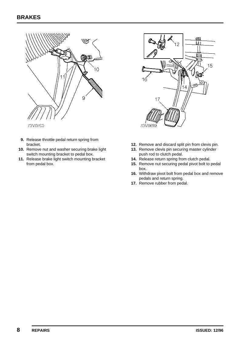
BRAKES
8 REPAIRS ISSUED: 12/96
9. Release throttle pedal return spring frombracket.
10. Remove nut and washer securing brake lightswitch mounting bracket to pedal box.
11. Release brake light switch mounting bracketfrom pedal box.
12. Remove and discard split pin from clevis pin.13. Remove clevis pin securing master cylinder
push rod to clutch pedal.14. Release return spring from clutch pedal.15. Remove nut securing pedal pivot bolt to pedal
box.16. Withdraw pivot bolt from pedal box and remove
pedals and return spring.17. Remove rubber from pedal.

BRAKES
REPAIRS 9ISSUED: 12/96
Refit
1. Fit rubber to pedal.2. Clean pedal bushes and pivot bolt.3. Lubricate pedal pivot bolt.4. Position pedals and return spring to pedal box .5. Align push rods to pedals, fit pedal pivot bolt.
NOTE: Ensure pivot bolt is correctlylocated.
6. Fit nut securing pivot bolt to pedal box andtighten to 15 Nm.
7. Clean and lubricate clutch master cylinderclevis pin.
8. Align clutch master cylinder push rod to pedal,fit clevis pin and secure with new split pin.
9. Connect return spring to clutch pedal.10. Position brake light switch mounting bracket to
pedal box, fit nut and tighten to 5 Nm.11. Secure throttle pedal return spring to mounting
bracket.12. Locate heater on bulkhead.13. Tighten nut securing heater to bulkhead to 9
Nm.14. Fit and tighten screws securing front of heater
to lower fascia rail.15. Connect demister tubes to heater.16. Fit heater air intake hose.17. Align brake pedal push rod to fulcrum, fit clevis
pin and secure with NEW split pin.18. Secure engine management relay module to
mounting bracket.19. Adjust brake light switch. See Adjustments.
FRONT BRAKE PADS
Service repair no - 70.40.02
Remove
1. Raise front of vehicle.
WARNING: Support on safety stands.
2. Remove road wheel(s).
WARNING: Brake pads must be renewedin axle sets only. Braking efficiency mayouterwise be impaired.
3. Remove 2 split pins retaining brake pads.4. Remove brake pad anti-rattle spring.5. Remove 2 brake pads.

BRAKES
10 REPAIRS ISSUED: 12/96
Refit
1. Rotate disc by hand and scrape all scale andrust from around edge of disc.
2. Scrape rust from pad locating surfaces oncaliper.
3. Clean dust from calipers using brake cleaningfluid or industrial alcohol.
WARNING: Do not use an air line to blowdust from brake assembly. Do not usepetroleum based fluid as damage will
occur to rubber components.
4. Position bleed bottle, connect bleed hose tobleed screw and loosen screw.
5. Press piston back into housing.6. Tighten bleed screw to 9 Nm.7. Remove bleed bottle.8. Fit brake pads to caliper.
NOTE: Fit pad with wear indicator on theinside.
9. Position brake pad anti-rattle spring.10. Fit split pins retaining brake pad anti-rattle
spring.11. Repeat procedure for other side.12. Fit road wheel and tighten nuts to the correct
torque.13. Remove stand(s) and lower vehicle.14. Depress brake several times to set pad to disc
clearance.15. Check and top-up brake fluid See
INFORMATION, Capacities, fluids andlubricants.
REAR BRAKE SHOES
Service repair no - 70.40.03
Remove
WARNING: Brake shoes must be renewedin axle sets only. Braking efficiency mayotherwise be impaired.
1. Remove both rear brake drums. See thissection.
2. Release brake shoes from adjuster.3. Release brake shoes from wheel cylinder and
disengage from handbrake lever.
CAUTION: Ensure edges of brake shoesdo not damage wheel cylinder dustcovers.
4. Release spring from a trailing brake shoe andremove brake shoe assembly
NOTE: The forward shoe is the LEADINGshoe, the TRAILING shoe has thehandbrake lever attached to it.

BRAKES
REPAIRS 11ISSUED: 12/96
5. Remove springs from brake shoes.6. Fit an elastic band around wheel cylinder to
retain pistons.
Inspect
1. Clean back plate and drum with brake cleaningfluid.
WARNING: Do not use an air line to blowdust from brake assembly.Do not use petroleum based fluid as
damage will occur to rubber components.
2. Use a wire brush to remove any corrosiontaking care not to damage wheel cylindercovers.
3. Inspect all parts for wear or damage.4. Examine wheel cylinder dust seals for signs of
brake fluid leakage, a certain amount ofdampness is usual. However, if free fluid isapparent, lift dust shield and check forexcessive leakage.Renew wheel cylinder if brake linings havebecome contaminated.
5. Check wheel cylinder pistons for freedom ofmovement.
6. Check condition of springs, renew if necessary.
Refit
1. Lubricate brake shoe contact points withMolyKote 111 grease, ensure grease does notcontact linings or dust covers.
2. Fit return spings to leading brake shoe3. Connect return sping to trailing brake shoe.4. Position brake shoe assembly to back plate.5. Remove elastic band from wheel cylinder.6. Connect return spring to trailing brake shoe.7. Connect handbrake linkage to trailing brake
shoe.8. Locate brake shoes in slots on wheel cylinder
pistons.9. Locate brakes shoes in slots on adjuster.
10. Fit rear brake drums. See this section.

BRAKES
12 REPAIRS ISSUED: 12/96
SERVO ASSEMBLY
Service repair no - 70.50.01
Remove
1. Remove master cylinder. See this section.
2. Depress plastic collar on quick releaseconnector and disconnect servo vacuum hosefrom inlet manifold.
3. Release engine management relay modulefrom mounting bracket.
4. Remove and discard split pin from clevis pin.
5. Remove clevis pin securing brake pedal pushrod to fulcrum.
6. Remove bolt and 2 nuts securing servomounting bracket to body and collect washers.
7. Release and remove servo and mountingbracket assembly.

BRAKES
REPAIRS 13ISSUED: 12/96
Do not carry out further dismantling ifcomponent is removed for access only.
8. Remove and discard split pin from clevis pin.9. Remove clevis pin securing servo push rod to
fulcrum.10. Remove 4 nuts securing servo to mounting
bracket.11. Remove bracket from stud on servo.12. Release vacuum pipe from clip on mounting
bracket.13. Remove servo from mounting bracket.14. Remove vacuum pipe from servo and remove
sealing rubber.15. Clean servo.16. Fit sealing rubber to servo.17. Fit vacuum pipe to servo.18. Fit servo to mounting bracket.19. Fit bracket to stud on servo, fit nuts securing
servo to mounting bracket and tighten to 25Nm.
20. Secure vacuum pipe to clip on mountingbracket.
21. Align servo push rod to fulcrum, fit clevis pinand secure with NEW split pin.
Refit
1. Clean mating faces of servo mounting bracketand bulkhead.
2. Fit servo and mounting bracket assembly tobulkhead.
3. Fit bolt, washers and nuts securing servomounting bracket to bulkhead and tighten to 25Nm.
4. Align brake pedal push rod to fulcrum, fit clevispin and secure with NEW split pin.
5. Secure engine management relay module tomounting bracket.
6. Connect brake servo vacuum pipe to inletmanifold.
7. Fit master cylinder. See this section.
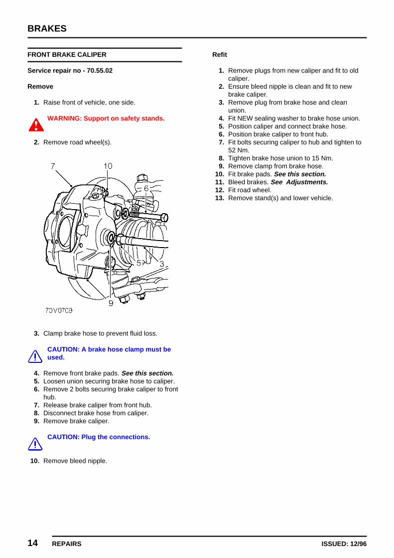
BRAKES
14 REPAIRS ISSUED: 12/96
FRONT BRAKE CALIPER
Service repair no - 70.55.02
Remove
1. Raise front of vehicle, one side.
WARNING: Support on safety stands.
2. Remove road wheel(s).
3. Clamp brake hose to prevent fluid loss.
CAUTION: A brake hose clamp must beused.
4. Remove front brake pads. See this section.5. Loosen union securing brake hose to caliper.6. Remove 2 bolts securing brake caliper to front
hub.7. Release brake caliper from front hub.8. Disconnect brake hose from caliper.9. Remove brake caliper.
CAUTION: Plug the connections.
10. Remove bleed nipple.
Refit
1. Remove plugs from new caliper and fit to oldcaliper.
2. Ensure bleed nipple is clean and fit to newbrake caliper.
3. Remove plug from brake hose and cleanunion.
4. Fit NEW sealing washer to brake hose union.5. Position caliper and connect brake hose.6. Position brake caliper to front hub.7. Fit bolts securing caliper to hub and tighten to
52 Nm.8. Tighten brake hose union to 15 Nm.9. Remove clamp from brake hose.
10. Fit brake pads. See this section.11. Bleed brakes. See Adjustments.12. Fit road wheel.13. Remove stand(s) and lower vehicle.

BRAKES
REPAIRS 15ISSUED: 12/96
REAR WHEEL BRAKE CYLINDER
Service repair no - 70.60.19
Remove
1. Remove rear brake shoes. See this section.2. Clamp rear brake hose to prevent fluid loss.
CAUTION: A brake hose clamp must beused.
3. Remove bleed nipple.4. Loosen union and disconnect brake pipe from
wheel cylinder.
CAUTION: Plug the connections.
5. Remove ’C’ clip securing wheel cylinder toback plate.
6. Remove wheel cylinder and discard gasket.
Refit
1. Clean mating faces of cylinder and backplate.2. Remove plugs from new cylinder and fit to old
cylinder.3. Using a new gasket position wheel cylinder to
back plate and secure with clip.4. Remove plug from brake pipe and clean brake
pipe union.5. Connect brake pipe to wheel cylinder and
tighten union to 14 Nm.6. Ensure bleed nipple is clean and hole is clear.7. Fit bleed nipple and tighten 9 Nm.8. Remove brake hose clamp.9. Fit rear brake shoes. See this section.
10. Bleed brakes. See Adjustments.
HANDBRAKE CABLE - FRONT
Service repair no - 70.35.14.
Remove
1. Remove drivers front seat. See BODY, Seatsand seat belts.
2. Remove Torx screw securing seat belt stalk tobody and remove stalk.
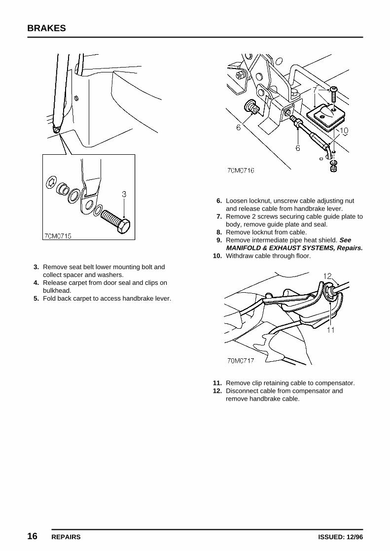
BRAKES
16 REPAIRS ISSUED: 12/96
3. Remove seat belt lower mounting bolt andcollect spacer and washers.
4. Release carpet from door seal and clips onbulkhead.
5. Fold back carpet to access handbrake lever.
6. Loosen locknut, unscrew cable adjusting nutand release cable from handbrake lever.
7. Remove 2 screws securing cable guide plate tobody, remove guide plate and seal.
8. Remove locknut from cable.9. Remove intermediate pipe heat shield. See
MANIFOLD & EXHAUST SYSTEMS, Repairs.10. Withdraw cable through floor.
11. Remove clip retaining cable to compensator.12. Disconnect cable from compensator and
remove handbrake cable.

BRAKES
REPAIRS 17ISSUED: 12/96
Refit
1. Connect cable to compensator and secure withclip.
2. Feed cable into vehicle.3. Fit intermediate pipe heat shield. See
MANIFOLD & EXHAUST SYSTEMS, Repairs.4. Fit locknut to cable.5. Position cable guide plate and seal, secure
with screws.6. Connect cable to handbrake lever and fit cable
adjusting nut.7. Adjust handbrake. See Adjustments.8. Position carpet and secure to door seal and
clips on bulkhead.9. Extend seat belt and align to lower mounting.
Fit lower mounting bolt, spacers and washersand tighten to 30 Nm.
10. Position seat belt stalk, spacer and washers, fitTorx bolt and tighten to 32 Nm.
11. Fit drivers front seat. See BODY, Seats andseat belts.


RESTRAINT SYSTEMS
CONTENTS Page
DESCRIPTION AND OPERATION
COMPONENT LOCATION 1.......................................................................................DESCRIPTION 2.........................................................................................................OPERATION 3.............................................................................................................
PRECAUTIONSPRECAUTIONS 1........................................................................................................WARNING LABELS 4..................................................................................................AIRBAG AND PRE-TENSIONER, MANUAL DEPLOYMENT 6...................................
REPAIRSDRIVERS AIR BAG MODULE 1..................................................................................FRONT SEAT BELT PRE-TENSIONER 2...................................................................SRS AND DIAGNOSTIC CONTROL UNIT 3...............................................................SUPPLEMENTARY RESTRAINT SYSTEM HARNESS 4...........................................

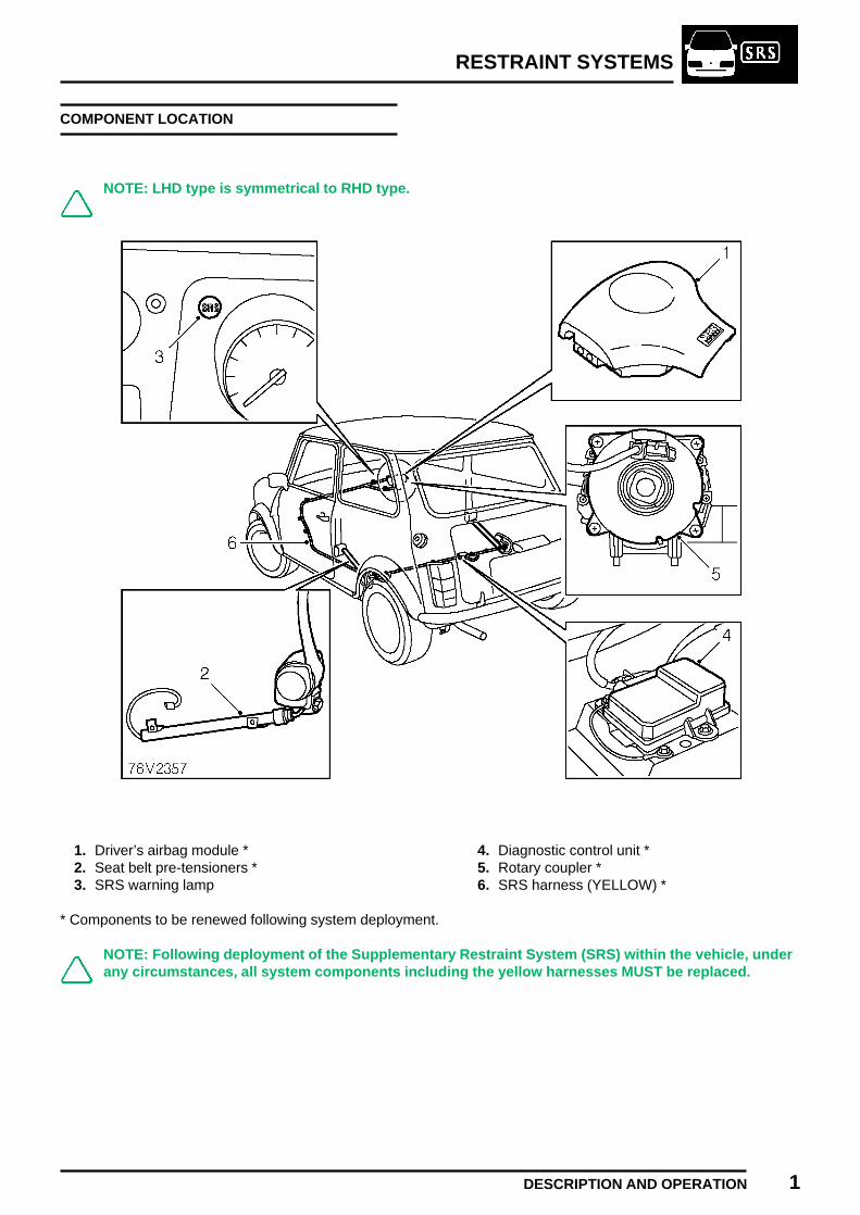
RESTRAINT SYSTEMS
DESCRIPTION AND OPERATION 1
COMPONENT LOCATION
NOTE: LHD type is symmetrical to RHD type.
1. Driver’s airbag module *2. Seat belt pre-tensioners *3. SRS warning lamp
4. Diagnostic control unit *5. Rotary coupler *6. SRS harness (YELLOW) *
* Components to be renewed following system deployment.
NOTE: Following deployment of the Supplementary Restraint System (SRS) within the vehicle, underany circumstances, all system components including the yellow harnesses MUST be replaced.

RESTRAINT SYSTEMS
2 DESCRIPTION AND OPERATION
DESCRIPTION
The airbag Supplementary Restraint System (SRS)is a safety device which, when deployed in the eventof a severe frontal impact, provides additionalprotection to the driver’s face and upper torso. Theairbag is designed to inflate when the vehicle isexceeding a set speed and receives a frontal impactwithin the area shaded.
The pre-tensioner consists of the seat belt buckleand stalk, a piston and a pyrotechnic device. Thepre-tensioners, fitted to both driver and passengerseat belt mechanisms are designed to remove anyplay in the the lap and diagonal belts in the event ofa severe frontal impact.
OPERATION
CAUTION: The diagnostic control unit is anon-serviceable component and noattempt should be made to repair or
modify the unit.
The diagnostic control unit (DCU) which is mountedwithin the passenger compartment performs twofunctions:
1. It continually monitors the airbag system forfaults;
2. It provides a fire signal to the airbag andpre-tensioners in the event of a crash.
The SRS warning lamp illuminates to inform thedriver of any airbag system faults and during asystem self test.
The diagnostic control unit comprises of thefollowing circuits which control the airbag system:
1. The crash sensor determines the severity ofany impact and can discriminate betweenrough road conditions and an actual crash.
2. The safing sensor is wired in series with thecrash sensor. The fire signal from the crashsensor therefore, passes through the safingsensor which confirms a crash is taking place.
3. The regulator circuit maintains stability of thesystem in the event of battery voltage drop.
4. The back-up power supply provides power tothe system in the event of the battery beingdamaged or disconnected during the impact.

RESTRAINT SYSTEMS
DESCRIPTION AND OPERATION 3REVISED: 12/96
Airbag
When triggered, the fire signal from the diagnosticcontrol unit passes via the airbag harness to theairbag module. Grains of Nitrocellulose andNitroglycerine inside the airbag module, ignite andcombine in a chemical reaction to form a largeamount of Nitrogen gas, leading to inflation of theairbag in approximately 30 milli-seconds.
As the driver moves forward into the airbag it rapidlydeflates to provide progressive deceleration andreduce the risk of injuries.
Seat belt pre-tensioners
The front seat belt reels are linked by cables to gasgenerators housed within remote steel tubes. Thegenerators are driven by small quantities ofnitrocellulose. On receiving a fire signal from theDCU, the generators deploy to force pistons downthe steel tubes, pulling the cables tight. The cablesare connected to the seat belt reels which in turn pullthe seat belts tight, reducing any slack in the belts.
Sequence of operation:
1. The main sensor and the safing sensor detectcrash conditions.
2. The DCU supplies an electrical pulse to theairbag igniter and pre-tensioners.
3. Airbag and pre-tensioners deploy.
It takes about 0.1 seconds from the beginning of theairbag deployment until it is completely deflated.
System check
The SRS warning lamp, located on the fascia,illuminates when the electrical circuits are switchedon whilst the system performs a self diagnosis test. Ifthe system finds no fault during self diagnosis thelight will extinguish after approximately 5 secondsand remain extinguished.
In the event of a fault in the system, the warning lightwill either:
1. Illuminate continuously;2. Illuminate for 0.5 second, extinguish, then
illuminate continuously;3. Fail to illuminate during the self diagnosis test.
Fault diagnosis
Diagnosis is accomplished using TestBookconnected to the vehicle diagnostic connector whichis located on a bracket by the foot pedals.


RESTRAINT SYSTEMS
PRECAUTIONS 1
PRECAUTIONS
Making the system safe
• Always disconnect the battery and wait 10minutes to allow the SRS back-up circuit to fullydischarge before commencing work on theairbag system.
• Always disconnect both battery leads, earth leadfirst before commencing work.
Care Points
ALWAYS:
• Carefully inspect any SRS part beforeinstallation.
• Use a digital circuit tester to check the system.
WARNING: Using an analogue circuittester may cause an accidentaldeployment and possible injury.
• Check SRS harness is correctly routed.• Check SRS connectors are mated correctly after
completion of work.
NEVER:
• Drop any component.
NOTE: The airbag diagnostic control unitis a shock sensitive device and must behandled with extreme care.
• Wrap arms around an airbag module.• Attach anything to the airbag cover.• Attempt to repair any component.• Apply electrical power to a component except as
part of an approved test procedure.• Transport airbag modules in the passenger
compartment of a car.• Install any SRS component that shows signs of
being dropped or improperly handled, such asdents, cracks or deformation.
• Install used SRS parts from another car. Whenrepairing an SRS, use only genuine new parts.

RESTRAINT SYSTEMS
2 PRECAUTIONS
Handling and Storage
• Do not try to disassemble the airbag assembly orpretensioner. They have no serviceable parts.Once an airbag or pre-tensioner has beendeployed, it cannot be repaired or reused.
• Do not carry a seat belt pre-tensioner assemblyby the electrical lead, or allow the reel or tube tohang on the flexible link.
• Be careful that the airbag assembly receives nostrong shocks; it could deploy.
• Special bolts are necessary for installing theairbag assembly. Do not use other bolts.
Airbag storage
For temporary storage of the airbag assembly duringservice, observe the following precautions:
• Always keep components dry.• Always carry the airbag module with the pad
surface face up.• Store the removed airbag assembly with the pad
surface face up.• Do not allow anything to rest on the airbag
module.• Place the airbag module in a designated storage
area.
WARNING: If the airbag is improperlystored face down, accidental deploymentcould propel the unit with enough force to
cause serious injury.
• Store the removed airbag assembly on a secureflat surface away from any electrical equipmentor high heat source (exceeding 85°C/185°F) andfree of any oil, grease, detergent or water.
CAUTION: Improper handling or storagecan internally damage the airbagassembly, making it inoperative. If you
suspect the airbag assembly has been damaged,install a new unit and refer to theDeployment/Disposal Procedures for disposingof the damaged airbag.
Overnight storage
Airbag modules are classed as explosive articlesand as such must be stored in an approved securesteel cabinet which has been registered by the localauthority.
Seat belt pre-tensioner storage
For temporary storage of the seat belt pre-tensionerduring service, observe the following precautions:• Place the pre-tensioner in designated storage
area.• Store the removed pre-tensioner on a secure, flat
surface away from heat, oil, grease, detergent orwater.
CAUTION: Improper handling or storagecan damage the pre-tensioner assembly. Ifdamage is suspected, install a new
assembly.
Overnight storage
The seat belt pre-tensioners are classed asexplosive articles and as such must be stored in anapproved secure steel cabinet which has beenregistered by the local authority.

RESTRAINT SYSTEMS
PRECAUTIONS 3
Wiring and connectors
• Never attempt to modify, splice or repair SRSwiring. Never install electronic equipment suchas; a mobile telephone, two way radio or in-carentertainment system in such a way that itinterferes electrically with the airbag harness.
NOTE: SRS wiring can be identified byspecial yellow outer protective covering.
• Always ensure SRS harnesses are routedcorrectly. Be careful to avoid trapping or pinchingthe SRS harness. Look out for possible points ofchafing.
• Always use specified earth fixings tightened tothe correct torque. Poor earthing can causeintermittent problems that are difficult todiagnose.
• Ensure all airbag harness connectors are matedcorrectly and securely fastened. Do not leave theconnectors hanging loose.

RESTRAINT SYSTEMS
4 PRECAUTIONS
WARNING LABELS
A combination of symbols/icons is displayed (eitherin a suitable, prominent position or is attached to thecomponent itself) to indicate:
(a) The need for caution when working in closeproximity to SRS components.
(b) The publication where suitable reference andadvice can be found (usually Workshop Manual orOwner’s Handbook).
NOTE: It is imperative that before anywork is undertaken on the SRS system,the appropriate publication is read
thoroughly.
The following list indicates current locations forwarning labels. Exact positions may vary dependenton legislation and market trends.
1. Front windscreen
Refer to the Owner’s Handbook for informationon the airbag system.
2. Rotary coupler
A - Refer to the Workshop Manual for detailedinstructions.B - Ensure wheels are in the straight aheadposition before removal and refitting.C - ROVER Part Number/Bar code - The codemust be recorded and quoted for orderingpurposes.
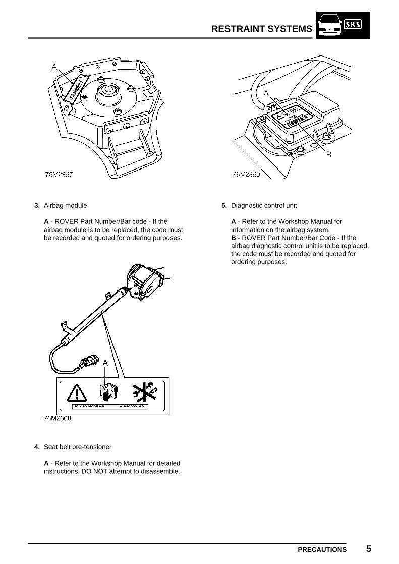
RESTRAINT SYSTEMS
PRECAUTIONS 5
3. Airbag module
A - ROVER Part Number/Bar code - If theairbag module is to be replaced, the code mustbe recorded and quoted for ordering purposes.
4. Seat belt pre-tensioner
A - Refer to the Workshop Manual for detailedinstructions. DO NOT attempt to disassemble.
5. Diagnostic control unit.
A - Refer to the Workshop Manual forinformation on the airbag system.B - ROVER Part Number/Bar Code - If theairbag diagnostic control unit is to be replaced,the code must be recorded and quoted forordering purposes.

RESTRAINT SYSTEMS
6 PRECAUTIONS
AIRBAG AND PRE-TENSIONER, MANUALDEPLOYMENT
If a vehicle is to be scrapped and contains anundeployed airbag module, or pre-tensioner, thecomponents must be manually deployed. Thisoperation should only be carried out using thefollowing recommended manual deploymentprocedure.
Before deployment is started the deployment toolself test procedure should be carried out.
Deployment tool SMD 4082/1 self test procedure
1. Insert blue and yellow connectors of tool leadinto corresponding sockets on face of tool.
2. Connect crocodile clips of second tool lead tobattery, red to positive and black to negative.
3. Red "READY" light should illuminate.4. Press and hold both operating buttons.5. Green "DEFECTIVE" light should illuminate.6. Release both operating buttons.7. Red "READY" light should illuminate.8. Disconnect tool from battery.9. Disconnect blue and yellow connectors from
tool face sockets.10. Self test now complete.
Deployment of pre-tensioner fitted to vehicle
These guidelines are written to aid authorisedpersonnel to carry out the safe disposal of thepre-tensioner.
WARNING:
• Only use the Rover approved deploymentequipment.
• Deploy pre-tensioner in a designated area.• Ensure pre-tensioner is not damaged or
ruptured before deploying.• Notify relevant authorities.
1. Carry out deployment tool self test.2. Remove 3 screws securing rear cubby hole
cover to body and remove cover.3. Disconnect pre-tensioner harness connector.
WARNING: Ensure deployment tool SMD4082/1 is not connected to battery.

RESTRAINT SYSTEMS
PRECAUTIONS 7
4. Connect flylead SMD 4082/5 to pre-tensionerconnector.
5. Connect flylead SMD 4082/5 to tool SMD4082/1.
6. Connect tool SMD 4082/1 to battery.
WARNING: Ensure all personnel arestanding at least 15 metres away fromvehicle.
7. Press both operating buttons to deploypre-tensioner.
8. DO NOT return to the vehicle for 5 minutes.9. Using gloves, remove pre-tensioner from body,
place pre-tensioner in plastic bag, and sealbag.
10. Transport deployed pre-tensioner todesignated area for incineration.
NOTE: DO NOT transport pre-tensioner inthe vehicle passenger compartment.
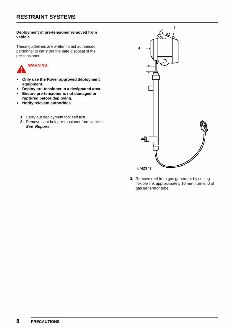
RESTRAINT SYSTEMS
8 PRECAUTIONS
Deployment of pre-tensioner removed fromvehicle
These guidelines are written to aid authorisedpersonnel to carry out the safe disposal of thepre-tensioner.
WARNING:
• Only use the Rover approved deploymentequipment.
• Deploy pre-tensioner in a designated area.• Ensure pre-tensioner is not damaged or
ruptured before deploying.• Notify relevant authorities.
1. Carry out deployment tool self test.2. Remove seat belt pre-tensioner from vehicle.
See Repairs.
3. Remove reel from gas generator by cuttingflexible link approximately 10 mm from end ofgas generator tube.
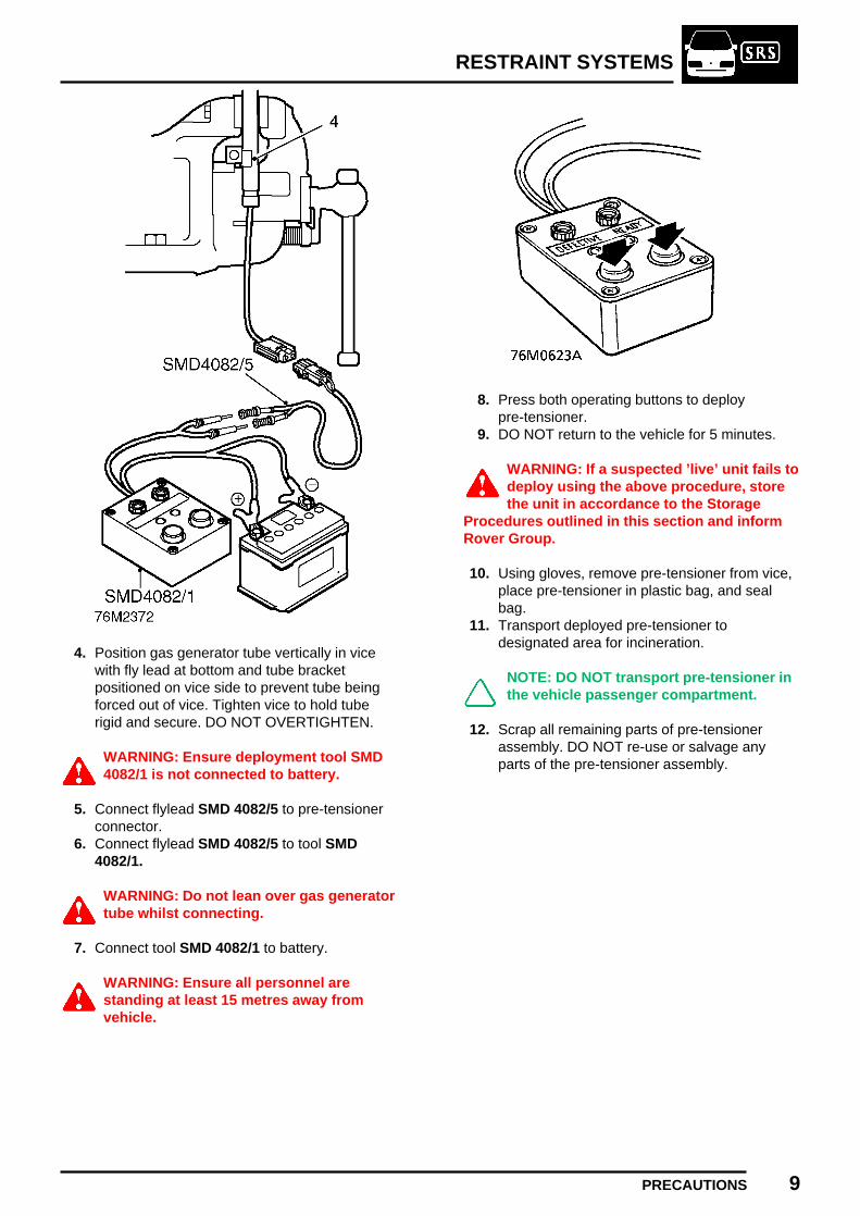
RESTRAINT SYSTEMS
PRECAUTIONS 9
4. Position gas generator tube vertically in vicewith fly lead at bottom and tube bracketpositioned on vice side to prevent tube beingforced out of vice. Tighten vice to hold tuberigid and secure. DO NOT OVERTIGHTEN.
WARNING: Ensure deployment tool SMD4082/1 is not connected to battery.
5. Connect flylead SMD 4082/5 to pre-tensionerconnector.
6. Connect flylead SMD 4082/5 to tool SMD4082/1.
WARNING: Do not lean over gas generatortube whilst connecting.
7. Connect tool SMD 4082/1 to battery.
WARNING: Ensure all personnel arestanding at least 15 metres away fromvehicle.
8. Press both operating buttons to deploypre-tensioner.
9. DO NOT return to the vehicle for 5 minutes.
WARNING: If a suspected ’live’ unit fails todeploy using the above procedure, storethe unit in accordance to the Storage
Procedures outlined in this section and informRover Group.
10. Using gloves, remove pre-tensioner from vice,place pre-tensioner in plastic bag, and sealbag.
11. Transport deployed pre-tensioner todesignated area for incineration.
NOTE: DO NOT transport pre-tensioner inthe vehicle passenger compartment.
12. Scrap all remaining parts of pre-tensionerassembly. DO NOT re-use or salvage anyparts of the pre-tensioner assembly.

RESTRAINT SYSTEMS
10 PRECAUTIONS
Deployment of airbag module
These guidelines are written to aid authorisedpersonnel to carry out the safe disposal of airbagmodules when removed from the vehicle.
WARNING:
• Only use the Rover approved deploymentequipment.
• Deploy airbag modules in a well ventilateddesignated area.
• Ensure airbag module is not damaged orruptured before deploying.
• Notify relevant authorities.
1. Carry out deployment tool self test.2. Remove airbag module from steering wheel.
See Repairs.
3. Position tool SMD 4082/2 in vice, ensuring thatvice jaws grip tool above bottom flange toprevent possibility of tool being forced upwardsfrom vice. Tighten vice.
4. Secure airbag module to tool SMD 4082/2.Ensure module is correctly secured using bothfixings.
5. Ensure airbag module mounting brackets aresecure.
WARNING: Ensure deployment tool SMD4082/1 is not connected to battery.
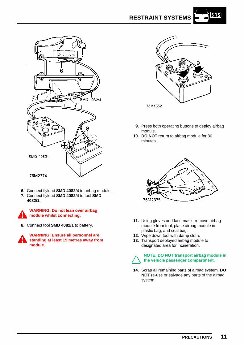
RESTRAINT SYSTEMS
PRECAUTIONS 11
6. Connect flylead SMD 4082/4 to airbag module.7. Connect flylead SMD 4082/4 to tool SMD
4082/1.
WARNING: Do not lean over airbagmodule whilst connecting.
8. Connect tool SMD 4082/1 to battery.
WARNING: Ensure all personnel arestanding at least 15 metres away frommodule.
9. Press both operating buttons to deploy airbagmodule.
10. DO NOT return to airbag module for 30minutes.
11. Using gloves and face mask, remove airbagmodule from tool, place airbag module inplastic bag, and seal bag.
12. Wipe down tool with damp cloth.13. Transport deployed airbag module to
designated area for incineration.
NOTE: DO NOT transport airbag module inthe vehicle passenger compartment.
14. Scrap all remaining parts of airbag system. DONOT re-use or salvage any parts of the airbagsystem.

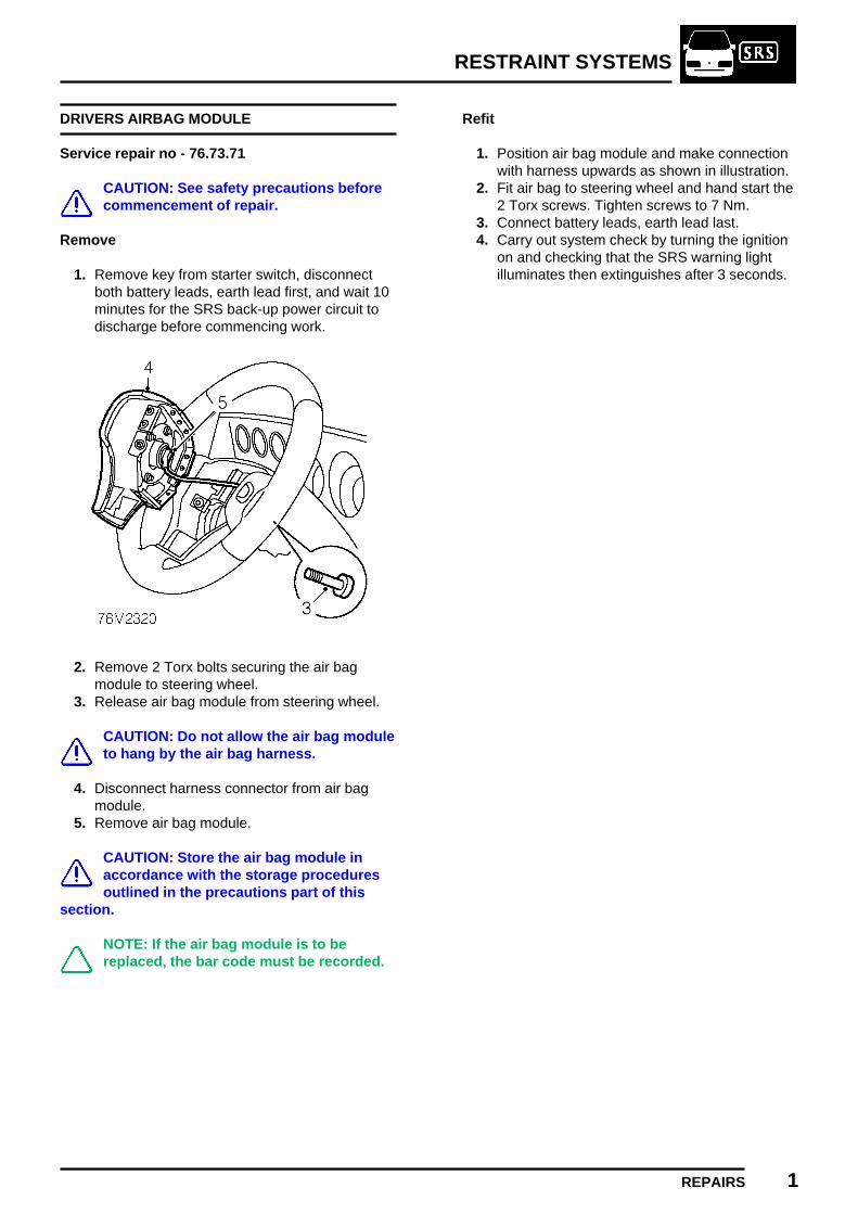
RESTRAINT SYSTEMS
REPAIRS 1
DRIVERS AIRBAG MODULE
Service repair no - 76.73.71
CAUTION: See safety precautions beforecommencement of repair.
Remove
1. Remove key from starter switch, disconnectboth battery leads, earth lead first, and wait 10minutes for the SRS back-up power circuit todischarge before commencing work.
2. Remove 2 Torx bolts securing the air bagmodule to steering wheel.
3. Release air bag module from steering wheel.
CAUTION: Do not allow the air bag moduleto hang by the air bag harness.
4. Disconnect harness connector from air bagmodule.
5. Remove air bag module.
CAUTION: Store the air bag module inaccordance with the storage proceduresoutlined in the precautions part of this
section.
NOTE: If the air bag module is to bereplaced, the bar code must be recorded.
Refit
1. Position air bag module and make connectionwith harness upwards as shown in illustration.
2. Fit air bag to steering wheel and hand start the2 Torx screws. Tighten screws to 7 Nm.
3. Connect battery leads, earth lead last.4. Carry out system check by turning the ignition
on and checking that the SRS warning lightilluminates then extinguishes after 3 seconds.
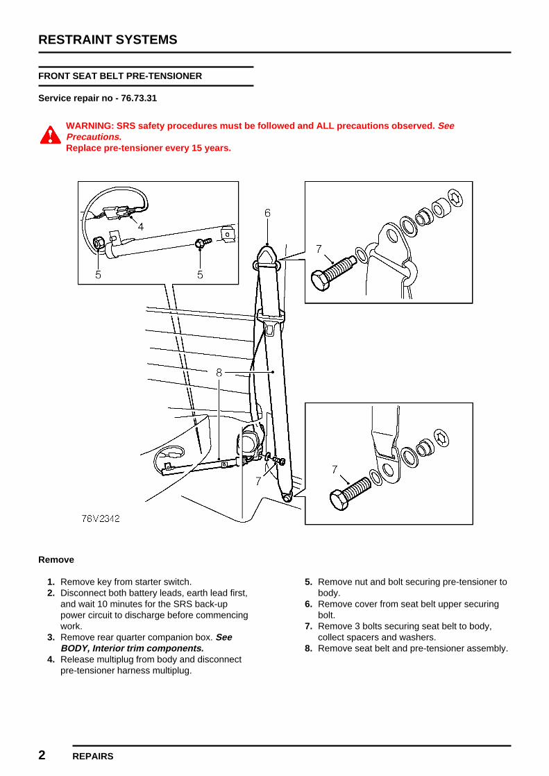
RESTRAINT SYSTEMS
2 REPAIRS
FRONT SEAT BELT PRE-TENSIONER
Service repair no - 76.73.31
WARNING: SRS safety procedures must be followed and ALL precautions observed. SeePrecautions.Replace pre-tensioner every 15 years.
Remove
1. Remove key from starter switch.2. Disconnect both battery leads, earth lead first,
and wait 10 minutes for the SRS back-uppower circuit to discharge before commencingwork.
3. Remove rear quarter companion box. SeeBODY, Interior trim components.
4. Release multiplug from body and disconnectpre-tensioner harness multiplug.
5. Remove nut and bolt securing pre-tensioner tobody.
6. Remove cover from seat belt upper securingbolt.
7. Remove 3 bolts securing seat belt to body,collect spacers and washers.
8. Remove seat belt and pre-tensioner assembly.

RESTRAINT SYSTEMS
REPAIRS 3REVISED: 12/96
9. Remove Torx screw securing seat belt stalkand remove stalk.
Refit
1. Position seat belt stalk, spacer and washers, fitTorx bolt and tighten to 32 Nm.
2. Position seat belt and pre-tensioner assemblyto body, fit and tighten bolt to 30 Nm.
3. Extend seat belt and align to upper mounting.Fit upper mounting bolt, spacer and washersand tighten to 32 Nm.
4. Fit cover to upper seat belt securing bolt.5. Extend seat belt and align to lower mounting.
Fit lower mounting bolt, spacer and washersand tighten to 30 Nm.
6. Fit nut and screw securing pre-tensioner tobody. Tighten nut to 6 Nm and screw to 1.5Nm.
7. Connect multiplug to pre-tensioner harnessand secure to bracket on body.
8. Fit rear quarter companion box. See BODY,Interior trim components.
9. Connect both battery leads, earth lead last.10. Carry out system check by turning ignition on
and check that the SRS warning lightilluminates then extinguishes after 3 seconds.
SRS AND DIAGNOSTIC CONTROL UNIT
Service repair no - 76.73.72
Remove
CAUTION: See safety precautions beforecommencement of repair.
1. Remove key from starter switch, disconnectboth battery leads, earth lead first, and wait 10minutes for the SRS back-up power circuit todischarge before starting work.
2. Slide drivers seat forward and fold downsquab.
3. Release carpet from under rear seat for accessto SRS control unit.
4. Disconnect multiplug from control unit.5. Remove and discard 3 Torx screws securing
control unit to floor.6. Remove control unit.
Refit
CAUTION: Ensure unit and bracket facesare clean and free from burrs. Anincorrectly mounted unit could cause the
system to malfunction.
1. Position control unit, fit NEW Torx screws andtighten to 9 Nm.
2. Connect harness multiplug to control unit.3. Position floor carpet.4. Reposition drivers seat.5. Connect battery leads, earth lead last.6. Carry out system check by turning the ignition
on and checking that the SRS warning lightilluminates the extinguishes after 3 seconds.

RESTRAINT SYSTEMS
4 REPAIRS
SUPPLEMENTARY RESTRAINT SYSTEMHARNESS
Service repair no - 76.73.73
CAUTION:
• Do not install used SRS parts from another car. When repairing an SRS, use only genuine new ROVER parts.• Never attempt to modify, splice, or repair SRS wiring.
NOTE: SRS wiring can be identified by its yellow or black with yellow stripe outer protective covering.
RESTRAINT SYSTEMS
REPAIRS 5REVISED: 12/96
Remove
1. Remove key from starter switch, disconnectboth battery leads, earth lead first, and wait 10minutes for the SRS back-up circuit todischarge before commencing work.
2. Remove fascia. See BODY, Interior trimcomponents.
3. Remove carpet. See BODY, Interior trimcomponents.
4. Remove steering column nacelle. SeeSTEERING, Repairs.
5. Remove quarter panel companion boxes. SeeBODY, Interior trim components.
6. Release and disconnect multiplugs from seatbelt pre-tensioners.
7. Release pre-tensioner leads from companionbox panels.
8. Disconnect multiplug from SRS control unit.9. Raise rear seat cushion and release 6 harness
clips.10. Remove bolt securing SRS harness earth lead
to body.11. Release 2 clips securing SRS harness to
bulkhead.12. Release and disconnect multiplug from fuse
box feed.13. Disconnect multiplug from rotary coupler.14. Remove 2 cable ties securing SRS harness to
steering column.15. Remove 2 clips securing SRS harness to body.16. Remove 5 cable ties securing SRS harness to
bulkhead and remove SRS harness.17. Remove clips from harness.
Refit
1. Fit NEW clips to harness.2. Fit harness to vehicle.
CAUTION: Always ensure SRS harness isrouted correctly. Avoid trapping orpinching the SRS harness. Look out for
possible points of chafing.
3. Route the harness to position and secure withcable ties.
4. Connect harness to rotary coupler and secureto steering column with cable ties.
5. Connect harness multiplug to fuse box.6. Secure SRS harness clips to bulkhead.7. Secure SRS harness clips to rear seat pan.8. Connect harness multiplug to SRS control unit.9. Fit bolt securing harness earth lead to body
and tighten to 10 Nm.10. Fit harness leads through companion box
panels, secure grommets and connect seatbelt pre-tensioner multiplugs.
11. Position rear seat cushion.
CAUTION: Ensure all SRS harnessconnectors are mated correctly andsecurely fastened. Do not leave the
connectors hanging loose.
12. Fit rear quarter companion boxes. See BODY,Interior trim components.
13. Fit steering column nacelle. See STEERING,Repairs.
14. Fit carpet. See BODY, Interior trimcomponents.
15. Fit fascia. See BODY, Interior trimcomponents.
16. Connect battery leads, earth lead last.17. Carry out system check by turning the ignition
on and checking that the SRS warning lightilluminates then extinguishes after 3 seconds.


BODY
CONTENTS Page
EXTERIOR FITTINGS
BONNET 1...................................................................................................................BONNET ALIGNMENT 2.............................................................................................BONNET RELEASE CABLE 3.....................................................................................DOOR STRIKER - ADJUST 4.....................................................................................FRONT GRILLE 5........................................................................................................FRONT BUMPER 5.....................................................................................................REAR BUMPER 6........................................................................................................FRONT WHEEL ARCH EXTENSION 6.......................................................................REAR WHEEL ARCH EXTENSION 7.........................................................................
INTERIOR TRIM COMPONENTSREAR QUARTER WOODEN FINISHER 1..................................................................REAR QUARTER TRIM PAD 1...................................................................................REAR QUARTER COMPANION BOX 2......................................................................DOOR WOODEN FINISHER 2....................................................................................DOOR TRIM CASING 3...............................................................................................FASCIA TOP RAIL 4....................................................................................................FASCIA PANEL 5........................................................................................................CARPET 6...................................................................................................................GLOVE BOX 7.............................................................................................................
SCREENSWINDSCREEN 1.........................................................................................................
SEATS AND SEAT BELTSFRONT SEAT BELT 1.................................................................................................FRONT SEAT 1...........................................................................................................REAR SEAT BELT 2....................................................................................................REAR SEAT SQUAB 3................................................................................................REAR SEAT CUSHION 3............................................................................................


BODY
EXTERIOR FITTINGS 1REVISED: 12/96
BONNET
Service repair no - 76.16.01.99
Remove
1. Support the bonnet in the fully open position.2. Fit protective covers to wings.
3. Mark outlines of hinges on bonnet.4. Remove nuts and washers securing hinges to
bonnet.5. Release bonnet stay from body and secure to
bonnet.6. Remove bonnet.
Refit
1. Using assistance, position bonnet on hinges.2. Fit nuts and washers securing bonnet to
hinges.3. Align bonnet to hinge outlines.4. Tighten nuts securing hinges to body to 10 Nm.5. Remove protective covers.6. Lower and close bonnet.7. Adjust bonnet alignment. See this section.

BODY
2 EXTERIOR FITTINGS
BONNET ALIGNMENT
Service repair no - 76.16.02
Adjust
1. Check alignment of bonnet against both wings.
2. Open bonnet and mark outline of hinges.3. Loosen 4 nuts and adjust position of bonnet.4. Lightly tighten nuts securing hinges to body.5. Close bonnet and check alignment against
both wings.6. Open bonnet and re-adjust bonnet position if
necessary.7. Tighten nuts securing hinges to body to 10 Nm.8. Close bonnet and check alignment against
both wings.9. Open bonnet and repaint bare areas on
hinges.

BODY
EXTERIOR FITTINGS 3REVISED: 12/96
BONNET RELEASE CABLE
Service repair no - 76.16.29
Remove
1. Loosen lock nut securing bonnet releasehandle to mounting bracket.
2. Release handle from mounting bracket.
3. Release clip securing cable to body.
4. Disconnect bonnet lock return spring frombody.
5. Remove 2 bolts securing bonnet catch tobonnet locking platform.
6. Release bonnet catch to gain access to bonnetrelease cable.
7. Disconnect cable from bonnet catch.
8. Withdraw bonnet release cable throughbulkhead into passenger compartment.
9. Remove bonnet release cable

BODY
4 EXTERIOR FITTINGS REVISED: 12/96
Refit
1. Feed bonnet release cable through grommet inbulkhead into engine compartment.
2. Secure cable to clip on body.3. Connect cable to bonnet release catch.4. Position bonnet release catch to bonnet locking
platform, fit bolts but do not tighten.5. Connect bonnet lock return spring to body.6. Locate bonnet release handle on mounting
bracket and tighten nut.7. Lower bonnet and adjust position of bonnet
catch to meet the bonnet lock pin.8. Open bonnet and tighten bolts securing bonnet
catch to bonnet locking platform to 9 Nm.
DOOR STRIKER - ADJUST
Service repair no - 76.28.05
Adjust
1. Loosen 2 screws securing striker to body andclose door.
2. Check door for flush fit to adjacent panels andedges for equal gap.
3. Open door and tighten striker screws to 18 Nm.

BODY
EXTERIOR FITTINGS 5ISSUED: 12/96
FRONT GRILLE
Service repair no - 76.55.03
Remove
1. If fitted, lower the driving lamps for access togrille.
2. Remove 8 screws securing front grilleassembly to body.
3. Remove grille.
Do not carry out further dismantling ifcomponent is removed for access only.
4. Remove 2 screws securing side finishers togrille.
5. Remove side finishers.
Refit
1. Fit side finishers to grille and secure withscrews.
2. Fit grille and secure with screws.3. Reposition driving lamps if fitted.
FRONT BUMPER
Service repair no - 76.22.08
Remove
1. Remove 3 nuts securing front bumper to bodyand collect washers.
2. Remove front bumper.
Refit
1. Fit front bumper to body.2. Fit nuts and washers securing bumper to body
and tighten nuts.
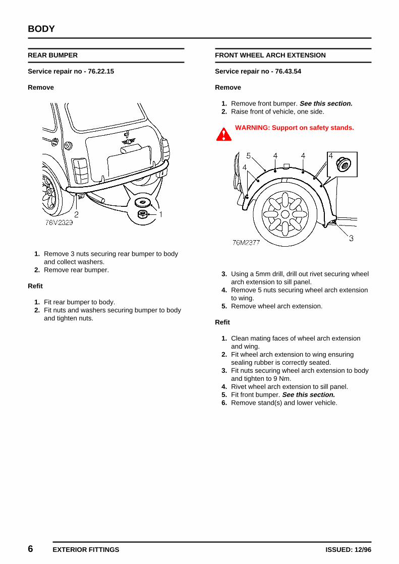
BODY
6 EXTERIOR FITTINGS ISSUED: 12/96
REAR BUMPER
Service repair no - 76.22.15
Remove
1. Remove 3 nuts securing rear bumper to bodyand collect washers.
2. Remove rear bumper.
Refit
1. Fit rear bumper to body.2. Fit nuts and washers securing bumper to body
and tighten nuts.
FRONT WHEEL ARCH EXTENSION
Service repair no - 76.43.54
Remove
1. Remove front bumper. See this section.2. Raise front of vehicle, one side.
WARNING: Support on safety stands.
3. Using a 5mm drill, drill out rivet securing wheelarch extension to sill panel.
4. Remove 5 nuts securing wheel arch extensionto wing.
5. Remove wheel arch extension.
Refit
1. Clean mating faces of wheel arch extensionand wing.
2. Fit wheel arch extension to wing ensuringsealing rubber is correctly seated.
3. Fit nuts securing wheel arch extension to bodyand tighten to 9 Nm.
4. Rivet wheel arch extension to sill panel.5. Fit front bumper. See this section.6. Remove stand(s) and lower vehicle.
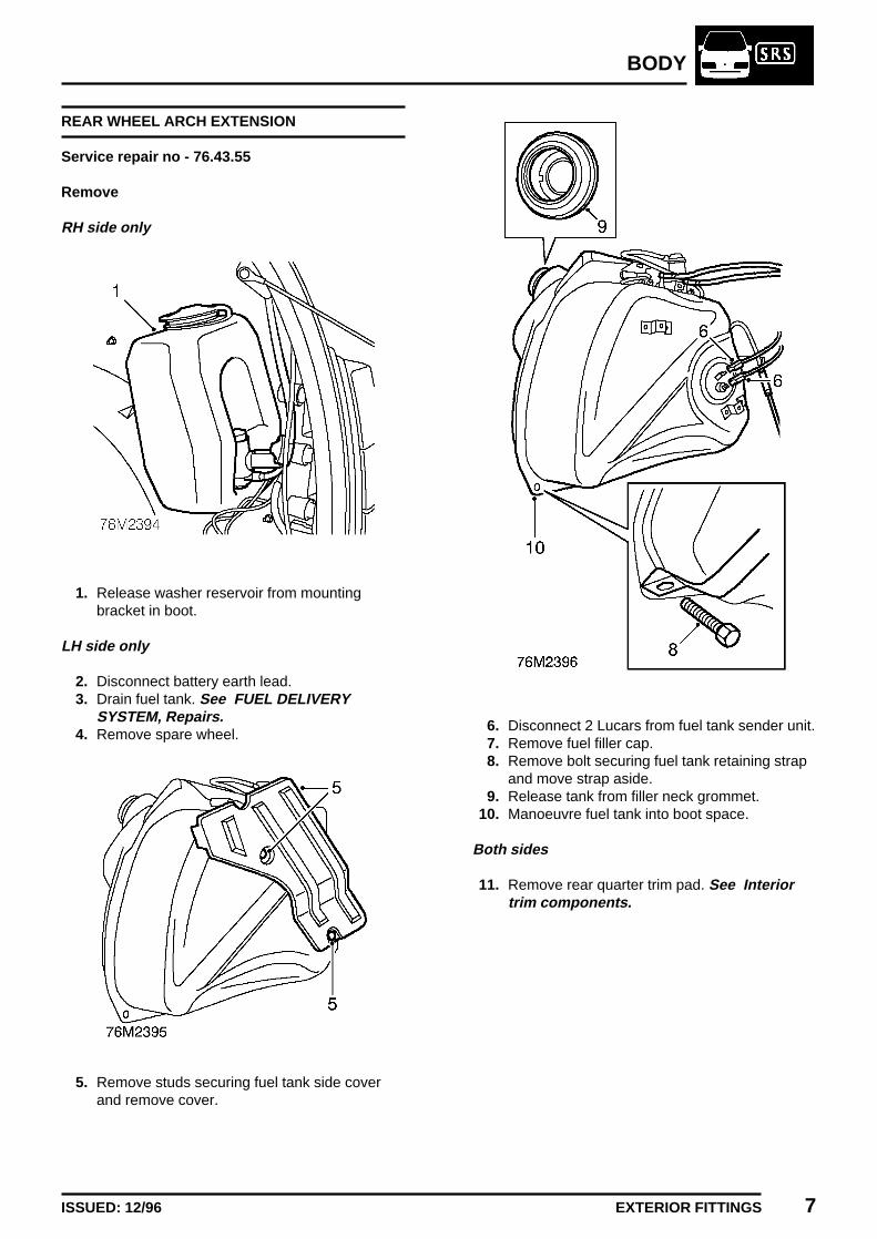
BODY
EXTERIOR FITTINGS 7ISSUED: 12/96
REAR WHEEL ARCH EXTENSION
Service repair no - 76.43.55
Remove
RH side only
1. Release washer reservoir from mountingbracket in boot.
LH side only
2. Disconnect battery earth lead.3. Drain fuel tank. See FUEL DELIVERY
SYSTEM, Repairs.4. Remove spare wheel.
5. Remove studs securing fuel tank side coverand remove cover.
6. Disconnect 2 Lucars from fuel tank sender unit.7. Remove fuel filler cap.8. Remove bolt securing fuel tank retaining strap
and move strap aside.9. Release tank from filler neck grommet.
10. Manoeuvre fuel tank into boot space.
Both sides
11. Remove rear quarter trim pad. See Interiortrim components.

BODY
8 EXTERIOR FITTINGS ISSUED: 12/96
12. Using a 5mm drill, drill out rivet securing wheelarch extension to sill panel.
13. Remove 5 nuts securing wheel arch extensionto body.
14. Remove wheel arch extension.
Refit
1. Clean mating faces of wheel arch extensionand body.
2. Fit wheel arch extension to body ensuringsealing rubber is correctly seated.
3. Fit nuts securing wheel arch extension to bodyand tighten to 9 Nm.
4. Rivet wheel arch extension to sill panel.5. Fit rear quarter trim pad. See Interior trim
components.
LH side only
6. Manoeuvre fuel tank into position and positionrestraining strap.
7. Fit and tighten strap retaining bolt.8. Connect Lucars to sender unit.9. Fit fuel tank side cover and secure with studs.
10. Fit spare wheel.11. Refill fuel tank with fuel.12. Connect battery earth lead.
RH side only
13. Secure washer reservoir to mounting bracket.

BODY
INTERIOR TRIM COMPONENTS 1REVISED: 12/96
REAR QUARTER WOODEN FINISHER
Service repair no - 76.13.71
Remove
1. Remove 2 screws securing rear quarterwooden finisher to body.
2. Remove rear quarter finisher.
Refit
1. Position rear quarter finisher and secure withscrews.
REAR QUARTER TRIM PAD
Service repair no - 76.13.12
Remove
1. Remove rear quarter companion box. See thissection.
2. Remove rear quarter wooden finisher. See thissection.
3. Release rear quarter trim pad from body.4. Remove rear quarter trim pad.
Refit
1. Fit rear quarter trim pad.2. Fit rear quarter wooden finisher. See this
section.3. Fit rear quarter companion box. See this
section.

BODY
2 INTERIOR TRIM COMPONENTS REVISED: 12/96
REAR QUARTER COMPANION BOX
Service repair no - 76.13.51
Remove
1. Release 2 seat belt guides from companionbox.
2. Remove 2 rivets securing companion box tobody.
3. Raise companion box and release seat beltsthrough slots.
4. Remove companion box.
Refit
1. Position rear quarter companion box andlocate seat belts.
2. Position companion box and secure with rivets.3. Secure seat belt guides to companion box.
DOOR WOODEN FINISHER
Service repair no - 76.34.15
Remove
1. Remove 3 screws securing wooden finisher tofront door.
2. Remove door finisher.
Refit
1. Position finisher to front door and secure withscrews.
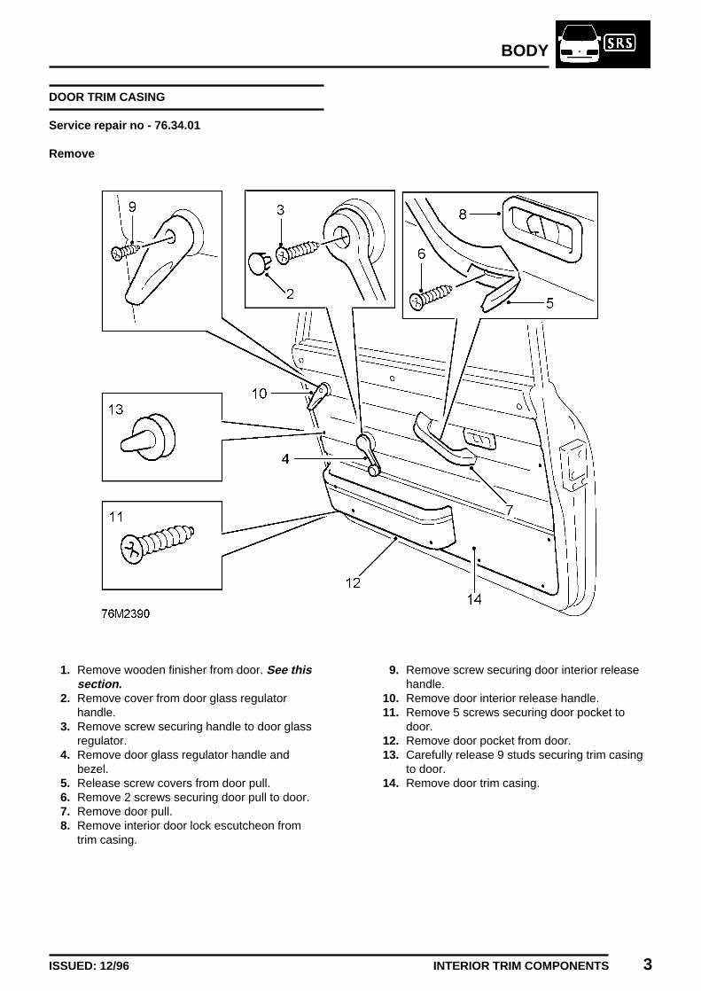
BODY
INTERIOR TRIM COMPONENTS 3ISSUED: 12/96
DOOR TRIM CASING
Service repair no - 76.34.01
Remove
1. Remove wooden finisher from door. See thissection.
2. Remove cover from door glass regulatorhandle.
3. Remove screw securing handle to door glassregulator.
4. Remove door glass regulator handle andbezel.
5. Release screw covers from door pull.6. Remove 2 screws securing door pull to door.7. Remove door pull.8. Remove interior door lock escutcheon from
trim casing.
9. Remove screw securing door interior releasehandle.
10. Remove door interior release handle.11. Remove 5 screws securing door pocket to
door.12. Remove door pocket from door.13. Carefully release 9 studs securing trim casing
to door.14. Remove door trim casing.

BODY
4 INTERIOR TRIM COMPONENTS ISSUED: 12/96
Refit
1. Fit new studs as necessary to trim casing andensure all studs are slotted fully into position.
2. Position trim casing to door, align studs andpress to engage on door.
3. Position door pocket to door and secure withscrews.
4. Fit door interior release handle and secure withscrew.
5. Fit interior door lock escutcheon an secure totrim casing.
6. Position door pull and secure with screws.7. Fit screw covers to door pull.8. Fit handle and bezel to door glass regulator
and tighten screw.9. Fit screw cover to door glass regulator handle.
10. Fit wooden finisher to door. See this section.
FASCIA TOP RAIL
Service repair no - 76.46.04
Remove
1. Remove windscreen. See Screens.2. Remove fascia panel. See this section.
3. Remove 3 nuts securing fascia rail to body andrelease rail.
4. Remove fascia rail.5. Remove demister ducts from fascia rail.
Refit
1. Fit demister ducts to fascia rail.2. Position fascia rail to body, fit nuts and tighten
to 9 Nm.3. Fit fascia panel. See this section.4. Fit windscreen. See Screens.
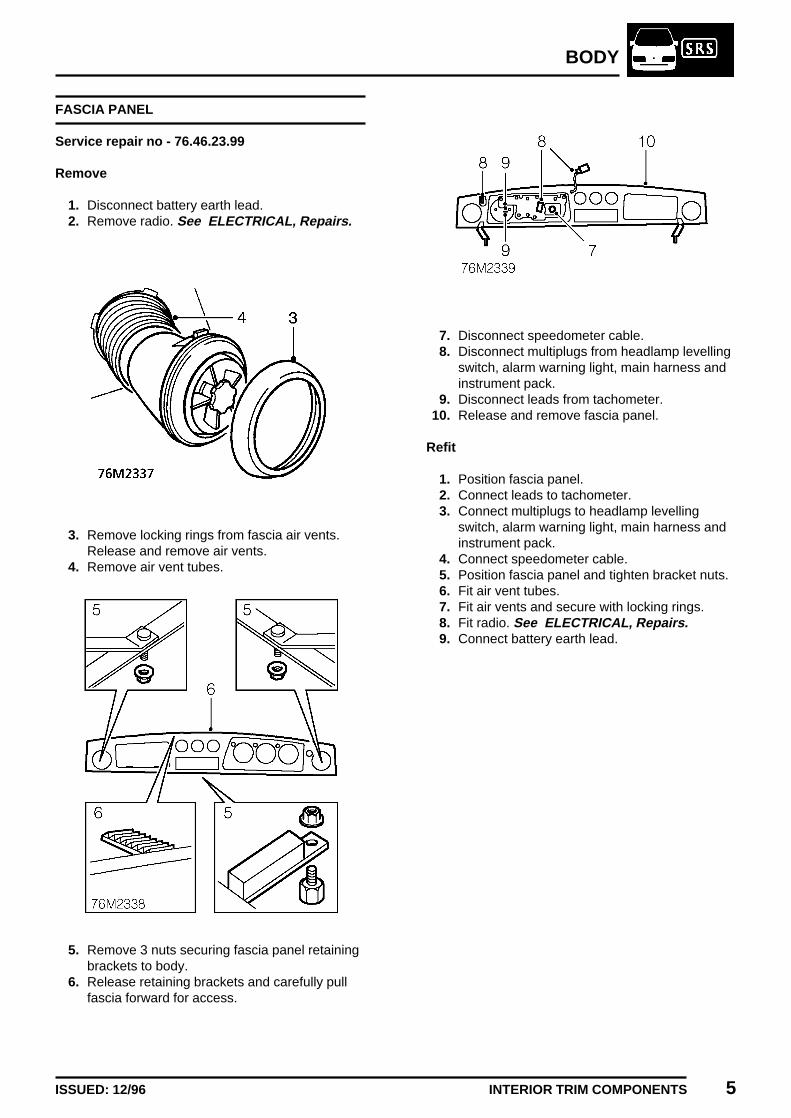
BODY
INTERIOR TRIM COMPONENTS 5ISSUED: 12/96
FASCIA PANEL
Service repair no - 76.46.23.99
Remove
1. Disconnect battery earth lead.2. Remove radio. See ELECTRICAL, Repairs.
3. Remove locking rings from fascia air vents.Release and remove air vents.
4. Remove air vent tubes.
5. Remove 3 nuts securing fascia panel retainingbrackets to body.
6. Release retaining brackets and carefully pullfascia forward for access.
7. Disconnect speedometer cable.8. Disconnect multiplugs from headlamp levelling
switch, alarm warning light, main harness andinstrument pack.
9. Disconnect leads from tachometer.10. Release and remove fascia panel.
Refit
1. Position fascia panel.2. Connect leads to tachometer.3. Connect multiplugs to headlamp levelling
switch, alarm warning light, main harness andinstrument pack.
4. Connect speedometer cable.5. Position fascia panel and tighten bracket nuts.6. Fit air vent tubes.7. Fit air vents and secure with locking rings.8. Fit radio. See ELECTRICAL, Repairs.9. Connect battery earth lead.

BODY
6 INTERIOR TRIM COMPONENTS ISSUED: 12/96
CARPET
Service repair no - 76.49.12
Remove
1. Remove both front seats. See Seats and seatbelts.
2. Remove 2 bolts securing front seat belt stalksto body.
3. Remove front seat belt stalks, collect washers.4. Remove bolts securing front seat belt lower
anchorage points to body, collect washers.5. Release carpet from door seals, and bulkhead
retainers.6. Ease carpet from around foot pedals, gear
lever and handbrake lever and remove carpet.
Refit
1. Position carpet in vehicle and fit around pedals,gear lever and handbrake lever.
2. Secure carpet to bulkhead with retaining clips.3. Secure carpet under door seals.4. Align front seat belt lower anchorage points to
body, position washers, position washers, fitbolts and tighten to 30 Nm.
5. Position front seat belt stalks to body, fit boltsand tighten to 30 Nm.
6. Fit front seats. See Seats and seat belts.

BODY
INTERIOR TRIM COMPONENTS 7ISSUED: 12/96
GLOVE BOX
Service repair no - 76.52.03
Remove
1. Remove fascia panel. See this section.
2. Release glove box lid support stud from glovebox.
3. Remove 11 screws and remove glove box.
Refit
1. Fit glove box and tighten screws.2. Align glove box lid support and secure
retaining stud.3. Fit fascia panel. See this section.

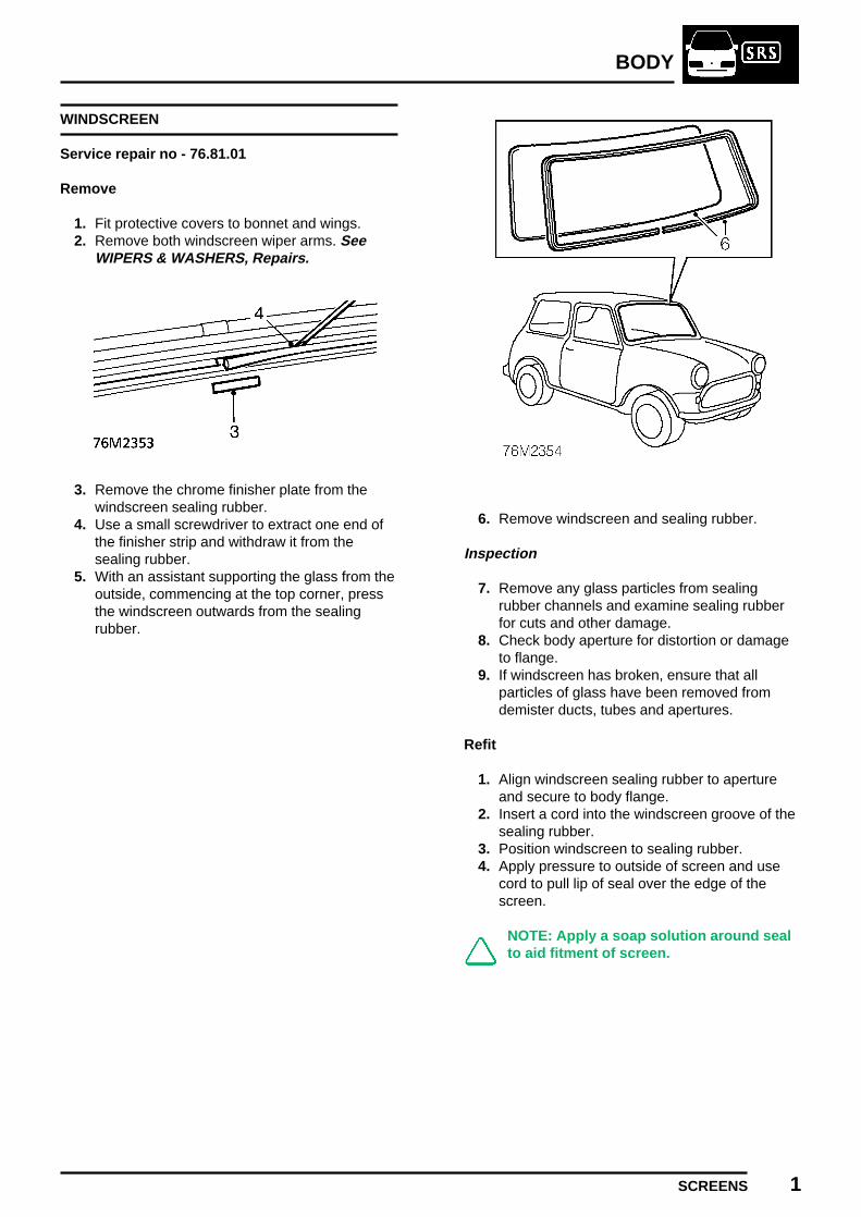
BODY
SCREENS 1
WINDSCREEN
Service repair no - 76.81.01
Remove
1. Fit protective covers to bonnet and wings.2. Remove both windscreen wiper arms. See
WIPERS & WASHERS, Repairs.
3. Remove the chrome finisher plate from thewindscreen sealing rubber.
4. Use a small screwdriver to extract one end ofthe finisher strip and withdraw it from thesealing rubber.
5. With an assistant supporting the glass from theoutside, commencing at the top corner, pressthe windscreen outwards from the sealingrubber.
6. Remove windscreen and sealing rubber.
Inspection
7. Remove any glass particles from sealingrubber channels and examine sealing rubberfor cuts and other damage.
8. Check body aperture for distortion or damageto flange.
9. If windscreen has broken, ensure that allparticles of glass have been removed fromdemister ducts, tubes and apertures.
Refit
1. Align windscreen sealing rubber to apertureand secure to body flange.
2. Insert a cord into the windscreen groove of thesealing rubber.
3. Position windscreen to sealing rubber.4. Apply pressure to outside of screen and use
cord to pull lip of seal over the edge of thescreen.
NOTE: Apply a soap solution around sealto aid fitment of screen.

BODY
2 SCREENS
5. Thread end of the finisher strip through the eyeof tool 18G 468B and under the roller.
6. Starting at the top centre of the windscreensealing rubber, insert eye of tool into finisherstrip groove.
7. Slowly push tool around entire length of sealingrubber, feeding the finisher strip into the grooveas the eyelet on the tool opens it and use theroller to bed it into the seal.
8. Remove tool 18G 468B and fit chrome finisherplate into sealing rubber to cover the ends ofthe finisher strip.
9. Clean windscreen.10. Fit windscreen wiper arms. See WIPERS &
WASHERS, Repairs.11. Remove protective covers from bonnet and
wings.

BODY
SEATS AND SEAT BELTS 1ISSUED: 12/96
FRONT SEAT BELT
Service repair no - 76.73.31
Remove
The front seat belt and pre-tensioner can only berenewed as an assembly, refer to Front seat beltpre-tensioner. See RESTRAINT SYSTEMS,Repairs.
FRONT SEAT
Service repair no - 78.10.44.99
Remove
1. Raise lever and slide seat fully rearwards.2. Remove 2 nuts and bolts securing seat to
mounting brackets.3. Pull rear seat access lever to release seat from
floor and remove seat.
Refit
1. Position seat in vehicle.2. Align seat to mounting brackets.3. Fit nuts and bolts securing seat to mounting
brackets and tighten to 25 Nm.
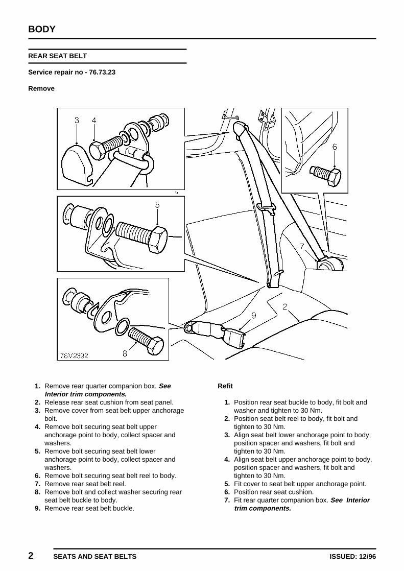
BODY
2 SEATS AND SEAT BELTS ISSUED: 12/96
REAR SEAT BELT
Service repair no - 76.73.23
Remove
1. Remove rear quarter companion box. SeeInterior trim components.
2. Release rear seat cushion from seat panel.3. Remove cover from seat belt upper anchorage
bolt.4. Remove bolt securing seat belt upper
anchorage point to body, collect spacer andwashers.
5. Remove bolt securing seat belt loweranchorage point to body, collect spacer andwashers.
6. Remove bolt securing seat belt reel to body.7. Remove rear seat belt reel.8. Remove bolt and collect washer securing rear
seat belt buckle to body.9. Remove rear seat belt buckle.
Refit
1. Position rear seat buckle to body, fit bolt andwasher and tighten to 30 Nm.
2. Position seat belt reel to body, fit bolt andtighten to 30 Nm.
3. Align seat belt lower anchorage point to body,position spacer and washers, fit bolt andtighten to 30 Nm.
4. Align seat belt upper anchorage point to body,position spacer and washers, fit bolt andtighten to 30 Nm.
5. Fit cover to seat belt upper anchorage point.6. Position rear seat cushion.7. Fit rear quarter companion box. See Interior
trim components.

BODY
SEATS AND SEAT BELTS 3ISSUED: 12/96
REAR SEAT SQUAB
Service repair no - 78.10.56.99
Remove
1. Remove rear seat cushion. See this section.2. Open luggage compartment.
3. Remove 2 screws securing seat squab tobody.
4. Pull seat belt harnesses away from squab.5. Release and remove rear seat squab.
Refit
1. Position rear seat squab in vehicle.2. Ensure seat belts are routed over squab.3. Fit and tighten screws securing squab to body.4. Fit rear seat cushion. See this section.
REAR SEAT CUSHION
Service repair no - 78.40.29
Remove
1. Release rear seat cushion from seat panel.2. Remove 2 screws securing cushion straps to
body.3. Remove rear seat cushion.
Refit
1. Position rear seat cushion in vehicle.2. Align cushion straps to body and secure with
screws.3. Position seat cushion on seat panel.


HEATING & VENTILATION
CONTENTS Page
REPAIRS
HEATER VALVE CONTROL CABLE 1.......................................................................HEATER VALVE 2.......................................................................................................HEATER FAN SWITCH 4............................................................................................HEATER UNIT 4..........................................................................................................HEATER MOTOR AND FAN 6....................................................................................RESISTOR UNIT 7......................................................................................................HEATER MATRIX 8.....................................................................................................


HEATING & VENTILATION
REPAIRS 1ISSUED: 12/96
HEATER VALVE CONTROL CABLE
Service repair no - 80.10.07
Remove
1. Disconnect battery earth lead.
2. Remove 2 screws securing heater to lowerfascia rail.
3. Remove nut securing heater valve to fasciarail.
NOTE: An earth lead is located on theheater valve stud.
4. Remove clip securing control cable to heatervalve.
5. Disconnect control cable from lever on valve.
6. Remove 2 nuts securing switch panel to lowerfascia rail.
7. Release switch panel from fascia rail.8. Remove nut securing control cable to switch
panel.9. Remove heater control cable.

HEATING & VENTILATION
2 REPAIRS ISSUED: 12/96
Refit
1. Fit heater control cable to switch panel andsecure with nut.
2. Feed the cable over the top of the heater.3. Ensure cable is routed correctly and heater
valve is in the OFF position.4. Connect control cable to lever on heater valve
and secure with clip.5. Check that heater valve control lever operates
through its full range of travel, adjust position ofouter cable if necessary.
6. Fit switch panel to fascia rail and secure withnuts.
7. Align heater to fascia rail and secure withscrews.
8. Fit heater valve to fascia support rail, fit earthlead to heater valve stud and tighten nut.
9. Connect battery earth lead.
HEATER VALVE
Service repair no - 80.10.16
Remove
1. Drain cooling system. See COOLINGSYSTEM, Adjustments.
2. Position container beneath heater to collectcoolant spillage.
3. Disconnect demister duct from heater.4. Release clip securing feed hose to heater.5. Disconnect hose from heater.6. Ensure heater valve is in the open position and
allow coolant to drain.7. Remove nut securing heater valve to fascia
rail.
NOTE: An earth lead is located on theheater valve stud.

HEATING & VENTILATION
REPAIRS 3ISSUED: 12/96
8. Lower heater valve to gain access to heaterhose.
9. Release clip and disconnect heater hose fromvalve.
10. Remove clip securing heater control cable tovalve.
11. Disconnect control cable from lever on valve.12. Remove heater valve. 13. Release clip and remove hose from heater
valve.
Refit
1. Fit heater hose to valve and secure with clip.2. Position heater valve to fascia support rail.3. Connect hose to heater valve and secure with
clip.4. Connect heater control cable to lever on valve
and secure with clip.5. Fit heater valve to fascia support rail, fit earth
lead to heater valve stud and tighten nut.6. Connect hose to heater and secure with clip.7. Connect demister duct to heater.8. Remove container to collect coolant spillage
from heater.9. Refill cooling system. See COOLING
SYSTEM, Adjustments.
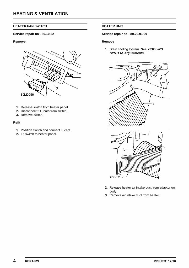
HEATING & VENTILATION
4 REPAIRS ISSUED: 12/96
HEATER FAN SWITCH
Service repair no - 80.10.22
Remove
1. Release switch from heater panel.2. Disconnect 2 Lucars from switch.3. Remove switch.
Refit
1. Position switch and connect Lucars.2. Fit switch to heater panel.
HEATER UNIT
Service repair no - 80.20.01.99
Remove
1. Drain cooling system. See COOLINGSYSTEM, Adjustments.
2. Release heater air intake duct from adaptor onbody.
3. Remove air intake duct from heater.
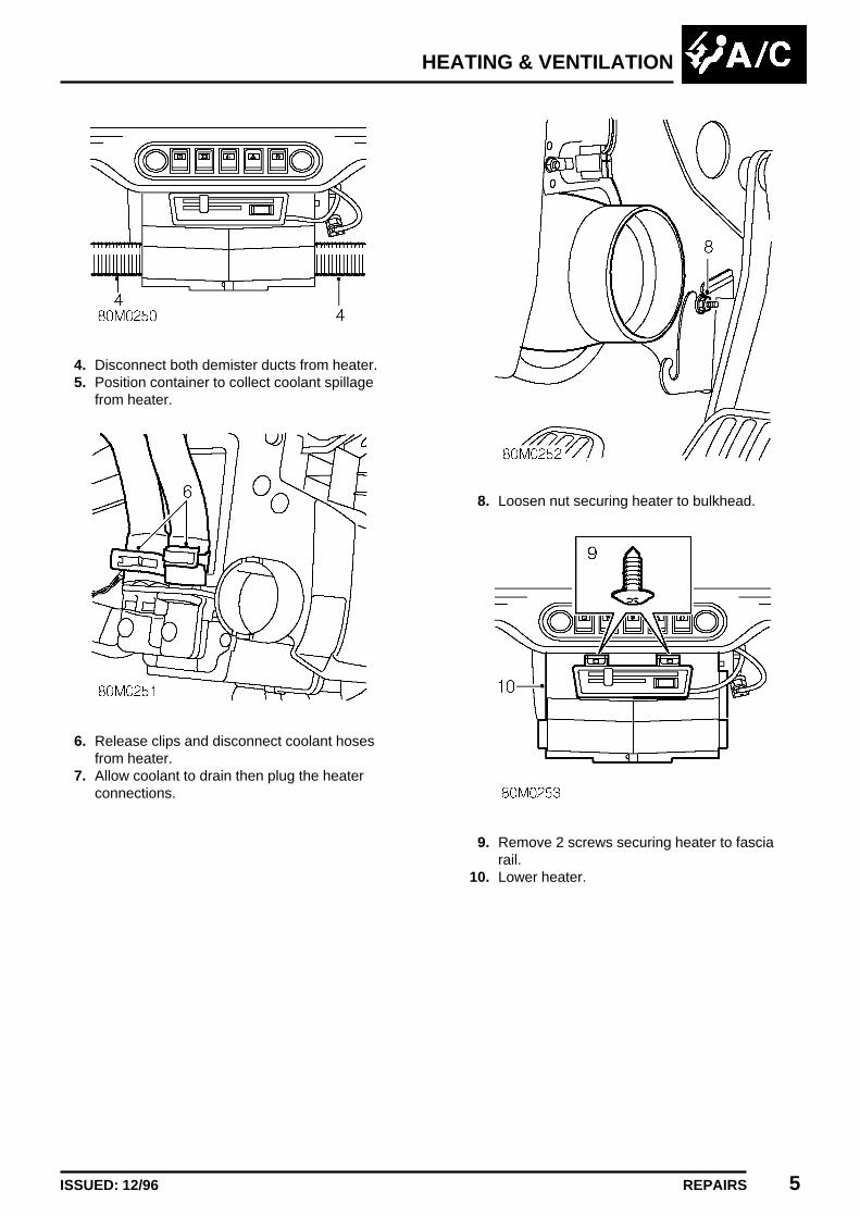
HEATING & VENTILATION
REPAIRS 5ISSUED: 12/96
4. Disconnect both demister ducts from heater.5. Position container to collect coolant spillage
from heater.
6. Release clips and disconnect coolant hosesfrom heater.
7. Allow coolant to drain then plug the heaterconnections.
8. Loosen nut securing heater to bulkhead.
9. Remove 2 screws securing heater to fasciarail.
10. Lower heater.
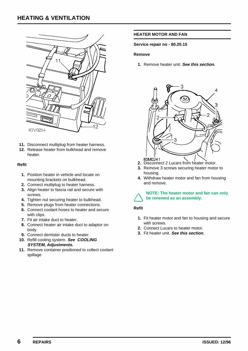
HEATING & VENTILATION
6 REPAIRS ISSUED: 12/96
11. Disconnect multiplug from heater harness.12. Release heater from bulkhead and remove
heater.
Refit
1. Position heater in vehicle and locate onmounting brackets on bulkhead.
2. Connect multiplug to heater harness.3. Align heater to fascia rail and secure with
screws.4. Tighten nut securing heater to bulkhead.5. Remove plugs from heater connections.6. Connect coolant hoses to heater and secure
with clips.7. Fit air intake duct to heater.8. Connect heater air intake duct to adaptor on
body.9. Connect demister ducts to heater.
10. Refill cooling system. See COOLINGSYSTEM, Adjustments.
11. Remove container positioned to collect coolantspillage
HEATER MOTOR AND FAN
Service repair no - 80.20.15
Remove
1. Remove heater unit. See this section.
2. Disconnect 2 Lucars from heater motor.3. Remove 3 screws securing heater motor to
housing.4. Withdraw heater motor and fan from housing
and remove.
NOTE: The heater motor and fan can onlybe renewed as an assembly.
Refit
1. Fit heater motor and fan to housing and securewith screws.
2. Connect Lucars to heater motor.3. Fit heater unit. See this section.

HEATING & VENTILATION
REPAIRS 7ISSUED: 12/96
RESISTOR UNIT
Service repair no - 80.20.17
Remove
1. Release heater air intake duct from adaptor onbody.
2. Remove air intake duct from heater.
3. Disconnect both demister ducts from heater.4. Remove 2 screws securing heater to fascia
rail.
5. Loosen nut securing heater to bulkhead.6. Lower heater.

HEATING & VENTILATION
8 REPAIRS ISSUED: 12/96
7. Disconnect multiplug from resistor unit.8. Remove 2 nuts securing resistor unit to heater.9. Remove resistor unit.
Refit
1. Fit resistor unit to heater and secure with nuts.2. Connect multiplug to resistor unit.3. Align heater to fascia rail and secure with
screws.4. Tighten nut securing heater to bulkhead.5. Fit air intake duct to heater.6. Connect heater air intake duct to adaptor on
body.7. Connect demister ducts to heater.
HEATER MATRIX
Service repair no - 80.20.29
Remove
1. Remove heater unit. See this section.
2. Remove 2 screws securing heater matrixend-plate to housing.
3. Withdraw heater matrix from housing.4. Remove 4 screws securing heater pipe clamp
plates to matrix.5. Remove 2 heater pipe clamp plates.6. Remove heater pipes from matrix.7. Remove and discard ’O’ rings from heater
pipes.
Refit
1. Lubricate new ’O’ rings and fit to heater pipes.2. Fit heater pipes to matrix.3. Fit heater pipe clamp plates and secure with
screws.4. Insert matrix into heater and secure with
screws.5. Fit heater unit. See this section.
WIPERS & WASHERS
CONTENTS Page
REPAIRS
WASHER TUBE 1........................................................................................................WIPER ARM 3.............................................................................................................WINDSCREEN WIPER MOTOR 3..............................................................................WINDSCREEN WIPER WHEEL BOX AND CABLE RACK TUBE 5...........................WINDSCREEN WASHER AND WIPER SWITCH 7....................................................DELAY UNIT 8.............................................................................................................


WIPERS & WASHERS
REPAIRS 1REVISED: 12/96
WASHER TUBE
Service repair no - 84.10.15
Remove
1. Disconnect washer tube from ’T’ connectorunderbonnet.
2. Release sound deadening pad from bulkhead.
3. Remove locking ring securing RH air vent tofascia.
4. Release and remove air vent from fascia.5. Remove air vent tube.6. Release sound deadening pad from bulkhead.
7. Withdraw washer tube through grommet inbulkhead.
8. Attach draw string to washer tube and securewith tape.

WIPERS & WASHERS
2 REPAIRS ISSUED: 12/96
9. Remove foam strip from between body panelsin boot.
10. Release washer tube from clip on body.11. Disconnect washer tube from one-way. valve.12. Pull tube through body into boot space.13. Remove tape securing draw string to washer
tube.14. Remove washer tube.
Refit
1. Measure and cut new length of washer tube.2. Attach washer tube to draw string and secure
with tape.3. Using assistance feed/draw washer tube
through body.4. Remove tape securing draw string to washer
tube and remove draw string.5. Connect washer tube to one-way valve.6. Secure washer tube to clip on body and fit
foam strip between body panels.7. Pass tube through grommet in bulkhead into
engine compartment.8. Secure sound deadening pad to bulkhead.9. Fit air vent tube.
10. Fit air vent to fascia and secure with lockingring.
11. Secure sound deadening pad to bulkheadunderbonnet.
12. Connect washer tube to ’T’ connector.13. Top up washer reservoir.

WIPERS & WASHERS
REPAIRS 3ISSUED: 12/96
WIPER ARM
Service repair no - 84.15.01
Remove
1. Carefully lever wiper arm from splines onwheelbox spindle using a flat bladedscrewdriver.
2. Remove wiper arm from wheelbox spindle.
3. Press clip and remove wiper blade from arm.
Refit
1. Fit wiper blade to arm.2. Align wiper arm to screen and push onto
wheelbox spindle.
WINDSCREEN WIPER MOTOR
Service repair no - 84.15.12
Remove
1. Disconnect battery earth lead.2. Remove both windscreen wiper arms. See this
section.
3. Remove ’E’ clip securing emission canisterpipe to mounting bracket.
4. Release emission canister pipe from mountingbracket.
5. Remove 2 bolts securing emission canisterpurge valve to body.
6. Position purge valve aside.

WIPERS & WASHERS
4 REPAIRS ISSUED: 12/96
7. Disconnect earth lead from wiper motor.8. Loosen nut securing cable rack tube to wiper
motor.9. Remove 2 screws securing wiper motor calmp
to body and remove clamp.
10. Disconnect multiplug from wiper motor.11. Remove wiper motor complete with cable rack.12. Collect wiper motor mounting pad.
Do not carry out further dismantling ifcomponent is removed for access only.
13. Remove 4 bolts securing cover to wiper motorgearbox.
14. Remove cover from wiper motor gearbox.Note position of earth lead lug.
15. Remove circlip and washer securing cable rackconnecting rod to wiper motor crank.
16. Remove connecting rod and cable rackassembly.
17. Collect flat washer from under cable rackconnecting rod.
18. Fit flat washer to wiper motor crank.19. Fit cable rack connecting rod to wiper motor
crank and secure with flat washer and circlip.20. Position cover and earth lead lug to wiper
motor gearbox and secure with screws.

WIPERS & WASHERS
REPAIRS 5ISSUED: 12/96
Refit
1. Position wiper motor mounting pad to body.2. Lubricate wiper motor cable rack.3. Feed cable rack into tube, ensuring the rack
engages with the wheelbox teeth.4. Position wiper motor to mounting pad.5. Connect multiplug to wiper motor.6. Position wiper motor retaining strap and secure
with screws.7. Tighten nut securing cable rack tube to wiper
motor.8. Connect earth lead to wiper motor.9. Position emission canister purge valve to body,
fit bolts and tighten to 9 Nm.10. Connect emission canister pipe to purge valve
and secure with ’E’ clip.11. Fit wiper arms. See this section.12. Connect battery earth lead.
WINDSCREEN WIPER WHEEL BOX AND CABLERACK TUBE
Service repair no - 84.15.27
Remove
1. Remove windscreen wiper motor. See thissection.
2. Remove air cleaner. See ENGINEMANAGEMENT SYSTEM - MEMS, Repairs.
3. Disconnect washer tube from washer jets.4. Remove 2 nuts securing wiper wheel boxes to
body.5. Remove rubber spacers from wheel boxes.

WIPERS & WASHERS
6 REPAIRS ISSUED: 12/96
6. Release engine management relay modulefrom mounting bracket and position aside.
7. Release wheel boxes from body.
8. Rotate wheel box and cable rack tubeassembly and remove from vehicle.
9. Collect 2 rubber spacers.
10. Loosen nuts securing wiper wheel boxes tocable rack tube.
11. Remove wiper wheel boxes.
Refit
1. Lubricate wheel box gears and spindles.2. Fit wheel boxes to cable rack tube but do not
tighten securing nuts.3. Fit rubber spacers to wheel box spindles.4. Position wheel box and cable rack tube
assembly to body.5. Fit rubber spacers to wheel box spindles, fit
nuts and tighten to 10 Nm.6. Secure engine management relay module to
mounting bracket.7. Fit wiper motor. See this section.8. Operate wiper motor and check that wipers
move smoothly across screen.9. Tighten nuts securing wheel boxes to cable
rack tube.10. Connect washer tube to washer jets.11. Fit air cleaner. See ENGINE MANAGEMENT
SYSTEM - MEMS, Repairs.

WIPERS & WASHERS
REPAIRS 7ISSUED: 12/96
WINDSCREEN WASHER AND WIPER SWITCH
Service repair no - 84.15.34
Remove
1. Remove rotary coupler. See ELECTRICAL,Repairs.
2. Disconnect multiplug from switch.
3. Remove 2 screws securing switch to switchassembly
4. Depress retaining tag and remove switch.
Refit
1. Fit windscreen washer and wiper switch toswitch assembly and secure with screws.
2. Connect multiplug to switch.3. Fit rotary coupler. See ELECTRICAL,
Repairs.

WIPERS & WASHERS
8 REPAIRS ISSUED: 12/96
DELAY UNIT
Service repair no - 84.15.36
Remove
1. Remove fascia panel. See BODY, Interiortrim components.
2. Release delay unit multiplug from mountingbracket.
3. Remove delay unit from multiplug.
Refit
1. Fit delay unit to multiplug and secure multiplugto mounting bracket.
2. Fit fascia panel. See BODY, Interior trimcomponents.

ELECTRICAL
CONTENTS Page
DESCRIPTION AND OPERATION
ELECTRICAL CONTROL UNIT LOCATIONS 1..........................................................
ADJUSTMENTSAUXILIARY DRIVE BELT 1.........................................................................................HEADLAMP ADJUST 2...............................................................................................
REPAIRSALTERNATOR 1..........................................................................................................AUXILIARY DRIVE BELT 2.........................................................................................ALTERNATOR PULLEY 2...........................................................................................AUXILIARY DRIVE BELT TENSIONER 3...................................................................HORN 4.......................................................................................................................HEADLAMP 5..............................................................................................................FRONT INDICATOR LAMP 6......................................................................................SIDE REPEATER LAMP 6..........................................................................................TAIL LAMP 7...............................................................................................................FOG OR DRIVING LAMP 9.........................................................................................HEADLAMP ADJUSTER UNIT 9.................................................................................RADIO 10....................................................................................................................REAR SPEAKER 11....................................................................................................AERIAL 11...................................................................................................................COAXIAL CABLE 12....................................................................................................HORN RELAY 14.........................................................................................................DIRECTION INDICATOR RELAY 14...........................................................................FOG/DRIVING LAMP RELAY 15.................................................................................AUXILIARY CIRCUITS RELAY 15..............................................................................FLASHER UNIT 16......................................................................................................ANTI THEFT ALARM - ECU 16...................................................................................STARTER MOTOR 17.................................................................................................HEADLAMP LEVELLING SWITCH 18........................................................................DRIVING/FOG LAMP SWITCH 19..............................................................................HEATED REAR SCREEN SWITCH 20.......................................................................HAZARD WARNING LIGHT SWITCH 21....................................................................INDICATOR/HEADLAMP SWITCH 22........................................................................STEERING COLUMN SWITCH ASSEMBLY 22..........................................................REAR FOG LAMP SWITCH 24...................................................................................ROTARY COUPLER 25...............................................................................................ENGINE COMPARTMENT FUSE BOX 26..................................................................PASSENGER COMPARTMENT FUSE BOX 27.........................................................CD PLAYER 28...........................................................................................................

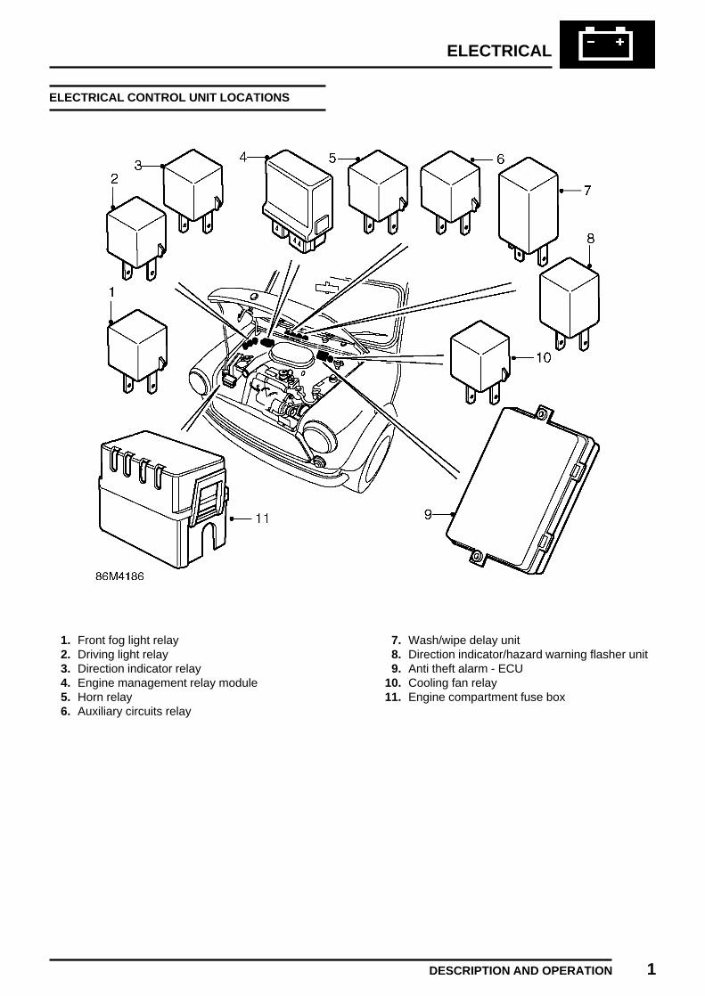
ELECTRICAL
DESCRIPTION AND OPERATION 1
ELECTRICAL CONTROL UNIT LOCATIONS
1. Front fog light relay2. Driving light relay3. Direction indicator relay4. Engine management relay module5. Horn relay6. Auxiliary circuits relay
7. Wash/wipe delay unit8. Direction indicator/hazard warning flasher unit9. Anti theft alarm - ECU
10. Cooling fan relay11. Engine compartment fuse box


ELECTRICAL
ADJUSTMENTS 1REVISED: 06/99
AUXILIARY DRIVE BELT
Service repair no - 86.10.05
Check
1. Remove nut and bolt securing auxiliary drivebelt cover.
2. Remove auxiliary drive belt cover.3. Check condition of drive belt, renew a drive
belt that shows signs of wear and splitting.
4. Apply a force of 10 kg to the drive belt atposition ’X’ and measure the deflectionbetween the crankshaft pulley and alternatorpulley.Deflection must be 6 - 8 mm.
Adjust
1. Loosen tensioner pulley retaining nut.2. Increase drive belt tension by turning the
tension adjusting bolt clockwise.
CAUTION: Do not apply excessive torqueto adjusting bolt or damage to bolt willresult. If bolt appears to be seized or is
difficult to turn, apply suitable anti-seizelubricant to bolt.
3. Tighten tensioner pulley retaining nut to 25Nm.
4. Recheck drive belt tension.5. Fit auxiliary drive belt cover and secure with
nut and bolt.

ELECTRICAL
2 ADJUSTMENTS REVISED: 12/96
HEADLAMP ADJUST
Service repair no - 86.40.17
Inspect
1. Align suitable beam setting equipment toheadlamp.
2. Ensure headlamp levelling switch is in position’0’ and switch on headlamps.Headlamp setting = 1.4% below horizontal andparallel.
Adjust
1. Remove screw securing headlamp finisher andremove.
2. Turn screws for vertical alignment.3. Turn screw for horizontal alignment.4. Fit headlamp finisher and secure with screw.5. Align beam setting equipment to 2nd
headlamp.6. Adjust 2nd headlamp as detailed in steps 1 to
3 above.7. Switch off headlamps.8. Remove beam setter.

ELECTRICAL
REPAIRS 1
ALTERNATOR
Service repair no - 86.10.02
Remove
1. Remove auxiliary drive belt. See this section.
2. Remove 2 nuts and disconnect leads fromalternator.
3. Remove 2 bolts and nut and bolt securingalternator.
4. Remove alternator.
5. Hold alternator shaft with an 8 mm Allen keyand remove pulley retaining nut with 18G 1653.
6. Remove alternator pulley.
Refit
1. Clean mating face of alternator pulley andshaft.
2. Fit pulley to alternator and tighten nut to 25Nm.
3. Fit alternator.4. Fit and tighten bolts and nut and bolt securing
alternator.5. Connect leads to alternator and tighten nuts.6. Fit auxiliary drive belt. See this section.

ELECTRICAL
2 REPAIRS REVISED: 06/99
AUXILIARY DRIVE BELT
Service repair no - 86.10.03
Remove
1. Disconnect battery earth lead.2. Remove nut and bolt securing drive belt cover
and remove cover.
3. Loosen tensioner pulley retaining nut.4. Release drive belt tension by turning the
tension adjusting bolt clockwise and removedrive belt.
CAUTION: Do not apply excessive torqueto adjusting bolt or damage to bolt willresult. If bolt appears to be seized or is
difficult to turn, apply suitable anti-seizelubricant to bolt.
Refit
1. Clean pulleys.2. Fit new drive belt to pulleys. Ensure grooves
on pulleys and drive belt are correctly located.3. Adjust drive belt tension. See Adjustments.4. Connect battery earth lead.
ALTERNATOR PULLEY
Service repair no - 86.10.04
Remove
1. Remove auxiliary drive belt. See this section.
2. Hold alternator shaft with an 8 mm Allen keyand remove pulley retaining nut with 18G 1653.
3. Remove alternator pulley.
Refit
1. Clean mating face of alternator pulley andshaft.
2. Fit pulley to alternator and tighten nut to 25Nm.
3. Fit auxiliary drive belt. See this section.
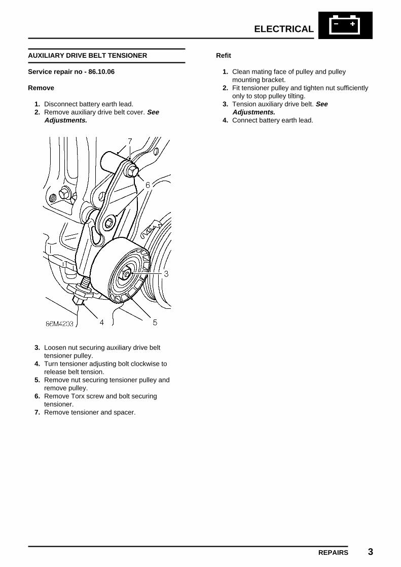
ELECTRICAL
REPAIRS 3
AUXILIARY DRIVE BELT TENSIONER
Service repair no - 86.10.06
Remove
1. Disconnect battery earth lead.2. Remove auxiliary drive belt cover. See
Adjustments.
3. Loosen nut securing auxiliary drive belttensioner pulley.
4. Turn tensioner adjusting bolt clockwise torelease belt tension.
5. Remove nut securing tensioner pulley andremove pulley.
6. Remove Torx screw and bolt securingtensioner.
7. Remove tensioner and spacer.
Refit
1. Clean mating face of pulley and pulleymounting bracket.
2. Fit tensioner pulley and tighten nut sufficientlyonly to stop pulley tilting.
3. Tension auxiliary drive belt. SeeAdjustments.
4. Connect battery earth lead.

ELECTRICAL
4 REPAIRS REVISED: 12/96
HORN
Service repair no - 86.30.10
Remove
1. Disconnect multiplug from horn.2. Remove 2 bolts securing horn mounting
bracket to body.3. Remove horn and mounting bracket.
4. Remove nut and washer securing horn tomounting bracket.
5. Remove horn.
Refit
1. Fit horn to mounting bracket.2. Fit nut and washer securing horn to mounting
bracket and tighten to 10 Nm.3. Align horn mounting bracket to body, fit bolts
and tighten to 9 Nm.4. Connect multiplug to horn.

ELECTRICAL
REPAIRS 5REVISED: 12/96
HEADLAMP
Service repair no - 86.40.27
Remove
1. Remove screw securing headlamp finisher andremove finisher.
2. Release headlamp unit from RH retainingscrew and levelling pivot.
3. Pull unit forward and disconnect headlampbulb multiplug and pilot lamp bulb.
4. Remove headlamp.5. Release clip securing bulb to headlamp and
remove bulb.
Refit
1. Fit bulb to headlamp and secure with clip.2. Position headlamp unit, connect pilot lamp bulb
and multiplug. Secure bulb cover.3. Position headlamp unit to levelling pivot and
secure to retaining screws.4. Fit headlamp finisher and tighten screw.

ELECTRICAL
6 REPAIRS
FRONT INDICATOR LAMP
Service repair no - 86.40.42
Remove
1. Remove 2 screws securing lamp to body.2. Release lamp and disconnect bulb holder.
Refit
1. Connect bulb holder to lamp.2. Position lamp to body and secure with screws.
SIDE REPEATER LAMP
Service repair no - 86.40.51
Remove
1. Squeeze lugs on repeater lamp to release fromwing.
2. Release bulb holder from repeater lamp.
Refit
1. Connect bulb holder to repeater lamp.2. Fit repeater lamp to wing.
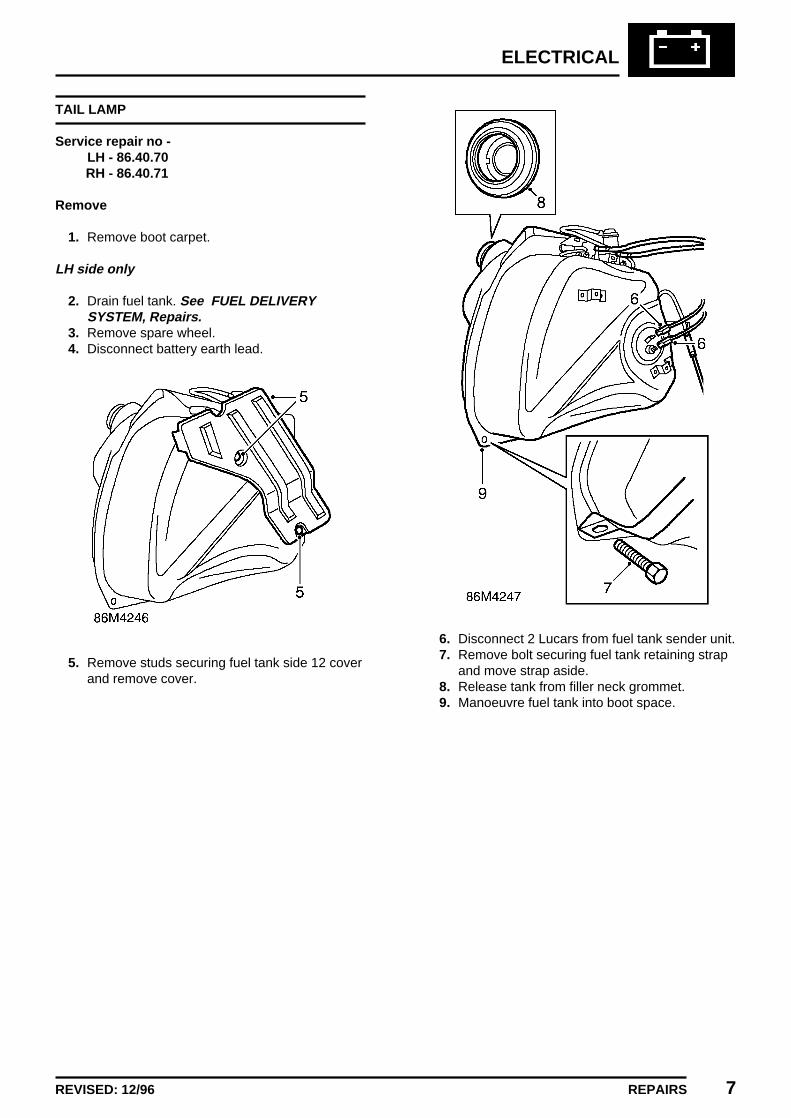
ELECTRICAL
REPAIRS 7REVISED: 12/96
TAIL LAMP
Service repair no -LH - 86.40.70RH - 86.40.71
Remove
1. Remove boot carpet.
LH side only
2. Drain fuel tank. See FUEL DELIVERYSYSTEM, Repairs.
3. Remove spare wheel.4. Disconnect battery earth lead.
5. Remove studs securing fuel tank side 12 coverand remove cover.
6. Disconnect 2 Lucars from fuel tank sender unit.7. Remove bolt securing fuel tank retaining strap
and move strap aside.8. Release tank from filler neck grommet.9. Manoeuvre fuel tank into boot space.

ELECTRICAL
8 REPAIRS REVISED: 12/96
Both sides
10. Disconnect multiplug from tail lamp.11. Disconnect Lucar from tail lamp.12. Remove 4 nuts securing tail lamp to body.13. Disconnect earth lead(s) from stud.14. Remove tail lamp assembly.15. Remove tail lamp seal.
Refit
1. Fit seal to tail lamp.2. Clean mating faces of tail lamp and body.3. Fit tail lamp assembly to body, fit earth lead(s)
to stud.4. Fit nuts securing tail lamp to body and tighten
to 9 Nm.5. Connect multiplug to tail lamp.
LH side only
6. Manoeuvre fuel tank into position and positionrestraining strap.
7. Fit and tighten strap retaining bolt.8. Connect Lucars to sender unit.9. Fit fuel tank side cover and secure with studs.
10. Position spare wheel11. Fit boot carpet.12. Refill fuel tank with fuel.13. Connect battery earth lead.

ELECTRICAL
REPAIRS 9REVISED: 12/96
FOG OR DRIVING LAMP
Service repair no - 86.40.96
Remove
1. Remove front grille. See BODY, Exteriorfittings.
2. Disconnect multiplug from lamp.3. Release cable tie securing harness to body.4. Remove bolt securing lamp to mounting
bracket and remove lamp.
Refit
1. Position lamp to mounting bracket, fit andtighten bolt.
2. Connect multiplug to lamp and secure harnessto body with cable tie.
3. Fit front grille. See BODY, Exterior fittings.
HEADLAMP ADJUSTER UNIT
Service repair no - 86.41.16
Remove
1. Remove headlamp light unit. See this section.2. Raise front of vehicle.
WARNING: Support on safety stands.
3. Locate headlamp adjuster under wing and pullback multiplug cover. Disconnect multiplug.
4. Rotate adjuster clockwise and release fromheadlamp.
Refit
1. Position adjuster to headlamp and rotate toposition.
2. Connect multiplug to adjuster and securecover.
3. Fit headlamp light unit. See this section.4. Remove stand(s) and lower vehicle.

ELECTRICAL
10 REPAIRS REVISED: 12/96
RADIO
Service repair no - 86.50.03
Remove
1. Fit radio removal tools SMD 4091 to releaseretaining clips. Pull on tools to release radiofrom fascia.
2. Disconnect 2 multiplugs and aerial lead fromradio.
3. Remove radio and remove tools from radio.
Refit
1. Position radio to aperture. Connect multiplugsand aerial lead.
2. Slide radio into fascia until retaining clipsengage.
3. Enter security code and check radio for correctoperation.
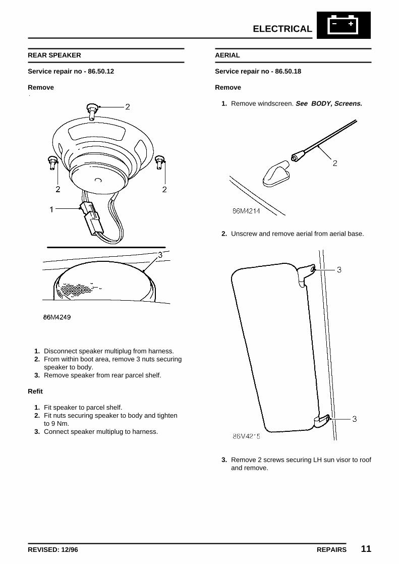
ELECTRICAL
REPAIRS 11REVISED: 12/96
REAR SPEAKER
Service repair no - 86.50.12
Remove
1. Disconnect speaker multiplug from harness.2. From within boot area, remove 3 nuts securing
speaker to body.3. Remove speaker from rear parcel shelf.
Refit
1. Fit speaker to parcel shelf.2. Fit nuts securing speaker to body and tighten
to 9 Nm.3. Connect speaker multiplug to harness.
AERIAL
Service repair no - 86.50.18
Remove
1. Remove windscreen. See BODY, Screens.
2. Unscrew and remove aerial from aerial base.
3. Remove 2 screws securing LH sun visor to roofand remove.

ELECTRICAL
12 REPAIRS REVISED: 12/96
4. Release roof lining from front upper flange ofwindscreen aperture.
5. Carefully lower front edge of roof lining to gainaccess to aerial.
6. Remove cover from coaxial cable.7. Remove nut securing coaxial cable to aerial
base.8. Remove aerial base from roof.
Refit
1. Clean mating face of aerial base and vehicleroof.
2. Fit aerial base to roof.3. Connect coaxial cable to aerial base.4. Fit nut securing coaxial cable to aerial base
and tighten to 9 Nm.5. Fit cover to coaxial cable.6. Apply adhesive to edge of roof lining and
carefully secure to windscreen aperture.7. Position LH sun visor and secure with screws.8. Fit windscreen. See BODY, Screens.
COAXIAL CABLE
Service repair no - 86.50.24
Remove
1. Remove fascia. See BODY, Interior trimcomponents.
2. Remove windscreen. See BODY, Screens.
3. Remove 2 screws securing LH sun visor toroof.

ELECTRICAL
REPAIRS 13REVISED: 12/96
4. Release roof lining from front upper flange ofwindscreen aperture.
5. Carefully lower front edge of roof lining to gainaccess to aerial.
6. Remove cover from coaxial cable.7. Remove nut securing coaxial cable to aerial
base.
8. Remove 3 cable ties securing coaxial cable tobody harness.
9. Tie a draw string to the radio end of the coaxialcable and withdraw cable into roof area.
10. Untie draw string and remove coaxial cable.
Refit
1. Attach draw string to the radio end of the newcoaxial cable and pull cable into position.
2. Remove draw string.3. Secure coaxial cable to main harness with
cable ties.4. Connect coaxial cable to aerial base.5. Fit nut securing coaxial cable to aerial base
and tighten to 9 Nm.6. Fit cover to coaxial cable.7. Apply adhesive to edge of roof lining and
carefully secure to windscreen aperture.8. Position LH sun visor and secure with screws.9. Fit windscreen. See BODY, Screens.
10. Fit fascia. See BODY, Interior trimcomponents.
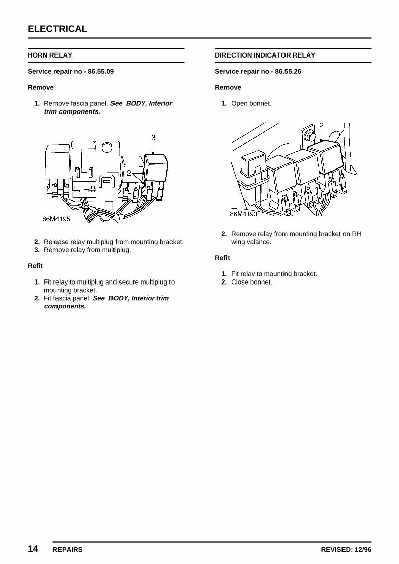
ELECTRICAL
14 REPAIRS REVISED: 12/96
HORN RELAY
Service repair no - 86.55.09
Remove
1. Remove fascia panel. See BODY, Interiortrim components.
2. Release relay multiplug from mounting bracket.3. Remove relay from multiplug.
Refit
1. Fit relay to multiplug and secure multiplug tomounting bracket.
2. Fit fascia panel. See BODY, Interior trimcomponents.
DIRECTION INDICATOR RELAY
Service repair no - 86.55.26
Remove
1. Open bonnet.
2. Remove relay from mounting bracket on RHwing valance.
Refit
1. Fit relay to mounting bracket.2. Close bonnet.

ELECTRICAL
REPAIRS 15REVISED: 12/96
FOG/DRIVING LAMP RELAY
Service repair no - 86.55.51
Remove
1. Open bonnet.
Driving lamp relay
Fog lamp relay
2. Remove relay from mounting bracket on RHwing valance.
Refit
1. Fit relay to mounting bracket.2. Close bonnet.
AUXILIARY CIRCUITS RELAY
Service repair no - 86.55.52
Remove
1. Remove fascia panel. See BODY, Interiortrim components.
2. Release relay multiplug from mounting bracket.3. Remove relay from multiplug.
Refit
1. Fit relay to multiplug and secure multiplug tomounting bracket.
2. Fit fascia panel. See BODY, Interior trimcomponents.

ELECTRICAL
16 REPAIRS REVISED: 12/96
FLASHER UNIT
Service repair no - 86.55.68
Remove
1. Remove fascia panel. See BODY, Interiortrim components.
2. Release flasher unit multiplug from mountingbracket.
3. Remove flasher unit from multiplug.
Refit
1. Fit flasher unit to multiplug and securemultiplug to mounting bracket.
2. Fit fascia panel. See BODY, Interior trimcomponents.
ANTI THEFT ALARM - ECU
Service repair no - 86.55.85
Remove
1. Remove fascia panel. See BODY, Interiortrim components.
2. Disconnect multiplug from anti theft alarmECU.
3. Remove 2 screws securing ECU to mountingbracket.
4. Remove ECU.
Refit
1. Fit ECU to mounting bracket.2. Fit and tighten screws.3. Connect multiplug.4. Fit fascia panel. See BODY, Interior trim
components.

ELECTRICAL
REPAIRS 17REVISED: 12/96
STARTER MOTOR
Service repair no - 86.60.01
Remove
1. Disconnect battery earth lead.2. Raise front of vehicle.
WARNING: Support on safety stands.
3. Remove front grille. See BODY, Exteriorfittings.
4. Remove 4 bolts securing radiator uppermountings to bonnet platform.
5. Remove radiator from its lower mountings andmove it to LH side for access to starter motor.
6. Remove cable tie securing harness to startermotor solenoid.
7. Remove nut securing leads to starter solenoid.8. Release Lucar connection from solenoid.9. Disconnect multiplug from oil temperature
transmitter
10. Remove 2 bolts securing starter motor.11. Remove starter motor.

ELECTRICAL
18 REPAIRS REVISED: 12/96
Refit
1. Ensure starter and mating face on flywheelhousing is clean.
2. Fit starter motor and tighten bolts to 37 Nm.3. Connect leads to solenoid terminal, fit nut and
tighten to 4 Nm.4. Connect Lucar to solenoid.5. Connect multiplug to oil temperature
transmitter.6. Fit radiator to lower brackets7. Align radiator upper brackets and secure with
bolts.8. Fit front grille. See BODY, Exterior fittings.9. Remove stand(s) and lower vehicle.
10. Connect battery earth lead.
HEADLAMP LEVELLING SWITCH
Service repair no - 86.65.16
Remove
1. Remove fascia RH air vent locking ring.Release and remove air vent.
2. Remove air vent hose.
3. Disconnect multiplug from headlamp levellingswitch.
4. Remove knob from switch and remove nutsecuring switch to fascia panel.
5. Remove switch.

ELECTRICAL
REPAIRS 19REVISED: 12/96
Refit
1. Position switch and tighten nut. Fit switch knob.2. Connect multiplug.3. Fit air vent hose.4. Fit air vent and secure with locking ring.
DRIVING/FOG LAMP SWITCH
Service repair no - 86.65.35
Remove
1. Remove 2 screws securing heater to fascialower rail and lower heater.
2. Release switch from switch panel.3. Disconnect multiplug and 2 Lucars from switch.4. Remove switch.
Refit
1. Position switch to panel.2. Connect multiplug and Lucars to switch.3. Fit switch to panel4. Position heater to fascia rail and secure with
screws.

ELECTRICAL
20 REPAIRS ISSUED: 12/96
HEATED REAR SCREEN SWITCH
Service repair no - 86.65.36
Remove
1. Remove 2 screws securing heater to fascialower rail and lower heater.
2. Release switch from switch panel.3. Disconnect multiplug and 2 Lucars from switch.4. Remove switch.
Refit
1. Position switch to panel.2. Connect multiplug and Lucars to switch.3. Fit switch to panel4. Position heater to fascia rail and secure with
screws.

ELECTRICAL
REPAIRS 21ISSUED: 12/96
HAZARD WARNING LIGHT SWITCH
Service repair no - 86.65.50
Remove
1. Remove 2 screws securing heater to fascialower rail and lower heater.
2. Release switch from switch panel.3. Disconnect multiplug and 2 Lucars from switch.4. Remove switch.
Refit
1. Position switch to panel.2. Connect multiplug and Lucars to switch.3. Fit switch to panel.4. Position heater to fascia rail and secure with
screws.

ELECTRICAL
22 REPAIRS ISSUED: 12/96
INDICATOR/HEADLAMP SWITCH
Service repair no - 86.65.55
Remove
1. Remove rotary coupler. See this section.
2. Disconnect 2 multiplugs from switch.
3. Remove 2 screws securing switch to switchassembly.
4. Depress retaining tag and remove switch.
Refit
1. Fit indicator/headlamp switch to switchassembly and secure with screws.
2. Connect multiplugs to switch assembly.3. Fit rotary coupler. See this section.
STEERING COLUMN SWITCH ASSEMBLY
Service repair no - 86.65.64
Remove
1. Remove rotary coupler. See this section.
2. Remove indicator cancelling cam from column.3. Remove 2 screws securing switch assembly to
steering column.

ELECTRICAL
REPAIRS 23ISSUED: 12/96
4. Release switch assembly from column anddisconnect 3 multiplugs.
5. Remove switch assembly.
Do not carry out further dismantling ifcomponent is removed for access only.
6. Remove 2 screws securing indicator/headlampswitch to switch assembly.
7. Depress retaining tag and removeindicator/headlamp switch.
8. Remove 2 screws securing windscreen washerand wiper switch to switch assembly.
9. Depress retaining tag and remove windscreenwasher and wiper switch.
10. Fit washer and wiper switch to switch assemblyand secure with screws.
11. Fit indicator/headlamp switch to switchassembly and secure with screws.
Refit
1. Position switch assembly to steering column,connect multiplugs and tighten retainingscrews.
2. Fit direction indicator cancelling cam tosteering column.
3. Fit rotary coupler. See this section.

ELECTRICAL
24 REPAIRS ISSUED: 12/96
REAR FOG LAMP SWITCH
Service repair no - 86.65.65
Remove
1. Remove 2 screws securing heater to fascialower rail and lower heater.
2. Release switch from switch panel.3. Disconnect multiplug and 2 Lucars from switch.4. Remove switch.
Refit
1. Position switch to panel.2. Connect multiplug and Lucars to switch.3. Fit switch to panel4. Position heater to fascia rail and secure with
screws.

ELECTRICAL
REPAIRS 25ISSUED: 12/96
ROTARY COUPLER
Service repair no - 86.65.85
CAUTION: See SRS safety precautionsbefore commencement of repair. SeeRESTRAINT SYSTEMS, Precautions.
• Ensure wheels are aligned straight ahead.
Remove
1. Remove key from starter switch, disconnectboth battery leads, earth lead first, and wait 10minutes for the SRS back-up power circuit todischarge before commencing work.
2. Remove steering column nacelle. SeeSTEERING, Repairs.
3. Remove steering wheel. See STEERING,Repairs.
4. If the rotary coupler is being re-used placeadhesive tape around moulding to preventrotation.
5. Disconnect 2 multiplugs from rotary coupler.6. Remove 4 screws and remove rotary coupler.
CAUTION: Do not dismantle the rotarycoupler, It has no serviceable parts andmust be replaced as a complete assembly.
Refit
1. Fit rotary coupler and secure with screws.2. Connect multiplugs to rotary coupler.3. Remove retaining tape from rotary coupler.4. Fit steering column nacelle. See STEERING,
Repairs.5. Fit steering wheel. See STEERING, Repairs.

ELECTRICAL
26 REPAIRS ISSUED: 12/96
ENGINE COMPARTMENT FUSE BOX
Service repair no - 86.70.01
Remove
1. Disconnect battery earth lead.2. Release fuse box retainers from ECM
mounting bracket.
3. Remove fuse box top cover and remove 4fuses.
4. Release fuse box lower cover.5. Remove fuse box lead anti-back out plates and
release 4 leads from fuse box.6. Remove nut and bolt and release starter lead
from fuse box lower cover.
Refit
1. Remove cover from NEW fuse box.2. Position starter lead to fuse box and tighten nut
and bolt.3. Remove anti-back out plates and secure leads
to fuse box. Fit anti-back out plates to fuse box.4. Fit fuses and fuse box top cover.5. Position and secure fuse box to ECM mounting
bracket.6. Connect battery earth lead.

ELECTRICAL
REPAIRS 27
PASSENGER COMPARTMENT FUSE BOX
Service repair no - 86.70.04
Remove
1. Disconnect battery earth lead.
2. Release turnbuckle and remove fuse boxcover.
3. Note position and remove all fuses.4. Release fuse box harness clip from stud on
wheel arch.5. Remove 4 screws and lower fuse box.6. Release and remove 6 terminal retaining
plates.7. Note position and disconnect wires from rear of
fuse box.
Refit
1. Remove terminal retaining plates from newfuse box.
2. Fit wires to fuse box.3. Fit terminal retaining plates.4. Fit fuse box and secure with 4 screws.5. Secure harness to stud on wheel arch.6. Fit and secure cover to fuse box.7. Connect battery earth lead.

ELECTRICAL
28 REPAIRS REVISED: 06/99
CD PLAYER
Remove
1. Disconnect battery earth lead.
2. Release access tab from each side of unit.3. Using a 2.5 mm Allen key, slacken 2 captive
screws securing unit.
4. Withdraw unit sufficiently to gain access tomultiplugs and aerial lead.
CAUTION: Take care not to damage faceof unit.
5. Noting their fitted positions, disconnect 2multiplugs and aerial lead plug; remove unit.
Refit
1. Position unit, connect multiplugs and aeriallead plug.
2. Fit unit, tighten 2 captive screws.3. Secure access tab to each side of unit.4. Connect battery earth lead.5. Enter security code and check unit for correct
operation.

INSTRUMENTS
CONTENTS Page
REPAIRS
BATTERY CONDITION INDICATOR 1.......................................................................CLOCK 2.....................................................................................................................INSTRUMENT PANEL 3..............................................................................................PRINTED CIRCUIT 3...................................................................................................INSTRUMENT PANEL WINDOW 4.............................................................................OIL TEMPERATURE GAUGE 5..................................................................................COMBINED COOLANT TEMPERATURE GAUGE AND FUEL GAUGE 6.................OIL TEMPERATURE GAUGE SENSOR 7..................................................................FUEL GAUGE TANK UNIT 7.......................................................................................SPEEDOMETER 8......................................................................................................SPEEDOMETER DRIVE CABLE 9..............................................................................CABLE ASSEMBLY - SPEEDOMETER - UPPER 10..................................................CABLE ASSEMBLY - SPEEDOMETER - LOWER 11.................................................TACHOMETER 12.......................................................................................................


INSTRUMENTS
REPAIRS 1
BATTERY CONDITION INDICATOR
Service repair no - 88.10.07
Remove
1. Disconnect battery earth lead.2. Remove radio. See ELECTRICAL, Repairs.
3. Remove both fascia air vent locking rings.Release and remove air vents.
4. Remove 3 nuts securing fascia panel retainingbrackets to body.
5. Release retaining brackets and carefully pullfascia forward for access to gauges.
6. Remove nuts from battery condition indicatorgauge and collect retainer.
7. Disconnect Lucar connectors and illuminationlamp from gauge.
8. Remove battery condition indicator gauge.
Refit
1. Position gauge, identify and connect leads.Connect illumination lamp.
2. Position gauge to fascia, fit retainer and tightennuts.
3. Position fascia panel and tighten nuts.4. Fit air vents and secure locking rings.5. Fit radio. See ELECTRICAL, Repairs.6. Connect battery earth lead.

INSTRUMENTS
2 REPAIRS
CLOCK
Service repair no - 88.15.07
Remove
1. Disconnect battery earth lead.2. Remove radio. See ELECTRICAL, Repairs.
3. Remove both fascia air vent locking rings.Release and remove air vents.
4. Remove 3 nuts securing fascia panel retainingbrackets to body.
5. Release retaining brackets and carefully pullfascia forward for access to gauges.
6. Remove nut and release retainer from clock.7. Disconnect lucar connectors and illumination
lamp from clock.8. Remove clock.
Refit
1. Position clock, identify and connect leads.Connect illumination lamp.
2. Position clock to fascia, fit retainer and tightennut.
3. Position fascia panel and tighten nuts.4. Fit air vents and secure locking rings.5. Fit radio. See ELECTRICAL, Repairs.6. Connect battery earth lead.

INSTRUMENTS
REPAIRS 3
INSTRUMENT PANEL
Service repair no - 88.20.01/99
Remove
1. Remove fascia panel. See BODY, Interiortrim components.
2. Remove 6 screws and remove instrumentpanel from fascia panel.
Refit
1. Position instrument panel to fascia panel andsecure with screws.
2. Fit fascia panel. See BODY, Interior trimcomponents.
PRINTED CIRCUIT
Service repair no - 88.20.19
Remove
1. Remove fascia panel. See BODY, Interiortrim components.
2. Remove illumination and warning light bulbsfrom instrument pack. Note position of yellowbulbs.
3. Remove 7 screws securing printed circuit toinstrument pack, noting position of longscrews.
4. Release and remove printed circuit.
Refit
1. Position printed circuit. Fit and tighten screws.2. Fit illumination and warning light bulbs.3. Fit fascia panel. See BODY, Interior trim
components.

INSTRUMENTS
4 REPAIRS
INSTRUMENT PANEL WINDOW
Service repair no - 88.20.16
Remove
1. Remove fascia panel. See BODY, Interiortrim components.
2. Remove 6 screws securing instrument housingto panel.
3. Remove instrument housing and releasetachometer from housing.
4. Release retainers, remove window fromspeedometer housing.
Refit
1. Fit window to speedometer to housing.2. Fit tachometer to housing.3. Fit instrument housing to panel. Fit and tighten
screws.4. Fit fascia panel. See BODY, Interior trim
components.

INSTRUMENTS
REPAIRS 5
OIL TEMPERATURE GAUGE
Service repair no - 88.25.02
Remove
1. Disconnect battery earth lead.2. Remove radio. See ELECTRICAL, Repairs.
3. Remove both fascia air vent locking rings.Release and remove air vents.
4. Remove 3 nuts securing fascia panel retainingbrackets to body.
5. Release retaining brackets and carefully pullfascia forward for access to gauges.
6. Remove nuts from oil temperature gauge andcollect retainer.
7. Disconnect Lucar connectors and illuminationlamp from gauge.
8. Remove oil temperature gauge.
Refit
1. Position gauge, identify and connect leads.Connect illumination lamp.
2. Position gauge to fascia, fit retainer and tightennuts.
3. Position fascia panel and tighten nuts.4. Fit air vents and secure locking rings.5. Fit radio. See ELECTRICAL, Repairs.6. Connect battery earth lead.

INSTRUMENTS
6 REPAIRS
COMBINED COOLANT TEMPERATURE GAUGEAND FUEL GAUGE
Service repair no - 88.25.16
Remove
1. Remove printed circuit See this section.
2. Remove 6 screws securing housing toinstrument panel.
3. Remove instrument housing and releasetachometer from housing.
4. Release retainers, remove window andsurround from gauge housing.
5. Remove gauge from housing.
Refit
1. Fit gauge to housing.2. Fit surround and window to housing.3. Fit tachometer to housing.4. Fit housing to instrument panel. Fit and tighten
screws.5. Fit printed circuit. See this section.
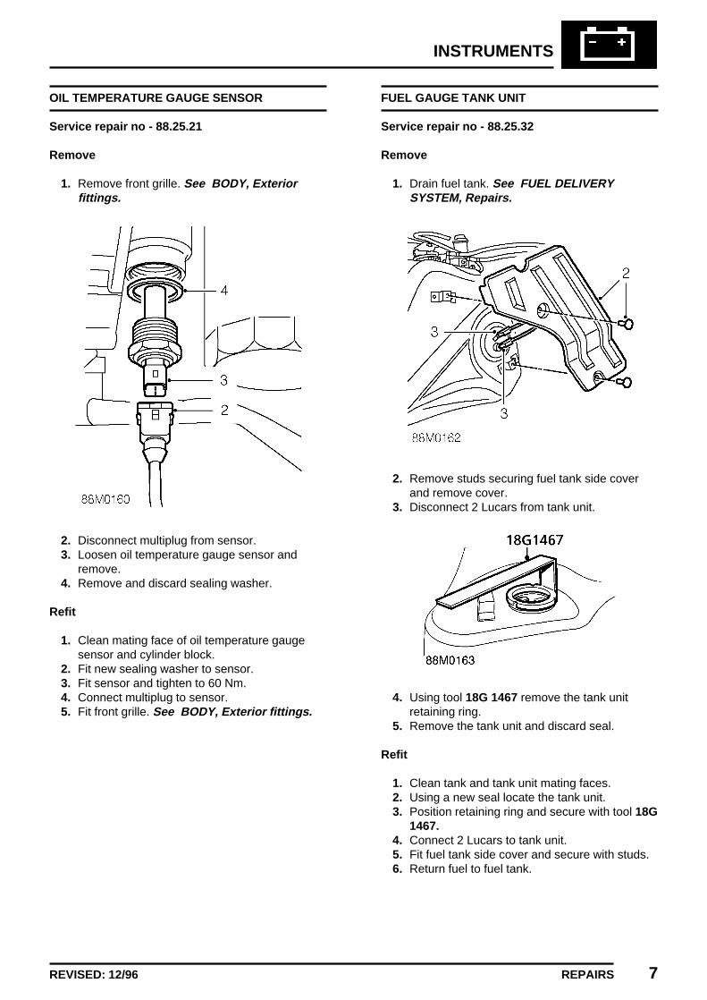
INSTRUMENTS
REPAIRS 7REVISED: 12/96
OIL TEMPERATURE GAUGE SENSOR
Service repair no - 88.25.21
Remove
1. Remove front grille. See BODY, Exteriorfittings.
2. Disconnect multiplug from sensor.3. Loosen oil temperature gauge sensor and
remove.4. Remove and discard sealing washer.
Refit
1. Clean mating face of oil temperature gaugesensor and cylinder block.
2. Fit new sealing washer to sensor.3. Fit sensor and tighten to 60 Nm.4. Connect multiplug to sensor.5. Fit front grille. See BODY, Exterior fittings.
FUEL GAUGE TANK UNIT
Service repair no - 88.25.32
Remove
1. Drain fuel tank. See FUEL DELIVERYSYSTEM, Repairs.
2. Remove studs securing fuel tank side coverand remove cover.
3. Disconnect 2 Lucars from tank unit.
4. Using tool 18G 1467 remove the tank unitretaining ring.
5. Remove the tank unit and discard seal.
Refit
1. Clean tank and tank unit mating faces.2. Using a new seal locate the tank unit.3. Position retaining ring and secure with tool 18G
1467.4. Connect 2 Lucars to tank unit.5. Fit fuel tank side cover and secure with studs.6. Return fuel to fuel tank.

INSTRUMENTS
8 REPAIRS
SPEEDOMETER
Service repair no - 88.30.01
Remove
1. Remove printed circuit See this section.
2. Remove 6 screws securing instrument housingto panel.
3. Remove instrument housing and releasetachometer from housing.
4. Release retainers, remove lens and surroundfrom speedometer housing.
5. Remove 2 screws and remove speedometerfrom housing.
Refit
1. Fit speedometer to housing. Fit and tightenscrews.
2. Fit surround and lens to housing.3. Fit tachometer to housing.4. Fit housing to instrument panel. Fit and tighten
screws.5. Fit printed circuit. See this section.

INSTRUMENTS
REPAIRS 9
SPEEDOMETER DRIVE CABLE
Service repair no - 88.30.06
Remove
1. Disconnect battery earth lead.2. Remove air cleaner. See ENGINE
MANAGEMENT SYSTEM - MEMS, Repairs.3. Remove radio. See ELECTRICAL, Repairs.
4. Disconnect speedometer cable from rear ofinstrument pack.
5. Raise front of vehicle.
WARNING: Support on safety stands.
6. Loosen knurled nut securing speedometercable to gearbox.
7. Release cable grommet from bulkhead.8. Release cable and remove from vehicle.
Refit
1. Fit cable to vehicle.2. Connect cable to gearbox and tighten nut.3. Connect cable to instrument pack and secure
grommet.4. Ensure cable is routed correctly and is not
kinked or twisted.5. Fit radio. See ELECTRICAL, Repairs.6. Fit air cleaner. See ENGINE MANAGEMENT
SYSTEM - MEMS, Repairs.7. Remove stand(s) and lower vehicle.8. Connect battery earth lead.
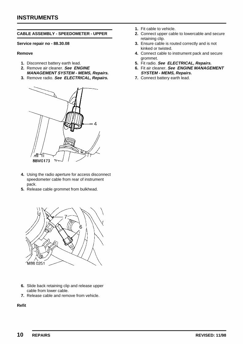
INSTRUMENTS
10 REPAIRS REVISED: 11/98
CABLE ASSEMBLY - SPEEDOMETER - UPPER
Service repair no - 88.30.08
Remove
1. Disconnect battery earth lead.2. Remove air cleaner. See ENGINE
MANAGEMENT SYSTEM - MEMS, Repairs.3. Remove radio. See ELECTRICAL, Repairs.
4. Using the radio aperture for access disconnectspeedometer cable from rear of instrumentpack.
5. Release cable grommet from bulkhead.
6. Slide back retaining clip and release uppercable from lower cable.
7. Release cable and remove from vehicle.
Refit
1. Fit cable to vehicle.2. Connect upper cable to lowercable and secure
retaining clip.3. Ensure cable is routed correctly and is not
kinked or twisted.4. Connect cable to instrument pack and secure
grommet.5. Fit radio. See ELECTRICAL, Repairs.6. Fit air cleaner. See ENGINE MANAGEMENT
SYSTEM - MEMS, Repairs.7. Connect battery earth lead.

INSTRUMENTS
REPAIRS 11ISSUED: 11/98
CABLE ASSEMBLY - SPEEDOMETER - LOWER
Service repair no - 88.30.09
Remove
1. Disconnect battery earth lead.2. Raise front of vehicle.
WARNING: Support on safety stands.
3. Loosen knurled nut securing speedometercable to gearbox.
4. Slide back retaining clip and release lowercable from upper cable.
5. Release cable and remove from vehicle.
Refit
1. Fit cable to vehicle.2. Connect lower cable to upper cable and secure
retaining clip.3. Ensure cable is routed correctly and is not
kinked or twisted.4. Connect cable to gearbox and tighten nut.5. Remove stand(s) and lower vehicle.6. Connect battery earth lead.

INSTRUMENTS
12 REPAIRS ISSUED: 11/98
TACHOMETER
Service repair no - 88.30.21
Remove
1. Remove fascia panel. See BODY, Interiortrim components.
2. Remove screw securing printed circuit totachometer.
3. Remove 2 screws securing tachometerhousing to instrument panel and removehousing.
4. Remove illumination light bulb fromtachometer.
5. Release retainers, remove lens and surroundfrom housing.
6. Remove 2 screws and remove tachometerfrom housing.
Refit
1. Fit tachometer to housing. Fit and tightenscrews.
2. Fit surround and lens to housing.3. Fit housing to instrument panel. Fit and tighten
screws.4. Align printed circuit to tachometer, fit and
tighten screw.5. Fit illumination bulb.6. Fit fascia panel. See BODY, Interior trim
components.