minimizing cr-evaporation from balance of plant …
TRANSCRIPT

1
MINIMIZING CR-EVAPORATION FROM BALANCE OF PLANT COMPONENTS BY UTILIZING COST-EFFECTIVE ALUMINA-
FORMING AUSTENITIC STEELS
Xingbo Liu
Mechanical & Aerospace Engineering DepartmentBenjamin M. Statler College of Engineering & Mineral Resources
West Virginia University
November 18, 2016
DE-FE0027947

Outline
• Project Team Information• Background• Technical Approach• Project Objective• Project Structure• Project Schedule• Project Budget• Risk Management • Technology Readiness Level (TRL)/commercialization goals
DE-FE0027947 2

Project Team Information
PI - Xingbo Liu• Program Management• Cr-release Measurement• On-Cell Testing• TEA• Phase II Preparation
Co-PI - Mike Brady•AFA Development•Oxidation Measurement
Co-PI - Hossein Ghezel-AyaghAlireza Torabi
•Cr-release Measurement•TEA•Phase II Preparation
Industrial Partner – Samuel Kernion• AFA Manufacturing
DE-FE0027947 3

Background - SOFC Stacks
* NETL 2015 SOFC Workshop – FCE Presentation
DE-FE0027947 4

SOFC Long-term Degradation
* NETL 2015 SOFC Workshop – FCE Presentation
DE-FE0027947 5

SOFC Cathode Degradation
• Microstructural changes (loss effective TPB area)o Grain growtho Coarsening of the particleso Surface re-construction
• Chemical reaction with YSZ electrolyte.
• Strontium segregation related issues
• Poisoning of the cathode (e.g. by CO2, chromium species etc.)
2 3( ) ( ) ( )SrO s ZrO s SrZrO s+ →2 3 2 2 7 3( ) 2 ( ) ( )La O s ZrO s La Zr O s+ →
',2 2 2 ( )x
La O LSCF OSr V O SrO s••+ + ↔
2 3( ) ( ) ( )SrO s CO g SrCO s+ →2 2( ) ( ) ( ) ( )SrO s H O g Sr OH s+ →2 3 2 2 2 22 ( ) 3 ( ) 4 ( ) 4 ( ) ( )Cr O s O g H O g CrO OH g+ + →
DE-FE0027947 6

Cr2O3 Related Degradations
Cr poisoning of SOFC Cathode
Reactions with other components
Cr2O3 Sources: Interconnect and BOPCr-distribution @ Cathode/electrolyte Interface
J. Power Sources 162 (2006) 1043–1052
J. Power Sources 152 (2005) 156–167
DE-FE0027947 7

SOFC Interconnect Coatings
0 200 400 600 800 1000 12000.00
0.01
0.02
0.03
0.04
0.05
+ +(1200, 0.02441)
(165, 0.0213)
ASR
(Ohm
.cm
2 )
Time (Hour)
ASR
2
• Various Spinel Coatings (Mn-Co, Mn-Cu, etc.)
• PVD, CVD, Spray, Electroplating, EPD
DE-FE0027947 8

Project Technical Approaches
Developing Cost-Effective Alumina Forming
Austenitic Stainless Steels (AFA), to
replace Austenitic Stainless Steel 316L and
Ni-base Superalloy Inconel 625, for Key
Balance of Plant (BOP) components, to
minimize Cr-Poisoning of SOFC Cathode
Compression Plate in BOP
DE-FE0027947 9
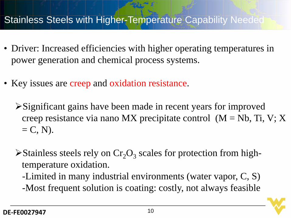
Stainless Steels with Higher-Temperature Capability Needed
• Driver: Increased efficiencies with higher operating temperatures in power generation and chemical process systems.
• Key issues are creep and oxidation resistance.
Significant gains have been made in recent years for improved creep resistance via nano MX precipitate control (M = Nb, Ti, V; X = C, N).
Stainless steels rely on Cr2O3 scales for protection from high-temperature oxidation.-Limited in many industrial environments (water vapor, C, S)-Most frequent solution is coating: costly, not always feasible
DE-FE0027947 10

Development Effort for Low Cost, Creep and Oxidation-Resistant Structural Alloy for Use from ∼600-900°C
• Approach: Al2O3-forming austenitic stainless steels-background and potential advantages
• Current alloy status for microstructure, mechanicalproperties, and oxidation resistance
Solar Turbines 4.6 MW Mercury 50 recuperated low NOx gas turbine engine
Recuperator, Casing
Fossil Power Steam Turbine, Boiler Tubing
Initial target(s)
Tubing in chemical/process industry, etc. also targeted.
DE-FE0027947 11

Cr2O3-Formers Suffer Accelerated Attackin Water-Vapor Environments
Oxidation Data for 347 Stainless Steel Foil (Fe-18Cr-11Ni base)at 650°C in Air and Air + 10% Water Vapor (Pint et al.)
•Susceptibility from Cr-oxide volatility in H2O and enhanced internal oxidation•Particularly important for thin components such as heat exchangers
0.0
0.1
0.2
0.3
0.4
0.5
0.6Sp
ecim
en M
ass G
ain
(mg/
cm2
0 10,000 20,000 30,000 40,000 50,000
Air
Exposure Time (h)
Air + 10% H2O
0.0
0.1
0.2
0.3
0.4
0.5
0.6Sp
ecim
en M
ass G
ain
(mg/
cm2
0 10,000 20,000 30,000 40,000 50,000
Air
Exposure Time (h)
Air + 10% H2O
DE-FE0027947 12

Al2O3 Scales Offer Superior Protection in Many Industrially-Relevant Environments
•Al2O3 has lower growth rate/more thermo. Stability in oxygen than Cr2O3
•Al2O3 highly stable in water vapor•Al2O3 generally (not always) better resistance to carburization and sulfidation
Temperature (oC)
-400
-600
-800
-1000
200 700
NiO FeO
Free
Ene
rgy
(kJ
mol
O2)
NiOCr2O3
α-Al2O3SiO2
1300 1100 900-14
-12
-10
-8
1/Temperature (shown in oC)Para
bolic
Rat
e C
onst
ant (
g2 cm
-4s-1
)
SiO2Cr2O3
Al2O3
Kinetics Thermodynamics
DE-FE0027947 13

Few Available Options for Al2O3-Forming Alloys
•FeCrAl Alloys: Open body-centered cubic structure is weak-Not suitable for most structural uses above ∼500°C
•Ni-Base Alloys/Superalloys: too costly-5 to 10 times greater cost than stainless steels-limited to niche applications with ultrahigh performance needs
•Typically use Al2O3-forming coatings or surface treatments-increases cost-not feasible for many components/applications
DE-FE0027947 14

Challenge of Alumina-forming Austenitic (AFA) Stainless Steel Alloys
• Numerous attempts over the past ∼30 years (e.g. McGurty et al. alloys from the 1970-80’s, also Japanese, European, and Russian efforts)
• Problem: Al additions are a major complication for strengthening strong BCC stabilizer/delta-ferrite formation (weak) interferes with N additions for strengthening
• Want to use as little Al as possible to gain oxidation benefit keep austenitic matrix for high-temperature strength introduce second-phase (intermetallics/carbides) for
precipitate strengthening
DE-FE0027947 15

Composition and Microstructure Considerationsfor AFA Stainless Steels
•Creep Strength- balance Al, Cr, Ni, to maintain single-phase FCC austenitic matrix- Nano NbC and micron/submicron B2-NiAl + Fe2Nb base Laves precipitates
•To form protective alumina: - Ti+V < 0.3 wt.%; Nb > (0.6-1) wt.%; N < 0.02 wt.%
B2/Laves
Laves (Fe2(Mo,Nb)-type) 2mm
B2 (NiAl-type)
NbC
200nm
Typical Fe-(20-30)Ni-(12-15)Cr-(2.5-4)Al-(1-3)Nb-0.1C wt.% Base AFA Alloy Microstructure After Creep
SEM TEM
DE-FE0027947 16

AFA Form Transient Al-Rich Oxide Overlying Inner, Columnar a-Al2O3
TEM of HTUPS 4 After 1000 h at 800°C in Air + 10% Water VaporTime (h)Time (h)
50 nm Alloy
W-sample prep overlayer
Intermixed Al-Cr-Fe-O+Al-Cr-Mn-Fe-O
Al2O3 + Cr2O3 + Porosity
α-Al2O3
• α-Al2O3 the source of the excellent oxidation resistance
• Occasional transient nodules 0.5-5 µm thick, some Nb-oxide also detectedDE-FE0027947 17

NiAl precipitates(dark)
NiAl denuded
10 µm
Al-Cr-Fe-Mn-Nb-O
2.5 µm
• Austenite matrix composition key to forming alumina (Al, C, Cr, Ni)• NiAl precipitates act as Al reservoir to maintain alumina• Nb as MC or Laves important in H2O
Austenite Matrix and NiAl Precipitates Key to Establishing and Maintaining Alumina
SEM-BSE Images of Typical Oxidized Cross-Sectionfor a 4 Al wt.% AFA Alloy (900oC/100h/in air)
Oxide Al2O3 (dark)
Austenite
NiAl precipitates(dark)
DE-FE0027947 18

AFA is a Family of Alloys Three different grades of AFA series (wrought alloys)
– AFA Grade: Fe- (14-15)Cr-(2.5-4)Al-(20-25)Ni-(1-3)Nb wt.% base• ~750-950°C temperature limit for Al2O3 formation • higher temperature ranges need higher Ni and Nb + rare earth
additions• MC and M23C6 strengthening
– Low Nickel AFALN : Fe-14Cr-2.5Al-12Ni-0.6Nb-5Mn-3Cu wt.% base• ~ 650-700°C temperature limit for Al2O3 formation• M23C6 strengthening
– High Creep resistance γ’-Ni3Al strengthened AFA: Fe-(14-19)Cr-(2.5-3.5)Al-(30-35)Ni-3Nb + wt.% base
• ~750-850°C temperature limit for Al2O3 formation
Cast AFA: Cast version of AFA alloysDE-FE0027947 19

Alumina-former
AFA (14Cr-3.5Al) Alloy 120 (25Cr) Cast CF8C (18Cr)
Chromia-former
Advantage Compared to Conventional Chromia Scales
DE-FE0027947 20
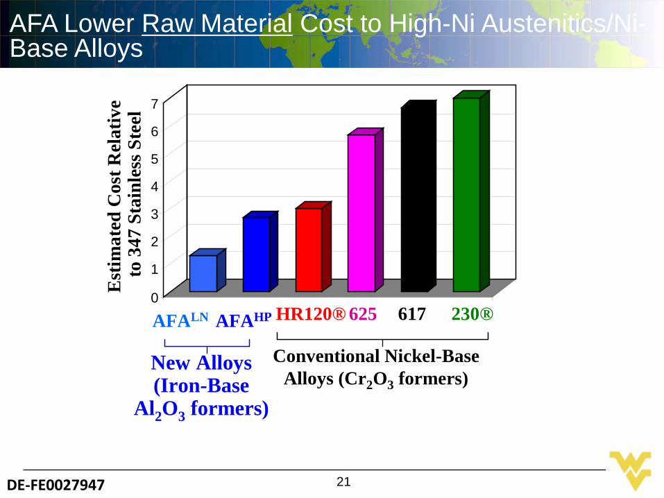
AFA Lower Raw Material Cost to High-Ni Austenitics/Ni-Base Alloys
Est
imat
ed C
ost R
elat
ive
to 3
47 S
tain
less
Ste
el
AFAHP HR120® 625 617 230®
New Alloys(Iron-Base
Al2O3 formers)
Conventional Nickel-BaseAlloys (Cr2O3 formers)
AFALN0
1
2
3
4
5
6
7
1
DE-FE0027947 21

Fusion zone
Original material
AFA Alloys Appear to be Readily Welded (limited data)
Gas Tungsten Arc Weld(used same alloy as a filler material)
• No cracking at fusion/heat-affected zones
(Eutectic or δ)
30µm
DE-FE0027947 22

AFA Highlights
ORNL's AFA licensed to Carpenter Technology Corp.
AFA Steel team: Alan Liby, Alexander DeTrana, Mike Brady, Yukinori Yamamoto; Michael Santella, Joseph Marasco, Bruce Pint, Craig Blue
DE-FE0027947 23

AFA Commercialization: OC4 (14Cr-3.5Al-25Ni-2.5Nb) Products
Carpenter 10,000lb AFA heat (VIM/VAR)
UTRC 6 mil foil subscalebrazed heat exchanger(foil by Elgiloy)
15” wide, 4 mil AFA foil for Solar Turbinesrecuperator (Metalwerks 2000lb heat, Haynes, Somers, Elgiloy)
Elgiloy 8” wide, 300 lb, 3.2 mil coil for Capstone
350 lb wire coilElgiloy to Capstone
Capstone folded 8” wide 3.2 mil Foil
DE-FE0027947 24

Project Objectives – Phase I
Develop and utilize cost-effective alumina forming austenitic steels (AFAs) for balance of plant (BOP) components and pipes in solid oxide fuel cell (SOFC) systems to minimize the Cr-poisoning and improve system stability;
Systematically investigate the influence of the operation condition, i.e., temperature and moisture, on the oxidation and Cr-release from the AFA steels, and their effects on the degradation of SOFC performance
Prepare for Phase II of the project, in which we will manufacture and test the related BOP components in industrial SOFC systems
DE-FE0027947 25

Project Structure
Task 1.0 Project Management and Planning - WVUTask 2.0 Developing and Manufacturing AFAs - ORNL & Carpenter
Subtask 2.1 AFA DevelopmentSubtask 2.2 Microstructure Characterization
Task 3 Studies on Oxidation Kinetics, and Cr Evaporation in simulated SOFC environments – WVU & ORNL
Subtask 3.1 Oxidation Kinetics – ORNLSubtask 3.2 Characterization of the oxide scale - ORNLSubtask 3.3 Cr Evaporation Evaluation – WVU & FCESubtask 3.4 Contributions of partial pressure of different Cr species - WVU
Task 4.0 Cr-poisoning of SOFC cathode in associate with BOP materials - WVUSubtask 4.1 Assembly of SOFCs with BOP AlloysSubtask 4.2 Electrochemical InvestigationsSubtask 4.3 Post-Mortem Analyses
Task 5 Preparation for Phase II – WVU, ORNL, Carpenter and FCE
DE-FE0027947 26

Project Timeline
I.D. Task Year 1 Year 2Q1 Q2 Q3 Q4 Q5 Q6
1.0 Project Management2.0 Developing & Manufacturing AFAs2.1 AFA Development2.2 Microstructure
Characterizations3.0 Oxidation and Cr Evaporation in Simulated SOFC Environments3.1 Oxidation Kinetics3.2 Scale characterization3.3 Cr Evaporation Evaluation3.4 Contributions of partial
pressure of different Cr species
4.0 Investigation on Cr-poisoning of SOFC in associate with BOP Alloys4.1 Assembly of SOFCs with
BOP Alloys4.2 Electrochemical
Investigations4.3 Post-Mortem Analyses5.0 Phase II preparation
Note: = Decision Points
DE-FE0027947 27

Project Budget
Period 1 (Year 1) Period 2 (6 Months) TotalDOEFunds
Cost Share
DOE Funds
Cost Share
West Virginia University $ 231,577 $ 47,478 $ 108,422 $ 34,139 $ 421,616 Oak Ridge National Lab $ 80,000 $ - $ 50,000 $ - $ 130,000 Fuel Cell Energy $ 30,000 $ 7,500 $ - $ - $ 37,500 Carpenter Technology 0 $ 40,000 $ - $ - $ 40,000 Total $ 341,577 $ 94,978 $ 158,422 $ 34,139 $629,116.00
DE-FE0027947 28

Risk Management
Risk 1Achieving long-term protective alumina scale formation at the upper end of the SOFC BOP component use temperature range, ∼900-950°C.
Risk 1 Mitigation
We have recently identified an AFA composition that can form alumina at 1100°C. This is achieved by higher Al, Cr and Ni levels, which will need to be evaluated for impacts on Cr release rate
Risk 2
The Cr content in the alumina-base surface oxide layer formed by AFA resulting in unacceptably high Cr release rates at both the high-temperature and low-temperature ends of the SOFC BOP component use temperature range.
Risk 2 Mitigation
Transient oxidation and the amount of Cr incorporated into the alumina-base surface layer will be critical. This can be controlled to an extent by minor alloying additions, particularly Hf, Y, Zr, as well as the balance of Al Cr, Ni, and Fe levels. For both issues we will use computational thermodynamic calculations to quickly screen proposed composition changes for feasibility (e.g. maintaining austenitic matrix, second phases formed).
DE-FE0027947 29

TRL/Commercialization Goals
TRL (Phase I beginning) – 3
TRL (End of Phase I) – 4
Commercialization Goals –Developing and Employing AFA in Industrial SOFC Systems
AFA Manufacture – Carpenter TechnologiesSOFC Developer – Fuel Cell Energy
Preliminary results on Cr-evaporation rates of AFA and related alloys (ORNL data)
DE-FE0027947 30

Acknowledgement
• NETL-SOFC Team: Shailesh Vora, Heather Guedenfeld, Joel Stoffa, etc.
• Co-PIs: Mike Brady (Oak Ridge National Lab), Hussein Ghezel-Ayagh, Ali Torabi (FCE)
• Industrial Partner: Samuel Kernion (Carpenter)
DE-FE0027947 31